design specification for a thrust-vectoring, actuated … 3 lateral/directional feedback control law...
TRANSCRIPT

NASA Technical Memorandum 110217
J
f
Design Specification for a Thrust-Vectoring,Actuated-Nose-Strake Flight Control Lawfor the High-Alpha Research Vehicle
HARV Control Law Design Team
Langley Research Center, Hampton, Virginia
Mayl_6
National Aeronautics and
Space Administration
Langley Research Center
Hampton, Virginia 23681-0001
https://ntrs.nasa.gov/search.jsp?R=19960044512 2018-06-26T16:59:51+00:00Z


TABLE OF CONTENTS
Acronyms ........................................................................................... ivChapter 1 General .................................................................................. 1
1.1 Introduction .......................................................................... 1
1.2 NASA- IA Implementation ......................................................... 21.3 Reference ............................................................................. 2
Chapter 2 Longitudinal Control Law ............................................................ 32.1 Functional Description .............................................................. 32.2 Implementation ...................................................................... 32.3 Input/Output Lists ................................................................... 32.4 Block Diagram ....................................................................... 6
2.4.1 Flow Chart Notation ..................................................... 6
2.4.2 Calculated Inputs Required ............................................. 142.4.3 Approach to Calculation of Dynamic Filters .......................... 142.4.4 Technique for Engage ................................................... 14
2.5 References ............................................................................ 15
Chapter 3 Lateral/Directional Feedback Control Law .......................................... 173.1 Functional Description .............................................................. 173.2 Implementation ................................... . .................................. 183.3 Specification Description ........................................................... 18
3.3.1 Lateral Stick Command Path ........................................... 20
3.43.5
3.3.2
3.3.1.13.3.1.23.3.1.33.3.1.43.3.1.53.3.1.63.3.1.73.3.1.8
Pedal3.3.2.13.3.2.23.3.2.3
Lateral Stick Deadband and Shaping Function ............ 20Stick Coordination ........................................... 20
Stick Dynamic Limiter and Roll Trim ...................... 20Yaw Rate Limiter ............................................. 20Roll Override .................................................. 25
Nz Filter and Adjustment .................................... 25Stick Command Gain ........................................ 25Lateral Stick Cross-Gain .................................... 26Command Path .................................................... 28
Pedal Deadband, Shaping Function, and Yaw Trim ..... 28Pedal Command Gain ........................................ 28Rudder Pedal Cross-Gain ................................... 31
3.3.3 Feedback Signal Path .................................................... 313.3.3.1 Filtering, Transformation, and Compensation ofSensed Roll and Yaw Rates ........................................... 31
3.3.3.2 Ny Filtering and Offset Correction ......................... 323.3.3.3 Ny Interference Correction .................................. 353.3.3.4 Betadot Feedback Signal .................................... 353.3.3.5 Roll and Yaw Feedback Gain Tables ...................... 36
3.3.3.6 Strake Deployment Compensation ......................... 363.3.4 Command Summation Block ........................................... 37
3.3.4.1 Lateral Command Summation and Filtering ............... 373.3.4.2 Directional Command Summation and Filtering .......... 37
3.3.5 Pseudo Controls Interface and Command Limiting .................. 383.3.5.1 Pseudo-Controls Interface ................................... 383.3.5.2 Control Effector Command Limits ......................... 43
3.3.5.3 Aileron Trailing-Edge-Down Deflection Limit ............. 443.3.5.4 Strake Linearizing Function .................................. 44
3.3.6 Mode Switching Logic .................................................. 44Control Law Inputs and Outputs .................................................. 49
References ............................................................................ 50
Chapter 4 Lateral/Directional Pseudo Controls ................................................ 514.1 General ............................................................................... 51
4.1.1 Modules ............. . ..................................................... 554.1.2 Multirate Clock .......................................................... 56
4.2 Module Descriptions ................................................................ 564.2.1 AC_PSEUDO_CONTROLS (USR39FJL) .......................... 57
4.2.1.1 Update Multirate Clock ...................................... 574.2.1.2 Differential Stabilator Authority ............................ 574.2.1.3 Subroutine Calls ............................................. 58
4.2.1.4 Thrust-Vector Scaling ....................................... 584.2.1.5 Accelerometer Correction ................................... 58
4.2.2 DX_FYAW_FUNCTION (USR33FJL) ............................. 584.2.2.1 FYAW Tables ................................................ 594.2.2.2 FYAW Calculation ........................................... 60
4.2.3 DX_FROLL_FUNCTION (USR33FJL) ............................ 604.2.3.1 FROLL Tables ............................................... 614.2.3.2 FROLL Calculation .......................................... 62
4.2.4 DX_DISTRIBUTOR_GAINS (USR36FJL) ........................ 624.2.4.1 Roll Distributor Gains ....................................... 624.2.4.2 Yaw Distributor Gains ...................................... 63
4.2.5 DX_STRAKE_ENGAGE(USR59FJL) .............................. 64
4.2.5.1 Forebody Strake Schedules (ANSER) .................... 644.2.5.2 Strake Deploy/Engage Logic (ANSER) ................... 654.2.5.3 Available Strake Yaw Moment (ANSER) ................. 65
4.2.6 DX_YAWTV_ENGAGE (USR52FJL ............................... 66
4.2.6.1 Yaw-Moment Capability of Aerodynamic Controls ..... 664.2.6.2 Yaw-Moment Capability of Thrust-Vectoring Controls. 664.2.6.3 Limited Ratio of Aerodynamic and Yaw Thrust-
Vectoring Moments .................................................... 674.2.6.4 Yaw Thrust-Vector Automatic Engagement Schedule... 674.2.6.5 Yaw-Thrust Vector Engagement Logic .................... 684.2.6.6 Available Yaw Moment ..................................... 68
4.2.7 DX_ROLLTV_ENGAGE (USR51FJL) ............................. 694.2.7.1 Roll-Moment Capability of Aerodynamic Controls ...... 694.2.7.2 Roll-Moment Capability of Thrust-Vectoring Controls. 694.2.7.3 Limited Ratio of Aerodynamic and Roll Thrust-Vectoring Moment ...................................................... 704.2.7.4 Roll Thrust-Vector Automatic Engagement Schedule ... 714.2.7.5 Roll Thrust--Vector Engagement Logic .................... 714.2.7.6 Available Roll Moment ...................................... 72
4.2.8 DX_INTERCONNECT (USR35FJL) ................................ 724.2.8.1 Axis Transformation ......................................... 724.2.8.24.2.8.34.2.8.44.2.8.54.2.8.64.2.8.74.2.8.8
4.2.9
Inertial Coupling ............................................. 72Moments ...................................................... 73Available Moment Limits ................................... 73
Available Accelerations ...................................... 74VYAW Pseudo Control ..................................... 74
Nozzle Compensation ....................................... 74VROLL Pseudo Control .................................... 75
AC_DISTRIBUTOR (USR38FJL) ................................... 754.2.9.1 Yaw Thrust-Vector Pseudo Control ....................... 754.2.9.2 Roll Thrust-Vector Pseudo Control ........................ 754.2.9.3 Vane Relief ................................................... 75
4.2.9.4 Yaw Thrust-Vectoring Pseudo Control Relief ............ 76
ii
4.2.9.5 Yaw Pseudo Control Relief .................................. 76
4.2.9.6 Roll Thrust-Vectoring Pseudo Control Relief ............. 764.2.9.7 Roll Pseudo Control Relief .................................. 774.2.9.8 Distribution of Pseudo Controls ............................. 774.2.9.9 Accelerometer Correction .................................... 79
4.2.10 DX_YAW VANE RELIEF(USR54FJL) ............................ 794.2.10.1 VYAW Required ............................................ 794.2.10.2 Positive Limit ................................................ 80
4.2.10.3 Negative Limit ............................................... 804.2.10.4 Yaw-Relief Authority ....................................... 80
4.2.10.5 Yaw-Relief Dynamics - Nonlinear Low-Pass Filter .... 814.2.11 DX_ROLL VANE RELIEF (USR53FJL) .......................... 82
4.2.11.1 VROLL Required ........................................... 824.2.11.2 VROLL Authority ........................................... 824.2.11.3 Roll-Relief Dynamics - Nonlinear Low-Pass Filter .... 83
4.2.12 DX_STRAKE CONTROLS (USR58FJL) .......................... 844.2.12.1 Differential Strake Command (ANSER) ................. 84
4.2.12.2 Strake Command Mixing (ANSER) ...................... 844.2.12.3 Individual Strake Commands (ANSER) ................. 844.2.12.4 Accelerometer Correction (ANSER) ...................... 85
4.2.13 Common Storage ....................................................... 854.3 Horizontal Block Diagram .......................................................... 87
4.3.1 Input - Output Lists ...................................................... 884.4 References ............................................................................ 90
Chapter 5 Interface ................................................................................. 995.1 General ............................................................................... 99
5.2 Input and Instrumentation Lists .................................................... 995.3 Calculated Inputs .................................................................... 1035.4 Remarks .............................................................................. 105
.°.
Ul
Acronyms
AC
ANSER
AOA
CRAFT
DMS
FFCG
HARV
HBD
I/O
INS
LaRC
NASA-0
NASA-1A
OBES
Phase II
Phase III
RAM
RFCS
S-mode
STV-mode
TED
TEU
TV
TV-mode
WOW
701E
aircraft
Actuated Nose Strakes for Enhanced Rolling
angle of attack
Control power, robustness, agility, and flying qualities trade-off
Differential Maneuvering Simulator
feed-forward command generator
High Alpha Research Vehicle
horizontal block diagram
input/output
inertial navigation system
Langley Research Center
baseline thrust-vectoring control law
Advanced thrust-vectoring control law flown during Phase II
On-Board Excitation System
Flight phase (Jan. - Jun. 1994) for evaluating HARV Thrust-Vectoring System
Flight phase for evaluating HARV ANSER System
random access memory
Research Flight Control System
thrust-vectoring control-law mode
nose-strake plus thrust-vectoring control-law mode
trailing-edge down
trailing-edge up
thrust vectoring
thrust-vectoring control-law mode
weight-on-wheels
Pace 701E research flight computer
iv

Chapter IGeneral
I.I Introduction
The main objective of this specification is to document the HARV ANSER Control Laws insufficient detail for use as a source from which an engineer/programmer can produce computer
source code to implement the control laws in flight software. The secondary objective is toprovide information on the control laws to assist a controls engineer in understanding thecontrol laws, debugging source code, writing test plans, and analyzing test data.
The ANSER Control Laws were implemented in the Research Flight Control System(RFCS) and flown on the F/A-18 HARV (High Alpha Research Vehicle) after it was modifiedto install the Actuated Nose Strakes for Enhanced Rolling (ANSER). To meet the operational
requirements with the modified HARV, the Control Laws must provide three modes ofoperation: 1) the TV (thrust-vectoring) mode for use with thrust vectoring when the nosestrakes are not being used in a closed-loop manner; 2) the S (strake) mode for use when thestrakes are in use, but yaw thrust vectoring is not, and 3) the STV (strake/thrust vectoring)mode for use when both strakes and yaw thrust vectoring are in use. Pitch thrust vectoring isused in all three modes. The TV mode is used during "Program-a-Strake" operation.
"Program-a-Strake" operation involves deploying the nose strakes to pre-determined positionsin an open-loop manner to obtain strake aerodynamic data while the pilot controls the aircraftusing the ANSER Control Laws.
The nose strakes are primarily a directional control effector and have little effect in the pitch
axis. Thus, the ANSER Longitudinal Control Law is based on the NASA-1A LongitudinalControl Law (ref. 1.1), but some modifications have been incorporated as a result of NASA-
l A flight test results. The ANSER Lateral/Directional Control Law design effort used theNASA-1A Lateral/Directional Control Law design as a starting point. This design wasmodified as discussed in Chapters 3 and 4 to accommodate the nose strakes and provide the
three modes of operation. Even though the ANSER Longitudinal Control Law design wasthoroughly evaluated during the design of the NASA-1A Control Laws, the ANSERLongitudinal and Lateral/Directional Control Laws were extensively evaluated as a integratedall-axis control law in piloted simulation using the Langley Differential Maneuvering Simulator(DMS) during the ANSER design phase. Langley and Dryden research test pilots were used inthe formal DMS piloted evaluation, and Langley engineering pilots have also flown the controllaws in the DMS. Throughout the design and evaluation process, control law performance wascontinually compared with the HARV control design guidelines.
During the design and linear analysis phase extensive use was made of MATRIXx ®,
Version 7.24, and MATRIXx ® with SystemBuild TM Workstation Versions 2.04 and 2.4.
From the SystemBuild TM implementation the control laws were encoded in FORTRAN using
the MATRIXx ® FORTRAN AutoCode TM Generator Versions 2.21 and 2.23. This FORTRAN
AutoCode TM was then implemented in batch and piloted HARV simulations for control lawevaluation. The ACSL batch simulation hosted on the VAX 3200's operating underVAX/VMS V5.5 and on the Unix-basedSun SPARCstation 10 and the piloted simulation in the
DMS were based on Dryden's F-18 HARV batch simulation, Releases 1 through 13.
Detailed specifications for the ANSER control laws are presented in subsequent chapters ofthis document: Chapter 2 describes the Longitudinal Control Law, Chapter 3 describes theLateral/Directional Feedback Control Law, and Chapter 4 describes Pseudo Controls portion of
theLateral/DirectionalControlLaw. Thesechapterscontainblockdiagrams,input/outputlists,andMATRIXx ® SystemBuildTM diagrams. Chapter 3 also contains a discussion of the design
technique used for the Lateral/Directional Feedback Control Law and a functional descriptionof the control law. A similar detailed discussion for the Longitudinal Control Law is contained
in reference 1.2. Chapter 5 defines the interface between the ANSER Control Law and otherflight software in the form of input and output lists, including outputs for diagnostic purposesonly. In these chapters some references are made to the NASA-0 Control Law. NASA-0refers to the Research Flight Control System developed by McDonnell Douglas and flown onthe HARV during Phase II flight tests.
The basic up-and-away control law defined by this specification is the same for
implementation in simulation and in flight code. However, implementation in real-time flightcode requires some functions, such as ARM and ENGAGE, that are not relevant to the controllaw's basic performance and are not included in the specification. Likewise, some featuresused in simulation, such as a facility for linear model computation, are also not included. In afew cases, elements that are applicable only to simulation or to flight code are so noted in thetext.
1.2 NASA-1A Implementation
An earlier version of the ANSER Control Laws, designated NASA- 1A Control Laws, was
flight tested on the HARV during the Phase II flights. During Phase II the aircraft was notequipped with nose strakes, so the control laws operated only in the TV mode. The parts ofthe Lateral/Directional Control Law that are used only in the S mode or the STV mode are
clearly marked in Chapters 3 and 4. These parts were not implemented in the NASA-1A flightcode.
Results of the NASA-1A flight tests led to some modifications to the original ANSERControl Law design to improve performance. Those modifications are included in the controllaws defined by this specification.
1.2
Reference
Ostroff, Aaron J.; Hoffier, Keith D.;and Proffitt, Melissa S.: High-Alpha ResearchVehicle (HARV) Longitudinal Controller." Design, Analyses and Simulation Results,NASA TP 3446, July 1994.
Ostroff, Aaron J.; and Proffitt, Melissa S.: Longitudinal-Control Design Approach for
High-Angle-of-Attack Aircraft. NASA TP 3302, Feb. 1993.
Chapter 2
Longitudinal ControlVersion 151
Law
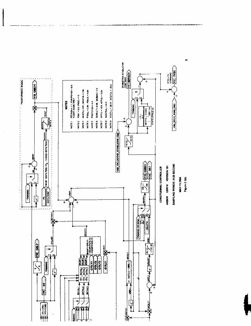
2.1 Functional Description
The ANSER Longitudinal Controller is composed of a feed-forward command generator(FFCG) and a feedback controller that was designed using a Variable Gain Output Feedback
technique (refs. 2.1 to 2.4). The feedback controller is a direct digital design based upon asample rate of 80 Hz and is implemented in incremental form. Feedback variables are pitchrate, angle of attack, and normal acceleration, and the controls are horizontal stabilator andpitch thrust vectoring. Scaling parameters for the variable feedback gains are a function ofangle of attack, impact pressure, static pressure, and some combinations. Flaps (leading andtrailing edge) are scheduled as in the basic F/A-18 Controller. The objective of the FFCG is torelate pilot commands into equivalent commands to the feedback controller. Both the FFCGand the feedback controller are combined and implemented for multi-rate use. Flap logic,
feedback gains, angle-of-attack (AOA) selection logic, sine(AOA), and cosine(AOA) areimplemented at a slower rate of 40 Hz. For a more complete functional description of theLongitudinal Controller, see references 2.3 and 2.4.
2.2 Implementation
The Longitudinal Control Law was implemented in two subroutines, USR 18V 151 and
USR 19V 151, using the MATRIXx ® FORTRAN AutoCode TM generator. The definition andunits of all inputs and outputs for these subroutines are described in Section 2.3 in Tables 2.1through 2.6 for the INPUTS, OUTPUTS, and STATES (trimming coefficients). Symbols
shown in the second column of these tables are those used in the MATRIXx ® FORTRAN
AutoCode TM. The horizontal flow charts in Section 2.4 show the complete longitudinalcontroller. Variable names in the flow charts match the variable names in the FORTRAN
AutoCode TM implementation. In case of discrepancies between documentation sources such as
number of significant figures in constants, AutoCode TM is the defining source. AutoCode TM
and the horizontal block diagrams should agree in these cases. Figure 2.1 (a) (forUSR 18V 151) has three colums of stored gains labled "DEFAULT", "GAINSET 1, and"GAINSET2". These are for DIAL-A-GAIN use where each set of gains will be used
separately for evaluation during specified flight maneuvers, with the DEFAULT set usedinitially. DIAL-A-GAIN refers to the flight software logic by which the pilot can select anyone of three sets of gains for the Longitudinal Control Law.
2.3 Input/Output Lists
NO
1
2
3
4
5
6
Table 2. - Subroutine USRI8V151 - INPUTS
AUTO CODE DEFINITIONSYMBOL
AOAP
AOAINS
QCFILTER2
PS
RI Pressure ratio - (QCFILTER2/PS)
TRMMING Trim flag (real): 0.0 = Operate1.0 = Trim
Angle-of-attack PROBE (deg)
Angle-of-attack INS (deg)
10 rad/sec filtered imapact pressure (lb/ft 2)Static Pressure (lb/ft z)
3

Table 2.2 - Subroutine USR18V151 - OUTPUTS
AUTO CODE DEFINITION
SYMBOL
TEFSC 1
NO
1
2
34
5
6
7
8
910
11
12
1314
15
16
17
LEFSC1
AOA
FGI
GTILY1GTILY2
GTILY3
GTILU 1
GTILZ 1
RHON 1
RHON2RHON3
RHON4
RHON5
RHON6
Collective trailing-edge-flap command (deg
Collective leading-edge-flap command (deg)Angle-of-attack faded between probe and INS (deg)Fader gain input for AOA (used to initialize fader gainstate)
COSALFSINALF Sine of AOA
Table 2.3 - Subroutine USR18V151 - STATES (1)
NO FORCING FUNCTION
Feedback gain (proportional) for angle-of-attack
Feedback gain (proportional) for pitch rate
Feedback gain (proportional) for load factor
Feedback gain for filterFeedback gain for integrator
1st variable gain-schedule parameter
2nd variable gain-schedule parameter
3rd variable gain-schedule parameter4th variable gain-schedule parameter
5th variable gain-schedule parameter
6th variable gain-schedule parameterCosine of AOA
X(2) Y(4) - FGI
X(3) Y(3)- AOA
X(4) Y(3)- AOA
EQUATION- TRIMX(2) - 0.8888889"Y(4)
X(3) = 0.9844237"Y(3)
X(4) = 0.9689441"Y(3)
(1) There are a total of 4 states which are updated within AutoCode TM. State coefficients 2 to 4
are only used when the controller is trimming and are calculated for a sampling period of 0.025second. If desired, these states can still be updated externally, X(I)=XD(I).
Table 2.4 - Subroutine USR19VlS1 - INPUTS
NO
1
2
3
4
5
6
7
8
9
10
1112
AUTO CODE DEFINITIONSYMBOL
PSTICK Pitch stick (inch)
PTRIM Pitch trim (inch)
OBES_LONST
AOA
QNZ
QCFILTER1
QCFILTER2PS
GTILY 1
GTILY2GTILY3
OBES (1) longitudinal stick
Angle-of-attack faded between probe and INS (deg)
Pitch rate (deg/sec)
Normal acceleration (g) - positve along negative z-axis
2.5 rad/sec filtered impact pressure (lb/ft 2)
10 rad/sec filtered imapact pressure (lb/fl 2)Static Pressure (lb/ft z)
Feedback gain (proportional) for angle-of-attack
Feedback gain (proportional) for pitch rateFeedback _ain (proportional) for load factor
4

Table2.4- Concluded
AUTOCODE DEFINfI'IONSYMBOLGTILU 1 Feedbackgainfor filter
NO
13141516171819202122
23
24
GTILZ1VT
COSALFSINALFCOSTHESINTHECOSPHIDELSTM
TRMMING
Feedbackgainfor integratorTrueairspeed(ft/sec)Cosineof angle-of-attackSineof angle-of-attackCosineof thepitchangleSineof thepitchangleCosineof theroll angleStabilator,andpitchjet commandedpositionfor trim (deg)Trim flag (real): 0.0= Operate
1.0= TrimOBE_COLLECTIVE OBEScollectivestabilatorcommand(deg)
_STABI.LATORCMD
OBE_PITCH OBESpitch thrustvectoringcommand(deg)_VANE_CMD
(1) OBES - On-Board Excitation System - Provides computer-generated commands to control
surfaces and control system
Table 2.5 - Subroutine USR19V151 - OUTPUTS
AUTO CODE DEFINITIONSYMBOL
SBPAC 1 Collective stabilator command (deg)
NO
12
3
4
5
6
7
8
9
1011
12
13
TVSC
PSGTOTYCMD Command to the feedback control
AOATR
DY
DELY
QCOMP
QCOMP1VBRK1
UK1
UME11
KCGT
Pitch thrust vectoring command (deg)Total stick command (inch)
Estimated angle-of-attack trim
Error in regulated variableError in regulated variable limited to max of 5.0. Used by
pilot to trim stick position.
Compensated pitch-rate (deg/sec)Gravity compensation in pitch-rate signalRate command for stabilator
Control variable for stabilator command (deg)
Feedforward control variable (deg/sec)
Feedforward gain

Table 2.6 - SubroutineUSR19V151 - STATES (1)
NO
X(8)FORCING FUNCTION
Y(12) - QCOMP1E(]UATION - TRIM
X(8) = .8421053"Y(12)
X(9) U(5)- Q X(9) = 1.3459"U(5)
x(10) u(5) - Q x(10) = 1.3459"u(5)x(11) u(6) - NZ X(11) = 18.656716"U(6)
X(12) U(6)- NZ X(12) = 18.656716"U(6)
X(13) U(6)- NZ X(13) = .4326"U(6)
X(14) U(6) - NZ X(14) = .4326"U(6)
X(15) U(6) - NZ X(15) = .4326"U(6)
X(16) U(9)- PS X(16) = .4326"U(9)
X(17) Y(1) - SBPAC 1 X(17) = .993785" Y(1 )
(1) There are a total of 17 states which are updated within AutoCode TM. State coefficients 8 to
17 are only used when the controller is trimming and are calculated for a sampling period of0.0125 second. During trim states 1 to 7 are updated by setting X(I)=XD(I), and after trim allstates are updated using this equation.
2.4 Block Diagram
A complete block diagram of the Longitudinal Control Law is shown in figure 2.1. Thefollowing subsection describes special flow chart notation, special inputs that are needed, andcertain calculations that may not be obvious from the flow charts.
2.4.1 Flow Chart Notation
The diagram above represents a summer where y - ul + u2..
The diagram above represents a multiplier where y = u 1 * u2.
The diagram above represents a limiter with lower limit LL and upper limit UL as
y=u ifLL<u<ULy = LLifu <LLy = UL ifu > UL.
6

,,-,,.
T
ii |J_
i ........
,


IF-
II

IO
,!|
°
" t"ii_i_. ,,
..... iii
I, ,:i .....
_o
4
.| L_
Q
÷ ,
!E
0
0
ii °


E


uABS
The diagram above represents an absolute value condition where y = Iu I.
uThe diagram above represents a logical IF, THEN, ELSE statement.If FLAG is TRUE y = ul, ELSE y = u2.
u g
The diagram above represents a dynamic element for a one sample period time delay as
Xk+l = Uk
Yk = xk
where the subscript k represents the sample number.
ul s+l
"- 1.9875776 .125.09876163 .00621118
STATE-SPACE (z)
Yy
The diagram above represents a dynamic element with one state. The continuous transferfunction is shown on top and the discrete state-space representation is shown on the bottom.The discrete version is to be used in the code as shown in the example
xk+l = 0.9875776 xk + 0.125 uk
Yk = 0.09876163 xk + 0.00621118 Uk
where the subscript k represents the sample number. The approach used to calculate dynamicfilters is shown in a later section.
13
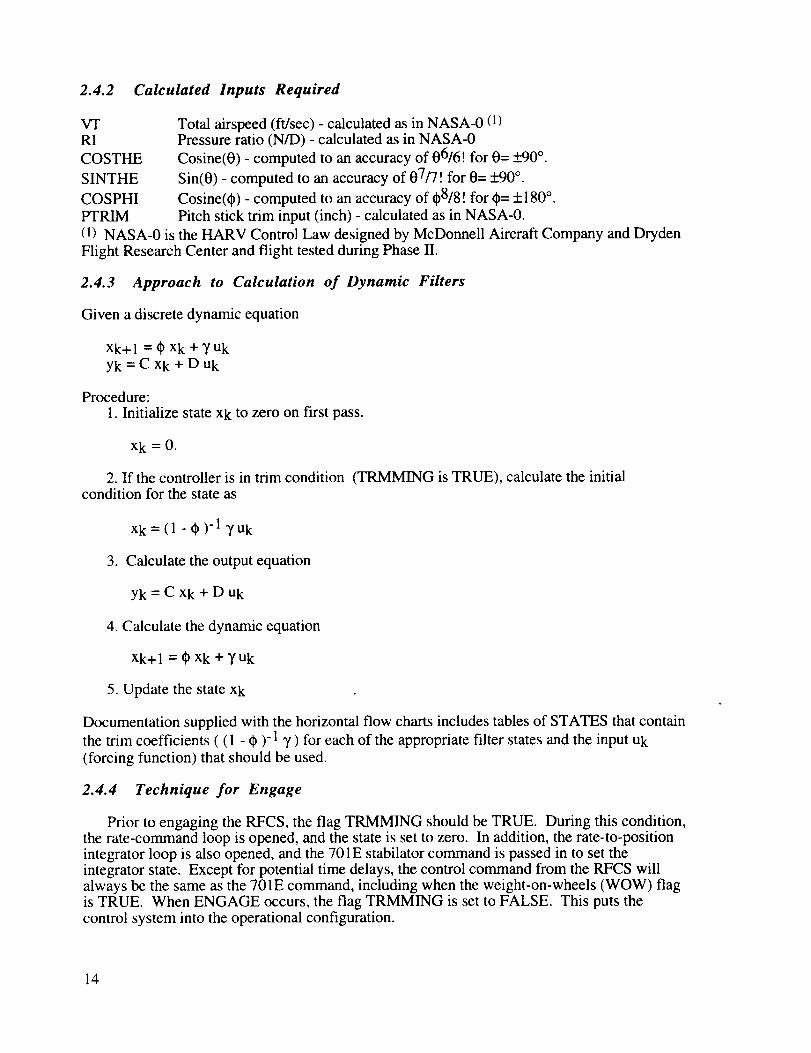
2.4.2 Calculated Inputs Required
VTRI
COSTHE
SINTHE
COSPHI
PTRIM
Total airspeed (ft/sec) - calculated as in NASA-0 (1)Pressure ratio (N/D) - calculated as in NASA-0
Cosine(0) - computed to an accuracy of 06/6! for 0= _+90°.
Sin(0) - computed to an accuracy of 07/7! for 0= _+90°.
Cosine(0) - computed to an accuracy of 08/8 ! for 0= + 180 °.
Pitch stick trim input (inch) - calculated as in NASA-0.
(1) NASA-0 is the HARV Control Law designed by McDonnell Aircraft Company and Dryden
Flight Research Center and flight tested during Phase II.
2.4.3 Approach to Calculation of Dynamic Filters
Given a discrete dynamic equation
Xk+ 1 = 0 xk + y Uk
Yk = C Xk + D Uk
Procedure:
1. Initialize state xk to zero on first pass.
Xk=0.
2. If the controller is in trim condition (TRMMING is TRUE), calculate the initialcondition for the state as
Xk= (1 - 0)-1 yuk
3. Calculate the output equation
Yk = C Xk + D uk
4. Calculate the dynamic equation
xk+ I = 0 xk + 7 uk
5. Update the state xk
Documentation supplied with the horizontal flow charts includes tables of STATES that contain
the trim coefficients ( (1 - 0 )- 1 7 ) for each of the appropriate filter states and the input Uk
(forcing function) that should be used.
2.4.4 Technique for Engage
Prior to engaging the RFCS, the flag TRMMING should be TRUE. During this condition,the rate-command loop is opened, and the state is set to zero. In addition, the rate-to-positionintegrator loop is also opened, and the 701E stabilator command is passed in to set theintegrator state. Except for potential time delays, the control command from the RFCS willalways be the same as the 701E command, including when the weight-on-wheels (WOW) flagis TRUE. When ENGAGE occurs, the flag TRMMING is set to FALSE. This puts the
control system into the operational configuration.
14

2.2
2.3
2.4
References
Halyo, Nesim; Moerder, D.D.; Broussard, J.R.; and Taylor, D.B.: A Variable-GainOutput Feedback Control Design Methodology. NASA CR-4226, March 1989.
Ostroff, A. J. : High-Alpha Application of Variable-Gain Output Feedback Control.Journal of Guidance, Control, and Dynamics, Pages 491-497, Volume 15, Number 2,March-April 1992.
Ostroff, Aaron J.; and Proffitt, Melissa S.: Longitudinal-Control Design Approach for
High-Angle-of-Attack Aircraft, NASA TP-3302, February 1993.
Ostroff, Aaron J.; Hoffler, Keith D. ;and Proffitt, Melissa S.: High-Alpha ResearchVehicle (HARV) Longitudinal Controller: Design, Analyses and Simulation Results,NASA TP 3446, July 1994.
15
Intentionalblankpage
16

CHAPTER 3
Lateral/Directional Feedback
Version 151
Control Law
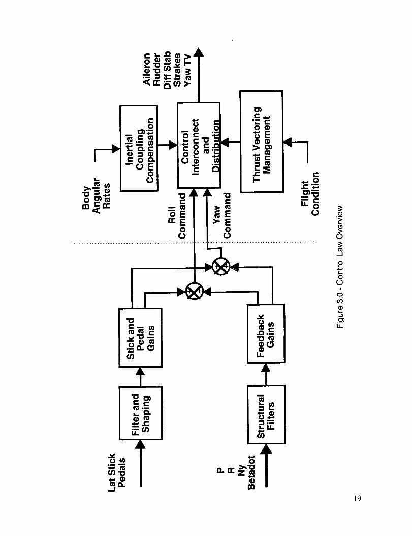
3.1 Functional Description
The ANSER Lateral/Directional Control Law is an innovative control augmentation system
for the HARV flight test vehicle. This control law was developed utilizing the Pseudo Controlsand CRAFT design methods, which are currently being researched at NASA LaRC (refs.3-1,3-2 ). Pseudo Controls is a nonlinear control blending strategy which translates roll and yawcommands into an optimum combination of control surface and thrust vectoring controldeflections which provide maximum stability-axis roll and yaw moments. The CRAFT controldesign method is used to compute measurement feedback gains. It is a combination of Direct
Eigenspace Assignment (ref. 3-3) and a graphical approach for optimizing robustness, agility,and flying qualities requirements, while simultaneously respecting the available aircraft control
power. The combination of CRAFT and Pseudo Controls facilitated production of alateral/directional control law which provides good flying qualities, system robustness, andmaximum agility within the constraints of the available control power and flying qualities
requirements.
Figure 3.0 shows a functional diagram of the ANSER Lateral/Directional Control Law.Pilot inputs to the control law are stability-axis roll rate through lateral stick deflections and"conventional" yaw command through pedal deflections. Pilot inputs are modified and shapedbefore being multiplied by input gains and summed with feedback signals which have been
passed through structural filters and multiplied by CRAFT feedback gains. The feedbackmeasurements are body-axis roll rate, body-axis yaw rate, lateral acceleration, and sideslip rate.The sum of pilot inputs and feedback measurements produce stability-axis roll and yawacceleration commands, or Pseudo Control commands, vlat and vdir. These lateral anddirectional commands are distributed by Pseudo Controls into the optimum blend of controldeflections. The controls being used are aileron, rudder, differential stabilator, yaw thrustvectoring, and nose strakes. The ANSER control law does not use differential leading andtrailing edge flaps. Roll thrust vectoring is not used, but a capability exists to use this control ifdesired.
Within the Pseudo Controls portion of the control law body angular rates and nominalinertial characteristics are used to provide inertial coupling compensation. Thrust vectoring
management is also provided within Pseudo Controls. Thrust vectoring is engaged based onits control moment producing capabilities relative to that of the aerodynamic controls. As theavailable aerodynamic moment decreases, the thrust vectoring increases to "fully on" at thepoint where the available aerodynamic moment is equal to the available thrust vectoringmoment. When the available aerodynamic moment is twice the available thrust vectoringmoment, the thrust vectoring is turned off. Vane relief is also provided to reduce paddleheating; whenever sufficient aerodynamic control moment is available to replace yaw thrust-vectoring control, thrust vectoring is faded out.
The ANSER lateral-directional control law has three modes of operation. These modesallow the selection of one of three combinations of traditional aero controls (aileron, rudder,
and differential stabilator), yaw thrust vectoring, and differential forebody strakes as lateral-directional control effectors. These three modes are : yaw thrust vectoring mode (TV), strakemode (S), and strake plus yaw thrust vectoring mode (STV). TV mode utilizes the traditionalaero controls and yaw thrust vectoring. S mode utilizes the traditional aero controls anddifferential forebody strakes. STV mode utilizes all the control power available - the traditional
17

aero controls plus yaw thrust vectoring and differential forebody strakes. All three modes
include pitch thrust vectoring.
3.2 Implementation
A complete horizontal block diagram (HBD) of the Lateral/Directional Feedback ControlLaw is shown in figure 3.1.
3.3 Specification Description
The following sections present the details of the software specification including equationsand graphical depictions of the functions to be implemented. Some brief narrative on theoperation of each element of the specification and the assignment of each element to a module isgiven as well. Dynamics specifications are presented in the z-plane on the HBD and in the s-plane in the text. Continuous-domain dynamics were discretized using a Tustin transformationat 80 Hz.
Since this control law was primarily developed using the SystemBuild TM feature of
MATRIXx ® and FORTRAN code was primarily produced using the MATRIXx ® Autocode TM
Generator, the following description of the control law uses names corresponding to the Super-Blocks and AutoCode subroutines created with these design tools. For clarity, variable namesare identical in the Super blocks, AutoCode subroutine modules, and the horizontal block
diagram, except as noted.
For organizational purposes the control law description and the HBD are divided into thefollowing groups of elements which are considered separately.
3.3.13.3.23.3.33.3.43.3.53.3.6
Lateral Stick Command Path - Figure 3.2Pedal Command Path - Figure 3.3Feedback Signal Path - Figure 3.4Command Summation Block - Figure 3.5Pseudo Controls Interface and Command Limiting - Figures 3.6 and 3.7Mode Switching Logic - Figure 3.8
A complete description of Pseudo Controls is given in Chapter 4.
Notes describing how to hardwire or modify the ANSER lateral-directional control law tooperate in the TV mode only are given in italics at the end of the following sections :
3.3.1.7 Stick Command Gain
3.3.3.6 Strake Deployment Compensation3.3.5.1 Pseudo Controls Interface3.3.5.2 Control Effector Command Limits3.3.6 Mode Switching Logic3.4 Control Law Inputs and Outputs
The corresponding control law elements are highlighted in Figures 3.2-3.7 by bold boxes.
18
++++++++t
0)'o
..I
m.+
ii
m
O)
°_
_>
>0
_J
ot..
t-OCD
I
O
C_o--
u_
19
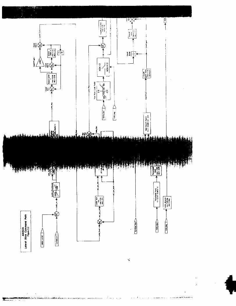
3.3.1 Lateral Stick Command Path
The Lateral Stick Command Path is given in Figure 3.2.
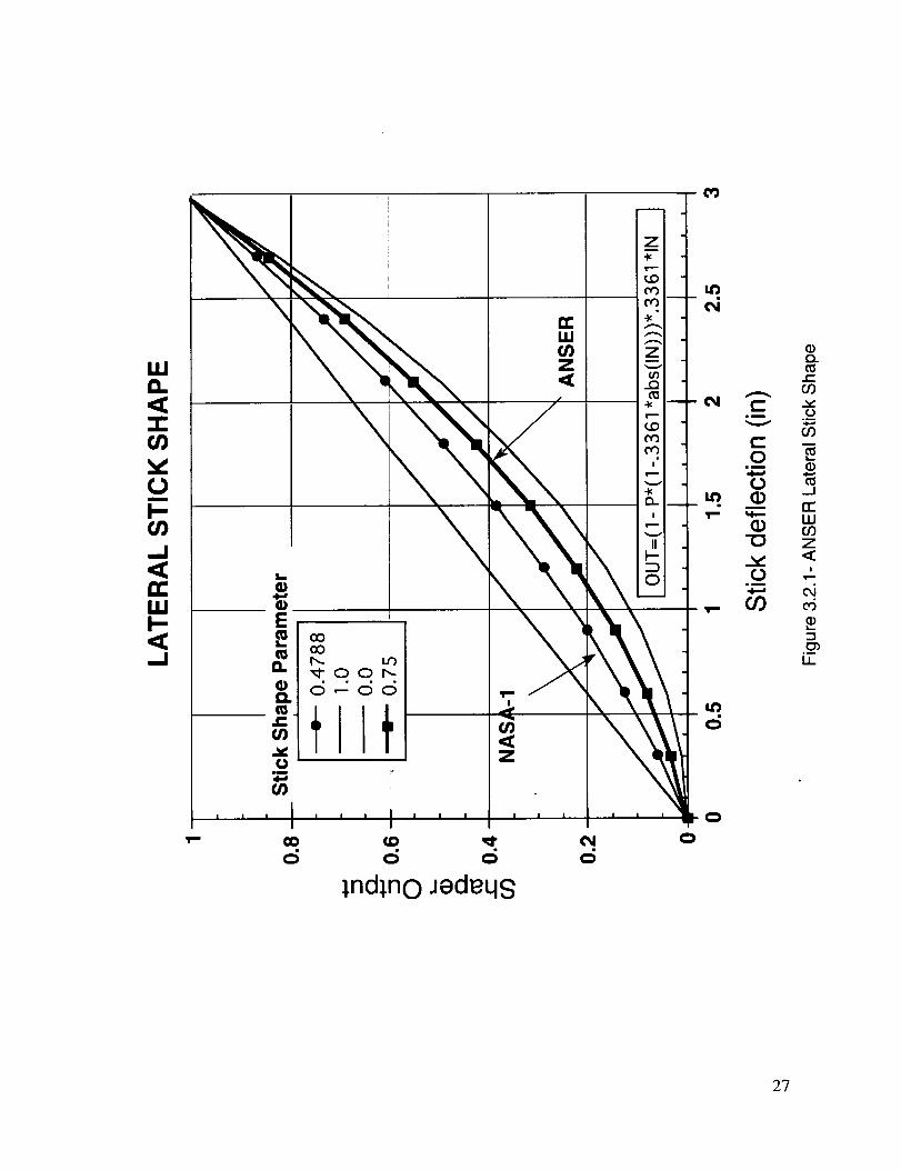
3.3.1.1 Lateral Stick Deadband and Shaping Function
The external lateral stick input is assumed to be bounded to +3.0 inches. Lateral stickexternal input is first passed through a deadband and shaping function. The deadband andshaping function are chosen to provide appropriate stick characteristics to the pilot. Thedeadband is set to _+0.025 inches.
The parabolic shape function is
Output = ( 1.0 - 0.75"( 1.0 - 0.3361 *ABS(Input)))*0.3361 *Input
The shape function normalizes the stick input. The output is bounded to +1.0. Acomparison of the ANSER and NASA-1A lateral stick parabolic shape functions is given in
figure 3.2.1.
3.3.1.2 Stick Coordination
Stick-coordination elements are provided to compensate for the lack of coordination
occurring due to different actuation rates available on the ailerons and rudders. Thiscompensation provides a rate limit, and the feedforward element is added to improve the rollrate response. The rate limit is 0 to maximum lateral stick in 0.25 seconds.
3.3.1.3 Stick Dynamic Limiter and Roll Trim
These elements are designed to reduce sideslip excursions that can occur during aggressiverecoveries from maximum performance rolls where a large stick deflection is used.Functionally these elements allow stick deflections up to 70 percent of full throw to be passeddirectly with larger deflections having the signal passed through a first order lag. This elementshould be disabled for the ANSER flight test. This can be done by changing the internal limitvariable from +/-0. 7 to +/-2.0.
Roll Trim is added to the signal after the stick dynamic limiter. The external roll trim inputis assumed to be bounded to _+0.5 (nondim).
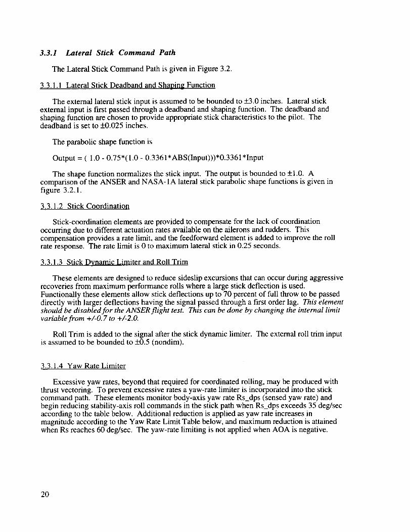
3.3.1.4 Yaw Rate Limiter
Excessive yaw rates, beyond that required for coordinated rolling, may be produced withthrust vectoring. To prevent excessive rates a yaw-rate limiter is incorporated into the stickcommand path. These elements monitor body-axis yaw rate Rs_dps (sensed yaw rate) andbegin reducing stability-axis roll commands in the stick path when Rs_dps exceeds 35 deg/secaccording to the table below. Additional reduction is applied as yaw rate increases inmagnitude according to the Yaw Rate Limit Table below, and maximum reduction is attainedwhen Rs reaches 60 deg/sec. The yaw-rate limiting is not applied when AOA is negative.
20

JF--
li
I
I _ " ji ii


L •
w.
i__!
t/ I
_<_<
i __ ,
' IJ _g'
ttl
• i
-!
z
E 7,.I
t t t_.!tit tr_t'
tlII,
&
I_" Io\
k---
i
t
w_
J|'
E

1
i
._ _,
2]_i
1
f
_,lill
i


F-it
ilD
_u
J.
J
• I
I
I
!|
Jt
i_


Yaw Rate Limit Table
Body Yaw Rate (deg/sec) Gain-100.0 -2.0-60.0 -2.0-35 0.035.0 0.060.0 2.0100.0 2.0
3.3.1.5 Roll Override
Roll-override elements are designed to compensate against pitch-out during rapid rolls.Commanded symmetric stabilator deflection is monitored and compared against a thresholdfunction which is a function of AOA. When the symmetric stabilator becomes saturated, the
lateral stick command is reduced 70 percent.
3.3.1.6 Nz Filter and Adjustment
The sensed Nz signal is passed through a filter to attenuate noise in the signal.
Nz FilterContinuous Form :
Discrete Form (direct Tustin):
s+ 1
One (+1) is added to the filtered Nz signal to yield load factor.
3.3.1.7 Stick Command Gain
The lateral-stick-to-lateral-command gain (pds_max) is a function of available body roll and
yaw control moments. The command gain is calculated in Pseudo Controls. Four functions(AFUNC, TV OFF, FS ON,and GFUNC) adjust the command gain for changes in controlmode (TV,S, or STV), angle of attack, and load factor. These functions are defined by thefollowing tables. Values between design points are determined by linear interpolation.
ANSER AFUNC Table
Angle of Attack (deg) Gain5.0 1.1610.0 1.2415.0 1.420.0 1.725.0 1.930.0 1.735.0 1.1640.0 1.1645.0 1.0450.0 1.1660.0 1.16
25

TV Off Table
Angle of Attack (deg) Gain0.0 0.05.0 0.015.0 -0.335.0 -0.345.0 -0.155.0 0.0100.0 0.0
FS Table
Angle of Attack (deg) Gain0.0 0.1517.0 0.1532.0 0.1590.0 0.15
GFUNC Table
Load Factor (g) Gain0.0 1.01.5 1.03.5 0.359.0 0.35
Note: The FS Table is not required for operation in the TV mode. To hardwire forTV-mode-only operation set control law inputs XTVYAW = 1.0 and XSTRAKE = 0.0. Toreduce code size for TV-mode-only operation delete the FS Table, FSCOMP calculation andset FSCOMP = 1.0.
3.3.1.8 Lateral Stick Cross-Gain
The lateral-stick-to-directional-command gains are functions of angle of attack. Valuesbetween design points are determined by linear interpolation. Gain values at design points are
given in the following tables.
26
!z
LO
Lo
•-o z_
&..I v
I l I I I I I I I I I [ I I I
d d d d
],nd],no Jed_qs
27
Angle of Attack (deg) Gain5.0 -0.020910.0 -0.057515.0 -0.104420.0 -0.125925.0 -0.156030.0 -0.210735.0 -0.239840.0 -0.131845.0 -0.242750.0 -0.376855.0 -0.176960.0 -0.1453
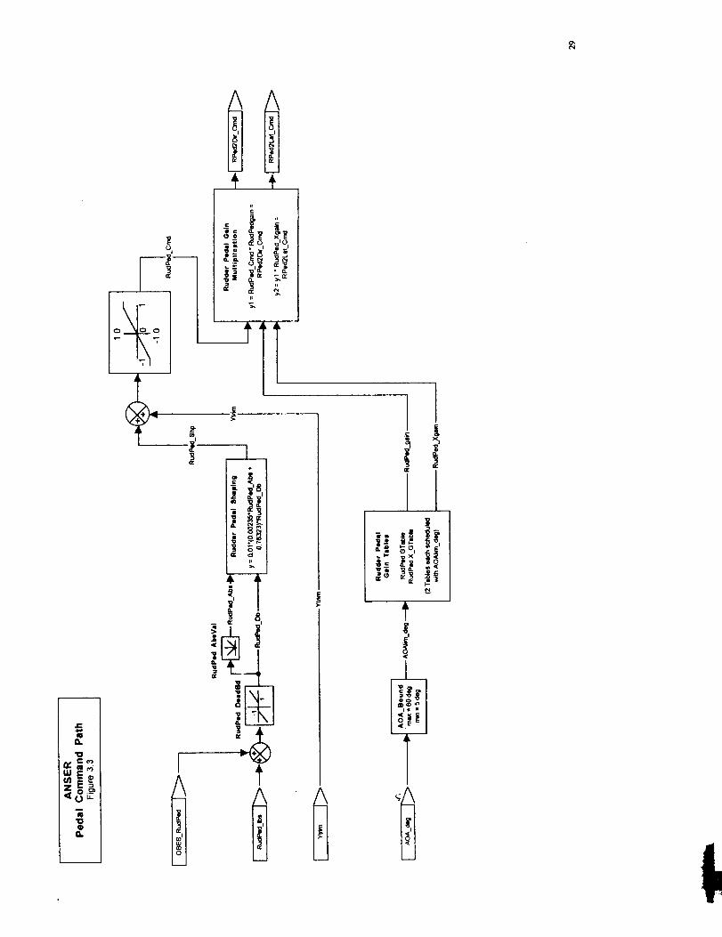
3.3.2 Pedal Command Path
The Pedal Command Path is given in Figure 3.3.
3.3.2.1 Pedal Deadband, Shaping Function, and Yaw Trim
The deadband and shaping function are chosen to provide appropriate pedal characteristicsto the pilot. The external pedal input is assumed to be bounded to +100.0 pounds. Thedeadband is set to +1.0 pounds. The parabolic shape function is the same as in NASA-0.
Output = 0.01*(2.34838e-03*ABS(Input) + 0.763225)*Input
The Yaw Trim signal is added after the pedal shaping function. The external yaw trim inputis assumed to be bounded to _+0.33 (nondim). After addition of the yaw trim, the signal islimited to +1.0.
3.3.2.2 Pedal Command Gain
The pedal directional command gains are functions of angle of attack. Values betweendesign points are determined by linear interpolation. Gain values at design points are given inthe following tables.
Angle of Attack (deg) Gain5.0 0.2610.0 0.2915.0 0.3020.0 0.3725.0 0.4130.0 0.2735.0 0.1840.0 0.2245.0 0.2750.0 0.2355.0 0.2360.0 0.19
28
e,-
eO0,.
m
m0'17-_
_DIU
0
a.
A
I_Ii"
i
u
ii
_._ ._ _
" i iii
It
,_ cp, n
J
A
Ilg
L!
r¢
1_.i _, _-_'.8,:


3.3.2.3 Rudder Pedal Cross-Gain
The rudder-pedal-to-lateral-command gains are functions of angle of attack. Valuesbetween design points are determined by linear interpolation. Gain values at design points aregiven in the following tables. (These gains have been set to zero to improve handling qualitiesas a result of pilot comments during flight testing of the NASA-1A Control Law.)
Angle of Attack (deg) Gain5.0 0.010.0 0.015.0 0.020.0 0.025.0 0.030.0 0.035.0 0.040.0 0.045.0 0.050.0 0.055.0 0.060.0 0.0
3.3.3 Feedback Signal Path
The Feedback Signal Path is shown in Figure 3.4.
3.3.3.1 Filtering, Transformation, and Compensation of Sensed Roll and Yaw Rates
Sensed body-axis roll and yaw rates are converted from (deg/sec) to (rad/sec) and passed
through second-order notch filters to suppress structural modes.
Ps Notch Filter
Continuous Form:
s2+ 2(0.08)(80)s+(80)2s2+ 2(0.7)(80)s+ (80)2
Discrete Form:(Tustin transform, warped to 03=87.0 rad/sec, _n=0.096, _d=0.84)
0.6338z 2 - 0.6376z +0.5392
z 2 -0.6376z +0.1730
31

Rs Notch Filter
Continuous Form:
s 2 + 2(0.08)(150)s +(150) 2
s 2 + 2(0.7)(150)s +(150) 2
Discrete Form:
(Tustin transform, warped to co=218 rad/sec, _n=0.16, _d = 1.40)
0.4935z 2 + 0.2567z + 0.3628
z 2 + 0.2567z - 0.1437
After structural filtering, sensed body-axis roll and yaw rates are transformed to stability-axis rates. Gravity compensation terms are calculated and added to stability-axis yaw rate.
3.3.3.2 Ny Filtering and Offset Correction
The sensed Ny signal is passed through two notch filters to attenuate structural mode
responses .
Ny Notch Filter No. 1
Continuous Form:
s2+ 2(0.04)(58)s+(58)21.4s 2 + 2(0.7)(58)s +(58) 2
Discrete Form:
0.56592338z 2 -0.82529534z + 0.53667645
z 2 - 1.21087437z +0.48817887
Ny Notch Filter No. 2
Continuous Form:
s2 + 2(0.08)(100)s + (100) 2
2s 2 + 2(0.7)(100)s +(100) 2
Discrete Form:
0.46336853z 2 - 0.27160128z + 0.39797629
z2 -0.83807435z+ 0.42781789
A correction term is added to the filtered Ny to compensate for the sensor being located offaxis.
Nyadj_g = Nyfilt_g + 0.02717*(Pbody_rps**2 + Rbody_rps**2)
32

z:
O.
I,D
|w..
lilt1tll
!t
In
t...___J
!
|'
I$
I:1
_ I'
c ,...
I
I
|
t4_
'--"' I _'I._ll I
J_
ii
fl_ I
'""

where Pbody_rps and Rbody_rps are structurally filtered body roll rate and body yaw rate in
(rad/sec), respectively.
3.3.3.3 Ny Interference Correction
A correction term is calculated in Pseudo Controls to compensate for interference
introduced by commanded yaw thrust vectoring and differential strake deflections into themeasured lateral acceleration (Ny) signal. This term is output from Pseudo Controls throughthe Pseudo Controls interface. The interference correction is passed through a notch filter to
suppress structural modes.
Ny-Interference Correction Notch Filter
Continuous Form:
Discrete Form (direct Tustin):
s 2 + 2(0.35)(25)s +(25) 2
s 2 + 2(0.70)(25)s +(25) 2
0.9120z 2 - 1.5695z + 0.7361
z 2 - 1.5695z +0.6481
The filtered interference correction term is subtracted from the offset corrected Ny signal.
Nyfdbk_g = Nyadj_g - Aycorrfilt__g
3.3.3.4 Betadot Feedback Signal
The inertial component of sideslip rate is converted from (deg/sec) to (rad/sec) and passedthrough a second-order notch filter to suppress structural modes.
Continuous Form:
S2 + 2(0.1)(80)s +(80) 2
S2 + 2(0.7)(80)S +(80) 2
Discrete Form:(Tustin transform, warped to 0_=87.0 rad/sec, _n=0.12, _d=0.84)
0.6456z 2 -0.6376z+0.5274
z 2 - 0.6376z +0.1730
The betadot feedback signal is calculated by subtracting stability-axis yaw rate (in units ofrad/sec) from the filtered inertial sideslip-rate signal.
35

3.3.3.5 Roll and Yaw Feedback Gain Tables
The roll and yaw feedback gains are functions of angle of attack. Values between designpoints are determined by linear interpolation. Gain values at design points are given in thefollowing tables.
Roll Feedback Gain Table
AOA (deg) Pstab Rstab Ny Betadot5 -0.6112 -0.7420 -0.0019 -0.382510 -1.3001 -0.9917 -0.1014 -0.185215 -1.5267 -0.8051 -0.0005 -0.643620 -2.0934 -1.4072 -0.6063 -1.232025 -2.2762 -1.1051 0.3622 -1.125730 -1.4900 -1.7434 0.1121 -1.237635 -1.1466 -1.9652 0.5000 -0.906240 -1.0211 -1.3905 1.0000 -0.428945 -0.9574 -0.2758 -0.6353 -1.040050 -0.8741 -0.5382 -0.2759 -0.923155 -0.7002 -0.3071 -0.0952 -0.404860 -0.6523 0.0633 0.0109 0.1267
Yaw Feedback Gain Table
AOA (deg) Pstab Rstab Ny Betadot5 -0.0524 0.1184 0.0524 1.737210 -0.0122 0.1826 0.0607 1.753915 0.0857 0.2316 0.0600 1.593120 0.2006 0.3522 0.2004 1.945125 0.2903 0.4131 0.0183 2.115230 0.1704 0.7166 -0.0254 1.676535 0.1384 0.7926 -1.0000 1.341140 -0.0608 0.4468 -1.5258 1.266945 0.3635 0.1073 -0.2938 1.523750 0.3420 0.3262 0.2016 1.364655 0.1152 0.2536 0.1606 1.061360 0.0801 0.2048 0.0698 0.7430
3.3.3.6 Strake Deployment Compensation
The symmetric strake deployment induces a reduction in system roll damping at high anglesof attack. To compensate for this reduction, terms are multiplied by stability axis yaw rate thenadded to the lateral and directional command channels when the strakes are symmetricallydeployed. The function AOASW adjusts the compensation as a function of angle of attack.This function is defined by the following table. Values between design points are determinedby linear interpolation.
AOASW Table
Angle of Attack (deg) Value0.0 0.0
25.0 0.040.0 2.055.0 0.090.0 0.0
36

Note: The Strake Deployment Compensation is not required for operation in the TV mode. Tohardwire for TV-mode-only operation set control law inputs XTVYA W = 1.0 andXSTRAKE = 0.0. To reduce code size for TV-mode-only operation delete AOASW function;delvlat and delvdir calculations.
3.3.4 Command Summation Block
The Command Summation Block is given in Figure 3.5.
3.3.4.1 Lateral Command Summation and Filtering
The lateral feedback command and lateral strake-deployment-compensation command are
summed to yield the total lateral feedback command. This signal is passed through second-order notch and first-order roll-off filters to suppress structural modes and high-frequencynoise.
Lateral Command Structural FilterContinuous Form:
2Discrete Form (direct Tustin):
0.1834z 2 - 0.028 lz + 0.0282
z 2 - 1.3761z + 0.5596
Lateral Command Roll-Off FilterContinuous Form :
25
s+25
Discrete Form (direct Tustin):z+l
7.4z- 5.4 -
After filtering, the total lateral feedback command is summed with the lateral pilot command
to yield the lateral command.
3.3.4.2 Directional Command Summation and Filtering
The directional feedback command and directional strake-deployment-compensationcommand are summed to yield the total directional feedback command. This signal is passedthrough second-order notch and first-order roll-off filters to suppress structural modes and
high-frequency noise.
37
DirectionalCommandStructuralFilterContinuousForm:
Discrete Form (direct Tustin):
Directional Command Roll-Off FilterContinuous Form :
Discrete Form (direct Tustin):
0.1834z 2 - 0.028 lz + 0.0282
z 2 - 1.3761z + 0.5596
25
s+25
z+l
7.4z-5.4
After filtering, the total directional feedback command is summed with the directional pilotcommand to yield the directional command.
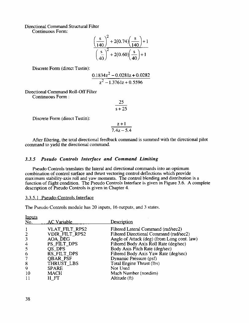
3.3.5 Pseudo Controls Interface and Command Limiting
Pseudo Controls translates the lateral and directional commands into an optimumcombination of control surface and thrust vectoring control deflections which providemaximum stability-axis roll and yaw moments. The control blending and distribution is afunction of flight condition. The Pseudo Controls Interface is given in Figure 3.6. A completedescription of Pseudo Controls is given in Chapter 4.
3.3.5.1 Pseudo-Controls Interface
The Pseudo Controls module has 20 inputs, 16 outputs, and 3 states.
In__No. AC Variable
1 VLAT_FILT_RPS22 VDIR_FILT_RPS23 AOA_DEG4 PS_FILT_DPS5 QS_DPS6 RS_FILT_DPS7 QBAR_PSF8 THRUST_LBS9 SPARE10 MACH
11 H_FT
Description
Filtered Lateral Command (rad/sec2)Filtered Directional Command (rad/sec2)
Angle of Attack (deg) (from Long cont. law)Filtered Body Axis Roll Rate (deg/sec)Body Axis Pitch Rate (deg/sec)Filtered Body Axis Yaw Rate (deg/sec)Dynamic Pressure (psf)Total Engine Thrust (lbs)Not Used
Mach Number (nondim)Altitude (ft)
38

0
"ocelEEo
U
/\
II, i
_:,
EU
I I
o
a.I
, i41--- _ _÷ )41---
A_
t/lI'---i
;_,.,
I$
_ iI _ 'i
4
oI _1 _ i
u
b,.I _
g
'D
"o
CN _ 1,4--
It .i _1I I _ I__1


Inputs (Continued)No. AC Variable12 SINAOA13 COSAOA14 SYMSTAB_DEG15 TVYAW_AUTO16 TVYAW_ON_FLG17 TVROLL_AUTO_FLG18 TVROLL_ON_FLG
19 FS_DEPLOY_LIM20 FS_ON_LIM
DescriptionSine of AOA (nondim)Cosine of AOA (nondim)Commanded Sym Stabilator Deflection (deg)PsC Yaw Thrust Vectoring Control Flag (nondim)PsC Yaw Thrust Vectoring Control Flag (=0) (nondim)PsC Roll Thrust Vectoring Control Flag (=0) (nondim)PsC Roll Thrust Vectoring Control Flag (=0) (nondim)PsC Strake Symmetric Deployment Control Flag (nondim)PsC Differential Strake Control Flag (nondim)
OutputsNo. AC Variable
1 DA_DEG
2 DR_DEG3 DD_DEG4 TVYAW_MP5 TVROLL_MP6 VROLL7 VYAW8 NABYNTV9 STVYAW10 LABYLTV11 STVROLL
12 FSRC_DEG13 FSLC_DEG14 AYCORR_G15 PDSMAX16 SFSYAW
Description
Differential Aileron Deflection (deg)
Rudder Deflection (deg)Differential Stabilator Deflection (deg)Yaw Thrust Vectoring Command (nondim)Roll Thrust Vectoring Command (nondim)Roll Pseudo Control (nondim)Yaw Pseudo Control (nondim)Yaw Moment Available (nondim)
Yaw Thrust Vectoring Engage (nondim)Roll Moment Available (nondim)
Roll Thrust Vectoring Engage (nondim)
Right Strake Deflection (deg)Left Strake Deflection (deg)Lateral Accelerometer Correction (g)Lateral Stick Command Gain (nondim)Differential Strake Engage (nondim)
Roll thrust vectoring (Output 5) is not used, but a capability exists to use this control ifdesired. Outputs 6 through 11 are internal lateral/directional-control-law variables used forperformance monitoring and system diagnostics.
Note: To hardwire for TV-mode-only operation set control law inputs XTVYA W = 1.0 andXSTRAKE = 0.0. Setting XSTRAKE to zero sets Pseudo Control inputsFS_DEPLOY_LIM and FS_ON_LIM to 0.0. When these Pseudo Controls inputs are zero,Pseudo Controls will not use the forebody strakes as a control effector. Pseudo Controls
outputs FSRC_DEG, FSLC_DEG, and SFSYA W will be zero.
3.3.5.2 Control Effector Command Limits
The aerodynamic controls are position limited. The aileron is limited to +25.0 degrees. Therudder is limited to +30.0 degrees. The differential stabilator is limited to +10. degrees. Theright and left strake commands are each limited to 0.0 to +90.0 degrees. The yaw thrust-vectoring signal is a Mixer/Predictor command and is not limited.
Note: The right and left strake command deflection limits are not required for operation in theTV mode. To hardwire for TV-mode-only operation set control law inputs XTVYA W = 1.0and XSTRAKE = 0.0. To reduce code size for TV-mode-only operation delete left and rightdeflection limits and set strake deflection outputs to 0.0.
43

3.3.5.3 Aileron Trailing-Edge-Down Deflection Limit
The trailing-edge-down deflection of the left and right ailerons are limited at high angle ofattack to reduce potential problems due to adverse yaw. The aileron trailing-edge-downdeflection limit is given in Figure 3.7. The limit is a function of angle of attack. Below 30degrees AOA the trailing-edge-down deflection is not limited. The trailing-edge-downdeflection is limited to 25 degrees at 30 degrees AOA and decreases linearly to a limit of 8degrees at 55 degrees AOA. Above 55 degrees AOA the trailing-edge-down deflection islimited to 8 degrees. However, if the OBES l is engaged, the trailing-edge-down deflection islimited to 25 degrees at all angles of attack.
3.3.5.4 Strake Linearizing Function
A third-order-polynomial linearizing function is included after the strake command limiter tocorrect for a nonlinearity in the strake actuator transfer function.
3.3.6 Mode Switching Logic
The Mode Switching Logic is shown in figure 3.8.
The mode switching logic performs two functions. First, the logic translates externalmode-control inputs into internal control-law mode-control variables. Secondly, it preventsabrupt changes in control mode by ramping in changes over a specified period of time.Changes in the yaw thrust vectoring are ramped in over one second. Changes in the forebodystrake are ramped in over two seconds (symmetric strake deployment during the first second,differential strake deflections during the remaining second)
The mode switching is controlled by the external input signals XSTRAKE andXTVYAW (Inputs 18 and 27, respectively). Input values for XTVYAW and XSTRAKE toengage the different control law modes are given in the following table.
Mode XTVYAW XSTRAKETV 1.0 0.0S 0.0 2.0STV 1.0 2.0
Note: The forebody strake switching logic is not required for operation in the TV mode. Tohardwire for TV-mode-only operation set control law inputs XTVYA W = 1.0 andXSTRAKE = 0.0. To reduce code size for TV-mode-only operation, delete forebodystrake-switching logic, and set FS_DEPLOY_LIM and FS_ON_LIM to 0.0.
I The OBES (On-Board Excitation System) is a software-implemented system to produce precision computer-
generated commands for input into the RFCS for accurate control of maneuvers.
44

So_
._E-/
LUu_,
z_,?c
o_o
0
zac,.,
|a I
I
U'J
/
f -°M'J
4,
T
'o
_-]i v
L E] +iiI


.J
z._S;, _
' qa
0:E
!
A
= ,
wO
!
1
4e
fil I
D
tttlfill


3.4 Control Law Inputs and Outputs
The lateral/directional control law has 32 inputs, 29 outputs, and 32 states.
In__utsNo. AC Variable
1 LATST_IN2 NY_G3 PS_DPS4 RS_DPS5 BDOTINERT_DPS6 RUDPED_LBS7 AOA_DEG**
8 QS_DPS9 OBES_LATST10 QCFILTER2_PSF11 COSTHETA
12 FGTOTL_LB S13 FGTOTR_LB S14 YTRIM15 RTRIM16 MACH
17 H_FT18 XSTRAKE
19 NZ_G20 SYMSTAB_DEG**21 VTRUE_FPS22 SINPHI
23 OBES_RudPed24 SINALPHA**25 COSALPHA**26 STKNLG*27 XTVYAW
28 OBE_DIFFER_STAB_CMDt
29 OBE_RUDDER_CMDt
30 OBE_AILERON_CMDt
31 OB E_RIGHT_STRAKE_CMDt
32 OB E_LEFT_STRAKE_CMD t
Description
Lateral Stick (in.) (-3 to +3)Sensed Lateral Acceleration (g)Sensed Body Axis Roll Rate (deg/sec)Sensed Body Axis Yaw Rate (deg/sec)Inertial component of Sideslip Rate (deg/sec)Rudder Pedal (lbs) (-100 to + 100)
Angle of Attack (deg)Sensed Body Axis Pitch Rate (deg/sec)OBES lateral stick (nondim) (-1 to +1)
Filtered Impact Pressure (psf)Cosine of INS Theta
Left Engine Thrust (lbs)Right Engine Thrust (lbs)Yaw Trim Input (nondim) (-0.33 to +0.33)Roll Trim Input (nondim) (-0.5 to +0.5)Mach Number (nondim)Altitude (above sea level) (ft)Forebody Strake Control Flag (0,1, or 2)Sensed Normal Acceleration (g)Commanded Sym Stabilator Deflection (deg)True Velocity (fps) (from Long cont. law)Sine of INS Phi
OBES rudder pedal (nondim) (- 1 to + 1)Sine of AlphaCosine of AlphaStrake Non-Linearity Gearing Switch*Yaw Vectoring Control Flag (0 or 1)
OBES Differential Stabilator Command (deg)
OBES
OBES
OBES
OBES
Rudder Command (deg)
Differential Aileron Command (deg)
Right Strake Command (deg)
Left Strake Command (deg)
* Simulation use only. ** From Longitudinal Control Law
t Not present in all simulations
OutputsNo. AC Variable
1 DD_LIM_DEG2 DA_LIM_DEG3 DL_DEG4 DF_DEG5 DR_LIM_DEG6 TVYAW_MP
Description
Differential Stabilator Deflection (deg)Differential Aileron Deflection (deg)
Diff Leading Edge Flap Deflection (deg)Diff Trailing Edge Flap Deflection (deg)Differential Rudder Deflection (deg)Yaw Thrust Vector Command (nondim)
49

Outputs (Continued)No. AC Variable7 VROLL8 VYAW
9 LAT_CMD_RPS210 DIR_CMD_RPS211 LATST_CMD12 TVROLL_MP13 NYADJ_G
14 RSTABCOR_DPS15 FSRC_LIM_DEG16 FSLC_LIM_DEG17 NABYNTV18 LABYLTV
19 GCOMP_RPS20 THRUST_LBS21 AYCORR_G22 PDSMAX23 STVYAW24 SFSYAW
25 TVYAW_AUTO26 FS_ON_LIM27 FS_DEPLOY_LIM28 BDOTINERT_DPS29 BDOT_DPS
DescriptionRoll Pseudo Control (nondim)Yaw Pseudo Control (nondim)Lateral Command (rad/sec2)Directional Command (rad/sec2)Lateral Stick Command (nondim)Roll Thrust Vector Command (nondim)
Adjusted lateral acceleration (g)Compensated Rstab (deg/sec)Right Forebody Strake Command (deg)Left Forebody Strake Command (deg)Yaw Moment Available (nondim)Roll Moment Available (nondim)
Gravity Compensation (rad/sec)Total Thrust (lbs)Lateral Accelerometer Correction (g)Lateral Stick Command Gain (nondim)
Yaw Thrust Vectoring Engage (nondim)Differential Strake Engage (nondim)PsC Yaw Thrust Vectoring Control FlagPsC Differential Strake Control FlagPsC Strake Symmetric Deployment Control FlagInertial component of Sideslip Rate (deg/sec)Sideslip Rate (deg/sec)
Outputs 7 through 14 and 17 through 29 are internal Lateral/Directional Control Law variablesused for performance monitoring and system diagnostics.
Note • To hardwire for TV-mode-only operation set control law inputs XTVYA W = 1.0 andXSTRAKE = 0.0.
3.2
3.3
3.4
3.5
References
Lallman, Frederick J.: Relative Control Effectiveness Technique With Application toAirplane Control Coordination. NASA TP 2416, April 1985.
Lallman, Frederick J.: Preliminary Design Study of a Lateral-Directional Control SystemUsing Thrust Vectoring. NASA TM 86425, November 1985.
Murphy, Patick C.and Davidson, John B." Control Design for Future Agile Fighters.Presented at 1991 AIAA Atmospheric Flight Mechanics Conference, held in New Orleans,
LA, August 19-21, 1991. AIAA Paper No. 91-2882, 1991.
Schmidt, David K.; and Davidson, John B.: Synthesis and Analysis of a Modal ControlLaw for an Aeroelastic Vehicle. Presented at AIAA Guidance, Navigation, and ControlConference, Snowmass, Colorado. AIAA Paper No. 85-1898. August 1985.
Davidson, John B.; and Schmidt, David K.: Flight Control Synthesis for Flexible AircraftUsing Eigenspace Assignment. NASA CR-178164. June 1986.
50

Chapter 4
Lateral/Directional Pseudo
Version 151
Controls
4.1 General
This chapter contains equations, diagrams, and tables that define the Pseudo Controls
portion of the ANSER Lateral/Directional Control Law for the HARV airplane. A developmentof the Pseudo Controls methodology can be found in reference 4.1, and its application to thelateral/directional control of a high performance fighter can be found in reference 4.2. Themethodology described in the references was modified for use in the ANSER Control Law
design.
The purpose of Pseudo Controls is to distribute lateral/directional commands in a near-optimal fashion to the appropriate control effectors. A benefit of the technique is that thefeedback controller is required to generate fewer outputs (commands), and thus the number of
feedback gains is reduced. In the ANSER Pseudo Controls, stability-axis roll and yaw angularacceleration commands from the Lateral/Directional Feedback Control Law are processed to
generate deflection commands to the three aerodynamic control surface actuators (aileron,rudder, and differential stabilator), roll and yaw commands to the thrust-vectoring system, and
yaw commands to the forebody strakes as in figure 4.1.
This specification includes modifications to the NASA-1A Control Law to includeforebody strake controls, a calculation of the available stability-axis roll acceleration,calculations of the interference of forebody strake and yaw thrust-vectoring forces in the lateralaccelerometer, and a modification to account for a + 10 degree limit on differential stabilator
commands in the flight computer.
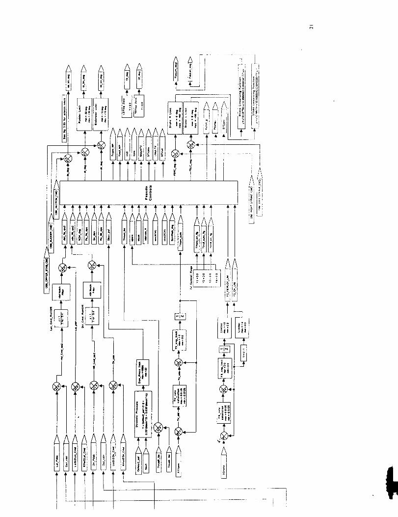
The HARV Pseudo Controls are divided into an Interconnect and a Distributor, and
functional block diagrams of these are shown in figures 4.2 and 4.3, respectively (A morecomprehensive diagram is presented in section 4.3). The Interconnect converts the stability-axis roll and yaw angular acceleration commands into body-axis roll and yaw angularacceleration commands, provides compensation for inertial coupling, provides compensationfor the roll moment produced by yaw thrust vectoring due to the engine nozzle displacement inthe z-direction, and outputs roll and yaw commands in the form of Pseudo Control variables.These Pseudo Control variables are the commanded, normalized body-axis roll and yawmoments, that is, the fraction of the available full-scale roll and yaw moments, which are alsocalculated in the Interconnect as functions of angle of attack, airspeed, altitude, Mach number,and symmetric stabilator deflection. The Interconnect also provides logic to engage the thrust-vectoring controls as a function of engine power and flight condition. Thrust vectoring can bedisabled by an external input signal.
The Distributor apportions the roll and yaw commands to the aerodynamic surfaces and tothe thrust-vectoring system (Mixer/Predictor) according to the effectiveness of the controlscomputed as functions of angle of attack and symmetric stabilator deflection and according tothe thrust-vectoring engage signal from the Interconnect. To prevent overheating of the thrust-vectoring vanes, the Distributor provides vane-relief logic to transfer slowly-varying andsteady-state thrust-vectoring commands to the aerodynamic control surfaces. Thrust vectoringis always used for transient maneuvers when permitted by the yaw thrust-vector engagementlogic, and thrust vectoring is used in steady state when the aerodynamic surfaces cannot supplythe required moments.
Forebody strake controls are deployed and engaged by setting external control inputs. Theyaw moment capability of the strakes is included in the calculation of the yaw Pseudo Control,
51
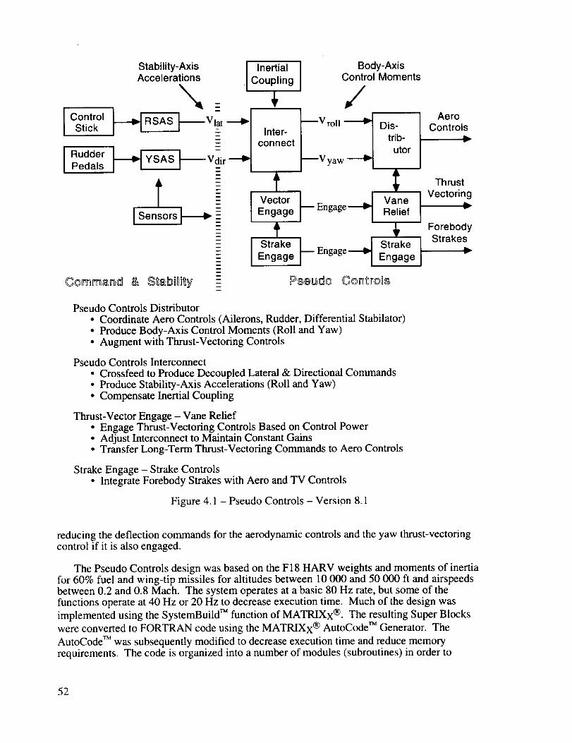
ControlStick
I RudderPedals
Stability-Axis I InertialAccelerations Coupling
_t
Inter-connect
I,/
Body-AxisControl Moments
mVroll
--V yaw
Dis-trib-
utor
I Vect°r I__ --_t vaneEngage Engage Relief
Strake ]
Engage I
Pseudo Controls Distributor
• Coordinate Aero Controls (Ailerons, Rudder, Differential Stabilator)• Produce Body-Axis Control Moments (Roll and Yaw)
• Augment with Thrust-Vectoring Controls
Pseudo Controls Interconnect
• Crossfeed to Produce Decoupled Lateral & Directional Commands• Produce Stability-Axis Accelerations (Roll and Yaw)• Compensate Inertial Coupling
Thrust-Vector Engage - Vane Relief• Engage Thrust-Vectoring Controls Based on Control Power• Adjust Interconnect to Maintain Constant Gains• Transfer Long-Term Thrust-Vectoring Commands to Aero Controls
Strake Engage - Strake Controls• Integrate Forebody Strakes with Aero and TV Controls
Figure 4.1 - Pseudo Controls - Version 8.1
AeroControls
ThrustVectoring
v
ForebodyStrakes
reducing the deflection commands for the aerodynamic controls and the yaw thrust-vectoringcontrol if it is also engaged.
The Pseudo Controls design was based on the F 18 HARV weights and moments of inertiafor 60% fuel and wing-tip missiles for altitudes between 10 000 and 50 000 ft and airspeedsbetween 0.2 and 0.8 Mach. The system operates at a basic 80 Hz rate, but some of the
functions operate at 40 Hz or 20 Hz to decrease execution time. Much of the design was
implemented using the SystemBuild TM function of MATRIXx ®. The resulting Super Blocks
were converted to FORTRAN code using the MATRIXx ® AutoCode TM Generator. The
AutoCode TM was subsequently modified to decrease execution time and reduce memoryrequirements. The code is organized into a number of modules (subroutines) in order to
52

IIARV ANSER Ctmtrol La.',_
_)
t_
o
U
Lt.IkJ
0UkG.J
ci
t.I
hi)
53

llARI/ ANSER Control Laws
°_
C_
0° _,,_
0
C3!
_4
bllol,,_
(
I
54

1) collect sections of code together into functional units, 2) facilitate multirate operation, and
3) enable detailed checkout.
The remainder of this section contains a brief description of the modules and the multirate
timing for the modules. Section 4.2 contains a detailed description of each module includingequations, tables, and diagrams. Section 4.3 contains overall (horizontal) block diagrams andinput/output lists for the complete Pseudo Controls System.
4.1.1 Modules
The top-level module of the Pseudo Controls system is named AC_PSEUDO_CONTROLSand is assigned the subroutine name USR39FJL in the LaRC implementation. This modulecalls the other modules as subroutines except for DX_YAW_VANE_RELIEF (USR54FJL)and DX_ROLL_VANE_RELIEF (USR53FJL) which are called by AC_DISTRIBUTOR
(USR38FJL). The modules are listed with brief descriptions below.
Modules
Name Subroutine DescriptionAC_PSEUDO_CONTROLS USR39FJL Top level module to convert roll and
yaw acceleration commands into
control deflection an_les.USRCKFJL Multi-phase clock provides signals to
enable selected modules at 40 Hz and20 Hz rates.
DX_FYAW_FUNCTION* USR33FJL
DX_FROLL_FUNCTION* USR34FJL
DX_DISTRIBUTOR_GAINS* USR36FJL
Calculates available yaw moment
coefficient for primar), controls.Calculates available roll moment
coefficient for primary controls.
Calculates gains to distribute roll andyaw commands among primarycontrols.
DX STRAKE ENGAGE* USR59FJL Engagement control for forebody- - strakes.
DX_YAWTV_ENGAGE* USR52FJL Engagement control for yaw thrust-vectorin_ controls.Engagement control for roll thrust-
vectorin_ controls.Interconnects lateral and directional
controls to produce roll and yawcontrols.
DX_ROLLTV_ENGAGE* USR51FJL
DX_INTERCONNECT* USR35FJL
AC_DISTRIBUTOR* USR38FJL Distributes roll and yaw controlsamong primary and thrust-vectoringcontrols.
DX_YAW_VANE_RELIEFt USR54FJL
DX_ROLL_VANE_RELIEFt" US R53FJL
DX_STRAKE_CONTROLS* USR58FJL
* module called by AC_PSEUDO_CONTROLS
Replaces yaw thrust-vectoring by
primary controls when possible.Replaces roll thrust-vectoring by
primary controls when possible.Generates position commands for
forebody strakes.
? module called by AC_DISTRIBUTOR
55
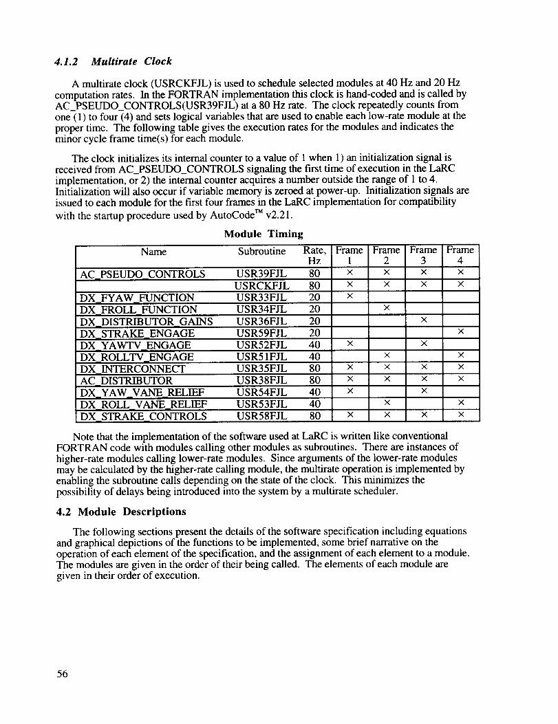
4.1.2 Multirate Clock
A multirate clock (USRCKFJL) is used to schedule selected modules at 40 Hz and 20 Hz
computation rates. In the FORTRAN implementation this clock is hand-coded and is called byAC_PSEUDO_CONTROLS(USR39FJL) at a 80 Hz rate. The clock repeatedly counts from
one (1) to four (4) and sets logical variables that are used to enable each low-rate module at theproper time. The following table gives the execution rates for the modules and indicates theminor cycle frame time(s) for each module.
The clock initializes its internal counter to a value of 1 when 1) an initialization signal isreceived from AC_PSEUDO_CONTROLS signaling the first time of execution in the LaRC
implementation, or 2) the internal counter acquires a number outside the range of 1 to 4.Initialization will also occur if variable memory is zeroed at power-up. Initialization signals areissued to each module for the first four frames in the LaRC implementation for compatibility
with the startup procedure used by AutoCode TM v2.21.
Module Timing
Name Subroutine Rate, Frame Frame Frame FrameHz I 2 3 4
AC_PSEUDO_CONTROLS USR39FJL 80 × × × ×USRCKFJL 80 x × x ×
DX_FYAW_FUNCTION USR33FJL 20 x
DX_FROLL_FUNCTION USR34FJL 20
DX_DISTRIBUTOR_GAINS USR36FJL 20
DX_STRAKE_ENGAGE
DX_YAWTV_ENGAGE
DX_ROLLTV ENGAGE
DX_INTERCONNECT
×
×
AC_DISTRIBUTORDX_YAW_VANE_RELIEF
DX_ROLL_VANE_RELIEF
DX_STRAKE_CONTROLS
USR59FJL 20 ×
USR52FJL 40 x x
USR51FJL 40 x x
USR35FJL 80 x x x x
USR38FJL 80 x x x x
USR54FJL 40 x x
USR53FJL 40 x x
USR58FJL 80 x x x x
Note that the implementation of the software used at LaRC is written like conventional
FORTRAN code with modules calling other modules as subroutines. There are instances of
higher-rate modules calling lower-rate modules. Since arguments of the lower-rate modulesmay be calculated by the higher-rate calling module, the multirate operation is implemented byenabling the subroutine calls depending on the state of the clock. This minimizes thepossibility of delays being introduced into the system by a multirate scheduler.
4.2 Module Descriptions
The following sections present the details of the software specification including equationsand graphical depictions of the functions to be implemented, some brief narrative on theoperation of each element of the specification, and the assignment of each element to a module.The modules are given in the order of their being called. The elements of each module aregiven in their order of execution.
56
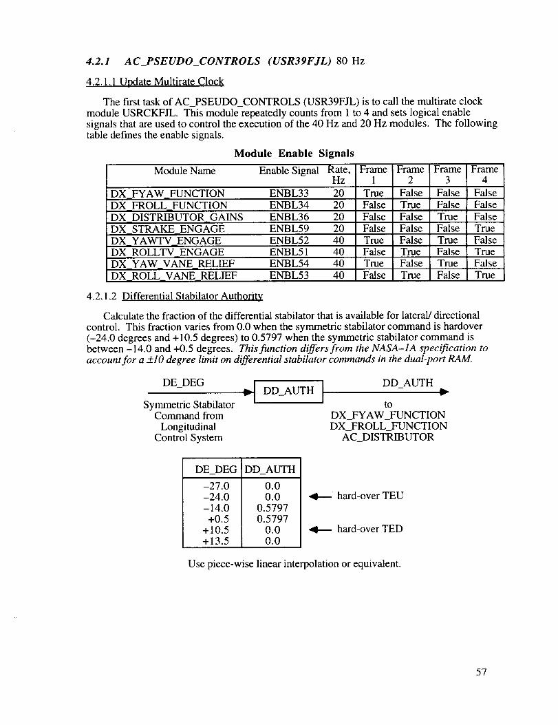
4.2.1 AC_PSEUDO_CONTROLS (USR39FJL) 80 Hz
4.2.1.1 Update Multirate Clock
The first task of AC_PSEUDO_CONTROLS (USR39FJL) is to call the multirate clockmodule USRCKFJL. This module repeatedly counts from 1 to 4 and sets logical enable
signals that are used to control the execution of the 40 Hz and 20 Hz modules. The followingtable defines the enable signals.
Module Enable Signals
Module Name Enable Signal Rate, Frame Frame Frame FrameHz 1 2 3 4
DX_FYAW FUNCTION ENBL33 20 True False False False
DX_FROLL FUNCTION ENBL34 20 False True False FalseDX_DISTRIBUTOR_GAINS ENBL36 20 False False True False
DX_STRAKE_ENGAGE ENBL59 20 False False False True
DX_YAWTV ENGAGE ENBL52 40 True False True False
DX_ROLLTV_ENGAGE ENBL51 40 False True False TrueDX_YAW_VANE_RELIEF ENBL54 40 True False True False
DX_ROLL_VANE_RELIEF ENBL53 40 False True False True
4.2.1.2 Differential Stabilator Authority
Calculate the fraction of the differential stabilator that is available for lateral/directional
control. This fraction varies from 0.0 when the symmetric stabilator command is hardover(-24.0 degrees and +10.5 degrees) to 0.5797 when the symmetric stabilator command isbetween -14.0 and +0.5 degrees. This function differs from the NASA-1A specification toaccount for a +_10 degree limit on differential stabilator commands in the dual-port RAM.
DE_DEG ,..I DD AUTH [ DD_AUTHv I - j •
Symmetric Stabilator toCommand from DX_FYAW_FUNCTION
Longitudinal DX_FROLL_FUNCTIONControl System AC_DISTRIBUTOR
DE_DEG DD_AUTH
-27.0-24.0-14.0
+0.5+10.5+13.5
0.00.0
0.5797
0.57970.00.0
•4----- hard-over TEU
hard-over TED
Use piece-wise linear interpolation or equivalent.
57

4.2.1.3 Subroutine Calls
40 Hz Modules -
80 Hz Modules -
Execute modules (subroutines) depending on multirate clock state.20 Hz Modules - Call DX_FYAW_FUNCTION(USR33FJL) if ENBL33 is true.
Call DX_FROLL_FUNCTION(USR34FJL) if ENBL34 is true.Call DX_DISTRIBUTOR_GAINS(USR36FJL) if ENBL36 is true.Call DX_STRAKE_ENGAGE(USR59FJL) if ENBL59 is true.
Call DX_YAWTV_ENGAGE(USR52FJL) if ENBL52 is true.Call DX_ROLLTV_ENGAGE(USR51FJL) if ENBL51 is true.
Call DX_INTERCONNECT(USR35FJL) each frame.Call AC_DISTRIBUTOR(USR38FJL)* each frame.Call DX_STRAKE_CONTROLS(USR58FJL) each frame.
* DX_YAW_VANE_RELIEF(USR54FJL) and DX_ROLL_VANE_RELIEF(USR53FJL)are called from AC_DISTRIBUTOR(USR38FJL) at 40 Hz.
4.2.1.4 Thrust-Vector Scaling
The roll and yaw thrust-vector commands are adjusted by estimated engine thrust (two-engine sum) for compatibility with the scaling of the Mixer/Predictor.
TVYAW_DEG
from
AC_DISTRIBUTOR
THRUST (lb) d THRUST
-I 15000
TVROLL_DEG
from
AC_DISTRIBUTOR
1
rid
TVYAW_MP
TVROLL_MP
4.2.1.5 Accelerometer Correction
The interference of the research controls in the lateral accelerometer output AY_CORR_G
as calculated by summing the interference caused by the forebody strake controlsFS_CORR_G and the yaw thrust-vectoring controls TV_CORR_G. The output of theaccelerometer may be corrected by subtracting AY_CORR_G from it.
TV_CORR_G from AC_DISTRIBUTOR + _+FS CORR G from DX STRAKE CONTROLS*
AY_CORR_G ,,..._
( g units )
* equals zero for NASA-1A
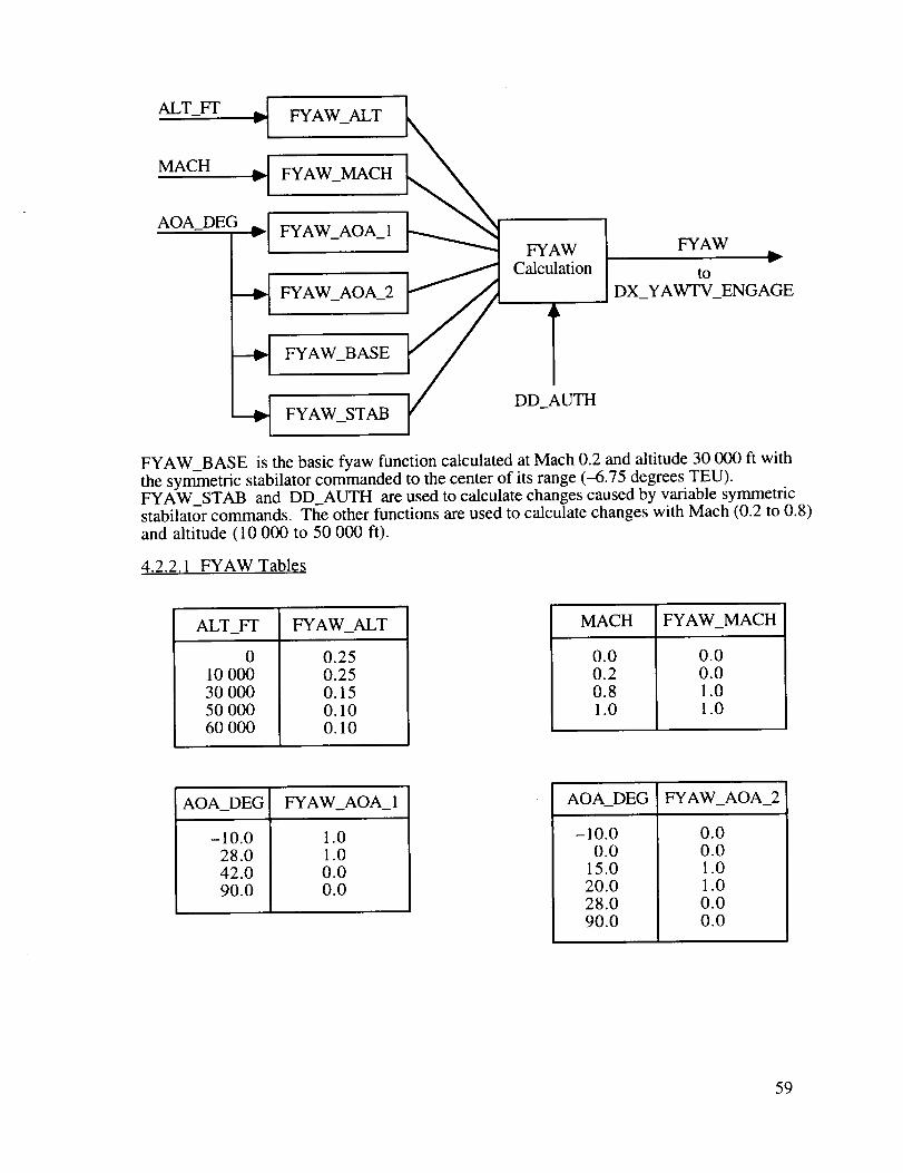
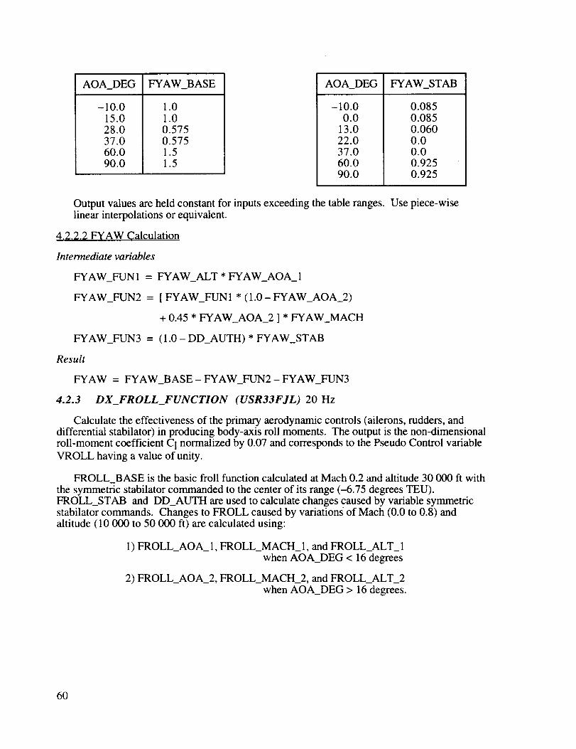
4.2.2 DX_FYA W_FUNCTION (USR33FJL) 20 Hz
Calculate the effectiveness of the primary aerodynamic controls (ailerons, rudders, anddifferential stabilator) in producing body-axis yaw moments. The output is the non-
dimensional yaw-moment coefficient C n normalized by 0.04 and corresponds to the Pseudo
Control variable VYAW having a value of unity.
58
ALT_FT I_ FYAW_ALT
MACH_ FYAW_MACH
AOA_DEG _[ FYAW_AOA_I
---_ FYAW_AOA_2
--_ FYAW_BASE
--_ FYAW_STAB
FYAWCalculation
TDD_AUTH
FYAWv
to
DX_YAWTV_ENGAGE
FYAW BASE is the basic fyaw function calculated at Mach 0.2 and altitude 30 000 ft with
the syrn_netric stabilator commanded to the center of its range (-6.75 degrees TEU).FYAW STAB and DD_AUTH are used to calculate changes caused by variable symmetricstabilator commands. The other functions are used to calculate changes with Mach (0.2 to 0.8)
and altitude (10 000 to 50 000 ft).
4.2.2.1 FYAW Tables
ALT_FT FYAW_ALT
010 00030 00050 00060 000
0.250.250.150.100.10
MACH FYAW_MACH
0.00.20.81.0
0.00.01.01.0
AOA_DEG FYAW_AOA_I
-10.028.042.090.0
1.01.00.00.0
AOA_DEG FYAW_AOA_2
-10.00.0
15.020.028.090.0
0.00.01.01.00.00.0
59
AOA_DEG FYAW_BASE
-10.015.028.037.060.090.0
1.01.00.5750.5751.51.5
AOA_DEG FYAW_STAB
-10.00.0
13.022.037.060.090.0
0.0850.0850.0600.00.00.9250.925
Outputvaluesareheldconstantfor inputsexceedingthetableranges.Uselinearinterpolationsorequivalent.
4.2.2.2 FYAW Calculation
Intermediate variables
FYAW_FUN 1 =
FYAW_FUN2 =
FYAW_FUN3 =
Result
piece-wise
FYAW_ALT * FYAW_AOA_ 1
[ FYAW_FUN1 * (1.0 - FYAW_AOA_2)
+ 0.45 * FYAW_AOA_2 ] * FYAW_MACH
(1.0 - DD_AUTH) * FYAW_STAB
FYAW = FYAW_BASE - FYAW_FUN2 - FYAW_FUN3
4.2.3 DX_FROLL_FUNCTION (USR33FJL) 20 Hz
Calculate the effectiveness of the primary aerodynamic controls (ailerons, rudders, anddifferential stabilator) in producing body-axis roll moments. The output is the non-dimensionalroll-moment coefficient C 1 normalized by 0.07 and corresponds to the Pseudo Control variable
VROLL having a value of unity.
FROLL_BASE is the basic froll function calculated at Mach 0.2 and altitude 30 000 fi with
the symmetric stabilator commanded to the center of its range (-6.75 degrees TEU).FROLL_STAB and DD_AUTH are used to calculate changes caused by variable symmetricstabilator commands. Changes to FROLL caused by variations _of Mach (0.0 to 0.8) andaltitude (10 000 to 50 000 ft) are calculated using:
1) FROLL_AOA_I, FROLL_MACH_I, and FROLL_ALT_Iwhen AOA_DEG < 16 degrees
2) FROLL_AOA_2, FROLL_MACH_2, and FROLL_ALT_2
when AOA_DEG > 16 degrees.
6O
ALT_Fr ,d FROLL_ALT_ 1
_ FROLL_ALT_2
MACH "-[ FROLL_MACH_I
_ FROLL_MACH_2
AOA_DE_
FROLL_AOA_I
FROLL_AOA_2
FROLL_BASE
FROLL_STAB
FYAWCalculation
DD_AUTH
FROLLv
to
DX_ROLLTV_ENGAGE
4.2.3.1 FROLL Tables
AOA_DEG FROLL_AOA_I
-10.0
7.016.090.0
1.0
1.00.00.0
MACH FROLL_MACH_I
0.000.250.801.00
0.0
0.01.01.0
ALT_FT FROLL_ALT_ 1
010 00050 00060 000
0.4430.4430.2000.200
MACH FROLL_MACH_2
0.000.200.631.00
0.00.01.01.0
61

AOA_DEG FROLL_AOA_2
-10.016.032.044.060.068.090.0
0.00.01.00.20.20.00.0
AOA_DEG FROLL_BASE
-10.010.020.032.044.060.090.0
1.001.000.640.600.290.140.14
ALT_FT FROLL_ALT_2
0100005000060000
0.3080.3080.2620.262
AOA_DEG
-10.08.0
28.038.054.090.0
FROLL_STAB
0.080.080.160.140.000.00
Outputvaluesareheldconstantfor inputsexceedingthetableranges.Usepiece-wiselinearinterpolationsor equivalent.
4.2.3.2 FROLL Calculation
Intermediate variables
FROLL_FUN1 = FROLL_AOA_I * FROLL_MACH_I * FROLL_ALT_I
FROLL_FUN2 = FROLL_AOA_2 * FROLL_MACH_2 * FROLL_ALT_2
FROLL_FUN3 = (1.0 - DD_AUTH) * FROLL_STAB
Result
FROLL = FROLL_BASE - FROLL_FUN 1 - FROLL_FUN2 - FROLL_FUN3
4.2.4 DX_DISTRIBUTOR_GAINS (USR36FJL) 20 Hz
Calculate the gains used to distribute Pseudo Controls VROLL and VYAW to the
primary aerodynamic controls (ailerons, rudders, and differential stabilator). Use piece-wiselinear interpolation or equivalent.
4.2.4.1 Roll Distributor Gains
Calculate the distributor gains used to command body-axis roll moments according to
VROLL signals.
62
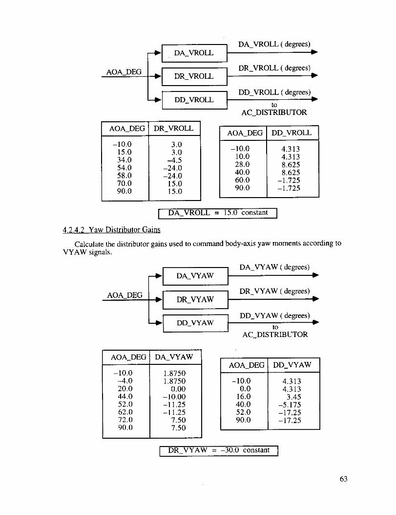
AOA_DEG :IDA_VROLL I
DR_VROLL I
DD_VROLL
AOA_DEG DR_VROLL
-10.015.0
34.054.058.070.090.0
3.03.0
-4.5-24.0-24.0
15.015.0
DA_VROLL (degrees)v
DR_VROLL (degrees)
DD_VROLL (degrees)
to
AC_DISTRIBUTOR
AOA_DEG DD_VROLL
-10.010.0
28.040.060.090.0
4.3134.3138.6258.625
-1.725-1.725
[ DA_VROLL = 15.0 constant I
4.2.4.2 Yaw Distributor Gains
Calculate the distributor gains used to command body-axis yaw moments according to
VYAW signals.
AOA_DEG
--I Aw I--I DR_AwL-'1 o w I
DA_VYAW (degrees)
DR_VYAW (degrees)
DD_VYAW (degrees)
tO
AC_DISTRIBUTOR
v
w
v
AOA_DEG DA_VYAW
-10.0-4.020.044.052.062.072.090.0
1.87501.8750
0.00-10.00-11.25-11.25
7.507.50
AOA_DEG DD_VYAW
-10.00.0
16.040.052.090.0
4.3134.313
3.45-5.175-17.25-17.25
I DR_VYAW = -30.0 constant I
63
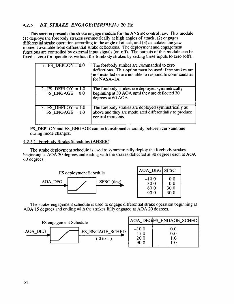
4.2.5 DX_STRAKE_ENGAGE(USR59FJL) 20 Hz
This section presents the strake engage module for the ANSER control law. This module(1) deploys the forebody strakes symmetrically at high angles of attack, (2) engagesdifferential strake operation according to the angle of attack, and (3) calculates the yawmoment available from differential strake deflections. The deployment and engagementfunctions are controlled by external input signals (on-off). The outputs of this module can be
fixed at zero for operations without the forebody strakes by setting these inputs to zero (off).
1. FS_DEPLOY = 0.0
,
,
FS_DEPLOY = 1.0FS_ENGAGE = 0.0
FS_DEPLOY = 1.0FS_ENGAGE = 1.0
The forebody strakes are commanded to zerodeflections. This option must be used if the strakes arenot installed or are not able to respond to commands asfor NASA- 1A
The forebody strakes are deployed symmetricallybeginning at 30 AOA until they are deflected 30degrees at 60 AOA.
The forebody strakes are deployed symmetrically as
above and they are modulated differentially to producecontrol moments.
FS_DEPLOY and FS_ENGAGE can be transitioned smoothly between zero and one
during mode changes.
4.2.5.1 Forebody Strake Schedules (ANSER)
The strake deployment schedule is used to symmetrically deploy the forebody strakesbeginning at AOA 30 degrees and ending with the strakes deflected at 30 degrees each at AOA60 degrees.
FS deployment Schedule
AOA_DEG ¢j_ SFSC (deg)_
AOA_DEG SFSC
-10.030.060.0
90.0
0.00.0
30.0
30.0
The strake-engagement schedule is used to engage differential strake operation beginning atAOA 15 degrees and ending with the strakes fully engaged at AOA 20 degrees.
FS engagement Schedule
AOA_ DEGd .r"'- FS _ ENGAGE _ SCHED,
(0to 1 )
AOA_DEG FS_ENGAGE_SCHED
-10.015.020.090.0
0.00.01.01.0
64

4.2.5.2 Strake Deploy/Engage Logic (ANSER)
Gate the symmetric strake command to the deployment schedule SYMFS_CMD by theFS_DEPLOY control input. The engagement schedule is gated to the strake engagementvariable SFSYAW by the FS_DEPLOY and FS_ON controls. The FS_DEPLOY andFS_ON controls are limited to the range of zero to one.
SFSC (deg) ---EFS DEPLOY*_ FS_DEPLOY_LIM
- "]Oto 1]
FS ENGAGE _ FS ENGAGE LIM i-_
FS_ENGAGE_SCHED ( 0 to 1 ) ]
7 SYMFS_CMD (deg)§to
DX_STRAKE_CONTROLS
SFSYAW ( 0 to 1 )§v
to
DX_STRAKE_CONTROLS
* Set FS_DEPLOY to zero for NASA-1A
§ Outputs equal zero for NASA-1A
4.2.5.3 Available Strake Yaw Moment (ANSER)
Calculate the yaw moment capability of the forebody strakes NFSTRAKE as a function ofangle of attack and dynamic pressure. Calculate the yaw control moment available from theforebody strakes NFSS according to the strake engagement variable SFSYAW.
FSyaw_function
AOA-DEGA A ] FSYAW_FUNCTION_
QBAR (1b/127 "-'_ _ NFS;0R__)( ft lb i
SFSYAW(0 to 1)* _1_ NFSSt(oft-lb
* Equals zero for NASA-1A
AOA_DEG
-10.0
19.0
40.0
40.0
53.0
70.0
90.0
DX_YAWTV_ENGAGE
FSYAW_FUNCTION
0.00
0.00
0.45
1.00
1.00
0.30
0.30
65

4.2.6 DX_YAWTV_ENGAGE (USR52FJL) 40 Hz
This module manages the yaw-moment producing controls and implements automatic yaw
thrust-vectoring logic.
1. Calculates yaw-moment capabilities of primary aerodynamic and thrust-vectoringcontrols.
2. Calculates limited ratio of aerodynamic and thrust-vectoring yaw moments.3. Implements yaw thrust-vectoring engagement logic.4. Implements automatic yaw thrust-vectoring engage schedule.5. Calculates the yaw moment available from the combined aerodynamic and thrust-
vectoring controls.6. Includes yaw-moment capability of forebody strake controls.
4.2.6.1 Yaw-Moment Capability of Aerodynamic Contrqls
Calculate the yaw moment produced by the primary controls for one unit of yaw PseudoControl (VYAW = 1.0).
QBAR, lb/ft 2
FYAWfrom
DX_FYAW_FUNCTION
NFSS*from
DX_STRAKE_ENGAGE
"- NAEROv
NAERO,"- fl-lb
NAERO = 599.0 * QBAR * FYAW + NFSS
* NFSS equals zero for NASA-1A
4.2.6.2 Yaw-Moment Capability of Thrust-Vectoring Controls
Calculate the yaw moment produced by the thrust-vectoring controls for 10 degrees of yaw
thrust-vectoring.
THRUST, '_[ NTV
lb "1
NTV,v ft-lb
NTV = 3.54 * THRUST
66

4.2.6.3 Limited Ratio of Aerodynamic and Yaw Thrust-Vectoring Moments
r..)t
<J <l
<1 _J q
>
z
z _ _. 2;
o
II II II
;> t
<
&×¢2
m
\1
z--"T
AI
>
t_Ul I-._
<lZ +z: O >
, _ Z<
> zZ --.
Z
Z
O
_ _ Z
V_ A A
C
©
Z
I V>
2; ++ ©
< Z
iz _
II
>
Z
Z
A
©
o
>
Z
<Z
4.2.6.4 Yaw Thrust-Vector Automatic Engagement Schedule
Calculate the automatic yaw thrust-vectoring engagement schedule according to the ratio ofaerodynamic and thrust-vectoring yaw moments.
67
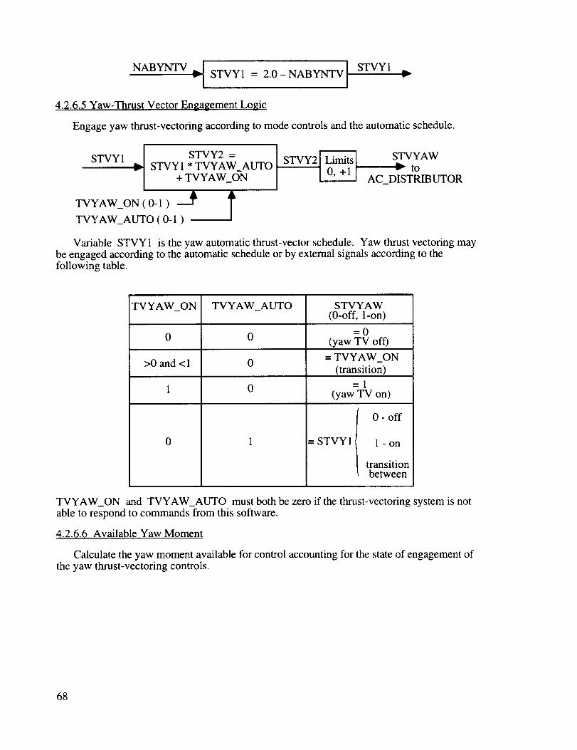
NABYNTV ,d STVY1 = 2.0 NABYNTV] STVY1Iw"- I -- I
4.2.6.5 Yaw-Thrust Vector Engagement Logic
Engage yaw thrust-vectoring according to mode controls and the automatic schedule.
I
STVY1 I STVY2 =
] STVY1 * TVYAW_AUTO+ TVYAW_ON
TVYAW_ON ( 0-1 )A
TVYAW_AUTO ( 0-1 )
STVYAWto
AC_DISTRIBUTOR
Variable STVY 1 is the yaw automatic thrust-vector schedule. Yaw thrust vectoring maybe engaged according to the automatic schedule or by external signals according to thefollowing table.
TVYAW_ON
0
>0 and < 1
1
TVYAW_AUTO STVYAW(0-off, 1-on)
=00 (yaw TV off)
0 = TVYAW_ON(transition)
0
0
=1(yaw TV on)
= STVYI_
I 0 - off
1 - on
transitiont between
TVYAW_ON and TVYAW_AUTO must both be zero if the thrust-vectoring system is notable to respond to commands from this software.
4.2.6.6 Available Yaw Moment
Calculate the yaw moment available for control accounting for the state of engagement ofthe yaw thrust-vectoring controls.
68

NAVAIL (ft-lb)NAERO(ft-lb) _)
NTV (ft-lb) _
tO
DX_INTERCONNECT
NTVS (ft-lb)
to v
DX_INTERCONNECT
STVYAW (0 to 1) from DX_YAWTV_ENGAGE
4.2.7 DX_ROLLTV_ENGAGE (USR51FJL) 40 Hz
This module manages the roll-moment producing controls and implements automatic yaw
thrust-vectoring logic.
1. Calculates roll-moment capabilities of primary aerodynamic and thrust-vectoringcontrols.
2. Calculates limited ratio of aerodynamic and thrust-vectoring roll moments.
3. Implements roll thrust-vectoring engagement logic.4. Implements automatic roll thrust-vectoring engage schedule.5. Calculates the roll-moment available from the combined aerodynamic and thrust-
vectoring controls.
4.2.7.1 Roll-Moment Capability of Aerodynamic Controls
Calculate the roll moment produced by the primary controls for one unit of roll Pseudo Control
(VROLL = 1.0).
QBAR, lb/ft 2 _,
FROLL ! LAEROfrom
DX_FROLL_FUNCTION
LAERO = 1048.0 * QBAR * FYAW
LAERO
"- (ft-lb)
4.2.7.2 Roll-Moment Capability of Thrust-Vectoring Controls
Calculate the roll moment produced by the thrust-vectoring controls for 15 degrees of rollthrust-vectoring.
THRUST _["_-_ ,,.._ LTV
(lb) ,.- _ v (ft-lb)
LTV = 0.40 * THRUST
69
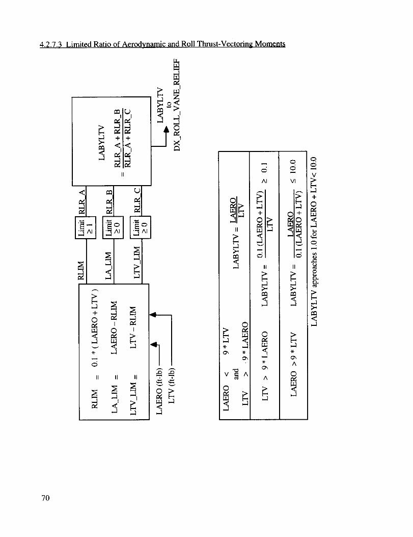
4.2.7.3 Limited Ratio of Aerodynamic and Roll Thrust-Vectoring Moments
+
in<.
>
I
O
II II II
I
-11-1
-1
mi
0 ;>
-1
_:_I_" -1I.T.JI_ +',_I
II
°-1
©
©
AI
II
O
-1
A
C_
C_
;>
-1A -t-
_0
.1
II
,-i
,-:1W
C_
C)
O
V>b-,-1
+
©
<-1
o
>
70

4.2.7.4 Roll Thrust-Vector Automatic Engagement Schedule
Calculate the automatic roll thrust-vectoring engagement schedule according to the ratio of
aerodynamic and thrust-vectoring roll moments.
LABYLTV _][ STVR1 = 2.0-LABYLTV[ STVR1
4.2.7.5 Roll Thrust-Vector Engagement Logic
Engage roll thrust-vectoring according to mode controls and the automatic schedule.
STVR2 =
STVR 1 STVR 1 * TVROLL_AUTO
+ TVROLL_ON
TVROLL_ON ( O-1 ) _ t
/TVROLL_AUTO ( O-1 )
STVROLL•.- to
AC_DISTRIBUTOR
Variable STVRI is the automatic roll thrust-vector schedule. Roll thrust vectoring may be
engaged according to the automatic schedule or by external signals according to the followingtable.
TVROLL_ON TVROLL_AUTO STVROLL(0-off, 1-on)
=00 0 (roll TV off)
>0 and < 1 0= TVROLL_ON
(transition)
=1(roll TV on)
0
0
= STVR 1
0 - off
/ l ontransitionbetween
TVROLL_ON and TVROLL_AUTO must both be zero if the thrust-vectoring system is not
able to respond to commands from this software.
71

4.2.7.6 Available Roll Moment
Calculate the roll moment available for control accounting for the state of engagement of the
thrust-vectoring controls.
LAERO (fl-lb) ._
LTV (ft-lb) LTVS (ft-lb)
STVROLL (0 to 1) from DX_ROLLTV_ENGAGE
LAVAIL (ft-lb)
to v
DX_INTERCONNECT
4.2.8 DX_INTERCONNECT (USR35FJL) 80 Hz
This module transforms stability-axis roll and yaw acceleration commands (VLAT_RPS2and VDIR_RPS2) calculated by the lateral/directional feedback control law into body-axis
moments and generates roll and yaw Pseudo Control variables (VROLL and VYAW).
4.2.8.1 Axis Transformation
Convert stability-axis commands VLAT_RPS2 and VDIR_RPS2 into body-axiscommands ROLL_ACCEL and YAW_ACCEL.
VLAT_RPS2 ( rad/sec 2 )
VDIR_RPS2 ( rad/sec 2 )
SIN_AOA
COS_AOA
lw'-_
AxisT
,,._ Tranformation_v
ROLL_ACCEL ( rad/sec 2 )L_
YAW_ACCEL ( rad/sec 2 )
w
ROLL_ACCEL = VLAT_RPS2 * COS_AOA - VDIR_RPS2 * SIN_AOAYAW_ACCEL = VLAT_RPS2 * SIN_AOA + VDIR_RPS2 * COS_AOA
4.2.8.2 Inertial Coupling
Calculate the control moments needed to compensate for roll and yaw accelerations forcoupled airplane rotations about pitch, roll, and yaw axes.
I PQ
P_DPS (deg/sec) ------_L_ XlS01I_J + L_ v
Q_DPS (deg/sec) ----_ _
R_DPS (deg/sec)
Inertial
Coupling
ROLL COUPLING i ft-lb t- _sl_ft2/
YAW COUPLING Ift-_-_- _sl_ft 2]
ROLL_COUPLING = P1 * PQ + P2 *RQYAW_COUPLING = P3 * PQ + P4 * RQ
72
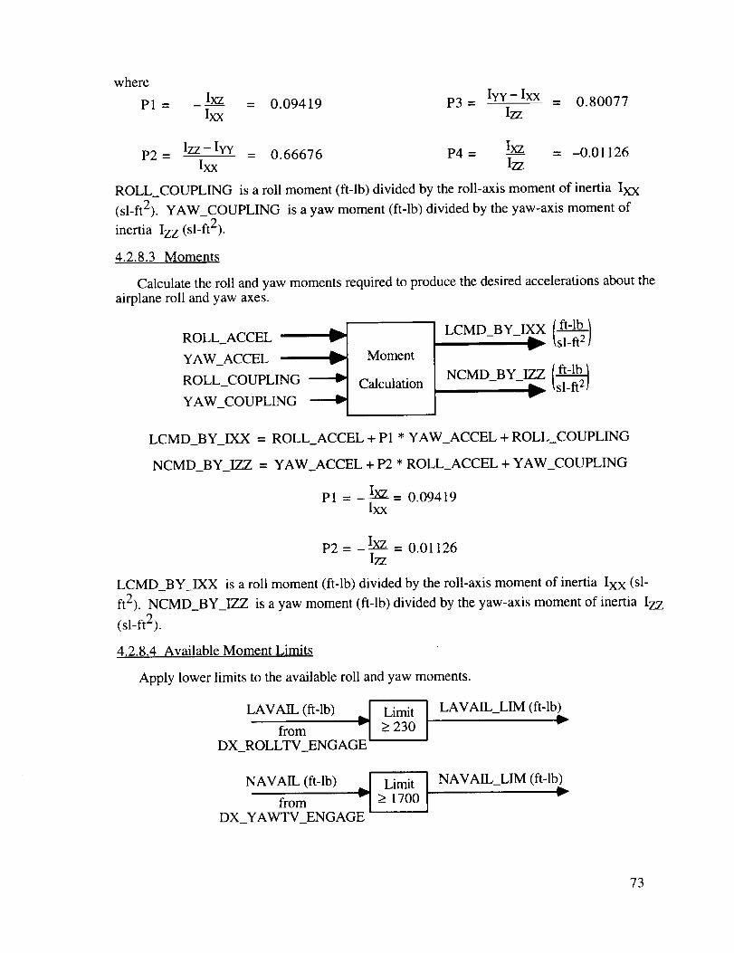
whereP1 = Ixz = 0.09419 P3- Iyy-Ixx
Ixx Izz- 0.80077
P2 = Izz-Ivy _ 0.66676 P4 = Ixz = -0.01126Ixx I77
ROLL_COUPLING is a roll moment (ft-lb) divided by the roll-axis moment of inertia Ixx
(sl-ft2). YAW_COUPLING is a yaw moment (ft-lb) divided by the yaw-axis moment of
inertia Izz (sl-ft2).
4.2.8.3 Moments
Calculate the roll and yaw moments required to produce the desired accelerations about the
airplane roll and yaw axes.
ROLL_ACCEL v
YAW_ACCEL
ROLL_COUPLING
YAW_COUPLING
Moment
Calculation
LCMD BY _X /ft-lb/_ _ _ _sl-fla/
NCMD BY _ [ft-__ _ _sl_ft21
LCMD_BY_IXX = ROLL_ACCEL + P1 * YAW_ACCEL + ROLL_COUPLING
NCMD_BY_IZZ = YAW_ACCEL + P2 * ROLL_ACCEL + YAW_COUPLING
P1 = _ I____= 0.09419Ixx
P2=-Ixz = 0.01126I77
LCMD_BY_IXX is a roll moment (ft-lb) divided by the roll-axis moment of inertia Ixx (si-
ft2). NCMD_BY_IZZ is a yaw moment (ft-lb) divided by the yaw-axis moment of inertia Izz
(sl-ft2).
4.2.8.4 Available Moment Limits
Apply lower limits to the available roll and yaw moments.
LAVAIL (ft-lb)
from " [DX_ROLLTV_ENGAGE"
Limit
> 230 LAVAIL_LIM (fl-lb)
NAVAIL (ft-lb) .q Limit ]from > 1700
DX_YAWTV_ENGAGE
NAVAIL_LIM (fl-lb)
73
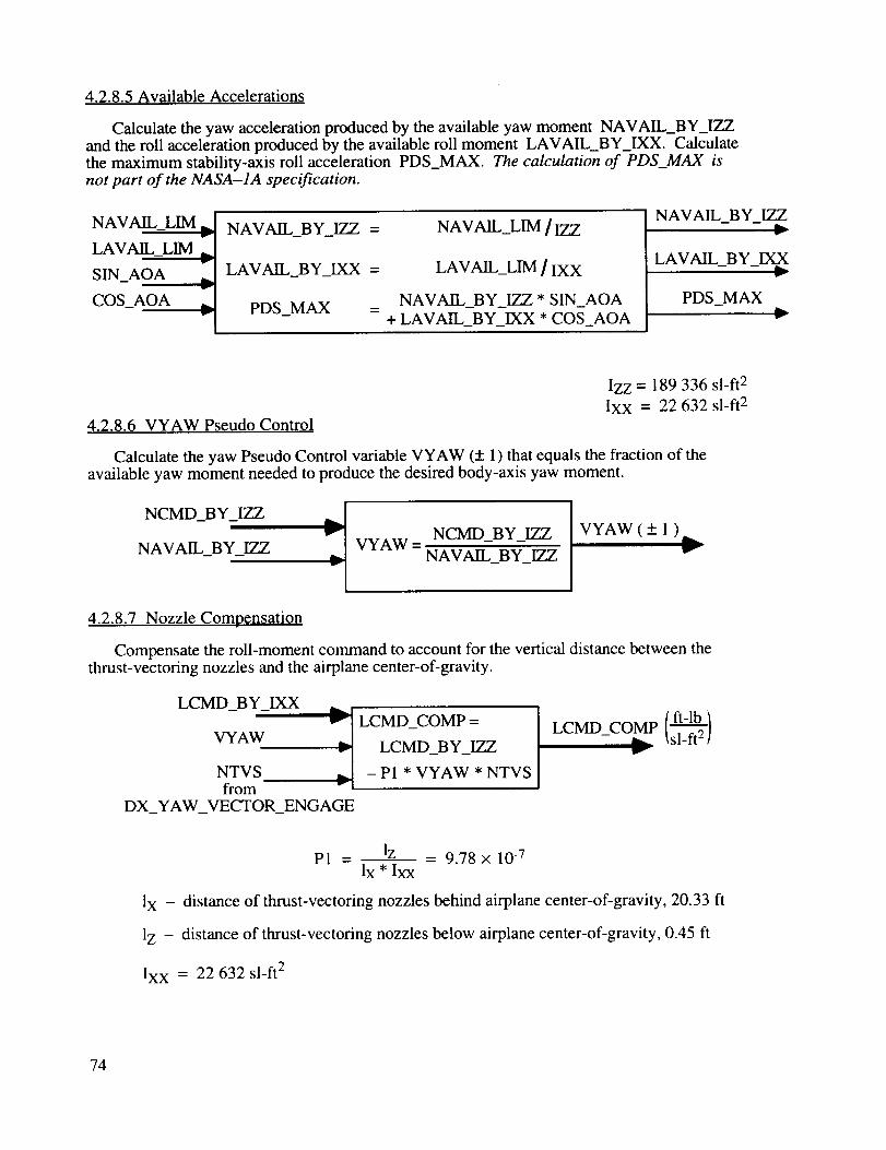
4.2.8.5 Available Accelerations
Calculate the yaw acceleration produced by the available yaw moment NAVAIL_BY_IZZand the roll acceleration produced by the available roll moment LAVAIL_BY_IXX. Calculatethe maximum stability-axis roll acceleration PDS_MAX. The calculation of PDS_MAX isnot part of the NASA-1A specification.
NAVA1L_LIM _.
LAVAIL_LIM ,._
SIN_AOA L
COS_AOA _.
NAVAIL_BY_IZZ = NAVAIL_LIM / IZZ
LAVAIL_BY_IXX = LAVAIL_LIM / IXX
PDS MAX NAVAIL_BY_IZZ * SIN_AOA- = + LAVAIL_BY_IXX * COS_AOA
NAVAIL_BY_IZZ
LAVAIL_BY_IXX
PDS_MAX
4.2.8.6 VYAW Pseudo Control
Izz = 189 336 sl-ft 2
Ixx = 22 632 sl-ft 2
Calculate the yaw Pseudo Control variable VYAW (+ 1) that equals the fraction of theavailable yaw moment needed to produce the desired body-axis yaw moment.
NCMD_BY_IZZ _[NAVAIL_BY_IZZ
-IVYAW = NCMD_BY_IZZ
NAVAIL_BY_IZZ
VYAW ( +_ 1 )
4.2.8.7 Nozzle Compensation
Compensate the roll-moment command to account for the vertical distance between thethrust-vectoring nozzles and the airplane center-of-gravity.
LCMD_BY_IXX
VYAW
NTVSfrom
v LCMD_COMP =
_'- LCMD_BY_IZZ
- P 1 * VYAW * NTVS
DX_YAW_VECTOR_ENGAGE
LCMD CO MP / ft-lb /- _sl-ft 2 /W
P1 - lz - 9.78 × 10 -7Ix * Ixx
lX - distance of thrust-vectoring nozzles behind airplane center-of-gravity, 20.33 fl
1Z - distance of thrust-vectoring nozzles below airplane center-of-gravity, 0.45 fl
Ixx = 22 632 sl-ft 2
74

4.2.8.8 VROLL Pseudo Control
Calculate the roll Pseudo Control VROLL (+ 1) that equals the fraction of the available roll
moment needed to produce the desired body-axis roll moment.
LCMD_COMP
LAVAIL_BY_IXX _JVROLL = LCMD_COMPLAVAIL_BY_IXX
-IVROLL ( + 1 ),._
4.2.9 AC_DISTRIBUTOR (USR38FJL) 80 Hz
This module distributes the roll and yaw Pseudo Control variables (VROLL and VYAW)
among the primary aerodynamic controls (ailerons, rudders, and differential stabilator) and theroll and yaw thrust-vectoring controls. This module employsDX_YAW_VANE_RELIEF(USR54FJL) and DX_ROLL_VANE_RELIEF(USR53FJL) to
alleviate long-term commands to the thrust-vectoring system.
4.2.9.1 Yaw Thrust-Vector Pseudo Control
Calculate the yaw thrust-vector Pseudo Control TVYAW_NOM equal to the product ofthe yaw Pseudo Control variable VYAW and the yaw thrust-vectoring engagement signalSTVYAW.
VYAWfrom
DX_INTERCONNECT
STVYAWfrom
DX_YAW_VECTOR_ENGAGE
TVYAW NOM ( + 1 )
h._ _ -to
_ AW_VANE_RELIEF
4.2.9.2 Roll Thrust-Vector Pseudo Control
Calculate the roll thrust-vector Pseudo Control TVROLL_NOM equal to the product of theroll Pseudo Control variable VROLL and the yaw thrust-vectoring engagement signalSTVROLL.
VROLLfrom
DX_INTERCONNECT
TVROLL NOM ( + 1 )
-to
m DX_ROLL VANE RELIEF
!STVROLLfrom
DX_ROLL_VECTOR_ENGAGE
4.2.9.3 Vane Relief
Execute vane-relief modules depending on multirate clock state.
75
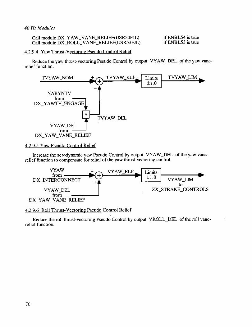
40 Hz Modules
Call module DX_YAW_VANE_RELIEF(USR54FJL)Call module DX_ROLL_VANE_RELIEF(USR53FJL)
4.2.9.4 Yaw Thrust-Vectoring Pseudo Control Relief
if ENBL54 is trueif ENBL53 is true
Reduce the yaw thrust-vectoring Pseudo Control by output VYAW_DEL of the yaw vane-relief function.
TVYAW NOM TVYAW_RLF.._ [ Limits
- "l _+,0
NABYNTV - lfrom
DX_YAWTV_ENGAGE
EVYAW_DF_L
from
_----JTVYAW_DEL
DX_YAW_VANE_RELIEF
TVYAW_LIM _._Imv
4.2.9.5 Yaw Pseudo Control Relief
Increase the aerodynamic yaw Pseudo Control by output VYAW_DEL of the yaw vane-relief function to compensate for relief of the yaw thrust-vectoring control.
VYAW _+ VYAW_RLF .._! Limits ]® I "from v v +1.0 IDX_INTERCONNECT I VYAW_LIM
+ l toVYAW_DEL ZX_STRAKE_CONTROLSfrom
DX_YAW_VANE_RELIEF
4.2.9.6 Roll Thrust-Vectoring Pseudo Control Relief
Reduce the roll thrust-vectoring Pseudo Control by output VROLL_DEL of the roll vane-relief function.
76

TVROLL_NOM
LABYLTVfrom
DX_ROLLTV_ENGAGE
TVROLL_LIM
TVROLL_DELVROLL_DEL
fromDX_ROLL_VANE_RELIEF
4.2.9.7 Roll Pseudo Control Relief
Increase the aerodynamic roll Pseudo Control by output VROLL_DEL of the roll vane-
relief function to compensate for relief of the roll thrust-vectoring control.
VROLLfrom v_+_ VROLL_RLF v_ 111Limits+_1.0 I VROLL LIM _
DX_INTERCONNECT + _
/VROLL_DELfrom
DX_ROLL_VANE_RELIEF
4.2.9.8 Distribution of Pseudo Controls
Distribute the aerodynamic Pseudo Controls to the aerodynamic control surfaces and thethrust-vectoring Pseudo Controls to the thrust-vectoring commands.
Ailerons
VROLL_LIM ..._
VYAW_LIMIn,,,"-
DA_VROLLt I_
DA_YVAW_ liD'-
DA_DEG =
DA_VROLL * VROLL_LIM
+ DA_VYAW * VYAW_LIM
DA_DEG
tfrom DX_DISTRIBUTOR_GAINS
One degree of DA_DEG commands one degree TED motion of the left aileron and onedegree TEU motion of the right aileron to produce a right-wing-down roll moment.
77
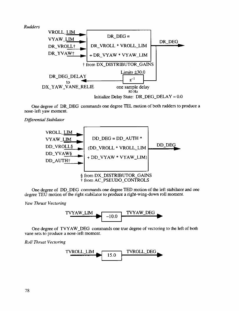
Rudders
VROLL LIM
VYAW_LIM ..__
DR_VROLL_-
DR_YVAWt
DR_DEG =
DR_VROLL * VROLL_LIM
+ DR_VYAW * VYAW_LIM
t from DX_DISTRIBUTOR_GAINS
Limits +_30.0
DR_DEG_DELAY I z-' tto -'"
DX_YAW_VANE_RELIE one sample delay80 Hz
DR_DEG
Initialize Delay State: DR_DEG_DELAY = 0.0
One degree of DR_DEG commands one degree TEL motion of both rudders to produce anose-left yaw moment.
Differential Stabilator
VROLL_LIM ,..._r
VYAW_LIM ,._r
DD_VROLL§ ;_.
DD_YVAW§ _,.
DD_AUTH_ D,-
DD_DEG = DD_AUTH *
(DD_VROLL * VROLL_LIM
+ DD_VYAW * VYAW_LIM)
DD_DEG
§ from DX_DISTRIBUTOR_GAINSt from AC_PSEUDO_CONTROLS
One degree of DD_DEG commands one degree TED motion of the left stabilator and one
degree TEU motion of the right stabilator to produce a right-wing-down roll moment.
Yaw Thrust Vectoring
TVYAW_LIM _'I -10.0 TVYAW_DEG w-"_
One degree of TVYAW_DEG commands one true degree of vectoring to the left of bothvane sets to produce a nose-left moment.
Roll Thrust Vectoring
I ] TVROLL DEG m._TVROLL_LIM _ 15.0 - w-
78

Onedegreeof TVROLL_DEGcommandsone true degree of vectoring of the left vane setdownward and one true degree of vectoring of the right vane set upward to produce a right-
wing-down moment.
4.2.9.9 Accelerometer Correction
Calculate the interference of yaw thrust-vectoring commands on the lateral accelerometer
output. This function is not part of the NASA-1A specification.
TVYAW_LIM _jNTVS from DX_YAWTV_ENGAGE
"-I
TV_CORR_G = 7.0 x 10⁻⁷
x NTVS × TVYAW_LIM
TV_CORR_G
4.2.10 DX_YAW VANE RELIEF(USR54FJL) 40 Hz
The yaw vane-relief function is included in the Pseudo Controls system to reduce long-termdeflections of the thrust-vectoring system by substituting equivalent deflections of the
aerodynamic controls (commanded through VYAW) whenever possible. As a result ofsimulation tests, a delayed value of the commanded rudder position is used to limit the yawvane relief function if it should interfere with coordination of the rudder with the other controls
when rudder is used in the generation of coordinated roll moments (commanded throughVROLL).
Timing of the relief action is provided by a nonlinear low-pass filter. The filter functionslike a unity-gain filter with a 1.25 second time constant while it is substituting aerodynamiccontrols for yaw thrust-vectoring control. When yaw commands are decreasing, theaerodynamic and thrust-vectoring controls conflict in that they oppose each other. A conflictdetector causes the loop gain of the filter to increase to a fast (0.125 second) time constant to
quickly reduce the relief action.
4.2.10.1 VYAW Required
Calculate the amount VYAW needs to be increased to alleviate TVYAW without
exceeding VYAW = +1.0.
VYAWfrom
DX_INTERCONNECT
TVYAW_NOMfrom
AC_DISTRIBUTOR
Lv
NABYNTVfrom _v
DX_YAW_VECTOR_ENGAGE
VYAW ..]from
DX_INTERCONNECT "1
VYAW_REQD =
VYAW + TVYAW_NOM
NABYNTV
Limit]+_ 1.0
VYAW_NOM_LIM
VYAW_REQD
IL 'I+_ 1.0
+ _VYAW_REQD_LIM
- DEL_VYAW
79

4.2.10.2 Positive Limit
Calculate the amount DEL_VYAW exceeds the rudder capability for positive VYAW.
DR DEG DELAY [DR DEG DELAY- from ------_ - -
AC_DISTRmUTORI 30.0
DEL_VYAW
+ 1.0 [ POS_VYAW_AVAIL
ULIM_VYAW_RLF Limits ]
00, +1.0I| Lower VYAW RLF GT ULIMVYAW_RLF_OVER ,_ Limit - - -
[ at0.0
A change of VYAW of one unit causes a change of the rudder command of-30 degrees. This function calculates the amount of VYAW that is available for positivechanges (POS_VYAW_AVAIL) based on the previous rudder position command(DR_DEG_DELAY). This is compares with change of VYAW calculated above(DEL_VYAW) to yield the amount that DEL_VYAW exceeds the amount that would drive therudder into saturation (VYAW_RLF_GT_ULIM).
4.2.10.3 Negative Limit
Calculate the amount DEL_VYAW exceeds the rudder capability for negative VYAW.
DR DEG DELAY I DR DEG DELAY- from _ - -
AC_DISTRIBUTOR I 30.0
DEL_VYAW
1.0 NEG_VYAW_AVAIL
LLIM_VYAW_RLF I Limits I
+-+ R__I lil'0'0"0
VYAW_RLF_UNDE Upper VYAW RLF LT LLIMLimitat 0.0
This function is the similar to the positive limit except that it is based on negative changesof VYAW.
4.2.10.4 Yaw-Relief Authority
Calculate the amount VYAW can be changed in relieving TVYAW without exceedingrudder deflection limits. The authority of the yaw vane relief function is further limited tobeing able to change VYAW by 0.50 (50 percent authority).
DEL_VYAW
VYAW_RLF_GT_ULIM
VYAW_RLF LT LLIM
DEL_V Y AW_LIM _ Y A W_RL F_ A UTH
-1_+O5Ol.
80

4.2.10.5 Yaw-Relief Dynamics - Nonlinear Low-Pass Filter
i
<
!,_t
<
I
<
<
<
m
t",d
.'_ _
i
I
o
o
o_
81
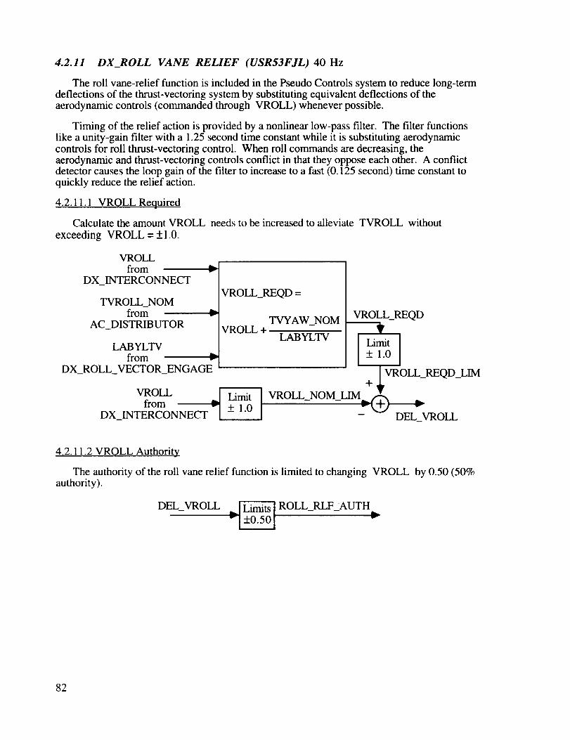
4.2.11 DX_ROLL VANE RELIEF (USR53FJL) 40 Hz
The roll vane-relief function is included in the Pseudo Controls system to reduce long-termdeflections of the thrust-vectoring system by substituting equivalent deflections of theaerodynamic controls (commanded through VROLL) whenever possible.
Timing of the relief action is provided by a nonlinear low-pass filter. The filter functionslike a unity-gain filter with a 1.25 second time constant while it is substituting aerodynamic
controls for roll thrust-vectoring control. When roll commands are decreasing, theaerodynamic and thrust-vectoring controls conflict in that they oppose each other. A conflictdetector causes the loop gain of the filter to increase to a fast (0.125 second) time constant toquickly reduce the relief action.
4.2.11.1 VROLL Required
Calculate the amount VROLL needs to be increased to alleviate TVROLL without
exceeding VROLL = +1.0.
VROLLfrom
DX_INTERCONNECT
TVROLL_NOMfrom
AC_DISTRIBUTOR
a_v
lb.v
LABYLTVfrom v'_
DX_ROLL_VECTOR_ENGAGE
VROLL_REQD=
VROLL+
VROLL _ Limitfrom + 1.0DX_INTERCONNECT -
TVYAW_NOM
LABYLTV
VROLL_REQD
I Limit I+ 1.0
+ _VROLL_REQD_LIM
] VROLL NOM LIM
- DEL_VROLL
4.2.11.2 VROLL Authority
The authority of the roll vane relief function is limited to changing VROLL by 0.50 (50%authority).
DEL_VROLL ROLL_RLFzAUTH-1+o.5ol ,--
82

4.2.11.3 Roll-Relief Dynamics - Nonlinear Low-Pass Filter
<
©
..1t
.1©
m
r_ ii
oooo
...._
L.
¢-o
©
e-. ,,..._
_5
83
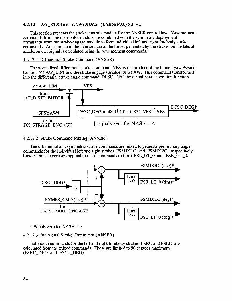
4.2.12 DX_STRAKE CONTROLS (USR58FJL) 80 Hz
This section presents the strake controls module for the ANSER control law. Yaw momentcommands from the distributor module are combined with the symmetric deploymentcommands from the strake-engage module to form individual left and right forebody strakecommands. An estimate of the interference of the forces generated by the strakes on the lateralaccelerometer signal is calculated using the yaw moment commands.
4.2.12.1 Differential Strak¢ Command (ANSER)
The normalized differential strake command VFS is the product of the limited yaw PseudoControl VYAW_LIM and the strake engage variable SFSYAW. This command transformedinto the differential strake angle command DFSC_DEG by a nonlinear calibration function.
VYAW_LIM
from _ E
AC_DISTRIBUTOR
SFSYAWt
from
DX_STRAKE_ENGAGE
DFSC_DEG = -48.0 ( 1.0 + 0.875 VFS 2 ) VFS
t Equals zero for NASA-1A
DFSC DEGtt
4.2.12.2 Strake Command Mixing (ANSER)
The differential and symmetric strake commands are mixed to generate preliminary anglecommands for the individual left and right strakes FSMIXLC and FSMIXRC, respectively.Lower limits at zero are applied to these commands to form FSL_GT_0 and FSR_GT_0.
+ FSMIXRC (deg)*
DFSC_DEG* FSR_LT_0 (deg)*
SYMFS_CMD (deg)*
from
DX_STRAKE_ENGAGE
* Equals zero for NASA-1A
4.2.12.3 Individual Strake Commands (ANSER)
FSMIXLC (deg)*
FSL_LT_0 (deg)*
Individual commands for the left and right forebody strakes FSRC and FSLC arecalculated from the mixed commands. These are limited to 90 degrees maximum(FSRC_DEG and FSLC_DEG).
84

FSMIXRC (deg)*
FSR LT 0 (deg)*
I - ___+ FSRC (deg)* _ FSRC_DEG (deg)_
FSL_L_ _
FSMIXLC (del)*
* Equals zero for NASA-1A
4.2.12.4 Accelerometer Correction (ANSER)
Calculate the interference of differential forebody strake deflections on the lateralaccelerometer output.
VYAW_LIM ( + 1 ) from DX_DISTRIBUTOR
AOA DEG _
( g's / ft-lb )
NFSS ( ft-lb )t from DX_STRAKE_ENGAGE
FS_CORR_G ( g's )t,..._
* Equals zero for NASA-1A
AOA_DEG FSCSCH
20.0 4.2 x 10⁶
36.0 4.2 x 10⁻⁶
50.0 3.0 x 10⁻⁶
75.0 3.0 x 10⁻⁶
4.2.13 Common Storage
Variables used to communicate data among the modules are placed in a common storageblock in the LaRC implementation. These variables are listed in the following table. The table
presents: 1) the location of the data in the common block; 2) the FORTRAN name of the datavariable; 3) the variable identification and units; 4) the module numbers where the variablevalues are calculated; and 5) the module(s) where the data is used. This common block doesnot include variables that are defined and used entirely within a given module.
85
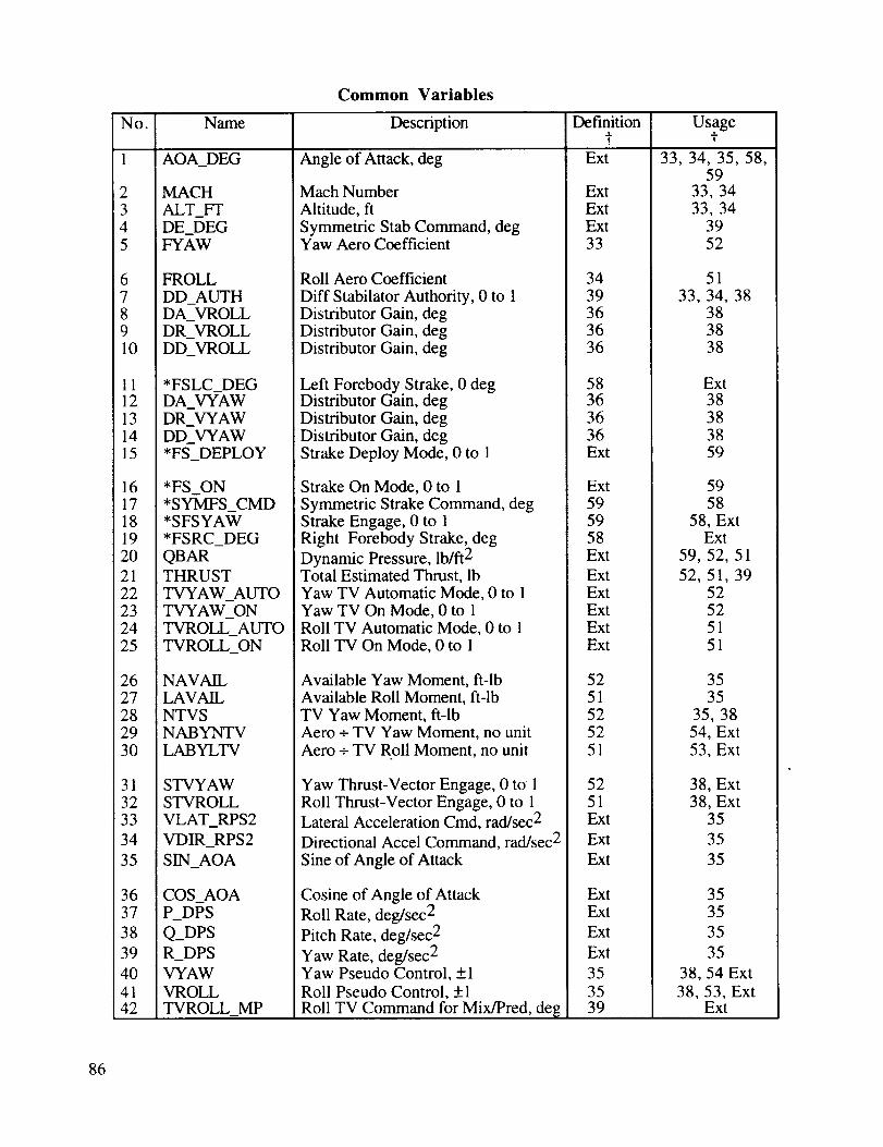
Common Variables
Name Description Definition Usaget t
AOA_DEG Angle of Attack, deg Ext
No.
2 MACH
3 ALT_FT4 DE_DEG5 FYAW
6 FROLL
7 DD_AUTH8 DA_VROLL9 DR_VROLL10 DD_VROLL
11 *FSLC DEG12 DA_ AW13 DR_VYAW14 DD_VYAW15 *FS_DEPLOY
16 * FS_ON17 *SYMFS_CMD18 *SFSYAW19 *FSRC_DEG
20 QBAR21 THRUST
22 TVYAW_AUTO23 TVYAW_ON
24 TVROLL_AUTO
25 TVROLL_ON
26 NAVAIL27 LAVAIL
28 NTVS29 NABYNTV30 LABYLTV
31 STVYAW32 STVROLL
33 VLAT_RPS2
34 VDIR_RPS2
35 SIN_AOA
36 COS_AOA37 P_DPS
38 Q_DPS39 R DPS
40 V'YAW
41 VROLL42 TVROLL_MP
Mach Number
Altitude, ft
Symmetric Stab Command, degYaw Aero Coefficient
Roll Aero Coefficient
Diff Stabilator Authority, 0 to 1Distributor Gain, degDistributor Gain, degDistributor Gain, deg
Left Forebody Strake, 0 degDistributor Gain, degDistributor Gain, degDistributor Gain, degStrake Deploy Mode, 0 to 1
Strake On Mode, 0 to 1
Symmetric Strake Command, degStrake Engage, 0 to 1Right Forebody Strake, deg
Dynamic Pressure, lb/ft 2Total Estimated Thrust, lbYaw TV Automatic Mode, 0 to 1Yaw TV On Mode, 0 to 1Roll TV Automatic Mode, 0 to 1Roll TV On Mode, 0 to 1
Available Yaw Moment, fi-lbAvailable Roll Moment, fl-lbTV Yaw Moment, ft-lbAero - TV Yaw Moment, no unitAero - TV Roll Moment, no unit
Yaw Thrust-Vector Engage, 0 to 1Roll Thrust-Vector Engage, 0 to 1Lateral Acceleration Cmd, rad/sec 2
Directional Accel Command, rad/sec 2
Sine of Angle of Attack
Cosine of Angle of Attack
Roll Rate, deg/sec 2
Pitch Rate, deg/sec 2
Yaw Rate, deg/sec 2Yaw Pseudo Control, +1
Roll Pseudo Control, +1
Roll TV Command for Mix/Pred, de[[
ExtExtExt33
3439363636
58363636Ext
Ext595958Ext
ExtExtExtExtExt
5251525251
5251Ext
Ext
Ext
ExtExt
Ext
Ext
35
3539
33, 34, 35, 58,59
33, 34
33, 343952
51
33, 34, 38383838
Ext38383859
5958
58, ExtExt
59, 52, 51
52, 51, 3952525151
3535
35, 3854, Ext53, Ext
38, Ext38, Ext
35
35
35
3535
35
35
38, 54 Ext
38, 53, ExtExt
86
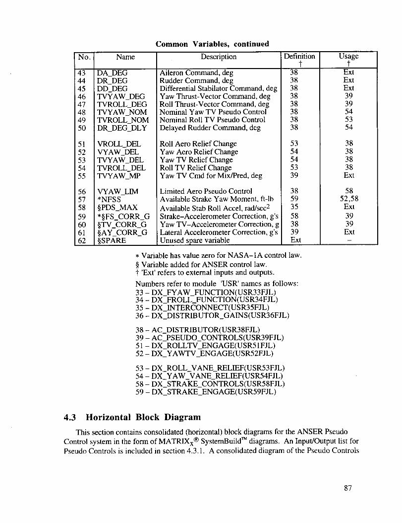
Common Variables, continued
No. Name
43 DA_DEG44 DR_DEG45 DD_DEG46 TVYAW_DEG47 TVROLL_DEG48 TVYAW_NOM49 TVROLL_NOM50 DR_DEG_DLY
51 VROLL_DEL52 VYAW_DEL53 TVYAW_DEL54 TVROLL_DEL55 TVYAW_MP
56 VYAW_LIM57 *NFSS
58 §PDS_MAX
59 *§FS_CORR_G60 §TV_CORR_G61 §AY_CORR_G62 §SPARE
Description
Aileron Command, degRudder Command, degDifferential Stabilator Command, degYaw Thrust-Vector Command, degRoll Thrust-Vector Command, degNominal Yaw TV Pseudo ControlNominal Roll TV Pseudo Control
Delayed Rudder Command, deg
Roll Aero Relief ChangeYaw Aero Relief ChangeYaw TV Relief ChangeRoll TV Relief ChangeYaw TV Cmd for Mix/Pred, deg
Limited Aero Pseudo Control
Available Strake Yaw Moment, ft-lb
Available Stab Roll Accel, rad/sec 2
Strake-Accelerometer Correction, g'sYaw TV-Accelerometer Correction, gLateral Accelerometer Correction, g's
Unused spare variable
Definitiont
3838383838383838
5354545339
385935
583839Ext
Usage
ExtExtExt3939545354
38383838Ext
58
52,58Ext
3939Ext
• Variable has value zero for NASA-1A control law.
§ Variable added for ANSER control law.
t 'Ext' refers to external inputs and outputs.
Numbers refer to module 'USR' names as follows:
33 - DX_FYAW_FUNCTION(USR33FJL)34 - DX_FROLL_FUNCTION(USR34FJL)35 - DX_INTERCONNECT(USR35FJL)36 - DX_DISTRIBUTOR_GAINS(USR36FJL)
38 - AC_DISTRIBUTOR(USR38FJL)39 - AC_PSEUDO_CONTROLS(USR39FJL)51 - DX_ROLLTV_ENGAGE(USR51FJL)
52 - DX_YAWTV_ENGAGE(USR52FJL)
53 - DX_ROLL_VANE_RELIEF(USR53FJL)54 - DX_YAW_VANE_RELIEF(USR54FJL)58 - DX_STRAKE_CONTROLS(USR58FJL)59 - DX_STRAKE_ENGAGE(USR59FJL)
4.3 Horizontal Block Diagram
This section contains consolidated (horizontal) block diagrams for the ANSER Pseudo
Control system in the form of MATRIXx® SystemBuild TM diagrams. An Input/Output list for
Pseudo Controls is included in section 4.3.1. A consolidated diagram of the Pseudo Controls
87

modules is shown in figures 4.4 (a) through 4.4 (c). A consolidated diagram of the ANSERcontrols module is shown in figure 4.5.
4.3.1 Input - Output Lists
Externals:
DX_FYAW_FUNCTIONDX_FROLL_FUNCTIONDX DISTRIBUTOR_GAINSDX_STRAKE_ENGAGEDX_YAWTV_ENGAGEDX_ROLLTV_ENGAGEDX_INTERCONNECT
AC_DISTRIBUTORDX_YAW_VANE_RELIEFDX_ROLL_VANE_RELIEFDX_STRAKE_CONTROLS
Inputs:
1
2
3
4
5
vlat_rps2
vdir_rps2
AOA_deg
p_dps
q_dps
USR33FJLUSR34FJLUSR36FJLUSR59FJLUSR52FJLUSR51FJLUSR35FJLUSR38FJLUSR54FJLUSR53FJLUSR58FJL
1 state variable1 state variable1 state variable
Instantaneous roll acceleration command
Instantaneous yaw acceleration command
Angle of attack (for scheduling)
Body-axis roll rate (for inertial decoupling)
Body-axis pitch rate (for inertialdecoupling)
rad/sec 2
rad/sec 2
degrees
deg/sec
deg/sec
r_dps
qbar
Body-axis yaw rate (for inertial decoupling) deg/sec
Dynamic Pressure (for determination of lb/ft 2aerodynamic control moments)
Thrust Total thrust both engines (for determination lbsof thrust-vectoring moments)
9
10
11
12
13
14
15
spare
Mach
alt_ft
Sin_AOA
Cos_AOA
de_deg
TVyaw_auto
unused input
Mach number (for scheduling)
Altitude (for scheduling)
Sine of AOA (for axis transformation)
Cosine of AOA (for axis transformation)
Symmetric Stabilator (elevator) command
Enable automatic operation of yaw thrust-vectoring engagement algorithm.
feet
degrees (+10.5TED, -24.0 TEU)
88
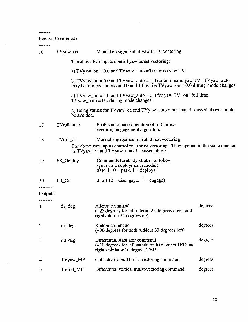
Inputs: (Continued)
16 TVyaw_on Manual engagement of yaw thrust vectoring
The above two inputs control yaw thrust vectoring:
a) TVyaw_on = 0.0 and TVyaw_auto =0.0 for no yaw TV
b) TVyaw_on = 0.0 and TVyaw_auto = 1.0 for automatic yaw TV. TVyaw_automay be 'ramped' between 0.0 and 1.0 while TVyaw_on = 0.0 during mode changes.
c) TVyaw_on = 1.0 and TVyaw_auto = 0.0 for yaw TV "on" full time.
TVyaw_auto = 0.0 during mode changes.
d) Using values for TVyaw_on and TVyaw_auto other than discussed above shouldbe avoided.
17 TVroll_auto Enable automatic operation of roll thrust-vectoring engagement algorithm.
18 TVroll_on Manual engagement of roll thrust vectoring
The above two inputs control roll thrust vectoring. They operate in the same manneras TVyaw_on and TVyaw_auto discussed above.
19 FS_Deploy Commands forebody strakes to followsymmetric deployment schedule(0 to 1:0 = park, 1 = deploy)
20
Outputs:
1
FS_On
da_deg
0 to 1 (0 = disengage, 1 = engage)
Aileron command
(+25 degrees for left aileron 25 degrees down andright aileron 25 degrees up)
degrees
2 dr_deg Rudder command
(+30 degrees for both rudders 30 degrees left)
degrees
3 dd_deg Differential stabilator command
(+10 degrees for left stabilator 10 degrees TED andright stabilator l0 degrees TEU)
degrees
4 TVyaw_MP Collective lateral thrust-vectoring command degrees
5 TVrolI_MP Differential vertical thrust-vectoring command degrees
89

Outputs:(Continued)
6 vroll
7 vyaw
8 NAbyNTV
9 STVyaw
10 LAbyLTV
11 STVroll
Roll PseudoControlvariable(body-axisrollmoment),+/- 1
Yaw PseudoControlvariable(body-axisyawmoment),+/- 1
Ratioof availableaerodynamicandthrust-vectoringyawcontrolmoments(limitedfor division)
Yaw thrustvectoringengagementvariable;0=off, l=on
Ratioof availableaerodynamicandthrust-vectoringroll controlmoments(limitedfor division)
Roll thrustvectoringengagementvariable;0=off, l=on
12 FSRC_deg Right forebodystrakecommand degrees
13 FSLC_deg Left forebodystrakecommand degrees
14 ay_corr_g Calculatedinterferencein lateralaccelerometer g'soutput
Thisquantitymaybesubtractedfrom thelateralaccelerometeroutputto correctfor directpick-upofforcesfrom theforebodystrakeandyaw thrust-vectoringcontrols.
15 pds_max Calculatedvalueof theavailablestability-axisroll rad/sec2acceleration
16 SFSyaw Forebodystrakeengagementvariable;0=off, 1=on
4.2
References
Lallman, Frederick J.: Relative Control Effectiveness Technique With Application to
Airplane Control Coordination. NASA TP 2416, Apr. 1985.
Lallman, Frederick J.: Preliminary Design Study of a Lateral-Directional Control SystemUsing Thrust Vectoring. NASA TM 86425, Nov. 1985.
9O
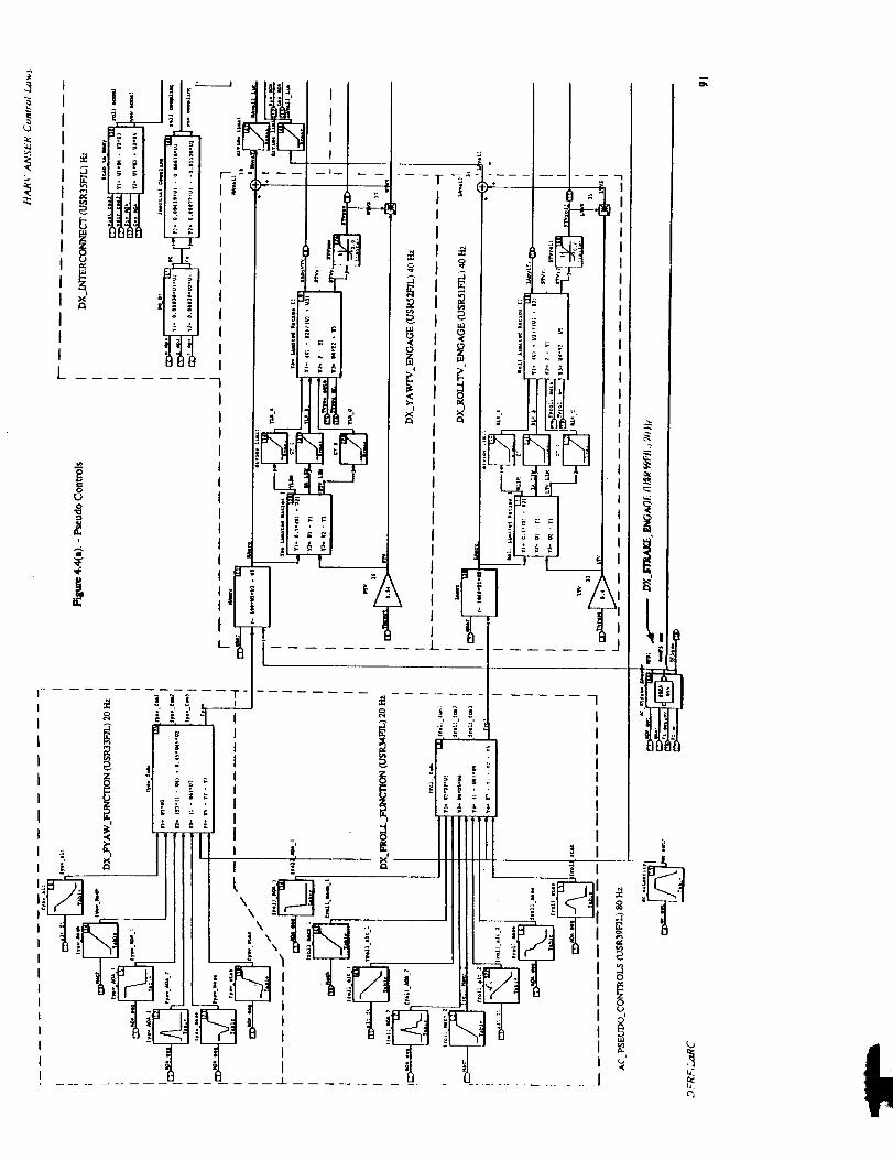
L_
,(
L
ii |
i 'I..... 7
" I
IIIli
__ f II
I
IIIIIIII
: ;I
.... XJ
0
0L)
1
IL
1_i!
!!
t_
r5

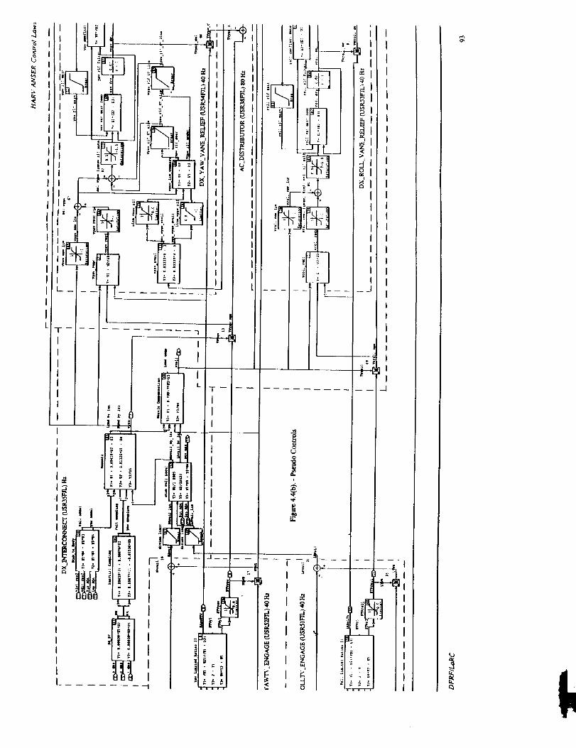
I
I
I
[
I
I
_ o
i- m
--- w _
_°_
II1_,
I
Ol
IIIIIII
II
__1
I
I-- -- .-.]
H
-1I
JlIII
IIIIII

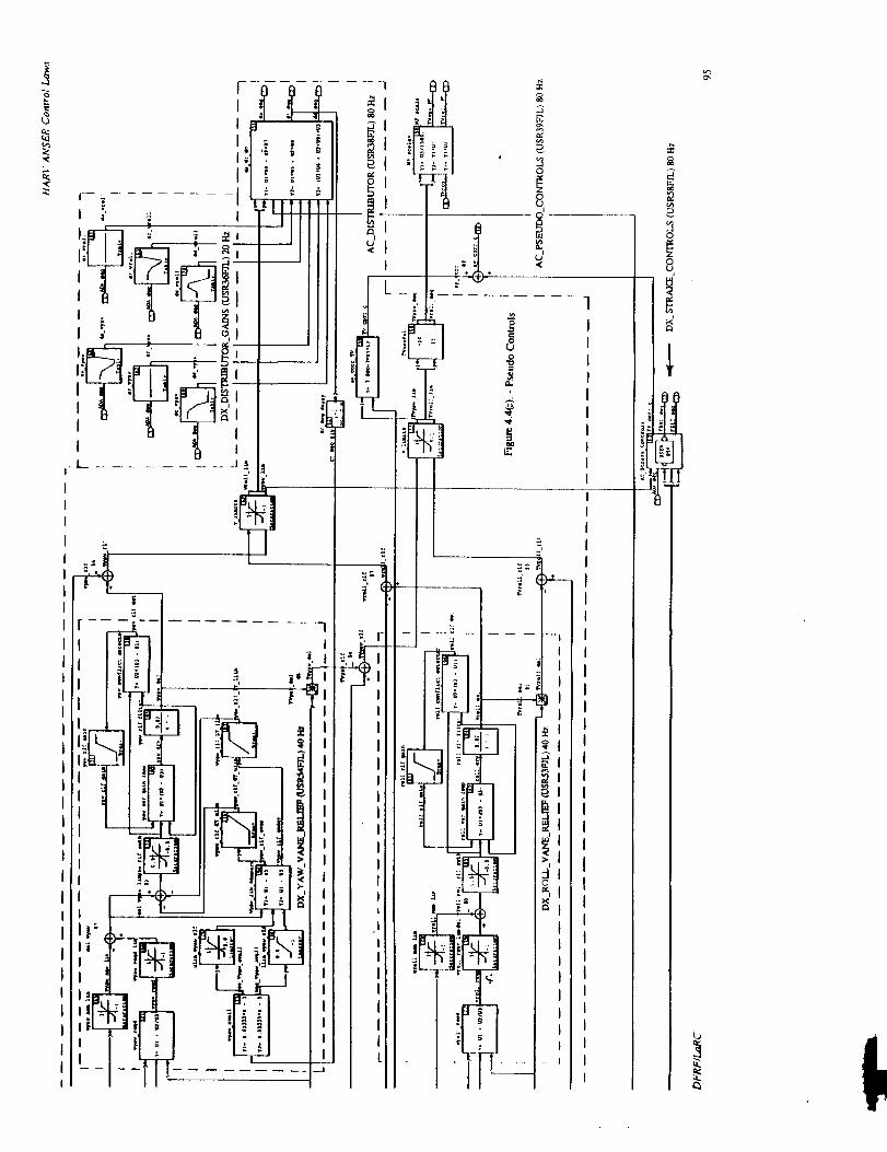
..I
If:
ij
m
i
I titI n
|
I
<.
!i °0
i+ °!i 'L,I
L !'" " <
H
]
E
7' l_-n
!,._ _l
_-- :'_g_-II /_, I
_l /:1
ii
0
oU
Ij
m.

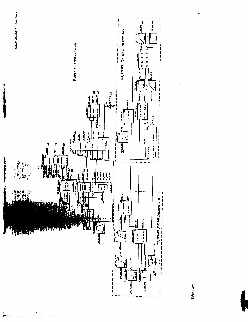
_e
*
,4
I
I
f_
I
,!IIIIIII!
c_


5.1 General
Chapter 5Interface
The purpose of this chapter is to define the interface between the HARV ANSER ControlLaws and the "outside world". Inputs include pilot stick and pedal commands, OBEScommands, measurements, calculated parameters, and discretes to turn "ON"/"OFF" variouscontrol law functions. Table 5.1 lists the inputs for the Longitudinal and Lateral/DirectionalANSER Control Laws only. The Mixer/Predictor I/O has not been included in the HARVANSER Control Law Specification. The requested outputs from the F- 18/HARVinstrumentation are defined in Table 5.2. These instrumentation parameters include deflectioncommands to the aerodynamic surfaces, thrust-vectoring commands to the Mixer/Predictor,
and internal variables brought out for diagnostic purposes only. Units are included in the inputand instrumentation tables. The variable names for the input and instrumentation tables agreewith the corresponding variable names in the FORTRAN code. The calculated inputs alongwith certain required accuracies are contained in section 5.3.
5.2 Input and Instrumentation Lists
TABLE 5.1 .- INPUTS.
NO
9
10
11
12
13
14
15
AUTO CODE DEFINITION UNITSSYMBOL
PSTICK Pitch stick in
LATST_IN Lateral Stick (-3 to +3) in
RUDPED_LBS Rudder Pedal (-100 to + 100) lbs
PTRIM Pitch trim in
YTRIM Yaw trim (- 1 to + 1) n.d.
RTRIM Roll trim (- 1 to + l) n.d.
PS_DPS Sensed body-axis roll rate deg/secP_DPS
Q Sensed body-axis pitch rate deg/secQS_DPSQ_DPS
RSDPS Sensed body-axis yaw rate deg/secR_DPS
NZ Normal acceleration - positive along z-axis gNZ_G
SINPHI Sine of INS roll angle n.d.
COSPHI Cosine of INS roll angle n.d.
SINTHE Sine of INS pitch angle n.d.SINTHETA
COSTHE Cosine of INS pitch angle n.d.COSTHETA
NY_G Sensed lateral acceleration g
99

TABLE 5.1.- INPUTS(Concluded).NO
16
17181920
21
22232425
26272829
30
313233343536
37
38
39
404142
43
AUTOCODE DEFINITION UNITSSYMBOL
VT Trueairspeed ft/secVTRUE_FPSMACH Machnumber n.d.AOAP Angle-of-attackPROBE degAOAINS Angle-of-attackINS degBDOT_INERT_ Sidesliprateinertial deg/secDPSH_FT Altitude (abovesealevel) ftALT_FTPS Staticpressure lb/ft2QBAR Dynamicpressure lb/ft2QCFILTER1 2.5rad/secfilteredimpactpressure lb/ft2QCFILTER2 10rad/secfilteredimpactpressure lb/ft2QCFILTER2_PSFRI Pressureratio - (QCFILTER2/PS) n.d.FGTOTL_LBS Left enginethrust lbsFGTOTR_LBS Rightenginethrust lbsDELSTM Stabilator,andpitchjet commandedposition deg
for trimTRMMING Trim flag (real)- n.d.
0.0= Operate(Engaged)1.0- Trim (Armed)
XTVYAW Yaw-vectoringcontrolflag (0. or 1.) n.d.XSTRAKE Forebodystrakecontrol flag (0,1, 2) n.d.OBES_LATST OBESlateralstick(-1to + 1) n.d.OBES_RudPed OBESrudderpedal(-1to + 1) n.d.OBES_LONST OBESlongitudinalstick inOBE_COLLECTIVE_ OBESsymmetricstabilatorcommand degSTABILATOR_CMDOBE_COLLECTIVE_ OBESsymmetrictrailing-edgeflapcommand degTEF_CMDOBE_PITCH_VANE_ OBESpitchvanecommand degCMDOBE_DIFFER_ OBESdifferentialstabilatorcommand degSTAB_CMDOBE_RUDDER_CMD OBESruddercommand degOBE_AILERON_CMD OBESaileroncommand degOBE_RIGHT_ OBESright strakecommand degSTRAKE_CMDOBE_LEFF_ OBESleft strakecommand degSTRAKE_CMD
100

TABLE 5.2.-INSTRUMENTATION LIST @80 Hz.
NO PARAMETER DEFINITION UNITS
AV01 TVSC Pitch thrust-vectoring command deg
AV02 TVYAW_MP Yaw thrust-vector command deg
AV03 VROLL Roll Pseudo Control n.d.
AV04 VYAW Yaw Pseudo Control n.d.
_AV05 LAT_CMD_RPS2 Lateral command rad/sec2
AV06 DIR_CMD_RPS2 Directional command rad/sec2
AV07 VANEC(1) Left top vane command in.
AV08 VANEC(2) Left inboard vane command in.
AV09 VANEC(3) Left outboard vane command in.
AV 10 LATST_CMD Lateral stick command n.d.
AV11 NY_ADJ_G Adjusted lateral acceleration g
AV 12 RSTABCOR_DPS Compensated Rstab deg/sec
AV13 SFSYAW Differential Strake Engage n.d.
AV 14 FSLC_LIM_DEG Left Forebody Strake Command deg
AV15 FSRC_LIM_DEG Right Forebody Strake Command deg
AV 16 OBE_VARIABLES. OBES function generator 2 n.d.FNCTION2
AV17 BDOT_INERT_DPS Sideslip rate inertial deg/sec
AVI8 N/A RFCS flag word n.d.
AV19 PSGTERM Stick boost gain output deg/in.
AV20 FGI n.d.
AV21 OBES_VARIABLES.FNCTION
Fader gain input for AOA (used to initialize
fader _ain state)OBES variables function rad/sec
AV22 AOAINS Angle-of-attack INS deg
AV23 Q Sensed body-axis pitch rate deg/secQS_DPSQ_DPS
AV24 RS_DPS Sensed body-axis yaw rate deg/secR_DPS
AV25 AOATR Estimated angle-of-attack trim deg
AV26 QCOMP Compensated pitch-rate deg/sec
AV27 AOA Selected angle of attack deg
AV28 DY Error in regulated variable n.d.
AV29 UME 11 Feedforward control variable deg/sec
AV30 MACH Mach number n.d.
AV31 UK1 Control variable for stabilator cmd. deg
AV32 QC Impact pressure lb/ft 2QC_PSF
AX01 SBPAC 1 Collective stabilator command deg
101

TABLE 5.2.-INSTRUMENTATION LIST @80Hz (Concluded).
NOAX02AX03AX04
IAX05AX06
AX07
AX08
AX09
AX10
AXll
AX12
AXI3
AX14
AX15
AX16
AX17
AX18
AX19
AX20
AX21
AX22
AX23
AX24
AX25
AX26
AX27
PARAMETER
LEFSC1
TEFSC1
DD_LIM_DEG
QCFILTER 1
QCFILTER2
DA_LIM_DEG
DR_LIM_DEG
PSGTOT
VANEC(4)
VANEC(5)VANEC(6)
N/A
BDOTINT_RPS
PS_DPSP_DPS
RUDPED_CMD
NZ
NZ_G
NY_G
NABYNTV
AOAP
PSTICK
LATST_IN
RUDPED_LBS
LABYLTV
PSTAB_RPS
N/A
VBRK1
DEFINITION
Collective LEF command
Collective TEF command
Differential stabilator command
2.5 rad/sec filtered impact pressure
10 rad/sec filtered impact pressure
Differential aileron command
Rudder command
Total stick command
Right top vane command
Right inboard vane command
Right outboard vane command
Vane actuator shutoff
Sideslip rate
Sensed body-axis roll rate
Normalized pedal command
Normal acceleration - positive along z-axis
Sensed lateral acceleration
Yaw moment ratio
Selected angle of attack
Pitch stick
Lateral Stick (-3 to +3)
Rudder Pedal (- 100 to + 100)
Roll moment ratio
Stability-axis roll rate
RFCS flag word
Rate command for stabilator
Lateral accelerometer corection
UNITS
deg
deg
deg
lb/fi 2
lb/ft 2
deg
deg
in
in.
in.
in.
n.d°
rad/sec
deg/sec
n.d.
g
g
n.d.
deg
in.
in.
lbs
n.d.
rad/sec
n.d.
deg/sec
AX28 AYCORR_G g
AX29 PDSMAX Lateral stick command gain n.d.
AX30 YCMD Command to the feedback control n.d.
AX31 STVYAW Yaw thrust vectoring engage n.d.
AX32 N/A RFCS_DISC_WORD_WRAP_ n.d.AROUND
102

TABLE 5.3.- INSTRUMENTATION LIST @ 20 Hz
NO PARAMETER DEFINITION UNITS
ICA 1314 GTILY 1 Feedback gain (proportional) for angle of 1/secattack
1CA1315 GTILY2 Feedback gain (proportional) for pitch rate n.d.
ICA 1316 GTILY3 Feedback gain (proportional) for load factor deg/s/g
ICA 1317 GTILU 1 Feedback gain for filter 1/sec
ICA 1318 GTILZ 1 Feedback gain for integrator n.d.
ICA 1319 PS Static pressure lb/ft 2
5.3 Calculated Inputs
IMPACT PRESSURE MEASUREMENT FILTERS
INPUTS
Qc
OUTPUTS
QCFILTER I
QCFILTER2
STATES
QCFILTER 1
QCFILTER2
Impact pressure (lb/ft 2)
2.5 rad/sec filtered impact pressure (lb/ft 2)
10 rad/sec filtered impact pressure (lb/ft 2)
Forcing Function • QCX(1) - .752941 * QC
Forcing Function • QCX(2) = .32 * QC
I >---
25s+2.5
.8823529 "1.08858131
1.25 1.05882353
Sampling period .05 second
STATE-SPACE (z)
s+10
.6 .128
2.5 .2
STATE-SPACE (z)
QCFILTERI >
QCFILTER2 >
103

RI Pressure ratio (n.d.) - calculated as follows
RI = QCFILTER2PS
MACH Mach number (n.d.) - calculated as follows:If ( RI <= 0.278 ) then
- 32.967 * RI 2
+ 168.96 * RI 3
+ 513.56 * RI 5
ElseMACH = 0.32293 + 1.1798 * RI
- 0.65244 * RI 2
+ 0.23755 * RI 3
- 0.043113 * RI 4
+ 0.003024 * RI 5
Endif
If ( MACH > 2.0 ) thenMACH = 2.0
Endif
VT
VTRUE_FPS
QBAR
Total airspeed (ft/sec) - calculated as follows:
VT = MACH * ( 897.3145 + 0.17518 * PS - 0.3404E-4 * PS * PS )
Dynamic pressure (lb/ft 2) - calculated as follows
QBAR =
QCFILTER2
( 1.0 + .25 * MACH 2 + .025 * MACH 2 * MACH 2 )
If ( QBAR < 40.0 ) then
QBAR = 40.0Endif
SINTHE, SINTHETA
COSTHE, COSTHETA
SINPHI
COSPHI
PTRIMYTRIMRTRIMAOAINS
Sin(0) - computed to the accuracy of a truncated power serieswith terms out to at least 07/7! for -90 ° < 0 < 90 °
Cosine(0) - computed to the accuracy of a truncated powerseries with terms out to at least 06/6! for -90 ° < 0 < 90 °
Sin(0) - computed to the accuracy of a truncated power series
with terms out to at least 09/9! for -180 ° < 0 < 180 °
Cosine(t) - computed to the accuracy of a truncated power series with
terms out to at least 08/8! for -180 ° < 0 < 180 °
Pitch stick trim input (inch) - calculated as in NASA-0 RFCSYaw trim input (deg) - calculated as in NASA-0 RFCSRoll stick trim input (inch) - calculated as in NASA-0 RFCSAngle of attack calculated according to CCR 531
104
5.4 Remarks
The ANSER Control Laws defined by this specification (Version 151) were implementedin Ada code in the HARV RFCS and completed verification and validation testing at the DrydenFlight Research Center. These Control Laws were extensively flighted tested at Drydenbeginning in July 1995.
105
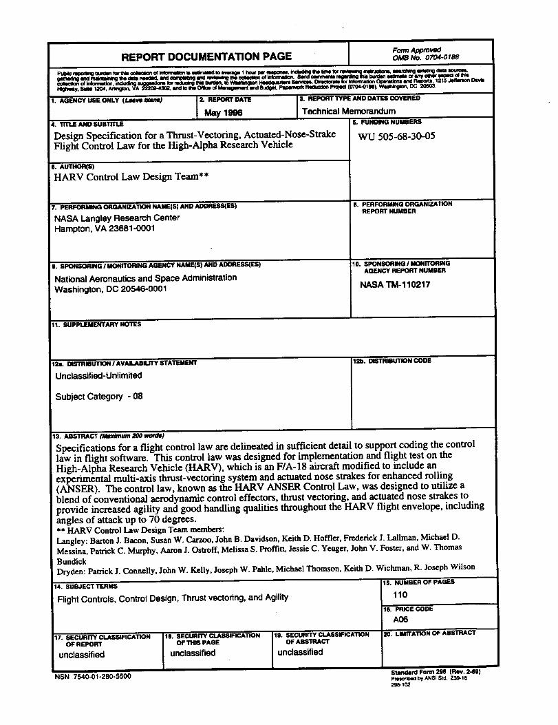
REPORT DOCUMENTATION PAGE I FormApprovedOMB No. 0704-0188
1. AGENCY USE ONLY (Leeve Jdank) 2. REPORT DATE 3. R_JPORT ,--vT_,i AND DATPJ COVi=J_cu
May 1996 Technical Memorandum4. TITLE AND SUBTITLE
Design Specification for a Thrust-Vectoring, Actuated-Nose-StrakeFLight Control Law for the High-Alpha Research Vehicle
6. A_B)
HARV Control Law Design Team**
7. PERFORMINGORGANIZATIONNAME(S) AND ADDRESSES)
NASA Langley Research Center
Hampton, VA 23681-0001
9. SPONSORINGI MONITORINGAGENCY NAME(S)AND ADORESS(ES)
National Aeronautics and Space Administration
Washington, DC 20546-0001
6. FUN_._IG NU;i_P.H:_
WU 505-68-30-05
0. PERFOK;,;;;,;: ORGANIZATION
REPORT NUMBER
:10. SPON_,_iNG I ItiOkn | G,_;;,IG
AGENCY REPORT NUMBER
NASA TM-110217
11. SUPPLEMENTARY NOTES
'12a. DISTRIBUTION I AVAILABILITY STATEMP.Ni
Unclassified-Unlimited
Subject Category - 08
12b. DI_;_;v"IK)N C_DE
13. ABSTRACT (Mint/mum 200 words)
Specifications for a flight control law are delineated in sufficient detail to support coding the controllaw in flight software. This control law was designed for implementation and flight test on theHigh-Alpha Research Vehicle (HARV), which is an F/A-18 aircraft modified to include anexperimental multi-axis thrust-vectoring system and actuated nose strakes for enhanced rolling(ANSER). The control law, known as the HARV ANSER Control Law, was designed to utilize ablend of conventional aerodynamic control effectors, thrust vectoring, and actuated nose strakes toprovide increased agility and good handling qualities throughout the HARV flight envelope, includingangles of attack up to 70 degrees.** HARV Control Law Design Team members:
Langley: Barton J. Bacon, Susan W. Carzoo, John B. Davidson, Keith D. Hoffler, Frederick J. Lallman, Michael D.Messina, Patrick C. Murphy, Aaron J. Ostroff, Melissa S. Proffitt, Jessie C. Yeager, John V. Foster, and W. Thomas
BundickDryden: Patrick J. Connelly, John W. Kelly, Joseph W. Pahle, Michael Thomson, Keith D. Wiehman, R. Joseph Wilson
14. SUBJECT TERMS
Flight Controls, Control Design, Thrust vectoring, and Agility
17. SECURITY CLASSIFICATION
OF REPORT
unclassified
16. SECIJNiT1 _ CLASSIFICATIONOF THIS PAGE
unclassified
NSN 7540-01-280-5500
10. SECIJMwTd CLASSIFICATIONOF ABSTRACT
unclassified
lS. NUMBER OF ppn_l:__
110
10. PRICE CODE
A06
20. UMn'ATION OF .A._,__--MACT
S.'--.-,,_rd FG,,-m, 298 (Rev. 2419)Pmscat_ by ANSi Sta. Z3S-_S296-102