design speci cation tricopter with stabilized camera 2 gps data: the tricopter’s position speci ed...
TRANSCRIPT

Design SpecificationTricopter with stabilized camera
Version 1.0
Author: Karl-Johan BarskDate: October 28, 2011
Status
Reviewed Karl-Johan Barsk 111007Approved Fredrik Lindsten
Course name: Control Project E-mail: [email protected] group: Triforce Document responsible: Karl-Johan BarskCourse code: TSRT10 Author’s E-mail: [email protected]: Tricopter Document name: design specification tricopter.pdf

Project Identity
Group E-mail: [email protected]: http://www.isy.liu.se/edu/projekt/tsrt10/2011/trikopter/Orderer: Fredrik Lindsten, Linkoping University
Phone: +46 13 - 28 13 65, E-mail: [email protected]: David Tornqvist, Linkoping University
Phone: +46 13 - 28 18 82 , E-mail: [email protected] Responsible: David Tornqvist, Linkoping University
Phone: +46 13 - 28 18 82, E-mail: [email protected] Manager: Josefin KemppainenAdvisors: Manon Kok, Linkoping University
Phone: +46 13 - 28 40 43 , E-mail: [email protected]
Group Members
Name Responsibility Phone E-mail(@student.liu.se)
Josefin Kemppainen Project Manager 070 - 866 56 75 joske208Karl-Johan Barsk Documents 070 - 788 95 48 karba878Joakim Hallqvist Firmware 070 - 571 37 64 joaha738Patrik Johansson Hardware 070 - 299 47 48 patjo855Rasmus Jonsson Software 070 - 999 30 19 rasjo160Johan Larsson Tests 070 - 747 87 78 johla342Mattis Lorentzon Information 070 - 592 32 66 matlo622Bjorn Rodseth Designer 070 - 274 52 20 bjoro826

Document History
Version Date Changes made Sign Reviewer
0.1 111003 First draft. KJB Karl-Johan Barsk0.2 111004 Second draft. KJB Karl-Johan Barsk0.3 111005 Third draft. KJB Karl-Johan Barsk1.0 111007 Fourth draft. KJB Karl-Johan Barsk
Course name: Control Project E-mail: [email protected] group: Triforce Document responsible: Karl-Johan BarskCourse code: TSRT10 Author’s E-mail: [email protected]: Tricopter Document name: design specification tricopter.pdf

Contents
1 Introduction 1
2 Definitions 1
2.1 Signal definitions . . . . . . . . . . . . . . . . . . . . . . . . . . . . . . . . . . . . . . . . . 1
2.2 Orientation . . . . . . . . . . . . . . . . . . . . . . . . . . . . . . . . . . . . . . . . . . . . 2
3 System overview 2
3.1 I2C . . . . . . . . . . . . . . . . . . . . . . . . . . . . . . . . . . . . . . . . . . . . . . . . 2
4 Ground station 3
4.1 Hardware . . . . . . . . . . . . . . . . . . . . . . . . . . . . . . . . . . . . . . . . . . . . . 3
4.2 Interface . . . . . . . . . . . . . . . . . . . . . . . . . . . . . . . . . . . . . . . . . . . . . . 4
4.3 Software . . . . . . . . . . . . . . . . . . . . . . . . . . . . . . . . . . . . . . . . . . . . . . 4
4.3.1 Functionality . . . . . . . . . . . . . . . . . . . . . . . . . . . . . . . . . . . . . . . 4
4.3.2 APM Mission Planner . . . . . . . . . . . . . . . . . . . . . . . . . . . . . . . . . . 5
4.3.2.1 Modifications in Flight Planner tab . . . . . . . . . . . . . . . . . . . . . 5
4.3.2.2 Modifications in Flight Data tab . . . . . . . . . . . . . . . . . . . . . . . 6
5 Flight unit 7
5.1 Hardware . . . . . . . . . . . . . . . . . . . . . . . . . . . . . . . . . . . . . . . . . . . . . 8
5.2 Interface . . . . . . . . . . . . . . . . . . . . . . . . . . . . . . . . . . . . . . . . . . . . . . 9
5.2.1 Internal communication . . . . . . . . . . . . . . . . . . . . . . . . . . . . . . . . . 9
5.3 Firmware . . . . . . . . . . . . . . . . . . . . . . . . . . . . . . . . . . . . . . . . . . . . . 9
5.3.1 ArduPilot . . . . . . . . . . . . . . . . . . . . . . . . . . . . . . . . . . . . . . . . . 10
5.3.1.1 Autonomous mode . . . . . . . . . . . . . . . . . . . . . . . . . . . . . . . 10
5.3.1.2 Manual mode . . . . . . . . . . . . . . . . . . . . . . . . . . . . . . . . . . 10
6 Surveillance unit 11
6.1 Hardware . . . . . . . . . . . . . . . . . . . . . . . . . . . . . . . . . . . . . . . . . . . . . 11
6.1.1 Gimbal . . . . . . . . . . . . . . . . . . . . . . . . . . . . . . . . . . . . . . . . . . 11
6.1.2 IMUCamera . . . . . . . . . . . . . . . . . . . . . . . . . . . . . . . . . . . . . . . . 12
6.2 Interface . . . . . . . . . . . . . . . . . . . . . . . . . . . . . . . . . . . . . . . . . . . . . . 12
6.3 Firmware . . . . . . . . . . . . . . . . . . . . . . . . . . . . . . . . . . . . . . . . . . . . . 12
6.3.1 GPS and coordinate Systems . . . . . . . . . . . . . . . . . . . . . . . . . . . . . . 13
6.3.2 Target Tracking . . . . . . . . . . . . . . . . . . . . . . . . . . . . . . . . . . . . . 14
6.4 Simulation . . . . . . . . . . . . . . . . . . . . . . . . . . . . . . . . . . . . . . . . . . . . . 14
6.4.1 Modeling of Gimbal . . . . . . . . . . . . . . . . . . . . . . . . . . . . . . . . . . . 14
7 Sensor unit 15
7.1 Hardware . . . . . . . . . . . . . . . . . . . . . . . . . . . . . . . . . . . . . . . . . . . . . 15
7.1.1 Sonar . . . . . . . . . . . . . . . . . . . . . . . . . . . . . . . . . . . . . . . . . . . 15
7.1.2 GPS . . . . . . . . . . . . . . . . . . . . . . . . . . . . . . . . . . . . . . . . . . . . 16
7.1.3 Magnetometer . . . . . . . . . . . . . . . . . . . . . . . . . . . . . . . . . . . . . . 16
7.1.4 Barometer . . . . . . . . . . . . . . . . . . . . . . . . . . . . . . . . . . . . . . . . . 16
7.2 Interface . . . . . . . . . . . . . . . . . . . . . . . . . . . . . . . . . . . . . . . . . . . . . . 16
8 Communication unit 16

8.1 Hardware . . . . . . . . . . . . . . . . . . . . . . . . . . . . . . . . . . . . . . . . . . . . . 17
8.1.1 XBee . . . . . . . . . . . . . . . . . . . . . . . . . . . . . . . . . . . . . . . . . . . 17
8.1.2 Radio controller . . . . . . . . . . . . . . . . . . . . . . . . . . . . . . . . . . . . . 17
8.2 Interface . . . . . . . . . . . . . . . . . . . . . . . . . . . . . . . . . . . . . . . . . . . . . . 18
A Wiring diagram 19
Course name: Control Project E-mail: [email protected] group: Triforce Document responsible: Karl-Johan BarskCourse code: TSRT10 Author’s E-mail: [email protected]: Tricopter Document name: design specification tricopter.pdf

Tricopter 1
1 Introduction
During the project the group will construct a surveillance system made up of a UAV(Unmanned Aerial Vehicle) with a mounted camera. The user will be able to specify aflying route along with specific points of interest for surveillance and the UAV will thenperform the surveillance mission. This will be referred to as the autonomous flight mode.During the flight a video stream from the camera will be broadcasted to a ground station.
Additionally to the autonomous flight mode will be a manual flight mode. The manualmode is for manual control of the tricopter with two optional safety features to preventaccidents, this will allow for unexperienced pilots to try out the equipment without riskingdamage to it. These are:
1. A virtual box with pre-specified boundaries. If this feature is enabled and the userbreaches the boundaries an auto-pilot will take control of the tricopter and fly itback to the center of the virtual box.
2. Easy-control, which when enabled translates the user control signals to directioncommands in a fixed coordinate system instead of directly forwarding the signals tothe rotors.
2 Definitions
APM ArduPilot MegaArduCopter Open source control system for model multicopterIMU Inertial Measurement UnitIMU-shield Sensor module with accelerometers, gyroscopes, magneto-
meters and a barometerArduPilot The autopilot of the tricopterIMUcopter An IMU-shield conntected to the ArduPilotArduPilot board The ArduPilot and IMUcopter together as one unitESC Electronic Speed ControllerGPS Global Positioning SystemGUI Graphical User InterfaceIMU Inertial Measurement UnitRC Radio ControlUAV Unmanned Aerial VehicleXBee Wireless modemI2C Inter-Integrated CircuitIMUcamera IMU-module with an IMU and a processor mounted on the GimbalAV Audio video
2.1 Signal definitions
Tricopter heading: The heading of the tricoper in degrees from the magnetometer tocompensate for the drift in the raw gyro on the GPS and the IMUcopter.
Tricopter orientation: The roll, pitch and yaw of the tricopter in degrees and thealtitude in dm.
Target location: The latitude and longitude of the target in degrees and the altitudein dm.
Course name: Control Project E-mail: [email protected] group: Triforce Document responsible: Karl-Johan BarskCourse code: TSRT10 Author’s E-mail: [email protected]: Tricopter Document name: design specification tricopter.pdf

Tricopter 2
GPS data: The tricopter’s position specified in latitude and longitude (degrees), thealtitude1 in dm and the speed of the tricopter in cm/s.
2.2 Orientation
If the tricopter is seen from above and the arm with the tail pan servo is pointing south,then the arm pointing north-east will be called right and the one pointing north-west willbe called left.
3 System overview
The UAV consists of a tricopter with an ArduCopter platform. ArduCopter is basedon the open source autopilot ArduPilot and is one of the most sophisticated IMU-basedautopilots on the market. It provides, among other things, full UAV functionality withscripted waypoints, manual RC control and more.
The tricopter consists of a Ground Station, a Flight unit, a Surveillance unit, a Sensorunit and a Communication unit. The relation of these subsystems can been seen in figure1.
For more information about the ArduPilot, see [1].
Figure 1: Block diagram for the system. For further descriptions of the subsystems, seesection 4 for the Ground station, section 5 for the Flight unit, section 6 for the Surveillanceunit, section 7 for the Sensor unit and section 8 for the Communication unit.
3.1 I2C
Mentioned below in the interface sections of the Flight unit, the Surveillance unit andthe Sensor unit (sections 5.2, 6.2 and 7.2 respectively) is the I2C bus. On this bus, the
1Due to the fact that a barometer will be used to decide the altitude this information will be redundant.
Course name: Control Project E-mail: [email protected] group: Triforce Document responsible: Karl-Johan BarskCourse code: TSRT10 Author’s E-mail: [email protected]: Tricopter Document name: design specification tricopter.pdf

Tricopter 3
ArduPilot will be acting as master. It will be written i C using the Arduino Wire library.
I2C uses two bidirectional lines named Serial Data Line (SDA) and Serial Clock (SCL),pulled up by resistors. As the name states, the former is used for sending the data andthe later for the clock.
4 Ground station
Figure 2: Block diagram for the Ground station with ingoing and outgoing signals.
The Ground station consists of two computers and one Radio Controller (RC). The Groundstation is primarily used to control the tricopter from the ground, either with the RC (inmanual mode) or the autonomous mode. It will also receive orientation of the tricopterfrom the Communication unit, see section 8. One of the computers is dedicated to receiv-ing the analogue video signal from the camera, named Laptop 1. The other is equippedwith the software APM Mission Planner and communicates with the tricopter viaXBee, see section 8.1.1. This computer is named Laptop 2.
See figure 2 for the outline of the unit.
4.1 Hardware
The Ground station consists of:
• iTheater glasses
• Wireless AV receiver
• Two laptops
• RC
• XBee module
The wireless AV receiver will receive analog video signals from the wireless video link atthe tricopter. To watch this video, iTheater glasses can be used. The laptop 2 will beable to play back the captured video by receiving the video signal from laptop 1 via acomposite video cable.
For laptop to tricopter communication, the Xbee module will be used, connected to Laptop2 through an USB-port. It will send and receive signals to and from the Xbee on thetricopter. For more information on the XBee, see section 8.1.1.
Course name: Control Project E-mail: [email protected] group: Triforce Document responsible: Karl-Johan BarskCourse code: TSRT10 Author’s E-mail: [email protected]: Tricopter Document name: design specification tricopter.pdf

Tricopter 4
4.2 Interface
The interface between the Ground station and the other units, namely the Communicationunit, and the Surveillance unit, is described here.
Signals in
• Analogue video signal from the video link in the Surveillance unit.
• Updated UAV flight data, i.e. tricopter orientation and GPS data according tosection 2.1, from the Communication unit transmitted over XBee.
Signals out
• Control signals to the Communication unit via the RC.
• Updated route/target coordinates to the Communication unit over XBee.
4.3 Software
For the required functionality of the project, there will be a need to create software forhandling transmission of data and parameters, playback of video, and also for loggingof the data. There already exists an open source program with a graphic interface forsimulation and programming of the ArduCopter chipset. This program is called APMMission Planner, [2], and can be modified to fit our specific goals and purposes, whilemaintaining a user-friendly environment. The software will be executed on laptop 2.
4.3.1 Functionality
The functionality of the software can be divided and listed in two parts, one with requiredfunctionality and one with optional. The required functionalities are linked to the contentsof the requirement specification, [5], representing priority one requirements of the groundstation. The optional functionalities corresponds to priority two requirements that willbe implemeted if time allows it.
Course name: Control Project E-mail: [email protected] group: Triforce Document responsible: Karl-Johan BarskCourse code: TSRT10 Author’s E-mail: [email protected]: Tricopter Document name: design specification tricopter.pdf

Tricopter 5
Table 1: Required functionality
Functionality Description
Waypoints via XBee. Send waypoints of the flight route over the XBee.Target point via XBee. Send the position of the target over the XBee.Tricopter position and orienta-tion via XBee
Receive data about the tricopter’s position and ori-entation over the XBee.
Playback of video Display the video feed in VLC player on computer.Size of the box Set the size of the Virtual Box offline.
Table 2: Optional functionality
Functionality Description
Size of the Box (wireless) Send and receive parameters that determine the sizeof the Virtual Box via XBee.
Target in sight flag Present status flag that indicates that the target isin sight and within a 40m radius from the tricopter.
Flight mode Display or change the mode of the tricopter. Au-tonomous or manual mode.
Virtual Box/Easy-Control fea-tures
Display or change which features are active.
Orientation of the camera Receive the orientation, pan and tilt angle, of thecamera.
The attributes presented above, will first be implemented as functions in an applicationthat can be executed from a terminal window. When all the functionality works, thenext step will be to modify the APM Mission Planner to handle the functions, whichremoves the need for the external application.
4.3.2 APM Mission Planner
The APM Mission Planner is an off-the-shelf software with much of the functionalityrequired for the project already at hand, such as updating the firmware, setting controllerparameters and, as the name suggests, planning waypoints for a flight route. At themoment though, it is only possible to transfer data and parameters while connected to thetricopter by wire. It is desirable to insert the implemented functionality, see section 4.3.1,into the user interface to make it more user-friendly. All modifications of the interface areoptional.
The features of the APM Mission Planner are located in a number of tabs in the mainwindow. The tabs where modifications will be made are labeled Flight Planner and FlightData. Screen prints of the two tabs can be seen in figure 3 and figure 4, respectively.
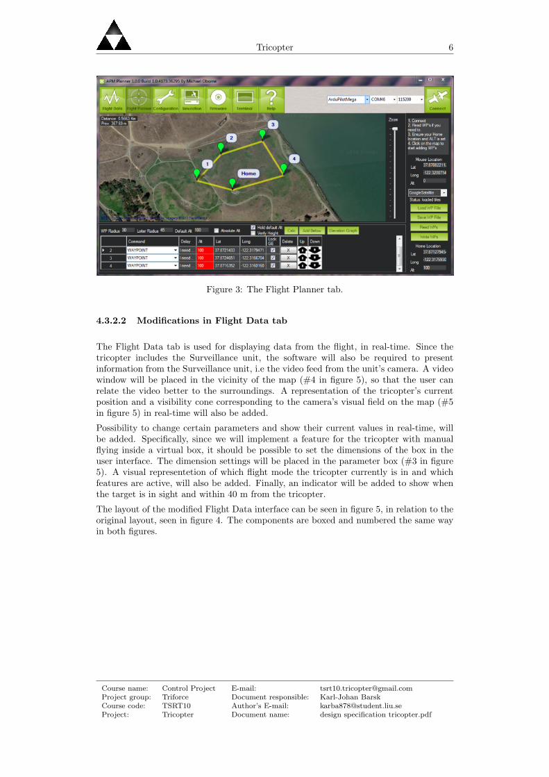
4.3.2.1 Modifications in Flight Planner tab
The Flight Planner tab, see figure 3, is used for defining an intended flight route by usingwaypoints. The waypoints are presented on a map but since the camera will be able tolock on a target, this target should have its own representation on the map. Thus, wewill want the ability to add one specific target point, and that one should be easy todistinguish from the route’s waypoints. The user interface will be modified so that it ispossible to choose what kind of point the user desires to add.
Course name: Control Project E-mail: [email protected] group: Triforce Document responsible: Karl-Johan BarskCourse code: TSRT10 Author’s E-mail: [email protected]: Tricopter Document name: design specification tricopter.pdf
Tricopter 6
Figure 3: The Flight Planner tab.
4.3.2.2 Modifications in Flight Data tab
The Flight Data tab is used for displaying data from the flight, in real-time. Since thetricopter includes the Surveillance unit, the software will also be required to presentinformation from the Surveillance unit, i.e the video feed from the unit’s camera. A videowindow will be placed in the vicinity of the map (#4 in figure 5), so that the user canrelate the video better to the surroundings. A representation of the tricopter’s currentposition and a visibility cone corresponding to the camera’s visual field on the map (#5in figure 5) in real-time will also be added.
Possibility to change certain parameters and show their current values in real-time, willbe added. Specifically, since we will implement a feature for the tricopter with manualflying inside a virtual box, it should be possible to set the dimensions of the box in theuser interface. The dimension settings will be placed in the parameter box (#3 in figure5). A visual representetion of which flight mode the tricopter currently is in and whichfeatures are active, will also be added. Finally, an indicator will be added to show whenthe target is in sight and within 40 m from the tricopter.
The layout of the modified Flight Data interface can be seen in figure 5, in relation to theoriginal layout, seen in figure 4. The components are boxed and numbered the same wayin both figures.
Course name: Control Project E-mail: [email protected] group: Triforce Document responsible: Karl-Johan BarskCourse code: TSRT10 Author’s E-mail: [email protected]: Tricopter Document name: design specification tricopter.pdf

Tricopter 7
Figure 4: The original layout of the Flight Data tab.
Figure 5: Sketch of the modified Flight Data tab.
5 Flight unit
The purpose of the flight unit is to fly the tricopter according to the commands receivedfrom the Ground station. It will also manage the sensor data from the Sensor unit, seesection 7 and control the Gimbal, see section 6.1.1. It consists of three rotors, one tail panservo and the ArduPilot chipset. Note that though the GPS is mounted on the ArduPilotchipset it is considered a part of the Sensor unit, see section 7. See figure 6 for the outline
Course name: Control Project E-mail: [email protected] group: Triforce Document responsible: Karl-Johan BarskCourse code: TSRT10 Author’s E-mail: [email protected]: Tricopter Document name: design specification tricopter.pdf

Tricopter 8
of the unit.
Figure 6: Block diagram for the Flight unit with ingoing and outgoing signals.
5.1 Hardware
The Flight unit consists of:
• ArduPilot Mega - Arduino Compatible UAV Controller w/ ATMega2560
• Three rotors and a tail pan servo
• EM-406/uBlox/MTK Adapter Cable 5 cm
• ArduPilot Mega IMU Shield/OilPan Rev-H (With Pins) [IMUcopter]
The ArduPilot Mega, which is an IMU-based open source autopilot, will be used to con-trol the tricopter by sending signals to both the servo on the tail and to the three ESCswhich control the three rotors. The main board which is designed with an ATMega2560micro controller will be placed as close as possible to the tricopters center of mass. TheIMUCopter will be mounted on the ArduPilot and with help of the GPS and the sonarfrom the Sensor unit, see section 7, the ArduPilot Mega becomes a fully functional au-topilot for a UAV.
The ArduPilot IMU on the Flight unit, called IMUcopter, is used to take measurements ofvelocity, position and orientation of the tricopter for the ArduPilot Mega. The processoron ArduPilot Mega is used to process the measurements from the IMUcopter as well as
Course name: Control Project E-mail: [email protected] group: Triforce Document responsible: Karl-Johan BarskCourse code: TSRT10 Author’s E-mail: [email protected]: Tricopter Document name: design specification tricopter.pdf
Tricopter 9
measurements from barometer, magnetometer, sonar and GPS, which are a part of thesensor unit. The IMUcopter consists of the regular functionality of an IMU, which hastriple axis accelerometers and triple axis gyros.
5.2 Interface
This section describes the communication of the Flight unit.
Signals in
• GPS data, see definition in section 2.1, from the Sensor unit via the I2C bus andserial ports.
• Tricopter heading, see definition in section 2.1, from the Sensor unit via the I2C busand serial ports.
• Altitude from the sonar sensor, see section 7.1.1, in the Sensor unit via the I2C busand serial ports.
• Altitude from the barometer, see section 7.1.4, in the Sensor unit via the I2C busand serial ports.
• Control signals from the Communication unit.
• Route/target coordinates from the Communication unit.
Signals out
• Updated UAV flight data, i.e. tricopter orientation and GPS data according tosection 2.1, to the Communication unit.
• The Flight unit provides the Surveillance unit with heading and GPS position dataand via an I2C bus.
5.2.1 Internal communication
The communication between IMUcopter and ArduPilot is serial and will not be modifiedfurther. Henceforth, IMUcopter and ArduPilot will be considered as one device in termsof communication with other components.
5.3 Firmware
The firmware on the flight unit is run on the ArduPilot board which is responsible for:
• Processing all sensor data from IMUcopter.
• Processing the flight commands.
• Sending control signals to the tricopter’s rotors and servo.
• Sending data to IMUcamera.
Course name: Control Project E-mail: [email protected] group: Triforce Document responsible: Karl-Johan BarskCourse code: TSRT10 Author’s E-mail: [email protected]: Tricopter Document name: design specification tricopter.pdf

Tricopter 10
5.3.1 ArduPilot
The ArduPilot is a complete control system running on an Arduino base. It receivescommands from the RC controller and ground station and uses the information fromthe IMUcopter to stabilize the tricopter while performing these commands. It’s alsoresponsible for the autonomous flight mode. Its output signals are control signals for therotors, tail pan servo and flight information to the ground station.
The board is delivered with open source firmware that fuses sensor information from theIMUcopter to get estimates of the tricopter’s position and orientation.
Most of the ArduPilot’s functionality already exists in the firmware but some things haveto be added:
• Functionality to send target coordinates to the IMUcamera over I2C bus.
• Functionality to send position and orientation estimates to the IMUcamera over I2Cbus.
• Functionality for virtual box feature in manual mode.
• Functionality for easy control feature in manual mode.
5.3.1.1 Autonomous modePerforming autonomous flight is a matter of translating route information to controlsignals for the rotors and tail pan servo. The route information consists of predefinedwaypoints that the tricopter should pass through. Using sensor information to estimateposition, velocity and orientation makes it possible to adjust the control signals to steerthe tricopter in the right direction. The sensor information is hardware filtered on theIMUcopter and then fused on the ArduPilot to get the estimates. The route informationalso contains desired take-off and landing coordinates.
The autonomous flight mode will be performed using already existing functionality in theArduPilot firmware but will be modified if the group finds room for improvement.
5.3.1.2 Manual modeIn manual mode the user controls the tricopter using an RC controller. How the controlsignals are interpreted depends on which features that have been enabled.
Virtual box feature: The Virtual box feature is used to confine the flight space for thetricopter. If the boundaries of the box are broken the tricopter will return to thecenter of the box. The box default size is 5x5x5 [m], but can be altered, and thebox center is determined by the tricopter’s position when the feature is activated.If there is a risk of the tricopter crashing because the box is placed to close to theground the box will automatically be elevated to a safer height. The box is orientedso the sides are parallel to the longitude and latitude lines.
Easy control feature: When this feature is activated a fix coordinate system is createdand aligned to the tricopter heading at that moment. As long as this feature is activeall control commands are interpreted as desired flight directions in this coordinatesystem and will be converted to rotor commands to follow them.
Course name: Control Project E-mail: [email protected] group: Triforce Document responsible: Karl-Johan BarskCourse code: TSRT10 Author’s E-mail: [email protected]: Tricopter Document name: design specification tricopter.pdf

Tricopter 11
6 Surveillance unit
The function of the Surveillance unit is to calculate the orientation of the Gimbal andthen control the camera. The purpose of the camera and the Gimbal is covered in theintroduction, see section 1.
Figure 7: Block diagram for the Surveillande unit.
6.1 Hardware
The Surveillance unit consists of:
• Camera
• Gimbal
• ArduImu+V2 [IMUcamera]
6.1.1 Gimbal
The Gimbal is the device on which the camera is mounted. It consists of two servos, oneto perform a panning movement and one to perform a tilting. This makes it possibleto move the camera independently of the UAV and thus make it stable according to theobject that the camera is focusing on.
The stabilization is done by having two separate IMUs, one on the UAV itself (IMUcopter)and one on the Gimbal (IMUcamera). Thanks to the GPS on the UAV and IMUcopter thecurrent pose is estimated and the location of the target is given. This is then translatedvia the subsystem G1 (see figure 8) to wanted angles (tilt and pan). The current anglesof the Gimbal (via IMUcamera and G2, see figure 8) is then subtracted from the onesfrom G1 and results in two reference angles to the feedback loops of the servos. Again,see figure 8.
Course name: Control Project E-mail: [email protected] group: Triforce Document responsible: Karl-Johan BarskCourse code: TSRT10 Author’s E-mail: [email protected]: Tricopter Document name: design specification tricopter.pdf

Tricopter 12
Figure 8: Block diagram for the control of the camera.
6.1.2 IMUCamera
The IMU on this unit – IMUCamera – will be placed strategically on the camera mountto determine the camera’s orientation, heading and to eventually stabilize it. It will havethe same sensors as the IMUcopter, but instead of being mounted on the ArduPilot, it willbe connected to it through the I2C-buss. Before mounting the IMUcamera, tests will bedone to see if the Gimbal can manage to control the camera without an IMU. The builtin regulators should be enough to get a good camera angle based on the servo angles.There is however a risk that the Gimbal’s position will not be sufficiently accurate dueto numerical errors. This is where the IMUcamera might be needed to provide with amore accurate information. The IMUcamera will send signals to the ArduPilot, whichwill calculate a reference signal for the camera and send it to the Gimbal’s servos.
6.2 Interface
The interface between the surveillance unit and the other units, Ground station and Flightunit, will be presented below.
Signals in:
• Tricopter orientation and target location, see definition in section 2.1, from theArduPilot in the Flight unit. The signals are transmitted via the I2C bus. TheIMUcamera will have address 2 on the bus.
Signals out:
• Video to Laptop 1 in the Ground station via the Video link.
6.3 Firmware
The only firmware on the unit is run on IMUcamera.
Two different alternatives to estimate the Gimbal’s position and orientation will be com-pared during the development process.
Alternative 1: The IMUcopter estimates for the tricopter position and orientation arerequested and used to calculate the position and orientation of the Gimbal base.
Course name: Control Project E-mail: [email protected] group: Triforce Document responsible: Karl-Johan BarskCourse code: TSRT10 Author’s E-mail: [email protected]: Tricopter Document name: design specification tricopter.pdf

Tricopter 13
From this the desired Gimbal servo angles are calculated. In this case the IMUcam-era is only used to calculate and set the servo angles, so the IMUcamera sensors willnot be used.
Alternative 2: The IMUcamera sensors are used to estimate the Gimbal orientationand combines this information with the position of the tricopter (received fromIMUcopter) to calculate the desired Gimbal servo angles.
In both alternatives, dynamic behaviour of the servos will be handled using a simple modelto account for the servo’s limited rotation speeds. Firmware for the fusion of the sensorinformation on the IMUcamera already exists but some things have to be added:
• Functionality to receive target coordinates from the ArduPilot over I2C bus.
• Functionality to receive position and orientation estimates from the ArduPilot overI2C bus.
• Functionality to calculate desired servo angles.
• Functionality to actuate desired servo angles.
6.3.1 GPS and coordinate Systems
The GPS module gives its position in longitude, latitude and elevation above sea level (ageographic coordinate system) according to the World Geodetic System (WGS 84) globalreference frame. Doing calculations in this system is quite troublesome so a cartesiancoordinate system is introduced.
This system is referred to as the earth coordinate system (E, see figure 9a). Its origin islocated at sea level on the straight line running through the earth center of mass and thetricopter position. Its z-axis points downwards along this line, its x-axis to the geographicnorth pole and its y-axis east (NED: north, east, down).
The orientation of the tricopter is given by a coordinate system fixed in its frame (T, seefigure 9b) and follows the standard for aircraft-fixed coordinate systems where the x-axisis pointing through the nose, the y-axis to the right and the z-axes are pointing down.
There is also a third coordinate system with the same orientation as T but with its originlocated in the Gimbals rotation point (G, see figure 9c).
x
y
z
E
(a) Earth coordinate sys-tem (E)
x
y
z
T
(b) Tricopter coordinate sys-tem (T)
x
y
z
G
(c) Gimbal coordinate sys-tem (G)
Figure 9: Coordinate systems.
Course name: Control Project E-mail: [email protected] group: Triforce Document responsible: Karl-Johan BarskCourse code: TSRT10 Author’s E-mail: [email protected]: Tricopter Document name: design specification tricopter.pdf

Tricopter 14
6.3.2 Target Tracking
The coordinate systems introduced in 6.3.1 make it relatively easy to calculate the requiredservo angles to point the camera in the target direction. It is only a matter of transformingthe target coordinates from the geographic coordinate system, (E, see figure 9c), to theGimbal coordinate system (G, see figure 9c) and then calculate the angles using simpletrigonometry.
6.4 Simulation
Simulation of the Gimbal will be done. The purpose of the simulation is to test controllerparameters offline, to avoid damaging the equipment, and to remove the need for timeconsuming set up of the hardware. Simulation of the Gimbal will be done in MatlabSimulink.
6.4.1 Modeling of Gimbal
To simulate the Gimbal, a mathematical model of it will be needed. A block schemeof the Gimbal model is presented in figure 10. There will also be a need for models ofthe sensors involved. The Gimbal has two servos which gives it two degrees of freedom.Ultimately, simulated pan and tilt angles for the Gimbal is achieved. To achieve this,information about the tricopter position and orientation, target coordinates, and theGimbal orientation is required.
Simulation of the Gimbal will focus on the stabilization of the camera. Therefore thedisturbances on the tricopter’s position and orientation are the main concern of the stabi-lization. These disturbances are, mainly, turbulence and sensor errors. Even in a simplecase such as the tricopter hovering in place, these are in effect and therefore only simula-tion for this case is required. If the Gimbal can handle the disturbances while hovering,it can be assumed that it can handle them during flight.
The signals from the IMUcopter are angles, angular velocities and angular accelerations.It also has the orientation from the magnetometer, which is a compass. The IMUcoptermodel also have values for longitude and latitude positions, and atmospheric pressuremeasurement. For more information about the firmware, see the sections 5.3 and 6.3.
Figure 10: Block scheme of the Gimbal model
Course name: Control Project E-mail: [email protected] group: Triforce Document responsible: Karl-Johan BarskCourse code: TSRT10 Author’s E-mail: [email protected]: Tricopter Document name: design specification tricopter.pdf

Tricopter 15
7 Sensor unit
To be able to fulfill the requirements specified by the project, additional sensors need tobe placed on the tricopter. These sensors will be described in this section. See figure 11for the outline of the unit.
Figure 11: Block diagram for the Sensor unit with ingoing and outgoing signals.
7.1 Hardware
The Sensor unit consists of:
• MB1200 XL-MaxSonar-EZ0 High Performance Ultrasonic Range Finder
• GS407 U-Blox5 GPS 4Hz (New Antenna & Free uBlox Adapter Basic)
• HMC5883L - Triple Axis Magnetometer
• A built-in barometer
7.1.1 Sonar
Since autonomous landing is a requirement in this project, a sonar sensor will be mountedon the tricopter for accurate altitude determination when the tricopter is close to groundlevel. At heights below approximately three meters, the sonar sensor, instead of the built-in barometer (section 7.1.4), will be used to determine the tricopters altitude. This sensorwill be placed on the main frame of the tricopter, facing the ground, with at least adistance of eight centimeters from the body to prevent the sonar sensor from picking upelectrical disturbances.
Course name: Control Project E-mail: [email protected] group: Triforce Document responsible: Karl-Johan BarskCourse code: TSRT10 Author’s E-mail: [email protected]: Tricopter Document name: design specification tricopter.pdf

Tricopter 16
7.1.2 GPS
To determine the position of the tricopter and enable waypoint navigation, a GPS modulewill be mounted on the tricopter. This GPS module will be connected to the ArduPilotboard.
7.1.3 Magnetometer
Since the tricopter is able to hover, the GPS will not be able to compensate for yaw gyrodrift. This is the case for both the sensors in IMUcopter and IMUcamera. To compensatefor this, the magnetometer will provide a heading of the tricopter to be used in both theFlight unit and the Surveillance unit.
The magnetometer will be mounted on IMUcopter via an I2C cable.
7.1.4 Barometer
The barometer will be used to decide the altitude of the tricopter when the tricopter isthree or more meters above the ground. This is done by measuring the air pressure.
The barometer is physically mounted on IMUcopter.
7.2 Interface
This section describes the communication of the Sensor unit.
Signals in
This unit has no signals in.
Signals out
• GPS data serially, see definition in section 2.1, to the Flight unit via the GPS porton the ArduPilot board.
• Magnetometer aquired signals to the Flight unit via an I2C bus with address 0x1Eon the ArduPilot board.
• Sonar sensor aquired signals to the Flight unit via the Pitot tube on the ArduPilotboard.
• Barometer aquired signals to the Flight unit via the I2C bus with address 0x77 onthe ArduPilot board.
8 Communication unit
This section covers the wireless communication between the tricopter and the groundstation. Figure 12 below is an overview of the communication unit.
Course name: Control Project E-mail: [email protected] group: Triforce Document responsible: Karl-Johan BarskCourse code: TSRT10 Author’s E-mail: [email protected]: Tricopter Document name: design specification tricopter.pdf

Tricopter 17
Figure 12: Block diagram for the Communication unit with ingoing and outgoing signals.
8.1 Hardware
The Communication unit consists of:
• Xbee Pro 900 Wire Ant
• Xbee Pro 900 RP-SMA Ant
• Multiplex Royal 9 evo
• AR7000 DSM2 7-Channel Receiver
8.1.1 XBee
The Xbee on the will be connected to the ArduPilot and communicate while airborne withthe Xbee on the ground, connected to Laptop 2. It will be used for updating parameters,tracking sensor outputs, setting flight paths and target coordinates.
8.1.2 Radio controller
The radio controller will be used for controlling the tricopter in the manual mode, it willalso be able to change the tricopter into autonomous mode and back.
The signals from the RC are sent to a receiver on the tricopter and are then forwarded tothe ArduPilot.
Course name: Control Project E-mail: [email protected] group: Triforce Document responsible: Karl-Johan BarskCourse code: TSRT10 Author’s E-mail: [email protected]: Tricopter Document name: design specification tricopter.pdf

Tricopter 18
8.2 Interface
The interface between the communication unit and the other units , Ground station andFlight unit, will be presented below.
Signals in:
• Control signals from the RC control in the Ground station.
• Updated route/target coordinates over XBee from the Ground station.
Signals out:
• Control signals to the ArduPilot in the Flight unit from the RC.
• Updated route/target coordinates to the ArduPilot in the Flight unit over XBee.
Course name: Control Project E-mail: [email protected] group: Triforce Document responsible: Karl-Johan BarskCourse code: TSRT10 Author’s E-mail: [email protected]: Tricopter Document name: design specification tricopter.pdf

Tricopter 19
A Wiring diagram
Course name: Control Project E-mail: [email protected] group: Triforce Document responsible: Karl-Johan BarskCourse code: TSRT10 Author’s E-mail: [email protected]: Tricopter Document name: design specification tricopter.pdf

Tricopter 20
References
[1] v/a, arducopter – Arduino-based autopilot for mulitrotor craft, from quadcopters totraditional helis. http://code.google.com/p/arducopter/, 2011-09-02.
[2] v/a, ardupilot-mega – Official ArduPilot Mega repository.http://code.google.com/p/ardupilot-mega/wiki/Mission, 2011-09-05.
[3] v/a, FlightGear – sophisticated, professional, open-source flight simulation.http://www.flightgear.org/, 2011-09-09.
[4] Atmel, 8-bit Atmel Microcontroller with 64K/128K/256K Bytes In-System Pro-grammable Flash. http://www.atmel.com/dyn/resources/prod documents/doc2549.pdf,may 2011.
[5] Barsk, Karl-Johan, Requirement specification - Tricopter with stabilized camera version1.1. oct 2011.
Course name: Control Project E-mail: [email protected] group: Triforce Document responsible: Karl-Johan BarskCourse code: TSRT10 Author’s E-mail: [email protected]: Tricopter Document name: design specification tricopter.pdf