design report - calvin college report.… · this report details the research and design of the jet...
TRANSCRIPT

Design Report
Team 6: Josh Vanderbyl
Zak DeVries Nico Ourensma
Ryan DeMeester
Calvin College May 13, 2015
Advisor: Professor Ned Nielsen

1
©2015
Josh Vanderbyl, Zak DeVries, Nico Ourensma, Ryan DeMeester and Calvin College

2
Executive Summary This report details the research and design of the Jet Blade. The Jet Blade is a new and
unique personal watercraft. The goal of Team 6 is to design a personal watercraft (PWC)
that will provide the user with an unparalleled experience in water sports activities. The
Jet Blade is a single rider personal watercraft that is stable yet agile. It incorporates a
three-ski design that utilizes two skis in the front of the craft and one ski in the rear.
These skis are located in spaced relation below an aluminum hull and operate to hydro-
dynamically lift the Jet Blade to a cruise position by relative water flow upon the
undersides of the skis. The rear ski is attached to a horizontal jet pump that is powered
by a 650cc water-cooled engine. The front suspension implements an Active Tilt steering
design that allows for agility. Team 6, also known as Team Jet Blade, has chosen this
project for their senior design capstone project. The conclusion of the feasibility study is
that the manufacturing and functionality of the Jet Blade are feasible. After fabrication
and testing the Jet Blade functions successfully as a unique and exhilarating personal
watercraft.

3
Table of Contents Executive Summary ......................................................................................................................... 2
Table of Tables ................................................................................................................................. 6
Table of Figures ............................................................................................................................... 7
1 Introduction .................................................................................................................................. 9
1.1 The Project ............................................................................................................................ 9
1.2 Design Norms ........................................................................................................................ 9
1.2.1 Transparency ................................................................................................................. 9
1.2.2 Integrity.......................................................................................................................... 9
1.2.3 Trust ............................................................................................................................... 9
1.3 The Team ............................................................................................................................. 10
1.3.1 Team Roles ................................................................................................................... 11
2 Requirements ............................................................................................................................. 11
2.1 Safety................................................................................................................................... 11
2.2 Operating Conditions .......................................................................................................... 11
2.3 Functionality ........................................................................................................................ 12
2.4 Regulations .......................................................................................................................... 12
3 Project Management .................................................................................................................. 12
3.1 Project Breakdown .............................................................................................................. 12
3.1.1 Hull ............................................................................................................................... 13
3.1.2 Skis ............................................................................................................................... 13
3.1.3 Suspension and Steering .............................................................................................. 13
3.1.4 Propulsion System ....................................................................................................... 13
3.1.5 Control Systems ........................................................................................................... 13
3.2 Schedule .............................................................................................................................. 13
3.2.1 Task List ........................................................................................................................ 13
3.2.2 Schedule Implementation............................................................................................ 14
3.2.3 Task Specifications ....................................................................................................... 14
3.3 Budget ................................................................................................................................. 17
4 Research ..................................................................................................................................... 18
4.1 Hull Research....................................................................................................................... 18
4.2 Ski Research ........................................................................................................................ 19
4.3 Tilt Suspension Research ..................................................................................................... 20
4.4 Jet Pump Research .............................................................................................................. 22
4.5 Motor Research ................................................................................................................... 23

4
5 Design Process ............................................................................................................................ 23
5.1 Design Alternatives ............................................................................................................. 23
5.1.1 Hull ............................................................................................................................... 23
5.1.2 Skis ............................................................................................................................... 23
5.1.3 Suspension and Steering .............................................................................................. 24
5.1.4 Propulsion .................................................................................................................... 25
5.2 Design Decisions .................................................................................................................. 25
5.2.1 Hull ............................................................................................................................... 25
5.2.2 Skis ............................................................................................................................... 26
5.2.3 Suspension and Steering .............................................................................................. 26
5.2.4 Propulsion .................................................................................................................... 26
5.2.5 Control system ............................................................................................................. 27
5.3 Design .................................................................................................................................. 27
5.3.1 Hull ............................................................................................................................... 27
5.3.2 Skis ............................................................................................................................... 33
5.3.3 Suspension and Steering .............................................................................................. 37
5.3.4 Propulsion .................................................................................................................... 40
5.3.5 Complete Design .......................................................................................................... 41
5.4 Prototype Manufacturing.................................................................................................... 43
5.4.1 Hull and Frame ............................................................................................................. 43
5.4.2 Skis ............................................................................................................................... 45
5.4.3 Suspension and Steering .............................................................................................. 46
5.4.4 Final Assembly ............................................................................................................. 47
6 Testing ........................................................................................................................................ 49
6.1 Safety................................................................................................................................... 49
6.2 Launch Capabilities ............................................................................................................. 51
6.3 Strength ............................................................................................................................... 51
6.4 Performance and Handling ................................................................................................. 51
7 Business Plan .............................................................................................................................. 53
7.1 Market Competition ............................................................................................................ 53
7.2 Break-Even Analysis ............................................................................................................ 53
8 Conclusion .................................................................................................................................. 54
9 Acknowledgements .................................................................................................................... 54
10 Bibliography .............................................................................................................................. 55
Appendix A: Project Gantt Chart ................................................................................................... 55

5
Appendix B: EES Calculations ........................................................................................................ 57
Appendix C: FEA Analysis ............................................................................................................... 61

6
Table of Tables Table 1: Tasks for design and manufacturing of the Jet Blade ...................................................... 14 Table 2: Prototype Cost Breakdown .............................................................................................. 17 Table 3: Input Values ..................................................................................................................... 35 Table 4: Market Competition ........................................................................................................ 53 Table 5: Estimated Production Costs ............................................................................................. 53

7
Table of Figures Figure 1: Team Picture ................................................................................................................... 10 Figure 2: First Semester Gantt Chart ............................................................................................ 15 Figure 3: February Schedule .......................................................................................................... 15 Figure 4: March Schedule .............................................................................................................. 16 Figure 5: April Schedule ................................................................................................................. 16 Figure 6: May Schedule ................................................................................................................. 17 Figure 7: WetBike Schematic [1] ................................................................................................... 19 Figure 8: Pressure Distribution of a Flat Planing Surface [2] ......................................................... 20 Figure 9: Model of Swayspension [3] ............................................................................................ 21 Figure 10: Tilting Motor Works [4] ................................................................................................ 21 Figure 11: Jet Pump Schematic [1] ................................................................................................ 22 Figure 12: Motor and Pump Assembly .......................................................................................... 23 Figure 13: Initial Hull CAD Model .................................................................................................. 27 Figure 14: Redesigned Hull - Isometric View ................................................................................. 28 Figure 15: Redesigned Hull - Side View ......................................................................................... 28 Figure 16: Redesigned Hull - Top View .......................................................................................... 28 Figure 17: Redesigned Hull - Rear View ........................................................................................ 29 Figure 18: Redesigned Hull - Front View ....................................................................................... 29 Figure 19: Internal Frame Design .................................................................................................. 30 Figure 20: Bottom Hull with Frame FEA ........................................................................................ 30 Figure 21: Float Height without Rider ........................................................................................... 32 Figure 22: Float Height with 200 lb. Rider ..................................................................................... 32 Figure 23: Float Height with 410 lb. Rider ..................................................................................... 33 Figure 24: Front Ski CAD Model..................................................................................................... 34 Figure 25: Rear Ski CAD Model ...................................................................................................... 34 Figure 26: Definition of Inputs [5] ................................................................................................. 35 Figure 27: Results of Savitsky Procedures ..................................................................................... 36 Figure 28: Jet Blade During Planing Process .................................................................................. 36 Figure 29: WetBike During Planing Process .................................................................................. 36 Figure 30: Active Tilt Suspension ................................................................................................... 37 Figure 31: Active Tilt - Right Turn .................................................................................................. 38 Figure 32: Active Tilt – Straight ..................................................................................................... 38 Figure 33: Active Tilt - Left Turn .................................................................................................... 38 Figure 34: Compressed Suspension ............................................................................................... 39 Figure 35: Complete CAD Model ................................................................................................... 41 Figure 36: Complete Model – Front View ..................................................................................... 42 Figure 37: Complete Model – Right Turn ...................................................................................... 42 Figure 38: Complete Model – Left Turn ........................................................................................ 43 Figure 39: Internal Frame .............................................................................................................. 44 Figure 40: Hull and Frame Mock Up .............................................................................................. 44 Figure 41: Initial Float Test ............................................................................................................ 45 Figure 42: Complete Hull Assembly ............................................................................................... 45 Figure 43: Adjustable Shock Mount .............................................................................................. 46 Figure 44: Adjustable Steering Linkage Mount ............................................................................. 46 Figure 45: Completed Prototype - Front View before Paint ......................................................... 47
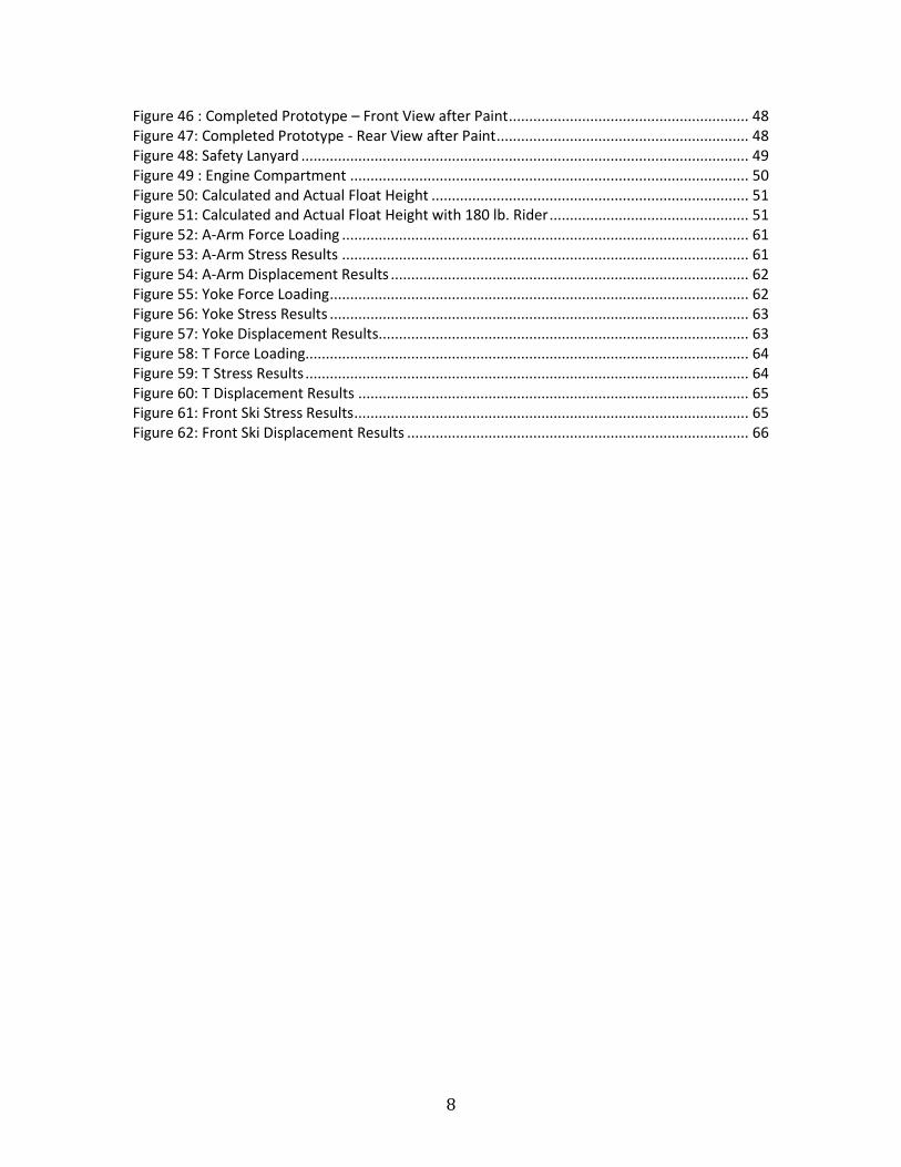
8
Figure 46 : Completed Prototype – Front View after Paint ........................................................... 48 Figure 47: Completed Prototype - Rear View after Paint .............................................................. 48 Figure 48: Safety Lanyard .............................................................................................................. 49 Figure 49 : Engine Compartment .................................................................................................. 50 Figure 50: Calculated and Actual Float Height .............................................................................. 51 Figure 51: Calculated and Actual Float Height with 180 lb. Rider ................................................. 51 Figure 52: A-Arm Force Loading .................................................................................................... 61 Figure 53: A-Arm Stress Results .................................................................................................... 61 Figure 54: A-Arm Displacement Results ........................................................................................ 62 Figure 55: Yoke Force Loading ....................................................................................................... 62 Figure 56: Yoke Stress Results ....................................................................................................... 63 Figure 57: Yoke Displacement Results........................................................................................... 63 Figure 58: T Force Loading............................................................................................................. 64 Figure 59: T Stress Results ............................................................................................................. 64 Figure 60: T Displacement Results ................................................................................................ 65 Figure 61: Front Ski Stress Results ................................................................................................. 65 Figure 62: Front Ski Displacement Results .................................................................................... 66
9
1 Introduction 1.1 The Project The goal of Team 6 was to design a personal watercraft (PWC) that provides the user with an
unparalleled experience in water sports activities. Jet Blade is designed to be safe, user friendly,
aesthetically pleasing, and exhilarating to ride. The design incorporates an aluminum hull,
suspension design, and skis that resemble similar structure to a snowmobile. However, the front
suspension implements a tilt steering design providing riders with a motorcycle feel on the
water, while still maintaining stability. This will allow for a wide variety of riders to enjoy the
performance of the Jet Blade. Cost, strength, quality of design, and manufacturability were all
considered in order to optimize the design of Jet Blade.
1.2 Design Norms
1.2.1 Transparency The Jet Blade has been designed to be easy to operate and its functionality is clear to the user.
In order for the Jet Blade to be successful it must be able to be used safely and easily by a wide
range of users. Maintenance and problem diagnosis of the machine must be clearly identified
and obvious to the user.
1.2.2 Integrity Honesty and decency must be maintained in the design, manufacturing, and presentation of the
Jet Blade. The Jet Blade will be easy to operate and intuitive for all riders.
1.2.3 Trust In order to meet the design norm of trust, the Jet Blade must be strong and reliable. It must be
able to endure sustained use and maintain performance. The Jet Blade needs to provide an
exhilarating experience while maintaining a feeling of safety for the rider.

10
1.3 The Team
Figure 1: Team Picture
The team consists of Josh Vanderbyl, Zak DeVries, Nico Ourensma, and Ryan DeMeester. Each
member of the team is part of the mechanical concentration of the engineering program at
Calvin College. The team shares great interest in the outdoors and water activities. Our passions
collided with our skills when the Jet Blade project was established.
Josh Vanderbyl: A Southern California native, Josh grew up in Beaumont, California. While
studying at Calvin College, Josh has had internships at Kerry Ingredients & Flavors as well as
Shape Corporation. At these internships Josh gained industry knowledge in project management
and lean manufacturing as well as developed skills in Solidworks CAD design.
Zak DeVries: Growing up in Byron Center, Michigan Zak began his engineering career at Lacks
Trim Systems where he learned the basics of lean production and the importance of continuous
improvement projects. He is currently working at Progressive Surface where he has developed
problem solving abilities and gained skills in Solidworks CAD design.
Nico Ourensma: Originally from Lake City, Iowa, Nico started his engineering design at The
Cardinal Group where he gained experience in Autodesk Inventor CAD design. He has more

11
recently held a position at Woodward, Inc. where he was involved in the testing of aircraft
turbine engine components.
Ryan DeMeester: Proudly from Pasadena, California, Ryan has had great internship experience
in west Michigan. From working on quality control for honeycomb materials at Plascore, to
performing time analysis studies at DeWys Manufacturing, Ryan has a wide variety of
experience that is the essential foundation of his problem solving and engineering skills.
1.3.1 Team Roles
Josh Vanderbyl: Josh is responsible for the design and manufacturing of the top hull and the
front and rear skis.
Zak DeVries: Zak is responsible for the design and modeling of the suspension, the bottom hull,
and the tilt steering of the Jet Blade.
Nico Ourensma: Nico is responsible for the design and manufacturing of the top hull, seat,
suspension, tilt steering, and the controls for the Jet Blade.
Ryan DeMeester: Ryan is responsible for assisting with design and manufacturing of the bottom
hull, the seat, and the front and rear skis. He is also in charge of designing and updating the
team website.
2 Requirements 2.1 Safety As with any recreational vehicle, user safety is very important. Riders need to feel safe and
secure while riding the Jet Blade. The hull must be water tight and dependably buoyant. It must
feel stable once on plane and be easily controlled so collisions can be avoided. Most personal
watercraft (PWC) injuries result from running into docks, other watercraft, or other objects. For
this reason, maneuverability is very important. As with any personal watercraft, a kill switch
must be implemented to prevent a runaway vehicle scenario.
2.2 Operating Conditions The Jet Blade is designed to operate optimally in flat water conditions. However it has still been
engineered to operate in moderate to rough conditions while maintaining stability. The
watercraft's front Active Tilt suspension is able to absorb waves and the front skis are designed
12
to cut through them in order to provide the operator with a smooth ride. The Jet Blade is
designed for use on small inland lakes where waves should not exceed 1-2' in amplitude. Like
most watercraft, it is a seasonal vehicle. It is able to operate in water temperatures down to
32oF, however this is well below comfortable riding temperatures. Conversely, the liquid cooled
650cc engine allows the Jet Blade to stay cool even on the hottest summer days, operating in
water temperatures up to 90oF.
2.3 Functionality The Jet Blade is a single rider personal watercraft that is stable yet agile. The function of the Jet
Blade is to be a recreational vehicle used on water. The three-ski design utilizes two skis in the
front of the craft, and one ski in the rear. These skis are located in spaced relation below an
aluminum hull and operate to hydro-dynamically lift the Jet Blade to a cruise position by relative
water flow upon the undersides of the skis. This will allow the rider to have a controlled and
comfortable ride at cruising speeds. The front suspension implements a tilt steering design that
will allow for the agility. The Jet Blade is designed to be trailered, loaded, and unloaded with
only one person.
2.4 Regulations The Jet Blade must be registered by the State of Michigan. It must also have current registration
stickers in order to be operated in any body of water in Michigan. The Jet Blade is designed to
be usable by a wide variety of rides. In the State of Michigan any rider 14 and older with a
boater’s safety license is able to operate the Jet Blade.
3 Project Management 3.1 Project Breakdown The project was broken down into five categories, each of which have a significant role in the
final outcome of the design. The five categories of the project include the hull, skis, suspension
and steering system, propulsion system, and the control system. Each member of the team was
responsible for certain categories and had authority in the design and manufacturing. The whole
team worked together to make sure each was done well.

13
3.1.1 Hull The hull is the foundation of the Jet Blade. It is strong and rigid enough to withstand the weight
of the rider and engine while remaining light enough to provide significant performance. The
hull also provides enough buoyancy to keep the Jet Blade and the rider comfortably floating in
the water.
3.1.2 Skis The three-ski design utilizes two skis in the front of the craft and one ski in the rear. The Jet
Blade, when being operated, begins with the skis and a portion of the craft submerged. As the
speed increases the skis begin to plane until the Jet Blade is completely out of the water and
riding solely on the skis. While the skis are submerged there is little control of the vehicle. This is
why it is important to design the skis large enough so that the Jet Blade can plane quickly.
3.1.3 Suspension and Steering Conventional personal watercraft rely on a directional water jet to steer. Jet Blade is unique in
that the jet is fixed and steering is accomplished by turning the front skis. In order to achieve
maximum turning performance, both skis must remain in contact with the water at all
times. This requires the implementation of a tilting suspension system.
3.1.4 Propulsion System Similar to most personal watercraft, Jet Blade implements a jet pump for thrust. A right angle
gear box connects the impeller to a vertical-shaft engine. As the engine and pump assembly are
the largest components, the Jet Blade is essentially built around the propulsion system.
3.1.5 Control Systems Certain control systems are required for basic operation and safety. These include start and
stop switches, an electronic choke, and a kill switch. In addition, gauges have been
implemented to monitor fuel level, vehicle speed, and engine RPM.
3.2 Schedule
3.2.1 Task List The table below lists and describes the tasks and steps necessary for the completion of the
project. Many of the tasks are defined in greater detail in later sections of the report.

14
Table 1: Tasks for design and manufacturing of the Jet Blade
Task Description
Project Management Define project goals and determine main tasks
Gantt Chart and Calendar Estimate time for tasks and define schedule
Research Research components and aspects of design
Conceptual Drawings and Physical Models
Preliminary drawings and models of components
Budgeting Estimate rough cost of project
Design Alternatives Determine best alternative
Initial Design Initial drawings and model of project
PPFS Report Report stating the feasibility of the project
Final Design Final drawings and model of project Manufacturing and Creation Construction of the project
Testing Final in water testing will be done on the product
Final Report Report containing all information of the product
3.2.2 Schedule Implementation Two different scheduling approaches were used for the design and manufacturing portion of the
project. During the first semester, which consisted primarily of design and calculations, a Gantt
chart was used as the primary schedule. Early on in the semester, the team decided on specific
benchmarks and formed the Gantt chart together. The Gantt chart was used to provide start
and finish dates for each specified tasks. During the second semester, which consisted of the
manufacturing of the prototype, a standard calendar was used as the schedule. The decision to
use a calendar was made primarily because the advantage of easily seeing what was needed to
be completed each day. The calendar schedule was created by Ryan DeMeester, but maintained
as a team. The calendar, for February through May, was printed out and displayed on the team’s
bulletin board. When changes to the schedule were needed they were discussed as a team and
made on the hard copy of the calendar. The schedule was made with the estimate that a
minimum of 20 hours a week per team member was needed in order to meet deadlines. On
average each team member worked 25 to 30 hours a week on the project, which allowed the
team to end up conducting the first water test of the prototype a week ahead of the scheduled
date.
3.2.3 Task Specifications
3.2.3.1 Gantt Chart The Gantt chart in Figure 2 was used as the primary schedule for the first semester.
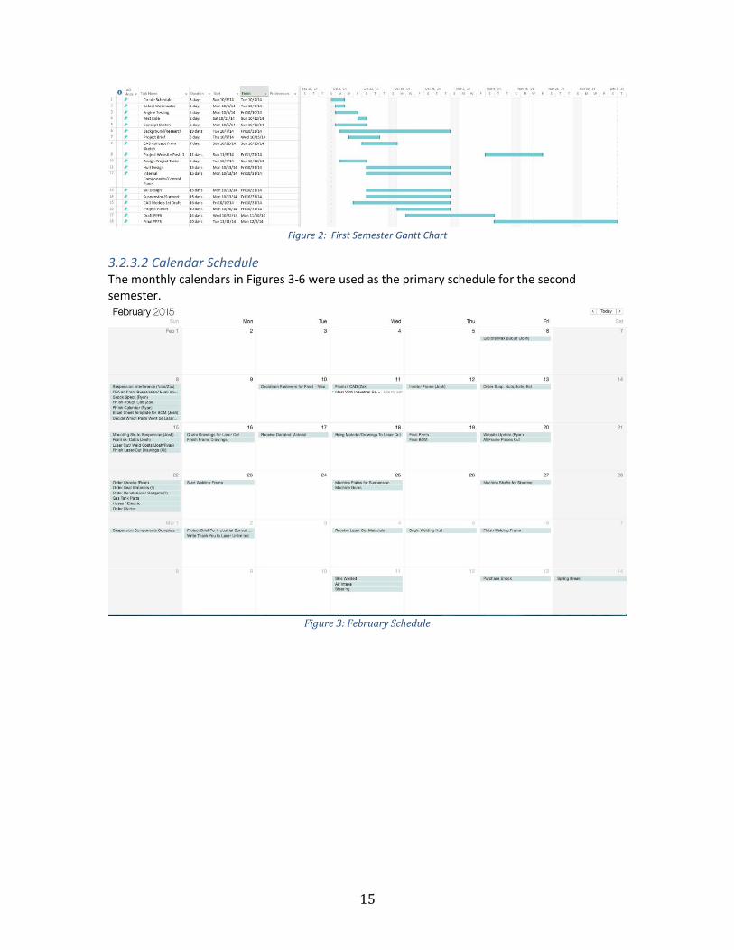
15
Figure 2: First Semester Gantt Chart
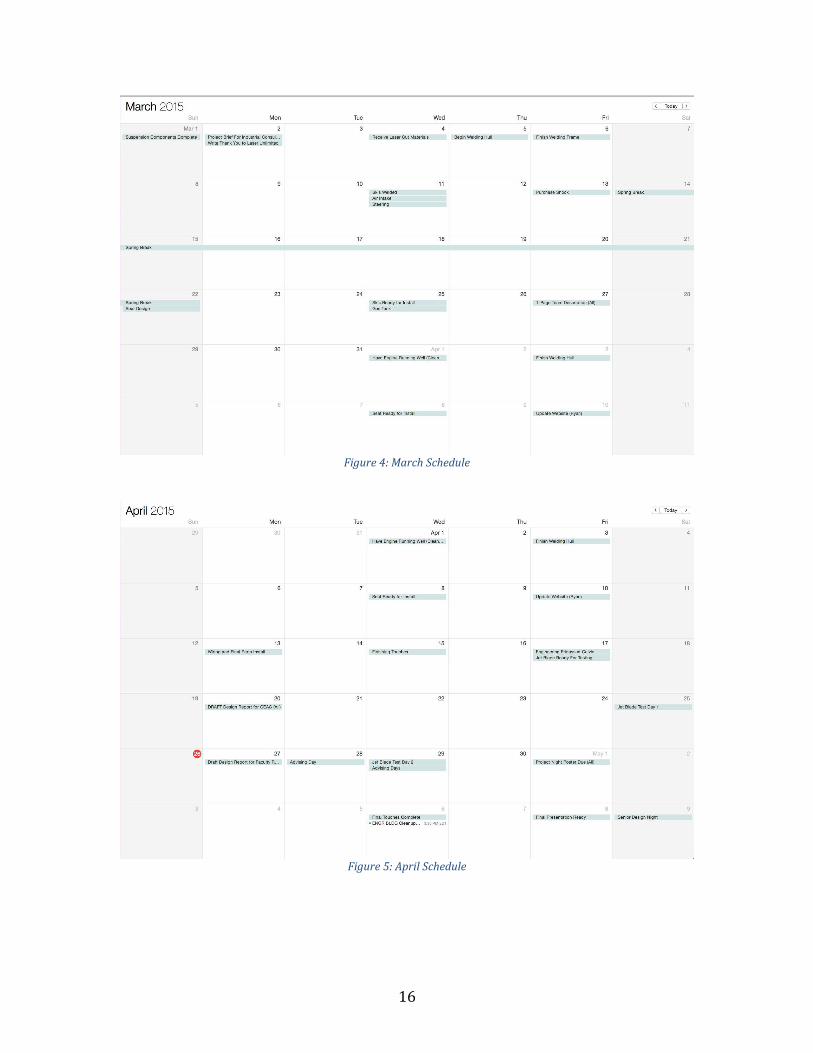
3.2.3.2 Calendar Schedule The monthly calendars in Figures 3-6 were used as the primary schedule for the second semester.
Figure 3: February Schedule
16
Figure 4: March Schedule
Figure 5: April Schedule

17
Figure 6: May Schedule
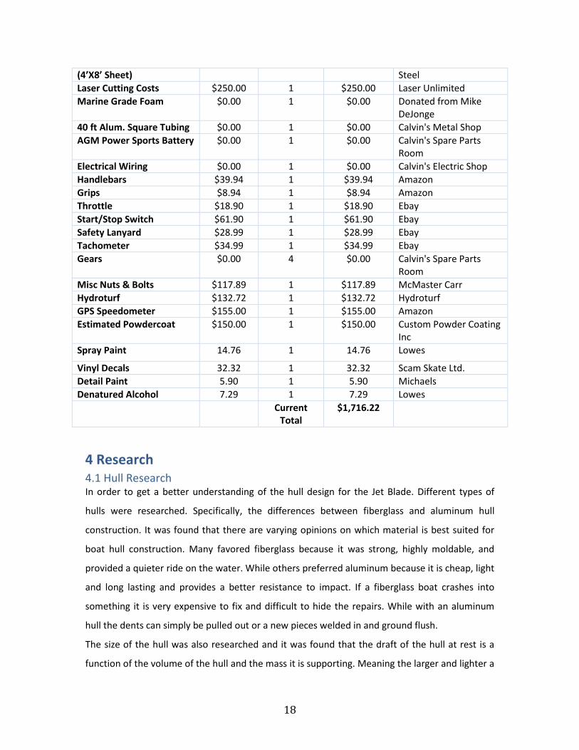
3.3 Budget Table 2, which may be seen below, shows the overall cost to build a prototype Jet Blade. The
team started with a budget of $1,000 and was able to build a working prototype, but decided to
implement additional gauges, Hydroturf foam for the foot wells, a safety lanyard, and have the
body and skis powder coated. The team’s advisor was consulted first before purchases were
made. Although the team could have assembled a prototype with the given budget it was
decided that it would be more user friendly and aesthetically pleasing to purchase the additional
items. The team had an overall budget spreadsheet which was updated whenever purchases
were made.
Table 2: Prototype Cost Breakdown
Item Cost Quantity Subtotal Vendor
Wet Bike $225.00 1 $225.00 Ebay
Spindles $20.00 2 $39.99 Ebay
Fox Float RP23 $123.99 1 $123.99 Ebay
Fox Float RP23 $160.00 1 $160.00 Ebay
Marine Gas Cap $38.40 1 $38.40 Ebay
Marine Fuel Gauge and Sending Unit
$48.95 1 $48.95 Ebay
Gas Tank Check Valve $22.20 1 $22.20 Ebay
1/8 Aluminum Sheeting $0.00 4 $0.00 Donated from Harbor
18
(4’X8’ Sheet) Steel
Laser Cutting Costs $250.00 1 $250.00 Laser Unlimited
Marine Grade Foam $0.00 1 $0.00 Donated from Mike DeJonge
40 ft Alum. Square Tubing $0.00 1 $0.00 Calvin's Metal Shop
AGM Power Sports Battery $0.00 1 $0.00 Calvin's Spare Parts Room
Electrical Wiring $0.00 1 $0.00 Calvin's Electric Shop
Handlebars $39.94 1 $39.94 Amazon
Grips $8.94 1 $8.94 Amazon
Throttle $18.90 1 $18.90 Ebay
Start/Stop Switch $61.90 1 $61.90 Ebay
Safety Lanyard $28.99 1 $28.99 Ebay
Tachometer $34.99 1 $34.99 Ebay
Gears $0.00 4 $0.00 Calvin's Spare Parts Room
Misc Nuts & Bolts $117.89 1 $117.89 McMaster Carr
Hydroturf $132.72 1 $132.72 Hydroturf
GPS Speedometer $155.00 1 $155.00 Amazon
Estimated Powdercoat $150.00 1 $150.00 Custom Powder Coating Inc
Spray Paint 14.76 1 14.76 Lowes
Vinyl Decals 32.32 1 32.32 Scam Skate Ltd.
Detail Paint 5.90 1 5.90 Michaels
Denatured Alcohol 7.29 1 7.29 Lowes
Current Total
$1,716.22
4 Research 4.1 Hull Research In order to get a better understanding of the hull design for the Jet Blade. Different types of
hulls were researched. Specifically, the differences between fiberglass and aluminum hull
construction. It was found that there are varying opinions on which material is best suited for
boat hull construction. Many favored fiberglass because it was strong, highly moldable, and
provided a quieter ride on the water. While others preferred aluminum because it is cheap, light
and long lasting and provides a better resistance to impact. If a fiberglass boat crashes into
something it is very expensive to fix and difficult to hide the repairs. While with an aluminum
hull the dents can simply be pulled out or a new pieces welded in and ground flush.
The size of the hull was also researched and it was found that the draft of the hull at rest is a
function of the volume of the hull and the mass it is supporting. Meaning the larger and lighter a

19
boat is, the shallower water it can float in. While the Jet Blade will have a lot going on under the
water line, it is still important to consider the overall draft of the Jet Blade, weighted and un-
weighted.
4.2 Ski Research Since Jet Blade's use of skis is unique to most other watercraft it was difficult to find material to
research ski design. The 1979 WetBike is the only other watercraft that hydroplanes on the
water while implementing skis. This made it a great candidate for investigation and it was
studied in order to perceive possible design issues.
Figure 7: WetBike Schematic [1]
The ability of the ski's to provide lift and raise the Jet Blade up and on top of the water was
crucial. In order to better understand the physics involved with ski's creating lift, research was
done into water skiing, snow skiing and finally boat planing. It was found that the physics
involved with a boat planing on top of the water were most similar to the physics involved in the
ski design of the Jet Blade. Daniel Savitsky performed in depth research into the physics that are
involved in the planing of boats. Through this research he developed equation for the forces
involved for the planing of flat bottomed boats, as well as boats with V - shaped hulls. A
simplified model of the physics involved can be seen in Figure 3: Pressure Distribution of a Flat
Planing Surface.

20
Figure 8: Pressure Distribution of a Flat Planing Surface [2]
Savitsky used his theory to develop equations that can be used to calculate power requirements
for various shapes and sizes of boats, as well as hull design and shape. He was also able to
incorporate trim angle (tilting angle) as well as the effects of rudders, trim tabs, and drive shafts.
It is the combination between trim angle, surface area, and shape that were most relevant to
the design of the Jet Blade.
4.3 Tilt Suspension Research It was important for the suspension system of Jet Blade to be able to tilt. Tilting suspension
systems were researched in order to develop an understanding for the kinematics involved. The
initial system that was studied was Swayspension, which was a senior design project from Calvin
College's class of 2013. This report provided the basic kinematic system that was used for the
design of the Jet Blades suspension. However, the Swayspension design incorporated a passive
tilting suspension system as seen in the figure below.

21
Figure 9: Model of Swayspension [3]
Passive means that the tilting motion of the vehicle was a function of the inertia generated from
cornering. While this suspension system was effective for Swayspension, it cannot be practically
applied to Jet Blade. The suspension design of Swayspension was a complicated design that
involved a primary and a secondary suspension system. This level of complexity was not
required for a PWC suspension system.
Tilting Motor Works was another suspensions system that was researched. This tilting
suspension design is similar to the tilting suspension that is being designed for Jet Blade. This
design can be referenced in the figure below.
Figure 10: Tilting Motor Works [4]
While the initial geometry design for the suspension was based upon Swayspension. The shock
absorber configuration of the Tilting Motor Works design inspired the design for Jet Blades
suspension system. The Tilting Motor Works design and the Swayspension design are both
passive tilt suspension systems. This means that there is no user input that mechanically
22
controls the tilting of the wheels. The Tilting Motor Works system works because the gyroscopic
effects of spinning wheels assist in the righting of the vehicle. However, this effect is lost when
the skis are substituted for wheels. Therefore, a mechanical input will be necessary in order for
Jet Blade to right itself after a lean has been initiated.
From the research that was performed, a system that incorporates an active tilting mechanism
was not found. All tilting systems are initiated by the rider shifting their weight and the
gyroscopic effects of the turning wheels, or straightening of the wheels. Therefore, an original
Active Tilt suspension system was designed for Jet Blade, while the basic geometries of the
system were based on previous designs, the mechanism that actively controls the roll of the Jet
Blade has never been implemented to the knowledge of the team.
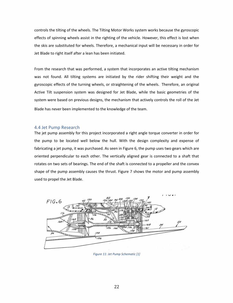
4.4 Jet Pump Research The jet pump assembly for this project incorporated a right angle torque converter in order for
the pump to be located well below the hull. With the design complexity and expense of
fabricating a jet pump, it was purchased. As seen in Figure 6, the pump uses two gears which are
oriented perpendicular to each other. The vertically aligned gear is connected to a shaft that
rotates on two sets of bearings. The end of the shaft is connected to a propeller and the convex
shape of the pump assembly causes the thrust. Figure 7 shows the motor and pump assembly
used to propel the Jet Blade.
Figure 11: Jet Pump Schematic [1]

23
Figure 12: Motor and Pump Assembly
4.5 Motor Research The motor used for the Jet Blade is a 50 HP Suzuki two stroke from a 1979 WetBike. As shown in
the figure above, the WetBike motor and pump assembly was used because of the compact
design and integration.
5 Design Process 5.1 Design Alternatives
5.1.1 Hull Material selection was the main source of design alternatives for the hull of the Jet
Blade. Fiberglass is by far the most popular hull material in the personal watercraft
industry. While it is durable and strong, it is also quite heavy and proper fabrication can be
difficult and expensive. A second material option is steel. Due its weight and rusting
characteristics, it is clear that steel is not ideal for aquatic operating conditions. A third material
alternative was aluminum. Aluminum has a higher strength to weight ratio than fiberglass and
does not corrode like steel.
5.1.2 Skis There are two different ski configurations that were considered for the Jet Blade. The first
alternative was a two-ski design which incorporated a single ski in the front and rear. An
24
advantage to this design is the gained agility by having a single ski in the front when turning.
This design would imitate the motion of riding a motorcycle. The second option considered two
skis in the front and a single at the rear. This configuration enhances the stability of craft while
maintaining agility.
5.1.3 Suspension and Steering There were a variety of different suspension systems that were considered for the connection of
the front skis to the hull of the Jet Blade.
Alternative 1: Rigid connection
A typical watercraft or PWC does not incorporate any type of a suspension system. However,
some high-end PWCs do incorporate suspension systems, yet this is very rare. The rigid
connection would be the simplest method of connecting the front skis to the hull. This option
would also be the lightest and cheapest, but it would provide the worst performance. With a
rigid suspension system the Jet Blade would lose handling capabilities. It would be difficult to go
around a corner without flipping over or an excessive amount of counterbalance would be
demanded from the rider. The rigid suspension system will also cause a very rough ride when
the water is choppy. There is also a risk that if the water is too choppy that the skis would
plunge through a wave if they are not allowed to deflect with respect to the hull.
Alternative 2: Double Wishbone
The double wishbone suspension design would allow for the deflection of the skis when rough
water is encountered. This would give the Jet Blade a smoother ride over rough water and
would also reduce the smack of the ski's landing on the water after a jump. The double
wishbone suspension would also allow the skis to deflect and reduce the possibility of the skis
getting pushed down under the water. However, the double wish bone design is limited in its
ability to provide acceptable handling performance. The double wish bone design has the same
shortcomings as a ridged connection. The Jet Blade would be likely to tip over when cornering,
or the rider would have to aggressively counterbalance the Jet Blade around a corner. With the
goal of the Jet Blade to be a user-friendly vehicle that provides an unparalleled experience on
the water, the double wish bone suspension did not fulfill all of the requirements needed to
accomplish the goal.

25
Alternative 3: Tilting Suspension System
A titling suspension system was the third type of suspension analyzed for the Jet Blade design.
This type of suspension incorporates the double wishbone suspension system but also allows
the Jet Blade to tilt as it corners. The incorporation of the double wishbone suspension will
allow the skis to deflect as they encounter rough water. This will provide a smoother ride.
However, the tiling motion will allow the Jet Blade to lean into the corner; lowering the center
of gravity and reduce the amount of counterbalance required by the rider. This also increases
the maneuverability of the Jet Blade at higher speeds, by tilting as it turns both of the front skis
are be able to maintain a greater surface area of contact. By increasing the surface area of
contact of the front skis the Jet Blade is able to plane and turn at lower speeds and feels more
responsive at higher speeds. However, the tilting suspension system is the most expensive and
complicated design of the three alternatives. Yet, it is the only alternative to provide a
comfortable ride, maneuverability and performance that is desired.
5.1.4 Propulsion
When it comes to propulsion, there are two main alternatives used by watercraft. This first is a
common propeller. Propellers are the standard for boats of all sizes and have been used for
many years. The other propulsion option is a jet pump. Jet pumps use an impeller to force
water through a nozzle to achieve thrust. Jet pumps are the standard for PWCs and are safer for
users in the water due to their enclosed nature.
5.2 Design Decisions
5.2.1 Hull Aluminum was selected as the material of choice for the hull of the Jet Blade. Aluminum
provides superior corrosion resistance to steel. It is lighter than fiberglass and steel. There is not
a large difference in price between steel and aluminum, but aluminum is significantly cheaper
than fiberglass. While fiberglass provides greater flexibility in the shape of the hull, the
manufacturing of the hull will be much easier if aluminum is used instead of fiberglass.
Therefore, aluminum was selected as the material for the hull because it is cheap, light, and
easy to work with. The initial design of the hull only included an 1/8" aluminum sheeting shell
that would be connected to the engine and pump. After doing FEA on the bottom panel that
connected to the engine and pump, the weight of the Jet Blade and rider alone gave a stress

26
that was higher than the yield strength of 3003 aluminum. A second design that included an
interior frame was needed to help distribute the load of the rider and the Jet Blade. In order to
allow access into the interior of the Jet Blade it was decided that a removable seat would be
required.
5.2.2 Skis It was decided that the Jet Blade would implement three skis in its design, with two skis in the
front and one ski in the back. The alternative design would be to implement a two ski design,
with one ski in the front and one ski in the back. The three ski design was decided upon because
it would increase the maneuverability of the PWC. With two skis located in the front it would
then allow for two edges to be in contact with the water while turning at all times giving more
control over a one ski design. Having two skis on the Jet Blade will allow for increased stability
and allow for easier use for the end user.
5.2.3 Suspension and Steering An Active Tilt suspension system was chosen for the Jet Blade because it provides the best
combination of stability, maneuverability, and comfort. The Active Tilt steering and suspension
design will feature a suspension system that is able to tilt +/- 25o from vertical. The tilting
motion of the Jet Blade is controlled by handle bar position. This means that the farther the
handlebars are turned, the further the Jet Blade will tilt. This active system was incorporated
due to the lack of gyroscopic effects cause by the rotational inertia of tires. The Active
Tilt suspension system also incorporates two shock absorbers that are connected to a double
wishbone suspension system. This will allow for the ski deflection and provide a smoother more
consistent ride. The steering system is comprised of a standard ball joint and tie rod design that
is used on most popular snowmobiles.
5.2.4 Propulsion The propulsion system used by the Wet Bike was chosen for the Jet Blade for several
reasons. First, at 50 HP, the motor will provide ample power to propel the craft and was built
for use in marine applications. Second, the integrated right angle gearbox is necessary in order
to achieve the required motor and pump arrangement. The downward facing intake on the jet
pump is ideal as it allows the proper flow of water while the skis are on plane.
27
5.2.5 Control system Basic engine start and stop controls similar to other PWCs are used on the Jet Blade. In
addition, an electronic choke has been implemented along with a kill switch lanyard for
safety. A thumb throttle is used to allow better control while maneuvering.
5.3 Design
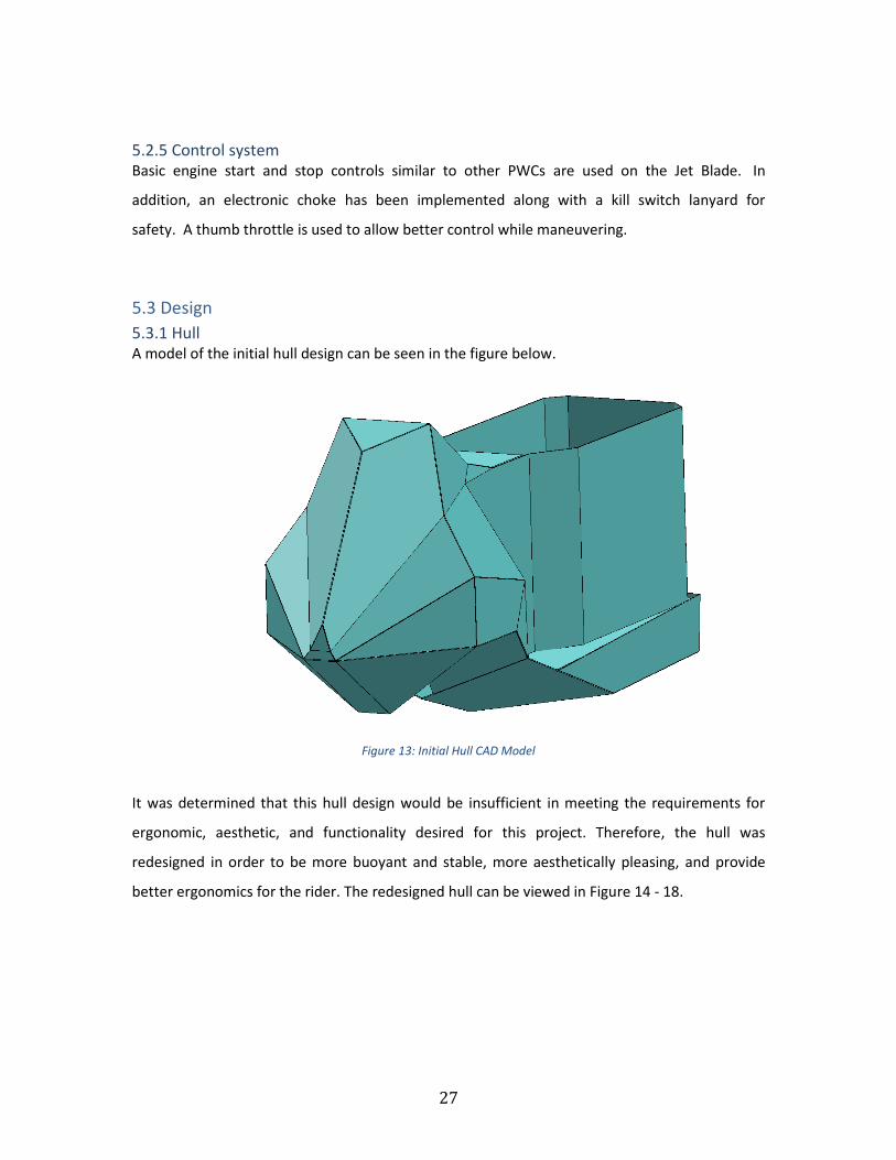
5.3.1 Hull A model of the initial hull design can be seen in the figure below.
Figure 13: Initial Hull CAD Model
It was determined that this hull design would be insufficient in meeting the requirements for
ergonomic, aesthetic, and functionality desired for this project. Therefore, the hull was
redesigned in order to be more buoyant and stable, more aesthetically pleasing, and provide
better ergonomics for the rider. The redesigned hull can be viewed in Figure 14 - 18.
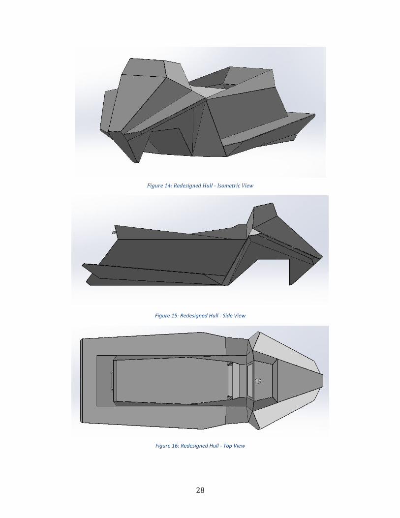
28
Figure 14: Redesigned Hull - Isometric View
Figure 15: Redesigned Hull - Side View
Figure 16: Redesigned Hull - Top View

29
Figure 17: Redesigned Hull - Rear View
Figure 18: Redesigned Hull - Front View
This hull was designed from 1/8" aluminum sheeting. It was fully welded together in order to
provide a strong and water tight hull. In order to distribute the load of a rider and the Jet Blade
an interior frame is necessary to reduce the stress on the bottom plate. Figure 19 shows the
frame integrated into the hull. The pump and engine mount between the bottom panel of the
hull and seal with a rubber gasket that was used on the purchased WetBike. The gasket has a
0.59” spacing between the engine and pump assembly which sealed between the original Wet
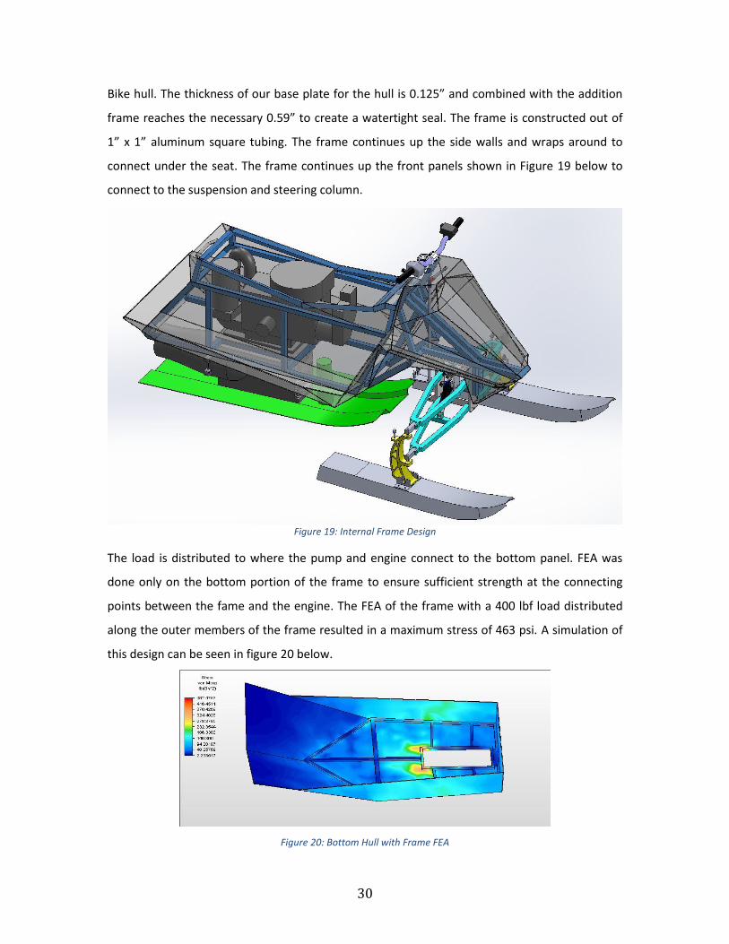
30
Bike hull. The thickness of our base plate for the hull is 0.125” and combined with the addition
frame reaches the necessary 0.59” to create a watertight seal. The frame is constructed out of
1” x 1” aluminum square tubing. The frame continues up the side walls and wraps around to
connect under the seat. The frame continues up the front panels shown in Figure 19 below to
connect to the suspension and steering column.
Figure 19: Internal Frame Design
The load is distributed to where the pump and engine connect to the bottom panel. FEA was
done only on the bottom portion of the frame to ensure sufficient strength at the connecting
points between the fame and the engine. The FEA of the frame with a 400 lbf load distributed
along the outer members of the frame resulted in a maximum stress of 463 psi. A simulation of
this design can be seen in figure 20 below.
Figure 20: Bottom Hull with Frame FEA

31
By updating the design of the hull the overall length was increased by 6.5” from the original
design bringing the total length to 84” long. The width grew by 6.3” making the Jet Blade 34”
wide. Whereas the height dropped by 7.2” bringing the total height of the hull to 28”. By making
these dimensional changes the Jet Blade hull now has a lower center of gravity and a wider foot
print. This will help keep the Jet Blade upright and balanced when it is floating in the water. By
increasing the width, extra space was added around the engine area to allow better access to
work on the engine, adjust the battery or inspect the gas tank. This extra width also increased
the volume of the hull and increased the buoyant force of the hull.
The redesigned hull also provided better ergonomics for the rider. The seat was raised to allow
the legs to straighten. This places the rider in a forward position and allows for better body
control as well as increased agility. The foot wells were also pushed farther forward to allow the
feet to be placed almost underneath the handle bars. By allowing the feet to move farther
forwards the rider will be more comfortable when standing as they can stand up straighter and
do not have to hunch over. On the rear end of the Jet Blade a ledge was added to connect the
foot wells. This assists the rider when they are trying to board the Jet Blade. The ledge provides
a place to locate the rider’s legs or knees when they are climbing aboard the water craft.
A removable seat was designed to allow easy access to the interior of the craft. The seat
comprised of 1/8” aluminum to provide the strength and shape required to align with the main
hull. A 1” piece of Baltic Birch was used as a base for marine grade foam to be placed on. Marine
grade vinyl was wrapped around the foam and stapled to the Baltic Birch base. Rubber gasket
lines the perimeter of the seat where it comes into contact with the body of the craft to seal any
water that might enter.
The buoyancy force needed to keep a craft afloat is equal to the weight of the craft. The volume
of water displaced by the Jet Blade changes with its profile. The volume of water displaced for
three conditions were calculated. These calculations were done using a solid model of the Jet
Blade and taking cross sectional cuts and determining the volume of the solid body. This was
then used to determine the floating height which is measured in inches from the bottom of the
hull to the water level. The calculations for the buoyancy force are in Appendix B. The
calculations and figures below include the wet weight of the Jet Blade which includes a full gas

32
tank. Figure 17 shows where the Jet Blade sits at rest relative to the waterline with no rider.
With no rider the jet blade sits 9.91 inches into the water relative to the bottom panel. With the
assumed 200 lb. rider the Jet Blade sits 14.41 inches into the water. The maximum rider capacity
was determined at the point when the bottom of the seat was level with the water. The
maximum rider capacity was calculated to be 410 lbs.
Figure 21: Float Height without Rider
Figure 22: Float Height with 200 lb. Rider

33
Figure 23: Float Height with 410 lb. Rider
The addition of the frame attached to the outer hull is critical to the strength of the hull design.
With FEA the bottom hull has been proven to withstand the weight of the Jet Blade and rider
with a high safety factor. The buoyancy calculations show the feasibility of the current design
and it will be able to float at rest with a 200 lb. rider and a maximum capacity of 410 lbs.
5.3.2 Skis It was important that air did not become entrapped in the water which then reaches the pump
assembly. If entrapped air reaches the pump it causes a significant decrease in efficiency and
performance. Since the front of the Jet Blade rides on two skis the turbulence created from the
skis will be on either side of the back ski and therefore not be a factor on introducing entrapped
air into the pump. The design of the skis accommodates for maneuverability, while still
maintaining a smooth ride when operating in a straight line. The skis have enough bottom
surface area to ensure the Jet Blade is able to plane on top of the water. The front skis have
been specifically designed in conjunction with the Active Tilt suspension employed on the Jet
Blade. Computer models of the skis may be seen in the below figures. The front skis features a
design with ribs coming down on either side in order to achieve the cutting action desired. The
angle at which these ribs came down at in relation to horizontal section of the ski was calculated
to be 120 degrees. This angle was chosen so that when the Active Tilt suspension is leaned to
the left or right the rib of the ski maintains an angle on the surface of the water. This ensures
that the ribs are not positioned perpendicular to the surface of the water. If this were to occur
the lift generated by the skis would significantly decrease.

34
Figure 24: Front Ski CAD Model
Figure 25: Rear Ski CAD Model
In order to prove the feasibility of the ski design planing calculations were completed to make
sure that the skis would indeed rise out of the water and plane on the surface. Savitsky’s planing
equations were used in order to determine the correct ski design. A program was located that
incorporated the parameters required for Savitsky’s equations and produced a graphical
representations of the ski’s performance. These equations were created for boat hulls and not
skis, so some assumptions have to be made. First, was that the ski could be modeled as the hull
of a flat bottomed boat. Second, was that the center of gravity for the entire Jet Blade was also
the center of mass for the same flat bottomed boat. The weight of a 250 lb. rider was also
included. This essentially modeled the Jet Blade as a tall front heavy boat with a small hull as its
foot print. The parameters shown in Table 3 were then inserted into the program and Figure 15
was generated.

35
Figure 26: Definition of Inputs [5]
Table 3: Input Values
Variable Value Units Displacement 272 kg Longitudinal Distance of Center of Gravity from Transom
0.95 m
Vertical Distance From Center of Gravity to Transom
0.61 m
Beam of Hull 0.63 m Angle of Dead Rise 0 (Flat Bottomed Hull) Degrees Distance Offset from Center of Gravity
0.46 m

36
Figure 27: Results of Savitsky Procedures
During this analysis it was determined that the initial beam (b) or width of the ski was not wide
enough. The analysis shows that a minimum ski width of .63 meters or 2’ 3/4" is necessary for
the Jet Blade to work properly. With this design the Jet Blade is able to get up and on plane with
the given design and available power. From the graph it can be seen that at very low speeds the
angle that is required for the Jet Blade to get on plane is approximately 20o. Figure 16 provides a
model of Jet Blade at 20o to the horizontal plane. This image was compared Figure 17 which is a
photo of the Wet Bike during its planing process and the images.
Figure 28: Jet Blade During Planing Process
Figure 29: WetBike During Planing Process
Interestingly, these images show that the designed angle of attack is very similar to the actual
angle of attack that was demonstrated. This again reinforces the feasibility of the design. The
design of the front skis was not incorporated into the planing process. This was done to simplify
the modeling as well as to insure the design of the rear ski was robust enough to provide
sufficient lift for the entire Jet Blade. The addition of the front ski’s and the hull will only add to
the lift force that is generated and will help to get the Jet Blade onto plane even faster. It is also
37
crucial in for the skis to be strong enough in order to handle the required forces that they will be
subjected to. An FEA analysis was done to verify that the skis would be strong enough in which
the forces applied, the displacement, and resulting stresses may be seen in Appendix C.
5.3.3 Suspension and Steering
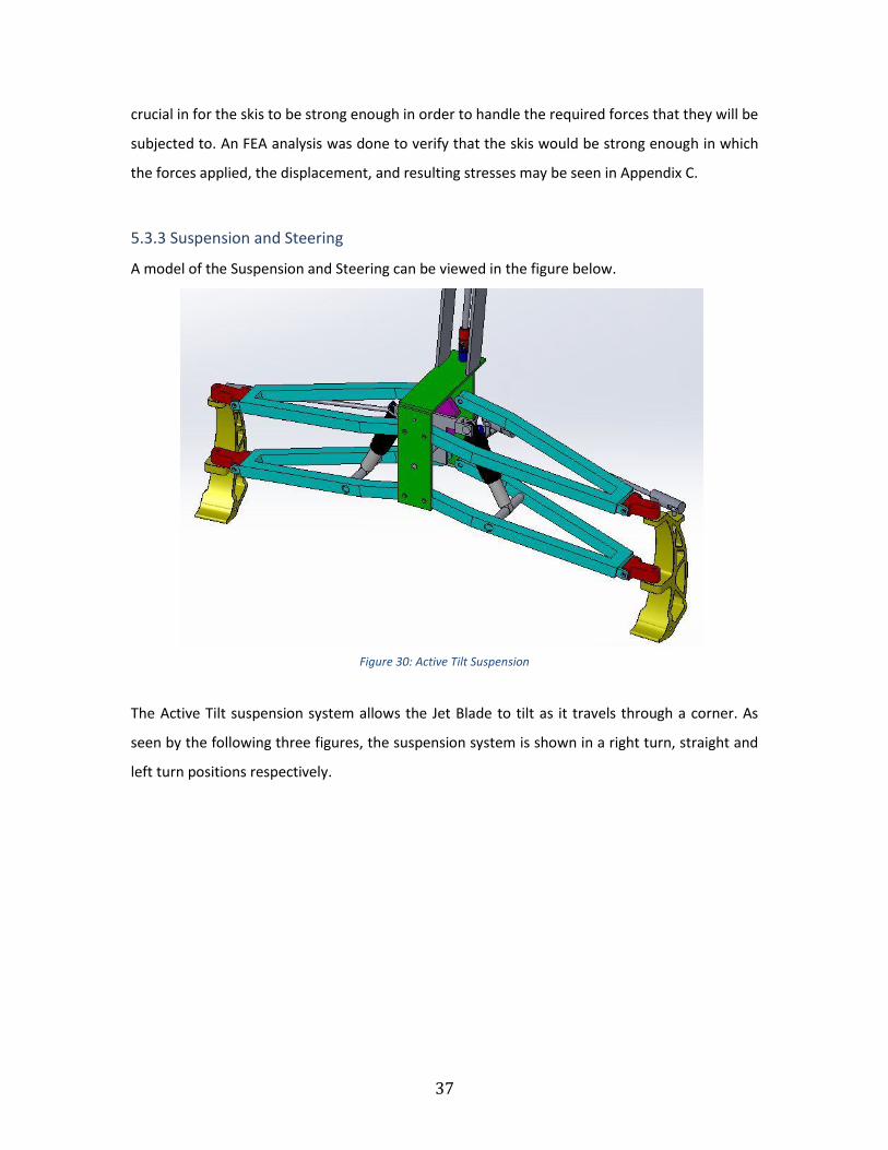
A model of the Suspension and Steering can be viewed in the figure below.
Figure 30: Active Tilt Suspension
The Active Tilt suspension system allows the Jet Blade to tilt as it travels through a corner. As
seen by the following three figures, the suspension system is shown in a right turn, straight and
left turn positions respectively.

38
Figure 31: Active Tilt - Right Turn
Figure 32: Active Tilt – Straight
Figure 33: Active Tilt - Left Turn

39
This suspension design is made from aluminum with every rotating axis being connected with
shoulder bolt connections. This will provide the degrees of freedom necessary for the active tilt
suspension system to function properly. It is necessary that the tilting motion be uniform and
smooth. Another feature of the Active Tilt Suspension system that will aid in rider comfort is the
pneumatic shock absorbers that are integrated into the double wishbone suspension design as
seen in the following figure. When the suspension is fully compressed it provides Jet Blade with
8" of travel of the front skis. This will allow for comfortable traverse over rough water.
Figure 34: Compressed Suspension
To verify the feasibility of this design, several major components were analyzed using FEA.
Figures showing force loading, resultant stress, and displacement can be found in Appendix C.
In each case, maximum experienced stress was well below the material yield stress of 40 ksi.
Position and torque calculations were done in order to prove the feasibility of the designs, these
calculations can be viewed in Appendix B. In order to determine the position of the handle bars
at full suspension tilt a set of kinematic position equations was derived, from this it was
determined that a miter gear set and a spur and pinion gear set could be used. This also
determined that a 1:1 gear ratio for both gear sets was the optimal gear ratio. This provided a
1:1 overall ratio between the turning of the handle bars and the tilting of the Jet Blade. While
this was optimal for the tilting aspect of the design, it raised some issues with the amount of
force required to right the craft after a turn. Different options were explored such as spring
assisted tilt correction and revision of mathematical models to ensure proper moment
balancing. This would reduce the amount of torque that is required by the operator during
turning. It is important that the steering of the Jet Blade be light and responsive so as to reduce
rider fatigue and maintain a pleasurable riding experience.

40
The initial design for the steering connection involved the use of a universal joint. This would
allow the steering shaft to be tilted back 15o and allow the steering stem to exit perpendicular to
the control panel. This design was aesthetically pleasing and ergonomically comfortable.
Unfortunately, the universal joint that was being used introduced to much slop into the steering
system. This coupled with the backlash in the gears as well as sloppy set screw connections
resulted in a very unresponsive steering system. The handle bars could be rotated over half of a
turn before a response was seen in the Active Tilting suspension or the turning of the skis. Due
to this it was very difficult to ride the Jet Blade. In order to address this issue the universal joint
was removed from the steering system and the steering shaft now rises vertically out of the
control panel. This does not greatly affect the ergonomics, however it does have minor aesthetic
influence. This was deemed acceptable due to the tremendous gains in strength and steering
precision.
In order to reduce the slop that was introduced by the slipping of the set screws on the shafts,
roll pins were used to securely fasten the gears to the shafts. By using a roll pin connection the
precision of the steering and tiling linkages was greatly improved. However, the use of roll pins
removes the ability to perform and fine tune alignment in the steering system. Once the pins
were placed, it was crucial that the steering system was properly aligned.
Another change to the steering system was the addition of a support frame work for the steer
shaft. This was constructed from one inch square tubing and a flange bearing. The flange
bearing allowed a precise fit around the steering shaft while providing a smooth and secure
reinforcement to the handlebars. This reinforcement was necessary as the handlebars are the
main point of interaction between the rider and machine and is a big factor in determining the
ride quality of the Jet Blade.
These changes to the steering and suspension system have greatly improved the ride quality of
the Jet Blade. It is more stable and easier to ride for a beginner. However, there is still room for
improvement and a variety of options will continue to be pursued in order to improve the
steering system.
5.3.4 Propulsion
As shown in Figures 6 and 7, the propulsion system used in the Jet Blade is a bottom intake jet

41
pump. The bottom intake and integrated right angle gearbox allow for maintained performance
and proper motor and pump configuration. Shown in Figure 7, the motor used in the Jet Blade is
a two stroke, water-cooled, Suzuki that produces 50 HP. This motor is ideal because of its
compact integration with the jet pump. Figure 15: Results of Savitsky Procedures indicates that
50 HP will be ample power to achieve planing.
5.3.5 Complete Design
Figure 35: Complete CAD Model

42
Figure 36: Complete Model – Front View
Figure 37: Complete Model – Right Turn
43
Figure 38: Complete Model – Left Turn
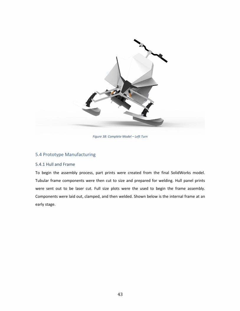
5.4 Prototype Manufacturing
5.4.1 Hull and Frame
To begin the assembly process, part prints were created from the final SolidWorks model.
Tubular frame components were then cut to size and prepared for welding. Hull panel prints
were sent out to be laser cut. Full size plots were the used to begin the frame assembly.
Components were laid out, clamped, and then welded. Shown below is the internal frame at an
early stage.

44
Figure 39: Internal Frame
Once the hull panels returned from the laser cutter, they were used to accurately fabricate the
remaining internal frame. Because of the accuracy of the cut panels, a proper fit could only be
achieved with proper panel placement. The figure below shows the frame and panels part way
through the assembly process.
Figure 40: Hull and Frame Mock Up
The front hull was assembled using tape to hold the panels in place for tacking. Once fully
tacked, the seams were welded. Once the bottom section of the hull was welded, an initial float
test was conducted to insure water-tight welds before sealing off the foot wells. The figure
below shows the test in progress.

45
Figure 41: Initial Float Test
After passing the initial float test, the foot wells were capped and the rest of the hull was
welded. The complete hull assembly can be seen below.
Figure 42: Complete Hull Assembly
The seat for the Jet Blade was shaped out of marine grade foam and wrapped in vinyl designed
for marine environments. The support frame was made from 1/8” aluminum like the rest of the
hull and designed to create a near water tight seal.
5.4.2 Skis
Ski fabrication began with full scale plots of the required sheet metal parts. The plots were then
used to cut the required pieces of 1/8” aluminum. The top sections were then rolled to the
appropriate radius before the side walls were welded on.

46
5.4.3 Suspension and Steering
Suspension fabrication started with the A-arms. One inch square tubing was cut, bent, and
welded into the specified shape. The mounting plates were made using a mill to ensure precise
hole locations. The suspension linkage T and steering linkage joints were also made using a mill.
To allow for tuning, adjustable shock mounts and steering linkage mount were designed and
implemented. These components can be seen in the following two figures.
Figure 43: Adjustable Shock Mount
Figure 44: Adjustable Steering Linkage Mount

47
5.4.4 Final Assembly
With the individual components completed, the final assembly could begin. The engine and
pump assembly were bolted onto the hull through a large gasket that serves to seal out water
and isolate engine vibration. The suspension assembly was then bolted through the hull directly
to the internal frame. The control system was then wired including the start/stop switch,
throttle, gauges, electronic choke, and bilge pump. Finally, the skis and handle bars were
mounted to complete the prototype assembly. The complete assembly can be seen in the
following figures.
Figure 45: Completed Prototype - Front View before Paint

48
Figure 46 : Completed Prototype – Front View after Paint
Figure 47: Completed Prototype - Rear View after Paint
49
6 Testing
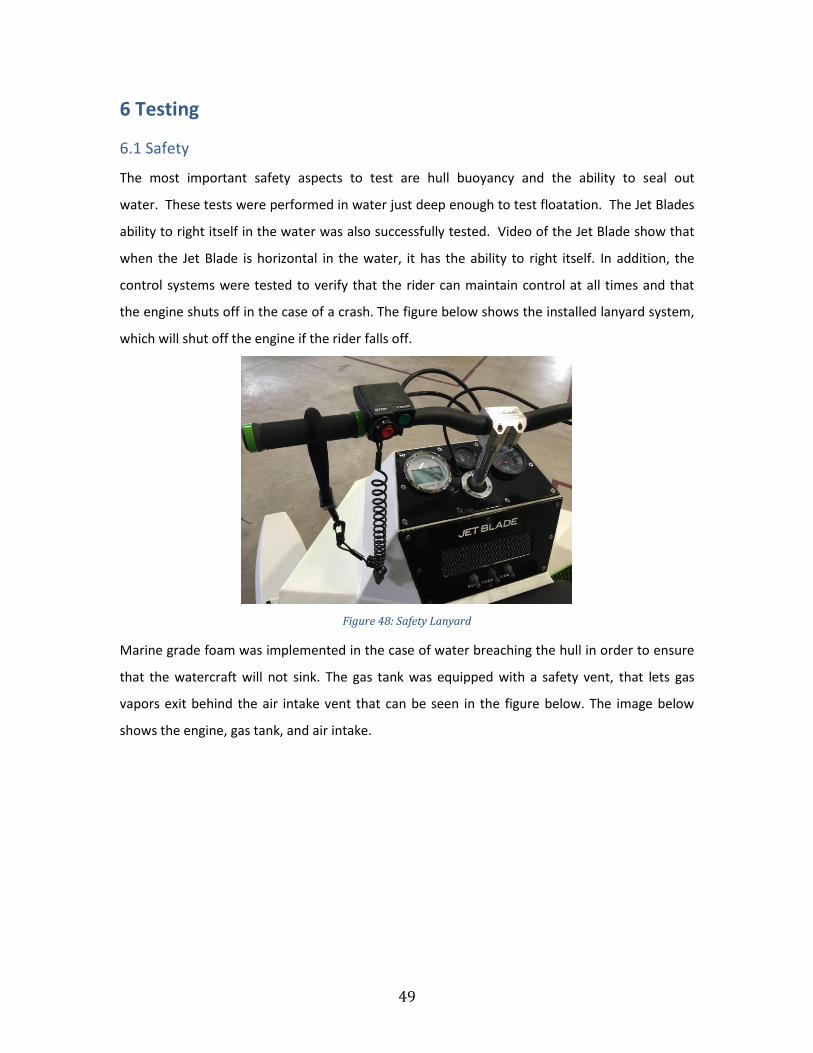
6.1 Safety
The most important safety aspects to test are hull buoyancy and the ability to seal out
water. These tests were performed in water just deep enough to test floatation. The Jet Blades
ability to right itself in the water was also successfully tested. Video of the Jet Blade show that
when the Jet Blade is horizontal in the water, it has the ability to right itself. In addition, the
control systems were tested to verify that the rider can maintain control at all times and that
the engine shuts off in the case of a crash. The figure below shows the installed lanyard system,
which will shut off the engine if the rider falls off.
Figure 48: Safety Lanyard
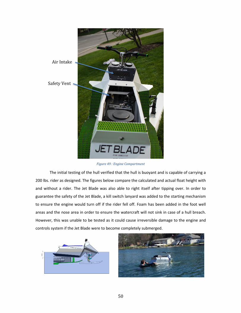
Marine grade foam was implemented in the case of water breaching the hull in order to ensure
that the watercraft will not sink. The gas tank was equipped with a safety vent, that lets gas
vapors exit behind the air intake vent that can be seen in the figure below. The image below
shows the engine, gas tank, and air intake.
50
Figure 49 : Engine Compartment
The initial testing of the hull verified that the hull is buoyant and is capable of carrying a
200 lbs. rider as designed. The figures below compare the calculated and actual float height with
and without a rider. The Jet Blade was also able to right itself after tipping over. In order to
guarantee the safety of the Jet Blade, a kill switch lanyard was added to the starting mechanism
to ensure the engine would turn off if the rider fell off. Foam has been added in the foot well
areas and the nose area in order to ensure the watercraft will not sink in case of a hull breach.
However, this was unable to be tested as it could cause irreversible damage to the engine and
controls system if the Jet Blade were to become completely submerged.
Air Intake
Safety Vent

51
Figure 50: Calculated and Actual Float Height
Figure 51: Calculated and Actual Float Height with 180 lb. Rider
6.2 Launch Capabilities The launch capabilities of the Jet Blade were unable to be tested due to shortage of time.
However with 3 to 4 people the Jet Blade is able to be carried into the water with moderate
effort.
6.3 Strength
In order to test the strength of the Jet Blade it will be jumped off of a standard boat wake. This
process, although crude, will demonstrate the strong construction of the hull, suspension and
skis. The Jet Blade should be able to withstand fifteen repeated jumps of a two foot tall wave
(largest amplitude wave in standard operating conditions).
The Jet Blade was able to pass this test with no signs of fatigue or wear. The suspension
system worked very well to absorb the waves and ride over the top of the water and not plunge
through the waves. Off some waves the Jet Blade was able to become air born and still landed
smooth with no bending or deformation of the ski’s, A-Arms or suspension components. In
some cases the suspension compressed enough to allow water to hit the hull. However, due to
the slanted angle of the underside of the foot well, the Jet Blade remained in top of the water
and functioning superbly.
6.4 Performance and Handling Due to a lack of time extensive testing was unable to be completed. This did not allow for
qualitative comparisons between the Jet Blade and other personal water craft.

52
However, Jet Blade was able to perform successfully. The largest problem was the backlash in
the steering system. This was caused by misalignment of the gears in the Active Tilt suspension
system. Due to this backlash it was difficult to balance on the Jet Blade when traveling in a
straight line. This caused difficulties during testing as the rider was constantly correcting the
steering in order to go in the desired direction. Due to this the team decided to redesign the
steering system in order to remove the backlash in the gears. The steering system has been
updated to the current design, however a water test has not been completed. Although
backlash was present in the steering the Jet Blade performed exceptionally well. Once a corner
was initiated the Jet Blade was easy to control and comfortable to ride. Also, the backlash in the
gears was only noticeable at speeds greater than approximately 20 mph below that the vehicle
remained stable and easy to control. This was due to the relative location of the rear ski in the
water. At lower speeds the ski was able to sit lower in the water and water was able to contact
the foot wells of the Jet Blade assisting the rider with balancing and lowering the center of
gravity.
Jet Blade performed exceptionally during the initial planing process. From rest the skis were
below the surface of the water. Once the rider increased the throttle the Jet Blade would lift the
front skis out of the water and ride up on top of the surface of the water just as expected. This
action happened in a fast and controlled manner.
The Jet Blade provided significant buoyancy and was exceptionally water tight. The seal
between the seat and the hull was a main concern of for leakage. This was tested by tipping the
Jet Blade on its side until the seam between the seat was submerged. This seal performed as
expected and let very little water into the hull. A bilge pump was added to the design in order to
pump out excess water. However, the water level was never high enough to successfully pump
out of the hull.
During the second phase of testing a rider who had no previous Jet Blade riding experience got a
chance to test drive the water craft. He was able to start and begin planing without issues. Once
on top of the water the rider was able to turn and maneuver the craft with minimal effort at low
speeds. At higher speeds the ride was more sporadic with sharp turns and awkward body
language. However, after several minutes of riding this went away and the test rider felt much
53
more comfortable. Cornering was easier and the rider even successfully jumped the Jet Blade.
After the first ride the rider stated that, “Its table once you’re up! Smooth. Cuts through the
water like a dolphin fin! Faster than I expected. It’s sleek, heavy, and could use rear suspension.”
In the end after testing was finished the team was very happy with the performance of the Jet
Blade. It handled as expected and with a few minor changes it was significantly easier to ride.
The Jet Blade is a fun, unique water craft that provides an unparalleled experience on the water.
7 Business Plan
7.1 Market Competition Currently there is nothing on the market that is identical to the Jet Blade. The Jet Blade is a
unique product with a target market comprised of individuals that have some discretionary
income, as it is a luxury item. Specifically individuals or those individual’s kids that have an
interest in extreme sport and have access to a body of water to ride the Jet Blade. The key
marketing strategy for the Jet Blade is to create superior customer value by means of
differentiation. Competitors to the Jet Blade would include any manufacturer of personal
watercraft vehicles. Expected major competitors may be seen below in Table 3.
Table 4: Market Competition
Personal Water Craft Base Price
Sea-Doo Spark $ 4,999.00
Yamaha Superjet 2015 $ 8,499.00
Kawasaki Jet Ski STX-15F $ 9,699.00
Yamaha FX Cruiser SVHO $ 15,499.00
Quadski $ 40,000.00
7.2 Break-Even Analysis In order to perform a break-even analysis variable and fixed costs were researched and
estimated. These costs may be seen below in Table 4. With a selling price of $12,000.00 a break-
even point of 75 units was calculated.
Table 5: Estimated Production Costs
Production Cost Component
Per Unit Total Annual
Raw Materials $ 2,375.00 $ 296,875.00

54
Direct Labor $ 2,500.00 $ 312,500.00 Variable Overhead $ 400.00 $ 50,000.00 Total Variable Manufacturing Cost
$ 5,275.00 $ 659,375.00
Annual Rent 15,000 @ $3.50/sq·ft * $ 52,500.00 Utilities 15,000 @ $2.30/sq·ft * $ 34,500.00 Insurance $ 100,000.00 Selling and Administration
$ 30,000.00
Marketing $ 20,000.00 Engineering $ 200,000.00 Total Fixed Expenses $ 437,000.00 Total Expenses $ 1,096,375.00 Selling Price $ 12,000.00 $ 1,500,000.00 Profit (Loss) $ 403,625.00 *http://www.cityfeet.com/cont/mi/grand-rapids-industrial-space#pgNum=6 *http://www.buildings.com/article-details/articleid/16749/title/utility-expenses-decrease- across-u-s.aspx
8 Conclusion
After the preliminary design decisions, calculations, and budgeting Team 6 has decided that the
project is feasible. The team has completed the task of manufacturing a completely functional
Jet Blade prototype. After initial testing and redesign the Jet Blade is able to successfully
function as a unique water craft that provides an unparalleled rider experience.
9 Acknowledgements
The team would like to acknowledge the following for their support and advice on the project.
Ned Nielsen - Team advisor and Mechanical Engineering Professor
Phil Jasperse - Metal shop instructor
Ren Tubergen - Mechanical Engineering Professor
John Sherwood – Project Photogropher
Harbor Steel & Supply Corp – Donation of aluminum sheeting
Lasers Unlimited Inc. – Cutting the body panels for Jet Blade
Custom Powder Coating – Finish coating the Jet Blade

55
10 Bibliography [1] Nelson, Tyler. Jet Powered Watercraft. Still Water Properties, assignee. Patent 3948206. 6
Apr. 1976. Print.
[2] Savitsky, Daniel : "Hydrodynamic design of planing hulls", Marine Technology, Vol. 1, No.1,
1964.
[3] http://www.calvin.edu/academic/engineering/2012-13-team15/ [4] http://thekneeslider.com/tilting-v-max-trike-by-tilting-motor-works/
[5] http://illustrations.marin.ntnu.no/hydrodynamics/resistance/planing/index.html
Appendix A: Project Gantt Chart

56

57
Appendix B: EES Calculations EES Buoyancy Calculations

58
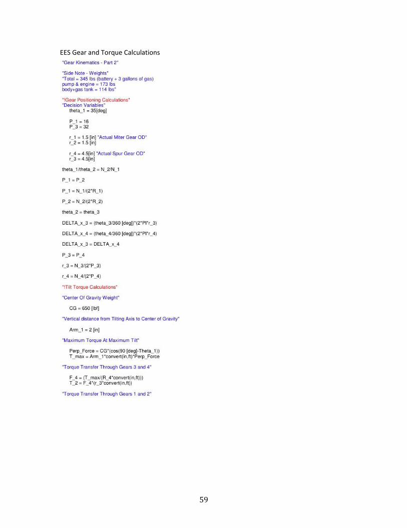
59
EES Gear and Torque Calculations

60
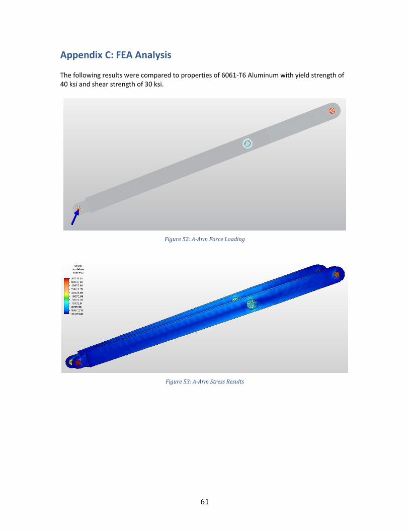
61
Appendix C: FEA Analysis The following results were compared to properties of 6061-T6 Aluminum with yield strength of 40 ksi and shear strength of 30 ksi.
Figure 52: A-Arm Force Loading
Figure 53: A-Arm Stress Results

62
Figure 54: A-Arm Displacement Results
Figure 55: Yoke Force Loading

63
Figure 56: Yoke Stress Results
Figure 57: Yoke Displacement Results
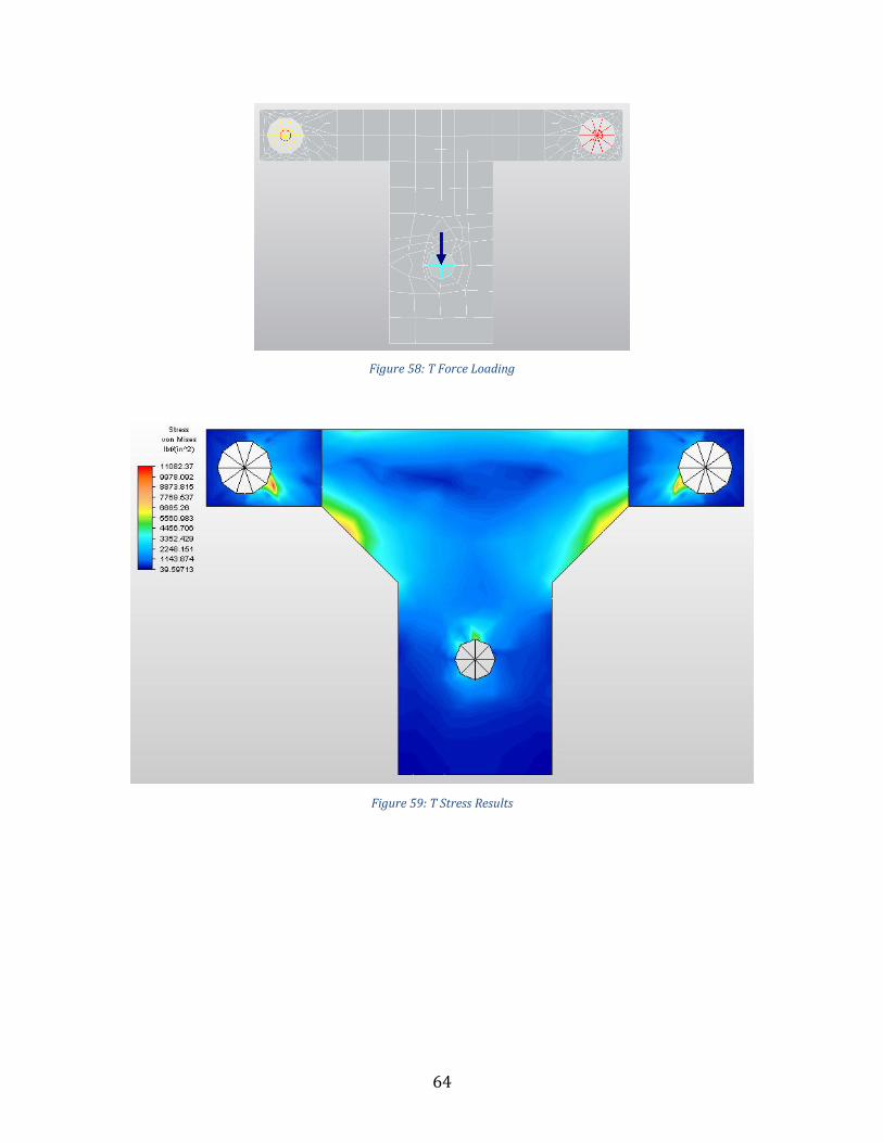
64
Figure 58: T Force Loading
Figure 59: T Stress Results

65
Figure 60: T Displacement Results
Figure 61: Front Ski Stress Results

66
Figure 62: Front Ski Displacement Results