final year project report (jet engine)
TRANSCRIPT

A PROJECT REPORT ON
DESIGN AND CONNSTRUCTION OF JET ENGINE USING
AUTOMOTIVE TURBOCHARGER
A DISSERTATION
SUBMITTED FOR THE PARTIAL FULFILLMENT OF THE REQUIREMENTS FOR THE
DEGREE OF
BACHELOR OF TECHNOLOGY
IN MECHANICAL ENGINEERING
SUBMITTED BY
FLEVIAN GONSALVES 081020116
PRAMOD PAWAR 081020143
GUIDE
PROF.H.P.KHAIRNAR
DEPARTMENT OF MECHANICAL ENGINEERING VEERMATA JIJABAI TECHNOLOGICAL INSTITUTE

MATUNGA, MUMBAI 400 019
A project report on
DESIGN AND CONNSTRUCTION OF JET ENGINE USING
AUTOMOTIVE TURBOCHARGER
A DISSERTATION
Submitted for the partial fulfillment the requirements for the degree of
BACHELOR OF TECHNOLOGY
In Mechanical Engineering
Submitted by
FLEVIAN GONSALVES 081020116
PRAMOD PAWAR 081020143
Guide
PROF.H.P.KHAIRNAR
DEPARTMENT OF MECHANICAL ENGINEERING
VEERMATA JIJABAI TECHNOLOGICAL INSTITUTE
MATUNGA, MUMBAI 400 019
CERTIFICATE OF APPROVAL
By Examiners
This is to certify that the dissertation entitled “DESIGN AND CONSTRUCTION OF JET ENGINE
USING DIESEL TRUCK TURBOCHARGER” is bonafied record of the dissertation work done by
Flevian Gonsalves 081020116
Pramod Pawar 081020143
This dissertation is approved for the BACHELOR OF TECHNOLOGY, under the guidance of Prof.
H. P. Khairnar, DEPARTMENT OF MECHANICAL ENGINEERING, V.J.T.I.
Prof. H. P. Khairnar Dr. M. A. Dharap
Project Guide Head of the Department
Mechanical Engineering Dept. Mechanical Engineering Dept.
V.J.T.I. Mumbai 400019 V.J.T.I. Mumbai 400019

CERTIFICATE OF APPROVAL
By Examiners
This is to certify that the dissertation entitled “DESIGN AND CONSTRUCTION OF
JET ENGINE USING AUTOMOTIVE TURBOCHARGER” is bonafied record of the
dissertation work done by
Flevian Gonsalves 081020116
Pramod Pawar 081020143
This dissertation is approved for the BACHELOR OF TECHNOLOGY, under the
guidance of Prof. H. P. Khairnar, DEPARTMENT OF MECHANICAL ENGINEERING,
V.J.T.I.
Signature Signature____________
Name Name_____________
Examiner Examiner
(Internal) (External)

INDEX
1. Introduction
2. Need of the study
3. Objective
Section 1: Design of Jet Engine
4. Approach towards design
5. Block diagram of the engine
6. Physical model of the engine
7. Components of the engine
8. Design and selection of the components
Section 2: Construction of Jet Engine
9. Part List
10. Construction of combustion chamber
11. Construction of exhaust nozzle
12. Assembling engine’s subsystems
13. Control panel
14. Operational and startup procedure
15. Results and conclusion
Appendices
Bibliography
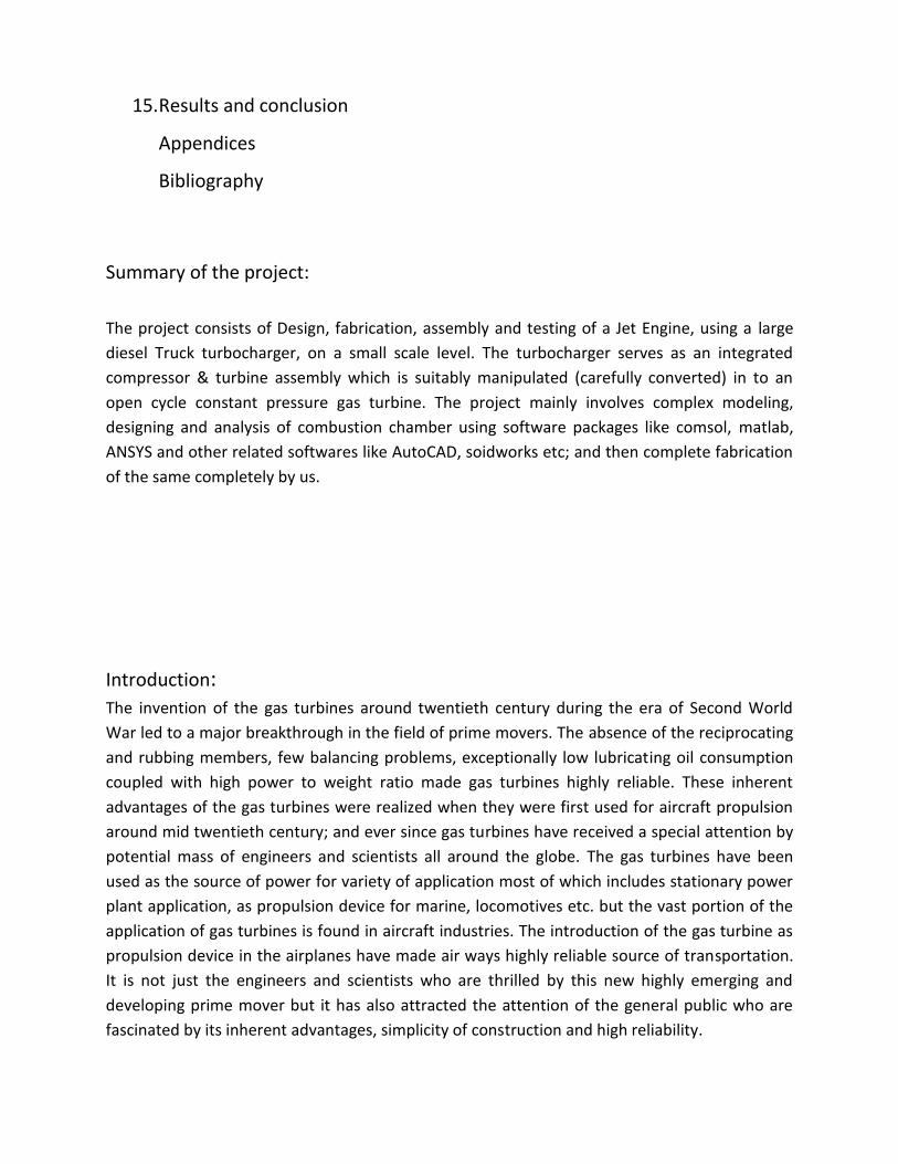
Summary of the project:
The project consists of Design, fabrication, assembly and testing of a Jet Engine, using a large
diesel Truck turbocharger, on a small scale level. The turbocharger serves as an integrated
compressor & turbine assembly which is suitably manipulated (carefully converted) in to an
open cycle constant pressure gas turbine. The project mainly involves complex modeling,
designing and analysis of combustion chamber using software packages like comsol, matlab,
ANSYS and other related softwares like AutoCAD, soidworks etc; and then complete fabrication
of the same completely by us.
Introduction: The invention of the gas turbines around twentieth century during the era of Second World
War led to a major breakthrough in the field of prime movers. The absence of the reciprocating
and rubbing members, few balancing problems, exceptionally low lubricating oil consumption
coupled with high power to weight ratio made gas turbines highly reliable. These inherent
advantages of the gas turbines were realized when they were first used for aircraft propulsion
around mid twentieth century; and ever since gas turbines have received a special attention by
potential mass of engineers and scientists all around the globe. The gas turbines have been
used as the source of power for variety of application most of which includes stationary power
plant application, as propulsion device for marine, locomotives etc. but the vast portion of the
application of gas turbines is found in aircraft industries. The introduction of the gas turbine as
propulsion device in the airplanes have made air ways highly reliable source of transportation.
It is not just the engineers and scientists who are thrilled by this new highly emerging and
developing prime mover but it has also attracted the attention of the general public who are
fascinated by its inherent advantages, simplicity of construction and high reliability.
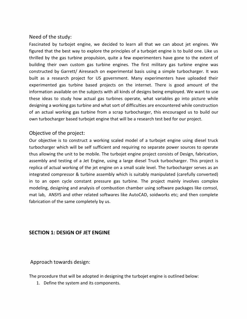
Need of the study:
Fascinated by turbojet engine, we decided to learn all that we can about jet engines. We
figured that the best way to explore the principles of a turbojet engine is to build one. Like us
thrilled by the gas turbine propulsion, quite a few experimenters have gone to the extent of
building their own custom gas turbine engines. The first military gas turbine engine was
constructed by Garrett/ Aireseach on experimental basis using a simple turbocharger. It was
built as a research project for US government. Many experimenters have uploaded their
experimented gas turbine based projects on the internet. There is good amount of the
information available on the subjects with all kinds of designs being employed. We want to use
these ideas to study how actual gas turbines operate, what variables go into picture while
designing a working gas turbine and what sort of difficulties are encountered while construction
of an actual working gas turbine from a scrap turbocharger, this encouraged us to build our
own turbocharger based turbojet engine that will be a research test bed for our project.
Objective of the project:
Our objective is to construct a working scaled model of a turbojet engine using diesel truck
turbocharger which will be self sufficient and requiring no separate power sources to operate
thus allowing the unit to be mobile. The turbojet engine project consists of Design, fabrication,
assembly and testing of a Jet Engine, using a large diesel Truck turbocharger. This project is
replica of actual working of the jet engine on a small scale level. The turbocharger serves as an
integrated compressor & turbine assembly which is suitably manipulated (carefully converted)
in to an open cycle constant pressure gas turbine. The project mainly involves complex
modeling, designing and analysis of combustion chamber using software packages like comsol,
mat lab, ANSYS and other related softwares like AutoCAD, soidworks etc; and then complete
fabrication of the same completely by us.
SECTION 1: DESIGN OF JET ENGINE
Approach towards design:
The procedure that will be adopted in designing the turbojet engine is outlined below:
1. Define the system and its components.

2. Build up the physical/Block model describing all the components.
3. Obtain the equivalent diagrammatic representation of the block model.
4. Formulate the mathematical model and describe the assumptions made.
5. Write down the equations describing the model.
6. Solve the equations for desired output variables.
7. Examine the solution and variables.
8. Apply the necessary corrections to subvert the idealized corrections made in both the
physical and the mathematical model.
9. Reanalyze and Redesign till the solutions obtained are compatible with the results
expected of the actual system.
10. Detailed Design and selection of the various components based on the results obtained
in the analyses of the mathematical model.
Definition of the system:
A Turbojet engine is an engine that accelerates a fluid into its surrounding environment to form
a fast-moving jet. The reaction felt by the engine to this expulsion is the thrust force, which acts
in the opposite direction to the jet. A Turbojet engine is an assemblage of five important
components viz a Compressor coupled to a Turbine , Combustion chamber, Diffuser, Nozzle and
Hydrostatic bearing. All the components when assembled together form what is called as a
Turbojet engine.
Block Diagram of Turbojet Engine

Description of the block diagram:
The entire block circuit of the engine has been divided into three major units for the sake of the
simplicity of understanding. The three major sub units are listed below
1. The Turbocharger unit
2. The Hydrostatic lubrication unit and
3. The Combustion system
Each of these three units is further sub divided into sub units, brief description of which is given
below:

The Turbocharger Unit:
Fig: The Turbocharger unit
This unit is an assembly of an inlet diffuser, a huge diesel truck turbocharger and an exhaust
nozzle.
Turbocharger
A turbocharger is a centrifugal compressor powered by a turbine that is driven by an engine's
exhaust gases. A turbocharger's purpose is to compress the oxygen entering a car's engine,
increasing the amount of oxygen that enters and thereby increasing the power output. The
turbocharger is powered by the car's own exhaust gases. In other words, a turbocharger takes a
by-product of the engine that would otherwise be useless, and uses it to increase the car's
horsepower.
Turbocharger compressor: Turbocharger compressors are generally centrifugal compressors
consisting of three essential components: compressor wheel, diffuser, and housing. With the
rotational speed of the wheel, air is drawn in axially, accelerated to high velocity and then
expelled in a radial direction.
Turbocharger turbine: The turbocharger turbine, which consists of a turbine wheel and turbine
housing, converts the engine exhaust gas into mechanical energy to drive the compressor. The
gas, which is restricted by the turbine's flow cross-sectional area, results in a pressure and
temperature drop between the inlet and outlet. This pressure drop is converted by the turbine
into kinetic energy to drive the turbine wheel.
Propelling Nozzle
The propelling nozzle is the key component of all jet engines as it creates the exhaust jet.
Propelling nozzles turn pressurized, slow moving, hot gas, into lower pressure, fast moving
colder gas by adiabatic expansion. Propelling nozzles can be subsonic, sonic, or supersonic, but
in normal operation nozzles are usually sonic or supersonic. Nozzles operate to constrict the
flow, and hence help raise the pressure in the engine, and physically the nozzles are very
typically convergent, or convergent-divergent. Convergent-divergent nozzles can give
supersonic jet velocity within the divergent section, whereas in a convergent nozzle the exhaust
fluid cannot exceed the speed of sound of the gas within the nozzle. The nozzle shown in the
figure is a convergent type nozzle.
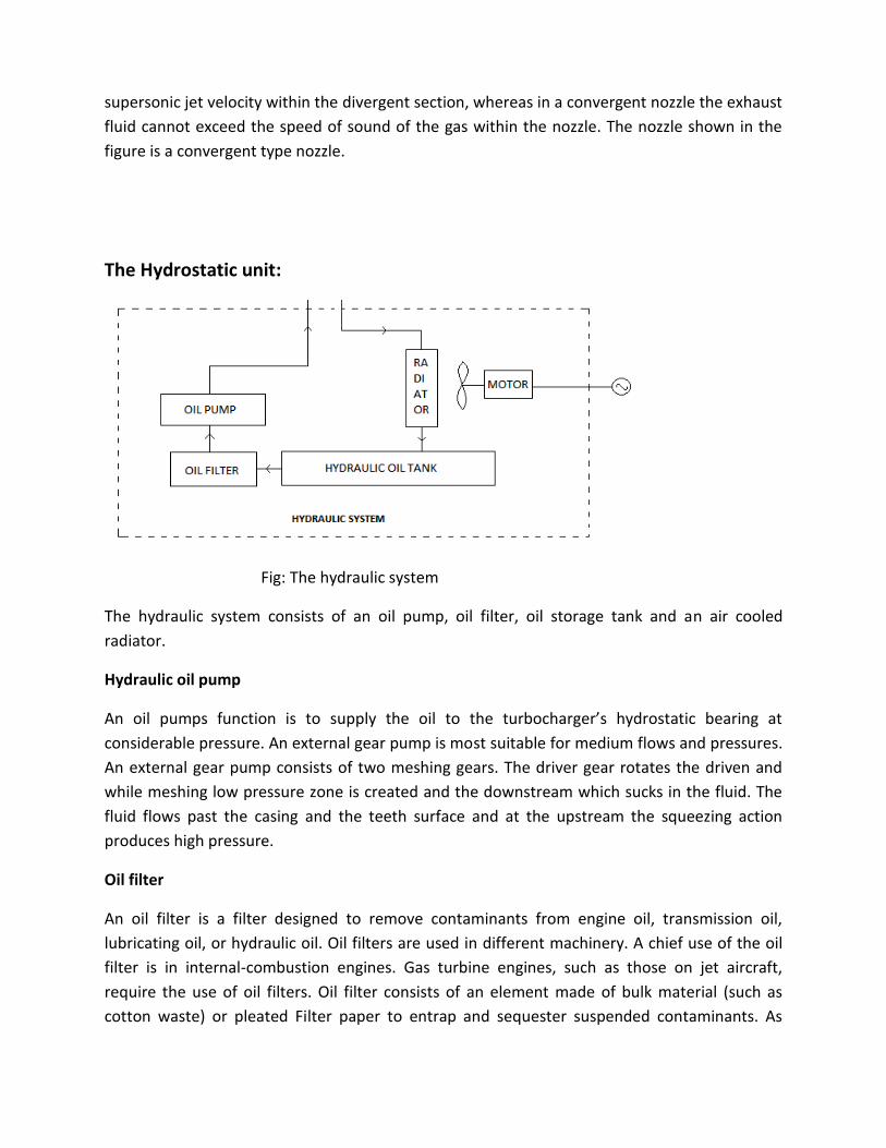
The Hydrostatic unit:
Fig: The hydraulic system
The hydraulic system consists of an oil pump, oil filter, oil storage tank and an air cooled
radiator.
Hydraulic oil pump
An oil pumps function is to supply the oil to the turbocharger’s hydrostatic bearing at
considerable pressure. An external gear pump is most suitable for medium flows and pressures.
An external gear pump consists of two meshing gears. The driver gear rotates the driven and
while meshing low pressure zone is created and the downstream which sucks in the fluid. The
fluid flows past the casing and the teeth surface and at the upstream the squeezing action
produces high pressure.
Oil filter
An oil filter is a filter designed to remove contaminants from engine oil, transmission oil,
lubricating oil, or hydraulic oil. Oil filters are used in different machinery. A chief use of the oil
filter is in internal-combustion engines. Gas turbine engines, such as those on jet aircraft,
require the use of oil filters. Oil filter consists of an element made of bulk material (such as
cotton waste) or pleated Filter paper to entrap and sequester suspended contaminants. As

material builds up on (or in) the filtration medium, oil flow is progressively restricted. This
requires periodic replacement of the filter element
Oil storage tank
Gas turbines will have integral lubricating systems to prevent damage caused by excessive
friction. Often a portion of the lubricating oil is used in the hydraulic oil systems for hydraulic
control devices. Lubricating oil is typically stored in integral stainless steel and carbon steel
tanks that are monitored for level
Radiator
Radiators are heat exchangers used to transfer the thermal energy from one medium to
another for the purpose of cooling and heating. To cool down the engine, coolant heated from
flowing through the engine is fed into the header of the radiator via the inlet and then cools
down as it circulates through the tubes to the opposite header and cold coolant exits back into
the engine via the outlet, and the cycle is repeated. As it circulates through the tubes, the
coolant transfers its heat to the tubes which, in turn, transfer the heat to the fins that are
lodged between each row of tubes. The fins then radiate the heat transferred by the tubes to
the surrounding air, hence the term radiator
The combustion system:
Fig: The combustion system
The combustion system consists of the combustion chamber, the ignition system, and the fuel
pumping system which consists of fuel pump, fuel filter and fuel tank.
A gas turbine combustion chamber can be defined as a chamber which provides a space for
formation of air fuel mixture, its combustion and thus formation of high temperature gases at
highest combustion efficiency with minimum loss of chamber pressure.

The fig above is the cross-sectional view of the combustion chamber. It consists of the outer
cylinder called casing and the inner cylinder called flame tube. The casing and the flame tube
are both made up of the sheet metal. The flame tube is supported in the outer casing. The
flame tube consists of the holes which are symmetrically drilled on the surface of the flame
tube. The fuel nozzle situated at the center of the snout sprays the pressurized fuel into fine
droplets. The flame tube is divided into three zones on the basis of the functionality of each
zone. The three zones are primary, secondary and tertiary zones. These zones contain primary,
secondary and tertiary holes respectively.
The combustor is a critical component since it has to operate at reliably high temperatures and
provide suitable temperature distribution of hot gases at the entry to the turbine and create a
minimum amount of pollutants over a long operating life. The operational requirement of a gas
turbine combustion chamber is that even if the atmospheric conditions change, the combustor
must deal with continuously varying fuel flow without allowing the engine to flame out or
exceed temperature limits. The size and the design of the gas turbine combustion chamber are
very critical for the efficient operation of the combustion chamber and it varies with the
requirements.
Ignition system
The ignition system consists of 230V AC supply, an ignition coil, ignition coil driver circuit and a
spark plug. The function of an ignition system is to produce high intensity spark at equal
intervals of time. The 230V AC acts as a power source. 230V AC voltage is applied to the ignition
coil which is transformer. The ignition coil transforms the 230V AC into 15,000V AC. This
temporary surge of high voltage is enough to produce high intensity spark. The ignition coil
driver circuit serves to break and make the circuit to obtain spark at equal intervals of time
Fuel pumping system
Fuel tank
A fuel tank is safe container for flammable fluids. Though any storage tank for fuel may be so
called, the term is typically applied to part of an engine system in which the fuel is stored and
propelled into an engine
Fuel filter
A fuel filter screens out dirt and rust particles from the fuel, normally made into cartridges
containing a filter paper. They are found in most internal combustion engines. Unfiltered fuel
may contain several kinds of contamination, for example paint chips and dirt that has been

knocked into the tank while filling, or rust caused by moisture in a steel tank. If these
substances are not removed before the fuel enters the system, they will cause rapid wear and
failure of the fuel pump and injectors, due to the abrasive action of the particles on the high-
precision components used in modern injection systems. Fuel filters also improve performance,
as the fewer contaminants present in the fuel, the more efficiently it can be burnt.
Fuel pump
A fuel pump for jet engine is required to deliver fuel in small quantities at extremely high
pressures to achieve the required atomization. An internal gear pump is most suitable for such
application. An internal gear pump functions in the similar way as that of external gear pump
except that the meshing gears are internal rather than external.
Equivalent Diagrammatic Representation of the physical model:
The equivalent diagrammatic representation of the physical model is nothing but
representation with the blocks replaced by the equivalent symbols for each component. It helps
in easy understanding of the circuit diagram. The main feature of the diagrammatic
representation is the elimination of the need to label the components, once the symbols for
each component is known no further aid is required for understanding the circuit diagram. The
diagrammatic model for the above block model is constructed below.

Theoretical working of the model:
In order to understand the working of the jet engine model one has to know the principle of
working of the gas turbine. A gas turbine consists of three basic units’ viz. a compressor
(radial/axial), a turbine (impulse/reaction) and a combustion chamber.
In order to produce an expansion through a turbine a pressure ratio must be provided and the
first necessary step in the cycle of the gas turbine plant must therefore be compression of the
working fluid. If after compression, the working fluid was to be expanded directly in the turbine
and there were no losses in either of the component, the power developed by the turbine
would just equal that absorbed by the compressor. Thus if the two were coupled together the
combination would do no more than turn itself round. But the power developed by the turbine
can be increased by addition of the energy to raise the temperature of the working fluid prior

to expansion. Since the working fluid is air a very suitable means of doing this is by the
combustion of the fuel in the air which has been compressed. Expansion of the hot working
fluid then produces greater power output from the turbine, so that it is able to provide a useful
output in addition to driving compressor. This represents the gas turbine or internal
combustion turbine in its simplest form. The three components viz. compressor, turbine and
the combustion chamber connected together are shown diagrammatically in fig below.
Fig: Simple gas turbine system
Having understood the working of a simple gas turbine, understanding the working of the jet
engine project shouldn’t be difficult because the working cycle of the model is same as that of
simple gas turbine. For the sake of simplicity the working of the model is explained in three
stages again on the basis of the functionality.
The Turbocharger unit:
Fig: Working of Turbocharger

The turbojet engine project makes use of a large diesel truck turbocharger; this is simply
because the turbocharger serves as an integrated compressor and turbine assembly. Thus
eliminating to construct or separately search for the individual compressor and turbine units.
This reduces a great deal of task as far as making of the project is concerned. The construction
of the turbocharger has already been explained in the component description, it resembles very
much like an actual gas turbine with centrifugal compressor coupled to the radial turbine,
supported by a hydrodynamic bearing system. The combustion chamber is not present in
turbocharger. The working cycle of the turbocharger matches with that of the simple gas
turbine. Thus the functional working of the turbocharger atleast for this project is same as that
of the simple gas turbine. The working of the turbocharger is explained below.
Working of turbocharger:
1. Through the air inlet the ambient air enters the compressor of the turbo.
2. The air is then compressed to increased density (mass/unit volume flow). Air enters the
compressor at a temperature equivalent to atmosphere, but as compression causes the
temperature to rise, it leaves the compressor at temperatures of 200 degrees C and
more at high boost applications.
3. Sometimes a charge air cooler (intercooler) is employed after compressor unit that cools
the compressed air to further increase its density and thus the amount of oxygen in
same volume of air charge.
4. After passing through the outlet of the compressor, the air enters the combustion
chamber where the air is mixed with the fuel to form a combustible air fuel mixture
which is then burned.
5. After the air fuel mixture is burned in the combustion chamber it then flows into the
turbine housing.
6. The high temperature gases then continue on to the radial turbine blades. The turbine
rotates due to the impulse action of the high temperature high pressure gases.
7. A pressure and temperature drop occurs (heat expansion) across the turbine, which
harnesses the exhaust gas energy to provide the power necessary to drive the
compressor.
8. Not all the power produced by the turbocharger turbine is used to drive the
compressor, part of the energy of the hot gases is used to drive the compressor and part
is exhausted to the atmosphere.
9. In order to make some use of these exhausting hot gases which is otherwise wasted, we
make use of an exhaust nozzle. The exhaust nozzle is a convergent nozzle which
adiabatically converts the pressure energy of the exhaust gases in to kinetic energy. This
kinetic energy is used to get the useful thrust which can be suitably used for propulsive
application.
The combustion system:
The working of the turbojet engine using a turbocharger is simply not possible without a
combustion system. This makes combustion system extremely crucial in the overall functioning
of the engine. The combustion system forms the heart of the engine; when this heart stops
functioning, the functioning of all other related component ceases. The combustion system as
said earlier consists of a combustion chamber, an ignition system and a fuel pumping system.
The combustion chamber forms the main mixing zone to achieve the stoichiometric air fuel
ratio. In order to produce good stoichiometric air fuel mixture, right quantities of the fuel has to
be mixed with the air continuously. Thus a fuel pumping system is the used here. The fuel pump
produces sufficiently pressurized fuel which is then injected in to the combustion chamber by
means of a spray nozzle. In order to produce good air fuel mixture the spray characteristics of
the spray nozzle is to be given important consideration.
This stoichiometric mixture is then ignited by means of an ignition system. The ignition system
consists of a high intensity spark plug producing a spark of high intensity. The energy for the
spark is obtained from a 12V DC battery. The 12V DC is transformed into 10,000V AC by means
of a transformer. Once the mixture is ignited and the turbine has reached the sufficient speed
the ignition system is switched off.
Inside the combustion chamber the entire volume is divided in to three zones on basis of their
functioning viz. the primary, secondary and the tertiary zone. The ignited mixture in the primary
zone consists of partially burnt hydrocarbons/ fuel. In secondary zone these partially burnt HC’s
are converted into CO2 and H2O thus further releasing energy. The temperatures reached in
the secondary zone can cross 1000 degrees Fahrenheit. Such high temperatures can cause hot
streaks to appear on the turbine blades. In extreme cases the thermal stresses can even cause
buckling of the blades, so to limit the temperature of the hot gases tertiary zone comes to the
rescue. Inside the tertiary zone the high temperature hot gases are mixed with the cold air. The
tertiary chamber functions in two ways viz. by bringing the temperature of the hot gases to the
permissible limits and evenly distributing the heat flux throughout the chamber area. The even
heat distribution helps in minimizing uneven thermal stresses on the turbine blades thus
prolonging life of turbine blades.

The figure below shows the three zones of the combustion chamber with their functioning
diagrammatically.
The hydrodynamic lubrication unit:
The hydrostatic lubrication system consists of an oil pump, oil filter, oil storage tank and an air
cooled radiator. The hydrostatic lubrication unit is meant for the functioning of the
turbocharger bearing. The turbocharger bearing requires continuous pumping of the clean
lubricating oil for its operation. The lubrication oil from the oil pump is fed under pressure into
the bearing housing, towards the journal bearings and the thrust bearing system. After passing
through the bearing system oil flows out to the pan under gravity. The bearing system and the
lubrication mechanism of the turbocharger have been briefly explained below.
The bearing system and lubrication mechanism:

Fig: Lubrication mechanism Fig: Turbo bearing system
The bearing system used is called a hydro-dynamic bearing system. 2 rotating journal bearings
rotate on the shaft and inside the bores in the bearing housing, to control the radial shaft
movements and vibrations.
To control the axial rotor movements, a tapered land type thrust bearing has been positioned
at the compressor end of the bearing housing. The thrust bearing is fixed and does not rotate.
The lubrication system of the thrust bearing has been arranged with a steel thrust collar
supporting the thrust bearing at the bottom side
The entire lubrication system works with a very thin film of oil. The result is, that the complete
rotor is ‘free floating’ on a thin film of oil, both axial and radial
The oil flowing out of the bearing system of the turbocharger can be extremely hot. Most of the
oils cannot withstand temperatures exceeding 150 degree Celsius hence to bring down the
temperature the lubricating oil is allowed to pass through the air cooled radiator. The order in
which the oil flows is from oil tank to oil filter to radiator to oil pump and from oil pump to the
bearing system and finally from hydrodynamic bearing back to the oil tank.
Mathematical model of Turbojet engine:
The mathematical model of turbojet engine is nothing but its thermodynamic model (cycle) and
its complete analysis with all assumptions clearly stated.
The basic thermodynamic cycle of a turbojet engine of p-v and T-s diagrams is given in the
figure below. This is Joule or Brayton cycle. In the analysis of turbojet cycles following
assumptions are made.
1. As the fluid velocities are high in turbojet engine, the change in the kinetic energy
between the inlet and the outlet of each component will be taken into account.
2. The compression and expansion processes are irreversible adiabatic involving increase
in entropy.
3. Fluid friction results in pressure loss in combustion chamber.
4. The mass flow is assumed to be same in spite of addition of fuel.
5. The values of the Cp and of the working fluid vary throughout the cycle due to change
of temperature and due to changes in the chemical composition of the working
medium.

6. Slightly more work than that required for the compression process will be necessary to
overcome bearing and windage friction in the transmission and to drive ancillary
components.
Various processes occurring in the turbojet engine are depicted in the figure above. The
energy equations for these processes are written below.
Inlet diffuser
Ambient air enters the diffuser at the pressure Po, temperature To and velocity Ci. The
pressure rises to P1 at the diffuser exit where the velocity is reduced to Cj. There is no
energy transfer; only energy transformation takes place here.
0 01h h
1
01' 01'
0 0
T P
T P
Therefore pressure ratio,
101' 01'
0 0
P T
P T
Diffuser efficiency is given by;

01 0
01' 0
d
P P
P P
Therefore the static pressure rise in the diffuser is given by;
2 101
0
1(1 )
2d
pM
p
Compressor
Air enters the compressor at reduced velocity and Mach number. Its pressure and enthalpy is
raised to P2 and h2 in the actual process (01-02). Both energy transformation and transfer
occur in this process.
The actual work done by the compressor on the air is given by;
02 01 02 01c pW h h C T T
Compressor pressure rise is given by;
102' 02 '
01 01
P T
P T
Now, the process of compression is not an ideal process so the performance of the compressor
is given by compressor efficiency;
02 ' 01
02 01
c
h h
h h
Thus,
02 01 02' 01 02' 01
1( ) ( )
p
c c
Ch h h h T T
02 01 02 01c pW h h C T T
1
01 0102' 02
01 01
( 1) 1p p
c c
C T C TT P
T P
Combustion Chamber

Air enters the combustion chamber from the compressor at pressure P2, temperature T2. The
combustion of the fuel increases the enthalpy of the air-fuel mixture. The mass of high
temperature gases flowing from the combustion chamber to the turbine and the propelling
nozzle is given by:
. . .
j i fm m m
. .
(1 )j im m f
.
._
f
i
mf fuel ratio
m
Heat supplied in the combustion process is given by;
03 02q h h
= 03 02pC T T
Again due to incomplete combustion the combustion process is inefficient the performance of
the combustion chamber is given by;
03 02
.comb
f
h h
f Q
Where Qf is the specific heat of the fuel.
Turbine
The products of the combustion from the combustion chamber enter the turbine at the
pressure P3, temperature T3. Properties of these gases are different from those of the air
flowing through the inlet diffuser and compressor. Expansion of the gases through the turbine
and the nozzle is shown in the cycle. Both the energy transformation and transfer occur in this
process.
Work done by turbine is given by,

03 04 03 04T pW h h C T T
Pressure ratio of the turbine is given by;
103 03
04' 04 '
P T
P T
Turbine efficiency is given by;
03 04
03 04 '
T
T T
T T
Therefore;
TurbineWork 1
0403 04 03
03
1T p
Ph h C T
P
Also work done by the turbine is used to drive the compressor therefore;
02 01 03 04h h h h
. .i e
1
101 02 04
03
01 03
1 1p
T p
c
C T P PC T
P P
Nozzle
Exhaust gases from the turbine enter the propelling nozzle at pressure P4, temperature T4. The
gases expand adiabatically to the exit pressure P5. There is no energy transfer; only energy
transformation occurs here.
04 05'h h
Nozzle pressure ratio is given by;
104 04
05' 05'
P T
P T
Nozzle efficiency is defined as the ratio of the actual and isentropic values of the enthalpy drop.
04 5
04 5'
noz
h h
h h
Now change in enthalpy in nozzle is given by;
1
504 5 04
04
1noz p
Ph h C T
P
Also;
2
04 52
jCh h
12
504
04
12
j
noz p
c PC T
P
or
1
504
04
2 1j noz p
Pc C T
P
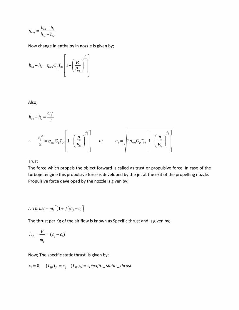
Trust
The force which propels the object forward is called as trust or propulsive force. In case of the
turbojet engine this propulsive force is developed by the jet at the exit of the propelling nozzle.
Propulsive force developed by the nozzle is given by;
..
1i j iThrust m f c c
The thrust per Kg of the air flow is known as Specific thrust and is given by;
.( )SP j i
a
FI c c
m
Now; The specific static thrust is given by;
0ic ( )SP St jI c ( ) _ _SP StI specific static thrust

Hence to develop a large specific thrust jet speed should be as large as possible.
Let maxh be the enthalpy drop in the nozzle corresponding to the velocity jC, then jet speed is
given by;
2
max2
jch
2j pc C T
Data Assumptions:
78%T
85%noz
92%Tran
85%comb
1.4a
1.33g
1.005_ / /paC KJ Kg K
1.147_ / /pgC KJ Kg K
0 293ambT T K
0 0.98ambP P bar
Compressor inlet temperature 01 300T K
Turbine outlet temperature 04 920T K
0.2combP bar
77%c

43_fQ MJ
02
01
_ 2.5P
Pressure RatioP
Output Variables Required:
1. Compressor outlet temperature 02 ?T
2. Turbine inlet temperature 03 ?T
3. Turbine pressure ratio 03
04
?P
P
4. Nozzle outlet temperature 05 ?T
5. Jet speed 5 ?C
6. Intake air mass flow rate .
?am
7. Air-fuel ratio
.
.?a
f
m
m
8. Fuel flow rate .
?fm
9. Exhaust gases mass flow rate .
?gm
Solution:
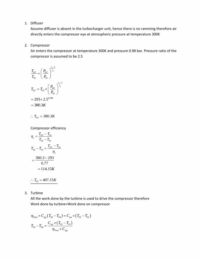
1. Diffuser
Assume diffuser is absent in the turbocharger unit, hence there is no ramming therefore air
directly enters the compressor eye at atmospheric pressure at temperature 300K
2. Compressor
Air enters the compressor at temperature 300K and pressure 0.98 bar. Pressure ratio of the
compressor is assumed to be 2.5
1
02' 02'
01 01
a
aT P
T P
1
02'02' 01
01
a
aPT T
P
0.286293 2.5
380.3K
02' 380.3T K
Compressor efficiency
02 ' 01
02 01
c
T T
T T
02 ' 0102 01
c
T TT T
380.3 293
0.77
114.15K
02 407.15T K
3. Turbine
All the work done by the turbine is used to drive the compressor therefore
Work done by turbine=Work done on compressor
03 04 02 01Tran pg paC T T C T T
02 01
03 04
pa
Tran pg
C T TT T
C

1.005 114.15
0.92 1.147
108.7K
03 04 108.7T T K
Now 04 920T K
03 1028.7T K
Turbine efficiency
03 04 03 1
11
g
g
T
t
T T T
r
1.33 1
1.33
1108.7 0.78 1028.7 1
tr
1.8tr
03 02
04 04
combt
P P Pr
P P
0204
comb
t
P PP
r
2.5 0.2
1.8
1.278
04 1.278P
4. Nozzle
Exhaust gases from turbine outlet enters the propelling nozzle at pressure 04P and
temperature 04T .

1
04 04
5' 5
g
g
T P
T P
1.33 1
1.331.278
1
1.0628
045'
920865.57
1.0628 1.0628
TT K
Nozzle efficiency
04 5'
04 5
noz
T T
T T
04 5'04 5
noz
T TT T
920 865.57
0.85
64.035
5 855.96T K
Jet speed
2
504 5 64.035
2 pg
CT T
C
5 2 pgC C T
2 1147 64.035
383.27 /m s
5 383.27 /C m s
Thrust
.
a j iF m C C

0iC
.
a jF m C
. 1500.39
383.27a
j
Fm
C
.
0.39 /am kg s
Air-Fuel ratio
.
03 02 .fcombh h m C V
. .
03 02 .a fpa combm C T T m C V
.
03 02
..
f pa
comba
C T Tmf
C Vm
= Fuel: Air ratio
1.005 (1028.7 407.15)
0.85 43000
0.017
Therefore Air-Fuel ratio is given by 58.5:1
Fuel flow rate
. .
f am m f
0.39 0.017
36.63 10
0.4 / minkg
.
0.4 / minfm kg
Exhaust gases mass flow rate
. . .
g f am m m
0.39 0.00663

0.4 /kg s
.
0.4 /m kg s
Tabulated Results & its examination:
Sr.
No.
Output Variable Calculated
Values
Expected
Values
Comment on
calculated Values
Status of
acceptance
1 Compressor outlet
temperature 02T
407.15K 425K OK Acceptable
2 Turbine inlet
temperature 03T
1028.7K 1060K OK Acceptable
3 Turbine pressure ratio
03
04
P
P
1.8 2 OK Acceptable
4 Nozzle outlet
temperature 05T
855.96K 850K OK Acceptable
5 Jet speed 5C 383.27m/s 416m/s LESS Acceptable
6 Intake air mass flow rate .
am
0.39kg/s 0.85kg/s LESS Acceptable
7 Air-fuel ratio
.
.
a
f
m
m
58.5:1 90:1 LESS Acceptable
8 Fuel flow rate
.
fm 0.4kg/min 0.56kg/m
in
OK Acceptable
9 Exhaust gases mass flow
rate .
gm
0.4kg/s 1.41kg/s LESS Acceptable
Inferences:
Based on the tabulated results of the above analysis following inferences can be deduced:
1. Due to personal error the results are deviated a little.

2. The assumptions are made merely on the basis of personal judgments and cannot be
justified as such.
3. The assumptions can go wrong in certain cases.
4. The results obtained are within the permissible limits to be accepted
5. There is no further need to apply corrections and reanalyze the calculation at this stage.
Conclusion:
Thus on basis of the inferences made in the above section we have come to the conclusion that
no correction is to be applied for the above calculation; the reanalysis of the design procedure
is thus not required. It can be suitably stated that the design analysis carried out on the basis of
the assumptions made is feasible and the results are within the range of acceptance.

Detailed Design and selection of components
The design and the selection of various components will be completely based on the results
obtained in the analysis of the mathematical model of turbojet engine.
1. Turbocharger
There are a number of factors, such as turbo lag, boost threshold, heat, back-pressure, low-end
torque, and top-end power, that must be taken into account when selecting a turbo. A large
turbo will suffer from turbo lag and won't produce much low-end torque but it also won't put
too much heat to the intake charge, won't have much back-pressure, and will produce loads of
top-end power. A small turbo, on the other hand, won't have much turbo lag and will produce
loads of low-end torque but will also have lots of back-pressure and will add lots of heat to the
intake charge. The turbocharger selection based on the operating characteristics of the
compressor and turbine is widely used for the selection of turbocharger for passenger cars. For
the turbojet engine application the turbocharger is selected on the basis of the compressor and
turbine maps which are explained in the section below.
Operating characteristics of Compressor:
The compressor operating behavior is generally defined by maps showing the relationship
between pressure ratio and volume or mass flow rate. The useable section of the map relating
to centrifugal compressor is limited by the surge and choke lines and the maximum permissible
compressor speed.
Surge line

Fig: Compressor map of a turbocharger for passenger car applications
The map width is limited on the left by the surge line. This is basically "stalling" of the air flow at
the compressor inlet. With too small a volume flow and too high a pressure ratio, the flow can
no longer adhere to the suction side of the blades, with the result that the discharge process is
interrupted. The air flow through the compressor is reversed until a stable pressure ratio with
positive volume flow rate is reached, the pressure builds up again and the cycle repeats. This
flow instability continues at a fixed frequency and the resultant noise is known as "surging".
Choke line
The maximum centrifugal compressor volume flow rate is normally limited by the cross-section
at the compressor inlet. When the flow at the wheel inlet reaches sonic velocity, no further
flow rate increase is possible. The choke line can be recognized by the steeply descending
speed lines at the right on the compressor map.
Operating characteristics Turbine
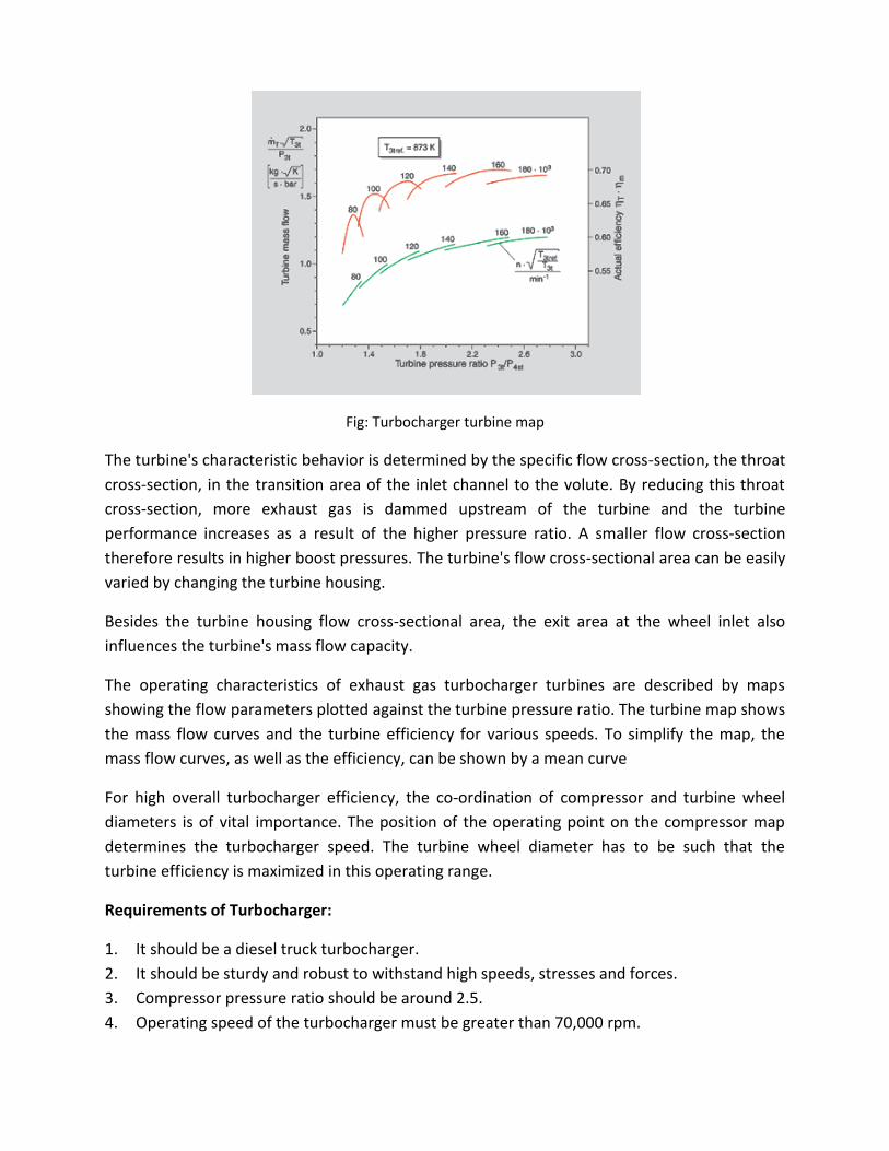
Fig: Turbocharger turbine map
The turbine's characteristic behavior is determined by the specific flow cross-section, the throat
cross-section, in the transition area of the inlet channel to the volute. By reducing this throat
cross-section, more exhaust gas is dammed upstream of the turbine and the turbine
performance increases as a result of the higher pressure ratio. A smaller flow cross-section
therefore results in higher boost pressures. The turbine's flow cross-sectional area can be easily
varied by changing the turbine housing.
Besides the turbine housing flow cross-sectional area, the exit area at the wheel inlet also
influences the turbine's mass flow capacity.
The operating characteristics of exhaust gas turbocharger turbines are described by maps
showing the flow parameters plotted against the turbine pressure ratio. The turbine map shows
the mass flow curves and the turbine efficiency for various speeds. To simplify the map, the
mass flow curves, as well as the efficiency, can be shown by a mean curve
For high overall turbocharger efficiency, the co-ordination of compressor and turbine wheel
diameters is of vital importance. The position of the operating point on the compressor map
determines the turbocharger speed. The turbine wheel diameter has to be such that the
turbine efficiency is maximized in this operating range.
Requirements of Turbocharger:
1. It should be a diesel truck turbocharger.
2. It should be sturdy and robust to withstand high speeds, stresses and forces.
3. Compressor pressure ratio should be around 2.5.
4. Operating speed of the turbocharger must be greater than 70,000 rpm.

5. Turbine pressure ratio/Boost pressure should be high around 2.
6. Individual efficiencies of the compressor and turbine should be high.
7. Turbocharger should be able to withstand high dynamic vibrations.
8. Turbo lag should be minimum
9. Back pressure should be minimum
10. Turbo bearing must be hydrodynamic bearing with forced lubrication mechanism.
11. The lubrication system should be simple and easy to maintain.
12. The turbo lubricant should be easily available and cheap.
13. Operating temperatures of turbine should be high around 1000 degree Celsius.
14. High reliability at top speeds.
15. Overall maintenance of the turbocharger should be easy; turbocharger parts should be
easily available.
Selection of Turbocharger
There are many diesel truck turbochargers manufacturing industries in the world but based on
our requirements of the turbocharger we select CZ STACONICE turbocharger, the details of the
turbocharger is listed below.
MANUFACTURER : CZ STRACONICE
COUNTRY : CZECH REPUBLIC
TYPE : K36 3566 2521
ASSY : K36 79 06
CUSI : TATRA
SERIAL : 247134-97058
APPLICATION : LIAZ,TATRA
MOTOR OUTPUT : 160 - 450 kW
TURBO-CHARGER K36 - 97

Construction drawing:
Graph 1: Compressor map

Graph 2: Turbine map
2. Combustion chamber
This section deals with the detailed design of the combustion chamber of the modeled turbojet
engine. The design includes deciding the dimension of the combustion chamber, their particular
shape, size, and areas of primary, secondary, tertiary zones, location of igniter, areas of the
primary, secondary, tertiary holes and their respective location to achieve self-stabilizing flame.
In the combustion chamber design, the major goals to be achieved are high combustion
efficiency, reduction of visible smoke, reduction of oxides of nitrogen.
The size and shape of the combustion chamber vary with their requirements. A land-based gas
turbine will have least restrictions as far as weight and size is concerned but aircraft application
based gas turbines (Jet engine) will have more restriction on its size and weight. Since our gas
turbine is meant for producing thrust similar to like jet engines of aircraft but on small scale; we
will focus our attention on the combustion chamber of jet aircraft engine. Though it won’t
matter much even if the design is based on the land-based gas turbines, but they are huge,
complicated and too costly to suit our small scale turbojet engine.
Designing a combustion chamber is a complex process; many factors have to be simultaneously
taken into consideration while designing. The shape and size will definitely affect these factors,
like a too long combustor will involve more pressure loss and if the same combustor is too short
it will lead to incomplete combustion. Even size matters, for a small turbocharger it is worth
less to build a huge combustion chamber. All these precautions have been incorporated in the
design procedure of this combustor.
Approach towards combustor design
1. Study of the existing jet aircraft combustion chamber.
2. Deriving empirical relations based of the study.
3. Manipulation of the empirical relations suited for our application.
4. Calculation of the combustor dimensions and other design details based on manipulated
empirical relations.
5. Initial combustor model based on calculations.
6. Incorporation of necessary changes to the initial design to suit practicality and construction
feasibility of the combustor.
7. Final model of combustor.
Some important factors affecting combustor design.
The main factors influencing the design of the combustion chamber for the gas turbines are.
1. The temperature of the gases after the combustion must be comparatively low to suit the
highly stressed turbine materials.
2. At the end of the combustion chamber the temperature distribution must be of known form
if the turbine blades are not to suffer from local overheating. In practice temperature
increases with the radius from root to tip.
3. Combustion must be maintained in the stream of air moving with high velocity of 30-60 m/s
and stable operation is required over a wide range of air/fuel ratio from full load to idling
conditions. The air fuel ration might vary from about 60:1 to 120:1 for simple cycle gas
turbines and from 100:1 to 200:1 if heat exchange is used. Considering that the
Stoichiometric ratio is approximately 15:1 it is clear that high dilution is required to
maintain the temperature level acceptable for turbine blades.
4. The formation of carbon deposits must be avoided, particularly the hard brittle variety.
Small particles carried into the turbine in the high velocity gas stream can erode the blades
and block cooling air passages; furthermore, aerodynamically excited vibration in the
combustion chamber might cause sizable pieces of the carbon to break free, resulting in
even worse damage to the turbine.
5. Avoidance of the smoke in the exhaust is of the major importance for all types of gas
turbine.

6. Although gas turbine combustion systems operate at extremely high efficiencies, they
produce pollutants such as oxides of nitrogen (NOX), carbon monoxide (CO) and unburned
hydrocarbons (UHC) and these must be controlled at very low levels.
Analytical design of combustion chamber for the turbojet engine project:
Before starting the analytical design of the combustion chamber it is essential to keep in mind
what requirements the combustion chamber needs to fulfill.
Requirements of the combustion chamber:
The main function of the combustion chamber for the turbojet engine project is to provide for
the complete combustion of the fuel and air, the air being supplied by the compressor of the
turbocharger and the products of the combustion being delivered to the turbine wheel of the
turbocharger. In carrying out this function, the combustion chamber must fulfill following
requirements.
1. Complete combustion of the fuel must be achieved.
2. The total pressure loss must be minimum
3. Carbon deposits must not be formed under any expected condition of operation
4. Ignition must be reliable and must be accomplished with ease over wide range of
atmospheric conditions
5. Temperature and velocity distribution at the turbine inlet must be controlled
6. The volume and the weight of the combustor must be kept within the reasonable limits.
7. Reliability and endurance should be ascertained
The complete analytical design of the combustion chamber involves following steps.
1. Deciding size and shape of the entire combustion chamber
2. Division of three zones on the flame tube
3. Flame stabilization technique
4. Location of fuel spray nozzle
5. Calculation of total area of holes
6. Calculation of number of holes in each zone
7. Location of holes in each zone
8. Location of igniter
9. Final assembly of the combustion chamber with all details clearly depicted
1. Size and shape of the combustion chamber
This is extremely vital step in achieving an effectively functioning combustion chamber. The size
& shape will definitely affect other factors like a too long combustion chamber will have a
benefit of having a good mixing length and thus more chances of complete combustion but at
the same time it will involve a more pressure loss and thus loss in efficiency. On the other hand
a too short combustion chamber has an advantage of minimum loss of the pressure but at the
same time it will lead to incomplete combustion thus a tradeoff has to be achieved between
minimum loss of the combustor pressure and high combustion efficiency. Besides the technical
aspect it is also essential to ascertain the feasibility consideration for example it is worthless to
build a huge combustion chamber for a small size turbocharger. All these factors are taken into
consideration in deciding size and shape of the combustion chamber.
Size of the combustion chamber
Deciding size of the combustion chamber involves deciding the length and the diameter of the
flame tube and the outer air casing. The following empirical relation will help in deciding the
above factors.
Empirical Relations:
Overall length of the outer casing = 6 Inducer diameter
Overall diameter of the outer casing = 2 Inducer diameter
Length of the flame tube = 6 Inducer diameter
Diameter of the flame tube = 2 Inducer diameter Air gap between outer casing &flame tube
Optimum air gap between outer casing and flame tube = 0.5 inch
Optimized dimensions of the combustion chamber
The empirical relation gives a basic idea of the size of the combustion chamber for starters. It is
a crude judgmental approach for deciding the dimensions and needs to be optimized suited for
our application. The following refinements have been made based on the feasibility and
economical point of view.
Overall length of the outer casing:
Overall diameter of the outer casing:
Length of the flame tube:
Diameter of the flame tube:
Optimum air gap between outer casing and flame tube
Fig: Initial design depicting the dimensions

Shape of the combustion chamber
The shape of the combustion chamber is figured out based on three factors i.e. the compressor
outlet, the turbine inlet and the arrangement of the combustion chamber on to the
turbocharger.
The combustion chamber is arranged coaxially with the turbine inlet flange, i.e. the exhaust end
or the exhaust flange of the combustion chamber is coaxial with the inlet flange of turbine. To
do so it is essential to match the end dimensions of both the flanges thus the combustion
chamber is provided with a taper at the exhaust end. The combustion chamber will lie vertically
in line with the turbine flange and thus compressor end is connected to the combustion
chamber via ducts with series of bends. Note that the shape of only outer casing has been
refined the flame tube has not been touched. The basic shape is depicted in the fig below.
Fig: Initial design of combustor with taper at exhaust end and ducts at the compressor end.
The next step is mounting the flame tube in the outer casing. There are certain requirements to
be fulfilled in designing the mounting system for the flame tube in the outer casing, the
requirements are listed below.
i. The mounting should be strong enough to hold the flame tube in place.
ii. The mounting system should be capable to withstand high axial forces of combustion.
iii. It should be capable to withstand high temperatures of combustion.
iv. It should be simple in design.
v. It should assists in easy assembling and disassembling of flame tube for maintenance.
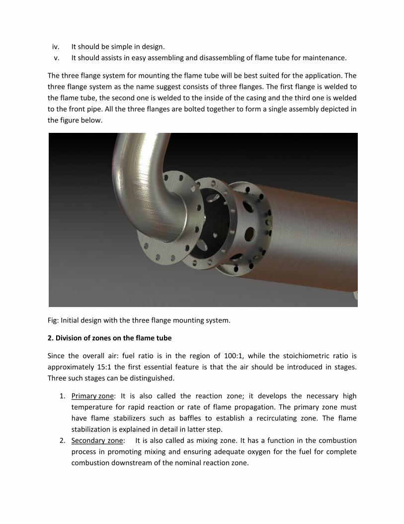
The three flange system for mounting the flame tube will be best suited for the application. The
three flange system as the name suggest consists of three flanges. The first flange is welded to
the flame tube, the second one is welded to the inside of the casing and the third one is welded
to the front pipe. All the three flanges are bolted together to form a single assembly depicted in
the figure below.
Fig: Initial design with the three flange mounting system.
2. Division of zones on the flame tube
Since the overall air: fuel ratio is in the region of 100:1, while the stoichiometric ratio is
approximately 15:1 the first essential feature is that the air should be introduced in stages.
Three such stages can be distinguished.
1. Primary zone: It is also called the reaction zone; it develops the necessary high
temperature for rapid reaction or rate of flame propagation. The primary zone must
have flame stabilizers such as baffles to establish a recirculating zone. The flame
stabilization is explained in detail in latter step.
2. Secondary zone: It is also called as mixing zone. It has a function in the combustion
process in promoting mixing and ensuring adequate oxygen for the fuel for complete
combustion downstream of the nominal reaction zone.

3. Tertiary zone: It is also called as dilution zone. It helps in bringing down the
temperature of the products of combustion to the required level acceptable to the
turbine blades.
Division of flame tube is shown in the figure below:
3. Flame stabilization
The zonal method of introducing the air cannot by itself give a self piloting flame in air stream
which is moving in order of magnitude faster than flame speed in the burning mixture. The
essential requirement is therefore to provide a recirculation zone which directs some of the
burning mixture in the primary zone back into the incoming fuel and air. To achieve this the fuel
is injected in the same direction as the air stream, and the primary air is introduced through the
twisted radial vanes, known as swirl vanes, so that the resulting vortex motion will induce a
region of low pressure along the axis of chamber. This vortex motion is enhanced by secondary
sir through the short tangential chutes in the flame tube. The net result is that burning gases
tend to flow towards the region of low pressure, and some portion of them is swept round
towards the jet of the fuel.
Flame tube
Primary zone Secondary zone Tertiary zone

Fig: Swirl vanes
In order to incorporate the swirl vanes in the flame tube an arrangement has to be made in the
primary zone to mount the swirl vanes and this is achieved by introducing the flare in the flame
tube. The flare performs two functions i.e. it has an arrangements for mounting the swirl vanes
and it also has tangential holes for introducing the short tangential chutes in the flame tube.
Fig: Flare with Swirl vanes
Thus flame tube should accommodate space for the flare other than three zones. The sub-
division of the flame tube is shown in the fig below.
4. Location of fuel spray nozzle
The design of the flame tube demands that the fuel spray nozzle should be capable of spraying
atomized fuel in the direction of the air i.e. along the axis of the flame tube, thus in order to
stick to the design, fuel nozzle is arranged coaxially with the swirl vanes. The swirl vanes have a
central blank hole for mounting the fuel nozzle.
Flame tube
Flare Primary zone Secondary zone Tertiary zone
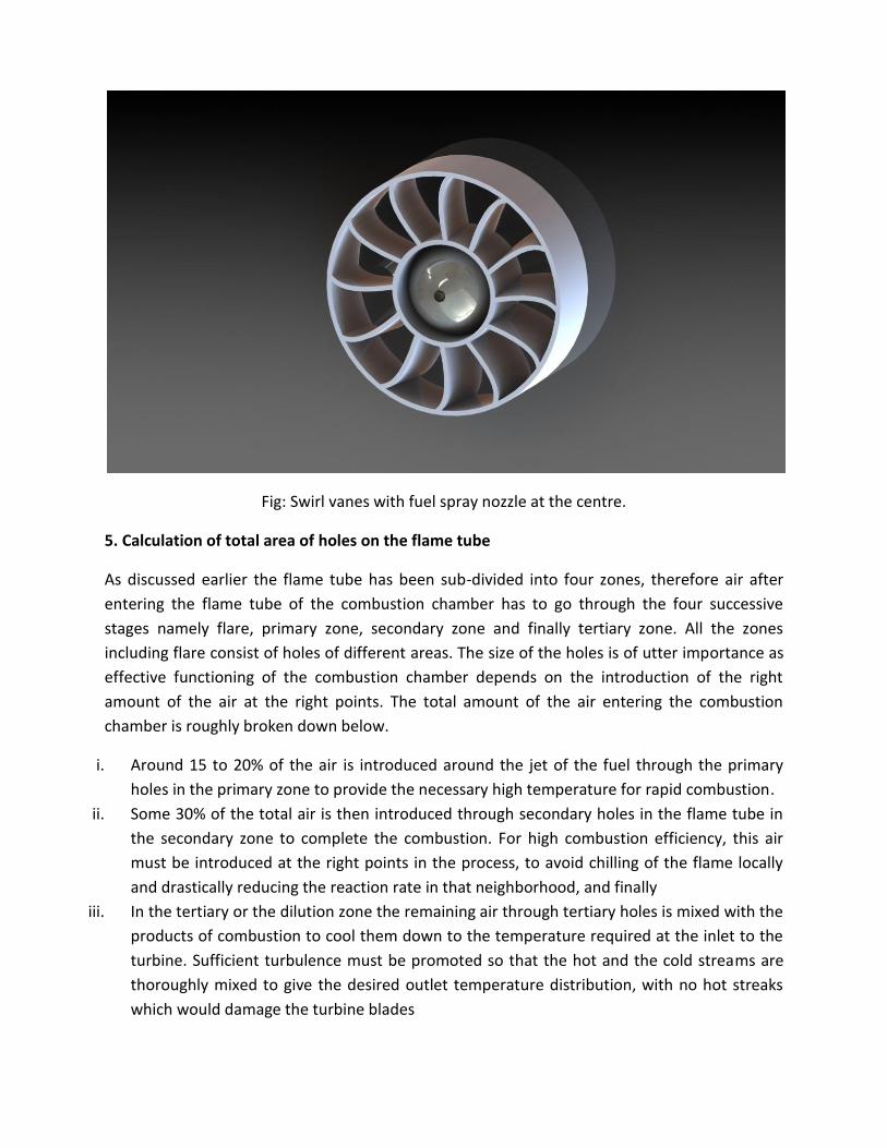
Fig: Swirl vanes with fuel spray nozzle at the centre.
5. Calculation of total area of holes on the flame tube
As discussed earlier the flame tube has been sub-divided into four zones, therefore air after
entering the flame tube of the combustion chamber has to go through the four successive
stages namely flare, primary zone, secondary zone and finally tertiary zone. All the zones
including flare consist of holes of different areas. The size of the holes is of utter importance as
effective functioning of the combustion chamber depends on the introduction of the right
amount of the air at the right points. The total amount of the air entering the combustion
chamber is roughly broken down below.
i. Around 15 to 20% of the air is introduced around the jet of the fuel through the primary
holes in the primary zone to provide the necessary high temperature for rapid combustion.
ii. Some 30% of the total air is then introduced through secondary holes in the flame tube in
the secondary zone to complete the combustion. For high combustion efficiency, this air
must be introduced at the right points in the process, to avoid chilling of the flame locally
and drastically reducing the reaction rate in that neighborhood, and finally
iii. In the tertiary or the dilution zone the remaining air through tertiary holes is mixed with the
products of combustion to cool them down to the temperature required at the inlet to the
turbine. Sufficient turbulence must be promoted so that the hot and the cold streams are
thoroughly mixed to give the desired outlet temperature distribution, with no hot streaks
which would damage the turbine blades

Empirical relations
Total area of the holes = Inducer area of turbocharger =i.e.
Primary holes + Secondary holes + Tertiary holes + Flare holes & Swirl vanes = 6083 mm2 .
Flare holes and Swirl vanes = 10-20% (Total area of holes) =912.3 mm2
Primary hole area = 15-20% (Total area of holes) =1216.42 mm2
Secondary hole area = 30% (Total area of holes) =1824.6 mm2
Tertiary hole area = Remaining % (Total area of holes) =3041.6 mm2
Calculation of the actual values by optimization:
The optimization is based on the vigorous trial and error technique and is finely tuned with the
practicability from the construction and continuous operation point of view. Thus the
optimization has no theoretical base as such; it is merely experimental and judgmental
approach.
Flare holes and Swirl vanes = % (Total area of holes) =1100 mm2
Primary hole area = % (Total area of holes) =1400 mm2
Secondary hole area = % (Total area of holes) =2000 mm2
Tertiary hole area = % (Total area of holes) =3200 mm2
6. Calculation of size and number of holes in each zone:
This section of the design is again based on the experimental data and the judgmental methods
supported by theory. The dimension and the number of holes in each zone are so decided so as
to give maximum benefit from the combustion point of view. The description below will give an
indication of the necessity of the precise size and the number of the holes in each zone.
Flare with Swirl vanes: Flare and Swirl vanes acts as flame stabilizers which help to establish a
recirculation zone for formation of the sustaining flame. But in addition to stabilization vigorous
mixing action must be provided in order to mix air and fuel and then to burn unburnt mixture
with burnt gases. The stability parameter indicates that it is better to provide a small number of
large baffles than a large number of small baffles.
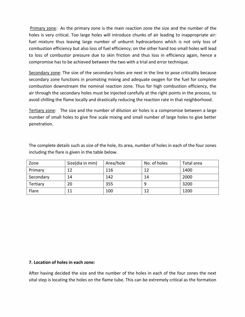
Primary zone: As the primary zone is the main reaction zone the size and the number of the
holes is very critical. Too large holes will introduce chunks of air leading to inappropriate air:
fuel mixture thus leaving large number of unburnt hydrocarbons which is not only loss of
combustion efficiency but also loss of fuel efficiency; on the other hand too small holes will lead
to loss of combustor pressure due to skin friction and thus loss in efficiency again, hence a
compromise has to be achieved between the two with a trial and error technique.
Secondary zone: The size of the secondary holes are next in the line to pose criticality because
secondary zone functions in promoting mixing and adequate oxygen for the fuel for complete
combustion downstream the nominal reaction zone. Thus for high combustion efficiency, the
air through the secondary holes must be injected carefully at the right points in the process, to
avoid chilling the flame locally and drastically reducing the reaction rate in that neighborhood.
Tertiary zone: The size and the number of dilution air holes is a compromise between a large
number of small holes to give fine scale mixing and small number of large holes to give better
penetration.
The complete details such as size of the hole, its area, number of holes in each of the four zones
including the flare is given in the table below.
Zone Size(dia in mm) Area/hole No. of holes Total area
Primary 12 116 12 1400
Secondary 14 142 14 2000
Tertiary 20 355 9 3200
Flare 11 100 12 1200
7. Location of holes in each zone:
After having decided the size and the number of the holes in each of the four zones the next
vital step is locating the holes on the flame tube. This can be extremely critical as the formation
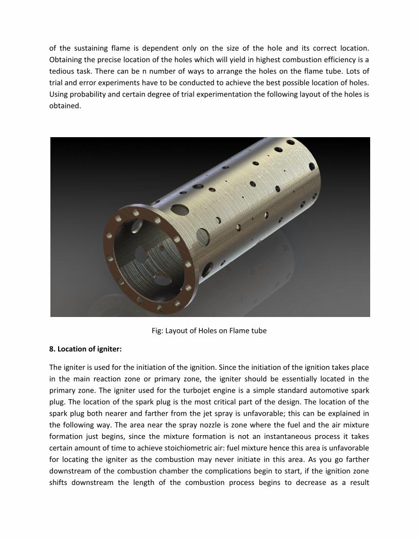
of the sustaining flame is dependent only on the size of the hole and its correct location.
Obtaining the precise location of the holes which will yield in highest combustion efficiency is a
tedious task. There can be n number of ways to arrange the holes on the flame tube. Lots of
trial and error experiments have to be conducted to achieve the best possible location of holes.
Using probability and certain degree of trial experimentation the following layout of the holes is
obtained.
Fig: Layout of Holes on Flame tube
8. Location of igniter:
The igniter is used for the initiation of the ignition. Since the initiation of the ignition takes place
in the main reaction zone or primary zone, the igniter should be essentially located in the
primary zone. The igniter used for the turbojet engine is a simple standard automotive spark
plug. The location of the spark plug is the most critical part of the design. The location of the
spark plug both nearer and farther from the jet spray is unfavorable; this can be explained in
the following way. The area near the spray nozzle is zone where the fuel and the air mixture
formation just begins, since the mixture formation is not an instantaneous process it takes
certain amount of time to achieve stoichiometric air: fuel mixture hence this area is unfavorable
for locating the igniter as the combustion may never initiate in this area. As you go farther
downstream of the combustion chamber the complications begin to start, if the ignition zone
shifts downstream the length of the combustion process begins to decrease as a result

combustion tends to remain incomplete in the combustion chamber. The completion of the
combustion takes place in the turbine zone which increases the chances of turbine meltdown
due to extreme temperatures. Thus again a precise compromise has to be reached here this
time between probability of combustion initiation and possibility of turbine meltdown.
After vigorous trial and error the location of the spark plug is suitably achieved.
9. Final assembly of the combustion chamber
Fig: Final assembly of combustion chamber modeled in solidworks
The complete layout of the combustion chamber is given on the next page.
Nozzle
Analytical design of nozzle
Data:
04
05
05
04
5
.
1.278
1
855.96
920
0.85
383.27 /
1.333
0.39 /
a
nozzle
a
P
P P
T K
T K
C m s
m kg s

Now, we should check to compare the operating pressure ratio, 05
04
P
P, of nozzle with the
corresponding critical pressure ratio, 04
cP
P. If 05
04
P
P> then a simple convergent nozzle is sufficient
to give full expansion of the gases, if it is smaller then a convergent-divergent nozzle would be
necessary.
05
04
10.7824
1.278
P
P
Critical pressure ratio is given by:
1
04
2
1
cP
P
4.03
04
20.5404
1.33 1
cP
P
05
04 04
cP P
P P
Thus it can be seen that complete expansion of the gases is possible in convergent nozzle,
hence no need of convergent-divergent nozzle.
Now,
5 5 5p RT
Specific volume is given by:
55
5
RT
p
Where ( 1) 1147 0.33
284.6 /1.33
pCR J kgK
3
5 5
284.6 855.62.436 /
1 10m kg
Let ‘A’ be the required throat area of the propelling nozzle then,
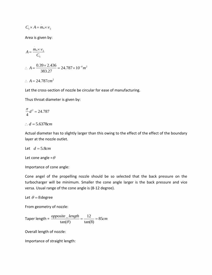
.
5 5aC A m
Area is given by:
.
5
5
amA
C
4 20.39 2.43624.787 10
383.27A m
224.787A cm
Let the cross-section of nozzle be circular for ease of manufacturing.
Thus throat diameter is given by:
2 24.7874
d
5.6378d cm
Actual diameter has to slightly larger than this owing to the effect of the effect of the boundary
layer at the nozzle outlet.
Let 5.8d cm
Let cone angle =
Importance of cone angle:
Cone angel of the propelling nozzle should be so selected that the back pressure on the
turbocharger will be minimum. Smaller the cone angle larger is the back pressure and vice
versa. Usual range of the cone angle is (8-12 degree).
Let 8 degree
From geometry of nozzle:
Taper length = _ 12
85tan( ) tan(8)
opposite lengthcm
Overall length of nozzle:
Importance of straight length:

Back pressure on the turbocharger is partly affected by the straight length of the nozzle.
Smaller the straight length larger is the back pressure and larger the straight length more is the
friction loss, thus a compromise has to be reached between the less back pressure and less
losses.
Let Straight length = 325 mm
Overall length = 410 mm
Propelling Nozzle Dimensions:
Sr No Dimension Parameter Units (mm)
1 Nozzle tube diameter 82
2 Throat diameter 58
3 Cone angle 8 degrees
4 Cone length 85
5 Straight length 325
6 Overall length 410
7 Tube thickness 2
Fig: Nozzle
Gear pump
Selection of gear pump

General requirements of gear pumps for fuel pumping and lubrication:
• Robust and reliable operation
• High and low viscous products
• Smooth flow
• Simple design - only two moving parts
• Easy maintenance
• Reduced down time for service
• Wide range of materials
• High efficiency
• Conforms to API 676
TECHNICAL DATA SHEET (PUMP) EXTERNAL GEAR PUMP FOR LUBRICATION
TYPE : EXTERNAL SPUR GEAR PUMP
DUTY : CONTINUOUS
INSTALLATION (INDOOR/OUTDOOR) : OUTDOOR/INDOOR
LIQUID HANDLED : OIL (SAE 5W/50)
CAPACITY – : 0-900 LPH (10 LPM)
OPERATING PRESSURE : 10 Kg/Cm2
DISCHARGE PRESSURE : 10 Kg/Cm2
HEAD (M) : 0-10 MTR
ACCURACY : +/- 1%
MAXIMUM ALLOWABLE SPEED (SPM) : 200 SPM
TYPE OF CONTROL (MANUAL/AUTOMATIC) : MANUAL
SUCTION PRESSURE : FLOODED
METHOD OF LUBRICATION : SUBMERGED TYPE
LUBRICANT RECOMMENDED
TYPE OF GEAR
PUMP HOUSING
GLAND PACKING
:
:
:
:
ENCLO/SA 460
SPUR GEAR
CASTING
PTFE

Fig: External gear pump
TECHNICAL DATA SHEET (PUMP) INTERNAL GEAR PUMP FOR FUEL PUMPING
TYPE : INTERNAL GEAR PUMP
DUTY : CONTINUOUS
INSTALLATION (INDOOR/OUTDOOR) : OUTDOOR/INDOOR
LIQUID HANDLED : PETROCHEMICAL -KEROSENE
CAPACITY – : 0-900 LPH (5 LPM)
OPERATING PRESSURE : 15 Kg/Cm2
DISCHARGE PRESSURE : 20 Kg/Cm2
ACCURACY : +/- 1%
MAXIMUM ALLOWABLE SPEED (SPM) : 200 SPM
TYPE OF CONTROL (MANUAL/AUTOMATIC) : MANUAL
SUCTION PRESSURE : FLOODED
METHOD OF LUBRICATION : SUBMERGED TYPE
LUBRICANT RECOMMENDED
TYPE OF GEAR
PUMP HOUSING
GLAND PACKING
RELIEF VALVE
:
:
:
:
:
ENCLO/SA 460
SPUR GEAR
CAST STEEL
PTFE
SPRING TYPE

Fig: Internal gear pump
Motor
Selection of motor for internal gear pump:
Design power =P Q
[ ]P Q
P
5 515 10 8.333 10[ ]
0.7P
[ ] 178.5P W
Std Motor available = 0.25 Kw
Std Motor to be selected = 0.75 Kw = 1hp
Selection of motor for external gear pump:
Design power =P Q
[ ]P Q
P

5 510 10 16.667 10[ ]
0.7P
[ ] 238P W
Std Motor available = 0.25 Kw
Std Motor to be selected = 0.75 Kw = 1hp
DATA SHEET FOR MOTOR
Type
:
Induction motor
HP : 1
Kw : 0.75
Voltage : 415 V±10 %
No. of Phase : 3 Ph.
Frequency : 50 Hz ±5%
RPM : 1440
Insulation Class : F
Duty : S 1 (Continuous)
Totally enclosed, fan cooled : TEFC
Degree of protection : IP 55
Type of Mounting
: Foot & Flange Mounted

Fig: Induction Motor
Fuel tank
Requirements of fuel tank:
Robust
Light weight
Ease of Installation
High strength
Safety from fire
High Capacity
Dimensions of fuel tank
Length : 400 mm
Breadth : 120 mm
Height : 120 mm
Capacity : 5 liters
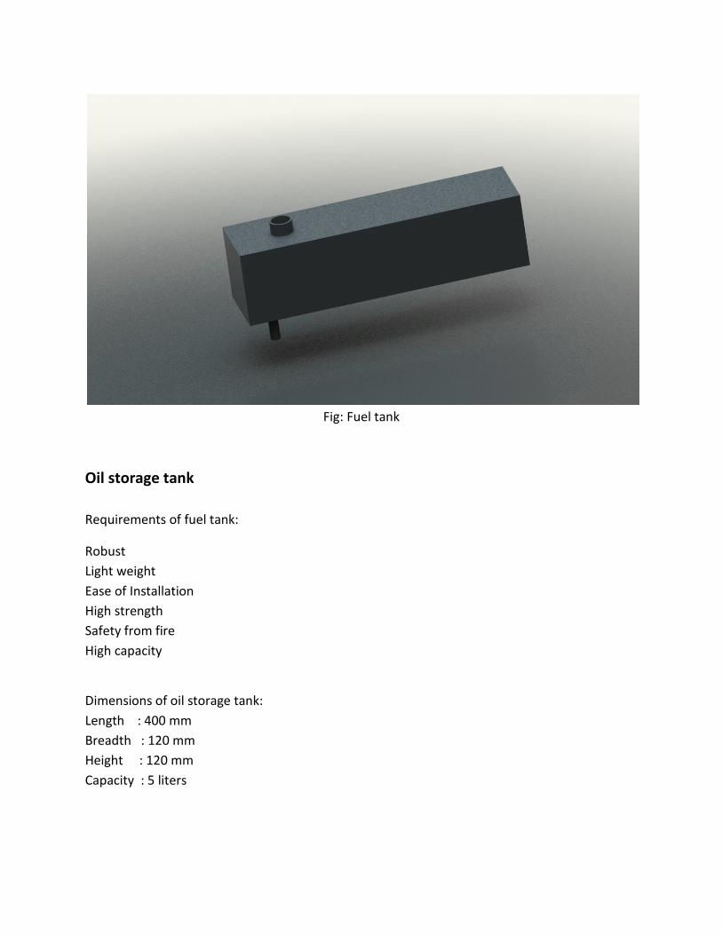
Fig: Fuel tank
Oil storage tank
Requirements of fuel tank:
Robust
Light weight
Ease of Installation
High strength
Safety from fire
High capacity
Dimensions of oil storage tank:
Length : 400 mm
Breadth : 120 mm
Height : 120 mm
Capacity : 5 liters
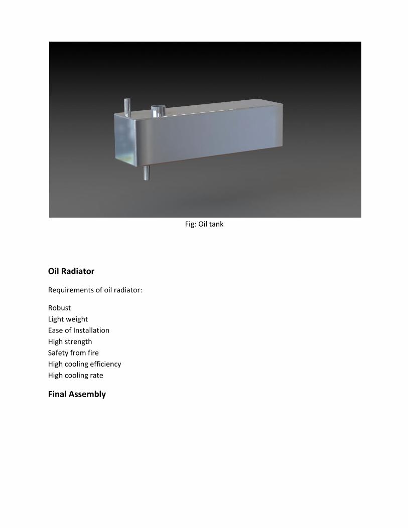
Fig: Oil tank
Oil Radiator
Requirements of oil radiator:
Robust
Light weight
Ease of Installation
High strength
Safety from fire
High cooling efficiency
High cooling rate
Final Assembly
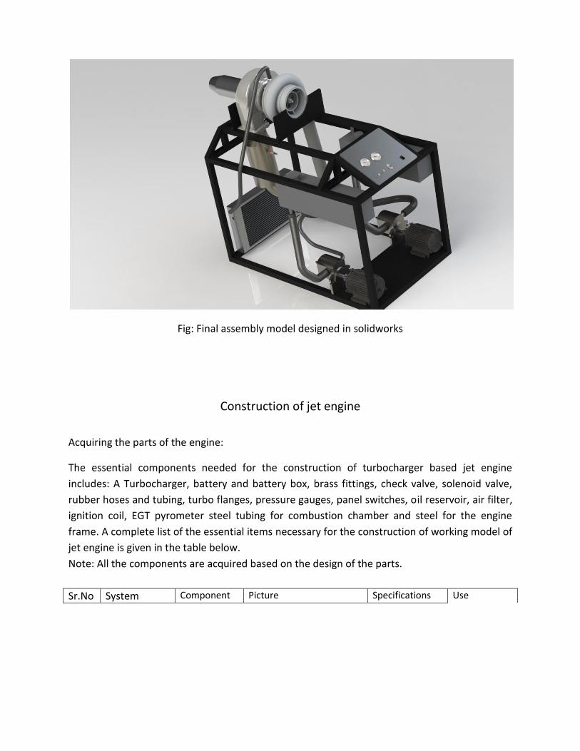
Fig: Final assembly model designed in solidworks
Construction of jet engine
Acquiring the parts of the engine:
The essential components needed for the construction of turbocharger based jet engine
includes: A Turbocharger, battery and battery box, brass fittings, check valve, solenoid valve,
rubber hoses and tubing, turbo flanges, pressure gauges, panel switches, oil reservoir, air filter,
ignition coil, EGT pyrometer steel tubing for combustion chamber and steel for the engine
frame. A complete list of the essential items necessary for the construction of working model of
jet engine is given in the table below.
Note: All the components are acquired based on the design of the parts.
Sr.No System Component Picture Specifications Use

1 Compression and expansion device
Turbocharger
Strakonice Czech Republic
Model: K36 3566 2521
Compression and expansion device
2 Fuel System Fuel pump
S. K. Industries Capacity: 5 Lpm Pressure: 20 bar
Pressurized pumping
3 Fuel Nozzle
Spartech India Ltd Capacity: 4 GPH Hollow cone spray
Fuel spraying device
4 Fuel Tank
Custom made Capacity: 5 Liters
Fuel storage
5 Fuel regulating circuit
Ball valve
S.K. Brass Fittings Std 0.5 inch brass ball valve
Fuel shut off valve (in case of disaster)
6 Hose and Fittings
S.K. Brass Fittings Std 0.5 inch brass connectors and fittings
Connecting components like oil tank to pump to hydraulic bearing
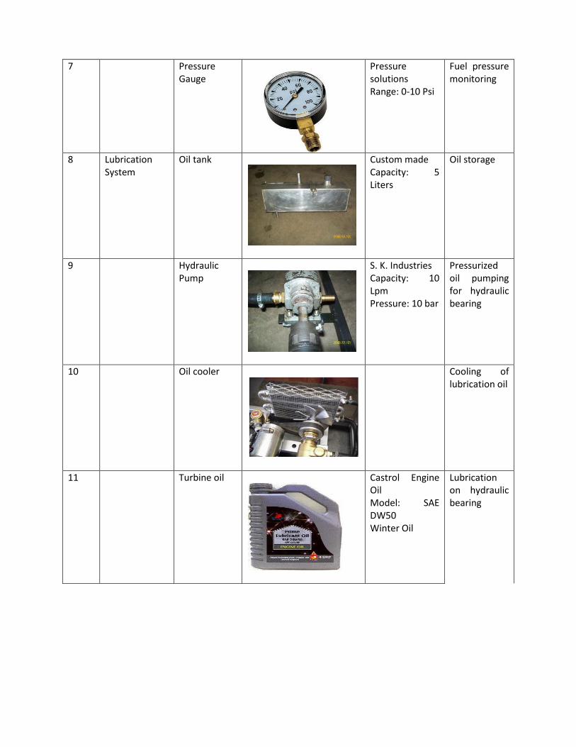
7 Pressure Gauge
Pressure solutions Range: 0-10 Psi
Fuel pressure monitoring
8 Lubrication System
Oil tank
Custom made Capacity: 5 Liters
Oil storage
9 Hydraulic Pump
S. K. Industries Capacity: 10 Lpm Pressure: 10 bar
Pressurized oil pumping for hydraulic bearing
10 Oil cooler
Cooling of lubrication oil
11 Turbine oil
Castrol Engine Oil Model: SAE DW50 Winter Oil
Lubrication on hydraulic bearing
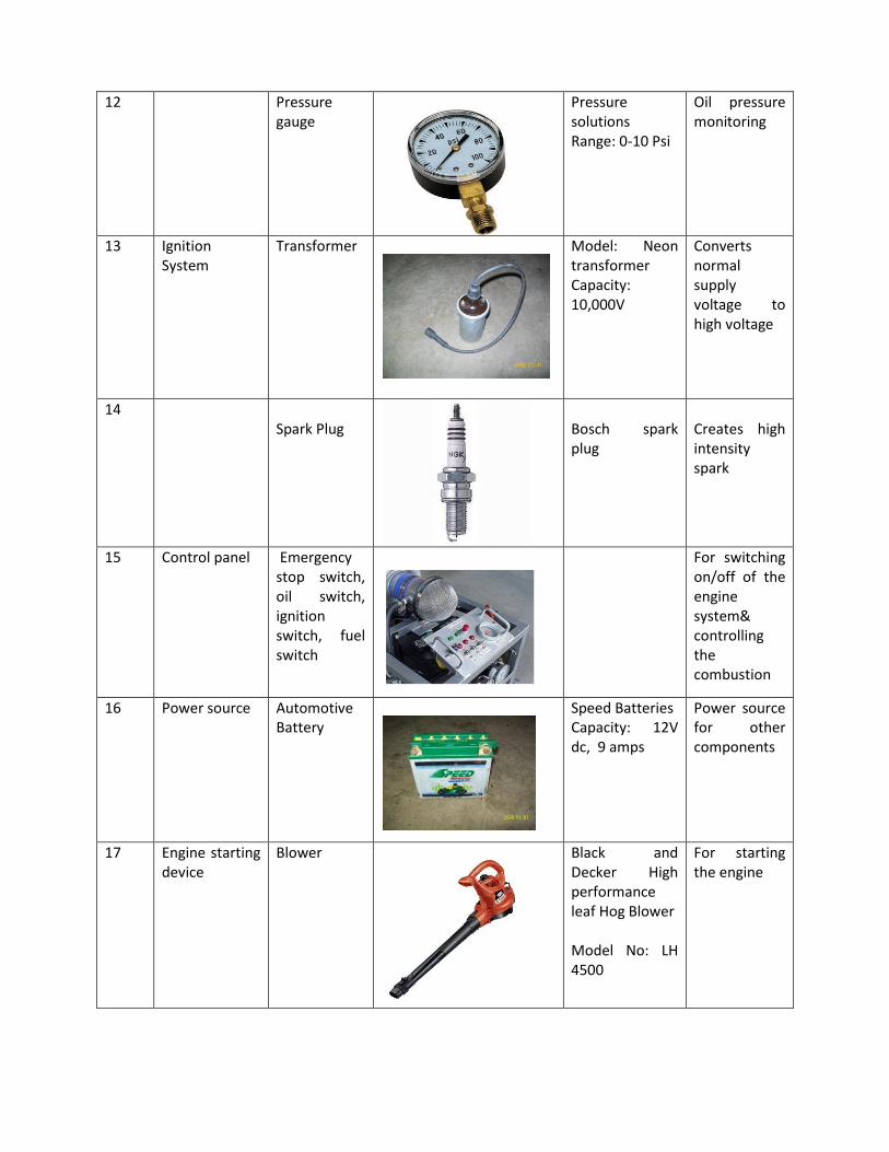
12 Pressure gauge
Pressure solutions Range: 0-10 Psi
Oil pressure monitoring
13 Ignition System
Transformer
Model: Neon transformer Capacity: 10,000V
Converts normal supply voltage to high voltage
14 Spark Plug
Bosch spark plug
Creates high intensity spark
15 Control panel Emergency stop switch, oil switch, ignition switch, fuel switch
For switching on/off of the engine system& controlling the combustion
16 Power source Automotive Battery
Speed Batteries Capacity: 12V dc, 9 amps
Power source for other components
17 Engine starting device
Blower
Black and Decker High performance leaf Hog Blower Model No: LH 4500
For starting the engine
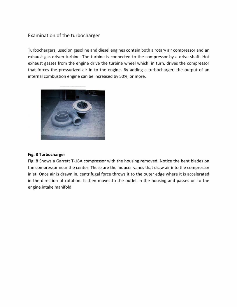
Examination of the turbocharger
Turbochargers, used on gasoline and diesel engines contain both a rotary air compressor and an
exhaust gas driven turbine. The turbine is connected to the compressor by a drive shaft. Hot
exhaust gasses from the engine drive the turbine wheel which, in turn, drives the compressor
that forces the pressurized air in to the engine. By adding a turbocharger, the output of an
internal combustion engine can be increased by 50%, or more.
Fig. 8 Turbocharger
Fig. 8 Shows a Garrett T-18A compressor with the housing removed. Notice the bent blades on
the compressor near the center. These are the inducer vanes that draw air into the compressor
inlet. Once air is drawn in, centrifugal force throws it to the outer edge where it is accelerated
in the direction of rotation. It then moves to the outlet in the housing and passes on to the
engine intake manifold.

Fig. 9 Compressor
Turbocharger compressor
The compressor on the turbocharger serves the same function as the compressor on the
turbojet engine. It is used to compress a large amount of air into a small space and increase
pressure. The compressor wheel turns at a very high speed; usually between 45,000 and
1,25,000 rpm. the larger truck turbochargers turn about 75,000 rpm. The compressor wheel is
usually made from and aluminum alloy. It does not run at a high temperature so aluminum
works fine. The compressed air exits the compressor into a diffuser. This is usually a casting that
increases in area so that the air will be slowed down and the pressure will increase.
The compressor end contains the impeller. It is usually an investment casting of aluminum
alloy. The blades neat the center are called the inducer vanes and are used to draw the air into
the compressor where the radial blades accelerate it. The air then passes into the snail shaped
housing called the diffuser.
Fig. 10
Turbine
The turbine

The turbine is located at the rear of the turbocharger inside a snail housing. The turbine is a
radial inflow design. The snail housing is designed to increase the velocity of the inflowing air so
that it strikes the turbine blades, at high velocity. The inflowing high speed air strikes the tips of
the blades near the outlet and is designed to exhaust the hot gases to the rear. Gas
temperature at this point is about 1800 deg. F. The turbine wheel is usually cast from hast alloy
or some other nickel alloy.
Fig. 11
Bearing
The Drive Shaft and Bearing
The turbine drives the compressor by means of a drive shaft, usually a very short, small
diameter shaft that is friction welded to the turbine wheel and bolted to the compressor. The
shaft runs through an aluminum bearing.
Most modern turbochargers use hydrodynamic bearings as shown in Fig. 11. This is an alloy
sleeve bearing with design tolerances that allow a layer of oil between the shaft and the
bearing. When the turbocharger is running, the oil supply is under pressure and the shaft rides
on a layer of oil and does not touch the alloy bearing. The shaft is suspended on a layer of oil.
The trust bearing on the turbine end rides on a layer of oil and is cooled by oil. The turbine end
bearing runs extremely hot, usually about 1,800 deg. F. Large quantities of oil must be
circulated to provide adequate cooling.
Construction of combustion chamber
Construction of the combustion chamber is the most time consuming and critical task because
the working and the satisfactory performance of the jet engine is completely dependent on the
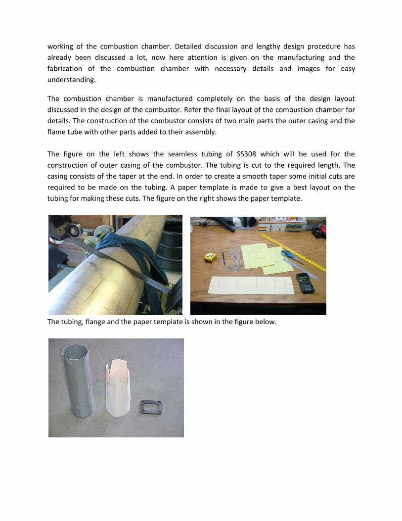
working of the combustion chamber. Detailed discussion and lengthy design procedure has
already been discussed a lot, now here attention is given on the manufacturing and the
fabrication of the combustion chamber with necessary details and images for easy
understanding.
The combustion chamber is manufactured completely on the basis of the design layout
discussed in the design of the combustor. Refer the final layout of the combustion chamber for
details. The construction of the combustor consists of two main parts the outer casing and the
flame tube with other parts added to their assembly.
The figure on the left shows the seamless tubing of SS308 which will be used for the
construction of outer casing of the combustor. The tubing is cut to the required length. The
casing consists of the taper at the end. In order to create a smooth taper some initial cuts are
required to be made on the tubing. A paper template is made to give a best layout on the
tubing for making these cuts. The figure on the right shows the paper template.
The tubing, flange and the paper template is shown in the figure below.
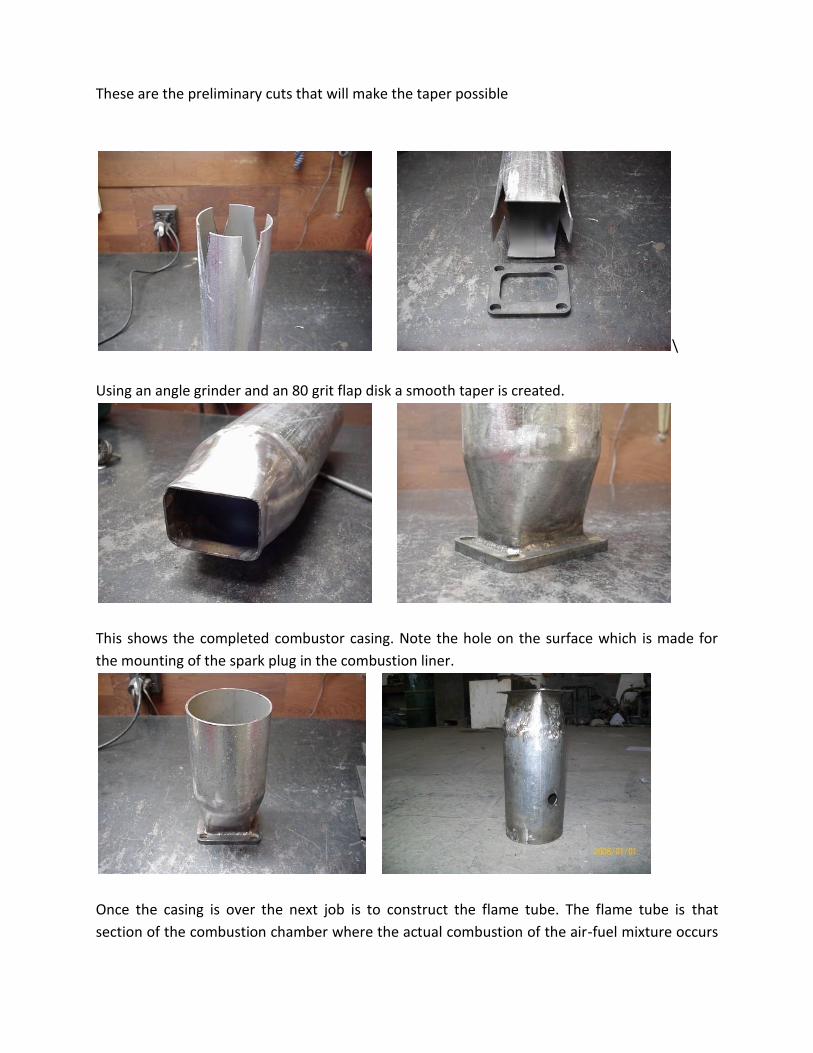
These are the preliminary cuts that will make the taper possible
\
Using an angle grinder and an 80 grit flap disk a smooth taper is created.
This shows the completed combustor casing. Note the hole on the surface which is made for
the mounting of the spark plug in the combustion liner.
Once the casing is over the next job is to construct the flame tube. The flame tube is that
section of the combustion chamber where the actual combustion of the air-fuel mixture occurs

thus the material of the liner needs to be of very high thermal resistance. SS310 seems to be a
good option. The SS310 seamless tubing of 1.5mm thickness is cut to the required length. The
image on the left shows the liner material being cut. The image on the right shows the drilling
operation on the liner to make the holes of necessary dimensions as per the design.
The completed liner is shown in the images below. The figure on the right side shows the flange
and the inner flare welded to the main liner.
All the necessary parts of the combustion chamber are depicted in the figure below. The image
clearly shows the liner, outer casing and the 90 degree bend. Along with these parts the other
parts are the swirl vanes, spray nozzle, spark plug and the copper pipe.
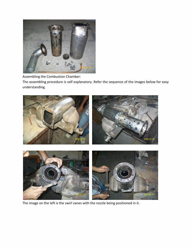
Assembling the Combustion Chamber:
The assembling procedure is self explanatory. Refer the sequence of the images below for easy
understanding.
The image on the left is the swirl vanes with the nozzle being positioned in it.

The copper pipe is goes through the 90 degree bend. The swirl vanes are then inserted in the
flare section.
This shows all the three flanges being bolted from outside.

The spark plug on the left is screwed in the liner from outside.
This shows the completed assembly of the combustion chamber. Note the copper tube coming
out of the pipe. This will be the inlet for the fuel.
The figure on the left is the PVC pipe that is fitted on the 90 degree pipe of the combustor. The
other end of this pipe will be press fitted to the compressor outlet.

The figure below shows the entire combustion chamber ready to be mounted directly on the
turbocharger.
Testing of combustion chamber:
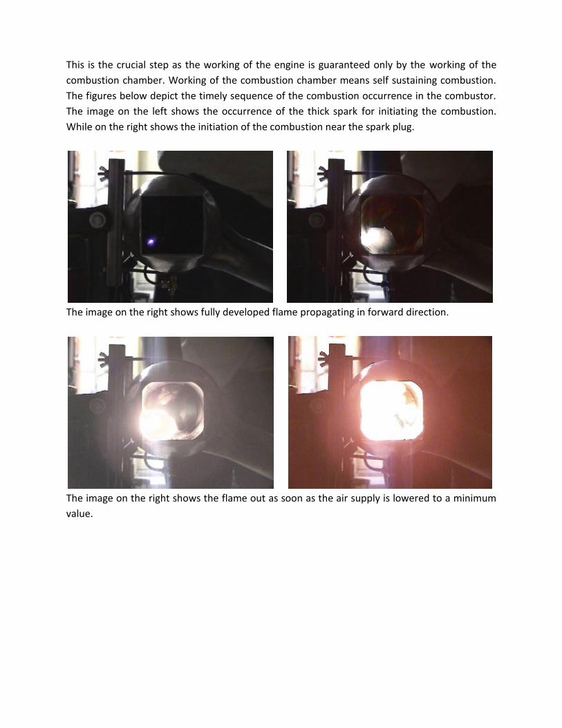
This is the crucial step as the working of the engine is guaranteed only by the working of the
combustion chamber. Working of the combustion chamber means self sustaining combustion.
The figures below depict the timely sequence of the combustion occurrence in the combustor.
The image on the left shows the occurrence of the thick spark for initiating the combustion.
While on the right shows the initiation of the combustion near the spark plug.
The image on the right shows fully developed flame propagating in forward direction.
The image on the right shows the flame out as soon as the air supply is lowered to a minimum
value.

Installing the engine’s subsystems
Jet engine test stand:
Turbojet engines operate at high temperatures and produce considerable thrust. A test stand
must be constructed in such a manner that it can be fastened to a solid anchor of some sort. A
welded Mild steel test stand of hollow square tube cross section of 0.5”×0.5” will support
engine at a reasonable working height and support it while running.
Some method must be used to mount the turbocharger to the test stand. The turbocharger
mounting is designed to take up the weight of the turbocharger and combustion chamber
assembly as well as to withstand the thrust produced while the engine operation. The turbo
must be secured so that it will not move when running.
For mounting the assembly two mounting straps are designed from mild steel plates see fig
below, one at the compressor end and other at the turbine end. The mounting at the turbine
end is secured by means of MS bolts and the other mounting is welded to the engine frame.

Mounting combustion chamber on Turbocharger
Having designed the combustion chamber based on the turbo flanges, mounting of the
combustion chamber should not be difficult. The combustor assembly that was constructed
earlier is simply positioned on the turbocharger. Below are the images of the turbocharger
depicting the compressor outlet and the turbine inlet flange.
The image below shows the mounting of the entire combustor on the turbocharger. The image
clearly illustrates the simplicity of the mounting procedure. The PVC pipe goes inside the
compressor outlet; on the other hand combustor’s flange is matched with the turbine flange,
both the flanges are bolted together by means of SS 10mm bolts.

Below is the image showing the bolted assembly of the turbine and the combustor flanges.
Construction and fabrication of the exhaust nozzle:
The turbine exhaust nozzle is manufactured from SS308 2mm seamless tubing. The nozzle is
manufactured completely on the design basis. Below is the image showing the step by step
construction of the exhaust nozzle. On the left is the 4mm thick flange of MS and seamless

tubing of SS308. Refer design of nozzle for detailed dimensions. The tapering section is
constructed in the similar way as that of the combustor casing, the figure on the right shows
the initial cuts made for the taper.
The figure on the right shows the required bend that is made by hammering out the cut taper.
While the figure on the right shows the welding of the joints at the taper
The completed nozzle is shown in the figure below.
Mounting the exhaust nozzle on the turbocharger:

The mounting of the nozzle on the turbo is achieved by series of the bolts on the turbo. The
turbo has 6 bolts of size 10mm symmetrically placed on the exhaust side. The nozzle flange
manufactured accordingly to fit on the turbo exhaust. Refer the image below.
The images below depicts the complete engine assembly consisting of turbocharger,
combustion chamber and the exhaust nozzle.
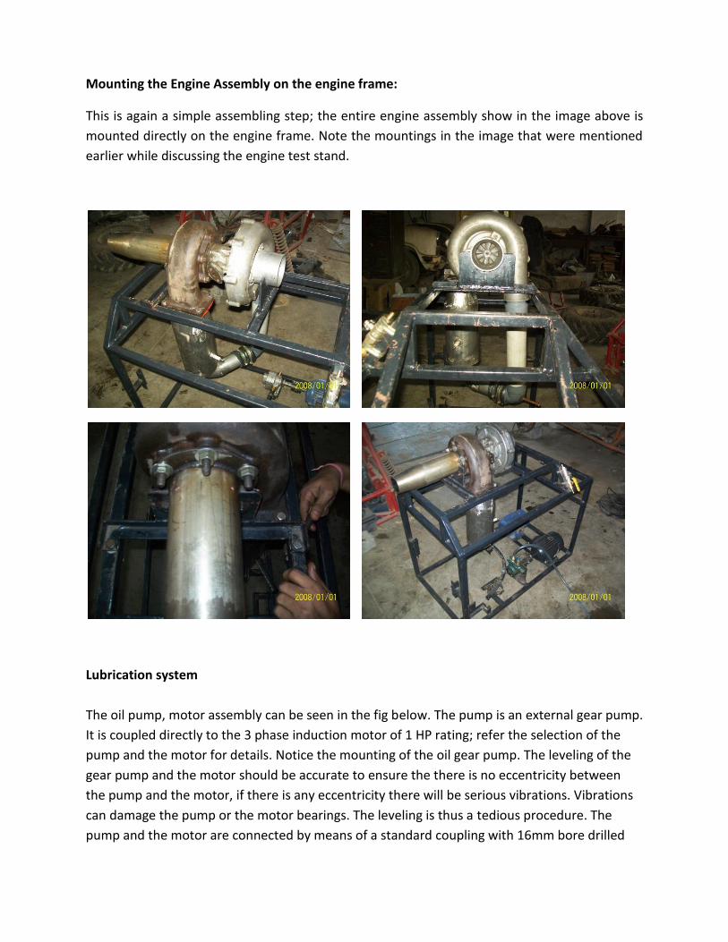
Mounting the Engine Assembly on the engine frame:
This is again a simple assembling step; the entire engine assembly show in the image above is
mounted directly on the engine frame. Note the mountings in the image that were mentioned
earlier while discussing the engine test stand.
Lubrication system
The oil pump, motor assembly can be seen in the fig below. The pump is an external gear pump.
It is coupled directly to the 3 phase induction motor of 1 HP rating; refer the selection of the
pump and the motor for details. Notice the mounting of the oil gear pump. The leveling of the
gear pump and the motor should be accurate to ensure the there is no eccentricity between
the pump and the motor, if there is any eccentricity there will be serious vibrations. Vibrations
can damage the pump or the motor bearings. The leveling is thus a tedious procedure. The
pump and the motor are connected by means of a standard coupling with 16mm bore drilled

on it. The oil goes into the turbocharger bearings under about 45lbs pressure and returns by
gravity.
The image below shows the mounting of the flanges for the turbocharger’s hydrostatic bearing.
the figure on the right also shows the ball valve for controlling the oil flow to the turbocharger.
The figure on the left shows the hoses mounted on the brass fittings, the image on the right
side depicts the oil tank, the oil hose from the turbo is connected to the oil tank without any
interference so that the oil from the turbo flows directly to the tank under the influence of
gravity.

Fuel pumping system
The fuel pump, motor assembly can be seen in the fig below. The pump is an internal gear
pump. It is coupled directly to the 3 phase induction motor of 1 HP rating; refer the selection of
the pump and the motor for details. This assembly is made in the similar way as that of the oil
pump and the motor with the same leveling procedure. Note that the internal gear pump here
has a different mounting than that of oil pump.
The image on the left shows the mounting of the fuel tank. The fuel tank is design to
accommodate 1 gallon of fuel (kerosene). The image on the right side shows the connection of
the fuel tank with the fuel pump inlet. The fuel from the fuel tank flows directly into the fuel
pump without any interference.

The fuel hose tee connection is made from the tee brass fitting shown below. The fuel hoses
are nylon impregnated fire resistant.
The left image shows the ball valve for controlling the fuel supply to the combustion chamber.
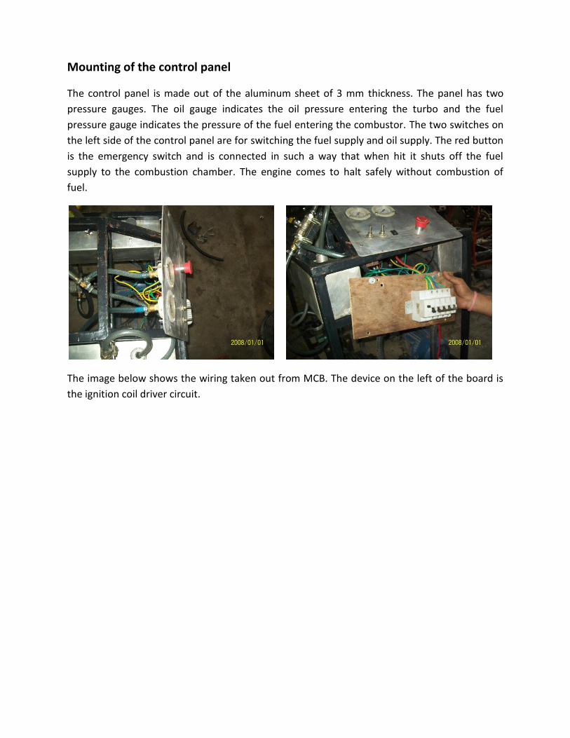
Mounting of the control panel
The control panel is made out of the aluminum sheet of 3 mm thickness. The panel has two
pressure gauges. The oil gauge indicates the oil pressure entering the turbo and the fuel
pressure gauge indicates the pressure of the fuel entering the combustor. The two switches on
the left side of the control panel are for switching the fuel supply and oil supply. The red button
is the emergency switch and is connected in such a way that when hit it shuts off the fuel
supply to the combustion chamber. The engine comes to halt safely without combustion of
fuel.
The image below shows the wiring taken out from MCB. The device on the left of the board is
the ignition coil driver circuit.

Electrical connections
The image on the left is the three phase wiring connected to the motor. The right side image
depicts the ignition coil
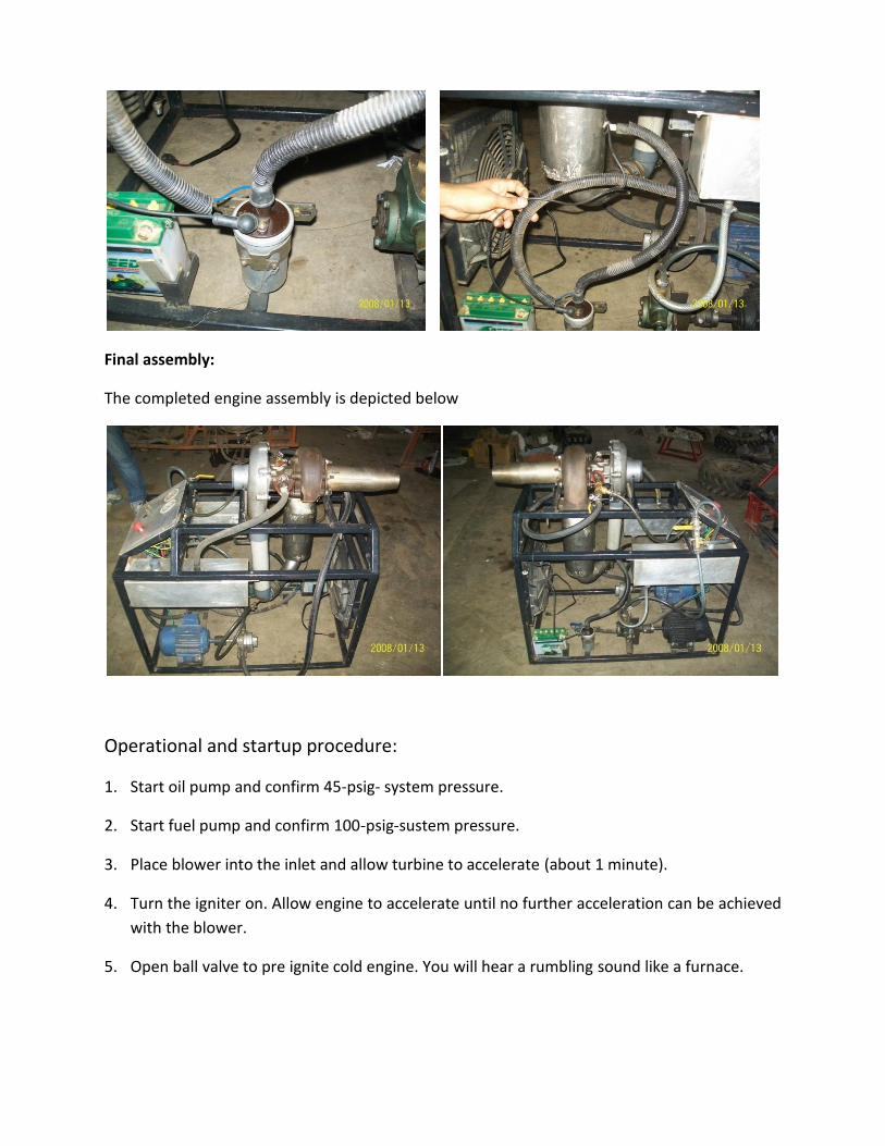
Final assembly:
The completed engine assembly is depicted below
Operational and startup procedure:
1. Start oil pump and confirm 45-psig- system pressure.
2. Start fuel pump and confirm 100-psig-sustem pressure.
3. Place blower into the inlet and allow turbine to accelerate (about 1 minute).
4. Turn the igniter on. Allow engine to accelerate until no further acceleration can be achieved
with the blower.
5. Open ball valve to pre ignite cold engine. You will hear a rumbling sound like a furnace.

6. Turn fuel idle valve on (25 pounds nozzle pressure). Confirm fuel ignition. Do not remove
blower yet.
7. If the turbine outlet temperature exceeds 1,100 deg. F. Shut fuel off immediately.
8. Allow engine to accelerate until it tries to pull the blower into the engine.
9. Remove blower from inlet turn igniter off.
10. Allow engine to accelerate to idle speed (approximately 25,000 rpm).
11. Open throttle to 80-100 psig for full power.
12. The engine can be accelerated, reduced, or idled with the fuel control. Combustion
temperature should be around 850-875 deg. F.
Appendices
Combustion systems
1: Introduction
The design of the gas turbine combustion system is a complex process involving fluid dynamics,
combustion and mechanical design. For many years the combustion system was much less
amenable to theoretical treatment than any other components of the gas turbine, and any
development programme required considerable amount of trial and error. With very high cycle
temperatures of modern gas turbines, mechanical design remains difficult and that enabled a
need for mechanical development programme. The rapidly increasing use of the computational
fluid dynamics (CFD) in recent years has had a major impact on the design process which has
increased the understanding of the complex flow and reducing the amount of trial and error
required.

The main purpose of this chapter is to show what are the problems faced in the process of
designing. The improvements made in one module of the design will have its effect on other
modules, thus a compromise has to be made on the number of conflicting requirements, which
will vary widely with different applications.
The most common fuels for the gas turbines are liquid petroleum distillates and natural gas and
the attention will be focused on the combustion systems suitable for these fuels.
In the combustion chamber design, the major goals to be achieved are high combustion
efficiency, reduction of visible smoke, reduction of oxides of nitrogen.
2: Operational requirements
The combustor is the critical component because it must operate reliably at extreme
temperatures, should provide a suitable temperature distribution at entry to the turbine, and
create minimum amount of pollutants over a long operating life.
A good design of the gas turbine will emphasize the importance of high component efficiency
and high cycle temperature. For combustion system which is one of the components of the gas
turbine, high component efficiency means high combustion efficiency and low pressure loss.
For calculation purposes the combustion efficiency is considered to 99% and a pressure loss of
2-8% of compressor delivery pressures. Effect of these losses on the overall efficiency is not as
pronounced as the inefficiencies in the turbo machinery.
Aircraft gas turbines face the problems associated with operating over a wide range of inlet
pressure and temperature within the working conditions of Mach number and altitude. A
typical sub-sonic aircraft will operate at a cruise altitude of 11000m, where the ambient
pressure and temperature are 0.227 bar and216.8K respectively as compared with the sea level
values of 1.013bar and 288.15k. thus the combustor has to operate at greatly reduced air
intensity and mass flow at high altitudes, while using the same air/fuel ratio as at sea level to
produce the appropriate value of the turbine inlet temperature. Atmospheric conditions may
change but the combustor must deal with these changes by continuously varying fuel flow
without allowing the engine to flameout or exceed the temperature limits.
Stationary land-based gas turbines have wider choice of fuels natural gas is the preferred fuel
for applications such as pipeline compression, power generation etc. If natural gas is not
available liquid fuels are most widely used. Gas turbines can also be designed for dual fuel

operation, with normal operation on natural gas and an option to switch to the natural gas for
short periods.
Advantages of liquid fuels over Gaseous fuels
1. Requires less space for storage.
2. Higher calorific value.
3. Easy control of consumption.
4. Absence of danger of spontaneous combustion.
5. Easy handling and transportation.
Disadvantages of Liquid fuels
1. Excess air needed for complete combustion.
2. Operating efficiency is less.
3. Requires complex fuel spray system and fuel pumping system which consumes power
and also adds to the overall weight of the engine.
4. Heavy spark is required to ignite the air fuel mixture which in turn requires high voltage
source for igniter.
Advantages of gaseous fuel over liquid fuels:
1. Better control of combustion.
2. Much less excess air is needed for complete combustion.
3. More efficiency of operation.
4. Cleanliness.
5. Gives economy of heat and higher temperature.
6. Does not require complex fuel spray a system, also use of the fuel pump is eliminated
since gaseous fuels are stored in pressure tanks under pressure.
7. High intensity spark is not required since air-fuel mixture is homogenous and is evenly
distributed throughout the combustion zone.
Disadvantages of gaseous fuels:
1. Requires the use of air tight containers for fuel storage.
2. Involves leakage problems.
3. Danger of spontaneous combustion.
4. Unavailability of natural gases.

3: Types of combustion systems
Combustion in a normal open-cycle gas turbine is a continuous process in which the fuel is
burned in the air supplied by the compressor, an electric spark is required only for initiating the
process and thereafter the flame must be self-sustaining. There can be wide variety of ways for
choosing a combustor configuration according to different requirements of aircraft and ground-
based units with respect to weight, volume and frontal area. This can result in widely different
solutions.
Comparison of various gas turbines and jet engines gives that, at present, three arrangements
of the combustion chambers are being practiced viz.
1. A large combustion chamber
2. Multiple chambers and
3. Annular chamber
A large single chamber is usually employed in the case of heavy industrial power plants where
space and weight are of secondary importance. Since space is not so important, relatively low
gas velocities can be used which tends towards higher combustion efficiency and low pressure
loss; further heavy sections can be incorporated at the critical sections, which if properly
designed gives long life and high operating temperatures without buckling.
The multiple chamber arrangement is of common practice for the aircraft applications as well
as for few stationary power plants or marine engines. Its main advantage is the ease with which
the desired total combustion chamber volume can be achieved.
The third type of the combustion chamber, the annular chamber consist of the annular passage
connecting the compressor delivery with the turbine nozzle, permitting the formation of
continuous sheet of the hot gases which flows from former to the latter. Inside this annular
chamber is supported the inner flame tube which in this case is also annular. Fuel is injected
into the inner annular chamber by series of nozzles located at the compressor end of the
chamber.
4: Some important factors affecting combustor design
The main factors influencing the design of the combustion chamber for the gas turbines are.
7. The temperature of the gases after the combustion must be comparatively low to suit the
highly stressed turbine materials.
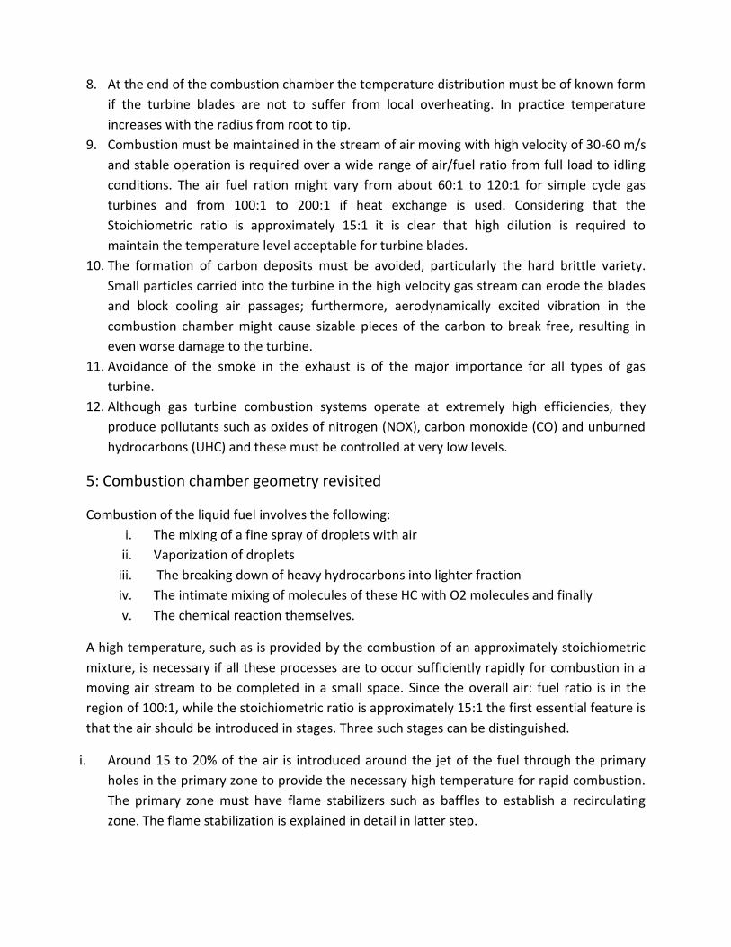
8. At the end of the combustion chamber the temperature distribution must be of known form
if the turbine blades are not to suffer from local overheating. In practice temperature
increases with the radius from root to tip.
9. Combustion must be maintained in the stream of air moving with high velocity of 30-60 m/s
and stable operation is required over a wide range of air/fuel ratio from full load to idling
conditions. The air fuel ration might vary from about 60:1 to 120:1 for simple cycle gas
turbines and from 100:1 to 200:1 if heat exchange is used. Considering that the
Stoichiometric ratio is approximately 15:1 it is clear that high dilution is required to
maintain the temperature level acceptable for turbine blades.
10. The formation of carbon deposits must be avoided, particularly the hard brittle variety.
Small particles carried into the turbine in the high velocity gas stream can erode the blades
and block cooling air passages; furthermore, aerodynamically excited vibration in the
combustion chamber might cause sizable pieces of the carbon to break free, resulting in
even worse damage to the turbine.
11. Avoidance of the smoke in the exhaust is of the major importance for all types of gas
turbine.
12. Although gas turbine combustion systems operate at extremely high efficiencies, they
produce pollutants such as oxides of nitrogen (NOX), carbon monoxide (CO) and unburned
hydrocarbons (UHC) and these must be controlled at very low levels.
5: Combustion chamber geometry revisited
Combustion of the liquid fuel involves the following:
i. The mixing of a fine spray of droplets with air
ii. Vaporization of droplets
iii. The breaking down of heavy hydrocarbons into lighter fraction
iv. The intimate mixing of molecules of these HC with O2 molecules and finally
v. The chemical reaction themselves.
A high temperature, such as is provided by the combustion of an approximately stoichiometric
mixture, is necessary if all these processes are to occur sufficiently rapidly for combustion in a
moving air stream to be completed in a small space. Since the overall air: fuel ratio is in the
region of 100:1, while the stoichiometric ratio is approximately 15:1 the first essential feature is
that the air should be introduced in stages. Three such stages can be distinguished.
i. Around 15 to 20% of the air is introduced around the jet of the fuel through the primary
holes in the primary zone to provide the necessary high temperature for rapid combustion.
The primary zone must have flame stabilizers such as baffles to establish a recirculating
zone. The flame stabilization is explained in detail in latter step.
ii. Some 30% of the total air is then introduced through secondary holes in the flame tube in
the secondary zone to complete the combustion. For high combustion efficiency, this air
must be introduced at the right points in the process, to avoid chilling of the flame locally
and drastically reducing the reaction rate in that neighborhood, and finally
iii. In the tertiary or the dilution zone the remaining air through tertiary holes is mixed with the
products of combustion to cool them down to the temperature required at the inlet to the
turbine. Sufficient turbulence must be promoted so that the hot and the cold streams are
thoroughly mixed to give the desired outlet temperature distribution, with no hot streaks
which would damage the turbine blades.
The necessary outline structure of the combustion chamber then appears as in fig. below,
yielding a typical annular form, with a central flame tube consisting of three zones surrounded
by outer casing.
6: Incomplete combustion & pressure losses
Having described the way in which the combustion process is accomplished, it is now possible
to see how incomplete combustion and pressure losses arise. This is simply due to the poor fuel
injector design leading to the fuel droplets being carried along the flame tube wall. Incomplete
combustion may be caused due to the local chilling of the flame at the points of the secondary
air entry. This can easily reduce the reaction rate to the point where some of the products into
which the fuel has decomposed are left in their partially burnt state, and the temperature at
the downstream end of the chamber is normally below at which the burning of these products
can be expected to take place. Since the lighter hydrocarbons in to which the fuel has
decomposed has the higher ignition temperature than the original fuel it is clearly difficult to
prevent some chilling from taking place, particularly if the space is limited and the and the
secondary air cannot be introduced gradually enough. If devices are used to increase the large
scale turbulence and so distribute the secondary air more uniformly throughout the burning
gases, the combustion efficiency will be improved but at the expense of the increased pressure
loss. A satisfactory compromise must somehow be reached.
Combustion chamber pressure is due to two distinct cases:
(1) Skin friction and turbulence &
(2) Rise in temperature due to combustion

The stagnation pressure loss associated with the latter often called the fundamental pressure
loss, arises because an increase in temperature implies a decrease in density and consequently
an increase in the velocity and the momentum of the stream. A pressure force ( p A ) must
be present to impart the increase in the momentum.
The pressure loss due to friction is found to be of very much higher- of the order of 20 inlet
dynamic heads, it is known as cold loss. Friction loss is so high due to the need of high scale
turbulence, turbulence of this king is created by the devices used to stabilize the flame e.g. swirl
vanes. In addition there is turbulence introduced by the jets in the secondary and the tertiary
air. The need for the good mixing of the secondary air with the burning gases has been
emphasized. Similarly good mixing of the dilution air to avoid the hot streaks in the turbine is
essential. In general the more effective the mixing the higher is the pressure loss. Here again a
compromise must be reached this time between the uniformity of the outlet temperature
distribution and the low pressure loss.
7: Some practical problems
We will briefly describe some of the problems which have not been mentioned but which are
none the less important. These are concerned with (1): flame tube cooling, (2): fuel injection,
(3): starting and ignition.
1. Flame tube cooling:
One problem which has assumed greater importance as permissible turbine inlet temperatures
have increased is that of cooling the flame tube. The tube receives energy by convection from
the hot gases and by radiation from the flame. It losses energy by convection to the cooler air
flowing along the outside surface and by radiation to the outer casing, but this loss is not
sufficient to maintain the tube wall at a safe temperature. A common practice is to leave
narrow annular gaps between overlapping sections of the flame tube, so that the film of the
cooling air is swept along the inner surface.
2. Fuel injection:
Most combustion systems employ the high pressure fuel systems in which the fuel is forced
through the small orifice to form a conical spray of the droplets in the primary zone. The fuel is
said to be atomized and the burner is often referred to as an atomizer. There will be a certain
minimum fuel pressure at which a fully developed spray will issue from the orifice. The spray
will consist of the droplets having wide range of the diameter, and the degree of the
atomization is often expressed in terms of mean droplet diameter. 50-100 microns is the order
of magnitude used in practice. The higher the supply pressure the smaller is the mean
diameter. If the droplets are too small they will not penetrate far enough into the air stream,
and if they are too large the evaporation time may be too long. The effective minimum supply
pressure is one that will provide the required degree of atomization.
3. Starting and Ignition:
Under normal operating conditions the gas turbine combustion is continuous and self-
sustaining. An ignition system however is required for starting, and the ignition and the starting
systems must be closely integrated. The first step in starting a gas turbine is to accelerate the
compressor to the speed that gives airflow capable of sustaining combustion: during the period
of acceleration the ignition system is switched on and the fuel is fed to the burners when the
rotational speed reached about 15-20% of the normal. An igniter is situated in the primary
zone of the flame tube. Once the flame is established the igniter is switched off. Engine
shutdown normally requires the engine to be brought back to idle followed by shutting off the
fuel; shutdowns from the full power be avoided because of the possibility of differential
expansion/ contraction leading to seal rubs or seizure of the rotor.