design of waste heat recovery system in a sponge iron plant
TRANSCRIPT
DESIGN OF WASTE HEAT RECOVERY SYSTEM IN A SPONGE
IRON PLANT
A thesis submitted in partial fulfillment of the Requirements for the degree of Bachelor of Technology
In
Chemical Engineering
by
Saurav Kumar Sahu Roll No. 107CH031
Under the guidance of
Dr. Shabina Khanam
DEPARTMENT OF CHEMICAL ENGINEERING
NATIONAL INSTITUTE OF TECHNOLOGY ROURKELA May, 2011

i
CERTIFICATE
This is to certify that the thesis entitled “Design of Waste Heat Recovery System in A Sponge
Iron Plant” being submitted by Saurav Kumar Sahu as an academic project in the Department
of Chemical Engineering, National Institute of Technology, Rourkela is a record of bonafide
work carried out by him under my guidance and supervision.
Place: Prof.Shabina Khanam
Date: Assistant Professor
Dept. of Chemical Engineering,
NIT Rourkela

ii
ACKNOWLEDGEMENT
I wish to express my sincere thanks and gratitude to Prof. Dr. Shabina Khanam (Project
Guide) for suggesting me the topic and providing me the guidance, motivation and
constructive criticism throughout the course of the project.
I also express my sincere gratitude to Prof. Dr. K.C.Biswal (HOD), Prof. Dr. R. K. Singh and
Prof. Dr. H.M. Jena (Project Coordinator), of Department of Chemical Engineering, National
Institute of Technology, Rourkela, for their valuable guidance and timely suggestions during
the entire duration of my project work, without which this work would not have been
possible. I am also grateful to Department, Chemical Engineering for providing me the
necessary opportunities for the completion of my project. I specially thank Mr Allada
Chidambaram for his help regarding theoretical studies and the authorities of Sri Mahavir
Ferro Alloys Pvt. Ltd for their plant data and valuable time.
Saurav Kumar Sahu
107CH031

iii
ABSTRACT
India is emerging as the leading producer of sponge iron among developing as well
industrially developed nations. Sponge iron is produced by direct reduction of iron ore (DRI
process) and is popular because of use of non-coking coal. The conventional blast furnace
process uses coking coal. The DRI process doesn‟t require coking coal and therefore is
advantageous.
In the present work waste heat recovery system is designed to integrate the heat of waste gas
in the sponge iron process. For this purpose a case study of typical sponge iron production
process is considered. The waste gas from a sponge iron plant exits at a temperature of
around 200-300C. A lot of sensible heat is lost with these gases. This heat is utilized to
preheat the air entering to kiln. Further, the waste gas at reduced temperature is used to cool
hot sponge iron which is previously carried out by water. Consequently, considerable energy
and water savings is achived which increases the efficiency of the process manifold. The
objective of this project is to design a suitable heat recovery system for above cases which
can efficiently remove the sensible heat and put it to use.
The annual savings upon installing this system was found to be around Rs.95.3 lakh. The
annual coal savings was calculated to be 620 tons, which is worth Rs.15.5 Lakh. The annual
water savings was calculated to be 1.2 million tonnes, which is worth Rs.83 Lakhs.
Keywords: Waste Heat, Recovery, Waste Heat Utilisation, Design

iv
CONTENTS
Acknowledgement ii
Abstract iii
Contents iv
List of Table viii
List of Figures x
1. Introduction 1
2. Literature Review
2.1 DRI Process of Sponge Iron making
2.1.1 Introduction
2.1.2 Raw Materials
2.1.3 Theory
2.1.4 Commercial Processes
2.1.4.1 SL/RN Process
2.1.4.2 Codir Process
2.1.4.3 Accar
2.1.4.4 TDR Process
2.1.4.5 Jindal
2.1.5 Advantages of DRI Process
2.2 Waste Heat Recovery
2.2.1 Waste Heat
2.2.2 Classification
2.2.3 High temperature heat recovery
2.2.4 Medium temperature heat recovery
2.2.5 Low temperature heat recovery
4
4
4
5
5
5
5
8
8
8
9
9
10
10
12
13
14
14

v
2.2.6 Benefits of Heat Recovery
2.2.7 Development of a Waste Heat Recovery System
2.3 Waste Heat Recovery Technologies
2.3.1 Heat Exchanger
2.3.1.1 Recuperators
2.3.1.2 Regenerators
2.3.2 Waste Heat Boilers
2.3.3 Heat Pipe
2.3.4 Factors affecting waste heat recovery feasibility
2.4 Utilisation of waste heat of flue gas is sponge iron plant
2.5 Conventional methods of heat recovery from stack gases
2.5.1 Feed Water Preheating
2.5.2 Organic Rankine Cycle
2.5.3 Gas-Gas heat exchangers
2.5.3.1 Plate Heat Exchanger
2.5.4 Direct Contact Heat Exchanger
2.6 Possible uses of waste heat
15
16
17
17
17
18
18
19
19
20
21
21
22
23
23
23
24
3. Problem Statement
3.1 Case Study
3.1.1 Feed Stream
3.1.2 Dust Settling Chamber
3.1.3 After-Burning Chamber
3.1.4 Waste Heat Boiler
3.1.5 Electrostatic Precipitator
25
25
25
25
26
26
26

vi
3.2 Flow Sheet
3.2.1 Process Description
3.3 Areas of interest for heat integration
3.3.1 Rotary Cooler
3.3.2 Stack Gases
27
28
29
29
29
4. Energy Conservation Measures
4.1 Potential areas for Heat Integration
4.2 Design Procedure
4.2.1 Duct
4.2.2 Air Preheater
4.2.3 Flue Gas-Water Heat Exchanger
4.2.4 Solid-Gas Heat Exchanger
4.2.5 Return Duct
4.2.6 Cost Estimation
4.2.6.1 Capital Cost
4.2.6.2 Operating Cost
4.2.6.3 Annual Savings
30
30
31
31
32
32
33
34
34
34
34
34
5. Results and discussion
5.1 Designed Equipment
5.1.1 Duct
5.1.2 Insulation
5.1.3 Air Preheater
5.1.4 Flue Gas Cooler
5.1.5 Solid Gas Heat Exchanger
5.1.6 Return Duct
36
36
36
38
39
40
41
41

vii
5.2 Cost Estimation
5.2.1 Capital Cost Estimation
5.2.2 Operating Cost Estimation
5.2.3 Total Annual Cost
5.2.4 Existing Capital Cost
5.2.5 Existing Operating Cost
5.2.6 Existing Total Annual Cost
5.2.7 Annual Savings
41
41
42
44
44
44
45
45
6. Conclusions 46
Bibliography 47
Appendix A: Design of Duct
Appendix B: Design of Air preheater
Appendix C: Design of Flue gas cooler
Appendix D: Design of solid gas heat exchanger
49
55
58
60
viii
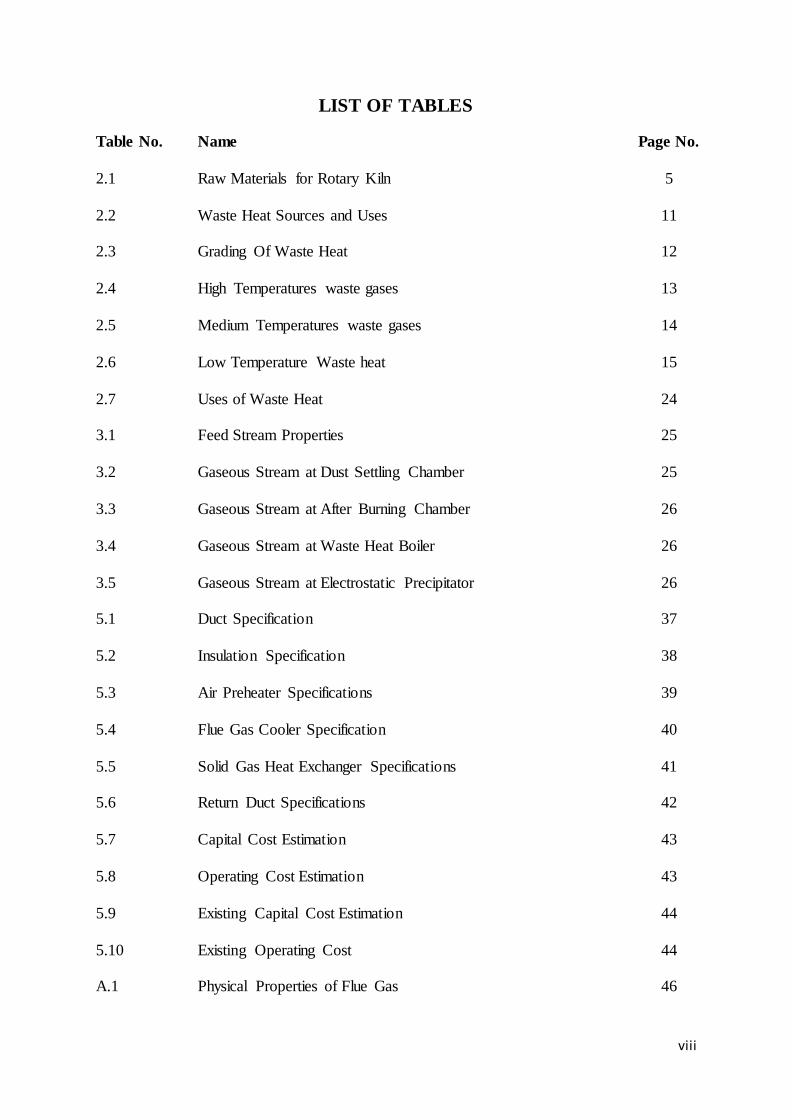
LIST OF TABLES
Table No. Name Page No.
2.1 Raw Materials for Rotary Kiln 5
2.2 Waste Heat Sources and Uses 11
2.3 Grading Of Waste Heat 12
2.4 High Temperatures waste gases 13
2.5 Medium Temperatures waste gases 14
2.6 Low Temperature Waste heat 15
2.7 Uses of Waste Heat 24
3.1 Feed Stream Properties 25
3.2 Gaseous Stream at Dust Settling Chamber 25
3.3 Gaseous Stream at After Burning Chamber 26
3.4 Gaseous Stream at Waste Heat Boiler 26
3.5 Gaseous Stream at Electrostatic Precipitator 26
5.1 Duct Specification 37
5.2 Insulation Specification 38
5.3 Air Preheater Specifications 39
5.4 Flue Gas Cooler Specification 40
5.5 Solid Gas Heat Exchanger Specifications 41
5.6 Return Duct Specifications 42
5.7 Capital Cost Estimation 43
5.8 Operating Cost Estimation 43
5.9 Existing Capital Cost Estimation 44
5.10 Existing Operating Cost 44
A.1 Physical Properties of Flue Gas 46

ix
A.2 Calculation of average U 47
A.3 Diameter Calculation 51
A.4 Net Expenses 52
A.5 Actual U & Outlet Temperature 53
A.6 Insulation Thickness~ Temperature Drop 54
A.7 Net Savings~ Thickness 54
B.1 Air Outlet Temperature 55
C.1 Mass & Energy Balance in Flue-Gas Cooler 58
D.1 Heat & Mass Balance in Solid-Gas Heat Exchanger 60
D.2 Calculation of Conductivity 61
D.3 Equivalent wall conductivity 62
D.4 Average Coefficient 63
D.5 Diameter and length of Solid-Gas Heat Exchanger 64
D.6 Pressure Drop in Solid Gas Heat Exchanger 64
x
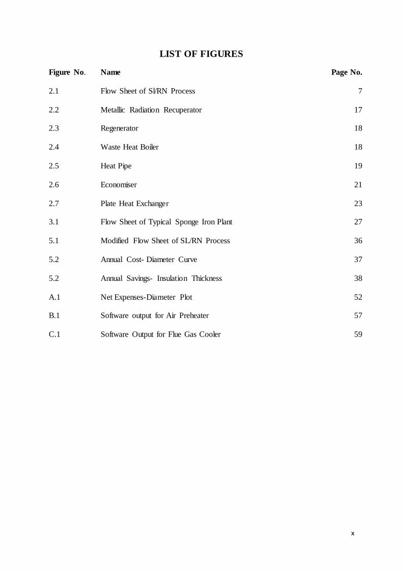
LIST OF FIGURES
Figure No. Name Page No.
2.1 Flow Sheet of Sl/RN Process 7
2.2 Metallic Radiation Recuperator 17
2.3 Regenerator 18
2.4 Waste Heat Boiler 18
2.5 Heat Pipe 19
2.6 Economiser 21
2.7 Plate Heat Exchanger 23
3.1 Flow Sheet of Typical Sponge Iron Plant 27
5.1 Modified Flow Sheet of SL/RN Process 36
5.2 Annual Cost- Diameter Curve 37
5.2 Annual Savings- Insulation Thickness 38
A.1 Net Expenses-Diameter Plot 52
B.1 Software output for Air Preheater 57
C.1 Software Output for Flue Gas Cooler 59
1
CHAPTER 1
INTRODUCTION
Sponge iron is the metallic form of iron produced from reduction of iron oxide below
the fusion temperature of iron ore (1535 oC) by utilizing hydrocarbon gases or carbonaceous
fuels as coal. The reduced product having high degree of metallisation exhibits a „honeycomb
structure‟, due to which it is named as sponge iron. As the iron ore is in direct contact with
the reducing agent throughout the reduction process, it is often termed as direct reduced iron
(DRI). Sponge iron is produced primarily both by using non-coking coal and natural gas as
reductant and therefore classified as coal based and gas based process respectively. Due to a
promising availability of coal, the coal based sponge iron plants share the major amount of its
production. At present, there are 118 large and small sponge iron plants operating in India,
amongst them only 3 are natural gas based and the remaining 115 plants are coal based.
With the availability of raw materials, high demand of sponge iron and less payback
period, sponge iron industry has emerged as a profitable venture. However, due to lack of
proper integration techniques, non-optimal process parameters, high energy consumption and
old running process technology, the industry are facing a setback in market. Further, it is seen
that much of the heat generated in the process is lost without being recovered due to lack of
heat recovery options. Thus the energy conservation in sponge iron plants has also sought the
attention of many investigators. Eriksson et al studied on the energy survey of sponge iron
process and showed that the process is 40% energy efficient and the major loss is through
exhaust gases [6]. Energy efficiency is defined as the energy needed for the reduction
reactions compared to the energy added to the system. Biswas et al. found that 10-12 %
energy can be saved by controlled axial and radial air injection, leading to efficient
combustion and improved heat transfer thus reducing waste gas temperatures [2]. Jena et al.
worked on the kiln data at the production capacity of 350 tpd, OSIL and showed that the

2
thermal efficiency of the process is 51.315% [7]. Considerable amount of heat is lost in the
waste gas which is about 33% of the heat generated in the kiln. The above fact has also been
reiterated by many other investigators [1],[5].
Moreover, waste heat recovery systems developed in the past depend on the quality of
heat which is mainly temperature of the waste streams. Waste heat boilers have been
successfully installed and used in different industries. They work on the principle of team-
Rankine Cycle. Installation of waste heat boilers needs high quality heat sources. The
temperature of the waste stream needs to be around C. For low temperature heat sources,
Organic-Rankine cycle based Power generation systems have been developed. These require
a source temperature of around C. In European countries, building heating systems have
been developed based on waste heat from household and industrial sources. Other waste heat
utilisation systems include Absorption/Adsorption refrigeration systems.
All the above mentioned systems have got inefficiencies and may not be applicable to
sponge-iron industries. Steam Rankine cycle needs high temperature sources. In a sponge
iron plant, high temperature waste sources are unavailable and therefore this system can‟t be
applied here. Organic Rankine cycle is based boiler is costly and inefficient. The source
temperature requirement of C renders this system unfit for the current system. Other
systems like Absorption/Adsorption refrigeration systems have been tested. These systems,
being costly and having large payback period, are not suitable for small scale plants.
Therefore, the conventional heat recovery systems can‟t be applied to sponge iron plants.

3
Based on above discussion it is found that a fresh look is required on sponge iron
process to propose the new design with integration of energy. For this purpose following
objectives are to be achieved:
1. To identify the possible areas of sponge iron process where energy is available
and can be utilized in the process.
2. To design suitable waste heat recovery systems for sponge iron process using the
possible areas
3. To perform economic analysis of the modified design for sponge iron process
based on capital investment, coal consumption, water requirement, energy
consumption, total profit, payback period, etc.

4
CHAPTER 2
LITERATURE REVIEW
2.1 DRI PROCESS OF SPONGE IRON MAKING
2.1.1 Introduction
Direct Reduced Iron, also called Sponge Iron, is produced by direct reduction of iron
ore by a reducing gas produced from coal or natural gas. This gas is mainly Carbon
Monoxide gas. The process is known as direct reduction because iron ore is reduced in solid
state itself. Iron ore doesn‟t melt [13]. The conventional route for making steel consists of
sintering or pelletization plants, coke ovens, blast furnaces, and basic oxygen furnaces. Such
plants require high capital expenses and raw materials of stringent specifications. Coking coal
is needed to make a coke strong enough to support the burden in the blast furnace. Integrated
steel plants of less than one million tons annual capacity are generally not economically
viable. The coke ovens and sintering plants in an integrated steel plant are polluting and
expensive units.Direct reduction, an alternative route of iron making, has been developed to
overcome some of these difficulties of conventional blast furnaces. DRI is successfully
manufactured in various parts of the world through either natural gas or coal-based
technology. Iron ore is reduced in solid state at 800 to 1,050 °C (1,472 to 1,922 °F) either by
reducing gas (H2+CO) or coal. The specific investment and operating costs of direct
reduction plants are low compared to integrated steel plants and are more suitable for many
developing countries where supplies of coking coal are limited.

5
2.1.2 Raw Materials
The raw material and its sizes used for sponge iron process are shown in Table 2.1.
Table 2.1: Raw Materials for Rotary Kiln
Material Type
Iron-Ore 5-18 mm
Coal 3-20 mm
Dolomite 2-06 mm
Air -
2.1.3 Theory
The theory of Direct Reduction process is very similar to the conventional process. Carbon
from coal is partially oxidised to Carbon Monoxide. Carbon Monoxide then reduces Iron ore
to produce Iron. The reactions can be shown as:
2.1.4 Commercial Processes:
The important commercial processes available are:- SL/RN, Codir, Accar, TDR & Jindal [3].
These are discussed in the following paragraphs.
2.1.4.1 SL/RN Process
Iron ore, coal and dolomite are sized and screened to have a proper size.The raw
materials are charged into the rotary kiln with the help of conveyor.

6
Compressed air is injected into the rotary kiln at various places with the help of
blowers. Dampers are used to control the flow rate of air.
Half of the coal is charged with iron ore charge. After coming in contact with air, it
produces CO n CO2 gases. The exothermic reactions increase temperature of coal and
bring it to reaction temperature. The rest of the coal is charged from the discharge
end. This reacts with CO2 to produce CO which acts as the reducing agent for Iron
Ore. Iron and CO2 are progressively formed.The rotary kiln is kept at a slant of -
which causes the materials to flow under gravity.
Limestone and dolomite are added as fluxing agents which react with the gangue
materials to produce slag.
The residence time of iron ore inside the kiln is about 10 hours. During this time, iron
ore is optimally reduced. Hot sponge iron along with semi burnt coal is discharged at
the discharge end. After being discharged, the materials enter a rotary cooler where
water is sprayed over the cooler and the temperature is brought down to about 1 C.
The products, after cooling, need to be separated into Iron, char and other non-
magnetic impurities. The iron particles are separated from char and other non-
magnetic impurities using electromagnetic separation.
The products are screened into different sizes and sent to storage. The gases out of the
rotary kiln are burnt in a chamber to ensure that CO is negligibly present. The gases,
at a temperature of 1 C, enter the waste heat boiler and then E P from where they
are routed to the stack at a temperature of - C.

7
The Flow-Sheet for SL/RN Process is shown in figure 2.1 [20]
Fig. 2.1:- Flow Sheet of SL/RN Process

8
2.1.4.2 Codir Process
Codir stands for Coal Ore Direct Reduction process
It is very similar to SL/RN Process with minor modifications.
The coal size range is very coarse, which is a unique feature of Codir (5-35mm). Coal
is counter-currently injected into the rotary kiln.
The air inlets are positioned towards the inlet end of rotary kiln.
Codir coolers use direct mist of water inside the cooler.
2.1.4.3 Accar
This stands for Allis-Chalmers Controlled Atmospheric Reduction.
The process is similar to Sl/Rn & Codir Process.
The fundamental difference is that, the reductant used in this case is a mixture of
coal+ oil or coal+ natural gas.
Oil/gas is injected directed in radial ports, symmetrically arranged in equally spaced
rows.
The injection is maintained in such a manner that, when the ports are under charge,
oil/gas is injected and when the ports are over the bed, air is injected.
The advantages are higher carbon content, high degree of metallisation, lower energy
consumption, lower operating temperatures etc.
2.1.4.4 TDR Process
This stands for TISCO Direct Reduction process and was developed in India.
Only Non-Coking coal is used and reductant and fuel oil is used only for kiln
preheating.

9
Coal used is of a specified size range and injected from both sides.
Dolomite is used in a specific size range.
Provision for radial and axial injection of air exists.
Rotary kiln has a diameter of 3.75 m and length of 72m. inclination is 1.432 .
2.1.4.5 Jindal
This process was developed by Jindal Strips Ltd.
The unique feature is that 55-60% coal is injected from discharge end and rest with
ore injection.
The C/Fe ration is around 0.42-0.44.
Coal up to 30% ash content is successfully used.
Blast furnace gas has been used in this process and has resulted in better reduction.
Steam is produced by utilisation of waste heat.
The Char and coal washery rejects are used in fluidised bed combustion boiler and
results in better waste heat recovery.
2.1.5 Advantages of DRI process:
The energy requirements of a sponge iron plant are much lesser than conventional
Blast Furnace plants.
The process doesn‟t require coking coal or coke.
The product Hot Briquetted iron is a compact form of DRI designed for ease of
transportation.
The percentage of iron is generally more than pig iron.

10
The operating costs are low too.
2.2 WASTE HEAT RECOVERY
Captured and reused waste heat is an emission free substitute for costly purchased fuels or
electricity. Numerous technologies are available for transferring waste heat to a productive
end use. No matter, anywhere from 513 quadrillion Btu/yr of waste heat energy remains
unrecovered as a consequence of industrial manufacturing. One has to investigate industrial
waste heat recovery practices, opportunities, and barriers in order to identify technology
research, development, and demonstration (RD&D) needed to enable further recovery of
industrial waste heat losses. Key opportunities are available in optimizing existing systems,
developing technologies for chemically corrosive systems, recovering heat from non-fluid
heat sources, and recovering low temperature waste heat.
Observed trends are:
Waste heat recovery systems are frequently implemented, but constrained by factors
such as temperature limits and costs of recovery equipment.
Most unrecovered waste heat is at low temperatures.
There are certain industrial subsectors where heat recovery is less common, due to
factors such as heat source‟s chemical composition and the economies of scale
required for recovery.
Losses from non-traditional waste heat sources are difficult to recover, but significant.
2.2.1 Waste Heat
Waste heat is heat generated in a process by way of fuel combustion or chemical reaction,
which is then “dumped” into the environment and not reused for useful and economic

11
purposes. The essential fact is not the amount of heat, but rather its “value”. Typical sources
of waste heat and recovery options are listed in Table 2.2.
Table 2.2:- Waste Heat Sources and Uses
Waste Heat Sources Uses for Waste Heat
Combustion Exhausts:
Cement kiln
Glass melting furnace
Aluminum reverberatory furnace
Boiler
• Process offgases:
Steel electric arc furnace
Aluminum reverberatory furnace
• Cooling water from:
Furnaces
Air compressors
Internal combustion engines
• Conductive, convective, and radiative losses from equipment:
HallHèroult cells
• Conductive, convective, and radiative losses from heated
products:
Hot cokes
Blast furnace slags
• Combustion air preheating
• Boiler feedwater preheating
• Load preheating
• Power generation
• team generation for use in:
power generation
mechanical power
process steam
• pace heating
• Water preheating
• Transfer to liquid or gaseous process streams
12
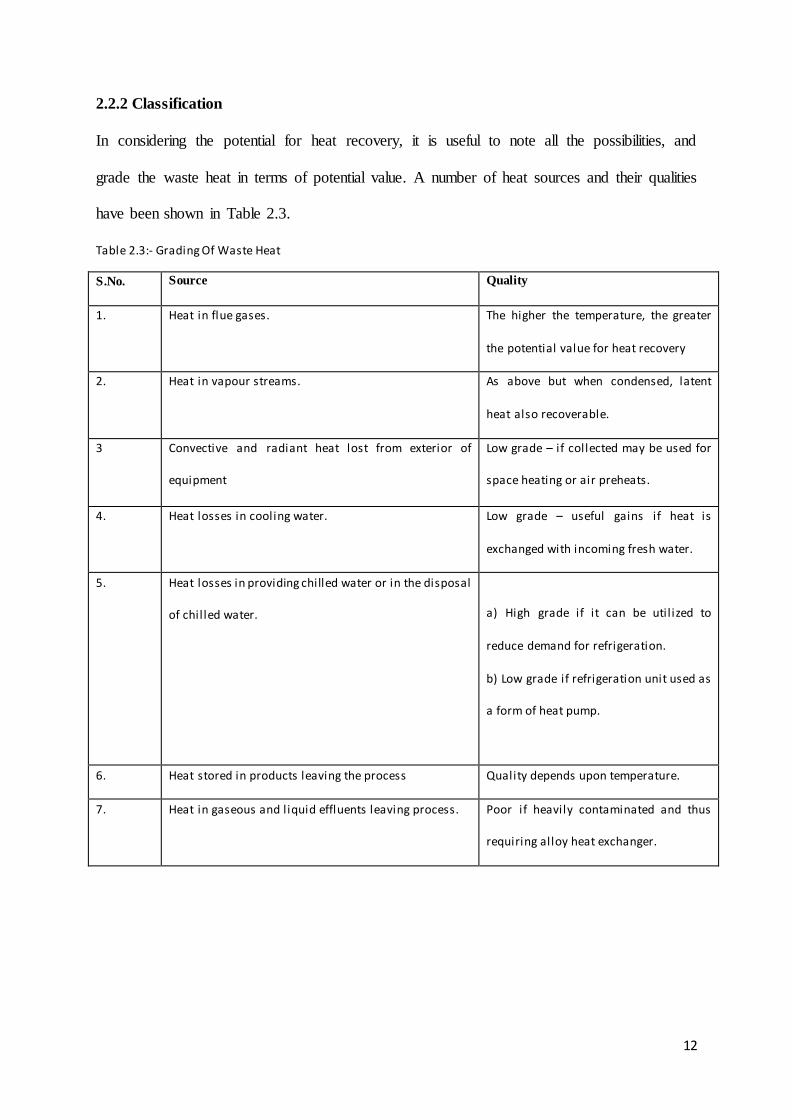
2.2.2 Classification
In considering the potential for heat recovery, it is useful to note all the possibilities, and
grade the waste heat in terms of potential value. A number of heat sources and their qualities
have been shown in Table 2.3.
Table 2.3:- Grading Of Waste Heat
S.No. Source Quality
1. Heat in flue gases. The higher the temperature, the greater
the potential value for heat recovery
2. Heat in vapour streams. As above but when condensed, latent
heat also recoverable.
3 Convective and radiant heat lost from exterior of
equipment
Low grade – if collected may be used for
space heating or air preheats.
4. Heat losses in cooling water. Low grade – useful gains if heat is
exchanged with incoming fresh water.
5. Heat losses in providing chilled water or in the disposal
of chil led water.
a) High grade if it can be util ized to
reduce demand for refrigeration.
b) Low grade if refrigeration unit used as
a form of heat pump.
6. Heat stored in products leaving the process Quality depends upon temperature.
7. Heat in gaseous and liquid effluents leaving process. Poor if heavily contaminated and thus
requiring alloy heat exchanger.
13
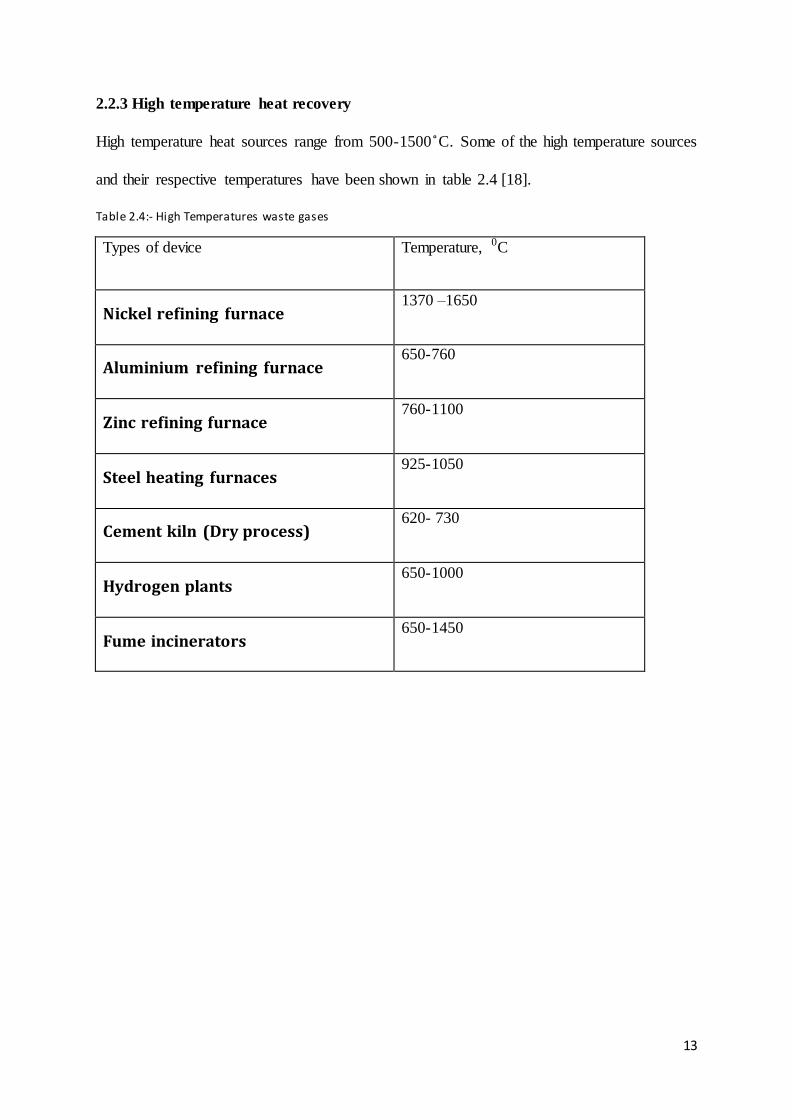
2.2.3 High temperature heat recovery
High temperature heat sources range from 500-1500 C. Some of the high temperature sources
and their respective temperatures have been shown in table 2.4 [18].
Table 2.4:- High Temperatures waste gases
Types of device Temperature, 0C
Nickel refining furnace 1370 –1650
Aluminium refining furnace 650-760
Zinc refining furnace 760-1100
Steel heating furnaces 925-1050
Cement kiln (Dry process) 620- 730
Hydrogen plants 650-1000
Fume incinerators 650-1450

14
2.2.4 Medium temperature heat recovery
Medium temperature heat sources have their temperatures in the range of 200-600 C. A few
medium temperature heat sources have been shown in table 2.5 [18].
Table 2.5:-Medium Temperatures waste gases
Type of Device Temperature, o
C
Steam boiler exhausts 230-480
Gas turbine exhausts 370-540
Reciprocating engine exhausts 315-600
Heat treating furnaces 425 – 650
Drying and baking ovens 230 – 600
Catalytic crackers 425 – 650
2.2.5 Low temperature heat recovery
Low temperature heat sources have their temperatures in the range of 30-250 C. A few low
temperature heat sources have been shown in table 2.6 [18].

15
Table 2.6:-Low Temperature Waste heat
Source Temperature, o
C
Process steam condensate 55-88
Cooling water from:
Furnace doors
32-55
Bearings 32-88
Welding machines 32-88
Air conditioning and refrigeration
condensers
32–43
Hot processed liquids 32-232
Hot processed solids 93-232
2.2.6 Benefits of Waste Heat Recovery
Benefits of „waste heat recovery‟ can be broadly classified in two categories:
Direct Benefits:
Recovery of waste heat has a direct effect on the efficiency of the process. This is reflected
by reduction in the utility consumption & costs, and process cost.

16
Indirect Benefits:
a) Reduction in pollution: A number of toxic combustible wastes such as carbon
monoxide gas, sour gas, etc, releasing to atmosphere if/when burnt in the incinerators
serves dual purpose i.e. recovers heat and reduces the environmental pollution levels.
b) Reduction in equipment sizes: Waste heat recovery reduces the fuel consumption,
which leads to reduction in the flue gas produced. This results in reduction in
equipment sizes of all flue gas handling equipment such as fans, stacks, ducts,
burners, etc.
c) Reduction in auxiliary energy consumption: Reduction in equipment sizes gives
additional benefits in the form of reduction in auxiliary energy consumption like
electricity for fans, pumps etc. [18].
2.2.7 Development of a Waste Heat Recovery System
Understanding the process is essential for development of Waste Heat Recovery system. This
can be accomplished by reviewing the process flow sheets, layout diagrams, piping
isometrics, electrical and instrumentation cable ducting etc. [8],[18].
Detail review of these documents will help in identifying:
a) Sources and uses of waste heat
b) Upset conditions occurring in the plant due to heat recovery
c) Availability of space
d) Any other constraint, such as dew point occurring in an equipment etc.

17
2.3 WASTE HEAT RECOVERY TECHNOLOGIES
Methods for waste heat recovery include transferring heat between gases and/or liquids (e.g.,
combustion air preheating and boiler feed-water preheating), transferring heat to the load
entering furnaces (e.g., batch/cullet preheating in glass furnaces), generating mechanical
and/or electrical power, or using waste heat with a heat pump for heating or cooling facilities.
Some of the equipment for the purpose is as follows [8], [18].
2.3.1 Heat Exchangers
Heat exchangers are most commonly used to transfer heat from combustion exhaust gases to
combustion air entering the furnace. Since preheated combustion air enters the furnace at a
higher temperature, less energy must be supplied by the fuel. Typical technologies used for
air preheating include Recuperators, furnace regenerators, burner regenerators, rotary
regenerators, and passive air preheaters.
2.3.1.1 Recuperators
Recuperators recover exhaust gas waste heat in
medium to high temperature applications such as
soaking or annealing ovens, melting furnaces,
afterburners, gas incinerators, radiant tube burners,
and reheat furnaces [14]. Recuperators can be based
on radiation, convection, or combinations of both.
Recuperators are constructed out of either metallic or
ceramic materials. A typical recuperator is shown in
Fig.2.2.
Fig. 2.2:- Metallic Radiation Recuperator
18
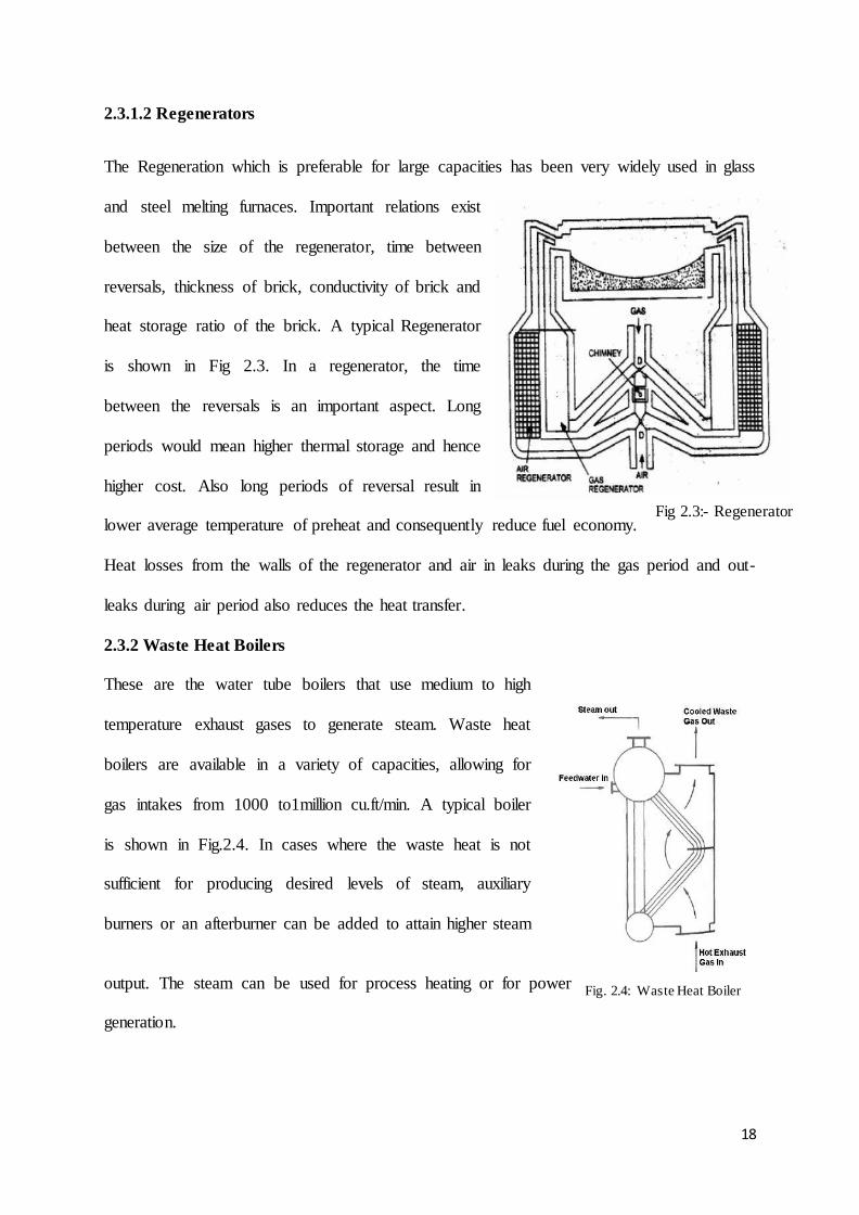
2.3.1.2 Regenerators
The Regeneration which is preferable for large capacities has been very widely used in glass
and steel melting furnaces. Important relations exist
between the size of the regenerator, time between
reversals, thickness of brick, conductivity of brick and
heat storage ratio of the brick. A typical Regenerator
is shown in Fig 2.3. In a regenerator, the time
between the reversals is an important aspect. Long
periods would mean higher thermal storage and hence
higher cost. Also long periods of reversal result in
lower average temperature of preheat and consequently reduce fuel economy.
Heat losses from the walls of the regenerator and air in leaks during the gas period and out-
leaks during air period also reduces the heat transfer.
2.3.2 Waste Heat Boilers
These are the water tube boilers that use medium to high
temperature exhaust gases to generate steam. Waste heat
boilers are available in a variety of capacities, allowing for
gas intakes from 1000 to1million cu.ft/min. A typical boiler
is shown in Fig.2.4. In cases where the waste heat is not
sufficient for producing desired levels of steam, auxiliary
burners or an afterburner can be added to attain higher steam
output. The steam can be used for process heating or for power
generation.
Fig 2.3:- Regenerator
Fig. 2.4: Waste Heat Boiler
19
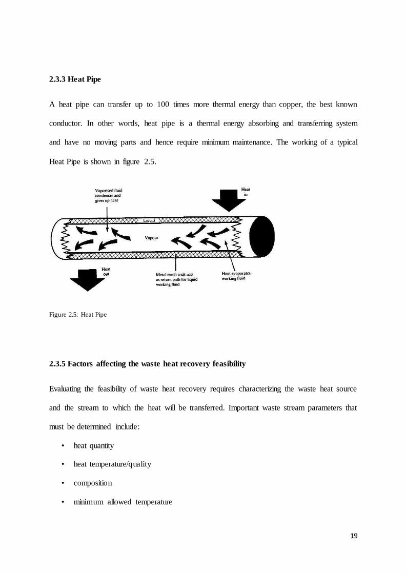
2.3.3 Heat Pipe
A heat pipe can transfer up to 100 times more thermal energy than copper, the best known
conductor. In other words, heat pipe is a thermal energy absorbing and transferring system
and have no moving parts and hence require minimum maintenance. The working of a typical
Heat Pipe is shown in figure 2.5.
Figure 2.5: Heat Pipe
2.3.5 Factors affecting the waste heat recovery feasibility
Evaluating the feasibility of waste heat recovery requires characterizing the waste heat source
and the stream to which the heat will be transferred. Important waste stream parameters that
must be determined include:
• heat quantity
• heat temperature/quality
• composition
• minimum allowed temperature
20
• Operating schedules, availability, and other logistics.
These parameters allow for analysis of the quality and quantity of the stream and also provide
insight into possible materials/design limitations [18], [(Cook, 1979)].
2.4 UTILISATION OF WASTE HEAT OF FLUE GASES IN SPONGE IRON PLANT
The sponge iron manufacturing process involves reduction of iron ore in a rotary kiln. Coal is
used as a fuel and also as reducing agent. Normally, iron ore of 5- 20mm size is mixed with
dolomite limestone and fed into the rotary kiln at ambient conditions. Coal is used to raise
the temperatures of the charge up to 11 C in the kiln and further acts as a reducing agent to
facilitate chemical reactions involving reduction of iron ore into iron. The reduction process
occurs in solid state [below the melting point temperature of iron 1 3 C ] and the products
formed are in the form of pellets called sponge iron. The entire process is energy intensive
with significant quantity of flue gases released from the kiln at around C temperature.
For sponge iron kilns, particularly of smaller unit capacity below 200 Tons per day (TPD) in
India, the waste flue gases are treated in After Burning chamber (ABC) to remove traces of
carbon monoxide and then cooled in flue gas cooling system using water and the cooled
gases are released into the atmosphere.
For kilns above 200 TPD unit capacities, using the waste heat for power generation
technology has been reported in India, and projects were registered as Clean Development
Mechanism (CDM) projects. The project activity involves installation of charge pre-heaters
to utilize the waste heat energy content of flue gases released during manufacturing process
of the sponge iron in rotary kilns. The charge pre-heaters will utilize the sensible heat content
of flue gases released at C from the individual kilns to preheat the incoming raw material
i.e. iron ore and dolomite mixture to around C from ambient temperature of C. The
charge pre-heaters are of miniature rotary kiln design to enable adequate mixing of flue gases

21
and raw material mixture for effective heat transfer. Thereafter, the flue gases are released
into the atmosphere, complying with the environmental norms. The preheated raw material is
then fed to the main rotary kiln for further heating and reduction process to produce sponge
iron and hence reduces coal consumption for the same quantity of production. In absence of
the project activity, equivalent amount of coal would have been consumed in the main rotary
kiln to raise the temperature of the raw material mixture to C. The project activity thus
helps in reduction of coal consumption per ton of sponge iron produced in the sponge iron
kilns, thus leading to greenhouse gas (GHG) emission reductions.
2.5 CONVENTIONAL METHODS OF HEAT RECOVERY FROM STACK GASES
2.5.1 Feed Water Preheating:
The boiler efficiency can be improved by preheating the make-up water. This make-up water
can be heated by using the
stack gases which are generally
released at around C.In the
case of boiler systems, an
economizer can be provided to
utilize the flue gas heat for pre-
heating the boiler feed water.
On the other hand, in an air
pre-heater, the waste heat is used to heat combustion air. In both the cases, there is a
corresponding reduction in the fuel requirements of the boiler. For every 220 C reduction in
flue gas temperature by passing through an economizer or a pre-heater, there is 1% saving of
fuel in the boiler. In other words, for every 60 C rise in feed water temperature through an
Figure 2.6: Economiser

22
economizer, or 200 C rise in combustion air temperature through an air pre-heater, there is
1% saving of fuel in the boiler. A typical economizer is shown in figure 2.6.
2.5.2 Organic Rankine Cycle:
It is one of the methods to convert thermal energy to electrical energy. It is a closed loop
system filled with an organic liquid having a low boiling temperature. The Organic Rankine
cycle (ORC) is named for its use of an organic, high molecular mass fluid with a liquid-
vaporphase change, or boiling point, occurring at a lower temperature than the water-steam
phase change. The fluid allows Rankine cycle heat recovery from lower temperature sources
such as biomass combustion, industrial waste heat, geothermal heat, solar ponds etc. The
low-temperature heat is converted into useful work that can itself be converted into
electricity. The working principle of the organic Rankine cycle is the same as that of the
Rankine cycle: the working fluid is pumped to a boiler where it is evaporated, passes through
a turbine and is finally re-condensed. In the ideal cycle, the expansion is isentropic and the
evaporation and condensation processes are isobaric. In the real cycle, the presence of
irreversibility lowers the cycle efficiency.
23
2.5.3 Gas-Gas heat exchangers:
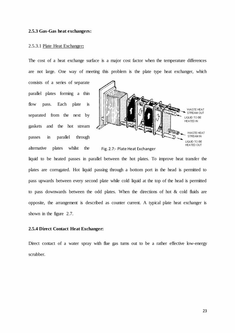
2.5.3.1 Plate Heat Exchanger:
The cost of a heat exchange surface is a major cost factor when the temperature differences
are not large. One way of meeting this problem is the plate type heat exchanger, which
consists of a series of separate
parallel plates forming a thin
flow pass. Each plate is
separated from the next by
gaskets and the hot stream
passes in parallel through
alternative plates whilst the
liquid to be heated passes in parallel between the hot plates. To improve heat transfer the
plates are corrugated. Hot liquid passing through a bottom port in the head is permitted to
pass upwards between every second plate while cold liquid at the top of the head is permitted
to pass downwards between the odd plates. When the directions of hot & cold fluids are
opposite, the arrangement is described as counter current. A typical plate heat exchanger is
shown in the figure 2.7.
2.5.4 Direct Contact Heat Exchanger:
Direct contact of a water spray with flue gas turns out to be a rather effective low-energy
scrubber.
Fig. 2.7:- Plate Heat Exchanger

24
2.6 POSSIBLE USES OF WASTE HEAT
There are various ways of utilizing waste heat depending on the quality. A few uses have
been shown in table 2.7.
Table 2.7:-Uses of Waste Heat
Sl. No. Possible Uses Temperature Range ( C)
1 Absorption Refrigeration 120-140 degrees steam
2 Adsorption Refrigeration -do-
3 DeHumidification Around 80-85 degrees hot water
4 Building Heating 80 - 130 degrees
5 Organic Rankine cycle
( power generation )
Around 65 degrees
6 Steam Rankine Cycle
( Power Generation )
Around 530 degrees

25
CHAPTER 3
PROBLEM STATEMENT
3.1 CASE STUDY
The present work is based on the stream data of a typical sponge iron production plant with
overall capacity of 200tpd. The following data was collected to carry out the work.
3.1.1 Feed Stream:
The feed mix fed into the rotary kiln is of specific size and composition which is presented in
table 3.1. The sources and temperatures of each component have been mentioned too.
Table 3.1: Feed Stream Properties
Raw Material Source Particle Size (mm) Feed Temp(C) Flow Rate(tph)
Iron Ore Barbil 5-18 30 6
Coal M.C.l <18 30 3.3
Dolomite Chattisgarh 2-6 30 0.2
3.1.2 Dust Settling Chamber:
The Flue gas enters the dust settling chamber where the dust gets separated. The properties of
the gas at inlet and outlet of Dust Settling Chamber are shown in table 3.2.
Table3.2: Gaseous Stream at Dust Settling Chamber
Inlet Temp(C) Outlet Temp(C) Flow Rate(tph) Pressure(mb)
900-950 900-950 25.06 5
26
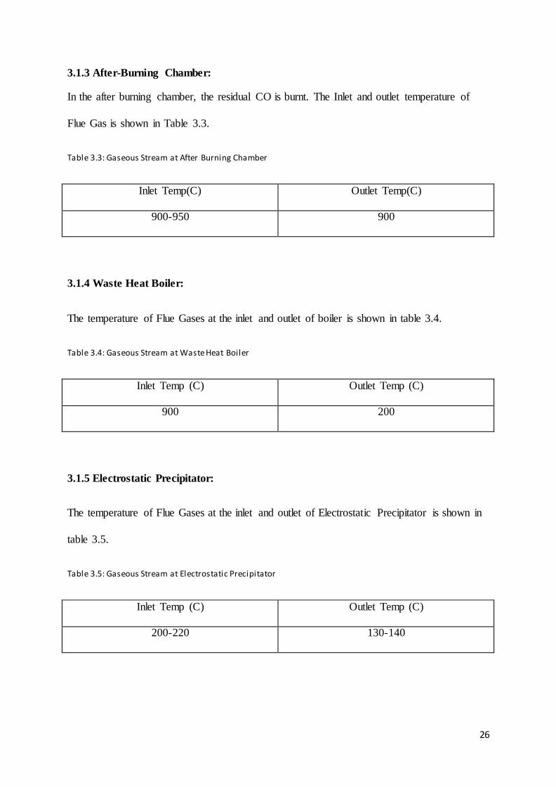
3.1.3 After-Burning Chamber:
In the after burning chamber, the residual CO is burnt. The Inlet and outlet temperature of
Flue Gas is shown in Table 3.3.
Table 3.3: Gaseous Stream at After Burning Chamber
Inlet Temp(C) Outlet Temp(C)
900-950 900
3.1.4 Waste Heat Boiler:
The temperature of Flue Gases at the inlet and outlet of boiler is shown in table 3.4.
Table 3.4: Gaseous Stream at Waste Heat Boiler
Inlet Temp (C) Outlet Temp (C)
900 200
3.1.5 Electrostatic Precipitator:
The temperature of Flue Gases at the inlet and outlet of Electrostatic Precipitator is shown in
table 3.5.
Table 3.5: Gaseous Stream at Electrostatic Precipitator
Inlet Temp (C) Outlet Temp (C)
200-220 130-140

27
3.2 FLOW SHEET
The flow sheet of the sponge iron production process with material and energy is shown in
Figure3.1.
Figure 3.1: Flow Sheet of Typical Sponge Iron Plant
28
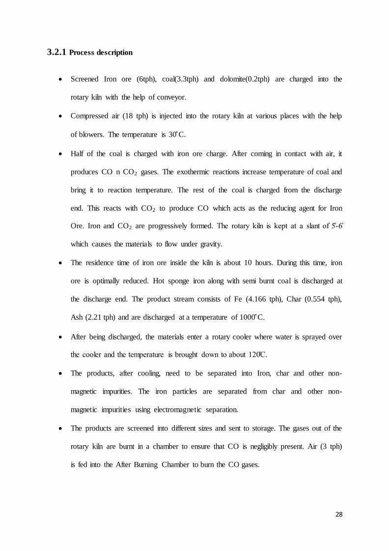
3.2.1 Process description
Screened Iron ore (6tph), coal(3.3tph) and dolomite(0.2tph) are charged into the
rotary kiln with the help of conveyor.
Compressed air (18 tph) is injected into the rotary kiln at various places with the help
of blowers. The temperature is 30 C.
Half of the coal is charged with iron ore charge. After coming in contact with air, it
produces CO n CO2 gases. The exothermic reactions increase temperature of coal and
bring it to reaction temperature. The rest of the coal is charged from the discharge
end. This reacts with CO2 to produce CO which acts as the reducing agent for Iron
Ore. Iron and CO2 are progressively formed. The rotary kiln is kept at a slant of -
which causes the materials to flow under gravity.
The residence time of iron ore inside the kiln is about 10 hours. During this time, iron
ore is optimally reduced. Hot sponge iron along with semi burnt coal is discharged at
the discharge end. The product stream consists of Fe (4.166 tph), Char (0.554 tph),
Ash (2.21 tph) and are discharged at a temperature of 1000 C.
After being discharged, the materials enter a rotary cooler where water is sprayed over
the cooler and the temperature is brought down to about 1 C.
The products, after cooling, need to be separated into Iron, char and other non-
magnetic impurities. The iron particles are separated from char and other non-
magnetic impurities using electromagnetic separation.
The products are screened into different sizes and sent to storage. The gases out of the
rotary kiln are burnt in a chamber to ensure that CO is negligibly present. Air (3 tph)
is fed into the After Burning Chamber to burn the CO gases.

29
The gases . tph , at a temperature of 1 C, enter the waste heat boiler and then
E P from where they are routed to the stack at a temperature of - C.
Dust is separated at ESP at around 1.56 tph.
3.3 AREAS OF INTEREST FOR HEAT INTEGRATION
3.3.1 Rotary Cooler:
Rotary cooler receives hot iron, char etc and cools them indirectly using water from around
1 C to about 1 C. This means a temperature drop of around - C. This heat can be
used elsewhere and can cause considerable savings of heat energy. At present, the hot water
is simply thrown away which is a big loss.
3.3.2 Stack Gases:
The stack gases consist of mainly CO2 and air at temperature around C. If the boiler
efficiency cannot be improved more, then we can use the stack gas to recover more heat and
then release it to the atmosphere.

30
CHAPTER 4
ENERGY CONSERVATION MEASURES
4.1 POTENTIAL AREAS FOR HEAT INTEGRATION
The two areas where energy is to be conserved are Stack region and Rotary cooler region.
The stack gases are released to the atmosphere at a temperature of 230 C. Usable heat can be
extracted and then these gases can be released to the atmosphere at around a temperature of
140-150 C. The rotary cooler employs cooling water at a rate of around 180tph. Water
extracts the heat of Products and their temperature is brought down from 1000 C to 100 C.
The idea proposed in this project, is to use the hot stack gases to preheat the combustion air
fed to the rotary kiln. Currently, combustion air is fed into the rotary kiln at 30 C. The air
temperature has to be increased to the combustion temperature at the expense of extra coal. If
the combustion air is preheated before being fed into the kiln an equivalent amount of coal
can be saved.
After preheating the combustion air, the stack gases get cooled. These gases can now be used
in the rotary cooler region to cool the Products in a direct contact cooler. This will save a lot
of water. In this process, the stack gases get heated up and reach a temperature enough to be
released to atmosphere. Thus, the proposed system will consist of:
1) A duct to carry the flue gases from Electrostatic Precipitator to Rotary Kiln.
2) An Air-Preheater (Plate type Heat exchanger)
3) A Flue Gas Cooler (Fin-type Exchanger) to reduce the temperature of flue gases.
4) Gas-Solid Heat Exchanger to cool the products using cold flue gas instead of water.
5) A return duct to carry the flue gases back to chimney

31
4.2 DESIGN PROCEDURE
4.2.1 Duct
The purpose of the duct is to carry the flue gas from ESP to Rotary Kiln & Cooler. In general,
the Mild Steel can be taken as the material of construction of the duct. A suitable diameter is
to be selected. As the diameter of the duct increases, the fixed costs (material Cost) increase
but the Pressure drop along the duct goes on decreasing and vice versa. This calls a trial &
error method. Following procedure was followed to calculate duct diameter.
1) A range of diameters was selected (0.1-2 m).
2) Corresponding velocities and Nre (Reynolds Number), Npr (Prandtl Number) were
calculated for each diameter. Details are shown in Table A.1.
3) Film Coefficients for Flue Gas (hi) & Air (ho) were calculated & Overall coefficient
Ui was calculated for each diameter.
4) The weighted-average Ui was calculated. Details are shown in Table A.2.
5) A range of temperature drops was selected (1-10 C). Air temperature was assumed to
constant at 45 C.
6) Log-Mean Temperature Difference, Heat Lost, Area and Diameter were calculated for
each temperature drop, using the weight-average Ui. Details are shown in Table A.3.
7) For each of the Diameters obtained in step 6, the pressure drop, number of FD Fans,
Duct cost, Electricity costs were calculated and the Total Expense was plotted against
Diameter. Details are shown in Table A.4.
8) The diameter corresponding to minimum cost was selected. Details are shown in
Fig.A.1.
32
9) The actual heat transfer coefficient was calculated for this diameter and then the
corresponding heat loss and outlet temperature calculated. Details are shown in Table
A.5.
10) Glass insulation was selected and calculated thickness was applied to restrict the
temperature drop in the duct to 1 C. Details are shown in Table A.6.
4.2.2 Air-Preheater
The purpose of air-preheater is to preheat the combustion air. Air enters the exchanger at
temperature of 30 C. Usually Gasketed-Plate Heat Exchangers are used for air Preheaters.
HTRI Xchanger Suite 5.0 was used to design the heat exchanger. Following procedure was
followed.
1) For a range of temperature drops, the heat duty was calculated for each drop.
2) Keeping a gradient of around 50 C at the hot end, corresponding Heat duty was
calculated. Details are shown in Table B.1.
3) Using HTRI Xchanger Suite 5.0, the flow rates of Flue gas & air, the temperature
ranges and fouling factors were entered [15].
4) The Plate area, channels/pass, channel spacing and port diameter was adjusted to give
results with least percentage of overdesign.
5) The results returned by HTRI Xchanger Suite 5.0 viz. as no. of channels/pass, no. of
plates, pressure drop and area were registered. Details are shown in Fig. B.1.
4.2.3 Flue Gas-Water heat exchanger
The purpose of this heat exchanger is to cool the flue-gas to a temperature of 60 C, so that it
can be used in the rotary cooler to cool the hot products. Since the heat transfer coefficient on
the gas side is usually less, a Fin-type Shell& tube Heat Exchanger was designed. Waster is

33
used as the cooling medium. HTRI Xchanger Suite 5.0 was used to design the heat
exchanger. Following procedure was followed.
1) The allowable outlet temperature for water was selected as 90 C and the flow rate was
calculated. Details are shown in Table C.1.
2) Using HTRI Xchanger Suite 5.0, the flow rates of Flue gas & water, the temperature
ranges were entered.
3) The pipe diameter, length, pitch, shell diameter, fin specifications were adjusted to
give the least percentage of overdesign.
4) The results returned by HTRI Xchanger Suite 5.0 viz. as no. of tubes, shell diameter,
tube diameter, pitch, baffle-spacing, pressure drop and area were registered [12].
Details are shown in Fig.C.1.
4.2.4 Gas-solid heat exchanger
The rotary cooler cools the products using flue gas as the cooling medium. A suitable
diameter has to be chosen for adequate heat transfer. Following Procedure was calculated
for designing the gas-solid heat exchanger.
1) Heat duty was calculated from energy balances.
2) Design is based upon the amount of heat lost to the surroundings. The fraction of heat
lost to surroundings is assumed (based on earlier work). Details are shown in Table
D.1.
3) The material (product) conductivity was calculated from material properties [9].
Details are shown in Table D.2.
4) The wall equivalent conductivity was calculated using wall material conductivity &
insulation conductivity. Details are shown in Table D.3.

34
5) For a range of diameters (1.5-4.5m), Ui values were calculated & an average value of
Ui was selected. Details are shown in Table D.4.
6) Using the values of LMTD, Heat Load & Ui, area of cooler was calculated.
7) Diameter was calculated using area. Insulation thickness was kept same as current
standards. Details are shown in Table D.5.
8) Pressure drop in the exchanger was calculated. Details are shown in Table D.6.
4.2.5 Return Duct
The return duct will carry the flue gases from Gas-Solid heat exchanger to the chimney. The
same principles apply to this duct as the first duct. So the diameter of this duct is kept same as
the first duct.
4.2.6 Cost Estimation
This consists of capital costs and operating costs.
4.2.6.1 Capital Costs
(
) [11], [16],[17].
4.2.6.2 Operating Costs
( )
4.2.6.3 Annual Savings
( ) ( )

35

36
CHAPTER 5
RESULTS & DISCUSSION
5.1 DESIGNED EQUIPMENT
The system designed in this project work is shown in the modified Flow sheet Figure 5.1
Fig 5.1:- Modified Flow Sheet of SL/RN Process
5.1.1 Duct
The material was selected as mild steel because it is highly heat and corrosion resistant. The
distance of stack from rotary kiln is 35 m, hence the length. Wall thickness is usually taken as
8mm, in general [10]. The duct diameter was selected in such a way that only one FD Fan is

37
required to carry the gas through the duct. Any further reduction in diameter will cause a
higher pressure drop. This will require more than one FD Fans which increase the Capital
costs considerably. The design parameters for the duct is shown in Table 5.1
Table 5.1:- Duct Specification
Parameter Value/Type Unit
Material Mild Steel -
Diameter 0.309 m
Length 35 m
Wall thickness 8 mm
Pressure drop 51.5 KPa
The annual fixed costs (depreciation of duct and compressor) were plotted against Diameter
and the diameter corresponding to the least cost was chosen. The graph is shown in Figure
5.2.
Figure 5.2:- Annual Cost~ Diameter Curve
0
2000000
4000000
6000000
8000000
10000000
12000000
0.000 0.200 0.400 0.600 0.800 1.000 1.200
Annual Fixed Cost
AA+B+C
Diameter,m
Rs./Yr
38
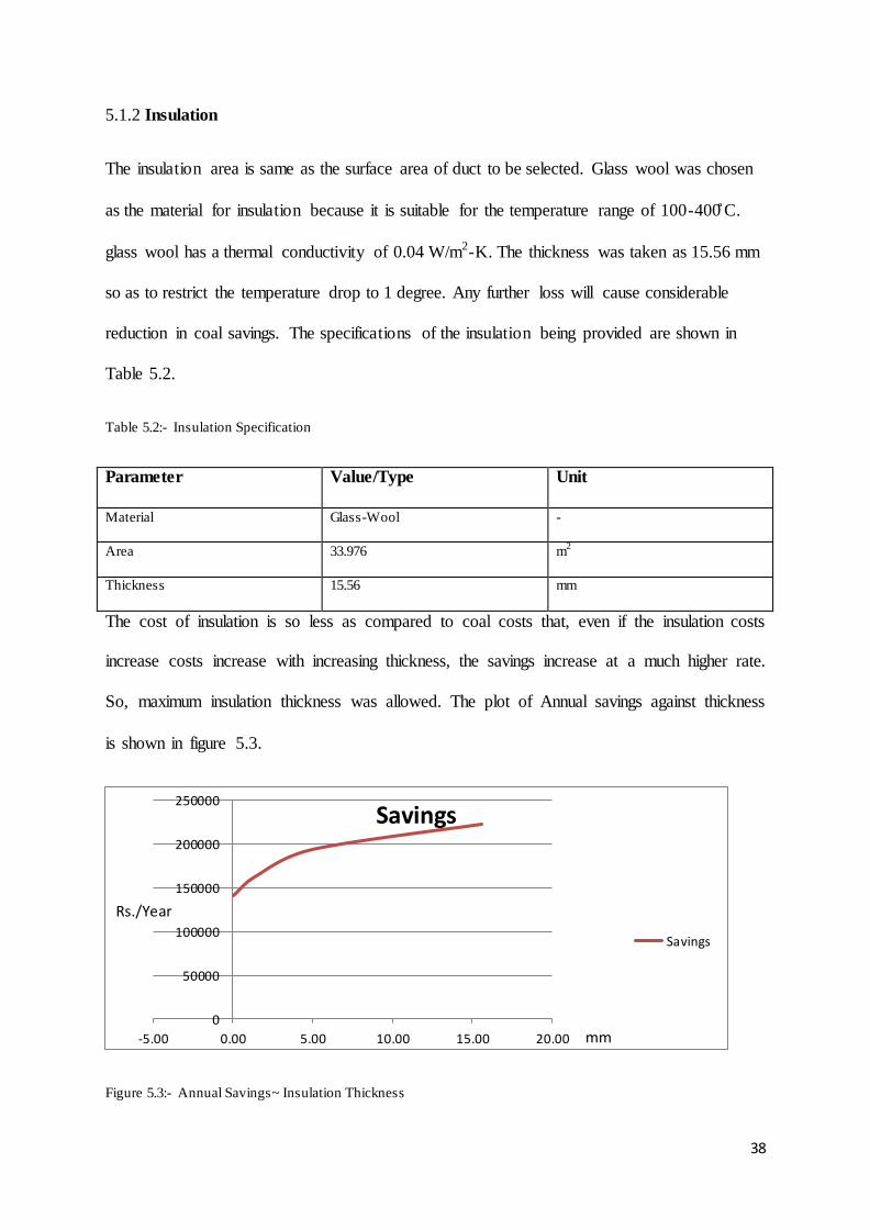
5.1.2 Insulation
The insulation area is same as the surface area of duct to be selected. Glass wool was chosen
as the material for insulation because it is suitable for the temperature range of 100-400 C.
glass wool has a thermal conductivity of 0.04 W/m2-K. The thickness was taken as 15.56 mm
so as to restrict the temperature drop to 1 degree. Any further loss will cause considerable
reduction in coal savings. The specifications of the insulation being provided are shown in
Table 5.2.
Table 5.2:- Insulation Specification
Parameter Value/Type Unit
Material Glass-Wool -
Area 33.976 m2
Thickness 15.56 mm
The cost of insulation is so less as compared to coal costs that, even if the insulation costs
increase costs increase with increasing thickness, the savings increase at a much higher rate.
So, maximum insulation thickness was allowed. The plot of Annual savings against thickness
is shown in figure 5.3.
Figure 5.3:- Annual Savings~ Insulation Thickness
0
50000
100000
150000
200000
250000
-5.00 0.00 5.00 10.00 15.00 20.00
Savings
Savings
mm
Rs./Year

39
5.1.3 Air-Preheater
Air preheaters are usually plate type heat exchangers because they give a higher value of heat
transfer coefficient. Therefore, Gasketed Plate type exchanger was designed. The area was
calculated from heat duty. The no. of channels had to be adjusted to give less pressure drop
and simultaneously les overdesign values. Channel spacing and port diameters were adjusted
to have lower pressure drops. Chevron angle was adjusted to give higher coefficient. Finally,
the area of plate heat exchanger was found to be 61.5 sq.m. by trial and error method using
HTRI Xchanger Suite 5.0. The specifications of the Air Preheater have been shown in table
5.3.
Table 5.3:- Air Preheater Specifications
Parameter Value Unit
Area 61.5 m2
Heat Duty 626 KW
Coal Savings 618350 Kg/year
Channels per pass 21 -
No. of Plates 43 -
Channel spacing 10 mm
Chevron Angle 30 degrees
Port Diameter 130 mm
Flue Gas Pressure Drop 33 Kpa

40
5.1.4 Flue-Gas Cooler
The flue gas temperature at the outlet of Air Preheater is 165 C. The temperature has to be
brought down to 60 C. For this, a fin type heat exchanger was designed. Water at 30 C was
used as the cooling medium. The water outlet temperature was limited to 90 degrees to avoid
vaporisation which leads to less coefficient as well as cavitation in the pump. The exchanger
was used as fin type to have a higher heat transfer coefficient on shell side. The HTRI
Xchanger suite 5.0 was used to design the exchanger with minimum overdesign. The
adjustable parameters are Fin specifications, tube OD, pitch, Shell OD etc. Pressure drop was
taken care of by adjusting pitch and no. of fins. Finally the area was calculated to be 340
sq.m. The specifications of the Flue Gas Cooler are shown in table 5.4.
Table 5.4:- Flue Gas Cooler Specification
Parameter Value Unit
Type 1-1 Pass
Area 340 m2
No. of Tubes 255 -
Shell ID 712 mm
Tube OD 25.4 mm
Tube Wall Thickness 0.711 mm
Tube Length 4.877 m
Pitch 35 mm
No. of Fins 20 -
Fin thickness 0.8 mm
Fin height 5 mm
Flue-Gas Pressure Drop 3.18 KPa
Water Pressure Drop 4.836 Kpa

41
5.1.5 Solid-Gas Heat Exchanger
In the Solid-Gas Heat Exchanger, the insulation thickness and material have been kept same
as existing insulation. Material selected was mild steel. This was chosen because the existing
rotary coolers in typical sponge iron plants are made of mild steel. Wall thickness, in general,
was taken to be 8mm. Heat duty was calculated to be 996 KW. The fraction of heat lost was
calculated to be 160 KW (16%). The conductivity of material was calculated to be 0.953 KW
using parallel thermal resistance method. Average coefficient was taken to be 3.18 W/sq.m K
by taking average of a range of values. The area required was calculated to be around 150
sq.m. The L/D ratio was kept, in general, equal to 40/3. This way the diameter was calculated
to be 1.7 m and length to be 28m. Refractory material and thickness was kept same as the
existing coolers. Flue gas outlet temperature was calculated using energy balance. The
specifications of the solid-gas heat exchanger are shown in table 5.5.
Table 5.5:- Solid-Gas Heat Exchanger Specifications
Parameter Value/Type Unit
Material of wall Mild Steel -
Length 28 m
Inner Diameter 1.7 m
Wall Thickness 8 mm
Refractory Material Whytheat-C -
Refractory Thickness 192 mm
Pressure Drop 0.03 KPa
Flue Gas Outlet Temperature 140 C

42
5.1.6 Return Duct
The return duct was designed on the same principles as the first insulated duct. The
specifications of the return duct are given in table 5.6.
Table 5.6:- Return Duct Specifications
Parameter Value/Type Unit
Material Mild Steel -
Diameter 0.309 m
Length 35 m
Wall thickness 8 mm
Pressure drop 51.5 KPa
5.2 COST ESTIMATION
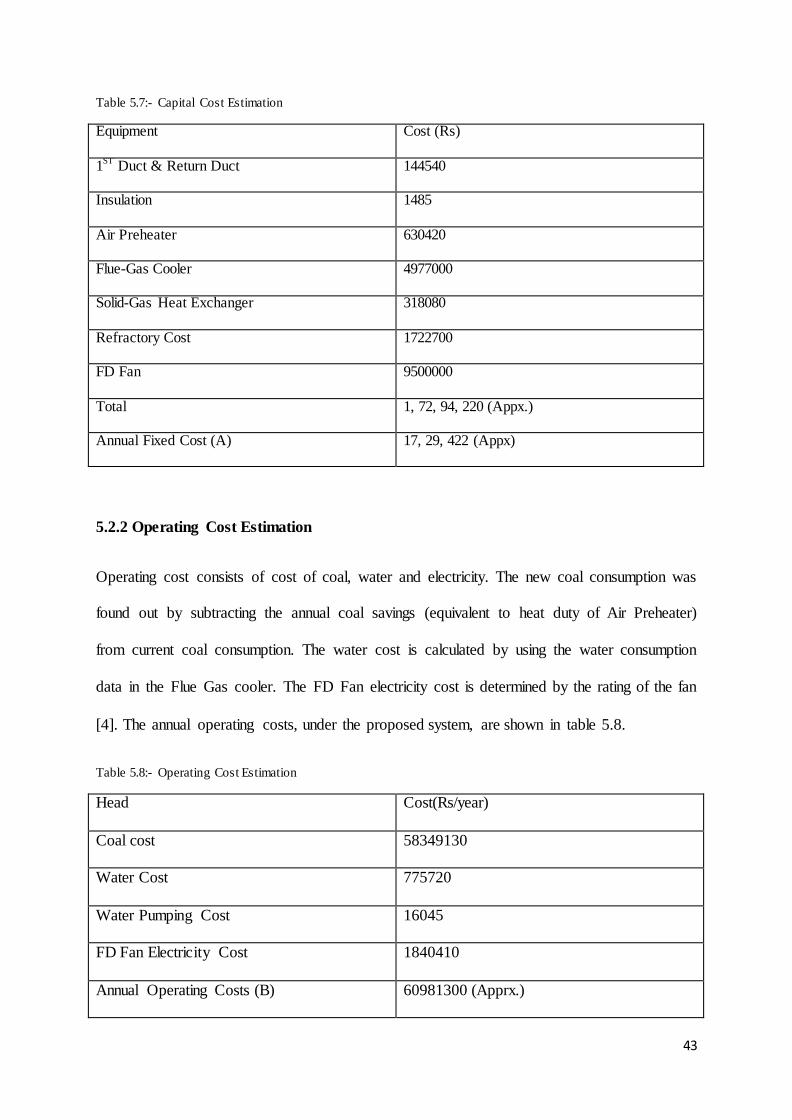
5.2.1 Capital Cost Estimation
Capital cost was found by adding the cost of the proposed equipment. The duct costs were
calculated by calculating the weight of material required and multiplying with price per unit
weight. The insulation volume, density and weight were calculated and the insulation price
was determined by multiplying with price per unit weight. Air-Preheater and Flue Gas cooler
costs were determined by comparing with plots of Area against Cost [10], [11]. The Solid-
Gas heat exchanger cost was found by adding the material cost and refractory cost. The FD
Fan cost was found by referring to manufacturer‟s manual [ ]. The total capital cost is shown
in table 5.7.
43
Table 5.7:- Capital Cost Estimation
Equipment Cost (Rs)
1ST
Duct & Return Duct 144540
Insulation 1485
Air Preheater 630420
Flue-Gas Cooler 4977000
Solid-Gas Heat Exchanger 318080
Refractory Cost 1722700
FD Fan 9500000
Total 1, 72, 94, 220 (Appx.)
Annual Fixed Cost (A) 17, 29, 422 (Appx)
5.2.2 Operating Cost Estimation
Operating cost consists of cost of coal, water and electricity. The new coal consumption was
found out by subtracting the annual coal savings (equivalent to heat duty of Air Preheater)
from current coal consumption. The water cost is calculated by using the water consumption
data in the Flue Gas cooler. The FD Fan electricity cost is determined by the rating of the fan
[4]. The annual operating costs, under the proposed system, are shown in table 5.8.
Table 5.8:- Operating Cost Estimation
Head Cost(Rs/year)
Coal cost 58349130
Water Cost 775720
Water Pumping Cost 16045
FD Fan Electricity Cost 1840410
Annual Operating Costs (B) 60981300 (Apprx.)

44
5.2.3 Total Annual Cost
Total Annual cost = A+B = 1729422+60981300= Rs.62710720 (C)
5.2.4 Existing Capital Cost
For the existing system, the cost of rotary cooler and refractory cost is added, and the capital
cost is shown in table 5.9.
Table 5.9:- Existing Capital Cost Estimation
Equipment Cost(Rs.)
Rotary Cooler 400940
Refractory Cost 2171470
Total Capital Cost 2572406
Annual Fixed Cost A” 257240
5.2.5 Existing Operating Cost
The existing operating cost is based on the current consumption of coal, water and cost of
pumping water. The pump rating was taken from practical plant data and the operating cost
was calculated. Table 5.10 shows the existing Operating costs.
Table 5.10:-Existing Operating Cost
Head Cost(Rs/year)
Coal cost 59895000
Water Cost 9198420
Water Pumping Cost 1415700
Annual Operating Costs B” 70509120 (Apprx.)

45
5.2.6 Existing Total Annual Cost
Total Existing Annual cost = A”+B” = 257240 + 70509120= 70766360 (C”)
5.2.7 Annual Savings
Annual savings = B-B” = Rs.95,27,820/-
Total Capital Cost= Rs. 1,72,94,217/-
Payback Period= 1.81 years
Amount of coal savings = 618350 kg
Amount of water savings = 1,183,903 tons

46
CHAPTER 6
CONCLUSIONS
In the present work waste heat recovery system is designed to integrate the heat of waste gas
in the sponge iron production process. The salient features of the study are as follows:
1) The instalment of the above system requires a capital cost of approximately Rs.173 lakh.
2) The major components contributing to the annual savings are Coal and water. The annual
Coal savings was calculated to be 618350 kg which amounts to Rs. 15.5 lakh. The annual
water savings was calculated to be 11.8 million tons which amounts to Rs. 83 lakh. Total
annual savings was calculated to be Rs.95.3 lakh.
3) With these annual savings, the Payback Period was calculated to be 1.81 years.
The advantage of this system is that it utilises the waste heat trapped in the stack gases and
simultaneously reduces the water consumption by a considerable amount. Unlike older waste
heat recovery systems (waste heat boilers etc), it does not require much higher temperatures.
The system solves the purpose of extracting heat from low quality sources. After the flue
gases pass through the Gas-Solid Heat Exchanger, they attain a temperature of around 140 C
which is sufficient to lower their density and raise them upwards.
Therefore, it is concluded that this system can be applied to sponge iron plants.
47
BIBLIOGRAPHY
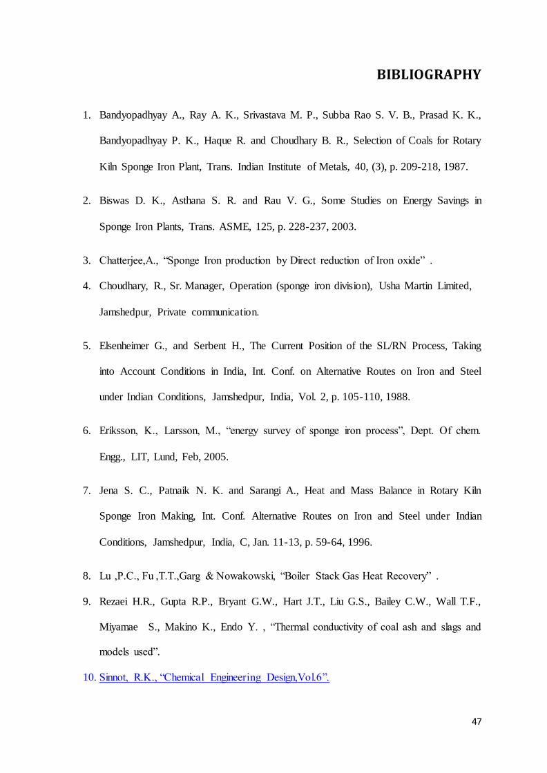
1. Bandyopadhyay A., Ray A. K., Srivastava M. P., Subba Rao S. V. B., Prasad K. K.,
Bandyopadhyay P. K., Haque R. and Choudhary B. R., Selection of Coals for Rotary
Kiln Sponge Iron Plant, Trans. Indian Institute of Metals, 40, (3), p. 209-218, 1987.
2. Biswas D. K., Asthana S. R. and Rau V. G., Some Studies on Energy Savings in
Sponge Iron Plants, Trans. ASME, 125, p. 228-237, 2003.
3. Chatterjee,A., “ ponge Iron production by Direct reduction of Iron oxide” .
4. Choudhary, R., Sr. Manager, Operation (sponge iron division), Usha Martin Limited,
Jamshedpur, Private communication.
5. Elsenheimer G., and Serbent H., The Current Position of the SL/RN Process, Taking
into Account Conditions in India, Int. Conf. on Alternative Routes on Iron and Steel
under Indian Conditions, Jamshedpur, India, Vol. 2, p. 105-110, 1988.
6. Eriksson, K., Larsson, M., “energy survey of sponge iron process”, Dept. Of chem.
Engg., LIT, Lund, Feb, 2005.
7. Jena S. C., Patnaik N. K. and Sarangi A., Heat and Mass Balance in Rotary Kiln
Sponge Iron Making, Int. Conf. Alternative Routes on Iron and Steel under Indian
Conditions, Jamshedpur, India, C, Jan. 11-13, p. 59-64, 1996.
8. Lu ,P.C., Fu ,T.T.,Garg & Nowakowski, “Boiler tack Gas Heat Recovery” .
9. Rezaei H.R., Gupta R.P., Bryant G.W., Hart J.T., Liu G.S., Bailey C.W., Wall T.F.,
Miyamae S., Makino K., Endo Y. , “Thermal conductivity of coal ash and slags and
models used”.
10. innot, R.K., “Chemical Engineering Design,Vol. ”.

48
11. www.cyberjournalist.org.in/manisana/aicpi.php
12. www.engineeringtoolbox.com/pumps-power-d_505.html
13. www.en.wikipedia.org/wiki/Direct_reduced_iron
14. www.hardtech.es/hgg_tt_hrt.0.html
15. www.hcheattransfer.com/fouling_factors2.html
16. www.kundanrefractories.tradeindia.com/Exporters_Suppliers/Exporter15209.227263/
Whytheat-A-K-C.html
17. www.meps.co.uk/indian%20steel%20prices.htm
18. www.scribd.com/doc/23452858/Chapter-Waste-Heat-Recovery
19. www.siemens.com/energy
20. www.tatasponge.com/products/technology.asp
49
APPENDIX A
DESIGN OF DUCT
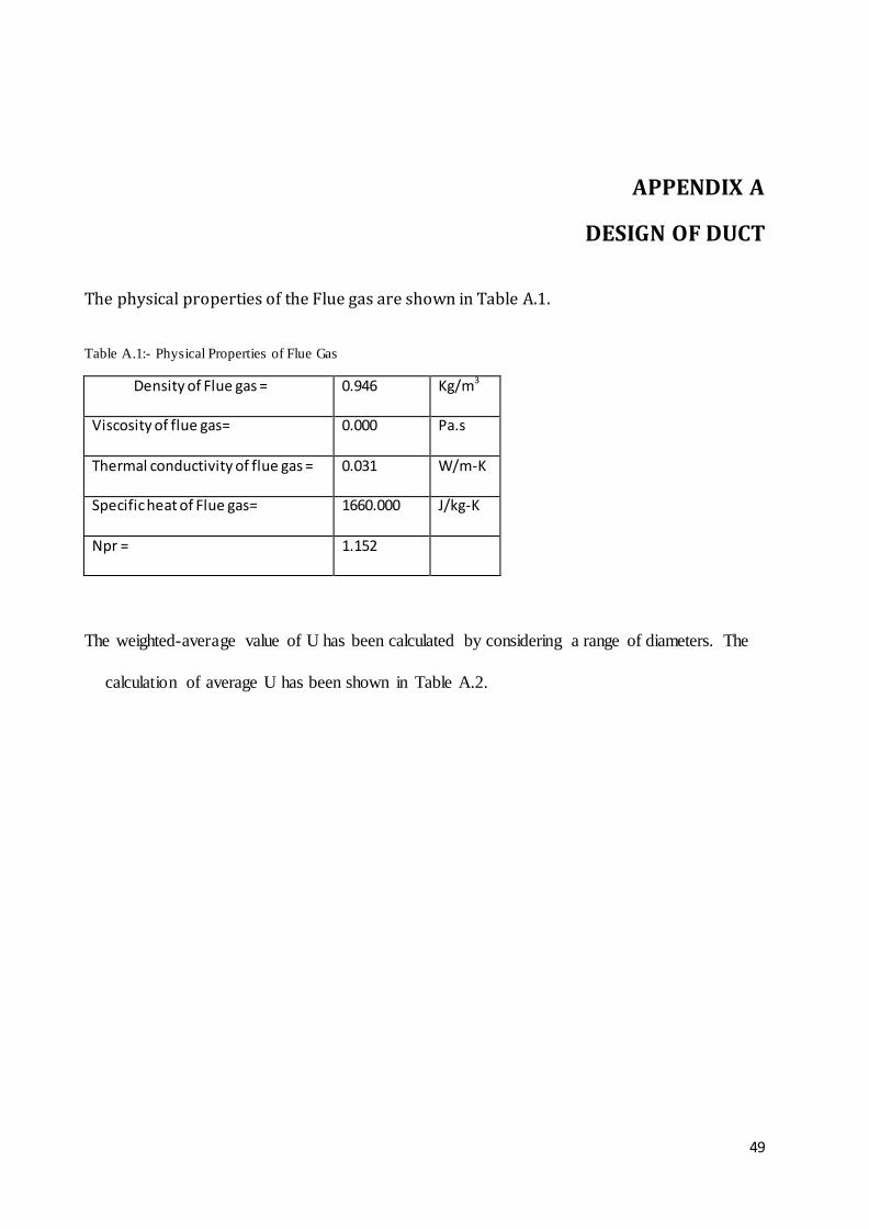
The physical properties of the Flue gas are shown in Table A.1.
Table A.1:- Physical Properties of Flue Gas
Density of Flue gas = 0.946 Kg/m3
Viscosity of flue gas= 0.000 Pa.s
Thermal conductivity of flue gas = 0.031 W/m-K
Specific heat of Flue gas= 1660.000 J/kg-K
Npr = 1.152
The weighted-average value of U has been calculated by considering a range of diameters. The
calculation of average U has been shown in Table A.2.

50
Table A.2:- Calculation of average U
Diameter CS Area Viscocity FG Flow Nre Npr Nu hi ho U U*D
(m) (sq.m) (Pa.s) (kg/h) (G*D/μ) (Cp*μ)/k
(W/ m2K)
(W/
m2K)
0.1 0.008 2.180E-05 25770 4180859 1.152 4778 1500.217 10 9.916 0.992
0.2 0.031 2.180E-05 25770 2090430 1.152 2744 430.824 10 9.756 1.951
0.3 0.071 2.180E-05 25770 1393620 1.152 1984 207.652 10 9.524 2.857
0.4 0.126 2.180E-05 25770 1045215 1.152 1576 123.722 10 9.237 3.695
0.5 0.196 2.180E-05 25770 836172 1.152 1318 82.796 10 8.908 4.454
0.6 0.283 2.180E-05 25770 696810 1.152 1139 59.632 10 8.551 5.131
0.7 0.385 2.180E-05 25770 597266 1.152 1007 45.183 10 8.176 5.723
0.8 0.503 2.180E-05 25770 522607 1.152 905 35.530 10 7.793 6.234
0.9 0.636 2.180E-05 25770 464540 1.152 824 28.742 10 7.409 6.668
1.0 0.785 2.180E-05 25770 418086 1.152 757 23.777 10 7.031 7.031
1.1 0.950 2.180E-05 25770 380078 1.152 702 20.028 10 6.662 7.328
1.2 1.131 2.180E-05 25770 348405 1.152 654 17.125 10 6.306 7.568
1.3 1.327 2.180E-05 25770 321605 1.152 614 14.827 10 5.966 7.756
1.4 1.539 2.180E-05 25770 298633 1.152 579 12.975 10 5.642 7.899
1.5 1.767 2.180E-05 25770 278724 1.152 547 11.460 10 5.335 8.003
1.6 2.011 2.180E-05 25770 261304 1.152 520 10.203 10 5.046 8.073
1.7 2.270 2.180E-05 25770 245933 1.152 495 9.148 10 4.774 8.115
1.8 2.545 2.180E-05 25770 232270 1.152 473 8.254 10 4.518 8.133
1.9 2.835 2.180E-05 25770 220045 1.152 453 7.489 10 4.279 8.130
2.0 3.142 2.180E-05 25770 209043 1.152 435 6.828 10 4.055 8.109
20.0
114.353
Average
U= 5.718
51
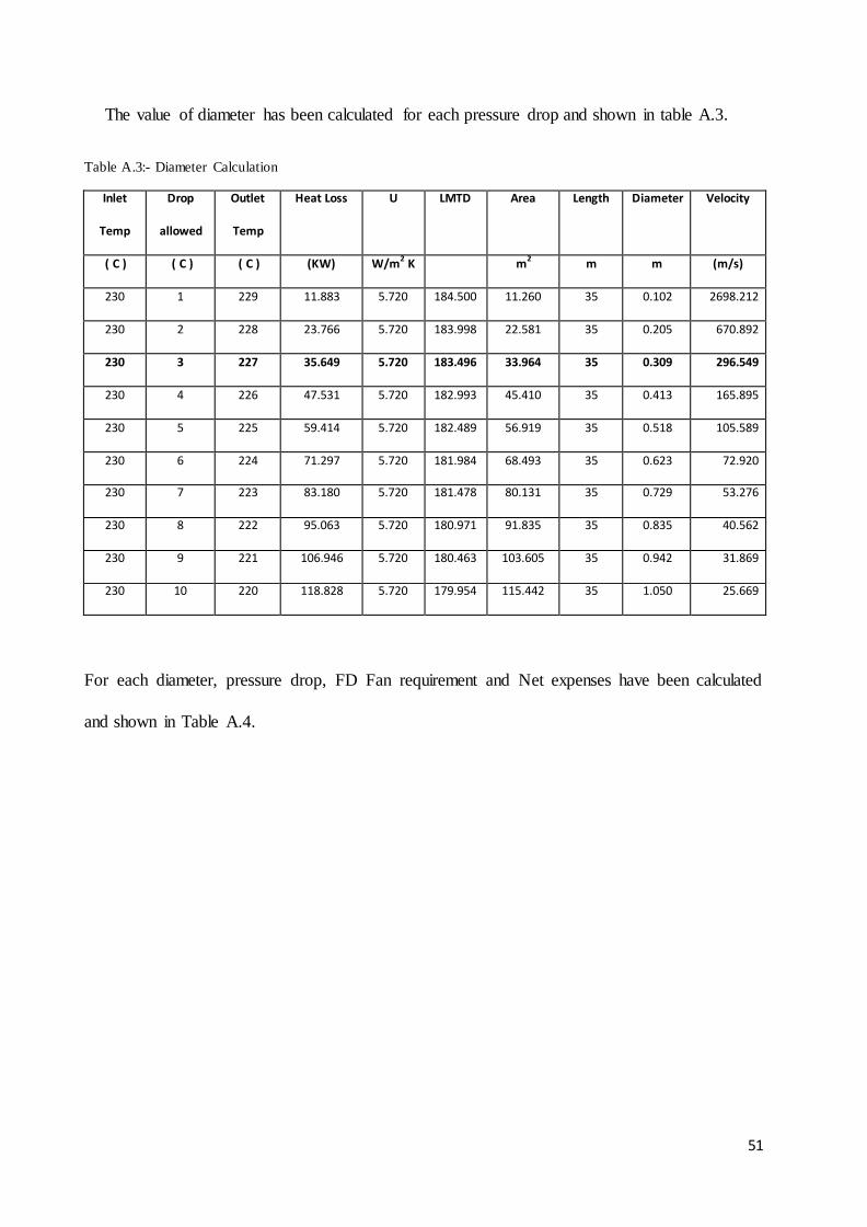
The value of diameter has been calculated for each pressure drop and shown in table A.3.
Table A.3:- Diameter Calculation
Inlet
Temp
Drop
allowed
Outlet
Temp
Heat Loss U LMTD Area Length Diameter Velocity
( C ) ( C ) ( C ) (KW) W/m2 K m2 m m (m/s)
230 1 229 11.883 5.720 184.500 11.260 35 0.102 2698.212
230 2 228 23.766 5.720 183.998 22.581 35 0.205 670.892
230 3 227 35.649 5.720 183.496 33.964 35 0.309 296.549
230 4 226 47.531 5.720 182.993 45.410 35 0.413 165.895
230 5 225 59.414 5.720 182.489 56.919 35 0.518 105.589
230 6 224 71.297 5.720 181.984 68.493 35 0.623 72.920
230 7 223 83.180 5.720 181.478 80.131 35 0.729 53.276
230 8 222 95.063 5.720 180.971 91.835 35 0.835 40.562
230 9 221 106.946 5.720 180.463 103.605 35 0.942 31.869
230 10 220 118.828 5.720 179.954 115.442 35 1.050 25.669
For each diameter, pressure drop, FD Fan requirement and Net expenses have been calculated
and shown in Table A.4.

52
Table A.4:- Net Expenses
Diameter ΔP
(KPa)
FD
Fans
Reqd
Electricity(AA) Duct
Cost
Annual
Dep(B)
Maintainance
(BB)
Fan Costs Annual
dep(C )
NET
EXPENSES3
m Rs/year(39
kw)
Rs Rs/Year Rs/year Rs Rs/year AA+B+BB+C
0.102 10313.296 104 23950 2395 1197
0.205 365.411 4 7361640 48030 4803 2402 38000000 3800000 11168845
0.309 51.504 1 1840410 72243 7224 3612 9500000 950000 2801246
0.413 12.777 1 1840410 96589 9659 4829 9500000 950000 2804898
0.518 4.320 1 1840410 121069 12107 6053 9500000 950000 2808570
0.623 1.777 1 1840410 145686 14569 7284 9500000 950000 2812263
0.729 0.837 1 1840410 170441 17044 8522 9500000 950000 2815976
0.835 0.435 1 1840410 195336 19534 9767 9500000 950000 2819710
0.942 0.244 1 1840410 220371 22037 11019 9500000 950000 2823466
The net expenses were plotted against diameter and the graph is shown in fig A.1.
Figure A.1:- Net Expenses ~ Diameter Plot
The lowest diameter was selected and actual U and outlet temperature were calculated. The
calculations have been shown in table A.5.
0
2000000
4000000
6000000
8000000
10000000
12000000
0.000 0.200 0.400 0.600 0.800 1.000 1.200
Net Expenses
AA+B+C

53
Table A.5:- Actual U & Outlet Temperature
Diameter = 0.309 m
Nre = 1353519.8
viscosity = 0.0000218 Pa.s
Specific Heat capacity = 1660 j/kg-K
Thermal conductivity = 0.03 W/m-K
Npr= 1.15
Nu = 1938.40
hi= 26.01 W/sq.m-K
Air coefficient, ho = 10 W/sq.m-K
Pipe wall thickness, Xw= 0.008 m
Pipe material = mild steel
Kms= 45 W/sq-m-K
Insulation conductivity = 0.04 W/m-K
U= 7.21
Theoritical Heat Lost = 35.6485 KW
Assumed U= 5.72
Actual U= 7.21
Actual Heat Lost = 44.96 KW
Inlet Temp= 230 C
Temp Drop 3.78 C
Outlet Temp = 226.22 C

54
The insulation thickness was calculated for different temperature drops and the values are
shown in table A.6.
Table A.6:- Insulation Thickness ~ Temp Drop
Inlet
Temp
Drop
allowed
Outlet
Temp
LMTD Area(inside) heat lost New Ui Old Ui Insulation
(x)
Insulation
( C ) ( C ) ( C ) ( C ) (sq.m) (KW) (W/sq.m-
K)
(W/sq.m-K) m mm
230 3.78 226.22 183.103 33.976 44.917 7.220 7.220 0.0000 0.00
230 3 227 183.496 33.976 35.649 5.718 7.220 0.0015 1.46
230 2 228 183.998 33.976 23.766 3.802 7.220 0.0050 4.98
230 1 229 184.500 33.976 11.883 1.896 7.220 0.0156 15.56
For each insulation thickness, cost and net savings were calculated and the values are
presented in table A.7.
Table A.7:- Net Savings ~ Thickness
Insulation insulation
volume
weight Price Annual
Depr.
Total
annual
fixed cost
Heat
Savings
Annual
Savings
Coal Saved Cost
saved
Net
Savings
mm cu.m kg (rs) (rs) rs KW KJ Kg rs Rs
0.00 0.000 0.00 0 0 0 56.919 1487632109 56223.199 140558 140558
1.46 0.049 1.98 138 14 15 66.188 1729876500 65378.523 163446 163432
4.98 0.169 6.77 474 47 50 78.070 2040446232 77116.119 192790 192741
15.56 0.529 21.15 1480 148 155 89.953 2351015964 88853.714 222134 221979

55
APPENDIX B
DESIGN OF AIR PREHEATER
For different values of flue gas temperature drops, the outlet temperature of air was
calculated and the values are shown in Table B.1.
Table B.1:- Air Outlet Temperature
Inlet Flue T Outlet Flue T m*Cp (flue) Inlet Air T m*Cp (Air) Outlet Air T
229 65 11.88283333 30 5 419.7569333
229 70 11.88283333 30 5 407.8741
229 75 11.88283333 30 5 395.9912667
229 80 11.88283333 30 5 384.1084333
229 85 11.88283333 30 5 372.2256
229 90 11.88283333 30 5 360.3427667
229 95 11.88283333 30 5 348.4599333
229 100 11.88283333 30 5 336.5771
229 105 11.88283333 30 5 324.6942667
229 110 11.88283333 30 5 312.8114333
229 115 11.88283333 30 5 300.9286
229 120 11.88283333 30 5 289.0457667
229 125 11.88283333 30 5 277.1629333
229 130 11.88283333 30 5 265.2801
229 135 11.88283333 30 5 253.3972667
229 140 11.88283333 30 5 241.5144333
229 145 11.88283333 30 5 229.6316
229 150 11.88283333 30 5 217.7487667
229 155 11.88283333 30 5 205.8659333
229 160 11.88283333 30 5 193.9831

56
229 165 11.88283333 30 5 182.1002667
229 170 11.88283333 30 5 170.2174333
229 175 11.88283333 30 5 158.3346
The output of the HTRI Xchanger Suite 5.0 is presented in Figure B.1.

57
Figure B.1:- Software Output for Air Preheater

58
APPENDIX C
DESIGN OF FLUE-GAS COOLER
In the flue gas cooler, keeping the outlet temperature of water to be 90 degrees, the mass rate
of water was calculated. The calculation is shown in Table C.1.
Table C.1:- Mass & Energy Balance in Flue gas cooler
Mass rate of FG 7.158333 Kg/sec
Specific heat 1.66 KJ/kg
Temperature Drop 105 degrees
Water del T 60 degrees
specific heat 4.18 KJ/kg
Mass rate of Water= 4.97487
Using the above mass rate, the Flue gas cooler was designed using HTRI Xchanger Suite 5.0
and the output is shown in Figure C.1.

59
Fig.C.1:- Software Output for Flue Gas Cooler

60
APPENDIX D
DESIGN OF SOLID-GAS HEAT EXCHANGER
The heat duty of the Solid-Gas heat exchanger was calculated and the values are shown in
Table D.1.
Table D.1:- Heat & Mass balance in solid gas heat exchanger
Mass flow rate of Iron= 4.166 tph
Mass flow rate of Char= 0.554 tph
Mass flow rate of Ash= 2.21 tph
Total mass flow rate of solid products from kiln = Fe + Char + Ash = 6.93 tph
Inlet temperature of Solid materials = 1020 C
Outlet temperature of Solid materials= 110 C
specific heat capacity of Iron= 0.46 kJ/kg-K
specific heat capacity of char(charcoal)= 1 kJ/kg-K
specific heat capacity of ash(60%silica+40%alumina)= 0.664 kJ/kg-K
AVERAGE PECIFIC HEAT CAPACITY of solid materials= Σ mass-
fraction*specific heat)
0.568225 kJ/kg-K
Heat lost from solid materials=m.Cp.dT= 995.3883 kW
Assuming Fraction heat loss to surroundings = 0.16 (Based on earlier
reports)
So heat lost to the surroundings = 159.2621 kW
(This amount of heat is lost to the surroundings from the product

61
The thermal conductivity of the mixture of materials was calculated and the values are
presented in Table D.2.
Table D.2:- Calculation of Conductivity
The material consists of Iron, Char & Ash
Since the materials are mixed up, we can consider their thermal resistance to be parallel
in parallel resistances case, the lengths travelled are equal through all the resistances
The ratio of Areas can be cosidered equal to mass fractions
k1 = 60
k2=0.97
k3=0.55
putting these values, we get the value of material conductivity
k= 36.25 W/m.K
(
) (
) (
)
+
+
( )
( )
( )

62
The equivalent conductivity of the wall and refractory was calculated and the values are
presented in Table D.3.
Table D.3:- Equivalent wall conductivity
General wall thickness of ducts and coolers = 0.008 m
Thickness of refractory material = 0.192 m
R(equivalent) = R(Wall) + R(refractory)
Usually for coolers and driers, (outer radius / inner radius) < 1.4
so A(log-mean) = A(arithmetic mean)
putting the values in the relation , we get
General range of inner radius 1-1.5 m
Equivalent conductivity of wall, Keq = 0.953 W/m.K
(
) (
) (
)
(
( )) (
( )) (
( ))
( )

63
Using a range of diameter, an average coefficient U was calculated and the values are shown
in table D.4.
Table D.4:- Average Coefficient
k=thermal conductivity
w=wall (mild steel + refractory) Di Ui
m= (material inside cooler) 1.5 3.520612
ho = Heat transfer coefficient of air 2 3.326211
2.5 3.188254
The relation between coefficients is 3 3.079668
3.5 2.988712
4 2.909437
4.5 2.838485
putting all the values , we get the following relation
Using the value of average coefficient Ui, the area requirement was calculated. Keeping the
ratio of Length to Diameter as 40/3, the diameter and length were calculated and the values
are shown in table D.5.
(
) (
) (
) (
) (
) (
)
( )
( )

64
Table D.5:- Diameter and Length of Solid-Gas Heat Exchanger
Heat loss to surroundings, q= 159262.1 W
LMTD = 336 K
Heat transfer coefficient = Ui = 3.18 W/m2K
putting all values and solving the equations, we get
Area, Ai = 149.0548255 m2
Ai = π*Di*L = 149.0548255 m2
For Rotary drum coolers and dryers, L/Do = 40/3
Solving for this, we get
Di = 1.7 m
Do= 2.1 m
Length = L = 28 m
The pressure drop in the duct was calculated and the values are presented in table D.6.
Table D.6:- Pressure Drop in Gas-solid Exchanger
Equivalent Dia, Deq= 1.24 m
Flow Area= 1.70235 sq.m
Velocity= 13.0538 m/sec
Nre= 239182
f= 0.00386
delP= 29.7342 Pa