design of very low losses and high bandwidth rectangular microstrip patch antenna for satellite...
DESCRIPTION
The Microstrip Patch Antenna is now very famous due to its compact size, good gain and directivity bandwidth is mostly not very good in Microstrip patch antenna but in this paper bandwidth of the antenna is very high, Satellite Communication there is a need of very compact antenna ,This paper presents the designs of Compact C-band antenna for communication at 4GHz.antenna is Rectangular Microstrip Patch Antenna(RMPA),basic property of the antenna like simulated design, Return loss, directivity, Radiation Pattern and bandwidth are discussed. This work shows that whenever we increases cut width from 14mm to 16mm its bandwidth continuously increases and reached about up to 169 MHz and losses in 16mm cut width antenna reduces up to 100.972% that is very great achievement in Microstrip patch antenna for satellite communication.TRANSCRIPT

IJIRST –International Journal for Innovative Research in Science & Technology| Volume 2 | Issue 02 | July 2015 ISSN (online): 2349-6010
All rights reserved by www.ijirst.org 51
Design of Very Low Losses and High Bandwidth
Rectangular Microstrip Patch Antenna for
Satellite Communication
Vashali Kirar Ankita Gupta
Department of Electronics & Communication Engineering Department of Electronics & Communication Engineering
Vaishnavi Institute of Technology& Sciences Bhopal (M.P)-
India
Vaishnavi Institute of Technology& Sciences Bhopal (M.P)-
India
Hemant Kumar Gupta Dr. Vikas Maheshwari
Research Scholar Assistant Professor
Department of Electronics & Communication Engineering Department of Electronics & Communication Engineering
Amity University Madhyapradesh India Amity University Madhyapradesh India
Abstract
The Microstrip Patch Antenna is now very famous due to its compact size, good gain and directivity bandwidth is mostly not
very good in Microstrip patch antenna but in this paper bandwidth of the antenna is very high, Satellite Communication there is a
need of very compact antenna ,This paper presents the designs of Compact C-band antenna for communication at 4GHz.antenna
is Rectangular Microstrip Patch Antenna(RMPA),basic property of the antenna like simulated design, Return loss, directivity,
Radiation Pattern and bandwidth are discussed. This work shows that whenever we increases cut width from 14mm to 16mm its
bandwidth continuously increases and reached about up to 169 MHz and losses in 16mm cut width antenna reduces up to
100.972% that is very great achievement in Microstrip patch antenna for satellite communication.
Keywords: Rectangular Microstrip Patch Antenna (RMPA), Cut Width, Bandwidth, Return Loss, Directivity
_______________________________________________________________________________________________________
I. INTRODUCTION
Microstrip antennas for commercial systems require low-cost materials, simple and inexpensive fabrication techniques. Antennas
are the essential communication link for aircrafts and ships. Antennas for cellular phones and all types of wireless devices link us
to everyone and everything. With mankind’s activities expanding into space the need for antennas will grow to an unprecedented
degree. Antennas will provide the vital links to and from everything out there. [1]
A coaxial probe is connected to the rectangular patch which is located close to rectangular U-slot patch centre for good
excitation of the proposed antenna over a wide bandwidth. In this paper, a tetra band U-slot microstrip patch antenna is designed,
optimized and simulated. The antenna covers three frequency bands of 1.43-1.5 GHz,2.4-2.55 GHz, 3.8-3.98 GHz and 5.2-5.4
GHz [2].
In this paper we discuss the microstrip patch antenna, feeding techniques and phased array antenna with their advantage and
disadvantages over conventional microwave antennas. The phased antenna array is used as the receiving antenna in a commercial
reader system; experimental results indicate that the coverage of the RFID system with the phased array antenna is superior to
with a conventional broader beam width microstrip patch antenna. Different parameters of antenna like VSWR return loss and
radiation pattern are calculated using MATLAB coding and hence their graphs are plotted in accordance with the simulated
results using SONNET software. Moreover the antenna achieved and measured demonstrates a good agreement between
simulation and typical results. [3]
This antenna having the property of high harmonics rejection at unwanted frequencies at 2.0131GHz, and 2.457GHz,
2.565GHz as the designed frequency is 1.3 GHz and return loss is decreased about 43.17%by the DGS structure. It is also used to
remove the harmonics and reduce the size of antenna. [4]
The trapezoidal patch placed on the upper surface of the substrate. The radiating strip connected to microstrip line feed tapered
at one end. The simulation results shows that a return loss of less han -10dB and a VSWR value less than 1.58 through the
bandwidth 3 to 12.5 dB is obtained. The simulation software used is high frequency structural simulator (HFSS).[5]
The proposed antenna project is about microstrip antenna with meandered ground plane. The design adopts contemporary
techniques; coaxial probe feeding, E-shape patch structure and slotted patch. shows an comparative impedance bandwidth and its
gain table for various shape arrangement. The entire project is design and simulated in an soft HFSS software. [6]
In this paper we present a new patch antenna as a hexagonal patch operating in the Industrial Scientific Medical(ISM)
frequency band at 2.45 GHz, the proposed antenna is verifying using to different numerical techniques which are Finite Element
Method FEM and Method of Moment MoM, the compression results give us good agreement [7]
Design of Very Low Losses and High Bandwidth Rectangular Microstrip Patch Antenna for Satellite Communication (IJIRST/ Volume 2 / Issue 02 / 012)
All rights reserved by www.ijirst.org 52
A novel miniature wideband rectangular patch antenna is designed for wireless local area network (WLANs) applications and
operating for 5-6 GHz ISM band, and wideband applications. The proposed antenna gives a bandwidth of 4.84 to 6.56 GHz for
S11<-10dB. [8].
This paper attempts to design a triple band h-slot antenna by using feed line technique. These bands cover GSM mobile phone
system (0.9 and 1.8 GHz) and ISM band which is used for Bluetooth and wireless local area network bands applications. [9]
A rectangular wide-slot etched or the ground plane is used to control the low frequency band and impedance matching of the
proposed antenna. A modified rectangular tuning stub is used to enhance and control the operating bandwidth at the high
frequency band. To reduce unwanted interference between IEEE 802.16e standard (3.3{3.9 GHz) and UWB communication
systems, the antenna employs a U-shaped slot in the microstrip feeding line which provides a band-rejection performance at 3.6
GHz in the UWB frequency band. The proposed antenna is designed and simulated. Also the antenna is fabricated. The
simulated results and measured data show an impedance bandwidth about 7.75 GHz (from 1.9 to 9.65 GHz) for UMTS (1:920-
2:170 GHz)/Bluetooth(2:4-2:484 GHz)/WiMAX (2:5-2:96 GHz) and UWB (3:1-9:65 GHz) applications with good radiation
characteristics, except at the narrow band notch (3:2 -4:0 GHz).[10]
II. ANTENNA DESIGNS
Here designing of antenna is done using CST-Microwave Studio simulation software and the parameters are displayed by the
figures. Designing of the patch has to be taken into consideration, the space available on the fuselage where the antenna has to be
installed. The antenna physical sizes are an important factor in the design process [9] owing to the miniaturization of the modern
mobile terminals. Any technique to miniaturize the size of the RMPA has received much attention. Designing requires selection
of suitable dielectric constant and substrate height of an antenna as these are basics to design an antenna; these are chosen
according to the design frequency our designed frequency is 4GHz, here the chosen material is RT duroid 5800 .
1) Substrate Height =3.5 mm
2) Dielectric Constant=2.2
3) Loss Tangent=.0009
Designing of RMPA and its iteration done and their respective results are shown by Graph or figure. The Length and Width
of Microstrip Patch Antenna has been calculated by the formula given in References books [10],and all other parameter like cut
width, cut depth, continue straight path length and width are calculated by iteration on simulation software and dimensions are
stored for best simulation results. Antenna Designed by simulation Software, its return loss graph, Directivity Graph, Radiation
pattern is shown for antenna design RMPA and its different by CST-MWS simulation Software [11].
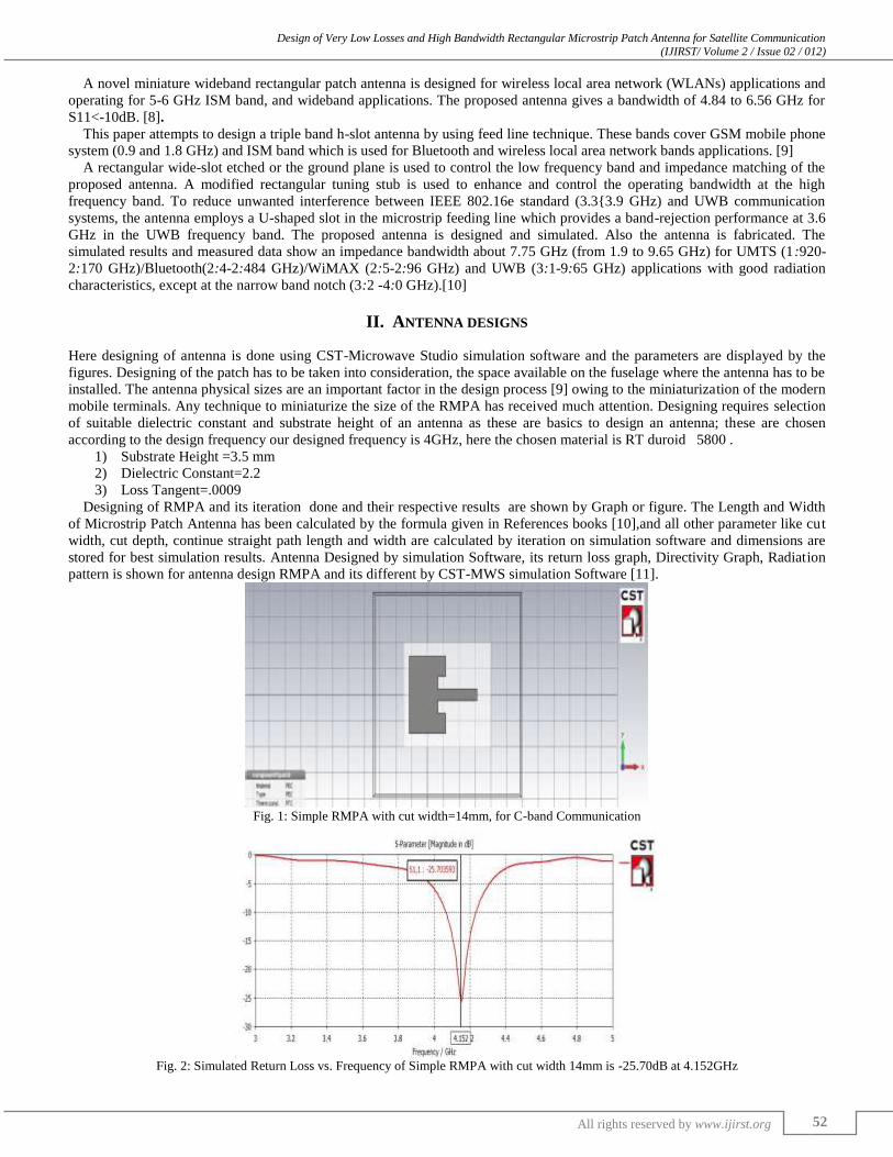
Fig. 1: Simple RMPA with cut width=14mm, for C-band Communication
Fig. 2: Simulated Return Loss vs. Frequency of Simple RMPA with cut width 14mm is -25.70dB at 4.152GHz
Design of Very Low Losses and High Bandwidth Rectangular Microstrip Patch Antenna for Satellite Communication (IJIRST/ Volume 2 / Issue 02 / 012)
All rights reserved by www.ijirst.org 53
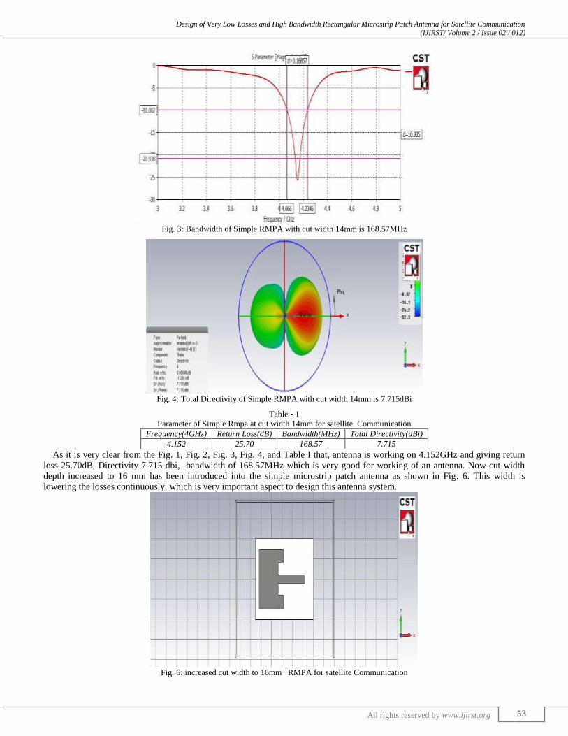
Fig. 3: Bandwidth of Simple RMPA with cut width 14mm is 168.57MHz
Fig. 4: Total Directivity of Simple RMPA with cut width 14mm is 7.715dBi
Table - 1
Parameter of Simple Rmpa at cut width 14mm for satellite Communication
Frequency(4GHz) Return Loss(dB) Bandwidth(MHz) Total Directivity(dBi)
4.152 25.70 168.57 7.715
As it is very clear from the Fig. 1, Fig. 2, Fig. 3, Fig. 4, and Table I that, antenna is working on 4.152GHz and giving return
loss 25.70dB, Directivity 7.715 dbi, bandwidth of 168.57MHz which is very good for working of an antenna. Now cut width
depth increased to 16 mm has been introduced into the simple microstrip patch antenna as shown in Fig. 6. This width is
lowering the losses continuously, which is very important aspect to design this antenna system.
Fig. 6: increased cut width to 16mm RMPA for satellite Communication

Design of Very Low Losses and High Bandwidth Rectangular Microstrip Patch Antenna for Satellite Communication (IJIRST/ Volume 2 / Issue 02 / 012)
All rights reserved by www.ijirst.org 54
Fig. 7: Simulated Return-loss of cut width 16mm Slot RMPA is 51.65dB at 4.164GHz
Fig. 8: Bandwidth of cut width=16mm RMPA is 160.41 MHz
Fig. 9.Total directivity of cut width =16mm, RMPA is 7.735dbi
Table – 2
Parameter of Rmpa at cut width of 16mm for satellite Communication Frequency(4GHz) Return-Loss(dB) Bandwidth(MHz) Total Directivity(dBi)
4.164 51.65 160.41 7.735
Design of Very Low Losses and High Bandwidth Rectangular Microstrip Patch Antenna for Satellite Communication (IJIRST/ Volume 2 / Issue 02 / 012)
All rights reserved by www.ijirst.org 55
III. CONCLUSION
The paper concludes from above figures and tables that the when cut width increases to 16mm from 14mm Antenna
characteristics has been improved like return loss are decreased,bandwidth are almost same and, due to this improvement in
parameters maximum output is achieved. In this paper improvement in return loss in great amount this will give the maximum
output and bandwidth is also increases in great extent, the great achievement on patch antenna designing system.
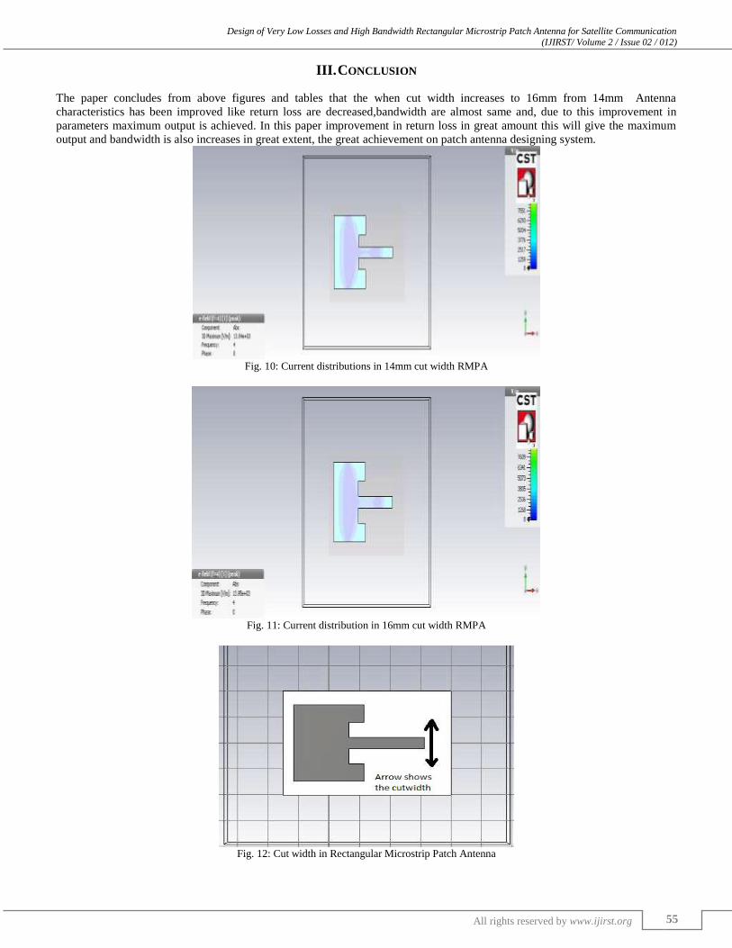
Fig. 10: Current distributions in 14mm cut width RMPA
Fig. 11: Current distribution in 16mm cut width RMPA
Fig. 12: Cut width in Rectangular Microstrip Patch Antenna

Design of Very Low Losses and High Bandwidth Rectangular Microstrip Patch Antenna for Satellite Communication (IJIRST/ Volume 2 / Issue 02 / 012)
All rights reserved by www.ijirst.org 56
IV. RESULT
Comparative study of both the antenna is done as shown, in Fig. 6 and Fig. 1 the size is reduced. from Fig. 2 and Fig. 7 the
Return-loss of antenna is decreased about 100.972%Antenna directivity is increased from7.715dbi to 7.735dbi clear from Fig. 4
and Fig. 9, antenna total efficiency are almost same as shown in figure 4 and 9, bandwidth is slightly reduced due to decrement
of losses up to 100.972%, bandwidth slightly decreases to 160.41Mhz from 168.57Mhz as shown in Fig. 3 and Fig. 8 and, all
these results can be justified from Table I and Table II .the bandwidth of these antennas are too much higher for satellite
communication this is main important advantage of this antenna ,figure 11 and figure 12 shows the current distributions in the
two different cut width antennas and figure 12 shows the illustration of cut width of the RMPA. The larger current distribution in
18mm cut width depth antenna validates the designing of RMPA
REFERENCES
[1] John D. Kraus. Antennas. 2nd Edition.McGraw Hill International, 1988.
[2] Swaraj Prasad,Mithlesh Kumar “Quad band U-Slot Microstrip Patch Antenna in International Journal of Scientific Research Engineering & Technology
(IJSRET), ISSN 2278 – 0882 Volume 3 Issue 1, April 2014 pp 145-148 [3] Ei Thae Aye , Chaw Myat New “Rectangular Microstrip Patch Antenna for RFID Application using 2.45GHz frequency range” in International Journal of
Scientific and Research Publications, Volume 4, Issue 6, June 2014
[4] Hemant Kumar Gupta,P.K.Singhal “ Patch Antennas Designs with Different Shaped Defect Ground Structure Pattern in Efficient Rectenna Design for Wireless Power Transmission” in IJECCT open access journal (Malayisa) Vol. No.3 Issue No.1.
[5] L.T. Akhil Bright,and Mrs. A. Kayalvizhi “ Design of a microstrip-fed monopole antenna with a wide slot ground plane for uwb applications” Electrical
Engineering: An International Journal (EEIJ), Vol. 1, No. 1, June 2014 [6] Vidya deshmukh & abhilasha mishra “Analysis & designing of e-shape microstrip antenna with slot for ism band” in Internatonal Journal of research in
engineering and technology Vol 2 issue 7 Jun 2014 pp 41-48
[7] Ahmed Al-Shaheen new patch antenna for ism band at 2.45 ghz at arpn Journal of Engineering and Applied Science Vol.7 issue 1 2012 [8] Mohamed Nabil Srifi*, Mourad Meloui and Mohamed Essaaidi “Rectangular Slotted Patch Antenna for 5-6GHz Applications” at International Journal of
Micorwave and Optical Technology Vol.5 No.2 march 2010
[9] Omar Noori, Jalel Chebil, Md. Rafiqul Islam and Sheroz Khan Design of a Triple-Band h Slot Patch Antenna in 2011 IEEE international RF and Microwave conference(RFM 2011),12-14 decemeber 2011 seremban, malaysia
[10] Mohamed Mamdouh M. Ali1, Ayman Ayd R. Saad2, and Elsayed Esam M. Khaled1 “A Microstrip-fed Printed Slot Antenna for 3G/Bluetooth/WiMAXand
UWB Applications with 3.6GHz Band Rejection” in PIERS Proceedings, Stockholm, Sweden, Aug. 12{15, 2013 [11] C.Balinies,“Antenna Theory”, Wiley, 2nd addition chapter -14 ISBN 0-471-59268-4., (1997).
[12] http://www.cst.com/content/products/mws/overview.aspx © 2014 CST Computer Simulation Technology