bandwidth enhancement of microstrip antenna using … · scribes the design of microstrip antenna...
TRANSCRIPT

International Journal of Scientific & Engineering Research, Volume 4, Issue 11, November-2013 ISSN 2229-5518
IJSER © 2013
http://www.ijser.org
Bandwidth Enhancement of Microstrip Antenna Using Partial Ground
Ms. Priyanka Deosarkar, Prof. Mrs. S. A. Shirsat
Abstract— Microstrip antennas have become the favorite choice of antenna designers because of advantages such as low profile, light weight,
easy fabrication and easy integration with circuits. Although microstrip antenna has several advantages, also it has several disadvantages such as
low gain and narrow bandwidth. Intensive research is going on to develop bandwidth enhancement techniques by keeping its size small. This
paper gives comparision of simple rectangular microstrip antenna and microsrip antenna with partial ground. One is the simple rectangular Mi-
crostrip antennas and another is, rectangular Microstrip antennas with modifying the ground plane is designed and simulated .This paper de-
scribes the design of Microstrip antenna resonate at frequency 2.4 GHz using coaxial feeding for high speed networks. The antenna is constructed
on material with dielectric constant of 4.4. The advantages of Microstrip antennas have made them a perfect candidate for use in the wireless
local area network (WLAN) applications. Though bound by certain disadvantages, Microstrip antennas can be tailored so they can be used in the
new high-speed WLAN systems. This project concentrates on manufacture enhancement of bandwidth of Microstrip antennas for the 2.4 GHz
ISM band. Finally, simulation is done using software HFSSv13. HFSS is employed to analyze the proposed antenna and simulated results on
return loss, input impedance, 3D radiation pattern and VSWR plot is presented.
Index Terms— Bandwidth Enhancement, Circular polarization, Microstrip antenna, VSWR, Return Loss, 3D gain, HFSSv13.
—————————— ——————————
1 INTRODUCTION
ow the world is coming closer with 3G Network & en-tering into the Networks of 4th Generation. Behind this there is big hand of Wireless Communication Systems
(WCS) and there is a very large demand by the end user for integrated wireless digital application because of its mobility. Wireless technology is one of the main areas of research in the world of communication systems today and a study of com-munication systems is incomplete without an understanding of the operation of antennas. [4]. Antennas which are used in these applications should be low profile, light weight, low volume and broad range of frequency to meet these require-ments, microstrip antenna is preferred. Microstrip antennas have several advantages compared to conventional micro-wave antennas and therefore many applications cover the broad frequency range from 100 MHz to 100 GHz. The patch can take any shape but rectangular and circular configurations are the most commonly used configuration. Microstrip patch is one of the most widely used radiators for generating circu-lar polarization. Circular polarization of microstrip antenna depends upon various patch shapes such as square, circular, pentagonal, equilateral triangular, ring.
In recent days, there has been strong demand to increase research and application interests in wirelessMultimedia sys-tems.But improvements are still required to provide higher data-rate links, for instance, the transmission of video signals. Therefore, ultra-wideband (UWB) communication systems are currently under investigation and the design of a compact wideband antenna is very essential. Demand on the wireless personal area network is increasing, such as high-speed inter-net access, video streaming, and fixed broadband wireless access system are rapidly growing up V- and W-band milli-meter-wave (MMW) applications. In the MMW band, an on-chip antenna is very attractive due to the system integration. A simple structure like dipole or monopole antenna has been achieved on the Si-based substrate in the previous literatures. An active integrated antenna (AIA) is an adaptive option for the MMW design since the chip size of the antenna decrease with frequency. So far, a few AIAs have very compact area.
To overcome the inherently narrow bandwidth of mi-crostrip antennas, various techniques have been developed to cover the entire UWB bandwidth, such as L-/F-shaped probe to feed the patch[11], modified circular patch[14], U-/V-slot monopoles[5][4],tapered slot[2], Electrically thick substrate using thick foam or air substrate, the bandwidth can be achieved up to 15% .But for thicker substrates, it is difficult to design antenna arrays in the curved surfaces (of aircraft, space craft, missiles and so on). In the papers [1][2][4], Authors have been proposed various impedance matching and feeding techniques such as quarter wave transformer, hybrid coupler for array configuration to improve the bandwidth.
The section I give introduction and related work. The sec-tion II gives antenna design and geometry
N
————————————————
Ms. Priyanka Deosarkar is currently pursuing masters’ degree program in Electronics and Telecommunication (Communication Networks) in Sinhgad college of Engineering, Vadgaon, Pune 411041.Pune University.
E-mail: [email protected]
Prof. Mrs. S. A. Shirsat is currently working as Assistant Professor at Sinhgad college of Engineering, Vadgaon, Pune 411041. Pune University
E-mail: [email protected]
452
IJSER
International Journal of Scientific & Engineering Research Volume 4, Issue 11, November-2013 ISSN 2229-5518
IJSER © 2013
http://www.ijser.org
2 ANTENNA DESIGN AND GEOMETRY
The material with dielectric constant 4.4(FR4 Epoxy) is used as backplane conductor to form Microstrip antenna. The thickness of the substrate is 1.6 mm. However, the same con-figuration when realized with other low loss substrate gives better performance. The antenna is probe fed which is the most widely used feeding method in Microstrip antenna. The patch is resonating at 2.4 GHz.
We presented first singly fed circularly polarized rectangu-lar Microstrip antennas with various configurations. To begin with, a nearly rectangular patch is designed followed by mod-ified patch in the form of four slots around the centre of patch along the axis. The patch length (L=28mm) and width (W=38mm) determines the orthogonal resonant frequencies for the fundamental TM10 mode, the L should be slightly less than λ/2, where λ is the wavelength in the dielectric medi-um.[9]
The fundamental TM10 mode implies that the field varies one λ/2 cycle along the length, and no variation along the width of the patch. A nearly rectangular MSA operating at TM10 mode can be visualized as a transmission line, because the field is uniform along the width and varies sinusoidal along the edge length. [8,9]
1.1 SIMPLE RECTANGULAR MICROSTRIP ANTENNA
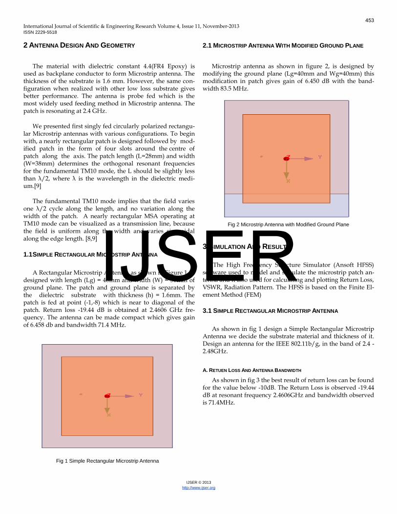
A Rectangular Microstrip Antenna, as shown in Figure 1, is designed with length (Lg) = 40mm and width (W) = 50mm of ground plane. The patch and ground plane is separated by the dielectric substrate with thickness (h) = 1.6mm. The patch is fed at point (-1,-8) which is near to diagonal of the patch. Return loss -19.44 dB is obtained at 2.4606 GHz fre-quency. The antenna can be made compact which gives gain of 6.458 db and bandwidth 71.4 MHz.
Fig 1 Simple Rectangular Microstrip Antenna
2.1 MICROSTRIP ANTENNA WITH MODIFIED GROUND PLANE
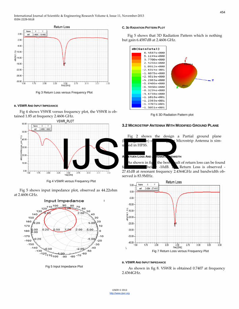
Microstrip antenna as shown in figure 2, is designed by modifying the ground plane (Lg=40mm and Wg=40mm) this modification in patch gives gain of 6.450 dB with the band-width 83.5 MHz.
Fig 2 Microstrip Antenna with Modified Ground Plane
3 SIMULATION AND RESULT
The High Frequency Structure Simulator (Ansoft HFSS) software used to model and simulate the microstrip patch an-tenna and it also used for calculating and plotting Return Loss, VSWR, Radiation Pattern. The HFSS is based on the Finite El-ement Method (FEM)
3.1 SIMPLE RECTANGULAR MICROSTRIP ANTENNA
As shown in fig 1 design a Simple Rectangular Microstrip Antenna we decide the substrate material and thickness of it. Design an antenna for the IEEE 802.11b/g, in the band of 2.4 -2.48GHz.
A. RETUEN LOSS AND ANTENNA BANDWIDTH
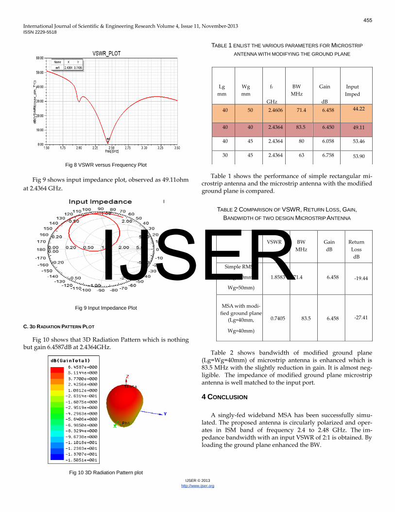
As shown in fig 3 the best result of return loss can be found for the value below -10dB. The Return Loss is observed -19.44 dB at resonant frequency 2.4606GHz and bandwidth observed is 71.4MHz.
453
IJSER
International Journal of Scientific & Engineering Research Volume 4, Issue 11, November-2013 ISSN 2229-5518
IJSER © 2013
http://www.ijser.org
Fig 3 Return Loss versus Frequency Plot
B. VSWR AND INPUT IMPEDANCE
Fig 4 shows VSWR versus frequency plot, the VSWR is ob-tained 1.85 at frequency 2.4606 GHz.
Fig 4 VSWR versus Frequency Plot
Fig 5 shows input impedance plot, observed as 44.22ohm at 2.4606 GHz.
Fig 5 Input Impedance Plot
C. 3D RADIATION PATTERN PLOT
Fig 5 shows that 3D Radiation Pattern which is nothing but gain 6.4587dB at 2.4606 GHz.
Fig 6 3D Radiation Pattern plot
3.2 MICROSTRIP ANTENNA WITH MODIFIED GROUND PLANE
Fig 2 shows the design a Partial ground plane (Lg=Wg=40mm) of Rectangular Microstrip Antenna is sim-ulated in HFSS.
A. RETUEN LOSS AND ANTENNA BANDWIDTH
As shown in fig 7 the best result of return loss can be found for the value below -10dB. The Return Loss is observed -27.41dB at resonant frequency 2.4364GHz and bandwidth ob-served is 83.9MHz.
Fig 7 Return Loss versus Frequency Plot
B. VSWR AND INPUT IMPEDANCE
As shown in fig 8. VSWR is obtained 0.7407 at frequency 2.4364GHz.
454
IJSER
International Journal of Scientific & Engineering Research Volume 4, Issue 11, November-2013 ISSN 2229-5518
IJSER © 2013
http://www.ijser.org
Fig 8 VSWR versus Frequency Plot
Fig 9 shows input impedance plot, observed as 49.11ohm
at 2.4364 GHz.
Fig 9 Input Impedance Plot
C. 3D RADIATION PATTERN PLOT
Fig 10 shows that 3D Radiation Pattern which is nothing but gain 6.4587dB at 2.4364GHz.
Fig 10 3D Radiation Pattern plot
TABLE 1 ENLIST THE VARIOUS PARAMETERS FOR MICROSTRIP
ANTENNA WITH MODIFYING THE GROUND PLANE
Table 1 shows the performance of simple rectangular mi-
crostrip antenna and the microstrip antenna with the modified ground plane is compared.
TABLE 2 COMPARISON OF VSWR, RETURN LOSS, GAIN,
BANDWIDTH OF TWO DESIGN MICROSTRIP ANTENNA
Table 2 shows bandwidth of modified ground plane (Lg=Wg=40mm) of microstrip antenna is enhanced which is 83.5 MHz with the slightly reduction in gain. It is almost neg-ligible. The impedance of modified ground plane microstrip antenna is well matched to the input port.
4 CONCLUSION
A singly-fed wideband MSA has been successfully simu-lated. The proposed antenna is circularly polarized and oper-ates in ISM band of frequency 2.4 to 2.48 GHz. The im-pedance bandwidth with an input VSWR of 2:1 is obtained. By loading the ground plane enhanced the BW.
Lg
mm
Wg
mm
fr
GHz
BW
MHz
Gain
dB
Input
Imped
Ω 40 50 2.4606 71.4 6.458 44.22
40 40 2.4364 83.5 6.450 49.11
40 45 2.4364 80 6.058 53.46
30 45 2.4364 63 6.758 53.90
VSWR
BW
MHz
Gain
dB
Return
Loss
dB
Simple RMSA
(Lg=40mm,
Wg=50mm)
1.8583 71.4 6.458 -19.44
MSA with modi-
fied ground plane
(Lg=40mm,
Wg=40mm)
0.7405 83.5 6.458 -27.41
455
IJSER

International Journal of Scientific & Engineering Research Volume 4, Issue 11, November-2013 ISSN 2229-5518
IJSER © 2013
http://www.ijser.org
ACKNOWLEDGEMENT
The authors would like to thank Prof. Mrs. S. A. Shirsat, Sinhgad College of Engineering, Pune, and Dr. R. S. Kawitkar, Sinhgad college of engineering, Pune and Dr. Shankar B. De-osarkar, Principal, VPCOE, Baramati for his encourage-ment and valuable guidance for this current research topic and for making software required and laboratory available.
REFERENCECS
[1] Ali A., Dheyab Al-Sajee, “Enhancement Bandwidth Of Microstrip An-
tenna Using Tapered Single Slot,” Asian Research Publishing Network
(ARPN) Journal of Engineering and Applied Science, VOL.7, NO. 1, Janu-
ary 2012.
[2] Thakare V.V., Singhal P. K. “Bandwidth Analysis By Introducing Slots
in Microstrip Antenna Design”, Progress in Electromagnetics Research
Manual, VOL.9, pp107-122,2009.
[3] Shi.Wein Que & Quen Xue, “A Y-Shaped Stub Proximity Coupled V-
Slot Microstrip Antenna,” IEEE Antennas and Wireless Propagation Let-
ters, VOL. 6, 2007.
[4] Raja Abdullah, D. Yoharaaj,”Bandwidth En-hancement For Microstrip Antenna In Wireless Application”, Modern Applied Science Journal, VOL. 7, NO. 6, November 2006.
5] ] Ricky Chair, Chi-Lun Mak, Kai-Fong Lee, Kwai-Man Luk & Ahmed A.
Kishk, “Miniature Wide-Band Half U-Slot and Half E-Shaped Patch
Antennas,” IEEE Transactions on Antennas And Propagation, VOL. 53,
NO. 8, AUGUST 2005.
[6] Jongkuk Park, Hyung-gi Na, Seung-hun Baik, “Design of a Modified L-
Probe Fed Microstrip Patch Antenna,” IEEE Antennas And Wireless Prop-
agation Letters, VOL. 3, 2004.
[7] Rajeshwar Lal Dua, Himanshu Singh, Neha Gambhir, “2.45 GHz Mi-
crostrip Patch Antenna with Defected Ground Structure for Bluetooth”,
in International Journal of Soft Computing and Engineering (IJSCE)
ISSN: 2231-2307, Volume-1, Issue-6, January 2012.
[8] Anil B. Nandgaonkar and Shankar B. Deosarkar, Successful “De-
sign of Singly-fed Wideband and High Gain Micro Strip Anten-
na”,IETE Journal of Research,Volume-55,No.6 November-December2007
[9] Constantine A. Balanis, “Antenna Theory Analysis & Design,” A John
Wiley & Sons, Inc., Publication 2005, ISBN: 0-471-66782-x (3rd Edition)
[10] Girish Kumar and K.P. Ray, “Broadband Microstrip Antennas,” Lon-
don, Boston Artech House 2003.
[11] Garg R., Bhartia P. and Ittipiboon A, “Microstrip Antenna Design
Handbook,” Bartech House, Inc 2001.
[12] K L Wong, “Compact and broadband Microstrip Antennas”,
NewYork: Wiley and Sons, Inc.; pp.295-8., 2002.
456
IJSER