design of high voltage ac/ac electrochemical capacitors in...
TRANSCRIPT
Poznan University of Technology
Faculty of Chemical Technology
Institute of Chemistry and Technical Electrochemistry
Field of study: Chemical Technology
Paula Ratajczak
DESIGN OF HIGH VOLTAGE
AC/AC ELECTROCHEMICAL CAPACITORS
IN AQUEOUS ELECTROLYTE
Pr o jek t o wan ie w yso ko na p ię c io w yc h ko nd e nsa t o r ó w
e lek t r o che mic z nyc h ,
pr acu ją c yc h w e lek t r o l it a c h wo d nyc h
DOCTORAL DISSERTATION
Promoter:
prof. François Béguin
Poznań 2015

D e s i g n o f h i g h v o l t a g e A C / A C e l e c t r o c h e m i c a l c a p a c i t o r s i n a q u e o u s e l e c t r o l y t e
Paula Ratajczak P a g e 2
Badania do niniejszej pracy prowadzone były przy wsparciu przez projekt ECOLCAP
realizowany w ramach Programu Welcome, finansowanego przez Fundację Nauki Polskiej
(FNP)zgodnie z Działaniem 1.2. „Wzmocnienie potencjału kadrowego nauki”, Programu
Operacyjnego Innowacyjna Gospodarka wspieranego przez Unię Europejską
Kierownik projektu: Profesor François Béguin
This thesis’ research was supported by ECOLCAP project funded in the frame of the
Welcome Programme implemented by the Foundation for Polish Science (FNP) within
the Measure 1.2. ‘Strengthening the human resources potential of science’, of the
Innovative Economy Operational Programme supported by European Union.
Project leader: Professor François Béguin
D e s i g n o f h i g h v o l t a g e A C / A C e l e c t r o c h e m i c a l c a p a c i t o r s i n a q u e o u s e l e c t r o l y t e
Paula Ratajczak P a g e 3
Część praca badawczej została wsparta przez projekt LIDER finansowany przez
Narodowe Centrum Badań i Rozwoju LIDER/018/513/L-4/12/NCBR/201„Kondensator
elektrochemiczny o wysokiej gęstości energii i mocy operujący w roztworach
sprzężonych par redoks:
Kierownik projektu: dr inż. Krzysztof Fic
A port of the research work was supported by the LIDER project funded by the National
Centre for Research and Development (NCBiR) LIDER/018/513/L-4/12/NCBR/201
"Electrochemical capacitor with high energy density and power operating in coupled
redox couples solutions”.
Project leader: Dr Eng. Krzysztof Fic

D e s i g n o f h i g h v o l t a g e A C / A C e l e c t r o c h e m i c a l c a p a c i t o r s i n a q u e o u s e l e c t r o l y t e
Paula Ratajczak P a g e 4
I am sincerely grateful to my supervisor,
Prof. François Béguin,
for his guidance and all the efforts he put in my PhD work
I am also greatly thankful to Dr hab Eng Krzysztof Jurewicz,
for our collaborative work on carbon materials and supercapacitors
It is also a great pleasure to thank
Prof. Dr hab Elżbieta Frąckowiak,
and Dr Eng Krzysztof Fic for helping me to develop the skills and knowledge
in electrochemistry and carbon materials
My sincere gratitude is also dedicated
to all the ECOLCAP group members, especially, Dr Qamar Abbas,
M.Sc Eng Piotr Skowron
and M.Sc Eng. Paweł Jeżowski for their experimental support

D e s i g n o f h i g h v o l t a g e A C / A C e l e c t r o c h e m i c a l c a p a c i t o r s i n a q u e o u s e l e c t r o l y t e
Paula Ratajczak P a g e 5
TABLE OF CONTENTS
INTRODUCTION _____________________________________________________ 9
CHAPTER I
LITERATURE REVIEW ON ELECTROCHEMICAL CAPACITORS __________ 16
I.1. General properties of electrochemical capacitors______________________ 17
1.1. The electrical double-layer models ______________________________________________ 17
1.2. Operation principle of an EDLC _______________________________________________ 19
1.3. Energy and power of electrochemical capacitors ___________________________________ 21
1.4. Pseudo-capacitive contribution _________________________________________________ 23
I.2. Electrode materials for electrochemical capacitors ____________________ 25
2.1. Commonly used carbon materials_______________________________________________ 25
2.2. Redox-active electrode materials _______________________________________________ 31
I.3. Structural and textural properties of activated carbons__________________ 31
3.1. Manufacturing of porous carbons _______________________________________________ 31
3.2. Surface functional groups on carbons ____________________________________________ 33
3.3. Effect of porous texture of activated carbons on the capacitive performance______________35
I.4. Electrolytes for electrochemical capacitors___________________________ 39
4.1. Aqueous electrolytes_________________________________________________________ 40
4.2. Organic electrolytes _________________________________________________________ 48
4.3. Ionic liquids _______________________________________________________________ 49
I.5. Conclusion ___________________________________________________ 51
CHAPTER II
ELECTROCHEMICAL TECHNIQUES
FOR ELECTROCHEMICAL CAPACITORS INVESTIGATION _______________ 53
II.1. Cyclic voltammetry ____________________________________________ 54

D e s i g n o f h i g h v o l t a g e A C / A C e l e c t r o c h e m i c a l c a p a c i t o r s i n a q u e o u s e l e c t r o l y t e
Paula Ratajczak P a g e 6
II.2. Constant current charging/discharging ______________________________ 56
II.3. Impedance spectroscopy _________________________________________ 58
II.4. Accelerated ageing test __________________________________________ 60
CHAPTER III
STATE OF HEALTH OF AQUEOUS ELECTROCHEMICAL CAPACITORS
WITH STAINLESS STEEL CURRENT COLLECTORS
UNDER ACCELERATED AGEING _____________________________________ 63
III.1. High voltage ageing assessment of AC/AC electrochemical capacitors
in lithium sulfate electrolyte ______________________________________ 65
1.1. Exploring the high operating voltage of AC/AC electrochemical capacitors
in lithium sulfate electrolyte ___________________________________________________ 65
1.2. Degradation of ECs electrochemical performance under accelerated ageing ______________ 67
III.2. Factors contributing to ageing in aqueous electrolyte __________________ 74
2. 1. Oxidation of carbon electrodes and corrosion of stainless steel current collectors __________ 74 2.1.1. Post-floating analysis of ECs by electrochemical techniques __________________________ 74 2.1.2. Post-floating analyses on carbon electrodes _______________________________________ 78 2.1.3. Effect of temperature on ageing ________________________________________________ 82
2.2. Gas evolution during floating __________________________________________________ 83
III.3. Conclusion ___________________________________________________ 87
CHAPTER IV
STRATEGIES FOR IMPROVING THE LONG TIME PERFORMANCE
OF HIGH VOLTAGE CAPACITORS IN AQUEOUS ELECTROLYTES ________ 89
IV.1. Corrosion reduction of positive current collector ______________________ 90
1.1. Alternative nickel current collectors _____________________________________________ 91
1.2. Improvement of the current collector/electrode interface _____________________________ 95 1.2.1. Carbon electrodes glued to stainless steel current collectors __________________________ 95 1.2.2. Nickel foil substrate _________________________________________________________ 97 1.2.3. Carbon conductive sub-layer _________________________________________________ 100
1.3. Addition of corrosion inhibitor ________________________________________________ 103

D e s i g n o f h i g h v o l t a g e A C / A C e l e c t r o c h e m i c a l c a p a c i t o r s i n a q u e o u s e l e c t r o l y t e
Paula Ratajczak P a g e 7
IV.2. Shifting of electrodes operating potentials __________________________ 109
2.1. Asymmetric configuration ___________________________________________________ 109
2.2. Current collectors coupling___________________________________________________ 117
IV.3. Conclusion __________________________________________________ 122
CHAPTER V
TOWARDS A NEW CONCEPT
OF HIGH VOLTAGE AC/AC CAPACITOR IN AQUEOUS ELECTROLYTES__ 124
III.1. The new concept of high voltage cell in aqueous electrolytes ___________ 125
III.2. Extension of voltage range by electrodes asymmetry _________________ 134
2.1 Adjustment of electrodes potential window by increasing m+/m- ______________________ 134
2.2. Voltage extension by use of different carbon electrodes ____________________________ 136
III.3. Conclusion __________________________________________________ 138
GENERAL CONCLUSION ____________________________________________ 138
EXPERIMENTAL ANNEX____________________________________________ 142
A.1. Cell construction _________________________________________________ 143
1.1. Materials and chemicals _____________________________________________________ 143
1.2. Preparation of electrodes ____________________________________________________ 145
1.3. Cells configurations ________________________________________________________ 146
A.2. Electrochemical characterization ____________________________________ 147
A.3. Physico-chemical and surface characterization _________________________ 147

D e s i g n o f h i g h v o l t a g e A C / A C e l e c t r o c h e m i c a l c a p a c i t o r s i n a q u e o u s e l e c t r o l y t e
Paula Ratajczak P a g e 8
REFERENCES ______________________________________________________ 149
SCIENTIFIC ACHIEVEMENTS________________________________________ 165
ABSTRACT ________________________________________________________ 172
STRESZCZENIE ____________________________________________________ 175

D e s i g n o f h i g h v o l t a g e A C / A C e l e c t r o c h e m i c a l c a p a c i t o r s i n a q u e o u s e l e c t r o l y t e
Paula Ratajczak P a g e 9
INTRODUCTION

D e s i g n o f h i g h v o l t a g e A C / A C e l e c t r o c h e m i c a l c a p a c i t o r s i n a q u e o u s e l e c t r o l y t e
Paula Ratajczak P a g e 10
Energy management has a deep influence in the humans’ everyday life,
considering social, economic, ecological and political aspects. During the last 50 years,
the world energy consumption, mainly based on petroleum-based fuels (oil, coal and
natural gas), has considerably increased (Figure 1), due to industrial development of the
western countries after the 2nd
World War, accompanied by improving wealth in
emerging markets and growth of the human population, especially in China and India.
Although renewable energy and nuclear power are the world fastest-growing energy
sources in the recent years (each increasing around by 2.5% per year), fossil fuels still
share more than 80% of the global energy consumption [1].
Figure 1 World energy consumption (based on [2]).
Over the past decade, a general awareness appeared that fossil fuel consumption
presents severe drawbacks, such as an important depletion of reserves and the emission
of noxious gases leading in particular to the greenhouse effect and to associated
temperature increase of the planet. The industry is partly able to handle with some of
these problems, by introducing modern solutions, such as reducing emissions by placing
catalysts in the exhaust systems of vehicles and in the chimneys of power plants.
Notwithstanding, if fossil fuels would remain the only power source for the future, the
forthcoming crunch of their availability would lead to economic dislocations and
serious political problems. Therefore, the incoming environmental and economic crisis
predictions have suggested to develop strategies for improving energy efficiency (e.g.,

D e s i g n o f h i g h v o l t a g e A C / A C e l e c t r o c h e m i c a l c a p a c i t o r s i n a q u e o u s e l e c t r o l y t e
Paula Ratajczak P a g e 11
by improving buildings thermal insulation, by introducing hybridization in
transportation systems, etc.) and for introducing renewables (sun and wind) in the
energy mix. Due to the intermittent character of the ‘clean’ resources, to ensure a real-
time balance of electricity supply to the demand over various time scales, the renewable
technologies require energy-storage devices in order to adapt the energy delivery to the
demand.
Figure 2 shows that energy can be stored via physical and chemical processes
and further delivered in the form of electricity. The main systems are based on gravity
(pumped hydro power storage), Compressed Air Energy Storage (CAES), kinetic
energy (fly wheel), magnetic (Superconducting Magnetic Energy Storage (SMES),
electric field (Electrical Double-Layer Capacitors (EDLCs)) and electrochemical
reactions (batteries). “Pumped-hydro” is the most traditional way of storing energy on a
large scale, by utilizing the excess of electric power to pump water from a lower to a
higher-level reservoir. During the periods of high electricity demand, water is released
to the lower elevation inducing the rotation of turbines and electricity generation.
Notwithstanding, this technology is geographically constrained and requires specific
locations with a sufficient elevation difference between the two reservoirs, which makes
the pumped-hydro plants non-transferable. A second interesting technology for large-
scale storage uses underground air compression (CAES) and requires specific geologic
characteristics. However, the required equipment to store and extract the energy,
including compressors and turbine-generators, generates high cost of the CAES plants.
Moreover, CAES generates heat in excess during compression, which reduces the yield
of the process.
A technology which tends to be well-suited to ensure a real-time balance of
electricity supply to the demand over various time scales is based on flywheels, which
feature in a rapid response time. However, due to the high rotation speed of the rotor,
for long-term performance, they require maintenance, and for this reason, are still
considered to be not completely safe.
Since capital cost and environmental impact are a major barrier to deployment of
energy storage, magnetic energy storage (SMES) seems to be a more economic
technology than, e.g., pumped hydro and CAES. However, a typical SMES system
includes a coil of superconducting material, a power conditioning system and

D e s i g n o f h i g h v o l t a g e A C / A C e l e c t r o c h e m i c a l c a p a c i t o r s i n a q u e o u s e l e c t r o l y t e
Paula Ratajczak P a g e 12
cryogenically cooled refrigerators, determining the final price of the equipment.
Moreover, SMES is not yet available on a large scale, but only for power application on
a micro scale.
Figure 2 Energy storage systems which rely on physical and chemical processes.
At present, electrochemical systems (secondary batteries, electrochemical
capacitors) appear as the most suited and flexible devices to adapt the electricity
delivery to the demand, provided that the amount of energy involved is not extremely
high. The storage batteries can convert the electrical work generated by, e.g., solar cells,
into chemical free energy needed to force the reaction in a non-spontaneous direction.
Since rechargeable batteries (lead–acid, Ni-Cd, Ni-MH, Li-ion) appear in many
different shapes and sizes, besides the grid energy storage applications, they are also

D e s i g n o f h i g h v o l t a g e A C / A C e l e c t r o c h e m i c a l c a p a c i t o r s i n a q u e o u s e l e c t r o l y t e
Paula Ratajczak P a g e 13
designed for individual customers to be used in automobile starters, portable devices,
light vehicles and power supplies. Due to the chemical character of the operation, the
discharge rate of batteries is limited and energy is lost due to the internal resistance of
the cell components. Moreover, the concentration of a relatively large amount of
chemical energy into a small package may result in hazardous events, such as numerous
cases of fire and explosion in case of Li-ion batteries.
Electrochemical capacitors, due to their simple construction and the electrostatic
character of energy storage (Figure 2), are characterized by a fast response time, as
compared to the other available devices. As they apply high surface area porous carbon
electrodes immersed in an electrolytic solution, they store several orders of magnitude
higher energy than conventional dielectric capacitors. The most commonly developed
systems at the industrial scale are electrical-double layer capacitors (EDLCs), which
store the electrical charge in the Helmholtz double-layer. Due to the specific principle of
operation, where a nanoscale layer of ions from the electrolyte is attracted to the surface
of a polarized electrode material, ECs display high power density of 15 kW kg-1
when
compared to 2 kW kg-1
offered by, e.g., Li-ion batteries which store the charge through
electrochemical redox reactions. Therefore, ECs are adapted for high power applications
in automotive industry, opening emergency doors of aircrafts, regenerative braking and
stop-start technology in vehicles or power buffer in electric drive train. Moreover, they
have a high cycle life of more than 1,000,000 charge/discharge cycles. However, due to
the electrostatic charge storage mechanism, ECs store lower amounts of energy (5–8
Wh kg-1
) than, e.g., Li-ion batteries (up to 180 Wh kg-1
). Therefore, an important
research attention is focused on enhancing their energy density, while realizing safe,
environmentally friendly and cheap systems.
Since the energy density of ECs strongly depends on the applied maximum
voltage, most of the industrial devices are based on organic electrolytes, although
environment unfriendly and unsafe, which allow reaching 2.7 – 2.8 V. Aqueous
electrolytes such as H2SO4 and KOH have been also investigated for high power
systems, but unfortunately voltage must be limited to less than 1 V in order to avoid
electrolyte decomposition. Lately, it has been demonstrated by our research team that,
by employing aqueous alkali sulfate and gold current collectors, voltage up to 2 V can
be reached, due to a high over-potential of hydrogen evolution at the negative electrode.
D e s i g n o f h i g h v o l t a g e A C / A C e l e c t r o c h e m i c a l c a p a c i t o r s i n a q u e o u s e l e c t r o l y t e
Paula Ratajczak P a g e 14
Taking into account the numerous advantages of water-based media over the
organic ones, such as high conductivity, low cost, safety in operation and environmental
friendliness, the ultimate aim of this doctoral dissertation is to develop a carbon-based,
environmentally friendly and low-cost electrochemical capacitor (EC) operating in an
aqueous electrolyte with cheap current collectors. To pursue this objective, the
undertaken research requires considering and facing some obstacles which cause the
cell performance to fade and reliability of the EC to decline. The perturbation
phenomena occurring during long time operation of the capacitor are essentially related
to aqueous electrolyte decomposition under high voltage operation, which can lead to
oxidation of AC electrodes and/or internal pressure evolution and corrosion of metallic
current collectors. Overall, the dissertation is divided into five chapters.
Chapter I is a literature review presenting the state-of-art on AC-based
electrochemical capacitors. The operation principle and general properties of electrical
double-layer capacitors (EDLCs) are described, and the common electrode materials
employed for these devices are briefly introduced. The influence of structural and
textural properties of carbons on the performance of electrochemical capacitors is
summarized, with a special attention to the effect of porous texture on the capacitive.
ECs based on organic electrolytes, ionic liquids and aqueous media are critically
compared, with a special emphasis placed on neutral aqueous solutions. Finally, in order
to outline the pathway for the performed investigations, the drawn conclusions contain
issues which still require to be resolved for improving high-voltage operation of carbon
based electrochemical capacitors, while utilizing cheap stainless steel or nickel
collectors and aqueous electrolytes.
To attain information about the performance of electrochemical capacitors,
chapter II presents a survey of the electrochemical techniques used in our investigations.
In order to accelerate ageing of the analyzed devices, a test (so-called ‘floating’),
initially developed by industry for systems with organic electrolyte, has been
implemented and validated during our research on ECs in aqueous media.
The further parts of the dissertation are dedicated to attempts for extending the
operating voltage of carbon-based ECs. The properties and performance of
environmentally friendly AC/AC electrochemical capacitors using neutral salt aqueous
electrolytes, e.g., essentially lithium sulfate, with cheap current collectors are presented

D e s i g n o f h i g h v o l t a g e A C / A C e l e c t r o c h e m i c a l c a p a c i t o r s i n a q u e o u s e l e c t r o l y t e
Paula Ratajczak P a g e 15
in chapter III. Since all the previous works with promising neutral sulfate electrolytes
were conducted with expensive gold collectors, chapter III identifies the possible
perturbation phenomena which occur during long-term operation in aqueous solution.
The actual effect of operating voltage on the state-of-health (SOH) of the device,
evaluated by measuring cell capacitance and resistance evolution together with internal
pressure evolution, is presented. The changes of physicochemical and surface properties
of the cells’ constituents after long time operation, such as modifications of surface
functionality and porosity of the carbon-based electrodes and corrosion of stainless steel
current collectors are disclosed.
The strategies proposed in chapter IV to improve the long time performance of
AC/AC electrochemical capacitors in the neutral salt aqueous electrolyte are particularly
intended to reduce the corrosion of stainless steel collectors and decrease its destructive
effect on ECs operation. The undertaken tactics involve the replacement of the
corrodible steel current collectors, the protection of the active material/collector
interface and the addition of sodium molybdate corrosion inhibitor to lithium sulfate
electrolyte. Cells with asymmetric configuration of electrodes and coupled kinds of
current collectors are presented in the second part of chapter IV to avoid the
decomposition of aqueous electrolyte by shifting the operating electrodes potentials to
lower values.
Chapter V introduces a new concept of AC / AC cell using potassium hydroxide
and sodium sulfate as catholyte and anolyte, respectively, and a cationic exchange
membrane. Due to the pH difference between the two electrolytes, the cell can operate
at higher voltage than the thermodynamic stability limit of water, e.g., 1.23 V. The
effect of cell asymmetry, either by electrodes mass balancing or by use of different ACs,
is critically discussed with regard to fit the electrodes potential extrema within the
thermodynamic limits of water oxidation and hydrogen evolution. Besides, the proof-of-
concept allows a better understanding of the over-potential origin at the negative
electrode of AC/AC capacitors in neutral aqueous electrolytes.
Finally, the manuscript ends with a general conclusion and perspectives for
future research in the directions investigated and presented in this dissertation.

D e s i g n o f h i g h v o l t a g e A C / A C e l e c t r o c h e m i c a l c a p a c i t o r s i n a q u e o u s e l e c t r o l y t e
Paula Ratajczak P a g e 16
CHAPTER I
LITERATURE REVIEW
ON ELECTROCHEMICAL CAPACITORS
D e s i g n o f h i g h v o l t a g e A C / A C e l e c t r o c h e m i c a l c a p a c i t o r s i n a q u e o u s e l e c t r o l y t e
Paula Ratajczak P a g e 17
This chapter presents an overview on electrochemical capacitors literature
appeared during the last decades. After a short introduction about the operation
principle and general properties of electrical double-layer capacitors (EDLCs), the
review will be focused on the fundamental role played by porous carbons and
electrolytes on the electrochemical performance of EDLCs. The effect of pore size on
the electrical double-layer capacitance (Cdl) and the strategies to adjust the pore size to
the size of electrolyte ions will be emphasized. Particular attention will be paid to the
ways by which the researchers exploit the potentialities of electrolytic solutions and
carbons to increase the energy density by capacitance and voltage enhancement.
Electrolytes with extended stability window which are designed and customized for ECs
will be presented, with a special emphasis on aqueous media. The sources of
capacitance enhancement through faradaic contributions arising from oxygenated
functional groups on the surface of carbons, redox-active electrode materials,
electrochemical hydrogen storage and finally redox-active electrolytes will be also
discussed.
On the basis of this literature review, the chapter finishes with a conclusion
introducing the consecutive parts of the thesis, and emphasizing issues required to be
improved for designing a high voltage ecologically friendly capacitor in salt aqueous
electrolyte.
I.1. General properties of electrochemical capacitors
Electrochemical capacitors store energy in an electrical double-layer by
electrostatic interaction at the interface created between the conductive solid material
and the electrolyte [3, 4]. Contrary to conventional capacitors (such as aluminum
electrolytic capacitors) which contain a dielectric material sandwiched between two
electrodes facing each other, EDLCs use the electrical double-layer in their function.
1.1. The electrical double-layer models
Over the last two centuries, scientists have developed various models of the EDL
defining how ions from the electrolyte aggregate at the surface of polarized electrodes
and in their vicinity. Helmholtz was the first to describe the phenomena which occur at
the solid conductor-electrolyte boundary, and suggested that the interface consists of

D e s i g n o f h i g h v o l t a g e A C / A C e l e c t r o c h e m i c a l c a p a c i t o r s i n a q u e o u s e l e c t r o l y t e
Paula Ratajczak P a g e 18
two electrical layers which are: (i) electrons at the surface of the electrode, (ii) and a
monolayer of ions in the electrolytic solution [5].
One of the shortcomings of the Helmholtz model was the assumption of
stationary conditions where ions accumulate on the electrode surface. It did not take into
account that, due to their motion, ions are not only compacted at the surface of the
electrode, but form a diffuse space charge. Therefore, in the 1900’s Gouy and Chapman
formulated a model according to which the capacitance depends also on the applied
potential and ions concentration n [6], and is expressed by the equation (1):
𝑪𝑮𝑪 =𝜺𝜿
𝟒𝝅𝒄𝒐𝒔𝒉
𝒛
𝟐 (1)
where 𝜅 is the Debye-Hückel length [m] described in equation (2):
𝜿 = √𝟖𝝅𝒏𝒆𝟐𝒛𝟐
𝜺𝒌𝑻 (2)
z - the valency of ions, n - the number of ions per cm3, T- the absolute temperature [K],
and k – the Boltzmann constant (1.3806488 10-23
J K-1
).
More than twenty years later, Stern included in his model both a compact and a
diffuse layer [7], while Grahame divided this combined Stern layer into two regions [8]:
(i) a layer of adsorbed ions at the surface of the electrode, referred to as the inner
Helmholtz plane (IHP) (ii) and an outer Helmholtz plane (OHP) formed by the diffuse
ions in the vicinity of the electrode surface. From the Grahame model, the capacitance C
of the double-layer is described by equation (3):
𝟏
𝑪𝑮=
𝟏
𝑪𝑯+
𝟏
𝑪𝑮𝑪 (3)
with 𝐶𝐻, which corresponds to the specific capacitance of the Helmholtz’ compact
double-layer, and 𝐶𝐺𝐶 which results from the diffuse layer described by Gouy and
Chapman.
The currently used model (BMD model) of the electrical double-layer was
described by Bockris, Devanathan and Muller [9], who proposed that a water layer is

D e s i g n o f h i g h v o l t a g e A C / A C e l e c t r o c h e m i c a l c a p a c i t o r s i n a q u e o u s e l e c t r o l y t e
Paula Ratajczak P a g e 19
present at the surface of the electrode and some other water molecules are displaced by
specifically adsorbed ions (e.g., redox ions) which contribute to the pseudocapacitance.
The BMD model may be extended to charge-transfer reactions occurring in organic
electrolytes with polar solvents, e.g., acetonitrile (AN), contributing to the potential
drop across the electrode/electrolyte plane. As presented on the example of a negatively
polarized electrode (Figure 3), the inner Helmholtz plane (IHP) passes through the
centers of the specifically adsorbed ions and solvent molecules, which are oriented
parallel to the electric field. Then, the outer Helmholtz plane (OHP) passes through the
solvated ions centers, which are outside the IHP. Behind the outer Helmholtz plane,
there is a diffuse layer region.
Figure 3 Schematic representation of the BMD double-layer model on a negatively
polarized electrode (based on [9]).
1.2. Operation principle of an EDLC
In general, EDLCs are made from two identical electrodes made from a porous
material (the most commonly carbon) coated on a current collector and separated by a
porous membrane soaked with the electrolyte. When a device is connected to a power

D e s i g n o f h i g h v o l t a g e A C / A C e l e c t r o c h e m i c a l c a p a c i t o r s i n a q u e o u s e l e c t r o l y t e
Paula Ratajczak P a g e 20
supply the ions from the electrolyte aggregate on the surface of positively and
negatively polarized electrodes (Figure 4). As energy accumulation proceeds during
charging, the device is equivalent to two capacitors in series of capacitance C+ and C-
and resistance Rf+ and Rf-. The electrical double-layer capacitance of each electrode Cdl
is given by formula (4) [3]:
𝑪𝒅𝒍 =𝜺𝒓𝜺𝟎𝑺
𝒅 (4)
where S is the surface area of the electrode/electrolyte interface, εr - the relative
permittivity of the electrolyte, ε0 - vacuum permittivity (ε0= 8.854·10−12
F m-1
), d - the
EDL thickness.
.
Figure 4 Schematic representation of the charged state of a symmetric electrical double-
layer capacitor using porous carbon electrodes and its simplified equivalent circuit [10].
Even in a symmetric capacitor, due to the different size of cations and anions in
the electrolyte, the two electrodes display different capacitance values. Due to the series
equivalent circuit, the capacitance C of the total system is given by equation (5):

D e s i g n o f h i g h v o l t a g e A C / A C e l e c t r o c h e m i c a l c a p a c i t o r s i n a q u e o u s e l e c t r o l y t e
Paula Ratajczak P a g e 21
𝟏
𝑪=
𝟏
𝑪++
𝟏
𝑪− (5)
According to this relationship, the electrode with the smallest capacitance determines
the capacitance of the system.
1.3. Energy and power of electrochemical capacitors
The stored energy is directly related to ECs’ capacitance C and operating
voltage window U, according to equation (6):
𝑬 =𝟏
𝟐𝑪𝑼𝟐
(6)
Likewise, the maximum power density also depends on the applied voltage and is given
by formula (7):
𝑷 =𝑼𝟐
𝟒𝑹𝒔 (7)
with Rs which states for the equivalent series resistance (ESR) of the device. During the
charging and discharging processes, as the charges pass, the EDL flows to and from the
electrolyte/electrode interface, and electrical losses take place. The main contributions
to ESR come from [11]:
• electrolyte resistance;
• electrode material resistance;
• electrode/current-collector interfacial resistance;
• ionic (diffusion) resistance of: (i) ions reaching small pores; (ii) ions moving
through the separator.
In order to customize energy storage devices for a wide range of applications,
energy and power are plotted versus each other in a so-called Ragone plot. Figure 5
shows the significantly large area covered by the ECs, which can deliver more power
(up to 15 kW kg-1
) than redox systems such as Li-ion batteries (up to 2 kW kg-1
) [12].
However, the specific energy reached by ECs is much lower than for Li-ion batteries,
(5–8 Wh kg-1
compared to up to 180 Wh kg-1
, respectively) [13].

D e s i g n o f h i g h v o l t a g e A C / A C e l e c t r o c h e m i c a l c a p a c i t o r s i n a q u e o u s e l e c t r o l y t e
Paula Ratajczak P a g e 22
Figure 5 Ragone plot of various electrochemical energy storage systems (adapted from
[14]).
The diagonal dashed lines in Figure 5 are obtained by dividing the energy
density by power, and inform how fast the energy can be distributed. This time constant
of the device τ reveals the electrical losses during the charge storage, and is related to
the equivalent series resistance Rs and capacitance of the system C according to formula
(8):
𝝉 = 𝑹𝒔𝑪 (8)
As seen in Figure 5, the charging/discharging process of EDLCs is very fast; this is due
to the purely physical character of the storage mechanism in the electrical double-layer.
D e s i g n o f h i g h v o l t a g e A C / A C e l e c t r o c h e m i c a l c a p a c i t o r s i n a q u e o u s e l e c t r o l y t e
Paula Ratajczak P a g e 23
Since EDLCs are able to deliver all the stored energy within few seconds, they are
particularly adapted for applications which require energy pulses during short periods of
time, e.g., electric and hybrid vehicles, cranking of diesel engines and renewable energy
harvesting, tramways, buses, cranes, forklifts, wind turbines, electricity load leveling in
stationary and transportation systems, in opening emergency doors of aircrafts, etc. [12,
15].
Notwithstanding, the charge/discharge mechanism in EDLCs is fully reversible,
with efficiency close to 100%. Therefore, the commercially available devices display a
high cycle life of more than 1,000,000 charge/discharge cycles [16].
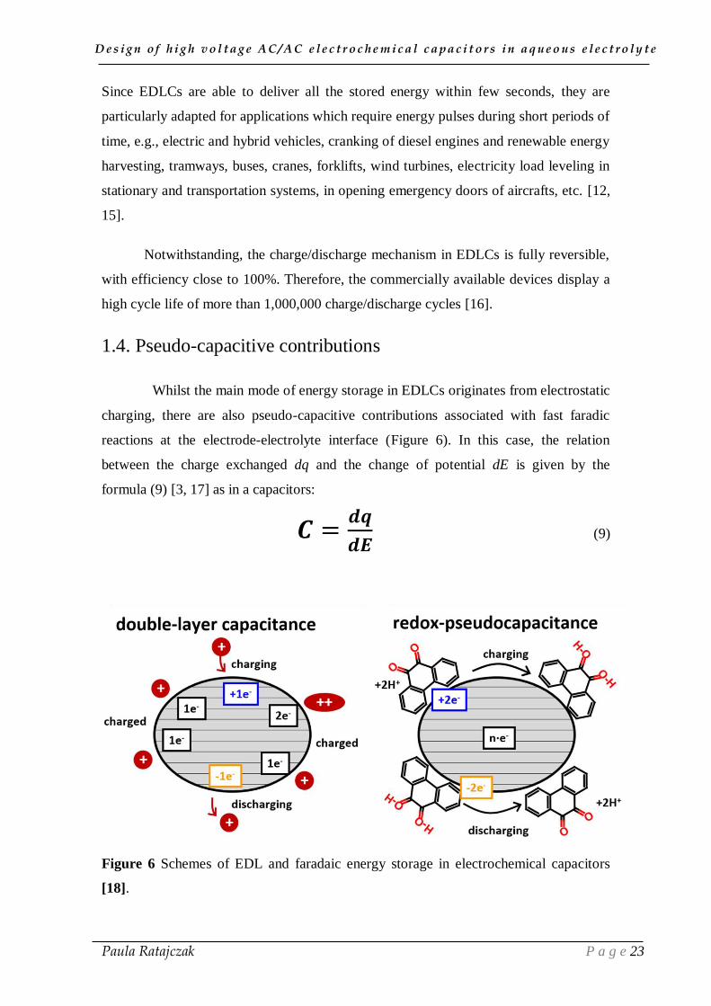
1.4. Pseudo-capacitive contributions
Whilst the main mode of energy storage in EDLCs originates from electrostatic
charging, there are also pseudo-capacitive contributions associated with fast faradic
reactions at the electrode-electrolyte interface (Figure 6). In this case, the relation
between the charge exchanged dq and the change of potential dE is given by the
formula (9) [3, 17] as in a capacitors:
𝑪 =𝒅𝒒
𝒅𝑬 (9)
Figure 6 Schemes of EDL and faradaic energy storage in electrochemical capacitors
[18].
D e s i g n o f h i g h v o l t a g e A C / A C e l e c t r o c h e m i c a l c a p a c i t o r s i n a q u e o u s e l e c t r o l y t e
Paula Ratajczak P a g e 24
The pseudo-capacitive contributions are mainly associated with, e.g., redox
reactions of electroactive species and electrosorption of nascent hydrogen or metal
atoms (underpotential deposition). The contribution to capacitance from redox reactions
comes from faradaic electron transfer involving an electrochemically active material
and/or electrolyte species at the surface of an electrode. In the equilibrium state, the
value of potential E is described by the Nernst equation (10) [19]:
𝑬 = 𝑬𝟎 −𝑹𝑻
𝒛𝑭 𝒍𝒏
𝒂𝒐𝒙
𝒂𝒓𝒆𝒅 (10)
where E0
is the standard electrode potential, R- gas constant (8.314472 J K-1
mol-1
); T -
absolute temperature, z – number of moles of electrons transferred in the half-reaction,
F- Faraday constant (9.648 533 . 10
4 C mol
-1), a - chemical activity of reducer (ared) and
oxidant (aox). When an electric current is applied, the equilibrium is disrupted and the
electrode potential is changed to a value which depends on the amount of charge
transferred q, where q is the product of the moles number z and Faraday constant F. The
change of potential value is influenced by several factors: (i) the ionic conductivity of
the electrolyte, (ii) the transport of species which participate in the reaction; (iii) and
phase transition phenomena.
Another source of pseudocapacitance includes the reversible adsorption of
atomic species at the surface of an electrode, accompanied by a partial transfer of
charge, depending on the charge of the adsorbed atomic species A and the charge
density at the electrode surface area S, as described by equation (11) [20]:
𝑨±𝒄 + 𝑺𝟏−𝜽𝑨
± 𝒆−𝑬 ↔ 𝑺𝜽𝑨
𝑨𝒂𝒅𝒔 (11)
where, c - concentration of adsorbable ions, 1-θA is the fractional free surface area
available for adsorption, θA - coverage, E - potential. This specific process occurs when
the adsorption of, e.g., anions is not only electrostatic in origin but also depends on
electronic interactions between the valence electrons of the adsorbed anions and the
surface orbitals of the electrode.

D e s i g n o f h i g h v o l t a g e A C / A C e l e c t r o c h e m i c a l c a p a c i t o r s i n a q u e o u s e l e c t r o l y t e
Paula Ratajczak P a g e 25
Since the dissertation is focused on aqueous electrolytes, the pseudocapacitive
effects which are likely to appear in these electrolytic solutions are presented in
paragraph 2.2.
I.2. Electrode materials for electrochemical capacitors
Since the electrodes are the key part of electrochemical capacitors (ECs), the
kind of selected electrode materials is very essential to determine the properties of ECs.
In this section, the storage principles and characteristics of electrode materials,
including carbonaceous materials for EDLCs and redox-active electrodes for ECs are
briefly depicted. Since the objective of this dissertation is related to the design of a low
cost and environment friendly capacitor operating in aqueous electrolyte, special
attention will be paid in the next section (I.3.) to the influence of surface properties of
activated carbons (AC) for achieving high power and energy density.
2.1. Commonly used carbon materials
In order to obtain a system characterized by high energy and power and
excellent cycle life, materials with good physical properties and chemical inertness
should be applied. Therefore, porous carbons are the most widely used electrode
materials for EDLCs, due to their [11]:
• high electrical conductivity,
• high specific surface-area (from around 1 to around 2600 m2 g
−1),
• good corrosion resistance,
• relatively easily controlled porous texture,
• processability and compatibility in composite materials,
• low cost of production
• various forms (powders, fibers, nanotubes, graphene, foams, fabrics, composites,
etc.).
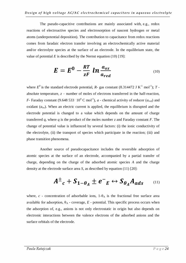
Figure 7 presents the most commonly used carbons as electrodes for EDLCs,
which include: activated carbons (ACs) [4, 21], carbon nanotubes (CNTs) [22], onion-
like carbons (OLCs) [23], graphene [24] and carbide-derived carbons (CDCs) [25].
Nonetheless, low cost and high specific capacitance are the essential criteria which
determine the choice of activated carbon as material for EDLCs.
D e s i g n o f h i g h v o l t a g e A C / A C e l e c t r o c h e m i c a l c a p a c i t o r s i n a q u e o u s e l e c t r o l y t e
Paula Ratajczak P a g e 26
Figure 7 Electron microscopy images of high surface area carbon materials: (a)
scanning electron microscopy (SEM) of AC particles [26]; (b) SEM of AC fabrics [27];
(c) SEM of AC fibers [27]; (d) SEM of vertically aligned CNT forest [28]; (e) SEM of
CNT fabric [28]; (f) SEM of randomly oriented CNTs within CNT paper mats [29]; (g)
transmission electron microscopy (TEM) of carbon onions [30]; (h) SEM of multilayer
graphene flakes [31]; (i) SEM of carbide derived carbons (CDC) [32].
Activated carbon
Activated carbon (AC) is a very complex and highly disordered material made
of nano-scale units. In the early model of non-graphitizable carbon proposed by
Franklin (Figure 8a) [33], the units constituted of few graphene layers [34] are oriented
randomly and connected with each other. The cross-links are sufficiently strong to
impede the movement of the layers to a more parallel arrangement. However, after the
model proposed by Stoeckli [35], it is believed that ACs sometimes involve single
fragments of graphene curved layers connected with each other, as presented in Figure
8b. It was found by high-resolution electron microscopy that high temperature treatment
of non-graphitizable carbon entails the production of faceted particles made of
misoriented stacks of parallel graphene layers [36].

D e s i g n o f h i g h v o l t a g e A C / A C e l e c t r o c h e m i c a l c a p a c i t o r s i n a q u e o u s e l e c t r o l y t e
Paula Ratajczak P a g e 27
Compared to some other forms of carbons (e.g., CNTs, OLCs), ACs are
characterized by a lower conductivity, which for supercapacitor electrodes is usually
compensated by using a percolator (carbon black or CNTs addition) and by appropriate
electrodes manufacturing process [37, 38, 39].
Figure 8 (a) 2D model of a non-graphitizable carbonaceous material [33]; (b) 3D model
of carbonaceous material [40].
Carbon nanotubes
Carbon nanotubes (CNTs) form a cylindrical 1D structure which contains either
one rolled-up graphene layer (single-wall CNT - SWCNT) or several ones (multiwalled
CNT - MWCNT) (Figure 9). Generally, they are produced either by catalyst assisted
chemical vapor deposition (CCVD) using a hydrocarbon feedstock, such as methane,
acetylene and propylene [41] or by CVD deposition in the nano-channels of an anodic
alumina template [42].
In contrast to ACs and CDCs, CNTs have relatively low SSA and low density,
which limit the volumetric capacitance and energy density of CNT-based EDLCs.
However, high electrical conductivity and open porosity of CNTs allow fast transport of
ions, and thus the system to reach high power.

D e s i g n o f h i g h v o l t a g e A C / A C e l e c t r o c h e m i c a l c a p a c i t o r s i n a q u e o u s e l e c t r o l y t e
Paula Ratajczak P a g e 28
Figure 9 (a) Structure of a single-wall carbon nanotube (SWCNT) and (b) multi-walled
carbon nanotube (MWCNT) [43].
Carbon onions
Carbon onions, also called carbon nano-onions (CNOs) or onion-like carbons
(OLCs) owe their name to the layered structure reminiscent to an onion, which contains
spherical closed carbon shells of fullerene or polyhedral nanostructure (Figure 10). They
offer a specific surface area up to 500-600 m2 g
-1 which is fully accessible to ions [30].
They are produced via several techniques, such as electron beam irradiation,
condensation of carbon vapor and vacuum precursor. Due to their 0D structure, small
diameter (<10 nm), high electrical conductivity, relatively easy dispersion as compared
to 1D nanotubes and 2D graphene, OLCs appear as a promising electrode material [44].
However, due to their high cost and low capacitance (about 30 F g-1
), they are more
preferably used as conductive agent to carbon based electrodes for high-power EDLCs.
Figure 10 3D structure of onion-like carbon (OLC) [45].
D e s i g n o f h i g h v o l t a g e A C / A C e l e c t r o c h e m i c a l c a p a c i t o r s i n a q u e o u s e l e c t r o l y t e
Paula Ratajczak P a g e 29
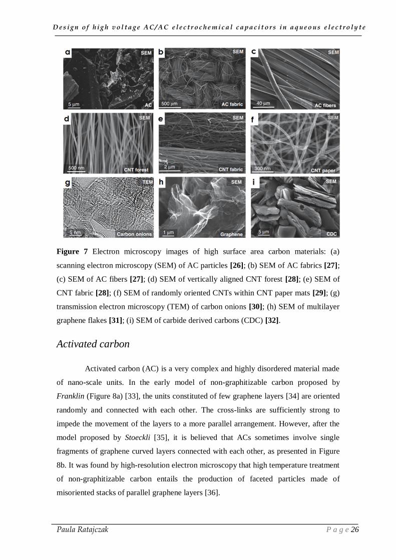
Carbide-derived carbons (CDCs)
Carbide-derived carbons (CDCs), also known as tunable nanoporous carbons,
are a class of highly porous carbon materials derived from binary (e.g. SiC, TiC) or
ternary carbides (e.g., Ti2AlC, Ti3SiC2), polymer-derived ceramics (e.g., Si-O-C or Ti-
C) or carbonitrides (Si-N-C) by selective etching of the metal atoms [46]. The most
commonly used preparation method of CDCs is a reactive extraction of the metal from
carbides with chlorine, where carbon grows from the outside to the core of particles
(Figure 11). To avoid sintering and aggregation of the material, generally, the synthesis
temperature does not exceed 1200 °C. In the last few years, CDCs attracted a lot of
attention as electrode materials for ECs and hydrogen storage applications, due to their
high specific surface area (up to 3100 m2 g
−1 for CDCs synthesized by electrospinning
of polycarbosilane with subsequent pyrolysis and chlorination) and broad range of pore
sizes (0.3 – 30 nm) [47]. Owing to the highly tunable porosity, SiC-CDC enables to
reach gravimetric capacitance of 75 F g-1
in 1.5 mol L-1
TEABF4/AN [48]. For the
further developments of this manuscript, structural/textural properties of CDCs and
activated carbons (ACs) will be considered as comparable.
Figure 11 Scheme of the carbide conversion to carbide-derived carbon (CDC)
depending on the reaction time [49].
Graphene
Graphene is a 2D structured carbon material with fully accessible surface area
(reaching in theory 2670 m2 g
-1) and high conductivity. However, due to the strong π-π
interactions, the graphene sheets tend to restack (Figure 12), which is a critical issue
entailing a decrease of accessible surface area and reduction of ions diffusion rates.
Therefore, techniques such as exfoliation and reduction of graphene oxide (GO), e.g.,

D e s i g n o f h i g h v o l t a g e A C / A C e l e c t r o c h e m i c a l c a p a c i t o r s i n a q u e o u s e l e c t r o l y t e
Paula Ratajczak P a g e 30
via microwave irradiation or heating of GO in propylene carbonate (PC), are applied to
increase the gravimetric capacitance of graphene-based electrodes (190 F g-1
in aqueous
and 120 F g-1
in organic electrolytes) [50]. Recently free-standing holey graphene
frameworks (HGF) with efficient ion transport pathways were reported [51]. The HGF
were prepared through hydrothermal reduction graphite oxide (GO) with simultaneous
low temperature etching of graphene, owing to the presence of H2O2 molecules. Due to
the formation of nanopores in the graphene sheets, this 3D self-assembled structure
enables to reach high and stable capacitance values (298 F g-1
) in 1-ethyl-3-
methylimidazolium tetra-fluoroborate/acetonitrile (EMIMBF4/AN) during 25,000
galvanostatic cycles with current density of 25 A g-1
.
Figure 12 Model of a layered microscopic segment of graphene sheets. [52]
2.2. Redox-active electrode materials
In the past decades, many redox-active materials have been studied to gain
additional charge from electrochemical reactions, such as conducting polymers [53] or
transition metal oxides (RuO2, MnO2, Fe3O4) [54, 55, 56]. However, due to the faradaic
charge storage mechanism, ECs with redox active electrodes do not exhibit long time
operation with a high efficiency.
Over the years, one of the most studied materials with pseudocapacitive
behavior has been conductive ruthenium oxide (RuO2) in acidic electrolytes. During the
transitions from the Ru+II
oxidation state to Ru+IV
, a fast and reversible electron transfer
with simultaneous electrosorption of protons on the surface of RuO2 particles takes
place, according to reaction (12) [14]:
)(22 OHRuOeHRuO
(12)
D e s i g n o f h i g h v o l t a g e A C / A C e l e c t r o c h e m i c a l c a p a c i t o r s i n a q u e o u s e l e c t r o l y t e
Paula Ratajczak P a g e 31
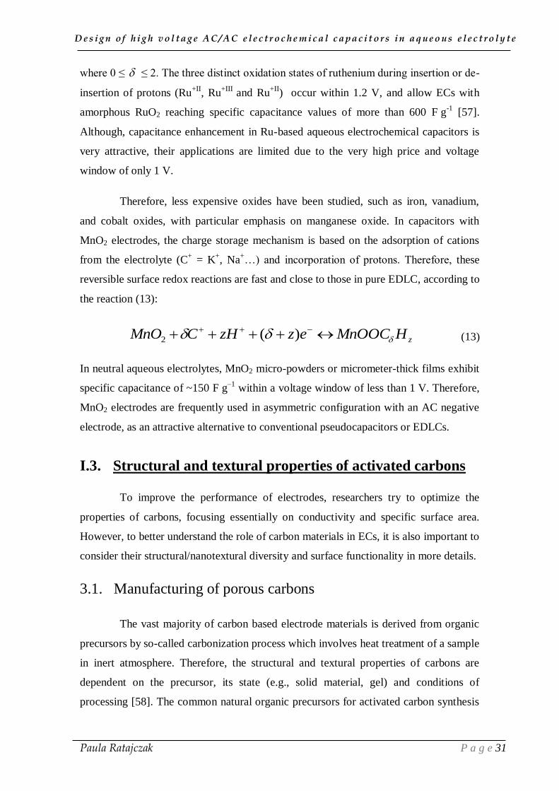
where 0 ≤ ≤ 2. The three distinct oxidation states of ruthenium during insertion or de-
insertion of protons (Ru+II
, Ru+III
and Ru+II
) occur within 1.2 V, and allow ECs with
amorphous RuO2 reaching specific capacitance values of more than 600 F g-1
[57].
Although, capacitance enhancement in Ru-based aqueous electrochemical capacitors is
very attractive, their applications are limited due to the very high price and voltage
window of only 1 V.
Therefore, less expensive oxides have been studied, such as iron, vanadium,
and cobalt oxides, with particular emphasis on manganese oxide. In capacitors with
MnO2 electrodes, the charge storage mechanism is based on the adsorption of cations
from the electrolyte (C+ = K
+, Na
+…) and incorporation of protons. Therefore, these
reversible surface redox reactions are fast and close to those in pure EDLC, according to
the reaction (13):
zHMnOOCezzHCMnO )(2 (13)
In neutral aqueous electrolytes, MnO2 micro-powders or micrometer-thick films exhibit
specific capacitance of ~150 F g–1
within a voltage window of less than 1 V. Therefore,
MnO2 electrodes are frequently used in asymmetric configuration with an AC negative
electrode, as an attractive alternative to conventional pseudocapacitors or EDLCs.
I.3. Structural and textural properties of activated carbons
To improve the performance of electrodes, researchers try to optimize the
properties of carbons, focusing essentially on conductivity and specific surface area.
However, to better understand the role of carbon materials in ECs, it is also important to
consider their structural/nanotextural diversity and surface functionality in more details.
3.1. Manufacturing of porous carbons
The vast majority of carbon based electrode materials is derived from organic
precursors by so-called carbonization process which involves heat treatment of a sample
in inert atmosphere. Therefore, the structural and textural properties of carbons are
dependent on the precursor, its state (e.g., solid material, gel) and conditions of
processing [58]. The common natural organic precursors for activated carbon synthesis

D e s i g n o f h i g h v o l t a g e A C / A C e l e c t r o c h e m i c a l c a p a c i t o r s i n a q u e o u s e l e c t r o l y t e
Paula Ratajczak P a g e 32
include: coal, peat, fruit stones, nut shells, wood, petroleum coke, pitch, lignite, starch,
sucrose, corn grain, leaves, coffee grounds, straw etc. [59, 60, 61, 62, 63, 64, 65, 66]. In
general, carbonized samples from natural organic precursors have a relatively low
porosity with a large number of interstices which block the pore entrances. Therefore,
the pre-carbonized product must be further physically or chemically activated in order
to open the porosity and to create new pores. The physical activation is conducted by
gasification of the pre-carbonized char at temperatures ranging from 700 to 1000 °C, in
the presence of an oxidizing agent (such as CO2, steam, air or mixture of these gases),
which increases the pore volume and surface area of the material by a controlled carbon
burn-off, according to equations (14) to (17) [67, 68]:
22 HCOOHC (14)
COCOC 22 (15)
22 COOC (16)
COOC 22 2 (17)
The production of ACs by chemical activation is carried out at slightly lower
temperatures (∼400–700 °C) and generally results in smaller pores and more uniform
pore size distribution [11]. The process involves the reaction of a precursor or a char
with a chemical reagent (such as KOH [69, 70], ZnCl2 [71, 72] or H3PO4 [73, 74]). As
reported, by activation with potassium hydroxide, it is possible to obtain ACs with
specific surface area above 2500 m2 g
−1 [75, 76]. Nonetheless, to remove residual
reactants as well as any inorganic residues (e.g., ash) which originate from the carbon
precursor or are introduced during preparation, post-activation washing is always
required.
Although it is generally believed that the activation process is required to open
the pores of carbonized precursors, carbons with well-developed porosity and good
capacitance values, as well as reproducible properties can be obtained by simple one-
step carbonization of synthetic polymers, e.g., through a rapid microwave heating of
polypyrrole (PPy) [77]. Recently, it has been also presented that self-activation proceeds
during carbonization of appropriate biomass precursors, e.g., tobacco [78] or seaweeds

D e s i g n o f h i g h v o l t a g e A C / A C e l e c t r o c h e m i c a l c a p a c i t o r s i n a q u e o u s e l e c t r o l y t e
Paula Ratajczak P a g e 33
[79, 80], where the second stage of chemical or physical activation is unnecessary. Due
to the presence of naturally embedded group I and II elements (such as potassium,
calcium, magnesium, sodium), during the thermal treatment, carbonization and self-
activation of the precursor occur simultaneously. For the Burley tobacco, the optimal
self-activation temperature is considered as 800 °C. At higher temperatures, annealing
of the materials dominates and provokes a decrease of specific surface area and average
pore size [78].
3.2. Surface functional groups on carbons
As presented in Figure 8b, carbon materials are constituted of fragments of
graphene layers connected with each other, each fragment containing edges and defect
like vacancies, leading to the development of surface functional groups [68]. As a result
of incomplete carbonization of the porous material, a part of the chemical structure is
associated with heteroatoms which are in the vast majority oxygen and hydrogen, and in
a lesser degree nitrogen and sulfur (Figure 13). Therefore, in addition to electrical
double-layer charging, faradic electron transfer reactions involving the surface
functional groups may be involved in energy storage [81, 82, 83]. In order to enhance
this contribution, the surface functionality of ACs is generally developed through: (i)
electrochemical polarization [84], (ii) chemical treatment [85], (iii) and plasma
treatment [86].
There are three types of surface oxides present on the carbon material, namely,
acidic, basic and neutral (Figure 13) [11]. Surface oxides with acidic nature are formed
when carbons are exposed to di-oxygen at 200-750 °C or by reactions with oxidizing
agents at room temperature. These surface groups include carboxylic, lactonic and
phenolic functionalities. The basic and neutral groups are formed after heat treatment of
AC to eliminate the surface functionalities, and further exposition of AC to di-oxygen at
low temperature. The basic oxygen-containing groups include ethers, carbonyls and
pyrone structures. Although, the acidic or basic nature of quinone/hydroquinone
functionalities is not strongly marked, their contribution to capacitance and creation of
catalytic active sites for, e.g., oxidative dehydrogenation reactions cannot be neglected
[87]. The contribution of quinone/hydroquinone pairs to capacitance can be observed in
cyclic voltammograms by cathodic and anodic waves at ~0 V vs Hg/Hg2SO4.
D e s i g n o f h i g h v o l t a g e A C / A C e l e c t r o c h e m i c a l c a p a c i t o r s i n a q u e o u s e l e c t r o l y t e
Paula Ratajczak P a g e 34
Nonetheless, the recent trend is to introduce the quinone/hydroquinone redox pair into
the electrolyte, which is simpler than, e.g., grafting of quinone derivatives on the surface
of carbon [88, 89].
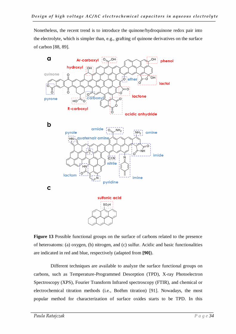
Figure 13 Possible functional groups on the surface of carbons related to the presence
of heteroatoms: (a) oxygen, (b) nitrogen, and (c) sulfur. Acidic and basic functionalities
are indicated in red and blue, respectively (adapted from [90]).
Different techniques are available to analyze the surface functional groups on
carbons, such as Temperature-Programmed Desorption (TPD), X-ray Photoelectron
Spectroscopy (XPS), Fourier Transform Infrared spectroscopy (FTIR), and chemical or
electrochemical titration methods (i.e., Boëhm titration) [91]. Nowadays, the most
popular method for characterization of surface oxides starts to be TPD. In this

D e s i g n o f h i g h v o l t a g e A C / A C e l e c t r o c h e m i c a l c a p a c i t o r s i n a q u e o u s e l e c t r o l y t e
Paula Ratajczak P a g e 35
technique, the functionalities present on the carbon surface are thermally decomposed
releasing primarily CO2, CO and/or H2O at different temperatures [92]. The nature of
the groups is evaluated from the type of released gas and the decomposition temperature
[93]. The TPD patterns of CO and CO2 evolution are a sum of peaks, therefore, to
estimate the amount of each type of oxygenated surface group, the spectra can be
deconvoluted by using, e.g. a multiple Gaussian function (Figure 14) [92].
Figure 14 Deconvolution of TPD patterns for a carbon sample oxidized with 5 mol L-1
nitric acid for 6 hours at boiling temperature: (a) CO2 pattern; (b) CO pattern; TPD
experimental data /; individual peaks ---; sum of the individual peaks -) (adapted from
[92]).
Apart from the capacitive contribution, the presence of functional groups on
the surface of AC influence the double-layer properties of carbon, such as wettability,
rest potential, ESR, leakage current and self-discharge characteristics [3, 11]. As the
amount of oxygen associated with the carbon surface increases, the hydrophilicity of
carbon increases. Therefore, ACs with high oxygen content can be easier wetted by
water than pure carbons without oxygenated surface functionalities.
3.3. Effect of porous texture of activated carbons on the
capacitive performance
The nature of the organic precursor and the conditions of AC synthesis, such as
carbonization/activation temperatures and kind of used activating agent, influence the
pore size distribution of carbon materials. Due to the complex interconnected network
of internal pores, the BET specific surface area of AC ranges between 500-3000 m2 g
-1.

D e s i g n o f h i g h v o l t a g e A C / A C e l e c t r o c h e m i c a l c a p a c i t o r s i n a q u e o u s e l e c t r o l y t e
Paula Ratajczak P a g e 36
The parameters closely connected with the specific surface area (pore volume of
carbons, size and shape of pores, tortuosity) also play an important role in charge
storage. According to the IUPAC classification, there are three main kinds of pores: (i)
micropores (with diameters <2 nm), mesopores (diameters from 2 to 50 nm) and
macropores (diameters >50 nm) [94]. Since the macropores do not take part in the
actual adsorption processes, their contribution to the total surface area is negligible. Ions
are the most efficiently adsorbed in the micropores providing the high surface area,
while the mesopores are intended to allow the ions to be transported to the micropores
[95, 96, 97]. To enhance capacitance and to lower the ESR values, it is important to
keep an appropriate volume ratio of meso/micropores, while selecting carbons for
EDLCs [98, 99]. For AC/AC electrochemical capacitors in sulfuric acid, the optimum
mesopore volume ratio is in the range of 20 to 50% [100]. The role of micropores is
seen during slow charging (2 mVs−1
scan rate), whilst the beneficial effect of
mesoporous transportation channels on capacitance is pronounced at higher rates [100].
The adsorption of a gaseous medium at a fixed temperature (generally nitrogen
at -192°C) is the most common method used to investigate the porosity of carbons. The
characteristics of activated carbons are estimated by commercial sorption equipment,
generally using in-built software based on the adsorption isotherm of a given
adsorbate/adsorbent system and a model of the adsorption process [101, 102, 103].
Nevertheless, in highly porous materials, the adsorption may occur via a pore filling
mechanism, rather than by surface coverage only (as it is assumed by the Langmuir and
Brunauer–Emmett–Teller theory (BET) [104]). Therefore, in the narrow pores, the
application of the BET equation can lead to unrealistic surface-area (SBET) estimations
[105, 106]. More and more often, the regularized density functional theory (DFT) is
taken into consideration as a more accurate way to correlate capacitance with SSA. In
the model, slit-shaped pore geometry is assumed, and it concerns the adsorption and
capillary condensation in pores of different geometry and surface chemistry [107].
Figure 15a shows that the gravimetric capacitance of ACs and carbon blacks
increases almost linearly with SSA up to SBET ≈ 1500 m2 g
-1, and then for carbons with
higher activation degree a plateau is visible [108]. For the same carbons, the
proportionality region of capacitance with SDFT is more extended than when using SBET,
but still for SDFT higher than 1200 m2 g
-1 a capacitance saturation phenomenon can be
observed (Figure 15b). For carbons materials with SDFT around 1200 m2 g
-1, due to the

D e s i g n o f h i g h v o l t a g e A C / A C e l e c t r o c h e m i c a l c a p a c i t o r s i n a q u e o u s e l e c t r o l y t e
Paula Ratajczak P a g e 37
increase in pore volume, the carbon pore walls become too thin to accommodate
additional charges, which results in capacitance saturation [108].
Figure 15 Gravimetric capacitance vs (a) BET specific surface area; (b) DFT specific
surface area (adapted from [108]).
To overcome the over- or under-estimation of SSA derived from the BET
equation, it is more accurate to combine gas adsorption and immersion calorimetry for
porous carbons of different origins, as proposed by Stoeckli et al [109, 110]. Contrary to
the anomalous increase of C/SBET (F m-2
) for TiC-based carbons in pores of less than 1
nm when using TEABF4 in AN electrolyte [111], the C/Sav values are constant in pores
between 0.7 and 1.8 nm [112, 113]. Furthermore, in this pore size range, the volumetric
capacitance (C/Wo) increases with decreasing pore width (Figure 16). Interestingly, the
linearization of volumetric capacitance vs L0 led to similar trend in 1 mol L-1
TEABF4
in AN and 6 mol L-1
KOH electrolyte for two series of activated carbons, while
assuming slit-shaped pores [114].
According to equation (4), capacitance might be also overestimated when Lo
decreases, if assuming constant electrolyte dielectric permittivity εr. In fact, since slit-
shape micropores contain a constant amount of ions which are surrounded by a variable
amount of solvent molecules, the relative electrolyte permittivity in micropores
decreases with the solvent to ion ratio, i.e. with the decrease of L0. Therefore, the Feng
model [115] which suggests a gradual decrease of relative permittivity of TEABF4/AN,
explains the almost constant value of C/S in pores below 1 nm. However, the studies on
microporous carbons cannot longer rely on models, which still assume that solvated

D e s i g n o f h i g h v o l t a g e A C / A C e l e c t r o c h e m i c a l c a p a c i t o r s i n a q u e o u s e l e c t r o l y t e
Paula Ratajczak P a g e 38
ions occupy a central position in micropores, which in turn feature in well-defined shape
and rigidity, and are not interconnected.
Figure 16 Volumetric capacitance of various microporous carbons in TEABF4/AN
electrolyte vs average pore width (Lo) accessible to CCl4; Wo represents the volume of
micropores deduced from the carbon tetrachloride (CCl4) isotherm, assuming that the
diameters of TEA+ (0.68 nm) and CCl4 (0.63 nm) are comparable [113].
From the foregoing, and considering the diameter of solvated TEA+ (1.3 nm)
and BF4- (1.16 nm) and desolvated TEA
+ (0.67 nm) and BF4
- (0.48 nm) [116], it
suggests that ions need to be at least partly desolvated to penetrate into the micropores
[117]. Desolvation of TEA+ and BF4
- was confirmed by nuclear magnetic resonance
(NMR) on AC electrodes extracted from capacitors charged up to different voltage
values in the TEABF4/AN electrolyte. Figure 17 shows the molar proportions of TEA+
and BF4- and the relative amount of AN vs the total amount of electrolyte species after
polarization at various voltages [118]. Predictably, due to charging, large TEA+
cations
in the positive electrode are replaced by smaller BF4-
anions, leaving the place for
solvent molecules, which amount remains nearly constant up to 4.0 V. Simultaneously,
in the negative electrode, small anions are replaced by larger cations, and consequently
the AN concentration decreases rapidly and becomes negligible at 2.7 V (no AN
molecules are left in the micropores of the AC-based electrode). The AN solvent is
expelled by incoming TEA+
and is further stored in the mesopores.

D e s i g n o f h i g h v o l t a g e A C / A C e l e c t r o c h e m i c a l c a p a c i t o r s i n a q u e o u s e l e c t r o l y t e
Paula Ratajczak P a g e 39
Figure 17 Molar proportions of TEA+ and BF4
- in the positive and negative electrodes
of an AC/AC electrochemical capacitor calculated from NMR spectra, and relative
amount of AN versus the total amount of electrolyte species, after polarization at
various cell potentials for 30 min (adapted from [118]).
I.4. Electrolytes for electrochemical capacitors
In order to extend the range of ECs applications, the current researches seek for
strategies which improve their energy density. According to equation (6), the value of
stored energy can be enhanced either by increasing the capacitance C or by extending
the operating voltage U. Since the latter is closely determined by the stability window of
the applied electrolyte, this paragraph is focused on pros and cons of electrolytes which
are designed and customized for different ECs applications. Beside the electrochemical
stability window, which is a key factor affecting the electrolyte selection, the physical
properties of the electrolytic solution, such as, mobility and molar conductivity of ions,
are found to be also important in terms of energy storage efficiency. It is commonly
known that the charge storage capacitance and resistance of the electrode material are
affected by the nature of the electrolyte, i.e. the ionic radii of unsolvated and solvated
ions, the molar conductivity of ions and their mobility in the pores of electrodes [119].
Calvo et al. showed that it is possible to predict the capacitance for each electrolyte
based on the information about molar conductivity of ions and surface functionality of
the electrode material [120].

D e s i g n o f h i g h v o l t a g e A C / A C e l e c t r o c h e m i c a l c a p a c i t o r s i n a q u e o u s e l e c t r o l y t e
Paula Ratajczak P a g e 40
The most commonly used electrolytes for ECs are aqueous media (sulfuric acid
and potassium hydroxide), organic electrolytes and ionic liquids (ILs) [121]. According
to formula (4), the capacitance values of ECs with carbon electrodes of same SSA are
significantly higher in aqueous electrolytes than in non-aqueous solutions, due to high
dielectric constant of the aqueous media [122, 123]. The aqueous electrolytes display
values of ionic conductivity up to ∼1 S cm−1
for 30% H2SO4 [11], while for the
commonly used organic electrolytes (e.g., TEABF4 in propylene carbonate) it is only
∼0.02 S cm-1
[124], and ~0.01 S cm-1
for typical room temperature ionic liquids
(RTILs) [125]. The electrolytic solution should be also thermally stable, have low
viscosity, low toxicity and low cost [126]. But yet, none of the available electrolytes
fully meet all the mentioned desires.
4.1. Aqueous electrolytes
On the point of view of production, the main motive for the choice of aqueous
electrolyte is the low cost. While implementing non-aqueous media, all components
(carbon material, separator, electrolyte itself) need to be well-dried in order to ensure a
long cycle-life of the system, whereas drying is not required in case of aqueous
electrolytes, which dramatically decreases the production cost of the final device.
Moreover, water-based solvents provide strong solvation and tendency for complete
dissociation or minimum ion pairing, feature in large dipolar moments (through
hydrogen bonded structures) and high dielectric constants, leading to lower ESR values
than organic solvents [83].
When comparing the most commonly used aqueous electrolytes (sulfuric acid,
potassium hydroxide) in electrochemical power sources, the highest capacitance values
and best electrochemical performance are achieved with H2SO4 due to its greater ionic
conductivity, faster mobility of H+ than K
+ and greater activity of the basic oxygenated
groups on the surface of the electrode material.
Unfortunately, a major disadvantage of water-based electrolytes, when
considering formulae (6) and (7), is their low thermodynamic stability and consequently
the low reachable voltage of 1.23 V [120]. Practically, in symmetric AC/AC
electrochemical capacitors with H2SO4 and KOH aqueous electrolytes it is even less
than 1 V [127, 128, 129, 130, 131], whereas 2.7 V-2.8 V can be reached with ECs in

D e s i g n o f h i g h v o l t a g e A C / A C e l e c t r o c h e m i c a l c a p a c i t o r s i n a q u e o u s e l e c t r o l y t e
Paula Ratajczak P a g e 41
organic medium [132]. Therefore, researchers still seek for media which assure high
energy storage by extended operating voltage range, while lowering the costs of the
EC’s assembling process and enabling to apply various current collectors due to less
corrosive properties than, i.e., sulfuric acid.
Promising neutral salt aqueous electrolytes
Lately, voltage values as high as 1.6 V were found for AC/AC electrochemical
capacitors in 0.5 mol L−1
Na2SO4 [131, 79] and even 2 V when using 1 mol L−1
Li2SO4
[133]. As presented on the Ragone plots of AC/AC electrochemical capacitors in
Li2SO4 and KOH aqueous electrolytes (Figure 18), the energy density in Li2SO4 is
enhanced by 80% as compared with KOH [128]. The energy and power density reached
at the time constant of 25 s are 12.3 Wh kg−1
and 1.6 kW g−1
in Li2SO4 against 7.2 Wh
kg−1
and 1.0 kW g−1
in KOH, respectively. Furthermore, due to much less corrosive
properties than sulfuric acid, and possibility to extend the operating voltage by
appropriate combination of electrode materials, these neutral electrolytes are by far
much preferable for further scaling-up to an industrial production [130, 134, 135].
Figure 18 Ragone plots of AC/AC capacitors in 1 mol L-1
Li2SO4 and 6 mol L-1
KOH
aqueous solutions with cell operating potential windows 0−1.6 V and 0−1.0 V,
respectively. Values calculated for the total mass of active materials [128].

D e s i g n o f h i g h v o l t a g e A C / A C e l e c t r o c h e m i c a l c a p a c i t o r s i n a q u e o u s e l e c t r o l y t e
Paula Ratajczak P a g e 42
The different performance of AC in neutral, acidic and basic electrolytes is
presented by the three-electrode cyclic voltammograms in Figure 19. The potential
window in Na2SO4 is roughly twice larger than in the traditional KOH and H2SO4
electrolytes [127, 128, 129, 131]. Such enhancement of the operating potential window
has been attributed either to the strong solvation of cations and anions [133] or to the
high over-potential for di-hydrogen evolution at the negative electrode [136]. SO42-
is
one of the biggest and strongest solvated inorganic anions, having up to 40 water
molecules in the solvation shell, with desolvation energy of about 108 kJ mol-1
per one
bond between SO42-
and water [133].
Figure 19 Potential stability window of activated carbon in 6 mol L-1
KOH, 1 mol L-1
H2SO4 and 0.5 mol L-1
Na2SO4 determined by three-electrode cyclic voltammograms
(2 mV s-1
) [131].
Due to the full reversibility of the chemisorption process, hydrogen storage is
an interesting option enabling a potential faradaic contribution in addition to the EDL
capacitance and extension of the electrochemical stability window. Since ACs are
characterized by highly developed porosity and easily tunable ultramicroporosity, they

D e s i g n o f h i g h v o l t a g e A C / A C e l e c t r o c h e m i c a l c a p a c i t o r s i n a q u e o u s e l e c t r o l y t e
Paula Ratajczak P a g e 43
appear as the most interesting materials for this purpose. Activated carbons can store up
to 2 wt% of hydrogen formed by electrochemical reduction of water under ambient
pressure and temperature conditions [137, 138, 139, 140, 141].
Under negative polarization, the electrons are supplied to carbon and,
depending on pH, they lead to the formation of nascent hydrogen, accordingly to
equations (18) or (19) [142]:
in acidic solution: H3O+ + e
- → H + H2O (18)
in alkaline solution: H2O + e- → H + OH
- (19)
then, the in statu nascendi hydrogen is rapidly chemisorbed onto the carbon surface
[143, 144]:
C + H → CHad (20)
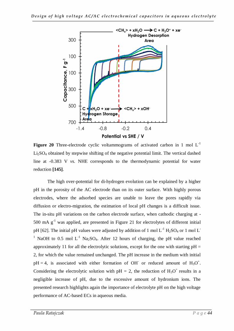
The increase of negative current below -0.8 V vs NHE, in case of 1 mol L-1
Li2SO4,
indicates the plausible limit for negative polarization beyond which evolution of
gaseous di-hydrogen takes place (as observed by the oscillations due to bubbling on the
CVs (Figure 20)), according to equation (21):
2H → H2 (21)
Di-hydrogen is also partly formed from the chemisorbed hydrogen, accordingly to
equations (22) and (23) [142]:
CHad + H2O + e- → H2 + OH- + C (22)
CHad + CHad → H2 + 2C (23)
The reversible hydrogen chemisorption is further evidenced in the cyclic
voltammograms (Figure 20) by an anodic desorption peak at around 0.4 V vs NHE
[136].
D e s i g n o f h i g h v o l t a g e A C / A C e l e c t r o c h e m i c a l c a p a c i t o r s i n a q u e o u s e l e c t r o l y t e
Paula Ratajczak P a g e 44
Figure 20 Three-electrode cyclic voltammograms of activated carbon in 1 mol L-1
Li2SO4 obtained by stepwise shifting of the negative potential limit. The vertical dashed
line at -0.383 V vs. NHE corresponds to the thermodynamic potential for water
reduction [145].
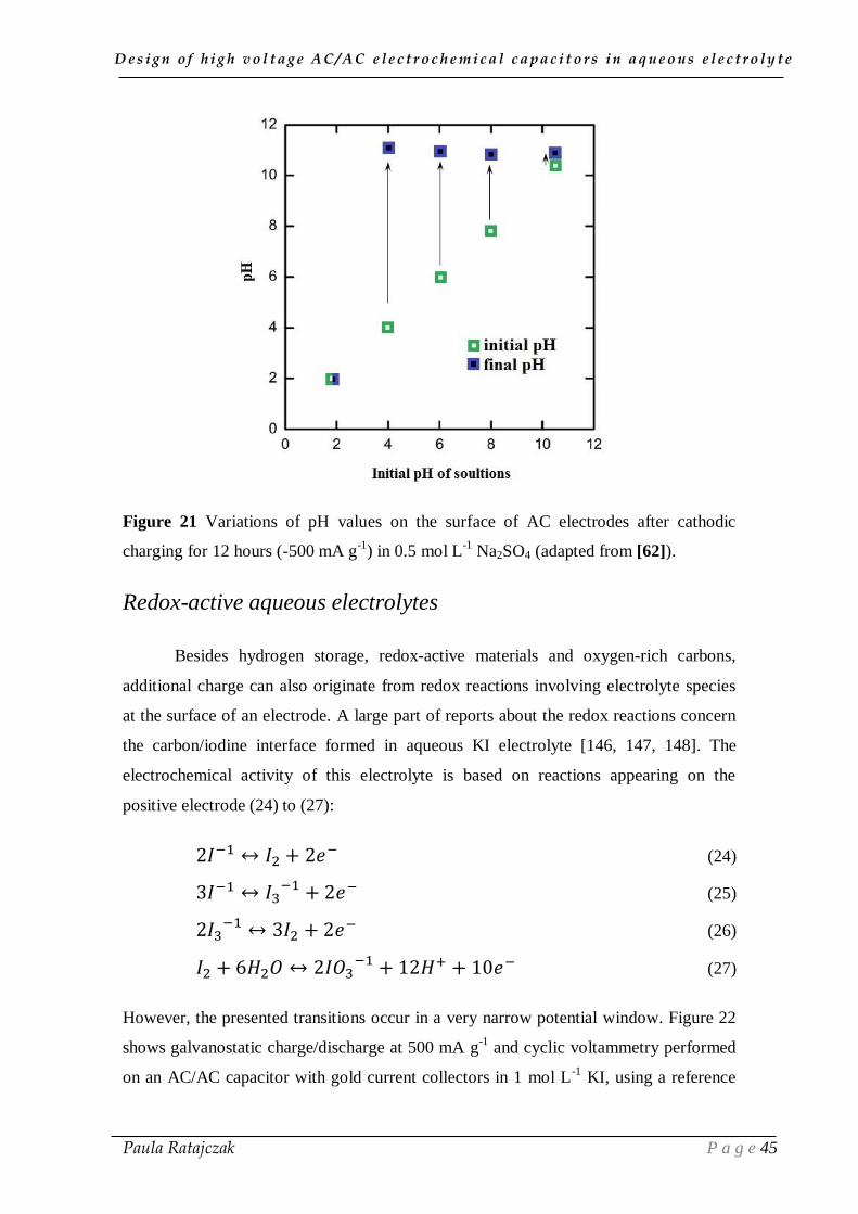
The high over-potential for di-hydrogen evolution can be explained by a higher
pH in the porosity of the AC electrode than on its outer surface. With highly porous
electrodes, where the adsorbed species are unable to leave the pores rapidly via
diffusion or electro-migration, the estimation of local pH changes is a difficult issue.
The in-situ pH variations on the carbon electrode surface, when cathodic charging at -
500 mA g-1
was applied, are presented in Figure 21 for electrolytes of different initial
pH [62]. The initial pH values were adjusted by addition of 1 mol L-1
H2SO4 or 1 mol L-
1 NaOH to 0.5 mol L
-1 Na2SO4. After 12 hours of charging, the pH value reached
approximately 11 for all the electrolytic solutions, except for the one with starting pH =
2, for which the value remained unchanged. The pH increase in the medium with initial
pH = 4, is associated with either formation of OH- or reduced amount of H3O
+.
Considering the electrolytic solution with pH = 2, the reduction of H3O+
results in a
negligible increase of pH, due to the excessive amount of hydronium ions. The
presented research highlights again the importance of electrolyte pH on the high voltage
performance of AC-based ECs in aqueous media.
D e s i g n o f h i g h v o l t a g e A C / A C e l e c t r o c h e m i c a l c a p a c i t o r s i n a q u e o u s e l e c t r o l y t e
Paula Ratajczak P a g e 45
Figure 21 Variations of pH values on the surface of AC electrodes after cathodic
charging for 12 hours (-500 mA g-1
) in 0.5 mol L-1
Na2SO4 (adapted from [62]).
Redox-active aqueous electrolytes
Besides hydrogen storage, redox-active materials and oxygen-rich carbons,
additional charge can also originate from redox reactions involving electrolyte species
at the surface of an electrode. A large part of reports about the redox reactions concern
the carbon/iodine interface formed in aqueous KI electrolyte [146, 147, 148]. The
electrochemical activity of this electrolyte is based on reactions appearing on the
positive electrode (24) to (27):
2𝐼−1 ↔ 𝐼2 + 2𝑒− (24)
3𝐼−1 ↔ 𝐼3−1 + 2𝑒− (25)
2𝐼3−1 ↔ 3𝐼2 + 2𝑒− (26)
𝐼2 + 6𝐻2𝑂 ↔ 2𝐼𝑂3−1 + 12𝐻+ + 10𝑒− (27)
However, the presented transitions occur in a very narrow potential window. Figure 22
shows galvanostatic charge/discharge at 500 mA g-1
and cyclic voltammetry performed
on an AC/AC capacitor with gold current collectors in 1 mol L-1
KI, using a reference

D e s i g n o f h i g h v o l t a g e A C / A C e l e c t r o c h e m i c a l c a p a c i t o r s i n a q u e o u s e l e c t r o l y t e
Paula Ratajczak P a g e 46
electrode to monitor the behavior of individual electrodes. Reversible redox peaks are
observed at the positive electrode (Figure 22b) between 0 to 0.14 V vs Hg/Hg2Cl2,
whereas the negative electrode has an EDL behavior with a typical rectangular shape of
CV [146]. Due to the series dependence of the electrochemical circuit, the gravimetric
capacitance of the cell (260 F g-1
) is limited by the electrode with the smallest
capacitance, i.e. the negative electrode [146]. The AC/AC cell with this electrolyte and
gold collectors has a good cycle life with more than 80% of the initial capacitance value
after 10,000 galvanostatic cycles at a current density of 1 A g-1
. It is worth to mention
that iodide salts allow using cheap stainless steel current collectors, which broadens the
possibilities of their applications as electrolytes for ECs. After 15,000 charge/discharge
cycles at 2 A g-1
as well as after 150 hours of floating at 1.2 V on AC/AC cell in 2 mol
L-1
NaI, no traces of corrosion of stainless steel collectors were observed [148].
Figure 22 (a) Two-electrode AC/AC cell in 1 mol L-1
KI solution with SCE reference
electrode: galvanostatic charge/discharge (500 mA g-1
); (b) cyclic voltammograms (5
mV s-1
) of the electrodes and of the cell [146].
As previously mentioned, the capacitance of the AC/AC capacitor is limited by
the low capacitance of the EDL electrode (see equation (5)). Therefore, to enhance the
capacitance of the negative electrode, an AC/AC capacitor using 1 mol L-1
KI as anolyte
and 1 mol L-1
VOSO4 as catholyte, and a Nafion membrane as separator has been
developed [149]. With the selected redox-active electrolytes, the galvanostatic (0.5 A g-
1) discharge capacitance of the system reaches 500 F g
-1. The capacitance of the
negative electrode is enhanced by multi-electron reactions as in equations (28) to (32):
𝑉𝑂𝐻2+ + 𝐻+ + 𝑒− ↔ 𝑉2+ + 𝐻2𝑂 (28)
[𝐻2𝑉10𝑂28]4− + 54𝐻+ + 30𝑒− ↔ 10𝑉2+ + 28𝐻2𝑂 (29)

D e s i g n o f h i g h v o l t a g e A C / A C e l e c t r o c h e m i c a l c a p a c i t o r s i n a q u e o u s e l e c t r o l y t e
Paula Ratajczak P a g e 47
[𝐻2𝑉10𝑂28]4− + 44𝐻+ + 20𝑒− ↔ 10𝑉𝑂𝐻2+ + 18𝐻2𝑂 (30)
𝐻𝑉2𝑂73− + 9𝐻+ + 6𝑒− ↔ 2𝑉𝑂 + 5𝐻2𝑂 (31)
𝐻𝑉2𝑂73− + 13𝐻+ + 10𝑒− ↔ 2𝑉 + 7𝐻2𝑂 (32)
Similarly, hydroquinone has been added to 1 mol L-1
H2SO4 electrolyte,
transforming a symmetric AC/AC electrochemical capacitor into a hybrid redox system
[150, 151]. The development of the quinone/hydroquinone redox reaction on the carbon
surface (Figure 23) [152] led the positive electrode to behave as a battery one, whereas
the negative electrode remains of the EDL type.
Figure 23 Redox reaction of the quinone/hydroquinone redox pair.
However, the battery-like behavior of the positive electrode limits the long-term
stability of the cell in HQ/H2SO4 electrolyte, which demonstrates a decrease in
capacitance to 65% of its initial value after 4,000 cycles up to 1 V at current density of
4.4 mA cm-2
. The initial capacitance decay after 1,000 cycles is probably attributed to
the non-completed quinone/hydroquinone redox reactions within the voltage window
from 0 V to 1 V [151]. Although the hybrid systems demonstrate potentialities for
gaining in capacitance, such cells operate almost always at the expense of the cycle-life.
Besides naturally occurring surface functionalities, active molecules can be
chemically/electrochemically grafted onto the carbon surface to enhance the capacitance
of AC/AC ECs in aqueous media through faradaic contribution. Grafting of quinone
derivatives is usually performed by electrochemical or chemical reduction of diazonium
cations [153, 154, 155]. Since, the possible redox mechanisms involve proton and
electron transfers, the pH of the applied electrolyte has a significant influence on the
capacitance properties of quinone-modified carbons. The attachment of anthraquinone

D e s i g n o f h i g h v o l t a g e A C / A C e l e c t r o c h e m i c a l c a p a c i t o r s i n a q u e o u s e l e c t r o l y t e
Paula Ratajczak P a g e 48
groups to the surface of mesoporous carbon black (BP2000) enhances the capacitance
from 100 F g-1
for the unmodified carbon to 195 F g-1
for the grafted carbon in 0.1 mol
L-1
H2SO4 [88] However, the highly corrosive character of H2SO4 would impose to use,
e.g., neutral electrolytes, especially in the presence of stainless steel current collectors.
4.2. Organic electrolytes
Most of the industrial EDLCs available in the market are based on organic
electrolytes, due to their high thermodynamic stability window. However, the practical
operating voltage of organic media in symmetric AC/AC electrochemical capacitors
depends strongly on the impurities of the components, such as water and functional
groups on the surface of carbons [156, 157].
The most commonly used organic salt is tetraethylammonium tetrafluoroborate
(TEABF4), due to its moderately good conductivity and good solubility in non-aqueous
solvents. Currently, the most widely used solvent is acetonitrile (AN); however,
propylene carbonate (PC) has also many adherents, especially in Japan. It was reported
that PC exhibits a slightly stronger polarity, a higher density, viscosity and dielectric
constant than AN [158]. However, solutions in AN exhibit lower electric resistance, and
the increase of power density is accompanied by nearly constant energy density values
[159]. The electrolytes based on AN are usually characterized by about four times
higher conductivity than the PC-based ones [160]. Regarding the safety issues, AN has
very low flash point (5 °C) and emits toxic combustion products [161, 162]. Therefore,
researchers have used different types of solvents for organic electrolytes, such as
sulfone, dimethylsulfone, and ethyl methyl carbonate [163]. Moreover, it has been
found recently, that nitrile- and dinitrile-based electrolytes, e.g., adiponitrile (ADN) and
sebaconitrile, due to their high electrochemical stability, are appropriate for i.e., high-
voltage Li-ion batteries [164, 165]. Therefore, ADN started to be also used for EDLCs
[166], and it was revealed that an EDLC in 0.7 mol L-1
TEABF4/ADN is stable up to
3.5-3.6 V with capacitance loss of less than 20% after 50,000 cycles [167]. Adiponitrile
has a very low vapor pressure and a moderated viscosity; however, poor solubility of
TEABF4 in ADN (the maximum concentration of TEABF4 in ADN at 25 °C is 0.8
mol L-1
) limits the physical properties of ADN-based electrolytes [157]. For instance, it
affects their ionic conductivity, which is about 11 times smaller than that of AN-based
electrolytes [166]. Figure 24 shows that an EDLC in TEABF4/ADN does not
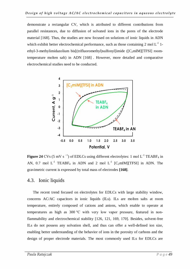
D e s i g n o f h i g h v o l t a g e A C / A C e l e c t r o c h e m i c a l c a p a c i t o r s i n a q u e o u s e l e c t r o l y t e
Paula Ratajczak P a g e 49
demonstrate a rectangular CV, which is attributed to different contributions from
parallel resistances, due to diffusion of solvated ions in the pores of the electrode
material [168]. Thus, the studies are now focused on solutions of ionic liquids in ADN
which exhibit better electrochemical performance, such as those containing 2 mol L-1
1-
ethyl-3-methylimidazolium bis[(trifluoromethyl)sulfonyl]imide ([C2mIM][TFSI] room-
temperature molten salt) in ADN [168] . However, more detailed and comparative
electrochemical studies need to be conducted.
Figure 24 CVs (5 mV s −1
) of EDLCs using different electrolytes: 1 mol L-1
TEABF4 in
AN, 0.7 mol L-1
TEABF4 in ADN and 2 mol L-1
[C2mIM][TFSI] in ADN. The
gravimetric current is expressed by total mass of electrodes [168].
4.3. Ionic liquids
The recent trend focused on electrolytes for EDLCs with large stability window,
concerns AC/AC capacitors in ionic liquids (ILs). ILs are molten salts at room
temperature, entirely composed of cations and anions, which enable to operate at
temperatures as high as 300 °C with very low vapor pressure, featured in non-
flammability and electrochemical stability [126, 121, 169, 170]. Besides, solvent-free
ILs do not possess any solvation shell, and thus can offer a well-defined ion size,
enabling better understanding of the behavior of ions in the porosity of carbons and the
design of proper electrode materials. The most commonly used ILs for EDLCs are

D e s i g n o f h i g h v o l t a g e A C / A C e l e c t r o c h e m i c a l c a p a c i t o r s i n a q u e o u s e l e c t r o l y t e
Paula Ratajczak P a g e 50
imidazolium, pyrrolidinium, and ammonium salts with anions such as tetrafluoroborate,
trifluoromethanesulfonate, bis(trifluoromethanesulfonyl)imide, bis(fluorosulfonyl)imide
and hexafluorophosphate [126]. Galvanostatic cycling of an AC/AC electrochemical
capacitor in N-methyl-N-butyl-pyrrolidinium bis(trifluoromethylsulfonyl) imide
(PYR14TFSI) demonstrated 95% efficiency at 3.5 V and 60°C after 65,000 cycles [169].
A constant voltage hold (floating) at 3.4 V revealed a long time operation (500 hours) of
EDLCs based on 1-ethyl-3-methylimidazolium tetrafluoroborate ([EMIM]BF4) with
mesoporous carbon black (BP 2000) [171].
Since high viscosity, and thus high resistance and low conductivity at room
temperature (typically ~14 mS cm-1
[172]) influence the efficiency of the charging and
discharging processes, the conductivity of EDLC with ILs phosphonium salts could be
improved by adding 25 wt% of acetonitrile (Figure 25) [173]. For capacitors with the
same mass of KOH activated carbon in the electrodes, the operating voltage is
significantly increased to 3.4 V in the case of the ILs/AN 25% electrolyte in comparison
with the conventional organic one (TEABF4/AN) and the aqueous acidic solution (1 mol
L-1
H2SO4). The irregular shape of CV which is determined by different size of cation
and anion of IL, suggests a need of suitable matching of pores size of positive and
negative AC electrode with the ions size of the ILs.
Figure 25 Cyclic voltammograms (5mV s-1
) for AC-based ECs in IL phosphonium salt
/AN 25%, organic and acidic electrolytic solutions [173].

D e s i g n o f h i g h v o l t a g e A C / A C e l e c t r o c h e m i c a l c a p a c i t o r s i n a q u e o u s e l e c t r o l y t e
Paula Ratajczak P a g e 51
Notwithstanding, despite the wide voltage window of ILs, low conductivity at room
temperature, high price and complex purification processes restrict further scaling-up.
Therefore, recently, the Azepane compound, which is a cheap by-product of polyamide
industry, was used for the synthesis of Azp14TFSI and Azp16TFSI [174]. However, the
large cation size of this electrolyte results in greater viscosity and lower conductivity as
compared to, e.g., Pyr14TFSI. A further study on potentialities of this new class of
electrolytes for EDLCs is still required [175].
I.5. Conclusion
In this chapter, the state-of-the-art on electrochemical capacitors (ECs) has been
presented. The charge storage mechanism of electrical double-layer capacitors EDLCs
is based on electrostatic interactions between electrolyte ions and the charged surface of
carbon electrodes. Since the pure charging of the electrical double-layer does not
involve any electron exchange, the power in EDLCs is much higher than in lithium
batteries; however, in turn, the energy density is lower than in batteries. Therefore, most
research efforts are focused on the energy density enhancement. It can be done by
controlling voltage and capacitance.
The voltage range is essentially limited by the electrochemical stability of the
electrolyte. Organic electrolytes allow high potential window – around 2.7 – 2.8 V to be
reached, against around 1 V for conventional aqueous electrolytes applied in battery
systems (sulfuric acid and potassium hydroxide). Hence, organic solutions are preferred
in many industrial capacitors, despite their high cost, environment unfriendliness and
low conductivity, while compared to aqueous media. A lot of attention is recently paid
to ionic liquids, however, considering economical, safety and ecological aspects,
aqueous electrolytes exhibit numerous advantages, and excel in high power densities as
well. Furthermore, while considering the operating voltage window of ECs based on
aqueous electrolytes, neutral aqueous sulfates, due to high over-potential of hydrogen
evolution and strong solvation of ions, offer to reach 1.6 V in Na2SO4 and even 2 V in
Li2SO4.
Since all the previous works with promising neutral sulfate electrolytes were
conducted with expensive gold collectors, this thesis research will be focused on design
and development of an environmentally friendly AC/AC electrochemical capacitor
D e s i g n o f h i g h v o l t a g e A C / A C e l e c t r o c h e m i c a l c a p a c i t o r s i n a q u e o u s e l e c t r o l y t e
Paula Ratajczak P a g e 52
using 1 mol L-1
Li2SO4, with cheap stainless steel current collectors. Furthermore, the
analysis on possible perturbation phenomena which occur during long-term operation of
ECs has been never conducted in the domain of high voltage AC/AC capacitors using
aqueous electrolytes. Therefore, the actual effect of operating voltage on the state-of-
health (SOH) of the device under accelerated ageing needs to be evaluated. The
identification of factors contributing to ageing of ECs with cheap stainless steel or
nickel current collectors in aqueous electrolytes is a preliminary step to apply any
further improvement for the long time performance of these systems.
D e s i g n o f h i g h v o l t a g e A C / A C e l e c t r o c h e m i c a l c a p a c i t o r s i n a q u e o u s e l e c t r o l y t e
Paula Ratajczak P a g e 53
CHAPTER II
ELECTROCHEMICAL TECHNIQUES
FOR ELECTROCHEMICAL CAPACITORS
INVESTIGATION

D e s i g n o f h i g h v o l t a g e A C / A C e l e c t r o c h e m i c a l c a p a c i t o r s i n a q u e o u s e l e c t r o l y t e
Paula Ratajczak P a g e 54
This chapter presents the most frequently used electrochemical techniques for
supercapacitor investigations, which include Cyclic Voltammetry (CV), Galvanostatic
Cycling with Potential Limitation (GCPL) and Electrochemical Impedance
Spectroscopy (EIS), as well as a technique adapted from industry to evaluate their cycle
life (floating). EIS is a stationary technique which does not involve current and potential
variations, whereas the transient ones (CV and GC) enable to investigate the whole
supercapacitor and also each electrode separately, by measuring current or potential
response. These basic techniques have served to establish a model of ideal EC
comprising a capacitor with equivalent series resistance (ESR) and parallel leakage
resistance (Rf) which determines the charge loss also referred to as self-discharge [176].
Among the years, the scientists have worked on specifying equivalent models which
describe the influence of frequency, voltage and temperature on the entire cycle life of
an EC [177].
II.1. Cyclic voltammetry
Cyclic voltammetry (CV) is a widely used technique in electrochemistry to
acquire qualitative and pseudo-quantitative information about the interactions between
the electrolyte ions and the surface of an electrode, as well as about possible redox
reactions. Consecutively to a constant rate potential sweep, the current resulting from
the flow of ions to charge and discharge the double-layer is measured. CV offers rapid
information about the redox reactions and adsorption processes and, thanks to the ability
to use a large range of scan rates, allows a quantitative kinetic analysis to be carried out.
A CV test consists of repetitive potential sweeps between two limits while
measuring the resulting current. Therefore, CV is also an accurate technique to estimate
the potential window of a supercapacitor (or an electrode in 3-electrode cell
configuration) by the current leap which appears when irreversible faradaic reactions
(i.e., electrolyte decomposition, oxidation of electrode material) take place. The
capacitance C in farad (F) can be calculated from the voltammogram using equation
(33), where I is the current (A), U the voltage (V), and U1 and U2 the limits of the
voltage window [178]:
D e s i g n o f h i g h v o l t a g e A C / A C e l e c t r o c h e m i c a l c a p a c i t o r s i n a q u e o u s e l e c t r o l y t e
Paula Ratajczak P a g e 55
𝑪 =∫ 𝒊 𝒅𝒕
𝒕𝑼𝟐𝒕𝑼𝟏
∫ 𝑼 𝒅𝒕𝒕𝑼𝟐
𝒕𝑼𝟏
(33)
The calculation is usually made from the backward scan, while a cell (or an electrode) is
discharged.
For an ideal electrical double-layer capacitor, where the charge separation takes
place between the surface of the electrode material and the solvated and non-solvated
ions of the electrolyte, the cyclic voltammogram is represented by a rectangular profile
(Figure 26a). In the EDLC concept, during the potential sweep, the charges flow from
the external circuit and through the solution only to charge and discharge the double-
layer [8]. The influence of resistive components of the system (electrode, current
collectors and separator material and its thickness) on the charging and discharging
processes is presented in Figure 26b by a parallelogram. The presence of this equivalent
series resistance (Rs) in series with the double-layer capacitance (Cdl) in the electrical
circuit affects the power and energy and contributes to internal heating of the system
[21].
The other key factor affecting the supercapacitor performance is a leakage
resistance (Rf), in parallel with the capacitance, which determines the charge loss, also
referred to as self-discharge, causing the voltammetry characteristics to deviate from the
parallelogram due to a delay while reversing the potential, ultimately coming from
kinetic processes during charging (Figure 26c). A deviation from the perfect rectangular
or parallelogram shape takes place when some charge passes across the double-layer
interface through, e.g., Faradaic reactions from redox active species, giving a
pseudocapacitive increase of current (Cp) and a parallel resistance associated to the
leakage reaction (Rp) (Figure 26d). In summary, Figure 26c shows the classical RC
model of an EDL capacitor which includes the most important parameters affecting the
shape of the experimental CV curves.

D e s i g n o f h i g h v o l t a g e A C / A C e l e c t r o c h e m i c a l c a p a c i t o r s i n a q u e o u s e l e c t r o l y t e
Paula Ratajczak P a g e 56
Figure 26 Typical charge/discharge voltammetry characteristics and respective
equivalent circuits of (a) an ideal EDL capacitor, (b) EDL capacitor with series
resistance, (c) real EDL capacitor, (d) pseudo-capacitor.
II.2. Constant current charging/discharging
Galvanostatic Cycling with Potential Limitation (GCPL), also called
chronopotentiometry, is based on measuring the voltage as function of time at imposed
current. This transient technique is found as the most representative to determine
parameters as capacitance and resistance, and also to test the cycle life of a
supercapacitor.
The capacitance of an EC is calculated from the slope of the discharge curve,
while the resistance is usually deduced from the potential drop when the current sign
changes from charge to discharge. However, a better estimation of resistance is obtained

D e s i g n o f h i g h v o l t a g e A C / A C e l e c t r o c h e m i c a l c a p a c i t o r s i n a q u e o u s e l e c t r o l y t e
Paula Ratajczak P a g e 57
by measuring the IR drop when initiating a constant current discharge after a
potentiostatic period [179]. The method is specified by the IEC (International
Electrotechnical Commission) to determine the ESR (Equivalent Series Resistance) and
EDR (Equivalent Distributed Resistance) values [180]. The ESR corresponds to all the
resistive components within the supercapacitor, and the EDR includes the ESR and also
a contribution from the charge redistribution process in the pores, due to a non-
homogeneous electrode structure. Hence, the resistance values are calculated by using
the expressions (34) and (35):
𝑬𝑺𝑹 =∆𝑼𝟐
|𝑰𝒅𝒊𝒔𝒄𝒉| (34)
𝑬𝑫𝑹 =∆𝑼𝟏
|𝑰𝒅𝒊𝒔𝒄𝒉| (35)
where, Idisch is the galvanostatic discharge current; ΔU2 - the voltage drop when the
discharge current is switched on, and ΔU1 is obtained from the intersection of the
vertical line at the time of starting discharge and the auxiliary line extended from the
linear discharge (see Figure 27) [181].
Figure 27 Galvanostatic charge and discharge of a supercapacitor with a constant
voltage period [adapted from [181]].
D e s i g n o f h i g h v o l t a g e A C / A C e l e c t r o c h e m i c a l c a p a c i t o r s i n a q u e o u s e l e c t r o l y t e
Paula Ratajczak P a g e 58
The capacitance of the supercapacitor is determined from the galvanostatic
discharge current (Idisch) and the time of discharge (Δt) for a selected voltage window
(ΔU), according to formula (36):
𝑪 =𝑰𝒅𝒊𝒔𝒄𝒉 𝜟𝒕
𝜟𝑼 (36)
It is also possible to monitor the cycle life of a cell by repeating many times the
inversion of the charging and discharging processes for a given maximum voltage limit;
in this case, C, ESR and EDR are plotted vs the number of cycles.
Whereas cyclic voltammetry yields basic information about capacitors (stability
window, capacitance, etc.), the galvanostatic charge/discharge technique is needed to
compute the energetic response [182]. Therefore, among the available techniques, CV
and GCPL are considered to give qualitative and quantitative information on
supercapacitor performance, respectively.
II.3. Impedance spectroscopy
Electrochemical Impedance Spectroscopy (EIS) allows determining the
EC’s real and imaginary components of the impedance response as a function of
frequency. It requires special equipment for applying a small alternating current (AC).
The ESR and frequency-response behavior of a capacitor are dependent on the electrode
characteristics:
nature of substrate
pore-size distribution
engineering preparation parameters (e.g., thickness, quality of contact between
particles).
The EIS technique can be implemented by measuring either the current or
voltage response of the system, while the potential or current is controlled. However,
the most widely used method is to set a sinusoidal signal of required potential with
small amplitude at several frequencies (f). As shown in equation (37), the impedance (Z)
is a complex quantity of magnitude (|Z|) which represents the ratio of the voltage
difference amplitude, and the exponential function of the phase angle (ф) and the
imaginary unit (-j) [183].

D e s i g n o f h i g h v o l t a g e A C / A C e l e c t r o c h e m i c a l c a p a c i t o r s i n a q u e o u s e l e c t r o l y t e
Paula Ratajczak P a g e 59
𝒁 = ∆𝑼
∆𝑰 = |𝒁|𝒆−𝒋ф = 𝑹𝒆(𝒁) + 𝒋𝑰𝒎(𝒁) (37)
The most widely used representation of ECs impedance data is the so-called
Nyquist plot representing the imaginary part of impedance versus the real part.
However, the major shortcoming of this kind of representation is the lack of information
about frequency on the plot. Therefore, another popular representation is the Bode plot,
where the phase angle (ф) is represented vs frequency, usually in conjunction with the
magnitude plot (|Z| vs log f), to evaluate how much a signal is phase-shifted.
Electrochemical systems are often very complex, needing to be modeled with a
combination of many elements. The most often used components are the double-layer
capacitance (Cdl) and the equivalent series resistance (Rs). For an ideal electrochemical
capacitor, where the total amount of charge comes from ions of the electrolyte, the
Nyquist plot is represented by a vertical line starting from the origin (Figure 28a). The
presence of an equivalent series resistance (Rs), representing the electrical losses
(caused mainly by the electrolytic solution, but also by the separator and the electrodes
during the charging and discharging processes), provokes a shift of the first point of the
plot by Rs (recorded at the highest frequency) towards higher values on the Re(Z) axis
(Figure 28b). Figure 28c presents the creation of the semicircle with two intersect points
on the real axis: the Rs (equivalent series resistance) point and the Rs+Rf point which
contains the equivalent series resistance and the charge transfer resistance which is
developed by the charge-complexes close to the Helmholtz plane. The contribution of
diffusion in impedance is represented by the so-called “Warburg impedance element”
(W) which is presented in the Randles circuit (Figure 28d), which consists of the
equivalent series resistance (Rs) in series with the parallel combination of the double
layer capacitance (Cdl) and the charge transfer resistance (Rf) in series with the Warburg
element (W) [3]. The Warburg element represents the impedance of semi-infinite
diffusion, and can be observed as a transition from the semicircular Im(Z) vs Re(Z) plot
to a 45° tilted line (Figure 28d).
The capacitance value at each applied frequency is calculated from equation
(38):
𝑪 = −𝟏
𝟐𝝅𝒇 𝑰𝒎(𝒁) (38)
where C is capacitance, f- frequency and –Im(Z)- imaginary component.

D e s i g n o f h i g h v o l t a g e A C / A C e l e c t r o c h e m i c a l c a p a c i t o r s i n a q u e o u s e l e c t r o l y t e
Paula Ratajczak P a g e 60
Figure 28 Nyquist plots of the respective equivalent circuits of (a) an ideal EDL
capacitor, (b) capacitor with series resistance, (c) series resistance and capacitor in
parallel with leakage resistance, (d) Randles circuit with Warburg impedance.
EIS is also found a useful method to distinguish various electrode degradation
processes, e.g., current collector corrosion, increase of contact resistance, increase of
electrode resistance, appearance of some inhomogeneity, adsorption processes etc.,
which give a resistive response. For instance, a non-homogeneous electrode structure,
results in increase of interfacial charge transfer resistance (Rf), whereas inhomogeneities
or adsorption processes can be disclosed by the presence of a constant phase element
(CPE) visible by a deviation from the pure capacitive vertical impedance response at
low frequencies. Since EIS enables to propose an equivalent circuit for the studied
systems, combined with other physical analyses (Electrical Quartz Crystal Microbalance
for example), it helps to understand the kinetics of the occurring processes.
II.4. Accelerated ageing test
From the above techniques it is possible to get information about the
performance of a capacitor (including capacitance, resistance, columbic efficiency,
energy and power density) and to distinguish a pseudo-capacitive contribution from the
pure EDL charge storage mechanism. In most of the scientific literature, the
determination of operating limit conditions, possible perturbation phenomena, and
D e s i g n o f h i g h v o l t a g e A C / A C e l e c t r o c h e m i c a l c a p a c i t o r s i n a q u e o u s e l e c t r o l y t e
Paula Ratajczak P a g e 61
stability of an electrode material or EC system is based on galvanostatic
charge/discharge cycling. In order to prove accurately the life-time stability of a device,
manufacturers and end-users generally expect an accumulation of over several hundred
thousand cycles. Taking into account that such tests are highly time-consuming, the
length of investigation period is generally limited to few ten thousands galvanostatic
cycles. Therefore, a voltage hold test (so-called ‘floating’), and in some cases using
temperature higher than the ambient (to accelerate possible ageing), is considered as a
relevant method of cells’ state-of-health (SOH) examination within shorter investigation
time.
So far, these accelerated ageing tests have been generally applied on
commercially available ECs in organic electrolytes [184, 185, 186]. However, since the
presented research aims in particular to optimize the design of high voltage capacitors
with salt aqueous electrolytes, the accelerated ageing protocol by floating has been
applied to examine these systems, and to serve as groundwork for researchers analyzing
new materials for ECs operating in aqueous electrolytes.
The validated accelerated ageing protocol is based on a combination of five
galvanostatic charge/discharge cycles followed by high voltage 2-hours floating periods
(Figure 29). The few galvanostatic charges/discharges, in an amount of five cycles, are
employed for two reasons: (i) to evaluate the discharge capacitance and ESR values
needed for the SOH assessment; (ii) to restore the system to its initial state after a high
voltage floating period, which promotes packing of ions in hardly reachable pores (see
part III.1). Hereof, the capacitance C is computed from the galvanostatic discharge in
the range (ΔU2) and the time (Δt) taken for this process, whereas the ESR is calculated
from the voltage drop U1, when the current changes from I (charge) to -I (discharge)
(ESR=U1/2I). Then, C and ESR are plotted versus the cumulated floating time. An EC
is usually considered by manufacturers as out of service when the ESR is increased by
100% or the initial capacitance is reduced by 20% [187]. The floating and galvanostatic
sequences are repeated, until reaching at least one of the mentioned end-of-life criteria.
It is usually sufficient to perform 60 series for a total cumulated floating time of 120
hours to distinguish the main failures which can appear during operation of carbon
based ECs in aqueous electrolyte, such as: increase of equivalent series resistance,
capacitance loss, corrosion of the positive current collector, oxidation of carbon and
electrolyte decomposition.
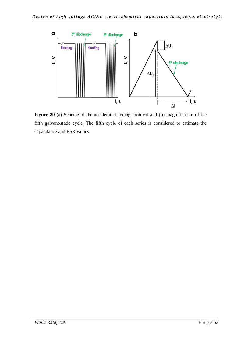
D e s i g n o f h i g h v o l t a g e A C / A C e l e c t r o c h e m i c a l c a p a c i t o r s i n a q u e o u s e l e c t r o l y t e
Paula Ratajczak P a g e 62
Figure 29 (a) Scheme of the accelerated ageing protocol and (b) magnification of the
fifth galvanostatic cycle. The fifth cycle of each series is considered to estimate the
capacitance and ESR values.
D e s i g n o f h i g h v o l t a g e A C / A C e l e c t r o c h e m i c a l c a p a c i t o r s i n a q u e o u s e l e c t r o l y t e
Paula Ratajczak P a g e 63
CHAPTER III
STATE OF HEALTH
OF AQUEOUS ELECTROCHEMICAL CAPACITORS
WITH STAINLESS STEEL CURRENT COLLECTORS
UNDER ACCELERATED AGEING
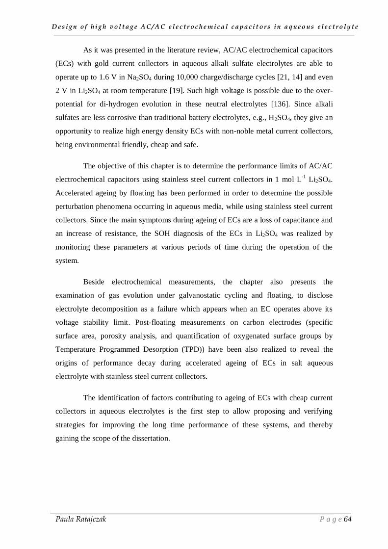
D e s i g n o f h i g h v o l t a g e A C / A C e l e c t r o c h e m i c a l c a p a c i t o r s i n a q u e o u s e l e c t r o l y t e
Paula Ratajczak P a g e 64
As it was presented in the literature review, AC/AC electrochemical capacitors
(ECs) with gold current collectors in aqueous alkali sulfate electrolytes are able to
operate up to 1.6 V in Na2SO4 during 10,000 charge/discharge cycles [21, 14] and even
2 V in Li2SO4 at room temperature [19]. Such high voltage is possible due to the over-
potential for di-hydrogen evolution in these neutral electrolytes [136]. Since alkali
sulfates are less corrosive than traditional battery electrolytes, e.g., H2SO4, they give an
opportunity to realize high energy density ECs with non-noble metal current collectors,
being environmental friendly, cheap and safe.
The objective of this chapter is to determine the performance limits of AC/AC
electrochemical capacitors using stainless steel current collectors in 1 mol L-1
Li2SO4.
Accelerated ageing by floating has been performed in order to determine the possible
perturbation phenomena occurring in aqueous media, while using stainless steel current
collectors. Since the main symptoms during ageing of ECs are a loss of capacitance and
an increase of resistance, the SOH diagnosis of the ECs in Li2SO4 was realized by
monitoring these parameters at various periods of time during the operation of the
system.
Beside electrochemical measurements, the chapter also presents the
examination of gas evolution under galvanostatic cycling and floating, to disclose
electrolyte decomposition as a failure which appears when an EC operates above its
voltage stability limit. Post-floating measurements on carbon electrodes (specific
surface area, porosity analysis, and quantification of oxygenated surface groups by
Temperature Programmed Desorption (TPD)) have been also realized to reveal the
origins of performance decay during accelerated ageing of ECs in salt aqueous
electrolyte with stainless steel current collectors.
The identification of factors contributing to ageing of ECs with cheap current
collectors in aqueous electrolytes is the first step to allow proposing and verifying
strategies for improving the long time performance of these systems, and thereby
gaining the scope of the dissertation.

D e s i g n o f h i g h v o l t a g e A C / A C e l e c t r o c h e m i c a l c a p a c i t o r s i n a q u e o u s e l e c t r o l y t e
Paula Ratajczak P a g e 65
III.1. High voltage ageing assessment of AC/AC
electrochemical capacitors in lithium sulfate electrolyte
For the present study, a commercially available activated carbon powder (DLC
Super 30, Norit, further named S30), with a specific surface area of 1843 m2 g
-1, has
been chosen as active electrode material (see experimental annex A.1.1). The pore size
distribution (Figure A1b) indicates that the micropores of this carbon are essentially in
the region of 0.8-0.9 nm; the carbon exhibits also some mesoporosity needed for
enhanced charge propagation. The Temperature Programmed Desorption (TPD)
analysis (Table A2) reveals a small amount of oxygenated functionalities on the surface
of S30, with relatively low oxygen amount of 1.5 wt %.
1.1. Exploring the high operating voltage of AC/AC
electrochemical capacitors in lithium sulfate electrolyte
In order to estimate the maximum operating voltage of ECs with stainless steel
current collectors in 1 mol L-1
Li2SO4, the electrodes potential limits were determined
by galvanostatic (200 mA g-1
) cycling on a two-electrode assembly with reference
electrode, and were plotted vs voltage (Figure 30). The practical di-hydrogen evolution
potential represented by a horizontal line at around -0.8 V vs NHE on this figure was
determined by the oscillations due to bubbling on three-electrode CVs, as shown in
Figure 20 in the literature part. This potential is much lower than the thermodynamic at
pH = 6.5 (E- = -0.384 V vs NHE). This is due to the reduction of water and production
of OH-, which accordingly to the Nernst law results in an increase of local pH in the
pores of S30. As seen in Figure 30, whatever the value of voltage up to 1.6 V, the
lowest potential of the negative electrode is always higher than -0.8 V vs NHE, which
means that di-hydrogen evolution at this electrode might be considered as negligible. By
contrast, the positive S30 electrode operates below the thermodynamic water oxidation
limit (marked by the upper dashed line) only up to a voltage of 1.4 V. Above the latter
value, one might expect detrimental oxidation of the positive S30 electrode. In other
words, these measurements suggest an approximate maximum operating voltage of 1.4
V for the S30/S30 cell in 1 mol L-1
Li2SO4.

D e s i g n o f h i g h v o l t a g e A C / A C e l e c t r o c h e m i c a l c a p a c i t o r s i n a q u e o u s e l e c t r o l y t e
Paula Ratajczak P a g e 66
Figure 30 Electrodes potential extrema vs voltage measured during galvanostatic (200
mA g-1
) cycling on an S30/S30 capacitor with stainless steel collectors in 1 mol L-1
Li2SO4. EOCP- open circuit potential.
Figure 31 shows the cyclic voltammograms of the individual electrodes recorded
in the potential ranges determined during galvanostatic cycling of the S30/S30 cell with
reference electrode in 1 mol L-1
Li2SO4 (see Figure 30). The CVs in Figure 31 prove
that, even at voltage of 1.6 V, the lowest potential of the negative electrode is always
higher than the practical di-hydrogen evolution potential (-0.8 vs. NHE), where
oscillations on the curves would be visible. By contrast, an anodic current leap together
with a corresponding cathodic wave appears for the positive electrode, as the potential
for oxygen evolution (0.845 V vs. NHE) is exceeded. The anodic peak might be also
related to the electrochemical oxidation of the carbon electrode [188], the redox
reactions between the generated oxygenated surface groups and the electrolyte [131],
and the corrosion of the positive stainless steel current collector.
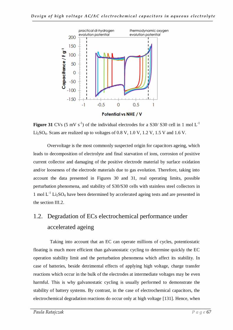
D e s i g n o f h i g h v o l t a g e A C / A C e l e c t r o c h e m i c a l c a p a c i t o r s i n a q u e o u s e l e c t r o l y t e
Paula Ratajczak P a g e 67
Figure 31 CVs (5 mV s-1
) of the individual electrodes for a S30/ S30 cell in 1 mol L-1
Li2SO4. Scans are realized up to voltages of 0.8 V, 1.0 V, 1.2 V, 1.5 V and 1.6 V.
Overvoltage is the most commonly suspected origin for capacitors ageing, which
leads to decomposition of electrolyte and final starvation of ions, corrosion of positive
current collector and damaging of the positive electrode material by surface oxidation
and/or looseness of the electrode materials due to gas evolution. Therefore, taking into
account the data presented in Figures 30 and 31, real operating limits, possible
perturbation phenomena, and stability of S30/S30 cells with stainless steel collectors in
1 mol L-1
Li2SO4 have been determined by accelerated ageing tests and are presented in
the section III.2.
1.2. Degradation of ECs electrochemical performance under
accelerated ageing
Taking into account that an EC can operate millions of cycles, potentiostatic
floating is much more efficient than galvanostatic cycling to determine quickly the EC
operation stability limit and the perturbation phenomena which affect its stability. In
case of batteries, beside detrimental effects of applying high voltage, charge transfer
reactions which occur in the bulk of the electrodes at intermediate voltages may be even
harmful. This is why galvanostatic cycling is usually performed to demonstrate the
stability of battery systems. By contrast, in the case of electrochemical capacitors, the
electrochemical degradation reactions do occur only at high voltage [131]. Hence, when
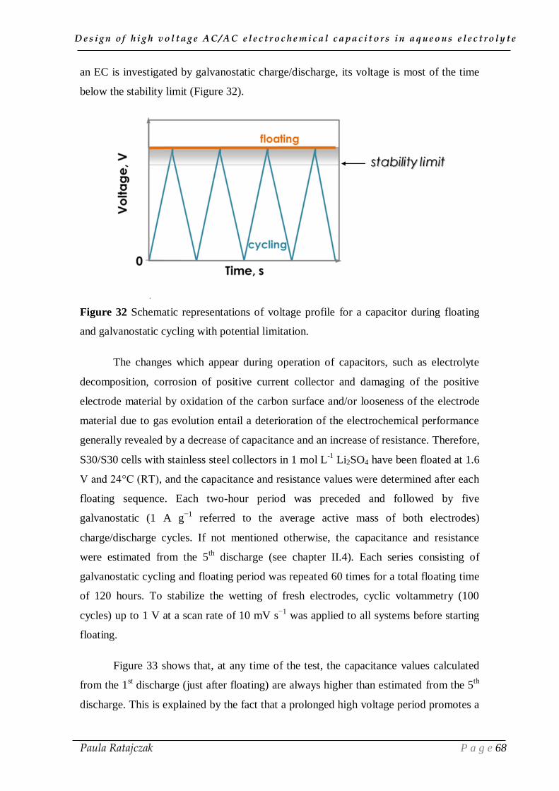
D e s i g n o f h i g h v o l t a g e A C / A C e l e c t r o c h e m i c a l c a p a c i t o r s i n a q u e o u s e l e c t r o l y t e
Paula Ratajczak P a g e 68
an EC is investigated by galvanostatic charge/discharge, its voltage is most of the time
below the stability limit (Figure 32).
Figure 32 Schematic representations of voltage profile for a capacitor during floating
and galvanostatic cycling with potential limitation.
The changes which appear during operation of capacitors, such as electrolyte
decomposition, corrosion of positive current collector and damaging of the positive
electrode material by oxidation of the carbon surface and/or looseness of the electrode
material due to gas evolution entail a deterioration of the electrochemical performance
generally revealed by a decrease of capacitance and an increase of resistance. Therefore,
S30/S30 cells with stainless steel collectors in 1 mol L-1
Li2SO4 have been floated at 1.6
V and 24°C (RT), and the capacitance and resistance values were determined after each
floating sequence. Each two-hour period was preceded and followed by five
galvanostatic (1 A g−1
referred to the average active mass of both electrodes)
charge/discharge cycles. If not mentioned otherwise, the capacitance and resistance
were estimated from the 5th
discharge (see chapter II.4). Each series consisting of
galvanostatic cycling and floating period was repeated 60 times for a total floating time
of 120 hours. To stabilize the wetting of fresh electrodes, cyclic voltammetry (100
cycles) up to 1 V at a scan rate of 10 mV s−1
was applied to all systems before starting
floating.
Figure 33 shows that, at any time of the test, the capacitance values calculated
from the 1st discharge (just after floating) are always higher than estimated from the 5
th
discharge. This is explained by the fact that a prolonged high voltage period promotes a
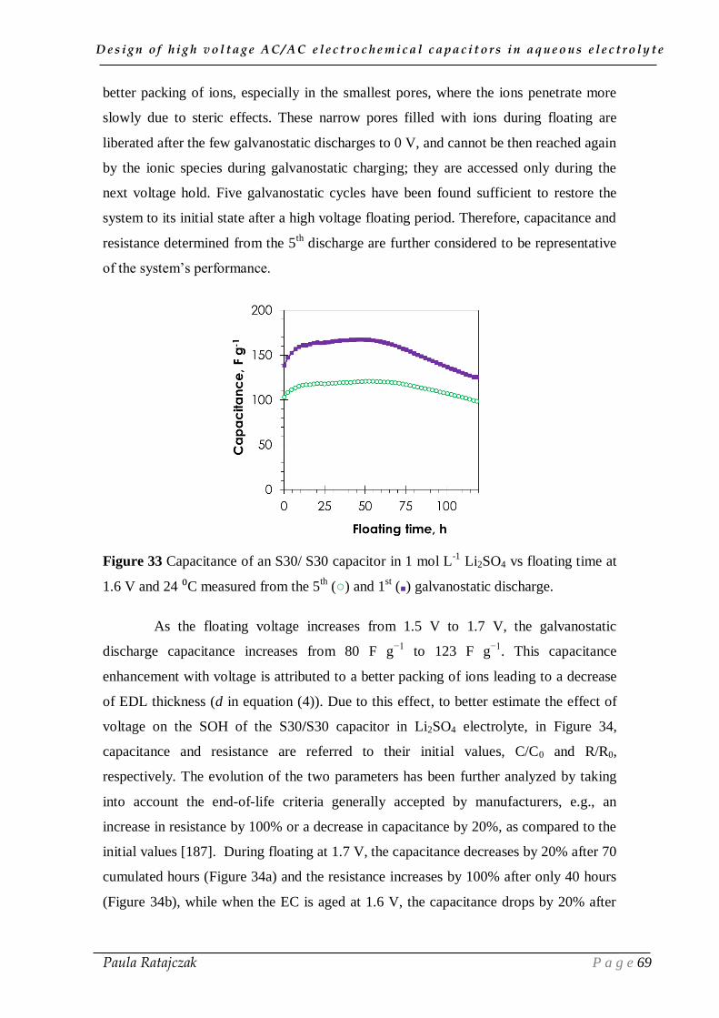
D e s i g n o f h i g h v o l t a g e A C / A C e l e c t r o c h e m i c a l c a p a c i t o r s i n a q u e o u s e l e c t r o l y t e
Paula Ratajczak P a g e 69
better packing of ions, especially in the smallest pores, where the ions penetrate more
slowly due to steric effects. These narrow pores filled with ions during floating are
liberated after the few galvanostatic discharges to 0 V, and cannot be then reached again
by the ionic species during galvanostatic charging; they are accessed only during the
next voltage hold. Five galvanostatic cycles have been found sufficient to restore the
system to its initial state after a high voltage floating period. Therefore, capacitance and
resistance determined from the 5th
discharge are further considered to be representative
of the system’s performance.
Figure 33 Capacitance of an S30/ S30 capacitor in 1 mol L-1
Li2SO4 vs floating time at
1.6 V and 24 ⁰C measured from the 5th () and 1
st () galvanostatic discharge.
As the floating voltage increases from 1.5 V to 1.7 V, the galvanostatic
discharge capacitance increases from 80 F g−1
to 123 F g−1
. This capacitance
enhancement with voltage is attributed to a better packing of ions leading to a decrease
of EDL thickness (d in equation (4)). Due to this effect, to better estimate the effect of
voltage on the SOH of the S30/S30 capacitor in Li2SO4 electrolyte, in Figure 34,
capacitance and resistance are referred to their initial values, C/C0 and R/R0,
respectively. The evolution of the two parameters has been further analyzed by taking
into account the end-of-life criteria generally accepted by manufacturers, e.g., an
increase in resistance by 100% or a decrease in capacitance by 20%, as compared to the
initial values [187]. During floating at 1.7 V, the capacitance decreases by 20% after 70
cumulated hours (Figure 34a) and the resistance increases by 100% after only 40 hours
(Figure 34b), while when the EC is aged at 1.6 V, the capacitance drops by 20% after

D e s i g n o f h i g h v o l t a g e A C / A C e l e c t r o c h e m i c a l c a p a c i t o r s i n a q u e o u s e l e c t r o l y t e
Paula Ratajczak P a g e 70
120 h and the resistance is doubled after 50 h. Consequently, the cells aged at 1.6 V and
1.7 V are no longer in good SOH after 50 and 40 hours, respectively. It is interesting to
notice that, in both cases, the lifetime is controlled essentially by the increase of
resistance. It means that one can suspect parasitic phenomena altering the contacts
between the active material and the current collectors or between the carbon particles
themselves in the electrodes, due for example to corrosion of current collectors or gas
evolution.
When the floating voltage is reduced to 1.5 V, the SOH of the cell is still
excellent after a long period of 120 hours. The progressive increase of capacitance with
floating time is attributed to the progressive penetration of ions in pores of small size.
As compared to 1.6 V or 1.7 V floating, the increase of resistance after floating at 1.5 V
is much smaller. However, its slight increase still reveals some detrimental effects,
which will be further presented in the next sections of this manuscript. Notwithstanding,
the stability voltage determined by floating fits quite well with the conclusions driven
from Figures 30 and 31, and regarding effect of oxidation on the positive electrode data.
Figure 34 Effect of the floating voltage at 24 ⁰C on (a) relative capacitance and (b)
relative resistance of an S30/ S30 EC in 1 mol L
-1 Li2SO4.
To perceive dissimilarities between the impacts of galvanostatic cycling and
floating on ageing, the capacitance and resistance of the S30/S30 electrochemical
capacitor (with stainless steel collectors in 1 mol L-1
Li2SO4) has been plotted during
galvanostatic cycling up to 1.6 V or floating at 1.6 V (Figure 35). The voltage of 1.6 V

D e s i g n o f h i g h v o l t a g e A C / A C e l e c t r o c h e m i c a l c a p a c i t o r s i n a q u e o u s e l e c t r o l y t e
Paula Ratajczak P a g e 71
has been selected in light of Figure 34 which revealed that detrimental reactions are
negligible during floating at lower voltage. Figure 35 shows that the capacitance
decreases by 6% after 285 hours (10,000 galvanostatic cycles) at a current density of 1
A g-1
(Figure 35a), while for the cell aged by floating, the capacitance loss of 6% is
evidenced after only 124 hours (55th floating series). Despite the capacitance packing
occurring at the beginning of floating and leading to a transient increase of capacitance,
the time for reducing the capacitance by 6% is shorter than in galvanostatic cycling. The
efficiency of floating for ageing the cell, as compared to galvanostatic cycling, would be
even amplified if the investigation time would be extended. The poor effectiveness of
galvanostatic cycling is well-illustrated by Figure 32, showing that the time at high
voltage to provoke degradation phenomena in the cell is extremely short. This time is
even shorter, because the imposed voltage is not reached due to the ohmic drop (in the
present case, the ohmic drop at current density of 1 A g-1
is 8 mV). The acceleration of
cells’ ageing can be even easier seen by comparison of resistance evolution of the two
cells (Figure 35b). For the system aged by galvanostatic cycling, the resistance is very
stable until the end of the test, whilst R/R0 increases just from the initial 2-hour floating
sequence at 1.6 V.
Figure 35 Comparison of stability performance of S30/ S30 cells in 1 mol L-1
Li2SO4
during floating at 1.6 V and galvanostatic (1 A g-1
) cycling up to 1.6 V: (a) capacitance
and (b) resistance evolution.
Notwithstanding, Figure 35 reveals differences in the profiles of capacitance
and resistance evolution depending on the ageing procedure, either by GCPL or by
floating. As observed previously for the cells floated at 1.5, 1.6 and 1.7 V (Figure 34),

D e s i g n o f h i g h v o l t a g e A C / A C e l e c t r o c h e m i c a l c a p a c i t o r s i n a q u e o u s e l e c t r o l y t e
Paula Ratajczak P a g e 72
the capacitance of the cells initially increases, due to a better wetting of the electrodes
by the electrolyte during prolonged polarization, allowing narrow pores to be accessed
by ions. The initial capacitance enhancement could be also the result of electrostatic
field modification on the electrode surface due to an increase in oxygen content,
allowing the micropores to be more easily wetted by the ions from the aqueous
electrolyte [189, 82, 83]. When all accessible pores are reached by floating at 1.6 V, the
capacitance remains almost constant for a period of time, until it starts to decay
continuously after 50 hours of floating (Figure 35), indicating a progressive ageing of
the system, which is the most probably due to the reduction of accessible surface area of
the S30 electrodes. Therefore, due to this kind of capacitance and resistance evolution
profile, depending on the ageing procedure, it is not easy to establish a correlation
between a 2-hour floating period and a number of corresponding galvanostatic cycles.
To appreciate the importance of side reactions contributing to ageing by floating,
it is interesting to compare the evolution of leakage current (LC) during 60 repeated
sequences at 1.5 and 1.6 V (Figure 36) [3]. As shown in Figure 36a, during
potentiostatic floating, the leakage current rapidly decreases within a few minutes and
then stabilizes at an equilibrium value. The LC drop is related to the structure of the
double-layer formed at the electrode/electrolyte interface during charging. As
mentioned before, according to the Grahame double-layer model, the EDL consists of:
(i) a diffusion layer, with ions weakly interacting with the carbon electrode, (ii) and a
compact layer where ions strongly interact with the electrode [8]. The dramatic current
decay originates from the loss of charge, when weakly interacting ions flow to the bulk
of the electrolyte. As the floating time proceeds, the ions of the diffusion layer are
pushed to the compact layer, and the structure of the EDL is ordered, until reaching
equilibrium [190]. However, in an electrochemical capacitor, the electrodes are made of
a porous network which hinders so simple charge exchange; moreover, in the confined
volume of micropore, the traditional models of the EDL are not applicable.
The initial values of leakage current measured at the beginning of each floating
sequence at 1.6 V increase with the number of floating periods, indicating a slower
transition from galvanostatic charging current to leakage current. The equilibrium
leakage current itself reveals the occurrence of side reactions: the higher its value, the
higher amount of charge contributes to side reactions [3]. While the profile of
equilibrium leakage current is almost constant during ageing at 1.5 V, it can be observed
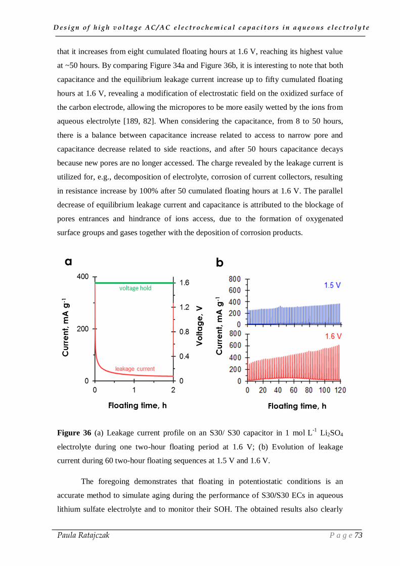
D e s i g n o f h i g h v o l t a g e A C / A C e l e c t r o c h e m i c a l c a p a c i t o r s i n a q u e o u s e l e c t r o l y t e
Paula Ratajczak P a g e 73
that it increases from eight cumulated floating hours at 1.6 V, reaching its highest value
at ~50 hours. By comparing Figure 34a and Figure 36b, it is interesting to note that both
capacitance and the equilibrium leakage current increase up to fifty cumulated floating
hours at 1.6 V, revealing a modification of electrostatic field on the oxidized surface of
the carbon electrode, allowing the micropores to be more easily wetted by the ions from
aqueous electrolyte [189, 82]. When considering the capacitance, from 8 to 50 hours,
there is a balance between capacitance increase related to access to narrow pore and
capacitance decrease related to side reactions, and after 50 hours capacitance decays
because new pores are no longer accessed. The charge revealed by the leakage current is
utilized for, e.g., decomposition of electrolyte, corrosion of current collectors, resulting
in resistance increase by 100% after 50 cumulated floating hours at 1.6 V. The parallel
decrease of equilibrium leakage current and capacitance is attributed to the blockage of
pores entrances and hindrance of ions access, due to the formation of oxygenated
surface groups and gases together with the deposition of corrosion products.
Figure 36 (a) Leakage current profile on an S30/ S30 capacitor in 1 mol L
-1 Li2SO4
electrolyte during one two-hour floating period at 1.6 V; (b) Evolution of leakage
current during 60 two-hour floating sequences at 1.5 V and 1.6 V.
The foregoing demonstrates that floating in potentiostatic conditions is an
accurate method to simulate aging during the performance of S30/S30 ECs in aqueous
lithium sulfate electrolyte and to monitor their SOH. The obtained results also clearly

D e s i g n o f h i g h v o l t a g e A C / A C e l e c t r o c h e m i c a l c a p a c i t o r s i n a q u e o u s e l e c t r o l y t e
Paula Ratajczak P a g e 74
reveal that GCPL with a limited number of cycles (ca 10,000) is definitively not an
accurate test to determine the maximum operating voltage of ECs. Notwithstanding, the
differences in the profiles of capacitance and resistance evolution depending on the
ageing procedure at 1.6 V, either by GCPL or by floating, disclose that it would be
inaccurate to estimate the floating ageing time corresponding to a given number of
galvanostatic cycles.
Nevertheless, the performed experiments allowed to assess that S30/S30 ECs in
1 mol L-1
lithium sulfate can operate with a very long cycle life at voltage as high as 1.5
V. At the same time, they indicate that most of the claims in the literature have to be
considered with great care, meaning that the mentioned voltage values should be
reduced by around 0.3–0.4 V, especially when gold current collectors were used.
Notwithstanding, the voltage value of 1.5 V is still remarkably high for an aqueous
electrolyte compared to only 0.7–0.8 V generally possible for KOH or H2SO4
electrolytes. However, to move towards further optimization of the high voltage AC/AC
ECs with stainless steel collectors in aqueous 1 mol L-1
Li2SO4, the possible
perturbation phenomena under long time operation must be identified.
III.2. Factors contributing to ageing in aqueous electrolyte
As presented in section III.1, the long term operation of an EC in 1 mol L-1
Li2SO4 at voltages higher than 1.5 V leads to ageing of the components, revealed by a
drop of capacitance and an increase of resistance (Figure 34). The plot of leakage
current evolution during repeated floating sequences at 1.6 V (Figure 36b) indicates the
occurrence of side reactions which contribute to ageing.
2. 1. Oxidation of carbon electrodes and corrosion of stainless
steel current collectors
2.1.1. Post-floating analysis of ECs by electrochemical techniques
We have used electrochemical impedance spectroscopy (EIS) to distinguish the
origins of electrode degradation processes, such as electrolyte decomposition, and other
possible perturbation phenomena (i.e., oxidation of S30 electrode and/or corrosion of
stainless steel collectors, internal pressure evolution). EIS data at open circuit voltage
(OCV) have been compared for a freshly built cell with S30 electrodes in 1 mol L−1

D e s i g n o f h i g h v o l t a g e A C / A C e l e c t r o c h e m i c a l c a p a c i t o r s i n a q u e o u s e l e c t r o l y t e
Paula Ratajczak P a g e 75
Li2SO4 and after 120 hours of ageing at 1.6 V (Figure 37). Due to floating, the ESR of
the system increases from 0.7 to 1.1 Ω, suggesting a more resistive path of ions in the
active surface of S30 and probably worse contact between the grains of S30 due to gas
evolution. The increase of equivalent distributed resistance (EDR) causes a decrease of
the slope in the low frequency branch and is attributed to the limited penetration of ions
in the pores of electrodes due to side reactions. Moreover, the presence of a constant
phase element (CPE) visible by deviation from the pure capacitive vertical impedance
response at low frequencies (Figure 37a) indicates a non-uniform thickness of the
double-layer, inhomogeneity or adsorption processes [186]. The increase of interfacial
charge transfer resistance Rf from 1.2 to 24.9 Ω results probably from an uneven
distribution of current in the positive electrode, due to the appearance of corrosion
products. The shift in transition from the high frequency semicircle to the mid-
frequency distributed charge storage impedance region suggests time dependence in the
charging process, probably as a result of a low conducting layer formed by corrosion
products.
The capacitance vs frequency dependence (Figure 37b) reveals almost constant
capacitance at low frequency for the fresh cell, which exhibits a typical EDLC behavior.
The almost ideal performance of the system in the initial state is confirmed in the Bode
plots by phase angle values very close to -90° at low frequency (Figure 37c). After 120
floating hours, the capacitance is higher than before ageing (107 F g−1
compared to 73 F
g-1
) at the lowest frequencies, and it decreases more rapidly than of the fresh cell in the
frequency range 0.1 Hz–1 Hz (phase close to 0). The higher capacitance values
measured up to 0.1 Hz for the aged cell originate from faradaic contribution, probably
due to a conductive layer of corrosion products and oxygenated surface functionalities
on the S30 electrode. Since EIS does not involve current and potential variations, it
allows distinguishing the phenomena occurring in the porosity of electrodes (at high
frequencies) and at the electrode/current collector interface (at low frequencies).
Contrariwise, in the transient techniques by measuring current or potential response (CV
and GCPL), the changes in the electric field of each component of the EC cannot be
differentiated. Therefore, for the aged cell, the capacitance value of 107 F g−1
determined by EIS at the electrode/current collector interface is not disclosed by CV or
GCPL, where the capacitance decrease related to blocked porosity of S30 is dominant.
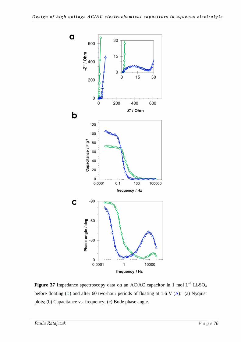
D e s i g n o f h i g h v o l t a g e A C / A C e l e c t r o c h e m i c a l c a p a c i t o r s i n a q u e o u s e l e c t r o l y t e
Paula Ratajczak P a g e 76
Figure 37 Impedance spectroscopy data on an AC/AC capacitor in 1 mol L
-1 Li2SO4
before floating () and after 60 two-hour periods of floating at 1.6 V (Δ): (a) Nyquist
plots; (b) Capacitance vs. frequency; (c) Bode phase angle.

D e s i g n o f h i g h v o l t a g e A C / A C e l e c t r o c h e m i c a l c a p a c i t o r s i n a q u e o u s e l e c t r o l y t e
Paula Ratajczak P a g e 77
The time constant τ for the fresh and aged cells, calculated at the frequency
where reactance and resistance are equal (-45 phase angle) (Figure 37c) [119], is 4 s
and 100 s, respectively, showing an important decay after ageing and confirming
deleterious changes of the S30/S30 system in lithium sulfate electrolyte after ageing at
1.6 V at room temperature.
In order to analyze the energy storage abilities of ECs after ageing at 1.5 V and
1.7 V, cyclic voltammetry (10 mV s-1
) was used to record the capacitive current
variations (Figure 38). The fresh cells display a typical rectangular shape of CV,
whereas after each 20 series of floating sequences at 1.5 and 1.7 V the ECs exhibit a
more resistive character by an inclined voltammogram; the increase of capacitive
current at low voltage values could be attributed to pseudo-capacitive contributions
related with the creation of surface oxygenated groups on the positive carbon electrode.
Considering the CV curves recorded up to the ageing voltage of 1.5 V (Figure 38c) and
1.7 V (Figure 38d), the diminishing of capacitive current at voltage higher than 1 V
negatively affects the deliverable energy and power density. The capacitance decrease
and resistance increase can be attributed to electrolyte starvation as a consequence of
reduced ion availability [191]. Indeed, due to electrolyte decomposition, the electrolyte
reservoir decreases, and is finally not sufficient to cover the working surface area of
electrodes at higher voltages. The second possible explanation for the narrowing of
CVs, as voltage increases, is the saturation of the electrode material porosity by the
stored ions. The deposition of decomposition/corrosion products in the porosity of the
positive electrode and/or the formation of surface oxygenated groups reduces the S30
accessible pore volume for ions, thus leading to a fade of capacitive current at voltages
higher than 1 V [192]. Furthermore, the formation of such products results in an
increase of the leakage resistance (Rf), due to worse charge propagation after 20 floating
series at 1.7 V (Figure 38b, d). The phenomenon is not pronounced for the cell aged at
1.5 V; however, the slight saturation of the carbon porosity by the stored ions during the
prolonged high voltage period discloses a detrimental effect of 1.5 V for the deliverable
energy and power density after even 20 series of accelerated ageing.

D e s i g n o f h i g h v o l t a g e A C / A C e l e c t r o c h e m i c a l c a p a c i t o r s i n a q u e o u s e l e c t r o l y t e
Paula Ratajczak P a g e 78
Figure 38 Cyclic voltammograms (10 mV s-1
scan rate) recorded after each 20 series of
two-hour floating sequences (a and c) at 1.5 V and (b and d) at 1.7 V on a S30/ S30
capacitor in 1 mol L-1
Li2SO4.
2.1.2. Post-floating analyses on carbon electrodes
To explain the above demonstrated changes in electrochemical performance of
the aged ECs, the oxygenated surface functionality of aged electrodes has been
characterized and quantified by Temperature Programmed Desorption (TPD). To avoid
the interference of the electrode binder during the post-floating analysis of electrodes by
TPD, self-standing electrodes from activated carbon cloth (ACC 507-20, Kynol,
SBET=2231 m2 g
-1 and L0=0.99 nm) were selected. The TPD analyses have been realized
in helium atmosphere at 20 °C min-1
up to 950 °C, on the pristine ACC, the positive and
negative aged ACC electrodes treated. Figure 39 presents the mass loss, and CO2 and
CO profiles obtained by TPD for the fresh ACC and the positive and negative electrodes
extracted from the EC after 120 floating hours at 1.7 V. The important weight loss at
950 °C for the positive carbon electrode is related to an important surface oxidation and
formation of functionalities evolving essentially as CO2 together with a lesser amount of
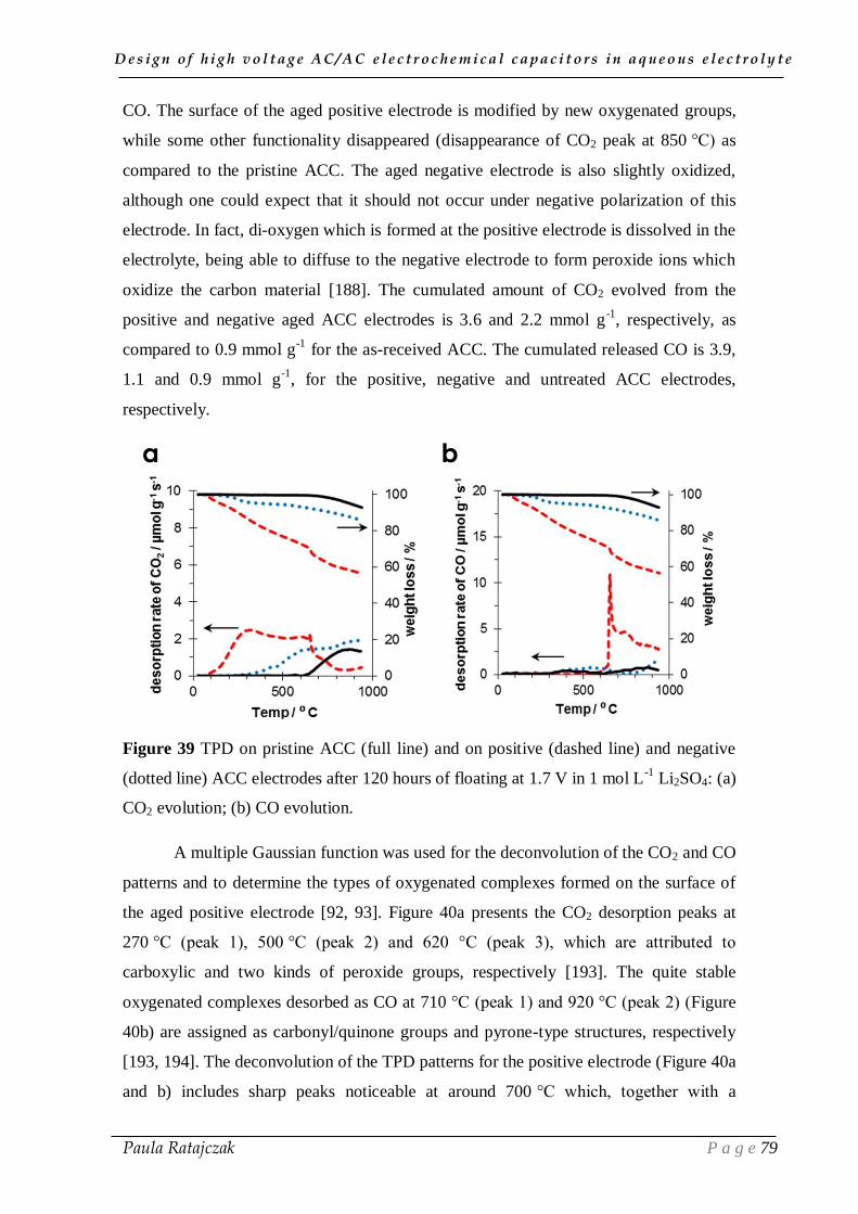
D e s i g n o f h i g h v o l t a g e A C / A C e l e c t r o c h e m i c a l c a p a c i t o r s i n a q u e o u s e l e c t r o l y t e
Paula Ratajczak P a g e 79
CO. The surface of the aged positive electrode is modified by new oxygenated groups,
while some other functionality disappeared (disappearance of CO2 peak at 850 °C) as
compared to the pristine ACC. The aged negative electrode is also slightly oxidized,
although one could expect that it should not occur under negative polarization of this
electrode. In fact, di-oxygen which is formed at the positive electrode is dissolved in the
electrolyte, being able to diffuse to the negative electrode to form peroxide ions which
oxidize the carbon material [188]. The cumulated amount of CO2 evolved from the
positive and negative aged ACC electrodes is 3.6 and 2.2 mmol g-1
, respectively, as
compared to 0.9 mmol g-1
for the as-received ACC. The cumulated released CO is 3.9,
1.1 and 0.9 mmol g-1
, for the positive, negative and untreated ACC electrodes,
respectively.
Figure 39 TPD on pristine ACC (full line) and on positive (dashed line) and negative
(dotted line) ACC electrodes after 120 hours of floating at 1.7 V in 1 mol L-1
Li2SO4: (a)
CO2 evolution; (b) CO evolution.
A multiple Gaussian function was used for the deconvolution of the CO2 and CO
patterns and to determine the types of oxygenated complexes formed on the surface of
the aged positive electrode [92, 93]. Figure 40a presents the CO2 desorption peaks at
270 °C (peak 1), 500 °C (peak 2) and 620 °C (peak 3), which are attributed to
carboxylic and two kinds of peroxide groups, respectively [193]. The quite stable
oxygenated complexes desorbed as CO at 710 °C (peak 1) and 920 °C (peak 2) (Figure
40b) are assigned as carbonyl/quinone groups and pyrone-type structures, respectively
[193, 194]. The deconvolution of the TPD patterns for the positive electrode (Figure 40a
and b) includes sharp peaks noticeable at around 700 °C which, together with a
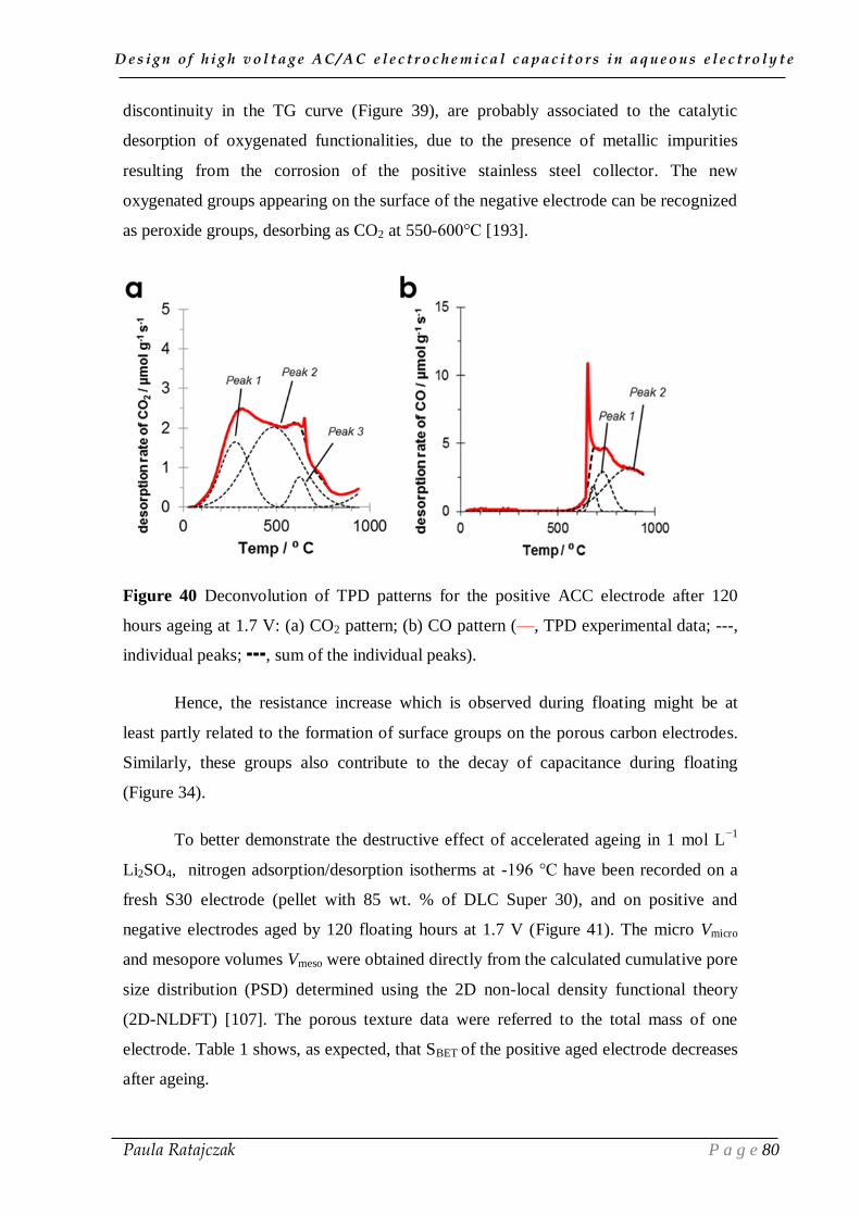
D e s i g n o f h i g h v o l t a g e A C / A C e l e c t r o c h e m i c a l c a p a c i t o r s i n a q u e o u s e l e c t r o l y t e
Paula Ratajczak P a g e 80
discontinuity in the TG curve (Figure 39), are probably associated to the catalytic
desorption of oxygenated functionalities, due to the presence of metallic impurities
resulting from the corrosion of the positive stainless steel collector. The new
oxygenated groups appearing on the surface of the negative electrode can be recognized
as peroxide groups, desorbing as CO2 at 550-600°C [193].
Figure 40 Deconvolution of TPD patterns for the positive ACC electrode after 120
hours ageing at 1.7 V: (a) CO2 pattern; (b) CO pattern (—, TPD experimental data; ---,
individual peaks; , sum of the individual peaks).
Hence, the resistance increase which is observed during floating might be at
least partly related to the formation of surface groups on the porous carbon electrodes.
Similarly, these groups also contribute to the decay of capacitance during floating
(Figure 34).
To better demonstrate the destructive effect of accelerated ageing in 1 mol L−1
Li2SO4, nitrogen adsorption/desorption isotherms at -196 °C have been recorded on a
fresh S30 electrode (pellet with 85 wt. % of DLC Super 30), and on positive and
negative electrodes aged by 120 floating hours at 1.7 V (Figure 41). The micro Vmicro
and mesopore volumes Vmeso were obtained directly from the calculated cumulative pore
size distribution (PSD) determined using the 2D non-local density functional theory
(2D-NLDFT) [107]. The porous texture data were referred to the total mass of one
electrode. Table 1 shows, as expected, that SBET of the positive aged electrode decreases
after ageing.
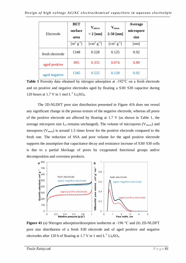
D e s i g n o f h i g h v o l t a g e A C / A C e l e c t r o c h e m i c a l c a p a c i t o r s i n a q u e o u s e l e c t r o l y t e
Paula Ratajczak P a g e 81
Electrode
BET
surface
area
Vmicro
< 2 [nm]
Vmeso
2-50 [nm]
Average
micropore
size
[m2 g
-1] [cm
3 g
-1] [cm
3 g
-1] [nm]
fresh electrode 1348 0.528 0.125 0.92
aged positive 895 0.355 0.074 0.89
aged negative 1345 0.525 0.128 0.92
Table 1 Porosity data obtained by nitrogen adsorption at -192°C on a fresh electrode
and on positive and negative electrodes aged by floating a S30/ S30 capacitor during
120 hours at 1.7 V in 1 mol L-1
Li2SO4.
The 2D-NLDFT pore size distribution presented in Figure 41b does not reveal
any significant change in the porous texture of the negative electrode, whereas all pores
of the positive electrode are affected by floating at 1.7 V (as shown in Table 1, the
average micropore size L0 remains unchanged). The volume of micropores (Vmicro) and
mesopores (Vmeso) is around 1.5 times lower for the positive electrode compared to the
fresh one. The reduction of SSA and pore volume for the aged positive electrode
supports the assumption that capacitance decay and resistance increase of S30/ S30 cells
is due to a partial blockage of pores by oxygenated functional groups and/or
decomposition and corrosion products.
Figure 41 (a) Nitrogen adsorption/desorption isotherms at -196 °C and (b) 2D-NLDFT
pore size distribution of a fresh S30 electrode and of aged positive and negative
electrodes after 120 h of floating at 1.7 V in 1 mol L-1
Li2SO4.

D e s i g n o f h i g h v o l t a g e A C / A C e l e c t r o c h e m i c a l c a p a c i t o r s i n a q u e o u s e l e c t r o l y t e
Paula Ratajczak P a g e 82
2.1.3. Effect of temperature on ageing
Since the application of 1.7 V potentiostatic floating was found to be deleterious
for the positive electrode, and consequently for the cell, and accelerated ageing at 1.5 V
indicates no important resistance increase after 120 hours at 24 °C (Figure 34b), we
have investigated the effect of raising the temperature to 35 °C and 40 °C, while
floating at 1.5 V. After ageing a S30/S30 capacitor in 1 mol L-1
Li2SO4 at 1.5 V and 40
°C and opening the cell, a russet colour attributed to corrosion has been perceived
essentially on the positive stainless steel current collector and on the separator (Figure
42).
Figure 42 Corroded components of a S30/ S30 capacitor in 1 mol L-1
Li2SO4 after 120
hours of floating at 1.5 V and 40°C.
Figure 42 shows the effect of floating at 1.5 V and different temperatures on
relative capacitance and resistance evolution of S30/ S30 cells in 1 mol L-1
Li2SO4; for
comparison, the data of Figure 34 obtained at 24°C are also reported. During the first 50
hours of floating at 1.5 V and 40 °C, the capacitance increases while resistance slightly
decreases. Such behaviour is attributed to a better mobility of ions at higher
temperature, which enhances the electrolyte penetration in the porosity of S30.
However, as the floating time proceeds at 40 °C, the capacitance starts to decline and

D e s i g n o f h i g h v o l t a g e A C / A C e l e c t r o c h e m i c a l c a p a c i t o r s i n a q u e o u s e l e c t r o l y t e
Paula Ratajczak P a g e 83
the resistance increases more rapidly than at lower temperature, at which the parasitic
reactions in the system are reduced. Nonetheless, it is important to notice, that even at
1.5 V, the perturbation phenomena are triggered when increasing the temperature by
around 15 °C. These so-called perturbations are essentially related to electrolyte
decomposition, which leads to carbon oxidation and decreases its conductivity, and the
formation of corrosion products at the interface between the current collector and the
carbon electrode. Therefore, gas evolution has been monitored during cycling and
accelerated ageing at RT, 35 °C and 40 °C, and is presented in part 2.2.
Figure 43 Effect of temperature increase on the accelerated ageing of S30/ S30
capacitors in 1 mol L
-1 Li2SO4 at 1.5 V: (a) relative capacitance; (b) relative resistance.
2.2. Gas evolution during floating
At positive electrode potential higher than the value for electrolyte oxidation,
gases such as di-oxygen, CO and CO2 may evolve, and activated carbon be oxidized
[131]. Likewise, below the reduction potential of water at the negative electrode,
hydrogen is produced. The generation of gases at the carbon electrodes results in a rise
of cell internal pressure and may contribute to reducing its lifetime. When a capacitor
device is extremely overcharged, excessive gassing at the electrodes may cause leakage,
cracks and permanent damages of cell constituents or even explosion. The installation
of safety vents, which open if the overpressure limit is exceeded, generally solves the
security issues [195]; however, it does not solve the loss of electrolyte accompanying its

D e s i g n o f h i g h v o l t a g e A C / A C e l e c t r o c h e m i c a l c a p a c i t o r s i n a q u e o u s e l e c t r o l y t e
Paula Ratajczak P a g e 84
decomposition. For this reason, to investigate the SOH of an EC, it is necessary to
simultaneously monitor pressure inside the cell during long time performance at
overcharged state.
A special cell was designed for in-situ monitoring pressure evolution during
GCPL or floating tests. It is made from a stainless steel 316L case with an outlet to
which a pressure sensor can be connected (Figure 44a). The cell was assembled by
sandwiching a 16 mm diameter separator (AGM, Bernard Dumas, thickness = 0.52 mm)
between S30 pellet electrodes (16 mm in diameter), and then introducing the sandwich
in a PTFE guide sleeve which is placed in the lower case of the cell. Then, the separator
and the carbon electrodes were soaked with the electrolyte and pressed by a stainless
steel plate and a spring, before screwing the upper cover together with the lower one. In
order to improve the accuracy of pressure measurements, the system was completely
filled with electrolyte (around 3 mL) through the upper outlet, such a way that the dead
volume is minimized. A digital pressure sensor KELLER 35X Ei (pressure range 0–3
bars; total error band of 0.05 %) (Figure 44b) was then connected to the upper outlet. A
climatic chamber (Suszarka SML 25/250 ZALMED, Poland) was used to stabilize the
cell temperature at ± 1 ºC. The pressure values were recorded using the READ30
software.
Figure 44 (a) Main components of the pressure test cell; (b) Test cell inside the climatic
chamber connected to the KELLER 35X Ei pressure sensor and to the potentiostat.
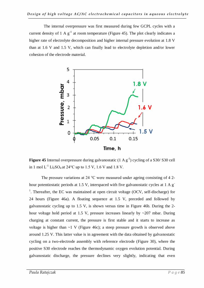
D e s i g n o f h i g h v o l t a g e A C / A C e l e c t r o c h e m i c a l c a p a c i t o r s i n a q u e o u s e l e c t r o l y t e
Paula Ratajczak P a g e 85
The internal overpressure was first measured during few GCPL cycles with a
current density of 1 A g-1
at room temperature (Figure 45). The plot clearly indicates a
higher rate of electrolyte decomposition and higher internal pressure evolution at 1.8 V
than at 1.6 V and 1.5 V, which can finally lead to electrolyte depletion and/or lower
cohesion of the electrode material.
Figure 45 Internal overpressure during galvanostatic (1 A g
-1) cycling of a S30/ S30 cell
in 1 mol L-1
Li2SO4 at 24°C up to 1.5 V, 1.6 V and 1.8 V.
The pressure variations at 24 °C were measured under ageing consisting of 4 2-
hour potentiostatic periods at 1.5 V, interspaced with five galvanostatic cycles at 1 A g-
1. Thereafter, the EC was maintained at open circuit voltage (OCV, self-discharge) for
24 hours (Figure 46a). A floating sequence at 1.5 V, preceded and followed by
galvanostatic cycling up to 1.5 V, is shown versus time in Figure 46b. During the 2-
hour voltage hold period at 1.5 V, pressure increases linearly by ~207 mbar. During
charging at constant current, the pressure is first stable and it starts to increase as
voltage is higher than ~1 V (Figure 46c); a steep pressure growth is observed above
around 1.25 V. This latter value is in agreement with the data obtained by galvanostatic
cycling on a two-electrode assembly with reference electrode (Figure 30), where the
positive S30 electrode reaches the thermodynamic oxygen evolution potential. During
galvanostatic discharge, the pressure declines very slightly, indicating that even

D e s i g n o f h i g h v o l t a g e A C / A C e l e c t r o c h e m i c a l c a p a c i t o r s i n a q u e o u s e l e c t r o l y t e
Paula Ratajczak P a g e 86
galvanostatic cycling at 1.5 V can reduce the lifetime on account of electrolyte depletion
and/or loss of electrode cohesion. Moreover, when considering the self-discharge at
OCV from 1.5 V (Figure 46a), the pressure slightly decreases. Such profile can be
assigned to very slow gas recombination into water and/or partial dissolution of gases in
the electrolyte [196, 197].
Figure 46 a) Internal overpressure evolution at 24 °C during full ageing protocol at 1.5
V on a S30/ S30 cell in 1 mol L-1
Li2SO4; (b) magnification of pressure evolution during
one 2-hour sequence preceded and followed by galvanostatic cycling at 1.5 V (1 A g-1
);
(c) magnification of pressure evolution during galvanostatic cycling (1 A g-1
) up to 1.5
V.
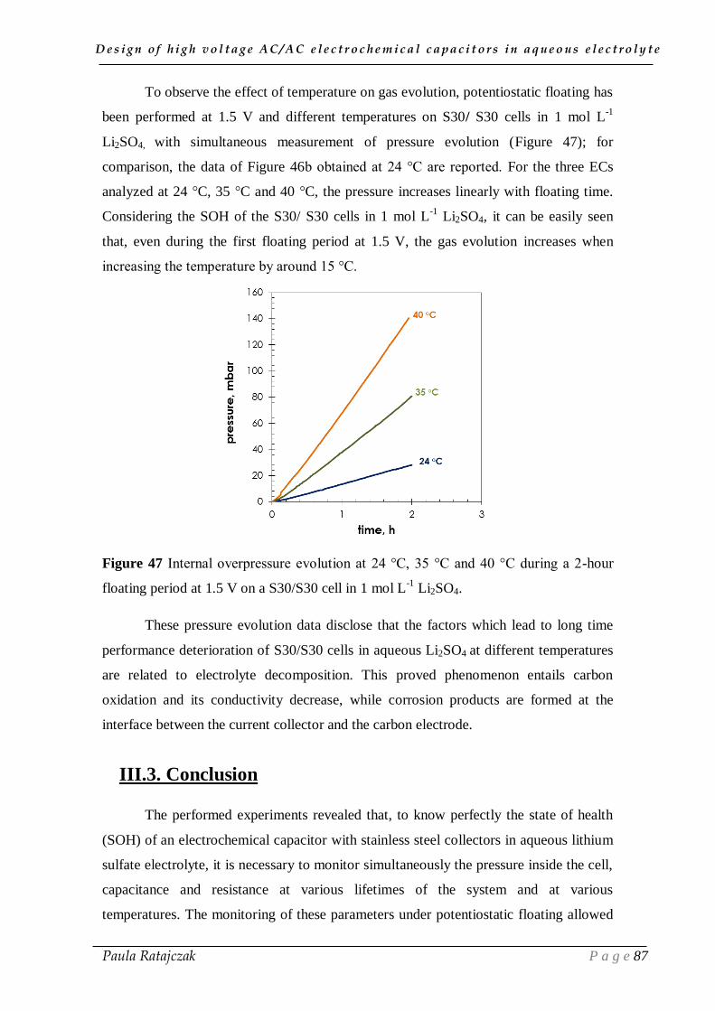
D e s i g n o f h i g h v o l t a g e A C / A C e l e c t r o c h e m i c a l c a p a c i t o r s i n a q u e o u s e l e c t r o l y t e
Paula Ratajczak P a g e 87
To observe the effect of temperature on gas evolution, potentiostatic floating has
been performed at 1.5 V and different temperatures on S30/ S30 cells in 1 mol L-1
Li2SO4, with simultaneous measurement of pressure evolution (Figure 47); for
comparison, the data of Figure 46b obtained at 24 °C are reported. For the three ECs
analyzed at 24 °C, 35 °C and 40 °C, the pressure increases linearly with floating time.
Considering the SOH of the S30/ S30 cells in 1 mol L-1
Li2SO4, it can be easily seen
that, even during the first floating period at 1.5 V, the gas evolution increases when
increasing the temperature by around 15 °C.
Figure 47 Internal overpressure evolution at 24 °C, 35 °C and 40 °C during a 2-hour
floating period at 1.5 V on a S30/S30 cell in 1 mol L-1
Li2SO4.
These pressure evolution data disclose that the factors which lead to long time
performance deterioration of S30/S30 cells in aqueous Li2SO4 at different temperatures
are related to electrolyte decomposition. This proved phenomenon entails carbon
oxidation and its conductivity decrease, while corrosion products are formed at the
interface between the current collector and the carbon electrode.
III.3. Conclusion
The performed experiments revealed that, to know perfectly the state of health
(SOH) of an electrochemical capacitor with stainless steel collectors in aqueous lithium
sulfate electrolyte, it is necessary to monitor simultaneously the pressure inside the cell,
capacitance and resistance at various lifetimes of the system and at various
temperatures. The monitoring of these parameters under potentiostatic floating allowed
D e s i g n o f h i g h v o l t a g e A C / A C e l e c t r o c h e m i c a l c a p a c i t o r s i n a q u e o u s e l e c t r o l y t e
Paula Ratajczak P a g e 88
to assess that ECs in 1 mol L-1
lithium sulfate electrolyte can operate with a very long
cycle life at voltage as high as 1.5 V at room temperature; such voltage is around 0.3–
0.4 V lower than the values mentioned in the literature when using gold current
collectors. Notwithstanding, the value of 1.5 V for the system in 1 mol L-1
Li2SO4 is
remarkably high when compared to 0.7–0.8 V for standard aqueous electrolytes (KOH
or H2SO4).
At voltage higher than 1.5 V, the decrease of capacitance during floating is
related to: (i) reduced accessible surface area due to oxidation of the carbon surface or
pore blockage by electrolyte decomposition or corrosion products; (ii) electrolyte
decomposition leading to ionic starvation in the electrode. The resistance increase under
accelerated ageing is generally due to: (i) electrolyte decomposition which leads to
deposition of corrosion products in the separator and on the positive electrode surface
(ionic contribution) and may be also caused by increased contact resistance between the
electrodes and current collectors (electronic contribution); (ii) gas products evolution
leading to weakening of the adhesion between the active mass and the current collector,
and also to the electronic contribution to contact resistance at the electrode/current
collectors interface.
Taking into account the results of this chapter, to improve the long time
performance of carbon-based electrochemical capacitors in neutral salt aqueous
electrolyte, strategies should be particularly intended to: (i) reduce the corrosion of
stainless steel collectors and decrease its destructive effect on ECs operation; (ii) and
avoid the decomposition of aqueous electrolyte through a shift of operating electrodes
potentials towards lower values. The results of these strategies will be presented in the
next chapter.
D e s i g n o f h i g h v o l t a g e A C / A C e l e c t r o c h e m i c a l c a p a c i t o r s i n a q u e o u s e l e c t r o l y t e
Paula Ratajczak P a g e 89
CHAPTER IV
STRATEGIES FOR IMPROVING
THE LONG TIME PERFORMANCE
OF HIGH VOLTAGE CAPACITORS
IN AQUEOUS ELECTROLYTES
D e s i g n o f h i g h v o l t a g e A C / A C e l e c t r o c h e m i c a l c a p a c i t o r s i n a q u e o u s e l e c t r o l y t e
Paula Ratajczak P a g e 90
The investigations performed in chapter III allowed disclosing the most
important factors contributing to ageing during high voltage operation of ECs based on
activated carbon electrodes and aqueous lithium sulfate electrolyte, which are: (i)
carbon oxidation reducing the accessible surface area, and/or electrolyte decomposition
leading to ionic starvation in the electrode [198], both causing a loss of capacitance; (ii)
formation of resistive decomposition products on the current collectors or gas products
evolution leading to weakening of the active mass adhesion on the current collector and
to increasing of resistance. Therefore, this chapter focuses on approaches intending to
cope with these possible perturbation phenomena which appear during high voltage
operation of ECs based on aqueous electrolytes. To eliminate or reduce the formation of
corrosion products at the interface between the AC electrode and the current collector,
three tactics have been particularly introduced: i) replacement of stainless steel current
collectors by nickel; ii) coating of the metallic foils with a conductive carbon layer; iii)
addition of sodium molybdate to the electrolytic solution to inhibit the corrosion of
steel. Finally, cells with asymmetric configuration of electrodes and coupled kinds of
current collectors have been used to avoid the decomposition of aqueous electrolyte
through down-shifting the operating electrodes potentials. The validity of the proposed
strategies was verified by electrochemical techniques, such as cyclic voltammetry and
impedance spectroscopy, as well as accelerated ageing by floating and monitoring of
internal pressure evolution.
IV.1. Corrosion reduction of positive current collector
In analogy to experiments presented in chapter III, a commercially available
carbon powder DLC Super 30 (Norit, S30) with a specific surface area of 1843 m2 g
-1
has been chosen as electrode active material for manufacturing pellet electrodes. The
electrodes were composed of 85 wt% S30, 10 wt% polyvinylidene fluoride as binder
(PVdF, Kynar HSV900, Arkema) and 5 wt% carbon black (C65, Timcal). To proceed in
the optimization of the system, coated electrodes (see paragraph 1.2.) were realized by
spreading the electrode material layer on the current collectors with an automatic
applicator using a Doctor blade. In this case, the electrode composition was 83.5 wt%
activated carbon YP80F (Kuraray Chemicals Co, YP80F), 8.5 wt% carbon black (C65,
Timcal) and 8 wt% polyvinylidene difluoride (PVdF, Kynar HSV 900, Arkema).
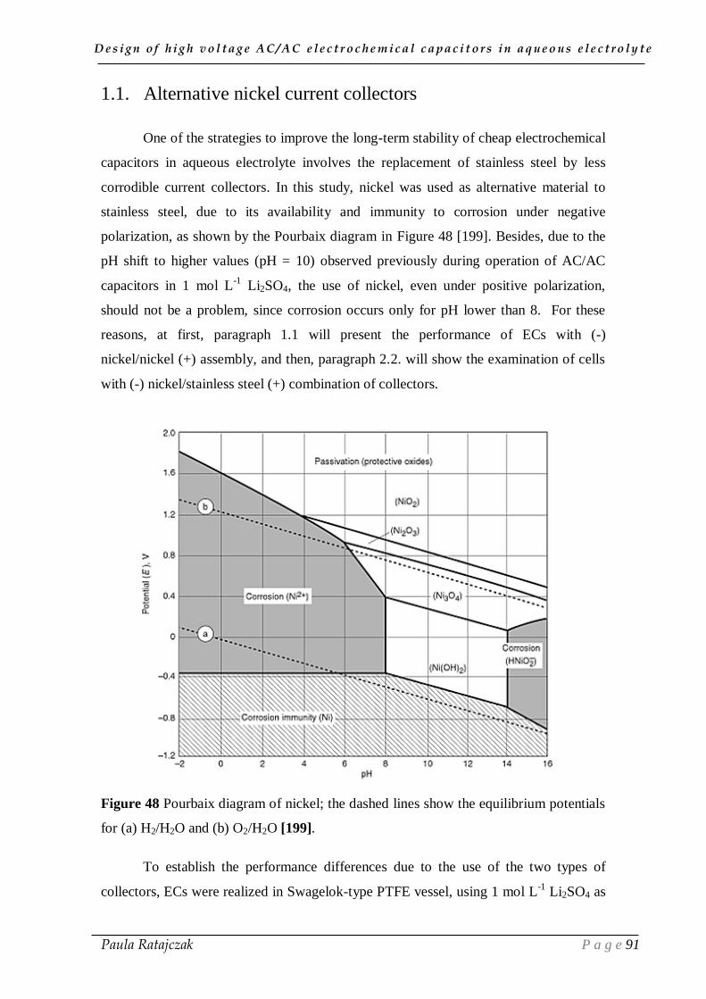
D e s i g n o f h i g h v o l t a g e A C / A C e l e c t r o c h e m i c a l c a p a c i t o r s i n a q u e o u s e l e c t r o l y t e
Paula Ratajczak P a g e 91
1.1. Alternative nickel current collectors
One of the strategies to improve the long-term stability of cheap electrochemical
capacitors in aqueous electrolyte involves the replacement of stainless steel by less
corrodible current collectors. In this study, nickel was used as alternative material to
stainless steel, due to its availability and immunity to corrosion under negative
polarization, as shown by the Pourbaix diagram in Figure 48 [199]. Besides, due to the
pH shift to higher values (pH = 10) observed previously during operation of AC/AC
capacitors in 1 mol L-1
Li2SO4, the use of nickel, even under positive polarization,
should not be a problem, since corrosion occurs only for pH lower than 8. For these
reasons, at first, paragraph 1.1 will present the performance of ECs with (-)
nickel/nickel (+) assembly, and then, paragraph 2.2. will show the examination of cells
with (-) nickel/stainless steel (+) combination of collectors.
Figure 48 Pourbaix diagram of nickel; the dashed lines show the equilibrium potentials
for (a) H2/H2O and (b) O2/H2O [199].
To establish the performance differences due to the use of the two types of
collectors, ECs were realized in Swagelok-type PTFE vessel, using 1 mol L-1
Li2SO4 as
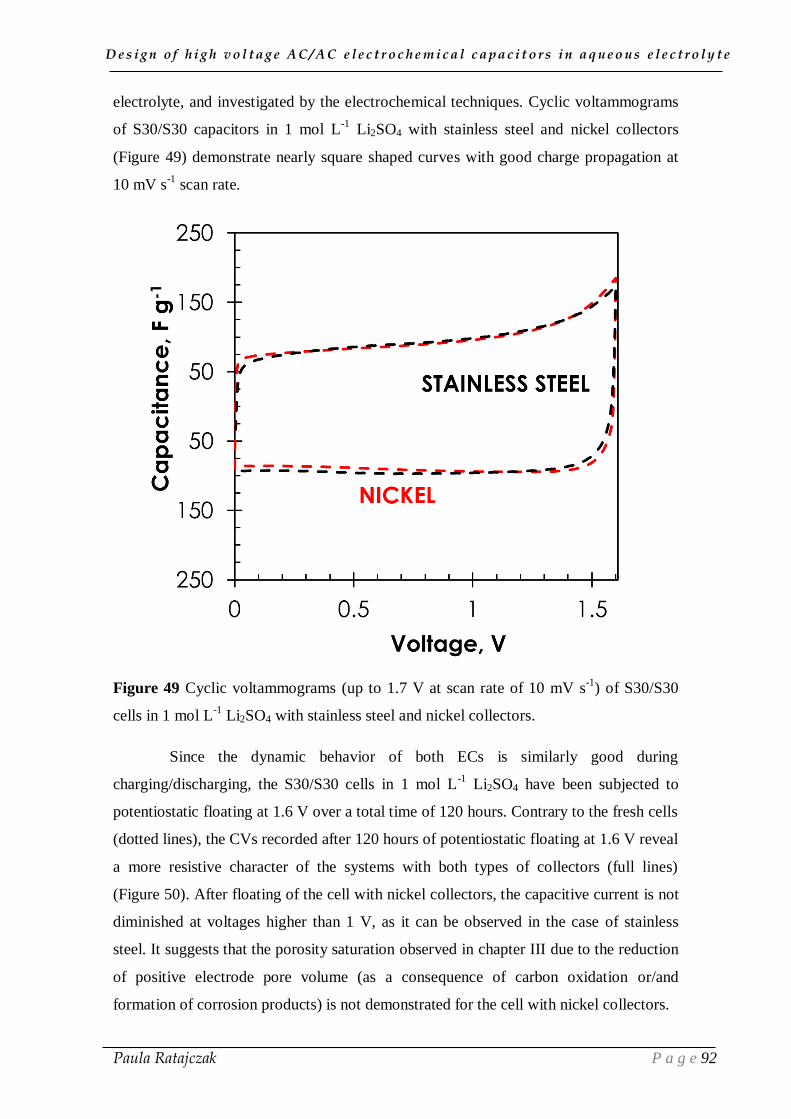
D e s i g n o f h i g h v o l t a g e A C / A C e l e c t r o c h e m i c a l c a p a c i t o r s i n a q u e o u s e l e c t r o l y t e
Paula Ratajczak P a g e 92
electrolyte, and investigated by the electrochemical techniques. Cyclic voltammograms
of S30/S30 capacitors in 1 mol L-1
Li2SO4 with stainless steel and nickel collectors
(Figure 49) demonstrate nearly square shaped curves with good charge propagation at
10 mV s-1
scan rate.
Figure 49 Cyclic voltammograms (up to 1.7 V at scan rate of 10 mV s-1
) of S30/S30
cells in 1 mol L-1
Li2SO4 with stainless steel and nickel collectors.
Since the dynamic behavior of both ECs is similarly good during
charging/discharging, the S30/S30 cells in 1 mol L-1
Li2SO4 have been subjected to
potentiostatic floating at 1.6 V over a total time of 120 hours. Contrary to the fresh cells
(dotted lines), the CVs recorded after 120 hours of potentiostatic floating at 1.6 V reveal
a more resistive character of the systems with both types of collectors (full lines)
(Figure 50). After floating of the cell with nickel collectors, the capacitive current is not
diminished at voltages higher than 1 V, as it can be observed in the case of stainless
steel. It suggests that the porosity saturation observed in chapter III due to the reduction
of positive electrode pore volume (as a consequence of carbon oxidation or/and
formation of corrosion products) is not demonstrated for the cell with nickel collectors.
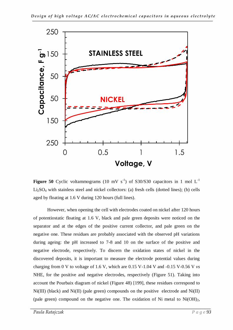
D e s i g n o f h i g h v o l t a g e A C / A C e l e c t r o c h e m i c a l c a p a c i t o r s i n a q u e o u s e l e c t r o l y t e
Paula Ratajczak P a g e 93
Figure 50 Cyclic voltammograms (10 mV s-1
) of S30/S30 capacitors in 1 mol L-1
Li2SO4 with stainless steel and nickel collectors: (a) fresh cells (dotted lines); (b) cells
aged by floating at 1.6 V during 120 hours (full lines).
However, when opening the cell with electrodes coated on nickel after 120 hours
of potentiostatic floating at 1.6 V, black and pale green deposits were noticed on the
separator and at the edges of the positive current collector, and pale green on the
negative one. These residues are probably associated with the observed pH variations
during ageing: the pH increased to 7-8 and 10 on the surface of the positive and
negative electrode, respectively. To discern the oxidation states of nickel in the
discovered deposits, it is important to measure the electrode potential values during
charging from 0 V to voltage of 1.6 V, which are 0.15 V-1.04 V and -0.15 V-0.56 V vs
NHE, for the positive and negative electrodes, respectively (Figure 51). Taking into
account the Pourbaix diagram of nickel (Figure 48) [199], these residues correspond to
Ni(III) (black) and Ni(II) (pale green) compounds on the positive electrode and Ni(II)
(pale green) compound on the negative one. The oxidation of Ni metal to Ni(OH)2,

D e s i g n o f h i g h v o l t a g e A C / A C e l e c t r o c h e m i c a l c a p a c i t o r s i n a q u e o u s e l e c t r o l y t e
Paula Ratajczak P a g e 94
appearing as a pale green residue on the edges of the positive electrode, is evidenced by
an increase of the anodic current at potential of 1.04 V vs NHE [200]. Afterwards, part
of the green Ni(II) can be oxidized to Ni(III) forming black Ni2O3 or NiOOH deposits
[201, 202].
Figure 51 CVs (5 mV s-1
) of individual electrodes of S30/S30 ECs in 1 mol L-1
Li2SO4
with nickel collectors, recorded up to voltage of 0.8 V, 1.0V, 1.2 V, 1.5 V, and 1.6 V;
the vertical dashed lines corresponds to the thermodynamic limits for water
decomposition.
Due to the good conductive properties of NiOOH, its presence will not much
impede the electrochemical performance of the EC. Figure 52 shows that, during
floating of the EC with nickel collectors at 1.6 V, the resistance remains stable till the
end of the test, suggesting that the performance of the cell is not affected by the
appearance of the residues. However, the exact nature of the deposits and their real
effect on the cells constituents during long time operation has not been yet investigated.
Notwithstanding, while the maximum voltage for long term operation of S30/S30 ECs
with stainless steel collectors under floating is 1.5 V (chapter III), the S30/S30 system
with nickel collectors can operate up to 1.6 V without deterioration of the
electrochemical performance after 120 hours of accelerated ageing (Figure 52).
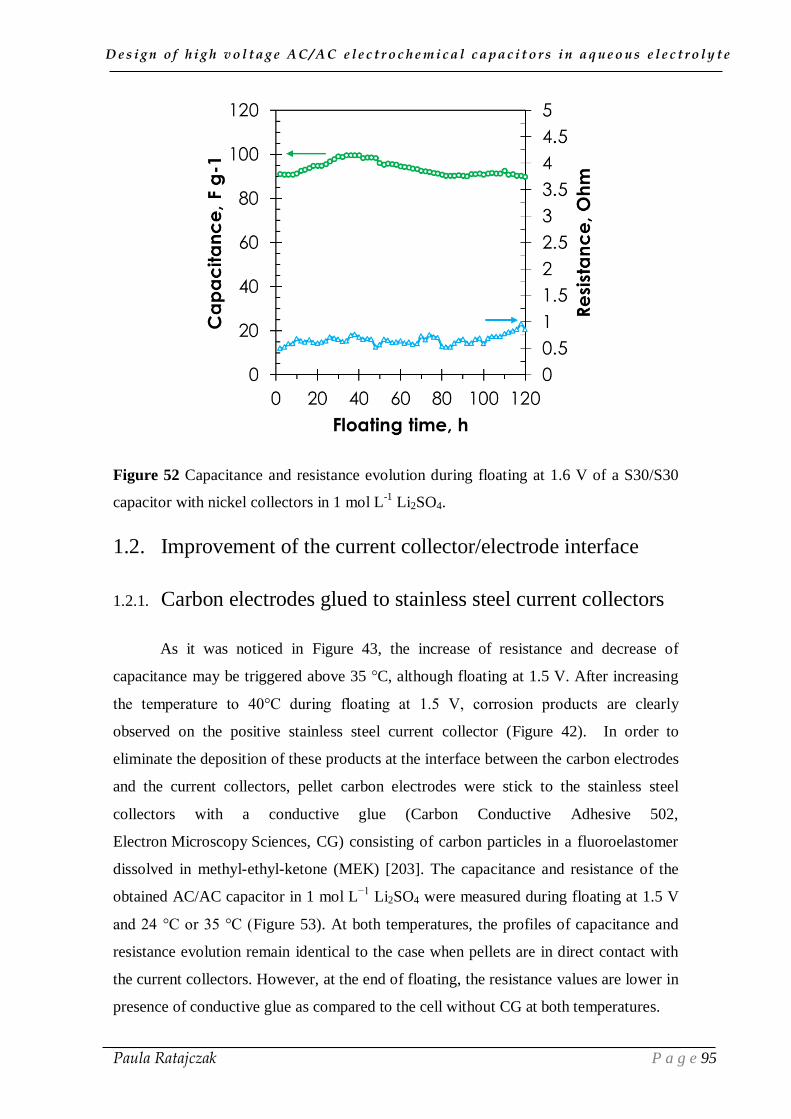
D e s i g n o f h i g h v o l t a g e A C / A C e l e c t r o c h e m i c a l c a p a c i t o r s i n a q u e o u s e l e c t r o l y t e
Paula Ratajczak P a g e 95
Figure 52 Capacitance and resistance evolution during floating at 1.6 V of a S30/S30
capacitor with nickel collectors in 1 mol L-1
Li2SO4.
1.2. Improvement of the current collector/electrode interface
1.2.1. Carbon electrodes glued to stainless steel current collectors
As it was noticed in Figure 43, the increase of resistance and decrease of
capacitance may be triggered above 35 °C, although floating at 1.5 V. After increasing
the temperature to 40°C during floating at 1.5 V, corrosion products are clearly
observed on the positive stainless steel current collector (Figure 42). In order to
eliminate the deposition of these products at the interface between the carbon electrodes
and the current collectors, pellet carbon electrodes were stick to the stainless steel
collectors with a conductive glue (Carbon Conductive Adhesive 502,
Electron Microscopy Sciences, CG) consisting of carbon particles in a fluoroelastomer
dissolved in methyl-ethyl-ketone (MEK) [203]. The capacitance and resistance of the
obtained AC/AC capacitor in 1 mol L−1
Li2SO4 were measured during floating at 1.5 V
and 24 °C or 35 °C (Figure 53). At both temperatures, the profiles of capacitance and
resistance evolution remain identical to the case when pellets are in direct contact with
the current collectors. However, at the end of floating, the resistance values are lower in
presence of conductive glue as compared to the cell without CG at both temperatures.
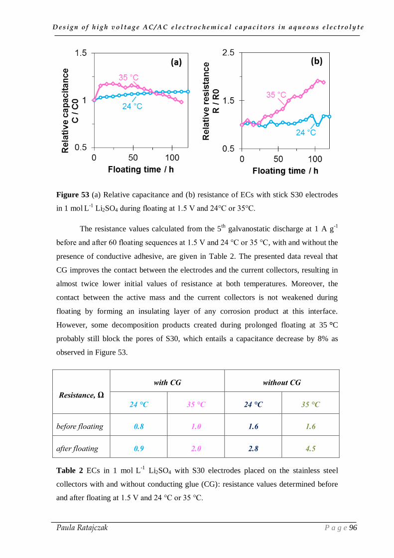
D e s i g n o f h i g h v o l t a g e A C / A C e l e c t r o c h e m i c a l c a p a c i t o r s i n a q u e o u s e l e c t r o l y t e
Paula Ratajczak P a g e 96
Figure 53 (a) Relative capacitance and (b) resistance of ECs with stick S30 electrodes
in 1 mol L
-1 Li2SO4 during floating at 1.5 V and 24°C or 35°C.
The resistance values calculated from the 5th
galvanostatic discharge at 1 A g-1
before and after 60 floating sequences at 1.5 V and 24 °C or 35 °C, with and without the
presence of conductive adhesive, are given in Table 2. The presented data reveal that
CG improves the contact between the electrodes and the current collectors, resulting in
almost twice lower initial values of resistance at both temperatures. Moreover, the
contact between the active mass and the current collectors is not weakened during
floating by forming an insulating layer of any corrosion product at this interface.
However, some decomposition products created during prolonged floating at 35 °C
probably still block the pores of S30, which entails a capacitance decrease by 8% as
observed in Figure 53.
Resistance, Ω
with CG without CG
24 °C 35 °C 24 °C 35 °C
before floating 0.8 1.0 1.6 1.6
after floating 0.9 2.0 2.8 4.5
Table 2 ECs in 1 mol L
-1 Li2SO4 with S30 electrodes placed on the stainless steel
collectors with and without conducting glue (CG): resistance values determined before
and after floating at 1.5 V and 24 °C or 35 °C.

D e s i g n o f h i g h v o l t a g e A C / A C e l e c t r o c h e m i c a l c a p a c i t o r s i n a q u e o u s e l e c t r o l y t e
Paula Ratajczak P a g e 97
1.2.2. Nickel foil substrate
Since some improvement was given by the use of conducting glue, and to
proceed further in the optimization of the system, we decided to follow the industrial
way of electrodes realization, where the active material layer is spread on the current
collectors with an applicator using a Doctor Blade. Moreover, since stable resistance
and capacitance was observed during ageing the EC with nickel collectors at 1.6 V
(Figure 52), we decided to use nickel foil (200/201 grade, Schlenk, thickness = 20 μm)
as substrate to prepare the coated electrodes. For this study, the commercially available
carbon YP80F (Kuraray Co.) with a high specific surface area of 2270 m2 g
-1 and
L0=1.05 nm has been chosen as electrode active material (see experimental annex
A.1.1).
Unfortunately, accelerated ageing at 1.5 V and 24 °C revealed an insufficient
contact between the nickel foil substrate and the electrode material, which peeled off
from the foil during ageing. In the literature concerning EDLCs in aqueous electrolyte,
it has been demonstrated that the performance, especially the contact resistance, is
dramatically improved by etching the current collector in order to better anchor the
coating layer [204].
Figure 54 Scanning electron microscopy (SEM) images of (a, c) nickel foil 200/201,
and (b, d) soft-annealed nickel foil current collectors.
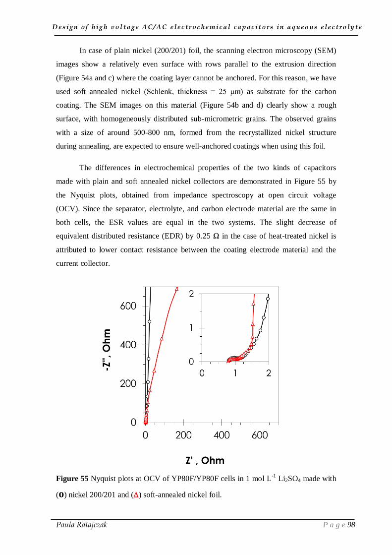
D e s i g n o f h i g h v o l t a g e A C / A C e l e c t r o c h e m i c a l c a p a c i t o r s i n a q u e o u s e l e c t r o l y t e
Paula Ratajczak P a g e 98
In case of plain nickel (200/201) foil, the scanning electron microscopy (SEM)
images show a relatively even surface with rows parallel to the extrusion direction
(Figure 54a and c) where the coating layer cannot be anchored. For this reason, we have
used soft annealed nickel (Schlenk, thickness = 25 μm) as substrate for the carbon
coating. The SEM images on this material (Figure 54b and d) clearly show a rough
surface, with homogeneously distributed sub-micrometric grains. The observed grains
with a size of around 500-800 nm, formed from the recrystallized nickel structure
during annealing, are expected to ensure well-anchored coatings when using this foil.
The differences in electrochemical properties of the two kinds of capacitors
made with plain and soft annealed nickel collectors are demonstrated in Figure 55 by
the Nyquist plots, obtained from impedance spectroscopy at open circuit voltage
(OCV). Since the separator, electrolyte, and carbon electrode material are the same in
both cells, the ESR values are equal in the two systems. The slight decrease of
equivalent distributed resistance (EDR) by 0.25 Ω in the case of heat-treated nickel is
attributed to lower contact resistance between the coating electrode material and the
current collector.
Figure 55 Nyquist plots at OCV of YP80F/YP80F cells in 1 mol L-1
Li2SO4 made with
(o) nickel 200/201 and () soft-annealed nickel foil.
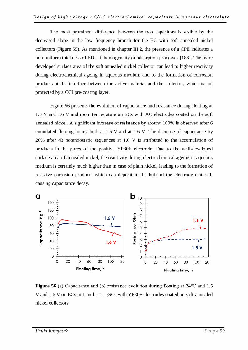
D e s i g n o f h i g h v o l t a g e A C / A C e l e c t r o c h e m i c a l c a p a c i t o r s i n a q u e o u s e l e c t r o l y t e
Paula Ratajczak P a g e 99
The most prominent difference between the two capacitors is visible by the
decreased slope in the low frequency branch for the EC with soft annealed nickel
collectors (Figure 55). As mentioned in chapter III.2, the presence of a CPE indicates a
non-uniform thickness of EDL, inhomogeneity or adsorption processes [186]. The more
developed surface area of the soft annealed nickel collector can lead to higher reactivity
during electrochemical ageing in aqueous medium and to the formation of corrosion
products at the interface between the active material and the collector, which is not
protected by a CCI pre-coating layer.
Figure 56 presents the evolution of capacitance and resistance during floating at
1.5 V and 1.6 V and room temperature on ECs with AC electrodes coated on the soft
annealed nickel. A significant increase of resistance by around 100% is observed after 6
cumulated floating hours, both at 1.5 V and at 1.6 V. The decrease of capacitance by
20% after 43 potentiostatic sequences at 1.6 V is attributed to the accumulation of
products in the pores of the positive YP80F electrode. Due to the well-developed
surface area of annealed nickel, the reactivity during electrochemical ageing in aqueous
medium is certainly much higher than in case of plain nickel, leading to the formation of
resistive corrosion products which can deposit in the bulk of the electrode material,
causing capacitance decay.
Figure 56 (a) Capacitance and (b) resistance evolution during floating at 24°C and 1.5
V and 1.6 V on ECs in 1 mol L
-1 Li2SO4 with YP80F electrodes coated on soft-annealed
nickel collectors.
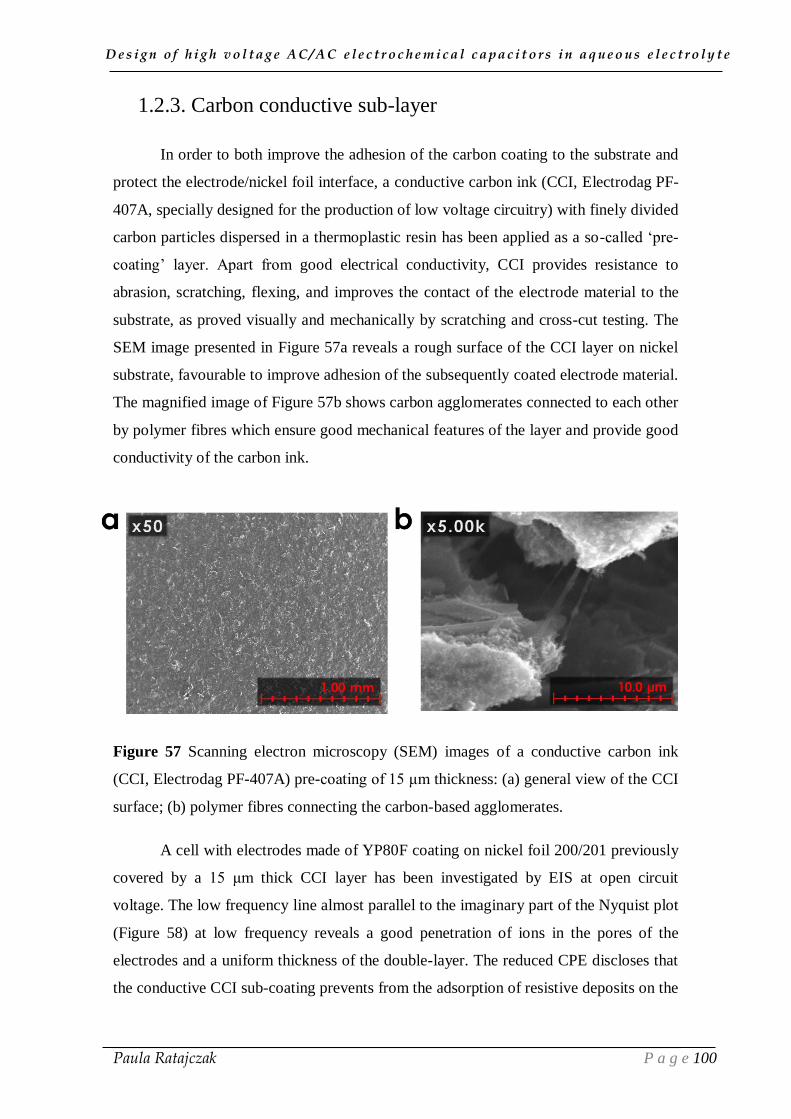
D e s i g n o f h i g h v o l t a g e A C / A C e l e c t r o c h e m i c a l c a p a c i t o r s i n a q u e o u s e l e c t r o l y t e
Paula Ratajczak P a g e 100
1.2.3. Carbon conductive sub-layer
In order to both improve the adhesion of the carbon coating to the substrate and
protect the electrode/nickel foil interface, a conductive carbon ink (CCI, Electrodag PF-
407A, specially designed for the production of low voltage circuitry) with finely divided
carbon particles dispersed in a thermoplastic resin has been applied as a so-called ‘pre-
coating’ layer. Apart from good electrical conductivity, CCI provides resistance to
abrasion, scratching, flexing, and improves the contact of the electrode material to the
substrate, as proved visually and mechanically by scratching and cross-cut testing. The
SEM image presented in Figure 57a reveals a rough surface of the CCI layer on nickel
substrate, favourable to improve adhesion of the subsequently coated electrode material.
The magnified image of Figure 57b shows carbon agglomerates connected to each other
by polymer fibres which ensure good mechanical features of the layer and provide good
conductivity of the carbon ink.
Figure 57 Scanning electron microscopy (SEM) images of a conductive carbon ink
(CCI, Electrodag PF-407A) pre-coating of 15 μm thickness: (a) general view of the CCI
surface; (b) polymer fibres connecting the carbon-based agglomerates.
A cell with electrodes made of YP80F coating on nickel foil 200/201 previously
covered by a 15 μm thick CCI layer has been investigated by EIS at open circuit
voltage. The low frequency line almost parallel to the imaginary part of the Nyquist plot
(Figure 58) at low frequency reveals a good penetration of ions in the pores of the
electrodes and a uniform thickness of the double-layer. The reduced CPE discloses that
the conductive CCI sub-coating prevents from the adsorption of resistive deposits on the

D e s i g n o f h i g h v o l t a g e A C / A C e l e c t r o c h e m i c a l c a p a c i t o r s i n a q u e o u s e l e c t r o l y t e
Paula Ratajczak P a g e 101
surface of nickel. As compared to the cell with the same nickel 200/201 substrate
without CCI, the increase of low frequency branch slope results from the decrease of
equivalent distributed resistance (EDR) (Figure 58 and Table 3).
Figure 58 Nyquist plot at OCV of a YP80F/YP80F cell in 1 mol L-1
Li2SO4 made with
nickel 200/201 collectors with () and without (o) CCI pre-coating.
Since the path of ions to the active surface area is the same in both cells with and
without CCI pre-coating, they display almost identical ESR values (Table 3).
Notwithstanding, the current is distributed more evenly when the electrode coating is
anchored to the substrate with help of the conductive ink. The charge transfer resistance
value Rf, (responsible for the radius of the high-frequency semi-circle), is a bit lower for
the cell with pre-coating as compared to the cell with plain nickel collectors.
In conclusion, anchoring of coating is improved in fresh cells either by CCI pre-
coating of plain nickel or by use of annealed nickel. However, one should not forget
that floating tests have revealed a high surface reactivity of annealed nickel, and
demonstrated its incompatibility with lithium sulfate electrolyte. Therefore,
potentiostatic floating is necessary to validate the improvement observed on the fresh
cells using CCI pre-coated nickel collectors.

D e s i g n o f h i g h v o l t a g e A C / A C e l e c t r o c h e m i c a l c a p a c i t o r s i n a q u e o u s e l e c t r o l y t e
Paula Ratajczak P a g e 102
Nickel 200/201 Pre-coated
nickel 200/201
ESR 0.77 0.76
EDR 1.78 1.27
Rf 0.41 0.38
Table 3 ESR, EDR and Rf values obtained from the Nyquist plots of YP80F/YP80F
capacitors in 1 mol L-1
Li2SO4 made with nickel 200/201, with and without CCI pre-
coating.
Figure 59 shows the evolution of relative capacitance and resistance during
potentiostatic floating at 1.5 V and 1.6 V on YP-80F/YP-80F cells in 1 mol L-1
Li2SO4
with electrodes coated on nickel pre-coated by CCI. Definitely, the comparison with
Figure 56 reveals a dramatic improvement in stability of electrochemical performance;
after 120 cumulated hours of floating at 1.5 V or 1.6 V, the values of resistance and
capacitance are almost identical to the initial values. As for the previously examined
ECs without CCI, the more pronounced initial capacitance increase for the cell
examined at 1.6 V is the most probably attributed to a better penetration of ions in the
porosity of electrodes (Figure 59a); nonetheless, further floating series do not influence
ageing of the cell.
Figure 59 (a) Capacitance and (b) resistance evolution of YP80F/YP80F cell in 1 mol
L-1
Li2SO4 made with pre-coated nickel foil with CCI during floating at 24°C and 1.5 V
and 1.6 V.
D e s i g n o f h i g h v o l t a g e A C / A C e l e c t r o c h e m i c a l c a p a c i t o r s i n a q u e o u s e l e c t r o l y t e
Paula Ratajczak P a g e 103
Stable C/C0 profile suggests that neither any decomposition products block the
carbon active surface, nor the good contact between the electrodes and the current
collectors is disturbed. This statement is supported by the resistance evolution presented
in Figure 59b, which values are maintained below 1 Ω during the whole 60 series both
at 1.5 V and at 1.6 V. Besides, after opening the cell, the AC electrodes were still well
attached to the nickel foils pre-coated with the conductive ink.
Hence, the floating tests reveal the necessity of conductive pre-coatings in the
manufacturing of carbon electrodes, in order to ensure satisfactory long-term
performance of high voltage electrochemical capacitors in neutral aqueous electrolytes.
To sum up, when nickel collectors are used with self-standing S30 electrodes (part 1.1),
as well as with YP-80F electrodes coated on CCI/nickel substrate (part 1.2), ECs in 1
mol L-1
Li2SO4 can operate up to 1.6 V without deterioration of electrochemical
performance.
1.3. Addition of corrosion inhibitor
According to the investigations performed by Q. Abbas in our research group,
sodium molybdate (Na2MoO4) as additive to lithium sulfate electrolyte reduces the
corrosion of current collectors in AC/AC capacitors, whereas the capacitance is
enhanced through faradaic contributions [205]. Therefore, we have prolonged this
research on lifetime improvement, by investigating the performance of S30/S30 cells
with 0.1 mol L-1
Na2MoO4 + 1 mol L-1
Li2SO4 electrolyte at 24 °C and 40 °C.
Cyclic voltammograms of the capacitors with S30 electrodes in the form of
pellets in 1 mol L-1
Li2SO4 (pH = 6.5, conductivity = 64 mS cm-1
) and 1 mol L-1
Li2SO4
+ 0.1 mol L-1
Na2MoO4 (pH = 6.7, conductivity = 72 mS cm-1
) performed at 10 mV s-1
scan rate up to 1.5 V are presented in Figure 60. Due to redox processes involving the
molybdate ions, the capacitance is higher in Li2SO4 + Na2MoO4 than in Li2SO4. This
enhancement of capacitive current, as well as more rectangular shape of the CV curve
for EC with Li2SO4 + Na2MoO4, as compared to the one with Li2SO4, could be also
partly attributed to the higher conductivity of the electrolyte with the molybdate
additive.

D e s i g n o f h i g h v o l t a g e A C / A C e l e c t r o c h e m i c a l c a p a c i t o r s i n a q u e o u s e l e c t r o l y t e
Paula Ratajczak P a g e 104
Figure 60 Cyclic voltammograms (10 mV s-1
) of S30/S30 capacitors in 1 mol L-1
Li2SO4 and 1 mol L-1
Li2SO4 + 0.1 mol L-1
Na2MoO4 electrolytes up to 1.5 V.
To determine the impact of the molybdate additive on ageing, ECs in 1 mol L-1
Li2SO4 + 0.1 mol L-1
Na2MoO4 were submitted to floating at 1.5 V at 24 °C or 40 °C
with simultaneous monitoring of cell capacitance and resistance (Figure 61). As for the
previously presented capacitors in Li2SO4 (Figure 43), capacitance of ECs with Li2SO4
+ Na2MoO4 increases during the first 20 floating hours. However, when the floating is
prolonged, the capacitance remains almost constant, while it decreased for the capacitor
in 1 mol L-1
Li2SO4 at 40°C.
Figure 61 Effect of floating at 1.5 V and 24°C or 40°C on the evolution of (a) specific
capacitance and (b) relative resistance of a S30/S30 capacitor in 1 mol L
-1 Li2SO4 + 0.1
mol L
-1 Na2MoO4.
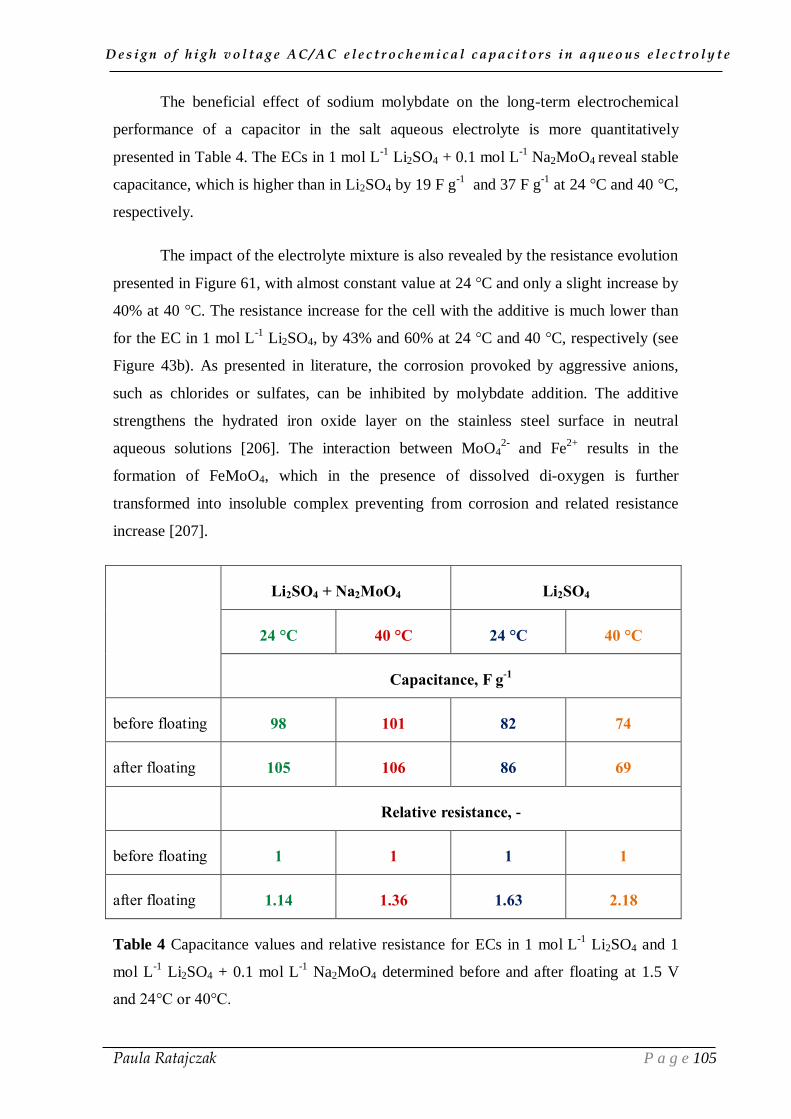
D e s i g n o f h i g h v o l t a g e A C / A C e l e c t r o c h e m i c a l c a p a c i t o r s i n a q u e o u s e l e c t r o l y t e
Paula Ratajczak P a g e 105
The beneficial effect of sodium molybdate on the long-term electrochemical
performance of a capacitor in the salt aqueous electrolyte is more quantitatively
presented in Table 4. The ECs in 1 mol L-1
Li2SO4 + 0.1 mol L-1
Na2MoO4 reveal stable
capacitance, which is higher than in Li2SO4 by 19 F g-1
and 37 F g-1
at 24 °C and 40 °C,
respectively.
The impact of the electrolyte mixture is also revealed by the resistance evolution
presented in Figure 61, with almost constant value at 24 °C and only a slight increase by
40% at 40 °C. The resistance increase for the cell with the additive is much lower than
for the EC in 1 mol L-1
Li2SO4, by 43% and 60% at 24 °C and 40 °C, respectively (see
Figure 43b). As presented in literature, the corrosion provoked by aggressive anions,
such as chlorides or sulfates, can be inhibited by molybdate addition. The additive
strengthens the hydrated iron oxide layer on the stainless steel surface in neutral
aqueous solutions [206]. The interaction between MoO42-
and Fe2+
results in the
formation of FeMoO4, which in the presence of dissolved di-oxygen is further
transformed into insoluble complex preventing from corrosion and related resistance
increase [207].
Li2SO4 + Na2MoO4 Li2SO4
24 °C 40 °C 24 °C 40 °C
Capacitance, F g-1
before floating 98 101 82 74
after floating 105 106 86 69
Relative resistance, -
before floating 1 1 1 1
after floating 1.14 1.36 1.63 2.18
Table 4 Capacitance values and relative resistance for ECs in 1 mol L
-1 Li2SO4 and 1
mol L-1
Li2SO4 + 0.1 mol L-1
Na2MoO4 determined before and after floating at 1.5 V
and 24°C or 40°C.

D e s i g n o f h i g h v o l t a g e A C / A C e l e c t r o c h e m i c a l c a p a c i t o r s i n a q u e o u s e l e c t r o l y t e
Paula Ratajczak P a g e 106
In Figure 62 showing the aspect of the stainless steel current collectors after
floating at 1.5 V and 40°C in 1 mol L-1
Li2SO4 + 0.1 mol L-1
Na2MoO4, a grey deposit is
apparent essentially on the positive current collector and separator. According to the
Pourbaix diagram of molybdenum [199], the reaction (39) occurs at neutral pH of the
electrolyte:
MoO2 + 2H2O → MoO42-
+ 4H+ + 2e
- (39)
Therefore, the deposit on the positive electrode is probably assigned to a protective
passive film, composed mainly of MoO42−
, MoO2 and some traces of MoO3. The
transformation of molybdate ions into HMoO4- and further into MoO3 can originate
from water oxidation at the positive electrode, which contributes to a locally decreased
pH and shift of equilibrium potentials [199].
Figure 62 Collectors and separator of a S30/S30 cell after 120 hours of floating at 1.5 V
and 40°C in 1 mol L-1
Li2SO4 + 0.1 mol L-1
Na2MoO4.

D e s i g n o f h i g h v o l t a g e A C / A C e l e c t r o c h e m i c a l c a p a c i t o r s i n a q u e o u s e l e c t r o l y t e
Paula Ratajczak P a g e 107
Beside the faradaic contribution and inhibition of corrosion, the presence of
sodium molybdate in neutral aqueous electrolyte is supposed to reduce also another
important factor contributing to ageing of the system at high voltage, namely electrolyte
oxidation. Indeed, the investigations on two-electrode S30/S30 cell equipped with a
reference electrode presented by Abbas et al. [205] showed that the potential reached by
the positive electrode (E+) in presence of Li2SO4 + Na2MoO4 electrolyte is shifted by
around -0.162 V as compared to Li2SO4. For this reason, whilst in the cell with lithium
sulfate electrolyte, the potential of the positive electrode reaches the thermodynamic
oxygen evolution limit of 0.84 V vs NHE at voltage of only 1.35 V, the system with
sodium molybdate additive can operate at room temperature up to 1.6 V with positive
electrode potential 0.042 V below the thermodynamic oxygen evolution potential. In
conclusion from the referred study [205], the shift of potentials toward negative values
should practically prevent from electrolyte decomposition and positive stainless steel
current collector corrosion during ageing at 1.5 V.
To verify the above statement, the evolving rate of gases during one 2-hour
floating period at 1.5 V at room temperature (24 °C) and at 40 °C was measured with a
pressure sensor connected to the electrochemical cells with Li2SO4 and Li2SO4 +
Na2MoO4 (see Figure 44 for the system construction), and the results are shown in
Figure 63. Considering the experiments performed at 24 °C, the addition of molybdate
to the electrolyte dramatically reduces the internal pressure increase by ~25 mbar. At
higher temperature of 40°C, the impact of the additive is less significant, and the
pressure increases in both cells (with and without molybdate) by 130 mbar and 140
mbar, respectively. This diminished effect of the corrosion inhibitor to reduce gases
evolution can be attributed to the inactivity of MoO42-
to form molybdenum complexes
at 40 °C. The curves presented in Figure 63 exhibit a linear pressure growth,
demonstrating the destructive effect of ageing at higher temperatures, which occurs just
from the beginning of floating. Consequently, the increase of resistance displayed
during prolonged potentiostatic voltage hold at 40°C in Figure 61b seems to be
essentially related to the evolution of gases which might worsen the electrical contacts
between electrodes and current collectors.

D e s i g n o f h i g h v o l t a g e A C / A C e l e c t r o c h e m i c a l c a p a c i t o r s i n a q u e o u s e l e c t r o l y t e
Paula Ratajczak P a g e 108
Figure 63 Internal overpressure evolution in S30/S30 cells with and without sodium
molybdate additive during two hours potentiostatic floating at 1.5 V and 24 ⁰C or 40 ⁰C.
As observed in chapter III.3, the increase of resistance during floating, as well as
pressure evolution, due to electrolyte decomposition, suggest a possible oxidation of the
positive carbon electrode. Figure 64 presents the mass loss, and CO2 and CO profiles
obtained by TPD for the fresh ACC and the positive and negative ACC electrodes of an
EC in 1 mol L-1
Li2SO4 + 0.1 mol L-1
Na2MoO4 electrolyte aged by 120 floating hours at
1.7 V and RT. The data also reveal surface oxidation of carbon electrodes as compared
to the case of the cell without molybdate addition (Figure 39). The mass loss at 950 °C
is 44.8 % for the positive and 18.5 % for the negative electrode, as compared to 43.6%
and 14.5%, respectively, for the EC in 1 mol L-1
Li2SO4. However, the surface
functionality of the positive and negative aged electrodes is different. It is rich in new
oxygenated groups, releasing 4.8 mmol g-1
and 1.2 mmol g-1
of CO2, respectively. The
cumulated released CO is 6.8 mmol g-1
and 4.9 mmol g-1
, for the positive and negative
electrode, respectively, which is actually few times more than for the ACC electrodes
operating in Li2SO4. During floating in presence of molybdate ions, the carbon surface
is oxidized with formation of new CO-evolving groups identified as carbonyl/quinone
groups and pyrone-type structures at 820 °C and 940 °C, respectively [193, 194].
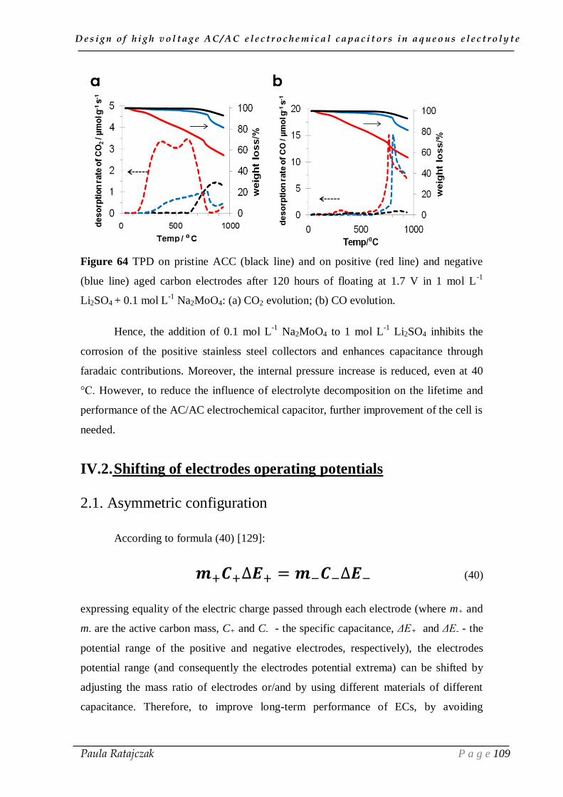
D e s i g n o f h i g h v o l t a g e A C / A C e l e c t r o c h e m i c a l c a p a c i t o r s i n a q u e o u s e l e c t r o l y t e
Paula Ratajczak P a g e 109
Figure 64 TPD on pristine ACC (black line) and on positive (red line) and negative
(blue line) aged carbon electrodes after 120 hours of floating at 1.7 V in 1 mol L-1
Li2SO4 + 0.1 mol L-1
Na2MoO4: (a) CO2 evolution; (b) CO evolution.
Hence, the addition of 0.1 mol L-1
Na2MoO4 to 1 mol L-1
Li2SO4 inhibits the
corrosion of the positive stainless steel collectors and enhances capacitance through
faradaic contributions. Moreover, the internal pressure increase is reduced, even at 40
°C. However, to reduce the influence of electrolyte decomposition on the lifetime and
performance of the AC/AC electrochemical capacitor, further improvement of the cell is
needed.
IV.2. Shifting of electrodes operating potentials
2.1. Asymmetric configuration
According to formula (40) [129]:
𝒎+𝑪+∆𝑬+ = 𝒎−𝑪−∆𝑬− (40)
expressing equality of the electric charge passed through each electrode (where m+ and
m- are the active carbon mass, C+ and C- - the specific capacitance, ΔE+ and ΔE- - the
potential range of the positive and negative electrodes, respectively), the electrodes
potential range (and consequently the electrodes potential extrema) can be shifted by
adjusting the mass ratio of electrodes or/and by using different materials of different
capacitance. Therefore, to improve long-term performance of ECs, by avoiding

D e s i g n o f h i g h v o l t a g e A C / A C e l e c t r o c h e m i c a l c a p a c i t o r s i n a q u e o u s e l e c t r o l y t e
Paula Ratajczak P a g e 110
decomposition of electrolyte, electrochemical capacitors with asymmetric configuration
of electrodes with different carbons in 1 mol L-1
Li2SO4 were built. Such effect of
shifting electrodes operating potential has been previously observed with (-) AC /MnO2
(+) capacitors in 0.5 mol L−1
Na2SO4 using a mass ratio m+/m- = 2.5 and voltage of 2 V
[208]. Although the short time experiments in two-electrode cell with reference
electrode showed the possibility to reach 2.2 V with the latter system, galvanostatic
cycling revealed that the maximum voltage for this system needs to be reduced by 0.2 V
for a good cycle life. Therefore, in the present study, after the basic electrochemical
investigations on the realized asymmetric carbon/carbon cells, both the SOH of ECs and
the actual values of potentials reached by the positive and negative electrode have been
simultaneous monitored during accelerated ageing by floating at 1.5 V.
Taking into account equation (40), our objective has been to realize a capacitor
with electrodes of same mass of two carbons with different capacitance. The cyclic
voltammograms of two symmetric cells built with the S30 and Burley800 (SBET = 1651
m2 g
-1; L0 = 0.86 nm) [78] (further named as B800) carbons in 1 mol L
-1 Li2SO4
demonstrate higher capacitance for B800 (Figure 65); from galvanostatic
charge/discharge measurements, the capacitance values are 82 F g-1
and 125 F g-1
for
S30 and B800, respectively. Therefore, an asymmetric capacitor has been built with
B800 as positive electrode and S30 as negative one, in order to get ΔE->ΔE+ and
consequently to shift the potential extrema of electrodes towards lower values.
Figure 65 Cyclic voltammograms at 10 mV s-1
for symmetric cells based on the S30
and B800 carbons in 1 mol L-1
Li2SO4.
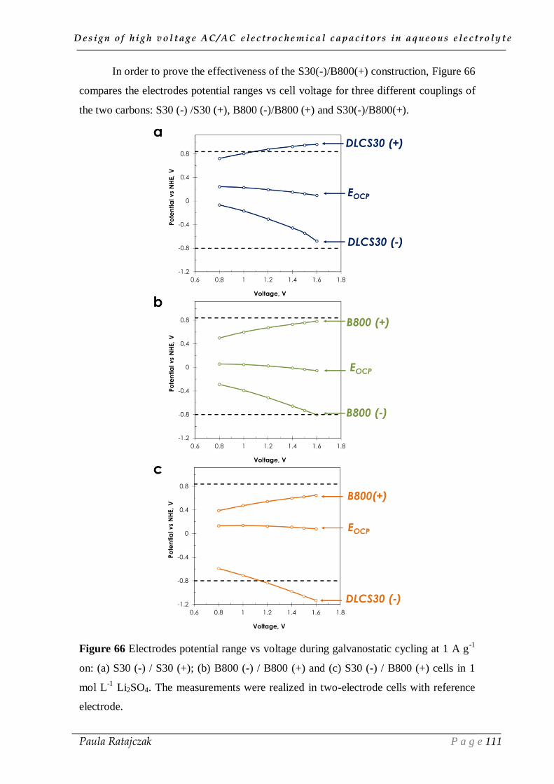
D e s i g n o f h i g h v o l t a g e A C / A C e l e c t r o c h e m i c a l c a p a c i t o r s i n a q u e o u s e l e c t r o l y t e
Paula Ratajczak P a g e 111
In order to prove the effectiveness of the S30(-)/B800(+) construction, Figure 66
compares the electrodes potential ranges vs cell voltage for three different couplings of
the two carbons: S30 (-) /S30 (+), B800 (-)/B800 (+) and S30(-)/B800(+).
Figure 66 Electrodes potential range vs voltage during galvanostatic cycling at 1 A g-1
on: (a) S30 (-) / S30 (+); (b) B800 (-) / B800 (+) and (c) S30 (-) / B800 (+) cells in 1
mol L-1
Li2SO4. The measurements were realized in two-electrode cells with reference
electrode.

D e s i g n o f h i g h v o l t a g e A C / A C e l e c t r o c h e m i c a l c a p a c i t o r s i n a q u e o u s e l e c t r o l y t e
Paula Ratajczak P a g e 112
For the two symmetric systems in 1 mol L-1
Li2SO4, lower value of positive
electrode potential is reached at voltage of 1.6 V with B800 (-) /B800 (+) (Figure 66b)
as compared to S30 (-) /S30 (+) (Figure 66a) , 0.78 V and 0.96 V, respectively. Due to
the higher capacitance of the B800 carbon as compared to S30, the shift of positive
electrode potential is more pronounced for the S30 (-) /B800 (+) asymmetric
configuration (Figure 66c). Taking into account the limit for water reduction and
noticeable H2 evolution in 1 mol L-1
Li2SO4 (-0.8 V vs NHE estimated by three-
electrode cell measurements as presented in Figure 20), at voltage of 1.2 V, the potential
of the negative electrode is lower than the potential for di-hydrogen evolution (lower
horizontal line at -0.8 V vs NHE in Figure 66c). However, on the CVs of the negative
electrode of the S30 (-) /B800 (+) system, no oscillations due to bubbling were observed
below the potential of -0.8 V vs NHE. Notwithstanding, the shift of potentials higher
than eventually expected using this S30 (-)/B800 (+) construction may require slight
adjustment of electrodes masses. A statement about that will be presented once floating
experiments have been realized with this system.
In order to accurately state on the effects of electrodes potential shift, floating at
1.5 V has been realized on the three cell configurations at 24 ⁰C, with simultaneous
monitoring of the SOH of the systems (Figure 67). The symmetric EC based on the
B800 carbon exhibits the best performance, when considering the evolution of both
capacitance and resistance. Due to the well-developed microporosity of the tobacco
carbon, the B800 (-) / B800 (+) capacitor exhibits the highest initial capacitance value,
which is maintained during 120 floating hours of the test. Overall, the B800 (-) / B800
(+) capacitor largely outperforms the S30 (-)/S30 (+) one [78]. The asymmetric cell,
obtained by coupling the positive electrode from microporous B800 carbon with the
negative one from S30, exhibits an intermediate capacitance value of 102 F g-1
. When
compared to the symmetric cells, the asymmetric system displays the worst long-term
performance at 1.5 V, both for capacitance and resistance evolution. It suggests that
either down-potential shifting resulting from the asymmetric construction is too high
(although, as noticed, detrimental effects of gas bubbling are not observed at the
negative electrode) or that important changes occur in the electrodes potential range
during floating.

D e s i g n o f h i g h v o l t a g e A C / A C e l e c t r o c h e m i c a l c a p a c i t o r s i n a q u e o u s e l e c t r o l y t e
Paula Ratajczak P a g e 113
Figure 67 Effect of the floating voltage at 24 ⁰C on (a) capacitance and (b) resistance of
the cells with three different configurations of carbon electrodes in 1 mol L
-1 Li2SO4.
In order to better understand what happened during accelerated ageing of the
asymmetric EC, the evolution of electrodes potentials was monitored during the
repeated floating sequences at 1.5 V. As it can be seen for a two-hour potentiostatic
period (Figure 68a), the potentials of positive and negative electrodes increase
remarkably at the beginning of the period and then the shift is less pronounced as the
system tends to an equilibrium state. Due to the applied polarisation, the ions attracted
to the active surface of the carbon electrodes reach the more highly confined porosity
and are further pushed from the diffusion layer to the compact one, ordering the
structure of the EDL. During the further floating sequences, the electrodes potentials
shift by around +0.3 to +0.4 V after 120 hours of floating (Figure 68b), which can
finally lead to subsequent possible effects: i) positive electrode oxidation; ii)
accumulation of corrosion products. The potential of the positive electrode exceeds the
thermodynamic limit for water oxidation after around 40-50 hours of floating at 1.5 V,
which is in agreement with Figure 67b, where the resistance of the asymmetric cell
begins to suddenly increase from this time.

D e s i g n o f h i g h v o l t a g e A C / A C e l e c t r o c h e m i c a l c a p a c i t o r s i n a q u e o u s e l e c t r o l y t e
Paula Ratajczak P a g e 114
Figure 68 Electrodes potential profile of a S30 (-) / B800 (+) capacitor in 1 mol L-1
Li2SO4 electrolyte during (a) one 2-hour floating period at imposed voltage of 1.5 V
during the third sequence of accelerated ageing; (b) 60 2-hour sequences at 1.5 V.
Figure 69 presents the capacitance evolution of the asymmetric S30 (-) / B800
(+) cell and of the individual positive B800 and negative S30 electrodes during floating
at 1.5 V. It can be easily noticed, that the capacitance decay of the whole system is
essentially related to the positive electrode degradation, while the negative electrode is
not much influenced by the ageing.
Figure 69 Capacitance evolution of the S30 (-) / B800 (+) cell and individual electrodes
during floating at 1.5 V in 1 mol L-1
Li2SO4.

D e s i g n o f h i g h v o l t a g e A C / A C e l e c t r o c h e m i c a l c a p a c i t o r s i n a q u e o u s e l e c t r o l y t e
Paula Ratajczak P a g e 115
The TPD data show that, as compared to S30, the B800 carbon has a higher
amount of surface oxygenated functional groups (Table 5). Hence, the higher reactivity
observed at the positive B800 electrode during floating must be attributed to the higher
number of active sites of this carbon. It is likely that additional annealing treatment
could reduce the oxygen content [78] and probably would improve the cyclability of the
positive electrode.
Carbon material
CO2 CO H2O O
µmol g-1
µmol g-1
µmol g-1
wt%
S30 317 249 44 1.5
B800 440 598 416 3.0
Table 5 TPD analysis data on carbons S30 and B800.
The previous interpretation suggesting decomposition reactions at the positive
B800 electrode are confirmed when comparing the shape of voltammograms recorded
after floating the S30 (-) / B800 (+) cell (Figure 70a) and the S30 (-) /S30 (+) one
(Figure 38c) at 1.5 V. In both cases, the CVs deviation from the rectangular shape
indicates worse charge propagation after floating. However, the narrowing of
voltammogram at high voltage for the S30 (-) / B800 (+) cell is more pronounced than
with S30 (-)/S30 (+), which indicates higher porosity saturation for the former cell,
related with decomposition reactions at the positive electrode. The CVs of the
individual electrodes for the S30 (-) / B800 (+) cell, before (Figure 70b) and after 120
hours of floating at 1.5 V (Figure 70c), clearly demonstrate the non-EDL behaviour of
the positive electrode after floating. Additionally, due to the shift of potentials towards
higher values, the potential of the positive electrode exceeds the limit for water
oxidation (Figure 70c), which can lead to electrode oxidation and/or accumulation of
corrosion products in the porosity of carbon, finally causing a reduction of positive
electrode active surface.

D e s i g n o f h i g h v o l t a g e A C / A C e l e c t r o c h e m i c a l c a p a c i t o r s i n a q u e o u s e l e c t r o l y t e
Paula Ratajczak P a g e 116
Figure 70 Cyclic voltammograms (10 mV s-1
) recorded before and after 60 sequences
of 2-hour floating at 1.5 V, using a S30 (-) / B800 (+) cell with reference electrode in 1
mol L-1
Li2SO4 : (a) full cell; (b) individual electrodes before floating and (c) individual
electrodes after floating .
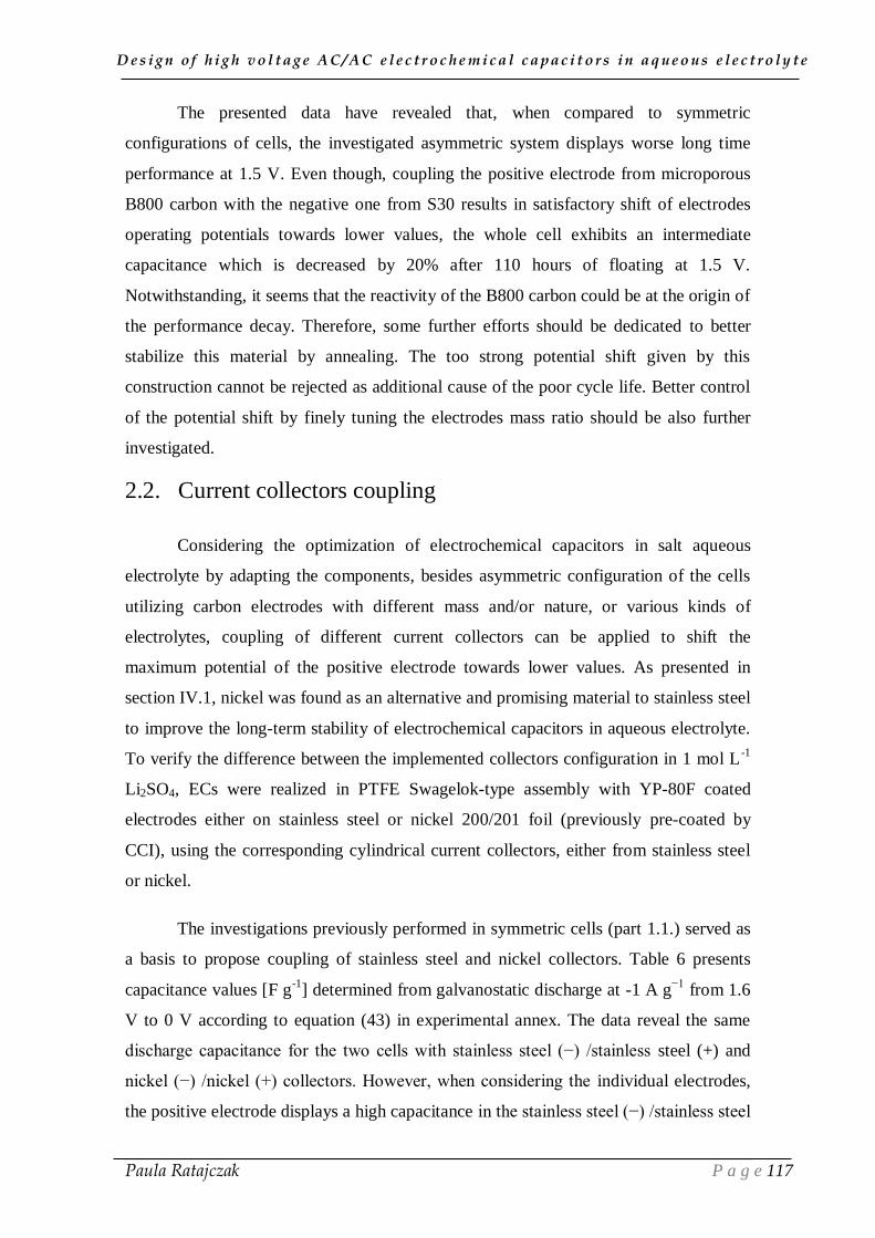
D e s i g n o f h i g h v o l t a g e A C / A C e l e c t r o c h e m i c a l c a p a c i t o r s i n a q u e o u s e l e c t r o l y t e
Paula Ratajczak P a g e 117
The presented data have revealed that, when compared to symmetric
configurations of cells, the investigated asymmetric system displays worse long time
performance at 1.5 V. Even though, coupling the positive electrode from microporous
B800 carbon with the negative one from S30 results in satisfactory shift of electrodes
operating potentials towards lower values, the whole cell exhibits an intermediate
capacitance which is decreased by 20% after 110 hours of floating at 1.5 V.
Notwithstanding, it seems that the reactivity of the B800 carbon could be at the origin of
the performance decay. Therefore, some further efforts should be dedicated to better
stabilize this material by annealing. The too strong potential shift given by this
construction cannot be rejected as additional cause of the poor cycle life. Better control
of the potential shift by finely tuning the electrodes mass ratio should be also further
investigated.
2.2. Current collectors coupling
Considering the optimization of electrochemical capacitors in salt aqueous
electrolyte by adapting the components, besides asymmetric configuration of the cells
utilizing carbon electrodes with different mass and/or nature, or various kinds of
electrolytes, coupling of different current collectors can be applied to shift the
maximum potential of the positive electrode towards lower values. As presented in
section IV.1, nickel was found as an alternative and promising material to stainless steel
to improve the long-term stability of electrochemical capacitors in aqueous electrolyte.
To verify the difference between the implemented collectors configuration in 1 mol L-1
Li2SO4, ECs were realized in PTFE Swagelok-type assembly with YP-80F coated
electrodes either on stainless steel or nickel 200/201 foil (previously pre-coated by
CCI), using the corresponding cylindrical current collectors, either from stainless steel
or nickel.
The investigations previously performed in symmetric cells (part 1.1.) served as
a basis to propose coupling of stainless steel and nickel collectors. Table 6 presents
capacitance values [F g-1
] determined from galvanostatic discharge at -1 A g−1
from 1.6
V to 0 V according to equation (43) in experimental annex. The data reveal the same
discharge capacitance for the two cells with stainless steel (−) /stainless steel (+) and
nickel (−) /nickel (+) collectors. However, when considering the individual electrodes,
the positive electrode displays a high capacitance in the stainless steel (−) /stainless steel
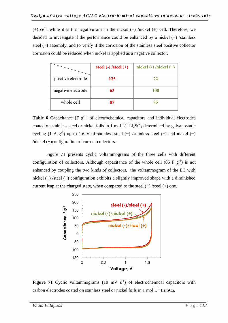
D e s i g n o f h i g h v o l t a g e A C / A C e l e c t r o c h e m i c a l c a p a c i t o r s i n a q u e o u s e l e c t r o l y t e
Paula Ratajczak P a g e 118
(+) cell, while it is the negative one in the nickel (−) /nickel (+) cell. Therefore, we
decided to investigate if the performance could be enhanced by a nickel (−) /stainless
steel (+) assembly, and to verify if the corrosion of the stainless steel positive collector
corrosion could be reduced when nickel is applied as a negative collector.
steel (-) /steel (+) nickel (-) /nickel (+)
positive electrode 125 72
negative electrode 63 100
whole cell 87 85
Table 6 Capacitance [F g-1
] of electrochemical capacitors and individual electrodes
coated on stainless steel or nickel foils in 1 mol L-1
Li2SO4 determined by galvanostatic
cycling (1 A g-1
) up to 1.6 V of stainless steel (−) /stainless steel (+) and nickel (−)
/nickel (+)configuration of current collectors.
Figure 71 presents cyclic voltammograms of the three cells with different
configuration of collectors. Although capacitance of the whole cell (85 F g-1
) is not
enhanced by coupling the two kinds of collectors, the voltammogram of the EC with
nickel (−) /steel (+) configuration exhibits a slightly improved shape with a diminished
current leap at the charged state, when compared to the steel (−) /steel (+) one.
Figure 71 Cyclic voltammograms (10 mV s-1
) of electrochemical capacitors with
carbon electrodes coated on stainless steel or nickel foils in 1 mol L-1
Li2SO4.
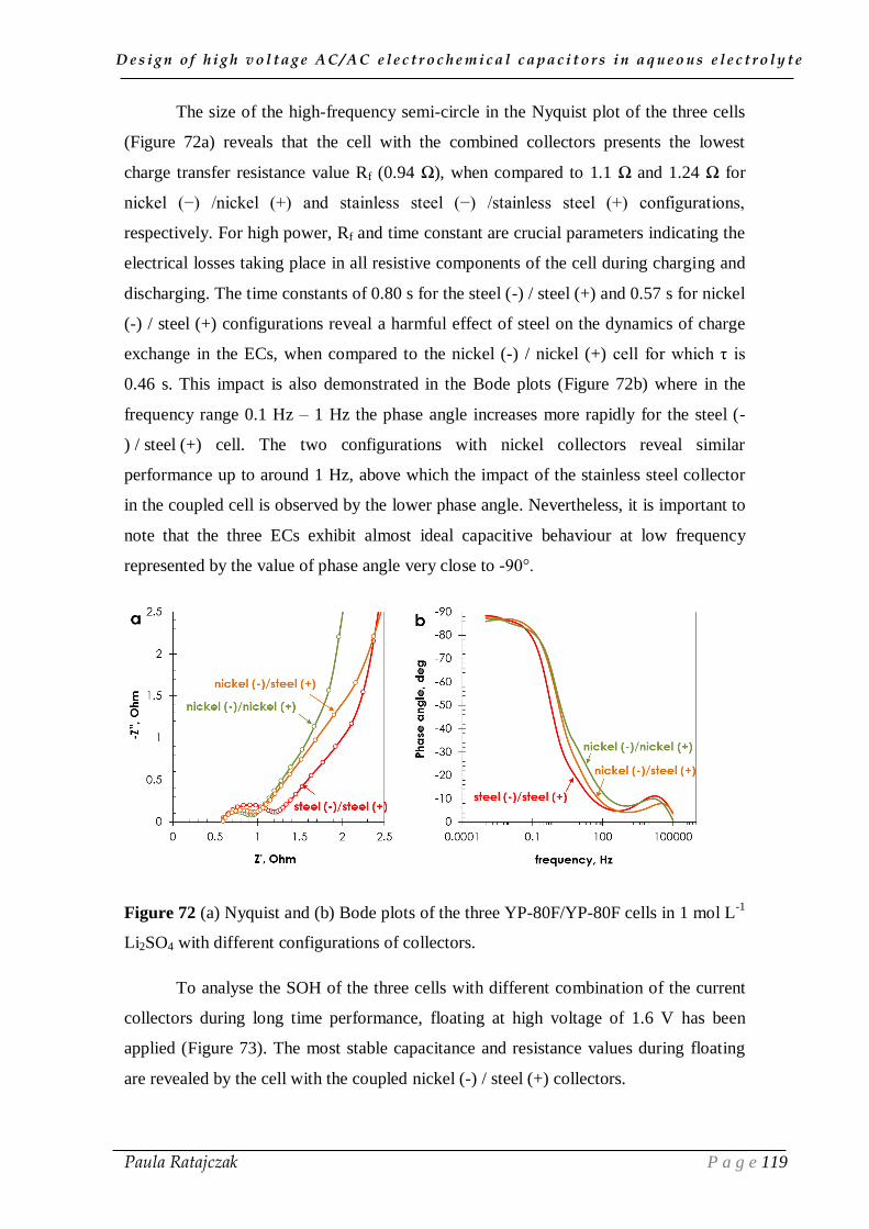
D e s i g n o f h i g h v o l t a g e A C / A C e l e c t r o c h e m i c a l c a p a c i t o r s i n a q u e o u s e l e c t r o l y t e
Paula Ratajczak P a g e 119
The size of the high-frequency semi-circle in the Nyquist plot of the three cells
(Figure 72a) reveals that the cell with the combined collectors presents the lowest
charge transfer resistance value Rf (0.94 Ω), when compared to 1.1 Ω and 1.24 Ω for
nickel (−) /nickel (+) and stainless steel (−) /stainless steel (+) configurations,
respectively. For high power, Rf and time constant are crucial parameters indicating the
electrical losses taking place in all resistive components of the cell during charging and
discharging. The time constants of 0.80 s for the steel (-) / steel (+) and 0.57 s for nickel
(-) / steel (+) configurations reveal a harmful effect of steel on the dynamics of charge
exchange in the ECs, when compared to the nickel (-) / nickel (+) cell for which τ is
0.46 s. This impact is also demonstrated in the Bode plots (Figure 72b) where in the
frequency range 0.1 Hz – 1 Hz the phase angle increases more rapidly for the steel (-
) / steel (+) cell. The two configurations with nickel collectors reveal similar
performance up to around 1 Hz, above which the impact of the stainless steel collector
in the coupled cell is observed by the lower phase angle. Nevertheless, it is important to
note that the three ECs exhibit almost ideal capacitive behaviour at low frequency
represented by the value of phase angle very close to -90°.
Figure 72 (a) Nyquist and (b) Bode plots of the three YP-80F/YP-80F cells in 1 mol L-1
Li2SO4 with different configurations of collectors.
To analyse the SOH of the three cells with different combination of the current
collectors during long time performance, floating at high voltage of 1.6 V has been
applied (Figure 73). The most stable capacitance and resistance values during floating
are revealed by the cell with the coupled nickel (-) / steel (+) collectors.

D e s i g n o f h i g h v o l t a g e A C / A C e l e c t r o c h e m i c a l c a p a c i t o r s i n a q u e o u s e l e c t r o l y t e
Paula Ratajczak P a g e 120
Figure 73 (a) Capacitance and (b) resistance evolution during floating at 1.6 V of YP-
80F/YP-80F capacitors in 1 mol L-1
Li2SO4 with electrodes coated on stainless steel and
nickel collectors.
Once opening the YP-80F_nickel (-) / YP-80F_steel (+) cell after 120 hours of
floating at 1.6 V, no corrosion of the positive current collector was observed, although
some green deposits appeared on the negative one. The mixed-conductive nickel
compounds, formed on the surface of the negative current collector during floating, did
not affect the cell performance. The decrease of capacitive current at voltage higher than
1 V is much less pronounced as in the case of the two other cells using stainless steel
collectors (Figure 74).
Figure 74 CVs (10 mV s-1
) recorded after 120 hours of floating at 1.6 V on YP-
80F/YP-80F capacitors with different current collectors in 1 mol L-1
Li2SO4.
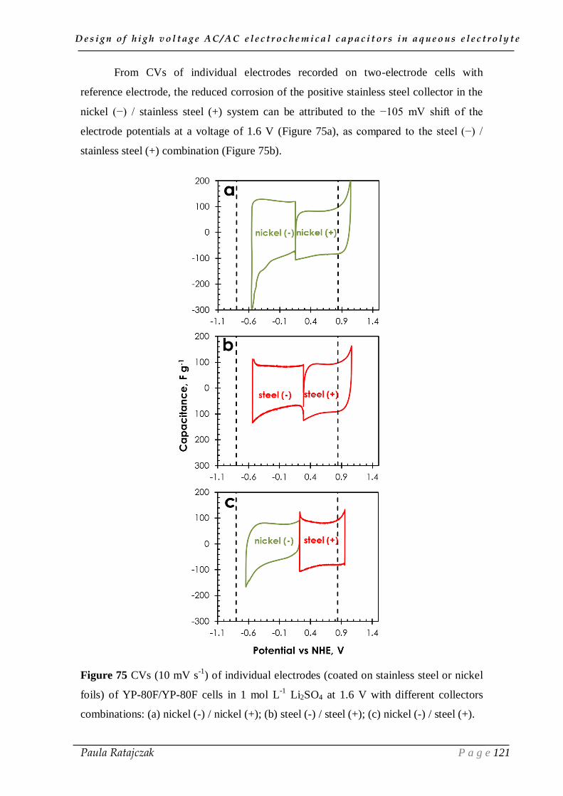
D e s i g n o f h i g h v o l t a g e A C / A C e l e c t r o c h e m i c a l c a p a c i t o r s i n a q u e o u s e l e c t r o l y t e
Paula Ratajczak P a g e 121
From CVs of individual electrodes recorded on two-electrode cells with
reference electrode, the reduced corrosion of the positive stainless steel collector in the
nickel (−) / stainless steel (+) system can be attributed to the −105 mV shift of the
electrode potentials at a voltage of 1.6 V (Figure 75a), as compared to the steel (−) /
stainless steel (+) combination (Figure 75b).
Figure 75 CVs (10 mV s-1
) of individual electrodes (coated on stainless steel or nickel
foils) of YP-80F/YP-80F cells in 1 mol L-1
Li2SO4 at 1.6 V with different collectors
combinations: (a) nickel (-) / nickel (+); (b) steel (-) / steel (+); (c) nickel (-) / steel (+).

D e s i g n o f h i g h v o l t a g e A C / A C e l e c t r o c h e m i c a l c a p a c i t o r s i n a q u e o u s e l e c t r o l y t e
Paula Ratajczak P a g e 122
The CV of the positive electrode in the nickel (−) / stainless steel (+) system
(Figure 75c) discloses a smaller anodic current leap, as compared to the symmetric
collector combinations (Figure 75a and b). Such characteristics traduce diminished
electrolyte decomposition, electrode oxidation and/or formation of corrosion products
on the positive current collector. Moreover, the accumulation of Ni(II) and Ni(III)
derivatives may contribute to polarize the surface of electrodes, and thus, cause a shift
of the EOCP from 0.285 V (Figure 75b) to 0.224 V vs NHE (Figure 75c) [209].
The performance of the capacitors in 1 mol L−1
Li2SO4 electrolyte is improved
by using both nickel (-) / nickel (+) and nickel (-) / steel (+) collectors configuration
when high voltages are applied. However, it would be worth to characterise the nature
of the nickel deposits formed after long-term operation, their actual effect on the cell’s
performance and to investigate strategies for reducing their creation.
IV.3. Conclusion
Strategies to improve the long time performance of AC/AC electrochemical
capacitors in neutral salt aqueous electrolyte were presented in this chapter. The
undertaken tactics intended to reduce the corrosion of stainless steel collectors and to
avoid the decomposition of aqueous electrolyte by shifting the operating electrodes
potentials to lower values.
The reduction of ECs lifetime due to collectors corrosion can be prevented by:
(i) using non-corrodible nickel collectors; (ii) avoiding deposition of the corrosion
products on the electrode-collector plane by coating the electrode material on metallic
foils; (iii) adding a corrosion inhibitor to lithium sulfate electrolyte.
As presented in chapter III, the maximum voltage for long term operation of
S30/S30 electrochemical capacitors with stainless steel collectors under floating is 1.5
V, while the S30/S30 system with nickel collectors can operate up to 1.6 V without
deterioration of electrochemical performance after 120 hours of accelerated ageing.
Due to the well-developed surface area of annealed nickel, the reactivity during
electrochemical ageing in aqueous medium is certainly much higher than in case of
plain nickel, leading to corrosion of the collectors and deterioration of electrochemical
performance
D e s i g n o f h i g h v o l t a g e A C / A C e l e c t r o c h e m i c a l c a p a c i t o r s i n a q u e o u s e l e c t r o l y t e
Paula Ratajczak P a g e 123
A good adhesion of carbon coating to the substrate and protection of the
electrode/substrate interface from accumulation of decomposition products is a key
factor in manufacturing of carbon electrodes by coating. Therefore, the application of
conductive carbon ink (CCI) pre-coating between the metallic substrate and the
electrode material appears to be necessary, in order to ensure satisfactory long-term
performance of electrochemical capacitors in neutral aqueous electrolytes at high
floating voltage.
The addition of 0.1 mol L-1
Na2MoO4 to 1 mol L-1
Li2SO4 inhibits the corrosion
of the positive stainless steel collectors and enhances capacitance through faradaic
contributions. However, in order to avoid oxidation of carbon electrodes after long time
performance at high voltage, further improvement of the AC/AC electrochemical
capacitor in neutral aqueous electrolytes with corrosion inhibitor is needed.
Coupling a highly microporous B800 carbon as positive electrode with industrial
S30 as negative one results in satisfactory shift of electrodes operating potentials
towards lower values. However, when compared to symmetric configurations of cells,
the investigated asymmetric system displays worse long time operation at 1.5 V. Since
the reactivity of the B800 carbon seems to be at the origin of the performance decay,
annealing of this material should be performed.
By using nickel (-) / nickel (+) and nickel (-) / steel (+) collectors configuration,
the performance of the capacitors in 1 mol L−1
Li2SO4 electrolyte is improved.
Although, the appearance of the residues does not affect the performance of the cell
during 120 hours of floating at 1.6 V, it would be worth to characterise the nature of the
nickel deposits formed after long-term operation.
D e s i g n o f h i g h v o l t a g e A C / A C e l e c t r o c h e m i c a l c a p a c i t o r s i n a q u e o u s e l e c t r o l y t e
Paula Ratajczak P a g e 124
CHAPTER V
TOWARDS A NEW CONCEPT
OF HIGH VOLTAGE AC/AC CAPACITOR
IN AQUEOUS ELECTROLYTES
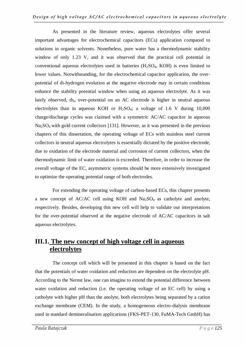
D e s i g n o f h i g h v o l t a g e A C / A C e l e c t r o c h e m i c a l c a p a c i t o r s i n a q u e o u s e l e c t r o l y t e
Paula Ratajczak P a g e 125
As presented in the literature review, aqueous electrolytes offer several
important advantages for electrochemical capacitors (ECs) application compared to
solutions in organic solvents. Nonetheless, pure water has a thermodynamic stability
window of only 1.23 V, and it was observed that the practical cell potential in
conventional aqueous electrolytes used in batteries (H2SO4, KOH) is even limited to
lower values. Notwithstanding, for the electrochemical capacitor application, the over-
potential of di-hydrogen evolution at the negative electrode may in certain conditions
enhance the stability potential window when using an aqueous electrolyte. As it was
lately observed, this over-potential on an AC electrode is higher in neutral aqueous
electrolytes than in aqueous KOH or H2SO4; a voltage of 1.6 V during 10,000
charge/discharge cycles was claimed with a symmetric AC/AC capacitor in aqueous
Na2SO4 with gold current collectors [131]. However, as it was presented in the previous
chapters of this dissertation, the operating voltage of ECs with stainless steel current
collectors in neutral aqueous electrolytes is essentially dictated by the positive electrode,
due to oxidation of the electrode material and corrosion of current collectors, when the
thermodynamic limit of water oxidation is exceeded. Therefore, in order to increase the
overall voltage of the EC, asymmetric systems should be more extensively investigated
to optimize the operating potential range of both electrodes.
For extending the operating voltage of carbon-based ECs, this chapter presents
a new concept of AC/AC cell using KOH and Na2SO4 as catholyte and anolyte,
respectively. Besides, developing this new cell will help to validate our interpretations
for the over-potential observed at the negative electrode of AC/AC capacitors in salt
aqueous electrolytes.
III.1. The new concept of high voltage cell in aqueous
electrolytes
The concept cell which will be presented in this chapter is based on the fact
that the potentials of water oxidation and reduction are dependent on the electrolyte pH.
According to the Nernst law, one can imagine to extend the potential difference between
water oxidation and reduction (i.e. the operating voltage of an EC cell) by using a
catholyte with higher pH than the anolyte, both electrolytes being separated by a cation
exchange membrane (CEM). In the study, a homogeneous electro-dialysis membrane
used in standard demineralisation applications (FKS-PET-130, FuMA-Tech GmbH) has

D e s i g n o f h i g h v o l t a g e A C / A C e l e c t r o c h e m i c a l c a p a c i t o r s i n a q u e o u s e l e c t r o l y t e
Paula Ratajczak P a g e 126
been chosen as CEM, due to its high chemical stability (pH 5-14) and relatively good
selectivity (>96%). The nature and concentration of the electrolytes were practically
imposed by the characteristics of the selected CEM. They were selected for keeping
chemical inertness vs the CEM and relatively constant pH in both anodic and cathodic
compartments during the whole electrochemical experiment. After systematic
investigations based on the latter criteria, our final choice was 0.5 mol L-1
KOH as
catholyte and 1.0 mol L-1
Na2SO4 as anolyte.
The electrolyte decomposition potentials E vs NHE of half-cells in 0.5 mol L-1
KOH (pH= 13.2) and in 1.0 mol L-1
Na2SO4 (pH= 6.6) at equilibrium are given by
Nernst equations (41) and (42), respectively [210]:
𝑬− = −𝟎. 𝟎𝟓𝟗𝟏𝒑𝑯 = −𝟎. 𝟕𝟖𝟎 𝑽 (41)
𝑬+ = 𝟏. 𝟐𝟑 + (−𝟎. 𝟎𝟓𝟗𝟏𝒑𝑯) = 𝟎. 𝟖𝟒𝟎 𝑽 (42)
When the negative electrode potential is below E-, di-hydrogen evolves from the
catholyte. In turn, if the potential of the positive electrode is higher than E+, water from
the anolyte is oxidized producing nascent oxygen which may: (i) provoke corrosion of
the positive stainless steel current collector; (ii) oxidize the AC carbon electrode; (iii) or
evolve as di-oxygen. It follows, that the full cell should be theoretically able to operate
safely up to 0.840 – (-0.780) = 1.620 V, which is much more than the thermodynamic
limit of water decomposition (1.23 V).
Accordingly to the theory of the extended stability window due to the existing
pH difference between the cathodic and anodic compartment, one might ask to replace
the neutral Na2SO4 by, e.g., acidic solution. However, if sulfuric acid would be used as
anolyte, during charging, protons would migrate through the membrane towards the
negatively polarized electrode and cause neutralization of the initially basic catholyte.
Figure 76 shows the principle of cell operation, when it is charged with a
power generator. Due to the electrical potential difference between the electrodes, the
SO42-
ions migrate towards the positive electrode, where they are stored in the pores of
carbon. The sodium ions from the anolyte migrate through the CEM towards the
catholyte and are adsorbed together with potassium ions on the active surface of the
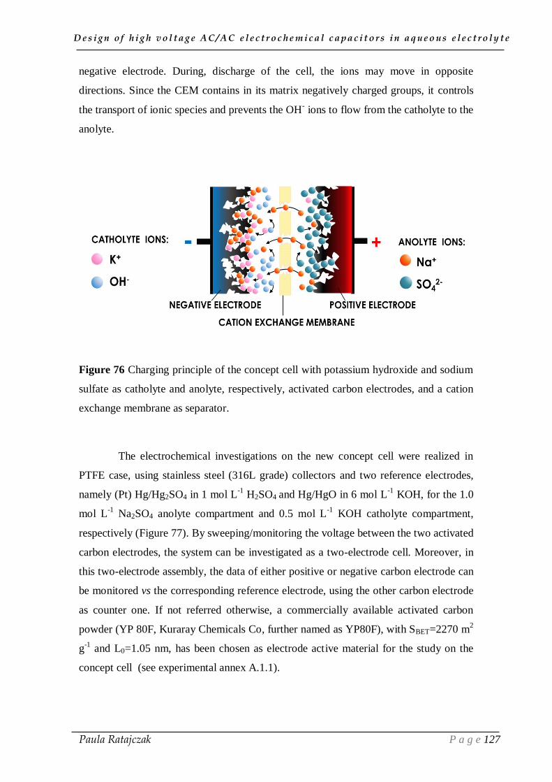
D e s i g n o f h i g h v o l t a g e A C / A C e l e c t r o c h e m i c a l c a p a c i t o r s i n a q u e o u s e l e c t r o l y t e
Paula Ratajczak P a g e 127
negative electrode. During, discharge of the cell, the ions may move in opposite
directions. Since the CEM contains in its matrix negatively charged groups, it controls
the transport of ionic species and prevents the OH- ions to flow from the catholyte to the
anolyte.
Figure 76 Charging principle of the concept cell with potassium hydroxide and sodium
sulfate as catholyte and anolyte, respectively, activated carbon electrodes, and a cation
exchange membrane as separator.
The electrochemical investigations on the new concept cell were realized in
PTFE case, using stainless steel (316L grade) collectors and two reference electrodes,
namely (Pt) Hg/Hg2SO4 in 1 mol L-1
H2SO4 and Hg/HgO in 6 mol L-1
KOH, for the 1.0
mol L-1
Na2SO4 anolyte compartment and 0.5 mol L-1
KOH catholyte compartment,
respectively (Figure 77). By sweeping/monitoring the voltage between the two activated
carbon electrodes, the system can be investigated as a two-electrode cell. Moreover, in
this two-electrode assembly, the data of either positive or negative carbon electrode can
be monitored vs the corresponding reference electrode, using the other carbon electrode
as counter one. If not referred otherwise, a commercially available activated carbon
powder (YP 80F, Kuraray Chemicals Co, further named as YP80F), with SBET=2270 m2
g-1
and L0=1.05 nm, has been chosen as electrode active material for the study on the
concept cell (see experimental annex A.1.1).
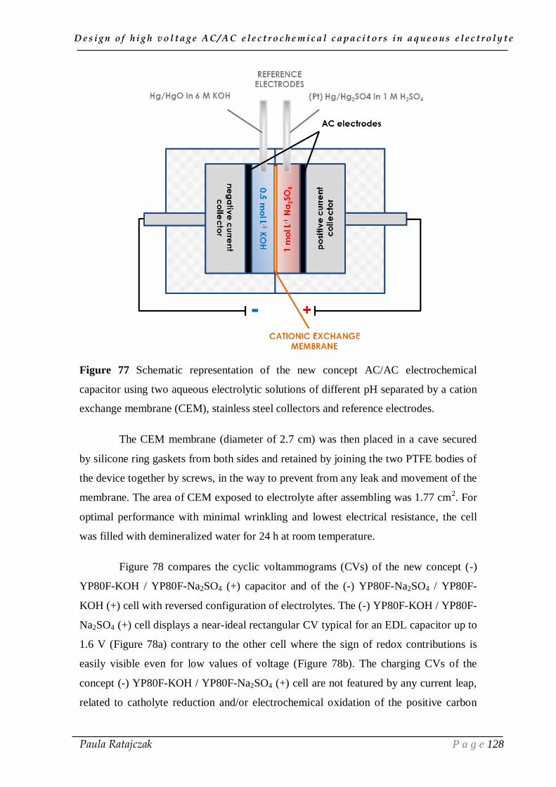
D e s i g n o f h i g h v o l t a g e A C / A C e l e c t r o c h e m i c a l c a p a c i t o r s i n a q u e o u s e l e c t r o l y t e
Paula Ratajczak P a g e 128
Figure 77 Schematic representation of the new concept AC/AC electrochemical
capacitor using two aqueous electrolytic solutions of different pH separated by a cation
exchange membrane (CEM), stainless steel collectors and reference electrodes.
The CEM membrane (diameter of 2.7 cm) was then placed in a cave secured
by silicone ring gaskets from both sides and retained by joining the two PTFE bodies of
the device together by screws, in the way to prevent from any leak and movement of the
membrane. The area of CEM exposed to electrolyte after assembling was 1.77 cm2. For
optimal performance with minimal wrinkling and lowest electrical resistance, the cell
was filled with demineralized water for 24 h at room temperature.
Figure 78 compares the cyclic voltammograms (CVs) of the new concept (-)
YP80F-KOH / YP80F-Na2SO4 (+) capacitor and of the (-) YP80F-Na2SO4 / YP80F-
KOH (+) cell with reversed configuration of electrolytes. The (-) YP80F-KOH / YP80F-
Na2SO4 (+) cell displays a near-ideal rectangular CV typical for an EDL capacitor up to
1.6 V (Figure 78a) contrary to the other cell where the sign of redox contributions is
easily visible even for low values of voltage (Figure 78b). The charging CVs of the
concept (-) YP80F-KOH / YP80F-Na2SO4 (+) cell are not featured by any current leap,
related to catholyte reduction and/or electrochemical oxidation of the positive carbon
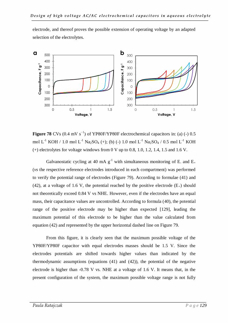
D e s i g n o f h i g h v o l t a g e A C / A C e l e c t r o c h e m i c a l c a p a c i t o r s i n a q u e o u s e l e c t r o l y t e
Paula Ratajczak P a g e 129
electrode, and thereof proves the possible extension of operating voltage by an adapted
selection of the electrolytes.
Figure 78 CVs (0.4 mV s−1
) of YP80F/YP80F electrochemical capacitors in: (a) (-) 0.5
mol L-1
KOH / 1.0 mol L-1
Na2SO4 (+); (b) (-) 1.0 mol L-1
Na2SO4 / 0.5 mol L-1
KOH
(+) electrolytes for voltage windows from 0 V up to 0.8, 1.0, 1.2, 1.4, 1.5 and 1.6 V.
Galvanostatic cycling at 40 mA g-1
with simultaneous monitoring of E- and E+
(vs the respective reference electrodes introduced in each compartment) was performed
to verify the potential range of electrodes (Figure 79). According to formulae (41) and
(42), at a voltage of 1.6 V, the potential reached by the positive electrode (E+) should
not theoretically exceed 0.84 V vs NHE. However, even if the electrodes have an equal
mass, their capacitance values are uncontrolled. According to formula (40), the potential
range of the positive electrode may be higher than expected [129], leading the
maximum potential of this electrode to be higher than the value calculated from
equation (42) and represented by the upper horizontal dashed line on Figure 79.
From this figure, it is clearly seen that the maximum possible voltage of the
YP80F/YP80F capacitor with equal electrodes masses should be 1.5 V. Since the
electrodes potentials are shifted towards higher values than indicated by the
thermodynamic assumptions (equations (41) and (42)), the potential of the negative
electrode is higher than -0.78 V vs. NHE at a voltage of 1.6 V. It means that, in the
present configuration of the system, the maximum possible voltage range is not fully
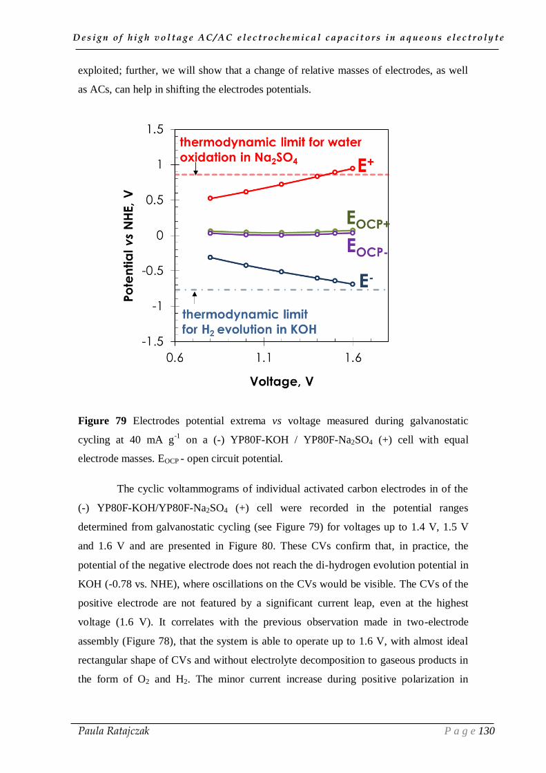
D e s i g n o f h i g h v o l t a g e A C / A C e l e c t r o c h e m i c a l c a p a c i t o r s i n a q u e o u s e l e c t r o l y t e
Paula Ratajczak P a g e 130
exploited; further, we will show that a change of relative masses of electrodes, as well
as ACs, can help in shifting the electrodes potentials.
Figure 79 Electrodes potential extrema vs voltage measured during galvanostatic
cycling at 40 mA g-1
on a (-) YP80F-KOH / YP80F-Na2SO4 (+) cell with equal
electrode masses. EOCP - open circuit potential.
The cyclic voltammograms of individual activated carbon electrodes in of the
(-) YP80F-KOH/YP80F-Na2SO4 (+) cell were recorded in the potential ranges
determined from galvanostatic cycling (see Figure 79) for voltages up to 1.4 V, 1.5 V
and 1.6 V and are presented in Figure 80. These CVs confirm that, in practice, the
potential of the negative electrode does not reach the di-hydrogen evolution potential in
KOH (-0.78 vs. NHE), where oscillations on the CVs would be visible. The CVs of the
positive electrode are not featured by a significant current leap, even at the highest
voltage (1.6 V). It correlates with the previous observation made in two-electrode
assembly (Figure 78), that the system is able to operate up to 1.6 V, with almost ideal
rectangular shape of CVs and without electrolyte decomposition to gaseous products in
the form of O2 and H2. The minor current increase during positive polarization in
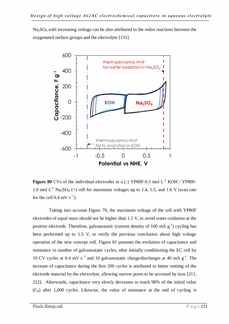
D e s i g n o f h i g h v o l t a g e A C / A C e l e c t r o c h e m i c a l c a p a c i t o r s i n a q u e o u s e l e c t r o l y t e
Paula Ratajczak P a g e 131
Na2SO4 with increasing voltage can be also attributed to the redox reactions between the
oxygenated surface groups and the electrolyte [131].
Figure 80 CVs of the individual electrodes in a (-) YP80F-0.5 mol L-1
KOH / YP80F-
1.0 mol L-1
Na2SO4 (+) cell for maximum voltages up to 1.4, 1.5, and 1.6 V (scan rate
for the cell 0.4 mV s−1
).
Taking into account Figure 79, the maximum voltage of the cell with YP80F
electrodes of equal mass should not be higher than 1.5 V, to avoid water oxidation at the
positive electrode. Therefore, galvanostatic (current density of 100 mA g-1
) cycling has
been performed up to 1.5 V, to verify the previous conclusion about high voltage
operation of the new concept cell. Figure 81 presents the evolution of capacitance and
resistance vs number of galvanostatic cycles, after initially conditioning the EC cell by
10 CV cycles at 0.4 mV s−1
and 10 galvanostatic charge/discharges at 40 mA g-1
. The
increase of capacitance during the first 200 cycles is attributed to better wetting of the
electrode material by the electrolyte, allowing narrow pores to be accessed by ions [211,
212]. Afterwards, capacitance very slowly decreases to reach 98% of the initial value
(C0) after 1,000 cycles. Likewise, the value of resistance at the end of cycling is

D e s i g n o f h i g h v o l t a g e A C / A C e l e c t r o c h e m i c a l c a p a c i t o r s i n a q u e o u s e l e c t r o l y t e
Paula Ratajczak P a g e 132
increased by only 20 % as compared to the ESR in the first cycle (R0). Overall, within
this number of cycles, the SOH of the cell is still very good, with capacitance and
resistance variations below the generally accepted end-of-life criteria [187].
Figure 81 Effect of galvanostatic (100 mA g-1
) cycling up to 1.5 V on capacitance and
resistance of the (-) YP80F-KOH /YP80F-Na2SO4 (+) cell.
After cycling of the new concept cell at 1.5 V, no traces of corrosion on the
positive stainless steel collector were noticed. During the long time performance, the
anolyte pH increased up to 8.9 after 550 galvanostatic cycles, and then did not change
anymore until the end of cycling; taking into account the initial pH value of 6.5, this pH
increase traduces almost negligible OH- migration to the anolyte during cycling.
Notwithstanding, the process of steel corrosion remains inhibited in the anolyte pH
range close to neutrality (6.5-8.9).
To summarize, the presented concept of carbon-based electrochemical capacitor
using two aqueous electrolytic solutions (KOH (-) / Na2SO4 (+)) separated by a CEM
has been validated by the electrochemical investigations. Due to the pH difference
between 0.5 mol L-1
potassium hydroxide as catholyte and 1.0 mol L-1
sodium sulfate as
anolyte, the theoretical potential difference between water oxidation and reduction is
increased to 1.62 V. However, when the system with two identical carbon electrodes is
charged up to a voltage of 1.6 V, there is still a waste range of negative potential which
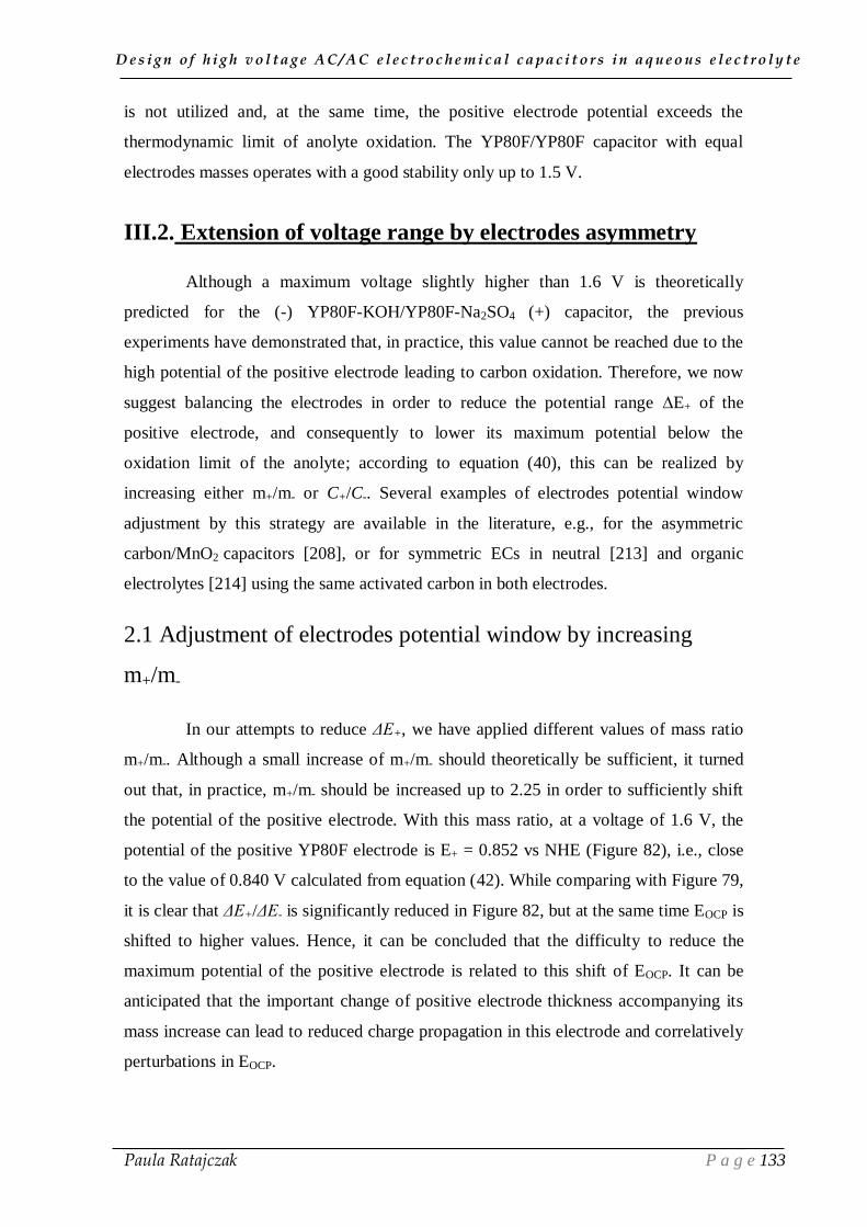
D e s i g n o f h i g h v o l t a g e A C / A C e l e c t r o c h e m i c a l c a p a c i t o r s i n a q u e o u s e l e c t r o l y t e
Paula Ratajczak P a g e 133
is not utilized and, at the same time, the positive electrode potential exceeds the
thermodynamic limit of anolyte oxidation. The YP80F/YP80F capacitor with equal
electrodes masses operates with a good stability only up to 1.5 V.
III.2. Extension of voltage range by electrodes asymmetry
Although a maximum voltage slightly higher than 1.6 V is theoretically
predicted for the (-) YP80F-KOH/YP80F-Na2SO4 (+) capacitor, the previous
experiments have demonstrated that, in practice, this value cannot be reached due to the
high potential of the positive electrode leading to carbon oxidation. Therefore, we now
suggest balancing the electrodes in order to reduce the potential range ∆E+ of the
positive electrode, and consequently to lower its maximum potential below the
oxidation limit of the anolyte; according to equation (40), this can be realized by
increasing either m+/m- or C+/C-. Several examples of electrodes potential window
adjustment by this strategy are available in the literature, e.g., for the asymmetric
carbon/MnO2 capacitors [208], or for symmetric ECs in neutral [213] and organic
electrolytes [214] using the same activated carbon in both electrodes.
2.1 Adjustment of electrodes potential window by increasing
m+/m-
In our attempts to reduce ΔE+, we have applied different values of mass ratio
m+/m-. Although a small increase of m+/m- should theoretically be sufficient, it turned
out that, in practice, m+/m- should be increased up to 2.25 in order to sufficiently shift
the potential of the positive electrode. With this mass ratio, at a voltage of 1.6 V, the
potential of the positive YP80F electrode is E+ = 0.852 vs NHE (Figure 82), i.e., close
to the value of 0.840 V calculated from equation (42). While comparing with Figure 79,
it is clear that ΔE+/ΔE- is significantly reduced in Figure 82, but at the same time EOCP is
shifted to higher values. Hence, it can be concluded that the difficulty to reduce the
maximum potential of the positive electrode is related to this shift of EOCP. It can be
anticipated that the important change of positive electrode thickness accompanying its
mass increase can lead to reduced charge propagation in this electrode and correlatively
perturbations in EOCP.
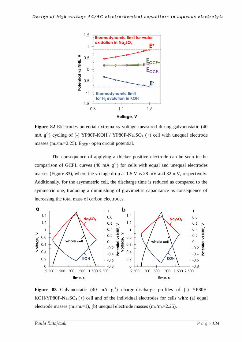
D e s i g n o f h i g h v o l t a g e A C / A C e l e c t r o c h e m i c a l c a p a c i t o r s i n a q u e o u s e l e c t r o l y t e
Paula Ratajczak P a g e 134
Figure 82 Electrodes potential extrema vs voltage measured during galvanostatic (40
mA g-1
) cycling of (-) YP80F-KOH / YP80F-Na2SO4 (+) cell with unequal electrode
masses (m+/m-=2.25). EOCP - open circuit potential.
The consequence of applying a thicker positive electrode can be seen in the
comparison of GCPL curves (40 mA g-1
) for cells with equal and unequal electrodes
masses (Figure 83), where the voltage drop at 1.5 V is 28 mV and 32 mV, respectively.
Additionally, for the asymmetric cell, the discharge time is reduced as compared to the
symmetric one, traducing a diminishing of gravimetric capacitance as consequence of
increasing the total mass of carbon electrodes.
Figure 83 Galvanostatic (40 mA g-1
) charge-discharge profiles of (-) YP80F-
KOH/YP80F-Na2SO4 (+) cell and of the individual electrodes for cells with: (a) equal
electrode masses (m+/m-=1), (b) unequal electrode masses (m+/m-=2.25).
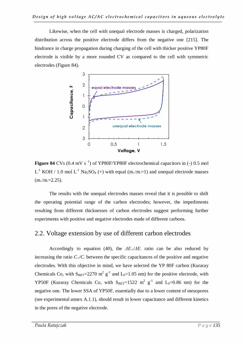
D e s i g n o f h i g h v o l t a g e A C / A C e l e c t r o c h e m i c a l c a p a c i t o r s i n a q u e o u s e l e c t r o l y t e
Paula Ratajczak P a g e 135
Likewise, when the cell with unequal electrode masses is charged, polarization
distribution across the positive electrode differs from the negative one [215]. The
hindrance in charge propagation during charging of the cell with thicker positive YP80F
electrode is visible by a more rounded CV as compared to the cell with symmetric
electrodes (Figure 84).
Figure 84 CVs (0.4 mV s−1
) of YP80F/YP80F electrochemical capacitors in (-) 0.5 mol
L-1
KOH / 1.0 mol L-1
Na2SO4 (+) with equal (m+/m-=1) and unequal electrode masses
(m+/m-=2.25).
The results with the unequal electrodes masses reveal that it is possible to shift
the operating potential range of the carbon electrodes; however, the impediments
resulting from different thicknesses of carbon electrodes suggest performing further
experiments with positive and negative electrodes made of different carbons.
2.2. Voltage extension by use of different carbon electrodes
Accordingly to equation (40), the ΔE+/ΔE- ratio can be also reduced by
increasing the ratio C+/C- between the specific capacitances of the positive and negative
electrodes. With this objective in mind, we have selected the YP 80F carbon (Kuraray
Chemicals Co, with SBET=2270 m2 g
-1 and L0=1.05 nm) for the positive electrode, with
YP50F (Kuraray Chemicals Co, with SBET=1522 m2 g
-1 and L0=0.86 nm) for the
negative one. The lower SSA of YP50F, essentially due to a lower content of mesopores
(see experimental annex A.1.1), should result in lower capacitance and different kinetics
in the pores of the negative electrode.

D e s i g n o f h i g h v o l t a g e A C / A C e l e c t r o c h e m i c a l c a p a c i t o r s i n a q u e o u s e l e c t r o l y t e
Paula Ratajczak P a g e 136
Successfully, the potential of the positive YP80F electrode in the (-) YP50F-
KOH / YP80F-Na2SO4 (+) cell is diminished to E+ = 0.844 vs NHE at a voltage of 1.6
V (Figure 85a), value which is close to of the theoretical one of 0.840 V calculated from
equation (42). Moreover, contrary to the (-) YP80F/YP80F (+) cell with unequal
electrode masses (m+/m-=2.25) (Figure 82), EOCP is not shifted to higher values when
the two different carbon electrodes are used (Figure 85a). Overall, as seen in Figure 10a,
the potential ranges of both electrodes for the (-) YP50F-KOH / YP80F-Na2SO4 (+) cell
perfectly fit within the thermodynamic stability limits represented by the dashed lines.
The near-rectangular shape of CV (0.4 mV s−1
) up to 1.5 V for the (-) YP50F-
KOH / YP80F-Na2SO4 (+) cell with different carbon electrodes in Figure 85b proves
good charge propagation. Contrarily, since the potential of the positive electrode in the
(-) YP80F-KOH / YP80F-Na2SO4 (+) capacitor exceeds the thermodynamic limit for
water oxidation in Na2SO4 (Figure 79), the CV of the cell with the same YP80F
electrodes is featured by a current leap related to carbon electrochemical oxidation.
Since, such phenomenon is not revealed by the (-) YP50F-KOH / YP80F-Na2SO4 (+)
cell, which exhibits nearly constant capacitive current during the CV scan, the possible
extension of operating voltage by an adapted selection of the electrode materials seems
to be proved.
Figure 85 (a) Electrodes potential extrema vs. voltage measured during galvanostatic
(40 mA g-1
) cycling of a (-) YP50F-KOH / YP80F-Na2SO4 (+) cell; (b) CVs (0.4 mV
s−1
) of (-) YP50F-KOH / YP80F-Na2SO4 (+) and (-) YP80F-KOH / YP80F-Na2SO4 (+)
cells.

D e s i g n o f h i g h v o l t a g e A C / A C e l e c t r o c h e m i c a l c a p a c i t o r s i n a q u e o u s e l e c t r o l y t e
Paula Ratajczak P a g e 137
As discussed above, the margin before reaching the di-hydrogen evolution
potential at the negative electrode can be utilized either by balancing the mass of the
electrodes or by using different optimized carbons for the positive and negative
electrodes. An adjustment of positive and negative electrodes mass ratio (m+/m-=2.25)
enables to extend the operating cell potential to 1.6 V; however, the higher resistance of
this system due to different thickness of the carbon electrodes suggests optimization of
the cell through different AC electrodes. An application of carbon with different pore
size distribution as electrode active material for positive and negative electrode enables
to extend the operating voltage, and at the same time, to keep good electrochemical
properties of the EC. Since the (-) YP50F/YP80F (+) configuration revealed promising
results in the voltage extension, further experiments, i.e., cycling or accelerated ageing
are obviously planned.
III.3. Conclusion
According to thermodynamic considerations, due to the pH difference between
the basic catholyte and the neutral anolyte, an (-) AC-KOH / AC-Na2SO4 (+) capacitor
can theoretically operate up to 1.62 V. The effect of Galvani potential difference for AC
electrodes in KOH and Na2SO4, as catholyte and anolyte, respectively, has been
validated for a system with equal electrodes masses, which demonstrates good cycle life
up to 1.5 V. The experiments on the (-) YP50F-KOH / YP80F-Na2SO4 (+) cell
confirmed that the operating voltage is essentially limited by the positive carbon
electrode.
The exploration of the effects of electrode materials porosity on voltage
expansion is found to be crucial for enhancing the voltage range in the new concept
KOH (-) / Na2SO4 (+) capacitor. Obviously, there is still plenty of room for future
experiments and for a subsequent design of the cation exchange membrane and current
collectors which appear as ways for developing a new electrochemical capacitor
generation. Notwithstanding, the performed experiments initiated a new direction for
further studies based on this new concept cell, taking into account the advantages of
both alkaline and neutral aqueous media (possibility to use stainless steel or nickel
collectors) to develop high voltage and cheap AC/AC electrochemical capacitors.
D e s i g n o f h i g h v o l t a g e A C / A C e l e c t r o c h e m i c a l c a p a c i t o r s i n a q u e o u s e l e c t r o l y t e
Paula Ratajczak P a g e 138
GENERAL CONCLUSION

D e s i g n o f h i g h v o l t a g e A C / A C e l e c t r o c h e m i c a l c a p a c i t o r s i n a q u e o u s e l e c t r o l y t e
Paula Ratajczak P a g e 139
Improving the energy density, while keeping high power density and long
cycle life, is the main objective in AC/AC electrochemical capacitor development. For
being industrially implemented, such devices should be also cheap and easily
manufactured, environmentally friendly and fulfill all the security requirements. To
design and develop ECs in neutral aqueous electrolyte with stainless steel current
collectors, three directions were particularly explored in this research work: i) the main
factors contributing to ageing of AC-based electrochemical capacitors in lithium sulfate
aqueous electrolyte with stainless steel collectors were disclosed by accelerated ageing
based on potentiostatic floating; ii) strategies were proposed and verified to improve the
long-term performance of the ECs at high voltage while implementing cheap
constituents; iii) a new concept cell, based on two aqueous electrolytic solutions of
different pH has been suggested and validated in order to extend the operating voltage
window. The results obtained by the various physico-chemical and electrochemical
investigations allow the following conclusions to be formulated.
Potentiostatic floating including two-hour floating periods is an accurate method
for accelerated ageing of electrochemical capacitors based on carbon electrodes in
aqueous electrolyte. Owing to the longer periods at high voltage, this test is more
effective for determining ECs operation stability limits than galvanostatic cycling.
The failures which mainly appear during operation of the ECs are an increase of
equivalent series resistance, capacitance loss and electrolyte decomposition. The post-
floating investigations reveal carbon oxidation and accumulation of corrosion products
on the positive electrode as subsequent factors causing ageing. The formed oxygenated
surface groups block the pores, limiting the access of ions to the electrode active
surface, and causing a drop of capacitance, whereas the accumulation of corrosion
products at the electrode/collector interface causes a resistance increase. Moreover, the
gases generated at the electrodes shorten the cell life due to electrolyte depletion and/or
loss of electrode cohesion.
The reduction of ECs lifetime due to collectors’ corrosion has been, at least in
part, prevented by: (i) using non-corrodible nickel collectors; (ii) coating the electrode
material on the metallic collector in order to avoid the accumulation of corrosion
products at the electrode-collector interface; (iii) adding a corrosion inhibitor to lithium
sulfate electrolyte. The deposition of oxidized nickel compounds on the collectors and

D e s i g n o f h i g h v o l t a g e A C / A C e l e c t r o c h e m i c a l c a p a c i t o r s i n a q u e o u s e l e c t r o l y t e
Paula Ratajczak P a g e 140
separator during ageing at 1.6 V is probably associated with the observed pH variations.
Nevertheless, the appearance of these residues does not affect the performance of the
cell which exhibits stable resistance values up to 120 hours at 1.6 V floating voltage.
The application of a conductive carbon ink (CCI) pre-coating on the metallic substrate
improves the adhesion of the carbon coating and prevents from the accumulation of
decomposition products at the electrode/substrate interface. The corrosion of stainless
steel collectors was diminished by adding sodium molybdate inhibitor, which
additionally enhances the cell capacitance.
The other strategy to improve the long-term operation of capacitors in aqueous
media is a downshift of electrodes operating potential to avoid oxidation phenomena at
the positive electrode (i) either by asymmetry of electrode materials; (ii) or by
combining two kinds of cheap collectors. As expected, the maximum potential of the
positive electrode could be reduced by coupling highly microporous Burley tobacco
carbon (B800) as positive electrode with the industrial DLCS30 one as negative
electrode. However, due to important surface functionality and correlated reactivity of
B800, the potential of the positive electrode shifted to higher values during floating,
with subsequent deterioration of electrochemical performance. Finally, the corrosion of
the positive stainless steel collector disappeared by combining (-) nickel and (+)
stainless steel collectors. The potential shift towards lower values results in negligible
electrolyte decomposition, electrode oxidation and/or formation of corrosion products
on the positive current collector, allowing the cell to reach up to 1.6 V.
Due to the pH difference between potassium hydroxide and sodium sulfate
separated by a proton exchange membrane, the new concept AC/AC capacitor is able to
operate up to 1.5 V with a good stability while using stainless steel collectors. By
asymmetry of electrodes, the operating voltage could be extended to 1.6 V.
As research perspectives on AC-based electrochemical capacitors in neutral
salt aqueous electrolytes, in-situ analysis of evolved gases during accelerated ageing, by
coupling gas chromatography (GC) with mass spectrometry (GC/MS), would be useful
to elucidate the real decomposition mechanisms and to suggest adapted strategies (for
example components enhancing recombination processes) to reduce internal pressure
increase and oxidation of electrodes. Analysis by, e.g., X-ray photoelectron
spectroscopy (XPS) of the nickel deposits formed after accelerated ageing on the

D e s i g n o f h i g h v o l t a g e A C / A C e l e c t r o c h e m i c a l c a p a c i t o r s i n a q u e o u s e l e c t r o l y t e
Paula Ratajczak P a g e 141
collectors and separator could provide information about their exact nature and allow
strategies to be proposed for reducing their creation during long-term performance. On
the basis of the aqueous lithium sulfate solution, another important objective would be
to work out an electrolyte formulation for covering a wide temperature range, i.e. from -
40°C to +60°C. The ultimate work on cells implementing aqueous lithium sulfate would
be to build pouch cells including all the optimized components previously identified and
to investigate their electrochemical properties in various environments.
The performance of the new concept cell with two kinds of electrolytes could be
improved by modifying the geometry and also by implementing more stable and highly
conductive CEM with a good selectivity, in order to enhance cycle life and reduce the
cell resistance. Applying gel electrolytes could be also a way to reduce some of the
difficulties inherent to the use of a cationic exchange membrane.
D e s i g n o f h i g h v o l t a g e A C / A C e l e c t r o c h e m i c a l c a p a c i t o r s i n a q u e o u s e l e c t r o l y t e
Paula Ratajczak P a g e 142
EXPERIMENTAL ANNEX

D e s i g n o f h i g h v o l t a g e A C / A C e l e c t r o c h e m i c a l c a p a c i t o r s i n a q u e o u s e l e c t r o l y t e
Paula Ratajczak P a g e 143
A.1. Cell construction
1.1. Materials and chemicals
Electrode materials:
(i) The commercial activated carbons:
DLC Super 30 (Norit) was used for manufacturing pellet electrodes (named in
the main text as S30)
YP-80F (Kuraray Chemicals Co) was used for manufacturing coated electrodes
(named in the main text as YP80F)
YP-80F and YP-50F (Kuraray Chemicals Co) were used as self-standing
electrodes for the new concept cell (named in the main text as YP80F and
YP50F, respectively)
(ii) The tobacco carbon:
Burley carbon (named as B800) was prepared from the leaves’ stems wastes of
tobacco industry carbonized in a tubular furnace under nitrogen flow rate of 100
mL min-1
and heated at 10 °C min-1
up to 800 °C for one hour. The detailed
process of sample preparation is given in the reference [78].
For the post-floating analysis of electrodes by thermoprogrammed desorption
(TPD), self-standing electrodes from activated carbon cloth (ACC 507-20,
Kynol) were selected to avoid the interference of the electrode binder.
Figure A1 Porous texture of carbons used in the study: (a) nitrogen
adsorption/desorption isotherms recorded at 350 °C; (b) Pore size distribution
determined using the 2D-NLDFT model.
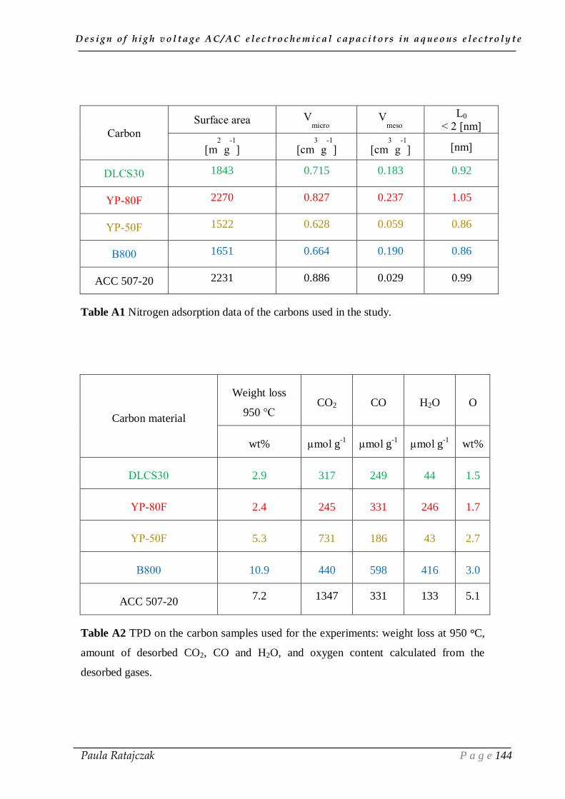
D e s i g n o f h i g h v o l t a g e A C / A C e l e c t r o c h e m i c a l c a p a c i t o r s i n a q u e o u s e l e c t r o l y t e
Paula Ratajczak P a g e 144
Carbon
Surface area Vmicro
Vmeso
L0
< 2 [nm]
[m2
g-1
] [cm3
g-1
] [cm3
g-1
] [nm]
DLCS30 1843 0.715 0.183 0.92
YP-80F 2270 0.827 0.237 1.05
YP-50F 1522 0.628 0.059 0.86
B800 1651 0.664 0.190 0.86
ACC 507-20 2231 0.886 0.029 0.99
Table A1 Nitrogen adsorption data of the carbons used in the study.
Carbon material
Weight loss
950 °C CO2 CO H2O O
wt% µmol g-1
µmol g-1
µmol g-1
wt%
DLCS30 2.9 317 249 44 1.5
YP-80F 2.4 245 331 246 1.7
YP-50F 5.3 731 186 43 2.7
B800 10.9 440 598 416 3.0
ACC 507-20 7.2 1347 331 133 5.1
Table A2 TPD on the carbon samples used for the experiments: weight loss at 950 °C,
amount of desorbed CO2, CO and H2O, and oxygen content calculated from the
desorbed gases.

D e s i g n o f h i g h v o l t a g e A C / A C e l e c t r o c h e m i c a l c a p a c i t o r s i n a q u e o u s e l e c t r o l y t e
Paula Ratajczak P a g e 145
Electrolytes:
(i) The output electrolyte in the study was 1 mol L−1
lithium sulfate (Li2SO4,
Sigma-Aldrich, >99%) (pH = 6.5, conductivity = 64 mS cm-1
)
(ii) In order to reduce the corrosion of current collectors, in some experiments in
chapter V.1, 0.1 mol L−1
sodium molybdate (Sigma Aldrich, >99.5%) has
been added to the Li2SO4 solution, (pH = 6.7, conductivity = 72 mS cm-1
)
(iii) For the new concept cell presented in chapter V, 1 mol L-1
sodium sulfate
(Na2SO4, Sigma-Aldrich, >99%) (pH = 6.6, conductivity = 68 mS cm-1
) and
0.5 mol L-1
potassium hydroxide (KOH, POCh, min. 85%) (pH = 13.2,
conductivity = 56 mS cm-1
) were used as catholyte and anolyte, respectively.
1.2. Preparation of electrodes
Pellet electrodes:
Pellet electrodes were prepared by mixing activated carbon (85 wt. %) with 5 wt.
% polyvinylidene fluoride as binder (PVdF, Kynar HSV900, Arkema) and 5 wt. %
carbon black (C65, Timcal) conductivity enhancer. The three components were mixed
with acetone (Avantor, 99.5%), then rolled to get a film, and the pellets with a
thickness of around 0.3 mm and mass 8–10 mg and 1 cm diameter were pressed under
4.870 kg cm-2
. The prepared electrodes were dried under vacuum at 110°C for 12 hours.
Coated electrodes:
Unless otherwise noted, for realizing coated electrodes, the surface of grade
1.431 stainless steel (Interbelts, thickness = 15 μm) or nickel (Schlenk, thickness = 20
μm) foils was pre-coated with a thin layer (15 μm) of carbon conductive ink (CCI)
(Electrodag™ PF-407A™, Acheson) to provide a rougher surface of the substrate.
Activated carbon YP 80F (83.5 wt. %), carbon black (SUPER C65, Timcal, 8.5 wt. %)
conductivity enhancer and polyvinylidene difluoride (PVdF, Kynar® HSV 900,
Arkema, 8 wt. %) binder dissolved in 1-methyl-2-pyrrolidone (NMP, Sigma-Aldrich)
were mixed with an homogenizer (IKA ULTRA-TURRAX® T 18 basic), and the
obtained slurry was cast with a Doctor Blade applicator (Elcometer® 3600) on the
previously prepared surface of stainless steel or nickel foil. Afterwards, the coating is
dried overnight by slow evaporation in air, followed by heating under vacuum at 120°C

D e s i g n o f h i g h v o l t a g e A C / A C e l e c t r o c h e m i c a l c a p a c i t o r s i n a q u e o u s e l e c t r o l y t e
Paula Ratajczak P a g e 146
for 12 h. 10 mm diameter disk electrodes (mass of active material ~3.5 mg, coating
thickness ~100 μm) were punched out from the coating.
1.3. Cell configurations
Cells with pellet electrodes
Cells with electrodes in the form of pellets were realized by sandwiching a
porous glass microfiber membrane GF/A (Whatman™, thickness = 0.26 mm) between
two pellet electrodes (DLC Super 30, Norit) and two current collectors either from
stainless steel or nickel, using PTFE Swagelok-type vessels with or without inlet for a
reference electrode (Hg/Hg2SO4 in 0.5 mol L-1
H2SO4) (Figure A2). Before being
closed, the assembled system was soaked under vacuum with 1 mol L-1
Li2SO4
electrolytic solution. The current collectors (diameter 1.2 cm) were made from a low
carbon content stainless steel 316L alloy consisting of the following major elements: Fe,
C (0.02%), Cr (16%), Ni (10%) and Mo (2%) or commercially pure nickel 200/201.
Their surface was cleaned with emery paper (P1000) before the investigations.
Figure A2 Schematic representation of the capacitors in PTFE Swagelok-type assembly
with reference electrode.
D e s i g n o f h i g h v o l t a g e A C / A C e l e c t r o c h e m i c a l c a p a c i t o r s i n a q u e o u s e l e c t r o l y t e
Paula Ratajczak P a g e 147
Cells with coated electrodes
Electrochemical capacitors with electrodes coated on stainless steel or nickel
were realized in PTFE Swagelok-type vessel with an additional inlet for Hg/Hg2SO4
reference electrode for measurements of CVs of individual electrodes, by sandwiching
an absorptive glass mat separator (AGM, Bernard Dumas, thickness = 0.52 mm)
between two coated electrodes (Kuraray YP-80F) and cylindrical current collectors,
either from stainless steel 316L or nickel 200/201 (in analogy to the cells with pellet
electrodes). Before being closed, the assembled system was soaked under vacuum with
1 mol L-1
Li2SO4 electrolytic solution.
All the data with reference electrode presented in the manuscript were calculated
vs normal hydrogen electrode (NHE).
A.2. Electrochemical characterizations
The electrochemical properties of the capacitors and the new concept cell were
investigated by cyclic voltammetry (CV), galvanostatic cycling with potential limitation
(GCPL) and impedance spectroscopy (EIS) at open circuit voltage (OCV) in the
frequency range 1 mHz to 100 kHz and amplitude of 5 mV, using a VMP3 multichannel
potentiostat/galvanostat (Bio-Logic Instruments, France). Data were collected using EC-
Lab V10.34 software. Capacitance was calculated from the galvanostatic discharge and
expressed per average active mass of electrodes [F g-1
] according to formula (43):
C = 2 I / [(dV/dt) m] (43)
where I is the current [A], dV/dt is the slope of the discharge curve [V s-1
], m is the
average mass of carbon active material [g] .
A.3. Physico-chemical and surface characterization
Temperature-programmed desorption (TPD) analysis
The surface oxygenated functionality of fresh and aged carbon electrodes
(Kynol, ACC 507-20) was characterized by temperature-programmed desorption (TPD),
using TG equipment (TG209 F1 Iris, NETZSCH) coupled with a mass spectrometer
(QMS 403C Aëolos, NETZSCH). To investigate the evolution of surface chemistry
D e s i g n o f h i g h v o l t a g e A C / A C e l e c t r o c h e m i c a l c a p a c i t o r s i n a q u e o u s e l e c t r o l y t e
Paula Ratajczak P a g e 148
after accelerated ageing, ACC electrodes were taken out from ECs after 120 h of
floating, washed carefully with distilled water to remove the electrolyte and dried under
vacuum at 120 °C. During surface functionality determination by TPD, c.a. 10 mg of
ACC was heated up to 950 °C (heating rate 20 °C min-1
) under helium flow rate of 50
mL min-1
. The surface functional groups evolving as CO2 and CO were quantified after
calcium oxalate monohydrate calibration, taking into account CO disproportionation
[216]. To determine the types of oxygenated complexes formed on the surface of the
aged positive electrode, the deconvolution of CO2 and CO patterns have been made with
a multiple Gaussian function using the Origin 9.0 software.
Porous texture characterisation
In courtesy of Mgr. Piotr Skowron help from our research group, the porous
texture of carbons was determined from nitrogen adsorption/desorption isotherms
recorded at -196 °C using an ASAP2020 (Micrometrics). Prior to the measurements, the
fresh and aged electrodes (around 60 mg) were degassed under vacuum for 36 h at
100°C. The pore size distribution (PSD) was determined using the 2D non-local density
functional theory (2D-NLDFT) [107], the micro Vmicro and mesopore volumes Vmeso
were obtained directly from the calculated cumulative PSDs. The average micropore
size (L0) was determined from the integration of the PSD area for the pores below 2 nm.
Scanning electron microscopy (SEM)
In courtesy of Dr. Eng. Tomasz Rozmanowski, scanning electron microscopy
(SEM) images of nickel 200/201, with and without carbon conductive ink (CCI), and
soft-annealed nickel foils were analysed in a high vacuum mode with the use of Hitachi
Model S-3400N Scanning Electron Microscope with secondary electron (SE) detector.
Magnifications of x50 to x5.00k were obtained with a voltage of 15.0 kV.

D e s i g n o f h i g h v o l t a g e A C / A C e l e c t r o c h e m i c a l c a p a c i t o r s i n a q u e o u s e l e c t r o l y t e
Paula Ratajczak P a g e 149
REFERENCES

D e s i g n o f h i g h v o l t a g e A C / A C e l e c t r o c h e m i c a l c a p a c i t o r s i n a q u e o u s e l e c t r o l y t e
Paula Ratajczak P a g e 150
[1] T. Luo, B. Otto, T. Shiao, A. Maddocks, „Identifying the Global Coal Industry’s
Water Risks,” Cornerstone, 2 (2014) 26-31.
[2] V. Smil, „Energy Transitions: History, Requirements, Prospects,” ABC-CLIO,
California, 2010.
[3] B.E. Conway, „Electrochemical Supercapacitors: Scientific Fundamentals and
Technological Applications,” Kluwer- Plenum, New York, 1999.
[4] F. Béguin, E. Frackowiak, „Carbons for Electrochemical Energy Storage and
Conversion Systems,” CRC Press Taylor & Francis Group, Boca Raton, 2010.
[5] H. von Helmholtz, „Über einige Gesetze der Verteilung elektrischer Ströme in
körperlichen Leitern, mit Anwendung auf die thierisch-elektrischen Versuche,”
Ann. Phys.Chem., 89 (1853) 211-233.
[6] D.L. Chapman, „A contribution to the theory of electrocapillarity,” Phil. Mag., 25
(1913) 475-481.
[7] O. Stern, „The Theory of the Electrolytic Double-Layer,” Zeit. Elektrochem., 30
(1924) 508-516.
[8] D.C. Grahame, „The Electrical Double Layer and the Theory of
Electrocapillarity,” Chem. Rev., 41 (1947) 441-501.
[9] J.O'M. Bockris, M.A.V. Devanathan, K. Muller, „The structure of charged
interfaces,” Proc. R. Soc. London, Ser. A, 274 (1963) 55–79.
[10] F. Béguin, V. Presser, A. Balducci, E. Frąckowiak, „Carbons and Electrolytes for
Advanced Supercapacitors,” Adv. Mater., 26 (2014) 2219–2251.
[11] A.G. Pandolfo, A.F. Hollenkamp, „Carbon properties and their role in
supercapacitors,” J. Power Sources, 157 (2006) 11-27.
[12] J.R. Miller, A.F. Burke, „Electrochemical capacitors: challenges and opportunities
for real-world application,” Electrochem. Soc. Interface, 17 (2008) 53-57.
[13] J.B. Goodenough, Y. Kim, „Challenges for Rechargeable Li Batteries,” Chem.
Mater., 22 (2010) 587-603.
[14] P. Simon, Y. Gogotsi, „Materials for electrochemical capacitors,” Nat. Mater., 7
(2008) 845-854.
[15] S. Lehtimäki, M. Li, J. Salomaa, J. Pörhönen, A. Kalanti, S. Tuukkanen, P. Heljo,
K. Halonen, D. Lupo, „Performance of printable supercapacitors in an RF energy
harvesting circuit,” Int J Elec Power & Energy Systems, 58 (2014) 42-46.
[16] A. Balakrishnan, K.R.V. Subramanian, „Nanostructured Ceramic Oxides for
Supercapacitor Applications,” CRC Press, Boca Raton, 2014.
[17] B.E Conway, V. Birss, J. Wojtowicz, „The role and utilization of
pseudocapacitance for energy storage by supercapacitors,” J. Power Sources, 66
(1997) 1-2.
[18] V. Presser Group, „Interface Materials,” www.leibniz-inm.de, Leibniz, 2015.
[19] A. Kisza, „Elektrochemia I. Jonika,” WNT, Warszawa, 2000.
[20] B.E. Conway, „Electrochemical surface science: The study of monolayers of ad-
D e s i g n o f h i g h v o l t a g e A C / A C e l e c t r o c h e m i c a l c a p a c i t o r s i n a q u e o u s e l e c t r o l y t e
Paula Ratajczak P a g e 151
atoms and solvent molecules at charged metal interfaces,” Progress in surface
science, 16 (1984) 1-137.
[21] E. Frąckowiak, F. Béguin, „Carbon materials for the electrochemical storage of
energy in capacitors,” Carbon, 39 (2001) 937 –950.
[22] E. Frackowiak, F. Béguin, „Electrochemical storage of energy in carbon
nanotubes and nanostructured carbons,” Carbon, 40 (2002) 1775-1787.
[23] J.K. McDonough, A.I. Frolov, V. Presser, J. Niu, C.H. Miller, T. Ubieto, M.V.
Fedorov, Y. Gogotsi, „Influence of the structure of carbon onions on their
electrochemical performance in supercapacitor electrodes,” Carbon, 50 (2012)
3298-3309.
[24] Y. Huang, J. Liang, Y. Chen, „An Overview of the Applications of Graphene-
Based Materials in Supercapacitors,” Small, 8 (2012) 1805-1834.
[25] V. Presser, M. Heon, Y. Gogotsi, „Carbide-Derived Carbons – From Porous
Networks to Nanotubes and Graphene,” Adv. Funct. Mater., 21 (2011) 810-833.
[26] A. Kajdos, A. Kvit, F. Jones, J. Jagiello, G. Yushin, „Tailoring the Pore
Alignment for Rapid Ion Transport in Microporous Carbons,” J Am Chem Soc,
132 (2010) 3252-3253.
[27] S. Boukhalfa, L. He, Y.B. Melnichenko, G. Yushin, „Small angle neutron
scattering for the in-situ probing of ion adsorption inside micropores,” Angew
Chem Int Ed, 52 (2013) 4618–4622.
[28] K. Evanoff, J. Khan, A.A. Balandin, A. Magasinski, W.J. Ready, T.F. Fuller, G.
Yushin, „Towards ultrathick battery electrodes: aligned carbon nanotube-enabled
architecture,” Adv Mater, 24 (2012) 533-537.
[29] S. Boukhalfa, K. Evanoff, G. Yushin, „Atomic layer deposition of vanadium
oxide on carbon nanotubes for high-power supercapacitor electrodes,” Energy
Environ Sci, 5 (2012) 6872–6879.
[30] C. Portet, G. Yushin, Y. Gogotsi, „Electrochemical performance of carbon onions,
nanodiamonds carbon black and multiwalled nanotubes in electrical double layer
capacitors,” Carbon, 45 (2007) 2511–2518.
[31] K. Evanoff, A. Magasinski, J. Yang, „NanoSi-coated graphene granules as anodes
for Li-ion batteries,” Adv. Energy Mater., 1 (2011) 495–498.
[32] G. Yushin, E.N. Hoffman, M.W. Barsoum, Y. Gogotsi, C.A. Howell, S.R.
Sanderman, G.J. Phillips, A.W. Lloyd, S.V. Mikhalovsky, „Mesoporous carbide-
derived carbon with porosity tuned for efficient adsorption of cytokines,”
Biomaterials, 27 (2006) 5755–5762.
[33] R.E. Franklin, „Crystallite growth in graphitizing and non-graphitizing carbons,”
Proc. Roy. Soc. A, 209 (1951) 196-218.
[34] J.F. Byrne, H. Marsh, „Origins and structure of porosity; Porosity in Carbons:
Characterization and Applications,” Edward Arnold, London, 1995.
[35] F. Stoeckly, F. Kraehenbuehl, A. Lavenchy, V. Huber, J. Chim, „The physical and
chemical characterization of active carbons by adsorption and immersion
D e s i g n o f h i g h v o l t a g e A C / A C e l e c t r o c h e m i c a l c a p a c i t o r s i n a q u e o u s e l e c t r o l y t e
Paula Ratajczak P a g e 152
techniques,” Physique, 81 (1984) 785-790.
[36] P.J.F. Harris, S.C. Tsang, „High-resolution electron microscopy studies of non-
graphitizing carbons,” Phil. Mag. A, 76 (1997) 667-677.
[37] C. Portet, P. L. Taberna, P. Simon, E. Flahaut, C. Laberty-Robert, „High power
density electrodes for carbon supercapacitor applications,” Electrochim. Acta, 50
(2005) 4174-4181.
[38] C. Portet, P.L. Taberna, P. Simon, E. Flahaut, „Influence of carbon nanotubes
addition on carbon-carbon supercapacitor performances in organic electrolyte,” J.
Power Sources, 139 (2005) 371-378.
[39] N.L. Wu, S.Y. Wang, „Conductivity percolation in carbon-carbon supercapacitor
electrodes,” J. Power Sources, 110 (2002) 233-236.
[40] L. Zhang, F. Zhang, X. Yang, G. Long, Y. Wu, T. Zhang, K. Leng, Y. Huang, Y.
Ma, A. Yu, Y. Chen, „Porous 3D graphene-based bulk materials with exceptional
high surface area and excellent conductivity for supercapacitors,” Sci. Reports, 3
(2013) 1408-1417.
[41] M. Pérez-Cabero, I. Rodríguez-Ramos, A. Guerrero-Ruíz, „Characterization of
carbon nanotubes and carbon nanofibers prepared by catalytic decomposition of
acetylene in a fluidized bed reactor,” J Catalysis, 215 (2003) 305-309.
[42] Y.C. Sui, J.A. Gonzalez-Leon, A. Bermudez, J.M. Saniger, „Synthesis of multi
branched carbon nanotubes in porous anodic aluminum oxide template,” Carbon,
39 (2001) 1709-1715.
[43] R.M. Reilly, „Carbon Nanotubes: Potential Benefits and Risks of Nanotechnology
in Nuclear Medicine,” J Nucl Med, 48 (2007) 1039-1042.
[44] J.K. McDonough, Y. Gogotsi, „Carbon Onions: Synthesis and Electrochemical
Applications,” Electrochem. Soc. Interface, 22 (2013) 61-66.
[45] P. Simon, Y. Gogotsi, „Capacitive Energy Storage in Nanostructured Carbon
Electrolyte Systems,” Accounts of Chemical Research, 46 (2013) 1094–1103.
[46] G. Yushin, A. Nikitin, Y. Gogotsi, „Nanomaterials handbook: Carbide-derived
carbon,” CRC Press, New York, 2006.
[47] E.N. Hoffman, G. Yushin, T. El-Raghy, Y. Gogotsi, M.W. Barsoum, „Micro and
mesoporosity of carbon derived from ternary and binary metal carbides,”
Micropor. Mesopor. Mater., 112 (2008) 526–532.
[48] W.-Y. Tsai, P.-C. Gao, B. Daffos, P.-L. Taberna, C.R. Perez, Y. Gogotsi, F.
Favier, P. Simon, „Ordered mesoporous silicon carbide-derived carbon for high-
power supercapacitors,” Electrochem. Commun., 34 (2013) 109–112.
[49] B. Etzold, „Novel porous materials made from carbide-derived carbon,”
www.crt.cbi.uni-erlangen.de, Erlangen, 2015.
[50] Y. Zhu, S. Murali, W. Cai, X. Li, J. Won Suk, J.R. Potts, R.S. Ruoff, „Graphene
and Graphene Oxide: Synthesis, Properties, and Applications,” Adv. Mater., 22
(2010) 3906–3924.
D e s i g n o f h i g h v o l t a g e A C / A C e l e c t r o c h e m i c a l c a p a c i t o r s i n a q u e o u s e l e c t r o l y t e
Paula Ratajczak P a g e 153
[51] Y. Xu, Z. Lin, X. Zhong, X. Huang, N.O. Weiss, Y. Huang, X. Duan, „Holey
graphene frameworks for highly efficient capacitive energy storage,” Nature
Commun., 5 (2015) 4554-4561.
[52] I.-W. Peter Chen, C.-Y. Huang, S.-H. Saint Jhou, Y.-W. Zhang, „Exfoliation and
Performance Properties of Non-Oxidized Graphene in Water,” Scientific Reports,
4 (2014) 3928-3933.
[53] A. Rudge, I. Raistrick, S. Gottesfeld, J.P. Ferraris, „Conducting polymers as
active materials in electrochemical capacitors,” J. Power Sources, 47 (1994) 89–
107.
[54] T. Brousse, M. Toupin, D. Bélanger, „A Hybrid Activated Carbon-Manganese
Dioxide Capacitor using a Mild Aqueous Electrolyte,” J. Electrochem Soc., 151
(2004) A614-A622.
[55] T. Brousse, D. Bélanger, „A Hybrid Fe3O4 MnO2 Capacitor in Mild Aqueous
Electrolyte,” Electrochem. Solid State Lett., 6 (2003) A244-A248.
[56] N.L. Wu, „Nanocrystalline oxide supercapacitors,” Mater. Chem. Phys., 75
(2002) 6–11.
[57] J.P. Zheng, T.R. Jow, „High energy and high power density electrochemical
capacitors,” J. Power Sources, 62 (1996) 155–159.
[58] Y. Gogotsi, S. Dimovski, J.A. Libera, „Conical crystals of graphite,” Carbon, 40
(2002) 2263–2267.
[59] L. Wei, G. Yushin, „Electrical double layer capacitors with activated sucrose-
derived carbon electrodes,” Carbon, 49 (2011) 4830–4838.
[60] L.G. Juntao Zhang, S. Kang, J. Jianchun, Z. Xiaogang, „Preparation of activated
carbon from waste Camellia oleifera shell for supercapacitor application,” J Solid
State Electrochem, 16 (2012) 2179-2186.
[61] Z. Li, L. Zhang, B.S. Amirkhiz, X.H. Tan, Z.W. Xu, H.L. Wang, B.C. Olsen,
C.M. Holt, D. Mitlin, „Carbonized chicken eggshell membranes with 3d
architectures as high-performance electrode materials for supercapacitors,” Adv
Energy Mater, 2 (2012) 431–437.
[62] S.-E. Chun, J.F. Whitacre, „The evolution of electrochemical functionality of
carbons derived from glucose during pyrolysis and activation,” Electrochim. Acta,
60 (2012) 392–400.
[63] T.E. Rufford, D. Hulicova-Jurcakova, Z. Zhu, G.Q. Lu, „Nanoporous carbon
electrode from waste coffee beans for high performance supercapacitors,”
Electrochem. Commun., 10 (2008) 1594–1597.
[64] X. Li, C. Han, X. Chen, C. Shi, „Preparation and performance of straw based
activated carbon for supercapacitor in non-aqueous electrolytes,” Microporous
Mesoporous Mater, 131 (2010) 303–309.
[65] R. Wang, P.Y. Wang, X.B. Yan, J.W. Lang, C. Peng, Q.J. Xue, „Promising
porous carbon derived from celtuce leaves with outstanding supercapacitance and
CO2 capture performance,” ACS Appl Mater Interf, 4 (2012) 5800–5806.

D e s i g n o f h i g h v o l t a g e A C / A C e l e c t r o c h e m i c a l c a p a c i t o r s i n a q u e o u s e l e c t r o l y t e
Paula Ratajczak P a g e 154
[66] S.G. Lee, K.H. Park, W.G. Shim, M.S. Balathanigaimani, H. Moon, „Performance
of electrochemical double layer capacitors using highly porous activated carbons
prepared from beer lees,” J. Ind. Eng. Chem., 17 (2011) 450–454.
[67] R.C. Bansal, J.B. Donnet, F. Stoeckli, „Active Carbon,” Marcel Dekker, New
York, 1988.
[68] B.R. Puri, „Surface complexes on Carbon: Chemistry and Physics of Carbon,”
Marcel Dekker, New York, 1970.
[69] D. Lozano-Castello, M.A. Lillo-Rodenas, D. Cazorla-Amoros, A. Linares-Solano,
„Preparation of activated carbons from Spanish anthracite I. Activation by KOH,”
Carbon, 39 (2001) 741–749.
[70] B. Cardoso, A.S. Mestre, A.P. Carvalho, J. Pires, „Activated carbon derived from
cork powder waste by KOH activation: preparation, characterization, and VOCs
adsorption,” Ind. Eng. Chem. Res., 47 (2008) 5841–5846.
[71] F. Caturla, M. Molina-Sabio, F. Rodriguez-Reinoso, „Preparation of activated
carbon by chemical activation with ZnCl2,” Carbon, 29 (1991) 999–1007.
[72] Z. Hu, M.P. Srinivasan, Y. Ni, „Novel activation process for preparing highly
microporous and mesoporous activated carbons,” Carbon, 39 (2001) 877–886.
[73] H. Benaddi, D. Legras, J.N. Rouzaud, F. Beguin, „Influence of the atmosphere in
the chemical activation of wood by phosphoric acid,” Carbon, 36 (1998) 306–
309.
[74] M. Molina-Sabio, F. Rodriguez-Reinoso, F. Caturla, M.J. Selles, „Porosity in
granular carbons activated with phosphoric acid,” Carbon, 33 (1995) 1105–1113.
[75] D. Lozano-Castelló, D. Cazorla-Amorós, A. Linares-Solano, S. Shiraishi, H.
Kurihara, A. Oya, „Influence of pore structure and surface chemistry on electric
double layer capacitance in non-aqueous electrolyte,” Carbon, 41 (2003) 1765–
1775.
[76] F. Derbyshire, M. Jagtoyen, M. Thwaites, „Activated carbons—production and
applications: In Porosity in Carbons,” Halstead Press, New York, 1995.
[77] X. Zhang, S.K. Manohar, „Microwave synthesis of nanocarbons from conducting
polymers,” Chem. Commun., 1 (2006) 2477–2479.
[78] P. Kleszyk, P. Ratajczak, P. Skowron, J. Jagiello, Q. Abbas, E. Frackowiak, F.
Béguin, „Carbons with narrow pore size distribution prepared by simultaneous
carbonization and self-activation of tobacco stems and their application to
supercapacitors,” Carbon, 81 (2015) 148-157.
[79] M.P. Bichat, E. Raymundo-Piñero, F. Béguin, „High voltage supercapacitor built
with seaweed carbons in neutral aqueous electrolyte,” Carbon, 48 (2010) 4351-
4361.
[80] E. Raymundo-Pinero, M. Cadek, F. Béguin, „Tuning carbon materials for
supercapacitors by direct pyrolysis of seaweeds,” Adv Funct Mater, 19 (2009)
1032–1039.
[81] E. Frąckowiak, „Carbon materials for supercapacitor application,” Phys. Chem.

D e s i g n o f h i g h v o l t a g e A C / A C e l e c t r o c h e m i c a l c a p a c i t o r s i n a q u e o u s e l e c t r o l y t e
Paula Ratajczak P a g e 155
Chem. Phys., 9 (2009) 1774-1785.
[82] Z. Zapata-Benabithe, F. Carrasco-Marín, C. Moreno-Castilla, „Preparation,
surface characteristics, and electrochemical double-layer capacitance of KOH-
activated carbon aerogels and their O- and N-doped derivatives,” J. Power
Sources, 219 (2012) 80-88.
[83] E. Frackowiak, Q. Abbas, F. Béguin, „Carbon/carbon supercapacitors,” Journal of
Energy Chemistry, 22 (2013) 226-240.
[84] T. Momma, X. Liu, T. Osaka, Y. Ushio, Y. Sawada, „Electrochemical
modification of active carbon fiber electrode and its application to double-layer
capacitor,” J. Power Sources, 60 (1996) 249–253.
[85] K. Jurewicz, E. Frackowiak, „Modified carbon materials for electrochemical
capacitors,” Mol Phys Reports, 27 (2000) 36-43.
[86] M. Ishikawa, A. Sakamoto, M. Morita, Y. Matsuda, K. Ishida, „Effect of activated
carbon fiber cloth electrodes with cold plasma upon performance of electric
double-layer capacitors,” J. Power Sources, 60 (1996) 233–238.
[87] M.F.R. Pereira, J.J.M. Orfao, J.L. Figueiredo, „Oxidative dehydrogenation of
ethylbenzene on activated carbon catalysts. I. Influence of surface chemical
groups,” Appl. Catal. A , 184 (1999) 153-160.
[88] G. Pognon, T. Brousse, D. Bélanger, „Effect of molecular grafting on the pore
size distribution and the double layer capacitance of activated carbon for
electrochemical double layer capacitors,” Carbon, 49 (2011) 1340-1348.
[89] D.M. Anjos, J.K. McDonough, E. Perre, G.M. Brown, S.H. Overbury, Y. Gogotsi,
V. Presser, „Pseudocapacitance and performance stability of quinone-coated
carbon onions,” Nano Energy, 2 (2013) 702-712.
[90] F. de Clippel, M. Dusselier, S. Van de Vyver, L. Peng, P.A. Jacobs, B.F. Sels,
„Tailoring nanohybrids and nanocomposites for catalytic applications,” Green
Chem., 15 (2013) 1398–1430.
[91] C. Leon y Leon, L.R. Radovic, „Chemistry and Physics of Carbon: Interfacial
chemistry and electrochemistry of carbon surfaces,” Marcel Dekker, New York,
1994.
[92] J.L. Figueiredo, M.F.R. Pereira, M.M.A. Freitas, J.J.M. Orfao, „Characterization
of Active Sites on Carbon Catalysts,” Ind. Eng. Chem. Res., 46 (2007) 4110-4115.
[93] J.L. Figueiredo, M.F.R. Pereira, M.M.A. Freitas, J.J.M. Orfao, „Modification of
the surface chemistry of activated carbons,” Carbon, 37 (1999) 1379-1389.
[94] K.S.W. Sing, D.H. Everett, R.A.W. Haul, L. Moscou, R.A. Pierotti, J. Rouquerol,
T. Siemieniewska, „Reporting physisorption data for gas/solid systems with
special reference to the determination of surface area and porosity,” Pure Appl.
Chem., 57 (1985) 603-619.
[95] J. Chmiola, G. Yushin, R. Dash, Y. Gogotsi, „Effect of pore size and surface area
of carbide derived carbons on specific capacitance,” J. Power Sources, 158 (2006)
765–772.

D e s i g n o f h i g h v o l t a g e A C / A C e l e c t r o c h e m i c a l c a p a c i t o r s i n a q u e o u s e l e c t r o l y t e
Paula Ratajczak P a g e 156
[96] I.V. Barsukov, C.S. Johnson, J.E. Doninger, V.Z. Barsukov, „New Carbon Based
Materials for Electrochemical Energy Storage Systems: Batteries, Supercapacitors
and Fuel Cells,” Springer Science & Business Media, Dordrecht, 2006.
[97] K. Xia, Q. Gao, J. Jiang, J. Hu, „Hierarchical porous carbons with controlled
micropores and mesopores for supercapacitor electrode materials,” Carbon, 46
(2008) 1718-1726.
[98] H. Yamada, H. Nakamura, F. Nakahara, I. Moriguchi, T. Kudo, „Electrochemical
Study of High Electrochemical Double Layer Capacitance of Ordered Porous
Carbons with Both Meso/Macropores and Micropores,” J. Phys. Chem. C, 111
(2007) 227-233.
[99] J. Mi, X.-R. Wang, R.-J. Fan, W.-H. Qu, W.-C. Li, „Coconut-Shell-Based Porous
Carbons with a Tunable Micro/Mesopore Ratio for High-Performance
Supercapacitors,” Energy Fuels, 26 (2012) 5321−5329.
[100] G. Gryglewicz, J. Machnikowski, E. Lorenc-Grabowska, G. Lota, E. Frąckowiak,
„Effect of pore size distribution of coal-based activated carbons on double layer
capacitance,” Electrochim. Acta, 50 (2005) 1197–1206.
[101] J. Machnikowski, K. Kierzek, K. Lis, H. Machnikowska, L. Czepirski, „Tailoring
porosity development in monolithic adsorbents made of KOH-activated pitch
coke and furfuryl alcohol binder for methane storage,” Energy Fuels, 24 (2010)
3410-3414.
[102] D. Lozano-Castello, D. Cazorla-Amoros, A. Linares-Solano, „Usefulness of CO2
adsorption at 273 K for the characterization of porous carbons,” Carbon, 42
(2004) 1231–1236.
[103] F. Stoeckli, A. Guillot, A. M. Slasli, D. Hugi-Cleary, „The comparison of
experimental and calculated pore size distributions of activated carbons,” Carbon,
40 (2002) 383–388.
[104] F. Rouquerol, J. Rouquerol, K. Sing, „Adsorption by Powders and Porous Solids,”
Academic Press, London, 1999.
[105] K. Kaneko, C. Ishii, „Superhigh surface area determination of microporous
solids,” Coll. Surf., 67 (1992) 203–212.
[106] A.M. Puziy, O.I. Poddubnaya, A. Martınez-Alonso, F. Suarez-Garcıa, J.M.D.
Tascon, „Characterization of synthetic carbons activated with phosphoric acid,”
Appl. Surf. Sci., 200 (2002) 196–202.
[107] J. Jagiello, J.P. Olivier, „2D-NLDFT adsorption models for carbon slit-shaped
pores with surface energetical heterogeneity and geometrical corrugation,”
Carbon, 55 (2013) 70–80.
[108] O. Barbieri, M. Hahn, A. Herzog, R. Kotz, „Capacitance limits of high surface
area activated carbons for double layer capacitors,” Carbon, 43 (2005) 1303-
1310.
[109] F. Stoeckli, T.A. Centeno, „Pore size distribution and capacitance in microporous
carbons,” Phys. Chem. Chem. Phys., 14 (2012) 11589–11591.
D e s i g n o f h i g h v o l t a g e A C / A C e l e c t r o c h e m i c a l c a p a c i t o r s i n a q u e o u s e l e c t r o l y t e
Paula Ratajczak P a g e 157
[110] F. Stoeckli, T.A. Centeno, „Optimization of the characterization of porous
carbons for supercapacitors,” J. Mater. Chem. A, 1 (2013) 6865–6873.
[111] J. Chmiola, G. Yushin, Y. Gogotsi, C. Portet, P. Simon, P.L. Taberna,
„Anomalous Increase in Carbon Capacitance at Pore Sizes Less Than 1
Nanometer,” Science, 313 (2006) 1760-1763.
[112] T.A. Centeno, O. Seredab, F. Stoeckli, „Capacitance in carbon pores of 0.7 to 15
nm: a regular pattern,” Phys. Chem. Chem. Phys., 13 (2011) 12403–12406.
[113] T.A. Centeno, F. Stoeckli, „The volumetric capacitance of microporous carbons in
organic electrolyte,” Electrochem. Commun., 16 (2012) 34–36.
[114] E. Raymundo-Piñero, K. Kierzek, J. Machnikowski, F. Béguin, „Relationship
between the nanoporous texture of activated carbons and their capacitance
properties in different electrolytes,” Carbon, 44 (2006) 2498–2507.
[115] G. Feng, R. Qiao, J. Huang, B. G. Sumpter, V. Meunier, „Ion Distribution in
Electrified Micropores and Its Role in the Anomalous Enhancement of
Capacitance,” ACS Nano, 4 (2010) 2382-2390.
[116] C.-M. Yang, Y.-J. Kim, M. Endo, H. Kanoh, M. Yudasaka, S. Iijima, K. Kaneko,
„Nanowindow-Regulated Specific Capacitance of Supercapacitor Electrodes of
Single-Wall Carbon Nanohorns,” J. Am. Chem. Soc., 129 (2007) 20–21.
[117] C. Vix-Guterl, E. Frąckowiak, K. Jurewicz, M. Friebe, J. Parmentier, F. Béguin,
„Electrochemical energy storage in ordered porous carbon materials,” Carbon, 43
(2005) 1293–1302.
[118] M. Deschamps, E. Gilbert, P. Azais, E. Raymundo-Piñero, M. R. Ammar, P.
Simon, D. Massiot, F. Béguin, „Exploring electrolyte organization in
supercapacitor electrodes with solid-state NMR,” Nature Mater., 12 (2013) 351-
358.
[119] X. Zhang, X. Wang, L. Jiang, H. Wu, C. Wu, J. Su, „Effect of aqueous
electrolytes on the electrochemical behaviors of supercapacitors based on
hierarchically porous carbons,” J. Power Sources, 216 (2012) 290-296.
[120] E.G. Calvo, F. Lufrano, P. Staiti, A. Brigandì, A. Arenillas, J.A. Menéndez,
„Optimizing the electrochemical performance of aqueous symmetric
supercapacitors based on an activated carbon xerogel,” J. Power Sources, 241
(2013) 776-782.
[121] A. Burke, „R&D considerations for the performance and application of
electrochemical capacitors,” Electrochim. Acta, 53 (2007) 1083-1091.
[122] B.E. Conway, „Double-layer and pseudo-capacitance types of electrochemical
capacitors and their applications to the development of hybrid devices,” J. Solid
State Electrochem., 7 (2003) 637–644.
[123] M. Mastragostino, F. Soavi, C. Arbizzani, W. van Schalkwijk, B. Scrosati,
„Advances in Lithium-ion Batteries,” Kluwer Academic/Plenum Publishers, New
York, 2002.
[124] R. Kötz, M. Carlen, „Principles and applications of electrochemical capacitors,”
D e s i g n o f h i g h v o l t a g e A C / A C e l e c t r o c h e m i c a l c a p a c i t o r s i n a q u e o u s e l e c t r o l y t e
Paula Ratajczak P a g e 158
Electrochim. Acta, 45 (2000) 2483-98.
[125] P.J. Hall, M. Mirzaeian, S.I. Fletcher, F.B. Sillars, A.R. Rennie, G.O. Shitta-Bey,
G. Wilson, A. Cruden, R. Carter, „Energy storage in electrochemical capacitors:
designing functional materials to improve performance,” Energy Environ. Sci., 3
(2010) 1238-1251.
[126] G.P. Wang, L. Zhang, J.J. Zhang, „A review of electrode materials for
electrochemical supercapacitors,” Chem. Soc. Rev., 41 (2012) 797-828.
[127] V. Ruiz, R. Santamaria, M. Granda, C. Blanco, „Long-term cycling of carbon-
based supercapacitors in aqueous media,” Electrochim. Acta, 54 (2009) 4481-
4486.
[128] X. Sun, X. Zhang, H. Zhang, D. Zhang, Y. Ma, „A comparative study of activated
carbon‐based symmetric supercapacitors in Li2SO4 and KOH aqueous
electrolytes,” J. Solid State Electrochem, 16 (2012) 2597–2603.
[129] S. Vaquero, J. Palma, M. Anderson, R. Marcilla, „Mass-Balancing of electrodes
as a strategy to widen the operating voltage window of carbon/carbon
supercapacitors in neutral aqueous electrolytes,” Int. J. Electrochem. Sci., 8
(2013) 10293-10307.
[130] A. Yu, V. Chabot, J. Zhang, „Electrochemical Supercapacitors for Energy Storage
and Delivery: Fundamentals and Applications,” CRC Press, Boca Raton, 2013.
[131] L. Demarconnay, E. Raymundo-Piñero, F. Béguin, „A symmetric carbon/carbon
supercapacitor operating at 1.6 V by using a neutral aqueous solution,”
Electrochem. Commun., 12 (2010) 1275-1278.
[132] M. Arulepp, J. Leis, M. Latt, F. Miller, K. Rumma, E. Lust, A.F. Burke, „The
advanced carbide-derived carbon based supercapacitor,” J. Power Sources, 162
(2006) 1460–1466.
[133] K. Fic, G. Lota, M. Meller, E. Frąckowiak, „Novel insight into neutral medium as
electrolyte for high-voltage supercapacitors,” Energy Environ. Sci, 5 (2012) 5842-
50.
[134] Y.-K. Hsu, Y.-C. Chen, Y.-G. Lin, L.-C. Chen, K.-H. Chen, „High-cell-voltage
supercapacitor of carbon nanotube/carbon cloth operating in neutral aqueous
solution,” J. Mater. Chem., 22 (2012) 3383-3387.
[135] X. Yang, Y.-S. He, G. Jiang, X.-Z. Liao, Z.-F. Ma, „High voltage supercapacitors
using hydrated graphene film in a neutral aqueous electrolyte,” Electrochem.
Commun., 13 (2011) 1166-1169.
[136] Q. Gao, L. Demarconnay, E. Raymundo-Piñero, F. Béguin, „Exploring the large
voltage range of carbon/carbon supercapacitors in aqueous lithium sulfate
electrolyte,” Energy Environ. Sci., 5 (2012) 9611-9617.
[137] K. Babeł, K. Jurewicz, „KOH activated lignin based nanostructured carbon
exhibiting high hydrogen electrosorption,” Carbon, 46 (2008) 1948–1956.
[138] R. Strobel, J. Garche, P.T. Moseley, L. Jorissen, G. Wolf, „Hydrogen storage by
carbon materials,” J. Power Sources, 159 (2006) 781–801.

D e s i g n o f h i g h v o l t a g e A C / A C e l e c t r o c h e m i c a l c a p a c i t o r s i n a q u e o u s e l e c t r o l y t e
Paula Ratajczak P a g e 159
[139] K. Jurewicz, E. Frackowiak, F. Béguin, „Enhancement of reversible hydrogen
capacity into activated carbon through water electrolysis,” Electrochem Solid-
State Lett., 4 (2001) A27–A29.
[140] A. Züttel, P. Sudan, Ph. Mauron, T. Kiyobayashi, Ch. Emmenegger, L.
Schlapbach, „Hydrogen storage in carbon nanostructures,” Int. J Hydrogen
Energy, 27 (2002) 203–212.
[141] B. Fang, H. Zhou, I. Honma, „Ordered Porous Carbon with Tailored Pore Size for
Electrochemical Hydrogen Storage Application,” J. Phys. Chem. B, 110 (2006)
4875-4880.
[142] K. Jurewicz, E. Frąckowiak, F. Béguin, „Towards the mechanism of
electrochemical hydrogen storage in nanostructured carbon materials,” Appl.
Phys. A-Mater., 78 (2004) 981-987.
[143] F. Beguin, M. Friebe, K. Jurewicz, C. Vix-Guterl, J. Dentzer, E. Frackowiak,
„State of hydrogen electrochemically stored using nanoporous carbons as negative
electrode materials in an aqueous medium,” Carbon, 44 (2006) 2392–2398.
[144] M.J. Bleda-Martínez, J.M. Pérez, A. Linares-Solano, E. Morallón, D. Cazorla-
Amorós, „Effect of surface chemistry on electrochemical storage of hydrogen in
porous carbon materials,” Carbon, 46 (2008) 1053-1059.
[145] Q. Abbas, P. Ratajczak, P. Babuchowska, A. Le Comte, D. Bélanger, T. Brousse,
F. Béguin, „Strategies to improve the performance of carbon/carbon capacitors in
salt aqueous electrolytes,” J. Electrochem. Society, 162 (2015) A5001-A5006.
[146] G. Lota, E. Frąckowiak, „Striking capacitance of carbon/iodide interface,”
Electrochem. Commun., 11 (2009) 87–90.
[147] G. Lota, K. Fic, E. Frąckowiak, „Carbon nanotubes and their composites in
electrochemical applications,” Electrochem. Commun., 13 (2011) 38–41.
[148] J. Menzel, K. Fic, M. Meller, E. Frąckowiak, „The effect of halide ion
concentration on capacitor performance,” J Appl. Electrochem., 44 (2014) 439–
445.
[149] E. Frąckowiak, K. Fic, M. Meller, G. Lota, „Electrochemistry Serving People and
Nature: High-Energy Ecocapacitors based on Redox-Active Electrolytes,”
Chem.Sus.Chem, 5 (2012) 1181-1185.
[150] S. Roldan, M. Granda, R. Menendez, R. Santamaría, C. Blanco, „Mechanisms of
Energy Storage in Carbon-Based Supercapacitors Modified with a Quinoid
Redox-Active Electrolyte,” J. Phys. Chem. C, 115 (2011) 17606–17611.
[151] S. Roldan, C. Blanco, M. Granda, R. Menendez, R. Santamaria, „Towards a
Further Generation of High-Energy Carbon-Based Capacitors by Using Redox-
Active Electrolytes,” Angew. Chem. Int. Ed., 50 (2011) 1699 –1701.
[152] T.M. Alligrant, J.C. Hackett, J.C. Alvarez, „Acid/base and hydrogen bonding
effects on the proton-coupled electron transfer of quinones and hydroquinones in
acetonitrile: Mechanistic investigation by voltammetry, 1H NMR and
computation,” Electrochim. Acta, 55 (2010) 6507-6516.
D e s i g n o f h i g h v o l t a g e A C / A C e l e c t r o c h e m i c a l c a p a c i t o r s i n a q u e o u s e l e c t r o l y t e
Paula Ratajczak P a g e 160
[153] D. Bélanger, J. Pinson , „Electrografting: a powerful method for surface
modification,” Chem. Soc. Rev., 40 (2011) 3995-4048.
[154] M. Toupin, D. Bélanger, „Spontaneous Functionalization of Carbon Black by
Reaction with 4-Nitrophenyldiazonium Cations,” Langmuir, 24 (2008) 1910–
1917.
[155] M. Weissmann, O. Crosnier, T. Brousse, D. Bélanger, „Electrochemical study of
anthraquinone groups, grafted by the diazonium chemistry, in different aqueous
media-relevance for the development of aqueous hybrid electrochemical
capacitor,” Electrochim. Acta, 82 (2012) 250–256.
[156] P. Azais, L. Duclaux, P. Florian, D. Massiot, M.A. Lillo-Rodenas, A. Linares-
Solano, J.P. Peres, C. Jehoulet, F. Béguin, „Causes of supercapacitors ageing in
organic electrolyte,” J. Power Sources, 171 (2007) 1046–1053.
[157] M. Ue, K. Ido, S. Mori, „Electrochemical properties of organic liquid electrolytes
based on quaternary onium salts for electrical double-layer capacitors,” J
Electrochem. Soc., 141 (1994) 2989-2996.
[158] J. Garche, C. Dyer, P. Moseley, Z. Ogumi, D. Rand, B. Scrosati, „Encyclopedia
of Electrochemical Power Sources,” Elsevier, Amsterdam, 2009.
[159] M. Arulepp, L. Permann, J. Leis, A. Perkson, K. Rumma, A. Jänes, E. Lust,
„Influence of the solvent properties on the characteristics of a double layer
capacitor,” J. Power Sources, 133 (2004) 320–328.
[160] E. Lust, A. Jänes, M. Arulepp, „Influence of solvent nature on the
electrochemical,” J. Electroanal. Chem., 562 (2004) 33-42.
[161] R.Y. Lin, P-L. Taberna, S. Fantini, V. Presser, C.R. Pérez, F. Malbosc, N.L.
Rupesinghe, K.K. Teo, Y. Gogotsi, P.Simon, „Capacitive energy storage from -50
to 100 °C using an ionic liquid electrolyte,” J. Phys. Chem. Lett., 2 (2011) 2396-
2401.
[162] M. Hahn, R. Kötz, R. Gallay,A. Siggel, „Pressure Evolution in Propylene
Carbonate Based Electrochemical Double Layer Capacitors,” Electrochim. Acta,
52 (2006) 1709−1712.
[163] K. Naoi, „Nanohybrid Capacitor: The Next Generation Electrochemical
Capacitors,” Fuel Cells, 10 (2010) 825−833.
[164] H. Duncan, N. Salem, Y. Abu-Lebdeh, „Electrolyte Formulations Based on
Dinitrile Solvents for High Voltage Li-Ion Batteries,” J. Electrochem. Soc., 160
(2013) A838−A848.
[165] M. Nagahama, N. Hasegawa, „High Voltage Performances of Li2NiPO4F
Cathode with Dinitrile-Based Electrolytes,” J. Electrochem. Soc., 157 (2010)
A748−A752.
[166] A. Brandt, P. Isken, A. Lex-Balducci, A. Balducci, „Adiponitrile-Based
Electrochemical Double Layer Capacitor,” J. Power Sources, 204 (2012)
213−219.
[167] A. Brandt, A. Balducci, „The Influence of Pore Structure and Surface Groups on

D e s i g n o f h i g h v o l t a g e A C / A C e l e c t r o c h e m i c a l c a p a c i t o r s i n a q u e o u s e l e c t r o l y t e
Paula Ratajczak P a g e 161
the Performance of High Voltage Electrochemical Double Layer Capacitors
Containing Adiponitrile-Based Electrolyte,” J. Electrochem. Soc., 159 (2012)
A2053−A2059.
[168] F. Ghamouss, A. Brugere, J. Jacquemin, „Physicochemical Investigation of
Adiponitrile-Based Electrolytes for Electrical Double Layer Capacitor,” J. Phys.
Chem. C, 118 (2014) 14107−14123.
[169] A. Balducci, R. Dugas, P.L. Taberna, P. Simon, D. Plee, M. Mastragostino, S.
Passerini, „High temperature carbon–carbon supercapacitor using ionic liquid as
electrolyte,” J. Power Sources, 165 (2007) 922–927.
[170] C. Arbizzani, M. Biso, D. Cericola, M. Lazzari, F. Soavi, M. Mastragostino,
„Safe, high-energy supercapacitors based on solvent-free ionic liquid
electrolytes,” J. Power Sources, 185 (2008) 1575–1579.
[171] D. Weingarth, H. Noh, A. Foelske-Schmitz, A. Wokaun, R. Kötz, „A reliable
determination method of stability limits for electrochemical double layer
capacitors,” Electrochim. Acta, 103 (2013) 119–124.
[172] M. Galiński, A. Lewandowski, I. Stępniak, „Ionic liquids as electrolytes,”
Electrochim. Acta, 51 (2006) 5567-5580.
[173] E. Frąckowiak, „Supercapacitors Based on Carbon Materials and Ionic Liquids,”
J. Braz. Chem. Soc., 17 (2006) 1074-1082.
[174] T. Belhocine, S.A. Forsyth, H.Q.N. Gunaratne, M. Nieuwenhuyzen, P.
Nockemann, A.V. Puga, K.R. Seddon, G. Srinivasana, K. Whiston, „Azepanium
ionic liquids,” Green Chem., 13 (2011) 3137–3155.
[175] S. Pohlmann, T. Olyschlager, P. Goodrich, J. Alvarez Vicente, J. Jacquemin, A.
Balducci, „Azepanium-based ionic liquids as green electrolytes for high voltage
supercapacitors,” J. Power Sources, 273 (2015) 931-936.
[176] R.G. Wiegers, D.M. Blackketter, H.L. Hess,, „Modelling performance of
ultracapacitor arrays in hybrid electric vehicles,” Int. J. Alternative Propulsion, 1
(2006) 32-46.
[177] C.H. Wu, Y.H. Hung, C.W. Hong, „On-line supercapacitor dynamic models for
energy conversion and management,” Energy Conversion and Management, 53
(2012) 337–345.
[178] F. Beguin, E. Frąckowiak, „Supercapacitors: Materials, Systems, and
Applications,” Wiley-VCH Verlag GmbH & Co. KGaA., Weinheim, 2013.
[179] A. Burke, M. Miller, „Testing of electrochemical capacitors: Capacitance,
resistance, energy density, and power capability,” Electrochim. Acta, 55 (2010)
7538–7548.
[180] International Electrotechnical Comission, „Test Methods for Electrical
Characteristics,” Electric Double-Layer Capacitors for Use in Hybrid Electric
Vehicles, IEC 62576, 2008.
[181] H. Gualous, R. Gallay, G. Alcicek, B. Tala-Ighil, A. Oukaour, B. Boudart, P.
Makany, „Supercapacitor ageing at constant temperature and constant voltage and

D e s i g n o f h i g h v o l t a g e A C / A C e l e c t r o c h e m i c a l c a p a c i t o r s i n a q u e o u s e l e c t r o l y t e
Paula Ratajczak P a g e 162
thermal shock,” Microelectron. Reliab., 50 (2010) 1783–1788.
[182] C. Lungoci, I.D. Oltean, „About Supercapacitors Parameters Determination,”
Bulletin of the Transilvania University of Brasov, 1 (2008) 279-286.
[183] P.L. Taberna, P. Simon, J.F. Fauvarque, „Electrochemical Characteristics and
Impedance Spectroscopy Studies of Carbon-Carbon Supercapacitors,” J.
Electrochem. Soc., 150 (2003) A292-A300.
[184] D. Weingarth, A. Foelske-Schmitz, R. Kötz, „Cycle versus voltage hold - Which
is the better stability test for electrochemical double layer capacitors?,” J. Power
Sources, 225 (2013) 84-88.
[185] P.W. Ruch, D. Cericola, A. Foelske-Schmitz, R. Kötz, A. Wokaun, „Aging of
electrochemical double layer capacitors with acetonitrile-based electrolyte at
elevated voltages,” Electrochim. Acta, 55 (2010) 4412-4420.
[186] R. Kötz, P.W. Ruch, D. Cericola, „Aging and failure mode of electrochemical
double layer capacitors during accelerated constant load tests,” J. Power Sources,
195 (2010) 923-928.
[187] Maxwell Technologies Inc., „125 V and 390 V Modules,” Application Note,
1012839 (2007) 1-6.
[188] R. Berenguer, J.P. Marco-Lozar, C. Quijada, D. Cazorla-Amoros, E. Morallon,
„Effect of electrochemical treatments on the surface chemistry of activated
carbon,” Carbon, 47 (2009) 1018–1027.
[189] M.J. Bleda-Martinez, D. Lozano-Castello, E. Morallon, D. Cazorla-Amoros, A.
Linares-Solano, „Chemical and electrochemical characterization of porous carbon
materials,” Carbon, 44 (2006) 2642–2651.
[190] S.Y. Zhou, X.H. Li, Z.X. Wang, H. Guo, W.J. Peng, „Effect of activated carbon
and electrolyte on properties of supercapacitor,” Trans Nonferrous Met Soc
China, 17 (2007) 1328-1333.
[191] W.G. Pell, B.E. Conway, N. Marincic, „Analysis of non-uniform charge:discharge
and rate effects in porous carbon capacitors containing sub-optimal electrolyte
concentrations,” J. Electroanal. Chem., 491 (2000) 9–21.
[192] R. Mysyk, E. Raymundo-Piñero, F. Béguin, „Saturation of subnanometer pores in
an electric double-layer capacitor,” Electrochem. Commun., 11 (2009) 554–556.
[193] U. Zielke, K.J. Huttinger, W.P. Hoffman, „Surface-oxidized carbon fibers: I.
Surface structure and chemistry,” Carbon, 34 (1996) 983-998.
[194] J.H. Zhou, Z.J. Sui, J. Zhu, P. Li, D. Chen, Y.C. Dai, W.K. Yuan,
„Characterization of surface oxygen complexes on carbon nanofibers by TPD,
XPS and FT-IR,” Carbon, 45 (2007) 785-796.
[195] T. Ohmae, K. Sawai, M. Shiomi, S. Osumi, „Advanced technologies in VRLA
batteries for automotive applications,” J Power Sources, 154 (2006) 523–529.
[196] D. Gervasio, I. Song, J.H. Payer, „Determination of the oxygen reduction
products on ASTM A516 steel during cathodic protection,” J. Appl. Electrochem.,
28 (1998) 979–992.

D e s i g n o f h i g h v o l t a g e A C / A C e l e c t r o c h e m i c a l c a p a c i t o r s i n a q u e o u s e l e c t r o l y t e
Paula Ratajczak P a g e 163
[197] N.A. Lange, J.A. Dean, „Lange's Handbook of chemistry,” McGraw-Hill, New
York, 1999.
[198] W.G. Pell, B.E. Conway, „Voltammetry at a de Levie brush electrode as a model
for electrochemical supercapacitor behaviour,” J. Electroanal. Chem., 500 (2001)
121-133.
[199] M. Pourbaix, „Atlas of Electrochemical Equilibria in Aqueous Solutions,”
National Association of Corrosion Engineers, Brussels, 1974.
[200] M. Merrill, M. Worsley, A. Wittstock, J. Biener, M. Stadermann, „Determination
of the “NiOOH” charge and discharge mechanisms at ideal activity,” J.
Electroanal. Chem., 717-718 (2014) 177-188.
[201] R.W. Revie, „Uhlig's Corrosion Handbook: Pourbaix Diagrams for Multielement
Systems,” John Wiley & Sons Inc., New York, 2011.
[202] R. Huggins, „Energy Storage,” Springer Science & Business Media, New York,
2010.
[203] Electron Microscopy Sciences, „Online catalog of
chemicals”.www.emsdiasum.com.
[204] P. Jezowski, M. Nowicki, M. Grzeszkowiak, R. Czajka, F. Beguin, „Chemical
etching of stainless steel 301 for improving performance of electrochemical
capacitors in aqueous electrolyte,” J. Power Sources, 279 (2015) 555-562.
[205] Q. Abbas, P. Ratajczak, F. Beguin, „Sodium molybdate – an additive of choice for
enhancing the performance of AC/AC electrochemical capacitors in a salt
aqueous electrolyte,” Faraday Discuss., 172 (2014) 199-214.
[206] T. Kodama, J. R. Ambrose, „Effect of Molybdate Ion on the Repassivation
Kinetics of Iron in Solutions Containing Chloride Ions,” Corrosion, 33 (1977)
155-161.
[207] E.A. Lizlovs, „Molybdates as Corrosion Inhibitors in the Presence of Chlorides,”
Corrosion, 32 (1976) 263-266.
[208] L. Demarconnay, E. Raymundo-Pinero, F. Beguin, „Adjustment of electrodes
potential window in an asymmetric carbon/MnO2 supercapacitor,” J. Power
Sources,, 196 (2011) 580-586.
[209] S. Jones, K. Coley, J. Kish, J. Hoyt, „Corrosion of Nickel-Containing Stainless-
Steel in Concentrated Sulfuric Acid: Potential Oscillations Predicted by
Combination of Kinetic Phenomena,” J. Electrochem. Soc., 160 (2013) C326-
C335 .
[210] R.G Compton, G.H.W. Sanders, „Electrode Potentials,” Oxford University Press,
Oxford, 1996.
[211] P. Ratajczak, K. Jurewicz, P. Skowron, Q. Abbas, F. Béguin, „Effect of
accelerated ageing on the performance of high voltage carbon/carbon
electrochemical capacitors in salt aqueous electrolyte,” Electrochim. Acta, 130
(2014) 344–350.
[212] P. Ratajczak, K. Jurewicz, F. Beguin, „Factors contributing to ageing of high

D e s i g n o f h i g h v o l t a g e A C / A C e l e c t r o c h e m i c a l c a p a c i t o r s i n a q u e o u s e l e c t r o l y t e
Paula Ratajczak P a g e 164
voltage carbon/carbon supercapacitors in salt aqueous electrolyte,” J Appl
Electrochem, 44 (2014) 475–480.
[213] J.H. Chae, G.Z. Chen, „1.9 V aqueous carbon–carbon supercapacitors with
unequal electrode capacitances,” Electrochim. Acta, 86 (2012) 248-254.
[214] D. Cericola, R. Kötz, A. Wokaun, „Effect of electrode mass ratio on aging of
activated carbon based supercapacitors utilizing organic electrolytes,” J Power
Sources, 196 (2011) 3114–3118.
[215] Y.M. Volfkovich, A.A. Mikhailin, D.A. Bograchev, V.E. Sosenkin, V.S.
Bagotsky, „Studies of Supercapacitor Carbon Electrodes with High
Capacitances,” InTech, Open access book, 2012.
[216] J. Wang, B. McEnaney, „Quantitative calibration of a TPD-MS system for CO
and CO2 using calcium carbonate and calcium oxalate,” Termochim. Acta, 190
(1991) 143–153.
D e s i g n o f h i g h v o l t a g e A C / A C e l e c t r o c h e m i c a l c a p a c i t o r s i n a q u e o u s e l e c t r o l y t e
Paula Ratajczak P a g e 165
SCIENTIFIC ACHIEVEMENTS
D e s i g n o f h i g h v o l t a g e A C / A C e l e c t r o c h e m i c a l c a p a c i t o r s i n a q u e o u s e l e c t r o l y t e
Paula Ratajczak P a g e 166
1. Chapters in scientific books
1. E. Frąckowiak, P. Ratajczak, F. Béguin; Ed.: P.N. Bartlett, R.C. Alkire, J.
Lipkowski, „Electrochemistry of Carbon Electrodes: Electrochemical Capacitors
Based on Carbon Electrodes in Aqueous Electrolytes”, Wiley-VCH, Weinheim,
2015
2. Publications
2.1. Publications in international journals from the Philadelphia list
1. Q. Abbas, P. Ratajczak, P. Babuchowska, A. Le Comte, D. Bélanger, T.
Brousse, F. Béguin, Strategies to Improve the Performance of Carbon/Carbon
Capacitors in Salt Aqueous Electrolytes, J. Electrochem. Soc. 162 (2015)
A5148-A5157
2. P. Kleszyk, P. Ratajczak, P. Skowron, J. Jagiełło, Q. Abbas, E. Frąckowiak, F.
Béguin, Carbons with narrow pore size distribution prepared by simultaneous
carbonization and self-activation of tobacco stems and their application to
supercapacitors, Carbon, 81 (2015) 148–157
3. Q. Abbas, P. Ratajczak, F. Béguin, Sodium Molybdate - An additive of choice
for enhancing the performance of AC/AC electrochemical capacitors in salt
aqueous electrolyte, Faraday Discuss., 172 (2014) 199-214
4. P. Ratajczak, K. Jurewicz, P. Skowron, Q. Abbas, F. Béguin, Effect of
accelerated ageing on the performance of high voltage carbon/carbon
electrochemical capacitors in salt aqueous electrolyte, Electrochim. Acta, 130
(2014) 344–350
5. P. Ratajczak, K. Jurewicz, F. Béguin, Factors contributing to ageing of high
voltage carbon/carbon supercapacitors in salt aqueous electrolyte, J. Appl.
Electrochem., 44 (2014) 475.
3. Conferences
3.1. Oral presentations
1. F. Béguin, Q. Abbas, P. Babuchowska, P. Ratajczak, Development of a
high energy AC/AC capacitor in aqueous electrolyte, 16th Topical Meetingof
the International Society of Electrochemistry, Brazil, Angra dos Reis 2015
D e s i g n o f h i g h v o l t a g e A C / A C e l e c t r o c h e m i c a l c a p a c i t o r s i n a q u e o u s e l e c t r o l y t e
Paula Ratajczak P a g e 167
2. F. Béguin, Q. Abbas, P. Jezowski, P. Ratajczak, Development of a high-voltage
capacitor prototype in environment friendly salt aqueous electrolyte, Advanced
Automotive Battery Conference AABC 2014, USA, Atlanta, 2014
3. P. Ratajczak, P. Jeżowski, F. Béguin , Performance improvement of
AC/AC capacitors in aqueous medium through modification of the current
collector/active material interface, 65th Annual Meeting of the International
Society of Electrochemistry, Switzerland, Lausanne 2014
4. P. Ratajczak, P. Jeżowski, P. Skowron, K. Jurewicz, F. Béguin, Design and
development of AC/AC supercapacitors in salt aqueous electrolyte, Winter
seminar „Latest Developments in Electrochemical Capacitors“ , Estonia, Tartu
2013
5. P.M. Kleszyk, P. Ratajczak, P. Skowron, F. Béguin, Samo-aktywacja biomasy:
nowa metodologia wytwarzania węgli aktywowanych z kontrolą rozkładu
wielkości porów, Węgiel aktywny w ochronie środowiska i przemyśle, Poland,
Białowieża 2013
6. P.M. Kleszyk, Q. Abbas, P. Ratajczak, P. Skowron, F. Béguin, Manufacturing
of nanoporous carbons by self-activation of tobacco and their application for
energy storage in supercapacitors, 5th International Conference on Carbon for
Energy Storage/Conversion, Germany, Mülheim a.d. Ruhr 2013
7. F. Béguin, Q. Abbas, P. Ratajczak, E. Frackowiak, A new generation of high
voltage and environment friendly supercapacitor using salt-based aqueous
electrolytes, The 64th Annual Meeting of the ISE, Mexico, Santiago de
Querétaro 2013
8. F. Béguin, P.M. Kleszyk, P. Ratajczak, P. Skowron, Novel nanoporous carbons
prepared by self-activation of biomass and their properties in supercapacitors,
Annual World Conference on Carbon - Carbon 2013, Brazil, Rio de Janeiro
2013
9. P. Ratajczak, K. Jurewicz, F. Béguin, Performance limits of high voltage
aqueous AC/AC supercapacitors under accelerated ageing, 3rd International
Symposium on Enhanced Electrochemical Capacitors (ISEECap2013), Italy,
Taormina 2013
10. P. Ratajczak, K. Jurewicz, F. Béguin, Monitoring the state of health (SOH) of
high voltage aqueous AC/AC supercapacitors during the life of the system,

D e s i g n o f h i g h v o l t a g e A C / A C e l e c t r o c h e m i c a l c a p a c i t o r s i n a q u e o u s e l e c t r o l y t e
Paula Ratajczak P a g e 168
International Conference on Advanced Capacitors (ICAC2013), Japan, Osaka
2013
11. F. Béguin, Q. Abbas, P. Kleszyk, P. Ratajczak, Towards the prototyping of
high voltage AC/AC capacitors in neutral aqueous electrolyte, International
Conference on Advanced Capacitors (ICAC2013), Japan, Osaka 2013
12. Q. Abbas, P.M. Kleszyk, P. Ratajczak, F. Béguin, Performance of
Electrochemical Capacitors with Microporous Carbon Electrodes in New Types
of Aqueous Electrolytes, 13th Topical Meeting of the International Society of
Electrochemistry - Advances in Electrochemical Materials Science and
Manufacturing, South Africa, Pretoria 2013
13. P.M. Kleszyk, Q. Abbas, P. Ratajczak, P. Skowron, F. Béguin, Novel
Nanoporous Carbons Based on Tobacco and Their Electrochemical Properties in
Supercapacitors, 13th Topical Meeting of the International Society of
Electrochemistry - Advances in Electrochemical Materials Science and
Manufacturing, South Africa, Pretoria 2013
14. P.M. Kleszyk, Q. Abbas, P. Ratajczak, P. Skowron, F. Béguin, Novel
nanoporous carbons based on tobacco and their properties in supercapacitors,
VII International Scientific and Technical Conference – Carbon Materials &
Polymer Composites, Poland, Ustroń – Jaszowiec 2012
15. P. Skowron, P. Ratajczak, M. Anouti, E. Frąckowiak and F. Béguin,
Supercapacitor application of activated carbons modified by electrografting with
pyridine-4-diazonium chloride, VII International Scientific and Technical
Conference – Carbon Materials & Polymer Composites, Poland, Ustroń –
Jaszowiec 2012
16. F. Béguin, P. Ratajczak, P. Kleszyk, P. Jeżowski, Q. Abbas, P. Skowron, K. Fic
and E. Frąckowiak, Strategies for enhancing the performance of carbon-based
supercapacitors, VII International Scientific and Technical Conference – Carbon
Materials & Polymer Composites, Poland, Ustroń – Jaszowiec 2012
17. F. Béguin, K. Fic, P. Ratajczak, K. Jurewicz, Q. Abbas, G. Lota, G. Gao, L.
Demarconnay, E. Raymundo, E. Frackowiak, Performance limits of 2 V C/C
supercapacitors in alkali sulfate aqueous media, 222nd Meeting of ECS — The
Electrochemical Society (PRiME 2012), USA, Honolulu, Hawaii 2012
18. P. Ratajczak, P. Jezowski, K. Jurewicz, G. Lota, E. Frackowiak and F. Béguin,
Influence of supercapacitors operating conditions on their performance in
D e s i g n o f h i g h v o l t a g e A C / A C e l e c t r o c h e m i c a l c a p a c i t o r s i n a q u e o u s e l e c t r o l y t e
Paula Ratajczak P a g e 169
aqueous electrolyte, COST Action MP1004 “Hybrid Energy Storage Devices
and Systems for Mobile and Stationary Applications”, Turkey, Kayseri 2012
3.2. Poster presentations
1. F. Béguin, Q. Abbas, A. Laheäär, P. Ratajczak, B. Górska, P. Skowron, P.
Jeżowski, P. Przygocki, P. Babuchowska, Development of high performance and
ecologically friendly supercapacitors for energy management – ECOLCAP
project, Interdisciplinary FNP conference Warsaw, Poland 2015
2. P. Ratajczak, K. Jurewicz, F. Béguin, Overcoming the electrochemical stability
limits of aqueous electrolyte capacitors, 65th Annual Meeting of the
International Society of Electrochemistry Lausanne, Switzerland 2014
3. P. Ratajczak, A. Ślesiński, K. Jurewicz, P. Skowron, E. Frąckowiak, F. Béguin,
Gas evolution and accompanying reactions - main factors contributing to
deterioration of electrochemical capacitors in salt aqueous electrolyte, 65th
Annual Meeting of the International Society of Electrochemistry Lausanne,
Switzerland 2014
4. P. Ratajczak, K. Jurewicz, F. Béguin, Overcoming the electrochemical stability
limits of aqueous electrolyte capacitors, 65th Annual Meeting of the
International Society of Electrochemistry Lausanne, Switzerland 2014
5. L. Garcia-Cruz, P. Ratajczak, J. Iniesta, V. Montie, F. Béguin, Self-Discharge
of Carbon/Carbon Supercapacitors in Salt Aqueous Electrolyte, The World
Conference on Carbon, Jeju, Korea 2014
6. P. Ratajczak, P.M. Kleszyk, K. Jurewicz, F. Béguin, Effect of ageing
supercapacitors operating in aqueous medium on the surface chemistry of
activated carbon, 5th International Conference on Carbon for Energy
Storage/Conversion, Germany, Mülheim a.d. Ruhr 2013
7. P. Skowron, P. Ratajczak, K. Fic, M. Anouti, E. Frąckowiak, F. Béguin, Effect
of diphenols addition to protic ionic liquid electrolytes on the performance of
supercapacitors, 5th International Conference on Carbon for Energy
Storage/Conversion, Germany, Mülheim a.d. Ruhr 2013
8. Q. Abbas, P. M. Kleszyk, P. Ratajczak, F. Béguin, Effect of pH on the
performance of activated carbons based symmetric capacitors in aqueous
D e s i g n o f h i g h v o l t a g e A C / A C e l e c t r o c h e m i c a l c a p a c i t o r s i n a q u e o u s e l e c t r o l y t e
Paula Ratajczak P a g e 170
electrolytes, 3rd International Symposium on Enhanced Electrochemical
Capacitors (ISEECap2013), Italy, Taormina 2013
9. K. Torchała, K. Kierzek, P. Ratajczak, F. Béguin, J. Machnikowski , Effect of
surface functionalization on the performance of activated carbon as positive and
negative electrode in asymmetric aqueous capacitor, 3rd International
Symposium on Enhanced Electrochemical Capacitors (ISEECap2013), Italy,
Taormina 2013
10. P. M. Kleszyk, Q. Abbas, P. Skowron, P. Ratajczak F, Béguin, Self-activated
carbons based on biomass for application in supercapacitors, 3rd International
Symposium on Enhanced Electrochemical Capacitors (ISEECap2013), Italy,
Taormina 2013
11. P. Ratajczak, P. M. Kleszyk, K. Jurewicz, F. Béguin, New insights on stability
of high voltage supercapacitors utilizing tobacco-based carbons, 3rd
International Symposium on Enhanced Electrochemical Capacitors
(ISEECap2013), Italy, Taormina 2013
12. P. Ratajczak, P. M. Kleszyk, K. Jurewicz, F. Béguin, Effect of carbons on the
performance of aqueous electrochemical capacitors under accelerated ageing,
International Conference on Advanced Capacitors (ICAC2013), Japan, Osaka
2013
4. Awards
4.1. Best poster awards
1. P. Ratajczak, K. Jurewicz, F. Béguin, Overcoming the electrochemical stability
limits of aqueous electrolyte capacitors, 65th Annual Meeting of the
International Society of Electrochemistry, Lausanne, Switzerland 2014
2. P. Ratajczak, P.M. Kleszyk, K. Jurewicz, F. Béguin, Effect of ageing
supercapacitors operating in aqueous medium on the surface chemistry of
activated carbon, 5th International Conference on Carbon for Energy
Storage/Conversion, Germany, Mülheim a.d. Ruhr 2013
3. P. Ratajczak, P. M. Kleszyk, K. Jurewicz, F. Béguin, New insights on stability
of high voltage supercapacitors utilizing tobacco-based carbons, 3rd
International Symposium on Enhanced Electrochemical Capacitors
(ISEECap2013), Italy, Taormina 2013

D e s i g n o f h i g h v o l t a g e A C / A C e l e c t r o c h e m i c a l c a p a c i t o r s i n a q u e o u s e l e c t r o l y t e
Paula Ratajczak P a g e 171
5. Participation in research projects
5.1. As a stipendee (PhD thesis):
ECOLCAP project funded in the frame of the Welcome Programme
implemented by the Foundation for Polish Science (FNP) within the Measure
1.2. ‘Strengthening the human resources potential of science’, of the Innovative
Economy Operational Programme supported by European Union.
Project leader: Prof. François Béguin
5.2. As a coordinator of the researches:
Statutory grant no 03/31/DSMK/0287
Statutory grant no 03/31/DSMK/0305
This thesis’ research was partially supported by statutory grants
5.3. Employed as a scientific assistant:
LIDER project financed by National Centre for Research and Development
(NCBiR): „Kondensator elektrochemiczny o wysokiej gęstości energii i mocy
operujący Procesy pseudopojemnościowe na granicy faz elektroda/elektrolit w
elektrochemicznych systemach magazynowania energii w roztworach
sprzężonych par redoks”.
Project leader: Dr. Eng. Krzysztof Fic
5.4. As a stipendee (Master thesis):
ECOLCAP project funded in the frame of the Welcome Programme
implemented by the Foundation for Polish Science (FNP) within the Measure
1.2. ‘Strengthening the human resources potential of science’, of the Innovative
Economy Operational Programme supported by European Union.
Project leader: Prof. François Béguin
D e s i g n o f h i g h v o l t a g e A C / A C e l e c t r o c h e m i c a l c a p a c i t o r s i n a q u e o u s e l e c t r o l y t e
Paula Ratajczak P a g e 172
ABSTRACT
D e s i g n o f h i g h v o l t a g e A C / A C e l e c t r o c h e m i c a l c a p a c i t o r s i n a q u e o u s e l e c t r o l y t e
Paula Ratajczak P a g e 173
Taking into account the numerous advantages of water-based media over
organic solutions, the ultimate aim of this doctoral dissertation is to design and develop
a carbon-based environmentally friendly and low-cost electrochemical capacitor (EC)
operating in an aqueous electrolyte and using non-noble collectors. To pursue this
objective, an accelerated ageing test has been adapted, factors contributing to failures
during operation have been determined, and finally, a number of solutions allowing the
cells performance to be optimized have been proposed. Overall, after a general
introduction, the dissertation is divided into five chapters and ends by a general
conclusion.
The first chapter presents the state-of-the-art of electrochemical capacitors
(ECs). At first, the operating principle and general properties of electrical double-layer
capacitors (EDLCs) are briefly described. Then, the common electrode materials (in
particular porous carbons) and electrolytes generally employed for ECs are introduced,
with their advantages and disadvantages. A special emphasis is placed on neutral
aqueous electrolytes exhibiting a high over-potential for di-hydrogen evolution, and
thereof allowing high operating voltages to be obtained.
Chapter II presents the experimental techniques and procedures used in the
development of the dissertation. The principles of galvanostatic cycling with potential
limitation (GCPL), cyclic voltammetry (CV) and electrochemical impedance
spectroscopy (EIS), together with the parameters determined from these methods, are
introduced. Taking into account the limited time allowed for the preparation of this
dissertation, the advantages of an accelerated ageing protocol, by so-called
potentiostatic floating, are presented to evaluate the end of life of ECs in a reduced
research time.
The adaptation of the floating protocol and the determination of maximum
operating voltage for a carbon-based capacitor in aqueous lithium sulfate electrolyte
with stainless steel collectors are presented in chapter III. To evaluate the state-of-health
(SOH) of this system, capacitance, resistance and internal pressure of the cell are
monitored during the test. The possible factors contributing to ageing of the ECs in
aqueous solution with stainless steel current collectors are identified. The alterations in
physicochemical properties of the cell constituents after long time operation, such as
modifications of surface functionality and porosity of the AC electrodes, together with
corrosion of the stainless steel current collectors, are revealed.

D e s i g n o f h i g h v o l t a g e A C / A C e l e c t r o c h e m i c a l c a p a c i t o r s i n a q u e o u s e l e c t r o l y t e
Paula Ratajczak P a g e 174
In chapter IV, strategies are investigated to improve the cycle-life of ECs in
aqueous lithium sulfate electrolyte, essentially for reducing the corrosion of stainless
steel collectors and decreasing its detrimental effect on cells operation. The suggested
solutions include the replacement of stainless steel by nickel collectors, the protection of
the active material/current collector interface and the addition of sodium molybdate
corrosion inhibitor to lithium sulfate electrolyte. Another tactics involves the application
of an asymmetric configuration of electrodes, i.e., different current collectors and
different mass or kind of carbon for the two electrodes, in order to shift the electrodes
operating potentials toward lower values.
Chapter V is directed to new perspectives for the research on ECs in aqueous
electrolytes. A new concept cell is proposed by implementing an anolyte and a catholyte
of different pH, both separated by a cationic exchange membrane. The application of
potassium hydroxide as catholyte and sodium sulfate as anolyte should result in a higher
voltage of the cell than the thermodynamic limit of 1.23 V for water decomposition.
Practically, the cell is able to operate up to 1.5 V with an excellent cycle life. Although
the proposed new concept cell still requires some optimizations, it opens new insights
for the R&D on ECs in aqueous electrolytes.
D e s i g n o f h i g h v o l t a g e A C / A C e l e c t r o c h e m i c a l c a p a c i t o r s i n a q u e o u s e l e c t r o l y t e
Paula Ratajczak P a g e 175
STRESZCZENIE

D e s i g n o f h i g h v o l t a g e A C / A C e l e c t r o c h e m i c a l c a p a c i t o r s i n a q u e o u s e l e c t r o l y t e
Paula Ratajczak P a g e 176
Z uwagi na liczne zalety elektrolitów wodnych nad roztworami organicznymi,
bezpośrednim celem prezentowanej pracy doktorskiej było opracowanie przyjaznych
dla środowiska oraz tanich kondensatorów elektrochemicznych, działających w
elektrolicie wodnym oraz przy użyciu kolektorów prądowych wytworzonych z metali
nieszlachetnych. Pierwszym krokiem do zrealizowania powyższego założenia było
dostosowanie do badanych układów testu przyspieszonego starzenia. Następnie
określono czynniki, które przyczyniają się do pogorszenia pracy kondensatorów w
elektrolitach wodnych. Ponadto przeprowadzono badania, weryfikujące zaproponowane
rozwiązania, mające na celu zoptymalizowanie tych układów. Po ogólnym
wprowadzeniu rozprawa podzielona jest na pięć rozdziałów i kończy się ogólnymi
wnioskami.
Pierwszy rozdział przedstawia przegląd literatury nt. kondensatorów
elektrochemicznych. Na początku krótko opisano zasadę działania oraz ogólne
właściwości kondensatorów podwójnej warstwy elektrycznej. Następnie przedstawiono
materiały elektrodowe (w szczególności porowate elektrody węglowe) oraz elektrolity
zwykle stosowane w kondensatorach elektrochemicznych, wraz z ich zaletami i
wadami. Szczególny nacisk został położony na neutralne elektrolity wodne, wykazujące
znaczący nadpotencjał wydzielania wodoru, który pozwala na uzyskanie wysokiego
napięcia pracy układu.
Rozdział II przedstawia techniki i procedury eksperymentalne użyte w
badaniach do przedłożonej pracy doktorskiej. W pierwszej kolejności zaprezentowano
techniki, które są wykorzystywane do rozpatrywania cykliczności kondensatorów
elektrochemicznych poprzez galwanostatyczne ładowanie/wyładowanie,
woltamperometrię cykliczną oraz spektroskopię impedancyjną. Ponadto, biorąc pod
uwagę ograniczoną ilość czasu, pozwalającego na przygotowanie tej rozprawy,
skupiono się również na teście przyspieszonego starzenia przez tzw. floating, dla oceny
‘końca życia’ kondensatora przy skróconym czasie badań.
W rozdziale III przedstawiono adaptację protokołu przyspieszonego starzenia
oraz określono maksymalne napięcie pracy kondensatora na bazie węgla, działającego
w wodnym roztworze siarczanu litu oraz z kolektorami ze stali nierdzewnej.
Monitorowanie takich parametrów jak: pojemność, opór oraz ciśnienie wewnętrzne,
zostały uznane za niezbędne do oceny stanu analizowanych układów. Przeprowadzone
badania pozwoliły na zidentyfikowanie przyczyn spadku żywotności kondensatora,

D e s i g n o f h i g h v o l t a g e A C / A C e l e c t r o c h e m i c a l c a p a c i t o r s i n a q u e o u s e l e c t r o l y t e
Paula Ratajczak P a g e 177
pracującego w roztworze wodnym z zastosowaniem kolektorów prądowych ze stali
nierdzewnej. Ponadto, po długim czasie pracy zanalizowano zmiany we właściwościach
fizyko-chemicznych poszczególnych elementów ogniwa, takich jak: redukcja
powierzchni właściwej i porowatości elektrod węglowych oraz korozja stalowych
kolektorów prądowych.
W celu poprawy długoterminowej pracy kondensatora elektrochemicznego w
wodnym roztworze siarczanu litu, w rozdziale IV przedstawiono strategie, skupiające
się głównie na zmniejszeniu korozji kolektorów prądowych ze stali nierdzewnej i
zredukowaniu szkodliwego wpływu tych depozytów na działanie ogniwa. Proponowane
rozwiązania obejmują zastąpienie stali nierdzewnej przez kolektory niklowe, ochronę
granicy faz elektroda/kolektor oraz dodanie inhibitora korozji (molibdenianu sodu) do
elektrolitycznego roztworu siarczanu litu. W celu przesunięcia potencjału elektrody
dodatniej w kierunku niższych operacyjnych wartości, asymetryczne konfiguracje
(poprzez sparowanie dwóch różnych kolektorów prądowych lub użycie różnych
elektrod węglowych dla dodatniej i ujemnej polaryzacji) zostały wykorzystane.
Rozdział V zorientowany jest na perspektywiczne badania nad kondensatorami
w elektrolitach wodnych. Nowa koncepcja ogniwa elektrochemicznego polega na
zastosowaniu anolitu i katolitu o różnym pH, oddzielonych od siebie przez membranę
kationowymienną. Użycie wodorotlenku potasu i siarczan sodu (odpowiednio, jako
katolitu i anolitu), powinno skutkować wyższym napięciem pracy układu od
termodynamicznego limitu rozkładu wody (1,23 V). W praktyce zbudowany
kondensator jest w stanie działać do napięcia 1,5 V z satysfakcjonującą cyklicznością.
Mimo że, proponowana koncepcja ogniwa wciąż wymaga pewnych optymalizacji,
otwiera ona nowe perspektywy dla badań i rozwoju nad kondensatorami w elektrolitach
wodnych.