design of cable stayed bridge and abutments sbj-33-c5-amc
TRANSCRIPT
0 15.08.2019 Final issue HPO ANE SEJ
Rev. Publish
date
Description Made by Checked
by
Project
appro.
Client
appro.
Client
Contractor Contract no.:
18/91094
Document name:
Preferred solution, K12 – Appendix L
Design of cable stayed bridge and abutments
Document no.:
SBJ-33-C5-AMC-22-RE-112
Rev.:
0
Pages:
244
Ferry free E39 –Fjord crossings Bjørnafjorden 304624


CONCEPT DEVELOPMENT, FLOATING BRIDGE E39 BJØRNAFJORDEN
Preferred solution, K12
Appendix L – Design of cable stayed bridge and abutments
CLIENT
Statens vegvesen
DATE: / REVISION: 15.08.2019 / 0
DOCUMENT CODE: SBJ-33-C5-AMC-22-RE-112

0 15.08.2019 Final issue HPO / AMU / TBA / TFO / PBU
A. Nesteby S. E. Jakobsen
REV. DATE DESCRIPTION PREPARED BY CHECKED BY APPROVED BY
REPORT
PROJECT Concept development, floating bridge
E39 Bjørnafjorden DOCUMENT CODE SBJ-33-C5-AMC-22-RE-112
SUBJECT Appendix L – Design of cable stayed bridge and abutments – K12
ACCESSIBILITY Restricted
CLIENT Statens vegvesen PROJECT MANAGER Svein Erik Jakobsen
CONTACT Øyvind Kongsvik Nedrebø PREPARED BY
Henrik Polk / Arne Munz / Tore B. Aas / Torben Forsberg / Petter Buckholm
RESPONSIBLE UNIT AMC

Concept development, floating bridge E39 Bjørnafjorden
Appendix L – Design of cable stayed bridge and abutments 1 Cable stayed bridge
SBJ-33-C5-AMC-22-RE-112 15.08.2019 Page 3 of 75
SUMMARY
Introduction: The cable stayed bridge is constituting the south portion of the Bjørnafjorden Bridge, "cantilevering" from Reksteren across the Svarvahelleholmen Island and connecting to the floating bridge at axis 3. The tower is positioned on the island, while the 380 m main span allows the navigation to pass under at a height of 45 m and a width of 250 m or more.
Concept for cable stayed bridge and south abutment: The bridge spans from the south abutment to the tower are 40 + 4 x 55 + 140 = 400 m. This span arrangement and the corresponding cable stay configuration (380 m main span/250 m side span/18 stays/4 fans) is the result of an evaluation of feasible cable stayed bridge options that fit with the general scheme of the floating bridge.
Of the 380 m long main span, 360 m belongs to the cable stayed bridge, whereas the remaining 20 m is part of the floating bridge. With the 140 m side span there is totally 500 m closed steel box bridge deck. The remainder of the bridge deck, 110m cable stayed side span and three viaducts spans, all together 260 m, is a closed concrete box structure. The tower, piers and abutment are all concrete structures. The bridge superstructure is integrated with the abutment and the piers, whereas bearings are supporting the steel deck vertically and laterally at the tower, allowing relative longitudinal movements of the deck. Thermal contraction/expansion of the viaduct spans results in flexure of the piers. There are no expansion joints in the bridge deck, neither at the abutment, at the tower nor at the intersection to the floating bridge. Axial compression forces in the bridge deck caused by stay inclinations are in balance about the tower, whereas other axial loads are transmitted through the cable stayed bridge and into the abutment. All in all, the cable stayed bridge consists of well-known standard solutions built before and therefore not adding significant risks to the project.
At the tower section of the bridge deck, the ULS strong axis bending moment becomes 2100 MNm. The ALS ship collisions to the pontoons or deck house impacts to the floating bridge deck structure lead to maximum moment of 3300 MNm. The ship collision impact and ULS load combinations lead to high lateral loads to the side span piers. The pier nearest to the tower is thus subjected to a high shear force and a consistent overturning moment.
Concept for north abutment: At the north end of the floating bridge, a huge concrete abutment ties the bridge to the Gulholmane Island. There is no expansion joint at this end either, and the structure is subjected to high axial loads in combination with very high bending moments due to transverse wind and wave loads to the floating bridge. The governing maximum ULS bending moment becomes 2400 MNm. The governing moment in the ALS ship collision situations becomes 5900 MNm. Both ship collisions to the pontoons or deck house impacts to the floating bridge deck structure are critical and the above results are based on refined ship collision analyses. To resist the ship collision forces transferred into the abutment the fill inside the abutment is iron ore.
Steel deck: The bridge deck is steel grade S420. The closed steel box is subjected to load effects comparable with those of the floating bridge. Therefore, it is natural that the design of the cable stayed steel deck follows the design concepts of the floating bridge deck of a closed steel box with a traditional orthotropic deck, circumferential skirt plates with trough/bulb stiffeners. Truss-type transverse diaphragms stabilise the longitudinal plates of the box girder, and tubes are slotted through the edges for cable stay anchorages. The standard (minimum) cross section properties will provide enough strength except at the tower region and when approaching the first floating bridge pier A3, where ULS and ALS ship collision loads require some reinforcement of the structure. The linear weight of the steel structure is in average 17.0 tonnes/m, totally 8500 tonnes.

Concept development, floating bridge E39 Bjørnafjorden
Appendix L – Design of cable stayed bridge and abutments 1 Cable stayed bridge
SBJ-33-C5-AMC-22-RE-112 15.08.2019 Page 4 of 75
Concrete deck: The closed 4-cell concrete deck that constitutes the three viaduct spans and the two stayed spans has ample reserves to cater for the various load effects, thus a moderate amount of posttensioning will be sufficient. The stay anchorage tubes are cast with the concrete and the passive end of the cables are sticking through the bottom.
Tower: The tower has a distinct A-shape which provides transverse strength and stiffness to the bridge and enables it to transfer very high horizontal forces to the ground. The ground quality is good, hence relatively small foundation slabs are required. The lower part of the concrete legs is very robust, and with the cross beam they constitute a very strong frame in transverse direction. With the present geometry, the frame can resist transverse load of 50 MN, while the actual load becomes 35 MN transmitted through the bearing on the side of the deck when a ship collides with the pontoon in axis 3. This load case together with the ULS load situations governs the lower part of the tower for loads in transverse direction. Wind on free standing tower in longitudinal direction governs the capacity in that direction. Otherwise, the various section verification will be straight forwards and moderate amounts of reinforcement will be required for the tower to resist the demands. The cross beam will have longitudinal posttensioning cables, and some vertical cables shall be cast in the inner flange of the lower leg for strengthening of the frame corner. The tower legs above deck level are slender and the compartment for the stay anchors are thus compact. However, they are large enough to allow for stay stressing equipment during construction. The stay anchors are fixed to internal steel boxes that work with the tower concrete structure by means of shear connectors. The steel boxes provide the necessary tie between the horizontal component of the stay force on either side of the leg, whereas the shear connectors transfer the vertical load component to the tower leg.
Cable stays: The stays are parallel multi-strand cables. The stays nearest the tower have 31 strands, and the longest stays have 67 strands. The stays are constructed by strand-by-strand tensioning. The strands are PE-sheathed individually and enclosed in HDPE-pipes. The cables have anchorages that fit with steel tubes integrated with the main structure at either end. The wire strength is 1860 MPa, and the total weight is approximately 1000 tonnes. The cable size is driven by ULS1 (permanent load dominant) and ULS2 (traffic load dominant) combinations, whereas ULS3 (wind and wave dominant) is slightly less demanding. The ship collision case is not critical. The outermost stays towards the first floating bridge pontoon have been fatigue checked without being found critical.
Piers: The piers are 10–11 m wide and 2–2.5 m thick and stand on simple rectangular foundations. The height varies in accordance with the topography, the tallest will be about 56 m high. The piers will be governed by both the ship collision effects and ULS3 combination. For the tallest pier in axis 1-E, wind on free standing pier is critical for the size of the foundation and for the reinforcement in bottom of the pier.
South abutment: With piers integrated with the bridge deck, the south abutment is not subjected to high forces from ship collision, as was the case for the previous phase concepts. The abutment can therefore be designed for the longitudinal axial force in the bridge deck. The force requires a gravity construction that can resist the longitudinal force by means of friction. The abutment is a cell concrete structure 30 m long and 28 m wide and a height of 9.5 m filled with gravel.
North abutment: The north abutment is highly determined by the large horizontal bending moments from ship impact (bridge girder strong axis moment). Similar high moments occur also for normal wind and wave loads, but not quite as severe. It has been found necessary to design a concrete cell structure which is large enough to contain enough ballast to prevent rotation by means of friction between the base and ground. The north abutment becomes 50 m long and 36 m wide and 10.0 m high. With the present high ship collision loads it is found beneficial to use iron ore as ballast material within the abutment. The bridge deck adjacent to the north abutment is widened and has increased strength compared with normal sections of the floating bridge. The joint between the abutment concrete structure and the steel deck is secured with longitudinal posttensioning cables.
Construction works: Some of the construction works for the cable stayed bridge is done in prefabrication yards, but most of the work is carried out at site. The cable stays, steel anchor boxes and deck sections are prefab elements that are brought to the construction site for installation. The in-situ works begins with establishment of the work site and access roads. The tower construction will be on the critical time path, so the works must start early by blasting and preparation for the in-situ concreting of the foundation slabs. After casting of slabs, the lower legs can be constructed by use of jump forms. Due to the inward inclination of legs, temporary propping will be required to prevent high bending moments. The abutment and piers are cast in-situ concrete works, whereas the concrete spans may be constructed either by means of in-situ casting on a moving scaffolding, or by span-by-span launching from the abutment. Upon arrival from the prefab yard, the steel deck elements lifted into place and attached to the stays at alternate side of the tower hoisted by first floating crane followed by deck mounted derricks, while balancing the horizontal forces at the tower. The construction of the two abutments begins with normal ground preparation works, followed by concrete wall construction and ballast filling works. For the north abutment a temporary cofferdam may be required at one end. The construction work is described in more details in Appendix N.

Concept development, floating bridge E39 Bjørnafjorden
Appendix L – Design of cable stayed bridge and abutments 1 Cable stayed bridge
SBJ-33-C5-AMC-22-RE-112 15.08.2019 Page 5 of 75
Alternative bridge deck layout: The selected concept doesn't necessarily show the fully optimal solution for the cable stayed bridge. An alternative concept has therefore been considered if longer side- and viaduct spans will be feasible utilising the natural strength of the 3.5 m deep concrete deck box structure, thereby save one pier and improve architecture with a shorter side span in combination with an equal stay spacing. The concrete deck might also be extended to the tower and further say 40 m into the main span with cost saving as a result. This option might be possible as the ALS ship collision forces have stabilised at a moment of approximately 3300 MNm, which the concrete box structure can easily resist. The development of the cable stayed bridge is presented below as "alternative layout".

Concept development, floating bridge E39 Bjørnafjorden
Appendix L – Design of cable stayed bridge and abutments – K12 1 Cable stayed bridge
SBJ-33-C5-AMC-22-RE-112 15.08.2019 Page 6 of 75
TABLE OF CONTENTS
1 Cable stayed bridge .............................................................................................................................................................. 7 1.1 Concept layout - general arrangement ................................................................................................................................. 7 1.2 Alternative layout of bridge deck .......................................................................................................................................... 8 1.3 Analyses ................................................................................................................................................................................ 9 1.4 Tower .................................................................................................................................................................................. 10 1.5 Bridge deck ......................................................................................................................................................................... 11
1.5.1 Bridge deck – steel ................................................................................................................................................. 11 1.5.2 Bridge deck – concrete .......................................................................................................................................... 13 1.5.3 Bridge girder joint .................................................................................................................................................. 14
1.6 Cable stays .......................................................................................................................................................................... 14 1.7 Side span piers .................................................................................................................................................................... 15 1.8 Ship collision ....................................................................................................................................................................... 15 1.9 Tidal variation of axis 3 support .......................................................................................................................................... 16 1.10 Construction ....................................................................................................................................................................... 16
2 Abutments .......................................................................................................................................................................... 18 2.1 General arrangement.......................................................................................................................................................... 18 2.2 Analyses .............................................................................................................................................................................. 18 2.3 North abutment .................................................................................................................................................................. 18 2.4 Bridge deck joint ................................................................................................................................................................. 20 2.5 Approach bridge ................................................................................................................................................................. 20 2.6 South abutment .................................................................................................................................................................. 20 2.7 Ship collision ....................................................................................................................................................................... 21 2.8 Construction ....................................................................................................................................................................... 22
3 Cable stayed bridge calculations ......................................................................................................................................... 23 3.1 Introduction ........................................................................................................................................................................ 23 3.2 Tower .................................................................................................................................................................................. 24
3.2.1 Tower design .......................................................................................................................................................... 24 3.2.2 Tower foundation design ....................................................................................................................................... 28
3.3 Bridge deck ......................................................................................................................................................................... 28 3.3.1 Bridge deck – steel ................................................................................................................................................. 28 3.3.2 Bridge deck – concrete .......................................................................................................................................... 41 3.3.3 Bridge deck joint .................................................................................................................................................... 43
3.4 Side span piers .................................................................................................................................................................... 44 3.4.1 Pier design ............................................................................................................................................................. 44 3.4.2 Pier foundation design ........................................................................................................................................... 46
3.5 Cable stays .......................................................................................................................................................................... 47
4 Abutment calculations ........................................................................................................................................................ 52 4.1 Introduction ........................................................................................................................................................................ 52 4.2 North abutment .................................................................................................................................................................. 52 4.3 South abutment .................................................................................................................................................................. 54
5 Wind analyses of construction stages ................................................................................................................................. 55
6 Verification calculations ...................................................................................................................................................... 58 6.1 Local analyses ..................................................................................................................................................................... 58
6.1.1 Free standing tower model .................................................................................................................................... 59 6.1.2 Free standing high bridge ...................................................................................................................................... 61
6.2 Tower design – hand calculation of ship collision ............................................................................................................... 70
7 Enclosures .......................................................................................................................................................................... 75

Concept development, floating bridge E39 Bjørnafjorden
Appendix L – Design of cable stayed bridge and abutments – K12 1 Cable stayed bridge
SBJ-33-C5-AMC-22-RE-112 15.08.2019 Page 7 of 75
1 Cable stayed bridge
1.1 Concept layout - general arrangement
The cable stayed bridge is constituting the south portion of the Bjørnafjorden Bridge, "cantilevering"
from Reksteren across the Svarvahelleholmen Island and connecting to the floating bridge at axis 3.
The tower is positioned on the island, while the 380 m main span allows the navigation to pass under
at a height of 45 m and a width of 250 m and even some 20 m more. The bridge spans from the south
abutment to the tower are 40 + 4 x 55 + 140 = 400 m. This span arrangement and the corresponding
cable stay configuration (380 m main span/250 m side span/18 stays/4 fans) is the result of an
evaluation of feasible cable stayed bridge options that would fit with the general scheme of the
floating bridge, see below Figure 1-1. This is the concept selected and incorporated in the overall
floating bridge analyses, belonging FE-modelling, drawings, bill of quantities etc.
Figure 1-1 Cable stayed bridge – concept layout
The width of the bridge deck basically follows the shape of the floating bridge but is widened to give
space for the cable stay anchorages. The stays anchorages are 28.0 m apart with a spacing along the
bridge girder of 20.0 m for steel respectively 10.0 m for concrete. Along the tower the vertical
spacing between the anchorages is chosen to 5.0 m.
The stayed span lengths lead to an asymmetrical bridge which becomes natural as piers can be
erected on shore in the side span supporting the deck girder and moreover giving stiffness to the
entire cable stayed bridge. The bridge deck is in principle divided into a steel portion above water,
and concrete above land continuing with the concrete viaduct spans.
The cable stayed bridge is of a fully conventional type, and the most significant influence from the
floating bridge is in general tidal variation and to some extent wave motion of pontoon at axis 3.
These none common loading events leading to dynamic stay forces and bending of the steel deck
have been examined carefully without giving significant impact to the design. The distance from the
last stay cable to the first pontoon of the floating bridge is selected to 20 m but a parameter which
can be furthermore fine-tuned later. The most severe impact from the floating bridge is for sure the
ship collision to the bridge deck and the first pontoon of the floating bridge, which however is fully
common design situations for cable stayed bridges.
The bridge deck and tower have a tight fit in transverse direction where the deck is supported on
normal sliding bearings to the tower legs. The tower is a strong point being able to accommodate the

Concept development, floating bridge E39 Bjørnafjorden
Appendix L – Design of cable stayed bridge and abutments – K12 1 Cable stayed bridge
SBJ-33-C5-AMC-22-RE-112 15.08.2019 Page 8 of 75
transverse loading from ship collision and normal ULS load situations, see furthermore the tower
description in section 1.4. In vertical direction the deck is supported by normal bridge bearings on the
tower cross beam and in the longitudinal direction the deck is free to move. In general, the aim has
been to avoid bridge bearings and expansion joints and it has therefore been investigated if the
bridge deck and tower structure could be monolithically connected. This showed however up not
being feasible as temperature loading within the 400 m long concrete deck (side span and viaduct)
will govern the tower design.
However, the viaduct is monolithic with the abutment and piers and further integrated with the
concrete bridge deck. For ship collision the piers are therefore designed to accommodate the high
transverse loads.
The entire cable stayed bridge has a straight horizontal alignment and a visualisation of the bridge
can be seen below in Figure 1-2.
Figure 1-2 Cable stayed bridge - visualisation
1.2 Alternative layout of bridge deck
The above concept is not necessarily a fully optimised solution in all aspects and it does not fully
reflect all architectural preferences. An alternative concept is therefore presented in Figure 1-3.
Figure 1-3 Cable stayed bridge – alternative layout of bridge deck

Concept development, floating bridge E39 Bjørnafjorden
Appendix L – Design of cable stayed bridge and abutments – K12 1 Cable stayed bridge
SBJ-33-C5-AMC-22-RE-112 15.08.2019 Page 9 of 75
Here it has been considered if longer side- and viaduct spans up to 72 m might be feasible utilising
the fully natural strength of the 3.5 m deep concrete deck box structure and thereby save one pier
and give an architectural improvement to the project. The concrete box girder is furthermore
extended to the entire side span and further say 40 m into the main span with the aim reducing the
cost and improve the bridge appearance of having an equally stay spacing throughout the entire side
span. The alternative layout perhaps becomes even more feasible now as the ALS ship collision forces
at tower section tending to stabilise at a maximum bending moment of 3300 MNm.
1.3 Analyses
The analyses supporting the cable stayed bridge (and abutment) design are combinations from
different analyses:
global, dynamic wind and wave analyses of floating bridge (ORCAFLEX)
global dynamic analyses of ship collision to floating bridge (LS-DYNA)
permanent load, temperature and traffic (RM Bridge)
a local dynamic wind analysis of critical construction stages for the cable stayed bridge
(Novaframe analysis described in this appendix)
local cable stayed bridge (SOFISTIK, described in this appendix)
The various results are found accurate enough to justify the technical feasibility and the quantities of
the cable stayed bridge and abutments.
The design of the cable stayed bridge will predominantly be controlled by ULS (both construction
stages and permanent stage) and ALS ship collision demands. However, SLS might also governs the
design of some tower- and pier elements. At this stage, mainly the ULS and ALS cases have been
verified, which for the ULS combinations are:
ULS 1 permanent load dominant
ULS 2 traffic load dominant
ULS 3 environmental load dominant
ULS wind analysis of different construction stages
Concept development, floating bridge E39 Bjørnafjorden
Appendix L – Design of cable stayed bridge and abutments – K12 1 Cable stayed bridge
SBJ-33-C5-AMC-22-RE-112 15.08.2019 Page 10 of 75
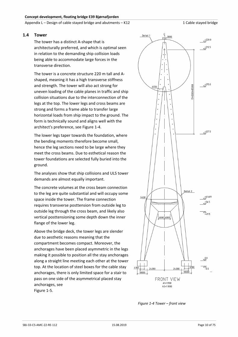
1.4 Tower
The tower has a distinct A-shape that is
architecturally preferred, and which is optimal seen
in relation to the demanding ship collision loads
being able to accommodate large forces in the
transverse direction.
The tower is a concrete structure 220 m tall and A-
shaped, meaning it has a high transverse stiffness
and strength. The tower will also act strong for
uneven loading of the cable planes in traffic and ship
collision situations due to the interconnection of the
legs at the top. The lower legs and cross beams are
strong and forms a frame able to transfer large
horizontal loads from ship impact to the ground. The
form is technically sound and aligns well with the
architect's preference, see Figure 1-4.
The lower legs taper towards the foundation, where
the bending moments therefore become small,
hence the leg sections need to be large where they
meet the cross beams. Due to esthetical reason the
tower foundations are selected fully buried into the
ground.
The analyses show that ship collisions and ULS tower
demands are almost equally important.
The concrete volumes at the cross beam connection
to the leg are quite substantial and will occupy some
space inside the tower. The frame connection
requires transverse posttension from outside leg to
outside leg through the cross beam, and likely also
vertical posttensioning some depth down the inner
flange of the lower leg.
Above the bridge deck, the tower legs are slender
due to aesthetic reasons meaning that the
compartment becomes compact. Moreover, the
anchorages have been placed asymmetric in the legs
making it possible to position all the stay anchorages
along a straight line meeting each other at the tower
top. At the location of steel boxes for the cable stay
anchorages, there is only limited space for a stair to
pass on one side of the asymmetrical placed stay
anchorages, see
Figure 1-5.
Figure 1-4 Tower – front view

Concept development, floating bridge E39 Bjørnafjorden
Appendix L – Design of cable stayed bridge and abutments – K12 1 Cable stayed bridge
SBJ-33-C5-AMC-22-RE-112 15.08.2019 Page 11 of 75
Due to esthetical reason the tower stay anchorages are spaced
every 5.0 m, which is more than normal, i.e. it will be easy to
adopt the cable stay forces in the steel anchor structure and
transfer it to the concrete by means of shear connectors. This will
furthermore make the stay tensioning within the tower easier.
Figure 1-5 Tower – plan section through leg at stay anchorages
At the tower top, the two legs are merged and taper further towards the top. Here the space
conditions will be constrained to keep the slender impression. Normal concrete strength C40 – C50
will suffice, and the reinforcement quantity will be normal, 150 – 200 kg/m³.
The concrete tower structure of the cable stayed bridge can be seen to be well documented standard
products built before and therefore not adding significant risks to the project.
A visualisation of the cable stayed bridge can be seen in Figure 1-6 where the tower forms almost a
lighthouse landmark.
Figure 1-6 Cable stayed bridge with the tower forming a light house landmark
1.5 Bridge deck
1.5.1 Bridge deck – steel
For the selected concept, the steel bridge deck starts 140 m from the tower into the side span and
continues throughout the entire main span of 380 m until 20 m from the first pontoon pier A3, see
also Figure 1-1. The length of the steel deck then becomes 500 m with an average total girder weight
of 17.0 t/m. The steel deck is much lighter than the concrete deck and therefore a natural choice for
the main span. In the side span the steel deck has been chosen going 140 m into the span due to high
bending moments round strong axis from ship impact in the tower region and furthermore to span
over the water to the first pier A1E.

Concept development, floating bridge E39 Bjørnafjorden
Appendix L – Design of cable stayed bridge and abutments – K12 1 Cable stayed bridge
SBJ-33-C5-AMC-22-RE-112 15.08.2019 Page 12 of 75
An alternative layout of the bridge deck has already been mentioned and described briefly in section
1.2 considering extending the concrete girder to the entire length of the side span in the aim of
optimising the design further. This option has become possible as the ship collision forces have
decreased reaching a maximum level of 3300 MNm round strong axis at tower position.
A cross section of the bridge girder can be seen in Figure 1-7 where the steel girder is optimised for
the cable stayed bridge having a reduced girder depth of 3.5 m instead of 4.0 m as for the floating
bridge. The cross section is more aerodynamically shaped with wind noses and wider to
accommodate the cable anchorages. A wider deck is also beneficial withstanding the large moments
round strong axis from ALS ship collision as well as normal ULS. The outer vertical web plate from the
floating bridge spaced 27.0 m can be found unchanged in the cross section layout for the cable stay
bridge, now supporting the stay anchorages.
Figure 1-7 Steel bridge girder – cross section, longitudinal steel
The deck plate varies from a minimum thickness of 16 mm up to 20 mm when approaching the tower
from both side- and main span and again when approaching the first floating bridge pier 3. Fatigue
calculations carried out documents that a deck plate of min 16 mm will be necessary instead of the
more conventional 14 mm due to truck loading. The trapezoidal stiffeners underneath the deck plate
vary from minimum 8 to 10 mm, again to accommodate the fatigue requirements.
The bottom plate and the inclined web plates varies from a minimum thickness of 12 mm up to 20
mm near the tower and again when approaching the first floating bridge pier 3. For the bottom plate
the principles using bulb stiffeners are chosen due to preference of the floating bridge.
The cross section layout is further described in section 3.3.1. and Figure 1-8 shows the layout of the
transverse truss diaphragm with a spacing in the bridge line of 4.0 m. The transverse truss solution
has been selected as it in general is lighter than a full plated diaphragm solution.
Figure 1-8 Steel bridge girder – layout of transverse truss diaphragm spaced 4.0 m

Concept development, floating bridge E39 Bjørnafjorden
Appendix L – Design of cable stayed bridge and abutments – K12 1 Cable stayed bridge
SBJ-33-C5-AMC-22-RE-112 15.08.2019 Page 13 of 75
The deck constitutes an important part of the cable stayed bridge which is a well-documented
standard product not adding a significant risk to the project. The steel girder quantity becomes 8600
t equal to an average total girder weight of 17.0 t/m. The steel bridge deck constitutes 40-45% of the
total bridge cost.
1.5.2 Bridge deck – concrete
The concrete bridge deck is fully fixed in the abutment and to the steel deck. The total length for the
concrete deck is 260 m. In the distance of 110 m closest to the tower, stay cables are anchored in the
cross section. The distance between the stay cable planes is chosen to be 28.0 m. The width of the
cross section is therefore selected to 29.5 m giving sufficient space for the stay cable anchorages.
It is possible to reduce the cross section width between the abutment and the cable stayed bridge.
However, this will also be an aesthetically evaluation.
The cross section height is 3.5 m, somewhat optimal for a span length of 55 m and upwards. The
thickness of the bottom slab is 280 mm while the top slab is 300 mm and web thicknesses are 450
mm. Diaphragms are used at each pier and at each stay cable anchor. The diaphragm thickness is
3000 mm at piers and 500 mm at stay cable anchorages. 24 prestressing tendons with breaking load
5300 kN are used above the piers and 12 prestressing tendons within the field. Normal
reinforcement amount of 160 kg/m3 concrete is used. A cross section of the box girder can be seen in
Figure 1-9.
A wide box section type is chosen due to the following reasons:
The cross section shape is similar to the cross section layout within the main span
Forces from the stay cables can easily be incorporated in the cross section
The bridge deck is subjected to high bending moment about strong axis from ship collision which
becomes favourable having large concrete areas close to the outer edges of the cross section
Small reinforcement amount is needed in the transverse direction due to the cross section shape
Construction of the bridge girder for the selected concept can e.g. be done by:
Use of MSS (movable scaffolding system, spanning from pier to pier) for concrete cross section
typical max 70-75 m between piers/temporary supports
Incremental launching (ILM) with typical max 50-55 m between piers/temporary supports
Concrete cast in place with scaffolding supported on ground
Figure 1-9 Concrete box girder - cross section

Concept development, floating bridge E39 Bjørnafjorden
Appendix L – Design of cable stayed bridge and abutments – K12 1 Cable stayed bridge
SBJ-33-C5-AMC-22-RE-112 15.08.2019 Page 14 of 75
The concrete girder of the cable stayed bridge can be seen to consist of well documented standard
products not adding significant risks to the project.
1.5.3 Bridge girder joint
The joint between the steel bridge girder and the concrete girder is located 135 m from the tower
near the first side span pier. Here the strong axis bending moment due to ship collision is reduced to
50% of the maximum moment at the tower or less and the connection by means of post-tensioning
cables and high-strength bars will then be less demanding.
The joint will be based on the same principles as used for the Pont de Normandie (France). The
posttensioning cables will be anchored a certain distance from the joint inside the steel box and be
cast in the concrete deck. Along the circumference of the steel box a number of high strength bars
will be installed at tight spacings.
The connection could be established in two steps. First the steel box and the concrete deck is
brought near to each other and partially stressed. In this locked situation a stich joint concrete
(grout) is cast ensuring the complete connection of the two bridge deck types. After curing of the
stich joint, the cables and bars are fully tensioned.
The bridge girder joint of the cable stayed bridge is not a standard solution within cable stayed
bridges but is however well-known technology from other large cable stayed bridges as the Pont de
Normandie in France and the Russky Bridge in Russia, both well known within the Joint Venture. The
joint will therefore not add any significant risks to the project.
1.6 Cable stays
The cable stays of the bridge are multi-strand type with 31–67 no of strands, each 15.7 mm dia.
having an ultimate breaking strength of 1860 MPa. The 31 strand cable thus has a breaking strength
of 8.6 MN, and the 67 strand cable 18.6 MN.
The stays are arranged in 4 fans, each having 18 cables, the shortest nearest to the tower are
subjected to the lowest loads, whereas the flattest outermost cables have the highest loads. The
cables outbalance each other horizontally at the tower anchorage, however minor deviations are
acceptable, and forces may be slightly redistributed. Hence, the cables can be grouped and totally 6
different cable sizes are presented here.
The cable stays stressing ends are anchored in the steel boxes in the tower legs making the
tensioning process easy, whereas their passive ends are anchored at the bottom end of steel tubes
sticking trough the verges of the bridge deck.
The cable sizes are determined by the maximum ULS load that may occur. ULS1 (permanent load
dominant), the ULS2 (traffic load dominant) and ULS3 (wind/wave dominant) lead almost to the
same loads, whereas ship collision not becomes critical. All load effects are comparable with those of
other cable stayed bridges, except wave load effects to the longest stays nearest to axis 3. In
appendix I also the cable capacity for fatigue is checked and found to be very high. The main
contributors to fatigue are traffic and tide. Traffic contributes most to fatigue near the tower while
tide contributes most to fatigue in the northern bridge end in vicinity of the first floating bridge
pontoon in axis 3.
The stays are documented by a mix of analyses results. New results from global floating bridge
analyses (Orcaflex/LS-DYNA) and RM-Bridge have been combined, and a separate SOFISTIK model of
the cable stayed bridge has been used for comparison and check.
Concept development, floating bridge E39 Bjørnafjorden
Appendix L – Design of cable stayed bridge and abutments – K12 1 Cable stayed bridge
SBJ-33-C5-AMC-22-RE-112 15.08.2019 Page 15 of 75
The load effects in each cable are tabulated in the stay cable drawing. Further documentation is
enclosed in section 3.5.
The longest stays will require a damping system to be installed as also indicated on the drawings.
Additional damping might be necessary for the longest stays if snow is expected to accumulate on
the stays. For reference, the Øresund Bridge has additional damping installed safeguarding against
stay oscillations due to possible snow accumulation. The above topic is well known by the Joint
Venture.
The stays constitute an important part of the cable stayed bridge, however, they are well-
documented standard products that are not supposed to add a significant risk to the project. The
total quantity is 1000 tonnes approximately and constitutes about 15 % of the total cable stayed
bridge cost. The construction is standard strand-by-strand installation.
1.7 Side span piers
The concrete piers are rectangular, 10–11 m wide and 2.0–2.5 m thick. The pier foundations are also
rectangular with the below shown sizes all buried into the ground. The height varies in accordance
with the terrain, and the tallest pier is about 56 m. The piers will be governed by the ship collision
effects (ALS) and forces from the load combination ULS3. For the longest pier 1-E the load situation
with wind on free standing pier is slightly governing for the foundation size and the reinforcement in
the bottom of the pier. Since the heights are much shorter for the other piers (1-D is approximately
42 m high), the construction stages seem not to be governing for them.
The pier foundations will be cast directly on rock or blasted rock with a concrete scaling. All the
foundations are placed above water but buried into the ground due to esthetical reason. The piers
can be cast e.g. with jump- or slip form.
The foundation sizes:
1-A, 1-B, 1-C WidthxDepthxHeight: 7x15x3 m
1-D WidthxDepthxHeight: 7x18x3 m
1-E WidthxDepthxHeight: 8x18x3 m
1.8 Ship collision
Ship collision is a governing load situation and an important factor for the cable stayed bridge design.
The K11 alternative in the previous phase had the bridge deck and tower disintegrated transversely,
with the purpose to distribute the elastic response as wide as possible. For this phase, a tight fit
between bridge deck and tower has been selected. Thereby, the ship collision effect is more direct
leading to high loads, but as the tower have such high strength, it becomes an appropriate design
methodology.
The A-tower has a very robust lower frame that initially designed resisting a load of 50 MN, but
actual load is found to be 35 MN. This force between the horizontal bearing on the side of the bridge
deck and the inner side of the tower is slightly affected by the stiffness of the side-span piers.
The A-shape and wide distance between the tower leg foundations makes it very stable against ship
collision, and the tower as such is far from being overloaded or overturned due to ship impact.
The strong axis bending moment of the bridge deck at the tower is 3300 MNm and is the most
dominant ship collision effect. The effect to all the structures can more or less relate to this high
moment. With the rigid approach, the south abutment is no longer subjected to severe moments as
in the previous phase of the project.

Concept development, floating bridge E39 Bjørnafjorden
Appendix L – Design of cable stayed bridge and abutments – K12 1 Cable stayed bridge
SBJ-33-C5-AMC-22-RE-112 15.08.2019 Page 16 of 75
For ship collision to the pontoon axis 3 the bridge deck also experiences large bending moments at
this end (and further into the floating bridge).
Torsion and shear effects are small, however, the shear between the tower and the nearest on-shore
pier is high.
Ship collision is not critical for the stays and the tower legs above bridge deck.
1.9 Tidal variation of axis 3 support
The nearness of the axis 3 support subjected to vertical tidal movements has been a concern. The
pontoon stiffness is however much higher than the cable stiffness, hence the cable stayed bridge will
follow the deformations of the pontoon, basically.
However, the effect in terms of weak axis moments in the bridge deck, and additional cable loads for
the outermost flattest cables, have shown to be only moderate. The cable forces will be rather
immune for such design changes. This shows that the proposed system with 20 m between the no 18
stay anchorage and axis 3, and the inclination angle of 220 seems a feasible and appropriate solution.
Even an extension of the distance between the outermost cable and the first pontoon support is not
foreseen becoming a challenge. It has been evaluated to increase the distance by further 20 m
without any notable impact to the design.
The outermost stay has furthermore been examined for fatigue due to tidal and wave motions
showing sufficient capacity, please refer to Appendix I.
1.10 Construction
The construction of the cable stayed bridge contain working processes that are well known and
straight forward. The bridge is situated on-shore except that a temporary bridge or embankment fill
is required to provide access to Svarvahelleholmen. Due to limited space on the island, probably
floating barges around the tower foot will be required for concrete works.
The works start with access roads and ground works for the south abutment, tower foundation and
side span piers, with access roads between these sites. After preparation of the ground, the
foundations can be casted. Jump formwork is then used for construction of the lower tower legs and
piers. Temporary strutting between the tower legs is required due to their inclination.
After completion of piers, span-by-span construction of the concrete side spans can begin. An
overhung or underhung moving scaffolding system can be used, and the scaffolding system is shifted
along the bridge span by span, with in situ concrete works. The bridge deck is cast monolithic to the
pier tops (no bearings). The bridge structure is longitudinally post-tensioned as necessary for the
construction stage. Full tensioning can await completion of the concrete works.
To reduce thermal constraint, it may be necessary to cast the stich joint connection to the abutment
at a late stage after creep and shrinkage effects, and at neutral temperature.
The tower cross beam is cast in-situ supported by temporary scaffolding (truss) spanning between
the legs. Hereafter the tower legs are cast by climbing formwork, alternatively by slip forming. Steel
boxes for the stay anchorages are placed one by one while the concrete progress towards the top.
Where the two legs join at level +175, the jump-form is shifted to a full-width form, used to the very
top of the tower at +220.
Once constructed, the steel bridge "tower segment" is shifted in between the tower legs from the
main span side. Then balanced erection of steel deck segments, 20 m long, is carried out. The water

Concept development, floating bridge E39 Bjørnafjorden
Appendix L – Design of cable stayed bridge and abutments – K12 1 Cable stayed bridge
SBJ-33-C5-AMC-22-RE-112 15.08.2019 Page 17 of 75
between the Svarvahelleholmen and Reksteren allows the side-span segments to be lifted off the
barges also to this side, i.e. no steel element need to be transported on the ground.
When a steel segment has been lifted by the derrick crane and the joint is partly welded, the stays
are installed. The cable is formed by individual strands that are pulled from the top and anchored at
the bottom. When the stays are complete, and the steel segment joint is welded, the derrick crane
can be moved further out ready for the next section. The segment installation continues until the
segment towards the concrete spans is in place. The joint will be with in-situ stich concrete or grout,
followed by tensioning of the longitudinal cables and bolts going through the joint.
The cycle of erecting steel segments is estimated to be in the range of 10-14 calendar days. It can
however be done in parallel both sides for the first 2*7 segments.
The above erection schedule implies that the cable stayed bridge shall stay the winter fully erected
without connection to the floating bridge. This situation is analysed and found not to be critical.
The bridge finishing works, pavement, barriers, bearings etc. are finally installed. A more detailed
description of the different construction steps is given in appendix N Construction and marine
operations.

Concept development, floating bridge E39 Bjørnafjorden
Appendix L – Design of cable stayed bridge and abutments – K12 2 Abutments
SBJ-33-C5-AMC-22-RE-112 15.08.2019 Page 18 of 75
2 Abutments
2.1 General arrangement
The bridge is without expansion joints, and the bridge girder is fixed to the abutments both in south
and north. This solution induces large forces to the abutments, and especially in north where the
abutment was found to need about 2000 m2 area, 52 m x 38 m, and a height of about 10 m to
contain the necessary amount of ballast to achieve a weight of 60.000 ton. The weight/area is based
on stability by weight only and a coefficient of friction 1.0 for concrete poured on cleaned rock
surface.
In north the steel girder for the floating bridge is widened from 27 m to 36 m to suit the abutment,
and large prestressing tendons are used in the steel/concrete connection.
In south the concrete approach bridge continues as the upper part of the abutment and is casted
monolithically to the walls.
2.2 Analyses
The governing loading on the abutments is bending moment about the vertical axis, coming from
environmental loads or ship impact. Below is summarised the max/min loading N is axial load in the
bridge, positive sign is tension. Mz moment about the vertical axis, and My moment about the
horizontal axis, positive sign is tension upper face. Units MN and MNm.
Table 2-1 Abutment north and south – design loads for ULS and ship collision
Nmax Nmin Mzmax Mzmin Mymax Mymin
Ship imp. north 74 -77 5876 -5838 341 152
ULS 3 north 63 -55 2439 -2680 1196 -370
Ship imp. south 74 -75 606 -770 17 -15
ULS 3 south 69 -83 24 -24 128 71
Torsional moment and shear forces are not shown as they have a minor influence on the design.
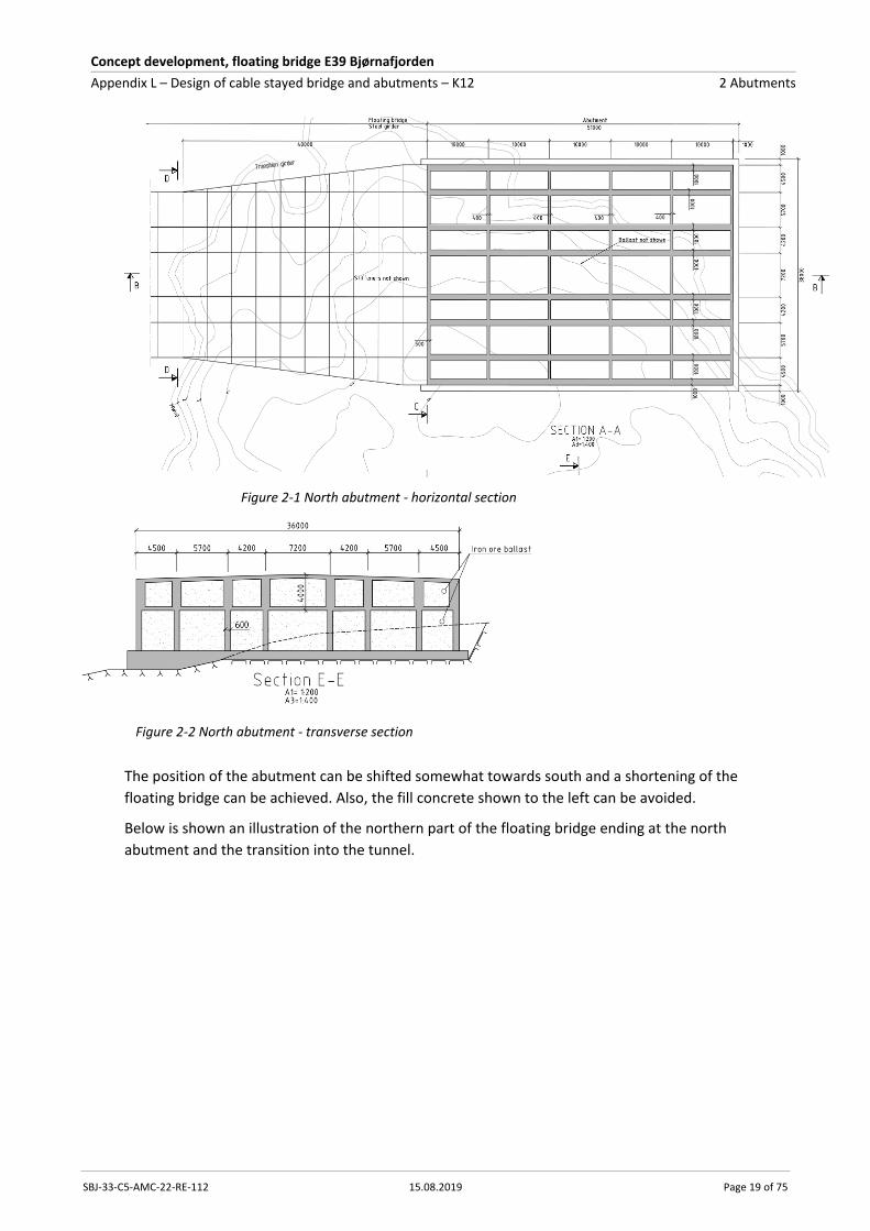
2.3 North abutment
At the north abutment the road level is at elevation 11.6 m, and the area is chosen such that the
entire abutment is above the water level. Ship impact governs the size of the abutment. With an
abutment size of 50 m x 36 m, footprint 52 m x 38 m, the necessary height with iron ore ballast is
around 10.0 m. Rock anchors can decrease the area or height but is not used at this stage.
A reduction of the ship impact forces will reduce the footprint/height, or olivine/gravel can be used
as ballast instead.
The abutment is a large box structure with longitudinal walls lining up with the longitudinal
bulkheads in the steel floating bridge. 150 nos. longitudinal prestressing tendons secure the
connection to the bridge.
Concept development, floating bridge E39 Bjørnafjorden
Appendix L – Design of cable stayed bridge and abutments – K12 2 Abutments
SBJ-33-C5-AMC-22-RE-112 15.08.2019 Page 19 of 75
Figure 2-1 North abutment - horizontal section
Figure 2-2 North abutment - transverse section
The position of the abutment can be shifted somewhat towards south and a shortening of the
floating bridge can be achieved. Also, the fill concrete shown to the left can be avoided.
Below is shown an illustration of the northern part of the floating bridge ending at the north
abutment and the transition into the tunnel.
Concept development, floating bridge E39 Bjørnafjorden
Appendix L – Design of cable stayed bridge and abutments – K12 2 Abutments
SBJ-33-C5-AMC-22-RE-112 15.08.2019 Page 20 of 75
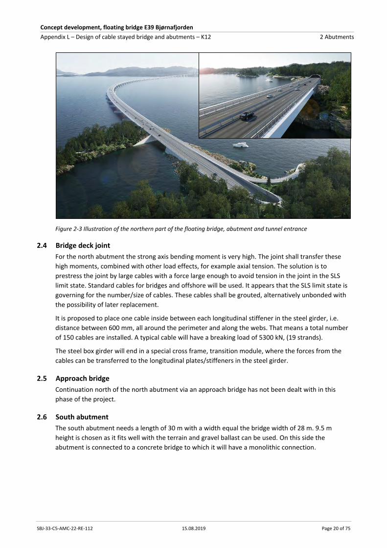
Figure 2-3 Illustration of the northern part of the floating bridge, abutment and tunnel entrance
2.4 Bridge deck joint
For the north abutment the strong axis bending moment is very high. The joint shall transfer these
high moments, combined with other load effects, for example axial tension. The solution is to
prestress the joint by large cables with a force large enough to avoid tension in the joint in the SLS
limit state. Standard cables for bridges and offshore will be used. It appears that the SLS limit state is
governing for the number/size of cables. These cables shall be grouted, alternatively unbonded with
the possibility of later replacement.
It is proposed to place one cable inside between each longitudinal stiffener in the steel girder, i.e.
distance between 600 mm, all around the perimeter and along the webs. That means a total number
of 150 cables are installed. A typical cable will have a breaking load of 5300 kN, (19 strands).
The steel box girder will end in a special cross frame, transition module, where the forces from the
cables can be transferred to the longitudinal plates/stiffeners in the steel girder.
2.5 Approach bridge
Continuation north of the north abutment via an approach bridge has not been dealt with in this
phase of the project.
2.6 South abutment
The south abutment needs a length of 30 m with a width equal the bridge width of 28 m. 9.5 m
height is chosen as it fits well with the terrain and gravel ballast can be used. On this side the
abutment is connected to a concrete bridge to which it will have a monolithic connection.

Concept development, floating bridge E39 Bjørnafjorden
Appendix L – Design of cable stayed bridge and abutments – K12 2 Abutments
SBJ-33-C5-AMC-22-RE-112 15.08.2019 Page 21 of 75
Figure 2-4 South abutment - horizontal section
Figure 2-5 South abutment - transverse section
2.7 Ship collision
The ship collision is a very demanding load effect for the north abutment. The collision to the floating
bridge leads to high strong axis bending moments, for which the gravity structure and connection
shall be designed. The ship collision loads have varied throughout the project period and more
refined analyses now show a strong bending moment of 5900 MNm. The fixity of the bridge
enhances the bending moments compared with those of the floating bridge in general. The widening
of the bridge deck over some length near the abutment leads to sufficient increase in capacity,
however, the increased stiffness will again give increased bending moments.
Introduction of a Vessel Traffic Management System in the area is being considered which probably
will result in less forces from ship impact.

Concept development, floating bridge E39 Bjørnafjorden
Appendix L – Design of cable stayed bridge and abutments – K12 2 Abutments
SBJ-33-C5-AMC-22-RE-112 15.08.2019 Page 22 of 75
2.8 Construction
Both abutments shall be built at solid rock, and it is expected to find it right below the ground
surface. All work will be above water. In south about 2500 m3 rock shall be blasted for levelling off
the bottom slab, and the double volume in north. A minimum 1 m thick bottom slab will be casted
directly on rock forming the base for the abutment. The construction work should be quite
straightforward, but there are large areas, 7000 m² and 14000 m2 formwork in south and north
respectively and concrete volumes of 4000 m3 and 9000 m³. Both abutments shall be filled with solid
ballast, in south 4000 m3 gravel and in north 11000 m3 iron ore.
In south the concrete bridge side span will be cast monolithically to the abutment. In north the
floating bridge steel girder shall be attached to the abutment by 150 nos. prestressing tendons. The
ducts will be placed in the walls and slabs in the abutment, and the structures casted until about 1.0
m from the position for the steel bridge. When the steel girder is in position the gap will be cast and
the strands installed for anchorage in the steel bridge. The tendons will be stressed from the north
side of the abutment.

Concept development, floating bridge E39 Bjørnafjorden
Appendix L – Design of cable stayed bridge and abutments – K12 3 Cable stayed bridge calculations
SBJ-33-C5-AMC-22-RE-112 15.08.2019 Page 23 of 75
3 Cable stayed bridge calculations
3.1 Introduction
The analyses that support the cable stayed bridge (and abutment) design are combinations from
different analyses:
• Global, dynamic wind and wave analyses of floating bridge (ORCAFLEX)
• Global dynamic analyses of ship collision to floating bridge (LS-DYNA)
• Permanent load, wind and traffic (RM Bridge)
• A local dynamic wind analysis of critical construction stages for the cable stayed bridge
(Novaframe)
• Local cable stayed bridge (SOFISTIK) used for verification
The design checks for permanent stage for the different structural elements are based on forces
from the global analysis. These analyses are documented in separate Appendices, primarily F, G and
J. The load combinations used are envelope based. For dynamic loads such as dynamic wind and
waves, separate time history analyses are done for wind and waves for a one hour storm (one seed).
The time history of the results, e.g. section forces, are then added linearly, and the maximum section
force/moment combined with the other five coexisting section forces/moments at the time step is
defining the envelope. This methodology is accurate enough to justify the technical feasibility and
estimate the quantities.
The structural design capacities are checked for the following design forces:
ULS forces during service: Maximum concurrent time history forces and moments from
environmental load realisations load combined with static loads. In ULS2 traffic load is the
dominating variable load combined with 1 year return period environmental loads. In ULS3 100
year return period environmental loads are the dominating variable load (“ULS2_ULS3” in
capacity diagrams).
ALS Ship collision: Maximum concurrent time history forces and moments from the different ship
impact simulations for deck house and pontoon impacts combined with permanent static loads
(“ALS-ship-deckh_pont” in capacity diagrams)
ULS constructions stages: Frequency domain wind results for constructions stages a, b and c load
combined with permanent static loads. (“CS_abc” in capacity diagrams)
The designed cross sections are generally chosen as equal to those in the global analysis models.
In the subchapters below, the design of critical structural components and sections is outlined. For
more detailed documentation of the design of concrete sections, refence is made Enclosure L1 for
plots, detailed listings and comparative plots for different load actions and bridge concepts. The
following six concrete sections are evaluated:
Table 3-1 FE-model, structural parts and concrete sections
No Structural part Section No. of sections
1 Lower tower legs Connection to foundation 2 (east and west)
2 Lower tower legs Connection to cross beam 2 (east and west)
3 Tower cross beam Connection to tower legs 2 (east and west)
4 Side piers Connection to foundation 5 (5 piers)
5 Girder concrete side span Mid spans 5 (between all side piers)
6 Girder concrete side span Supports 5 (at all side piers)

Concept development, floating bridge E39 Bjørnafjorden
Appendix L – Design of cable stayed bridge and abutments – K12 3 Cable stayed bridge calculations
SBJ-33-C5-AMC-22-RE-112 15.08.2019 Page 24 of 75
The design verification of the steel box girder is done within the global FE-model itself by
postprocessing routines using the same principles as for the floating bridge. The design verification is
done using two different cross section types H1 and H2 with different plate thicknesses of the skin
plates. General stresses are reported at corner points of the box girder along the box girder with 10.0
m spacing. The design verification is carried out using the reduced width method within Eurocodes.
3.2 Tower
The tower design will be driven by wind loads on the free-standing tower during construction, ship
collision forces and maximum ULS forces during service.
Wind along the bridge on the free standing tower in construction stage is governing for the
reinforcement in lower parts of the tower. The normal force is low for the tower in this stage and
therefore have a small contribution to the capacity. (Compression force to a certain extend increase
the bending capacity)
The ship collision leads to a very high transversal force between the bridge deck and the tower legs.
Still, ULS demands and ship collision demands are almost equal.
For the tower legs from deck level and upwards, ULS loadings will be governing. For the dimensions
of the tower leg, quite conventional, these loads will not be very critical to the leg sections.
The steel anchor boxes will be subjected to the splitting cable forces, and they shall provide a tie
between the pair of cables. Shear connectors shall transfer horizontal forces not being in equilibrium
to the concrete walls. Based on comparison with similar concepts of other cable stayed bridges, it is
relatively easy to design these steel elements for the local loads that are determined by the size of
the cables.
3.2.1 Tower design
Capacity diagrams for bending-axial interaction are plotted for three critical tower sections below. A
more detailed documentation is given in Enclosure L1.
The capacity diagram for the leg sections shows that moment about transverse axis is most critical
compared to the moment around longitudinal axis. The most critical load is wind on free standing
tower in construction stage.
Minimum reinforcement for the tower is according to Eurocode simplified 1.2% of concrete area with
the used concrete and reinforcement quality. The reinforcement amounts in the diagrams are lower
or not much higher than the minimum reinforcement.
For the cross beam both wind in construction stage, ULS and loads from ship impact, ALS are
governing. Moment about the horizontal axis is governing.

Concept development, floating bridge E39 Bjørnafjorden
Appendix L – Design of cable stayed bridge and abutments – K12 3 Cable stayed bridge calculations
SBJ-33-C5-AMC-22-RE-112 15.08.2019 Page 25 of 75
Tower legs at foundation interface
Figure 3-1: Capacity diagrams. Tower legs at foundation interface. Triangle – ULS2 & ULS3, red diamond – ALS ship collision, blue square – erection situations

Concept development, floating bridge E39 Bjørnafjorden
Appendix L – Design of cable stayed bridge and abutments – K12 3 Cable stayed bridge calculations
SBJ-33-C5-AMC-22-RE-112 15.08.2019 Page 26 of 75
Tower legs at cross beam interface
Figure 3-2: Capacity diagrams. Tower legs at cross beam interface. Triangle – ULS2 & ULS3, red diamond – ALS ship collision, blue square – erection situations

Concept development, floating bridge E39 Bjørnafjorden
Appendix L – Design of cable stayed bridge and abutments – K12 3 Cable stayed bridge calculations
SBJ-33-C5-AMC-22-RE-112 15.08.2019 Page 27 of 75
Tower cross beam at tower leg interface
Figure 3-3: Capacity diagrams. Tower cross beam at tower leg interface. Triangle – ULS2 & ULS3, red diamond – ALS ship collision, blue square – erection situations
Concept development, floating bridge E39 Bjørnafjorden
Appendix L – Design of cable stayed bridge and abutments – K12 3 Cable stayed bridge calculations
SBJ-33-C5-AMC-22-RE-112 15.08.2019 Page 28 of 75
3.2.2 Tower foundation design
The foundation sizes are governed by wind forces on free standing tower during construction. The
chosen sizes are 21x10x5.5. The height of 5.5 m is chosen so the horizontal reinforcement amounts
in the cross section shall be moderate.
Following stability checks are performed for the critical load, wind during construction:
- Ground pressure is checked acc. to N400 11.2.3. Should be < 10MPa
- Gliding is checked acc. to N400 11.2.5. Torsional moment is not considered
- Overturning is checked acc. to N400 11.2.1
- Eccentricities also checked in SLS acc. to N400 11.2.2
The checks show a maximum ground pressure of 7 MPa in ULS to be the most critical check. For
design checks in permanent stage ground pressure in ULS/ALS and indirectly overturning are
checked.
The results show that in permanent stage, ship collision forces in ALS is more critical than the forces
from ULS3 (wind and wave dominant) with a maximum ground pressure of 3.1 MPa, i.e. much lower
than the ground pressure in construction stage.
Pressure less than 10 MPa on rock or on blasted rock are in most cases acceptable.
More detailed documentation is given in Enclosure L2.
3.3 Bridge deck
3.3.1 Bridge deck – steel
Layout
In general, the below FE-analyses of the steel box girder are based on the geometrical properties
stated in the following excel files:
Cross section type H1 used for the global FE-analyses, refer excel file
K12_07_designers_format, sheet "input H1"
Cross section type H2 used for the global FE-analyses, refer excel file
K12_07_designers_format, sheet "input H2"
The geometrical properties for the two cross section types H1 & H2 are shown in the below figures.
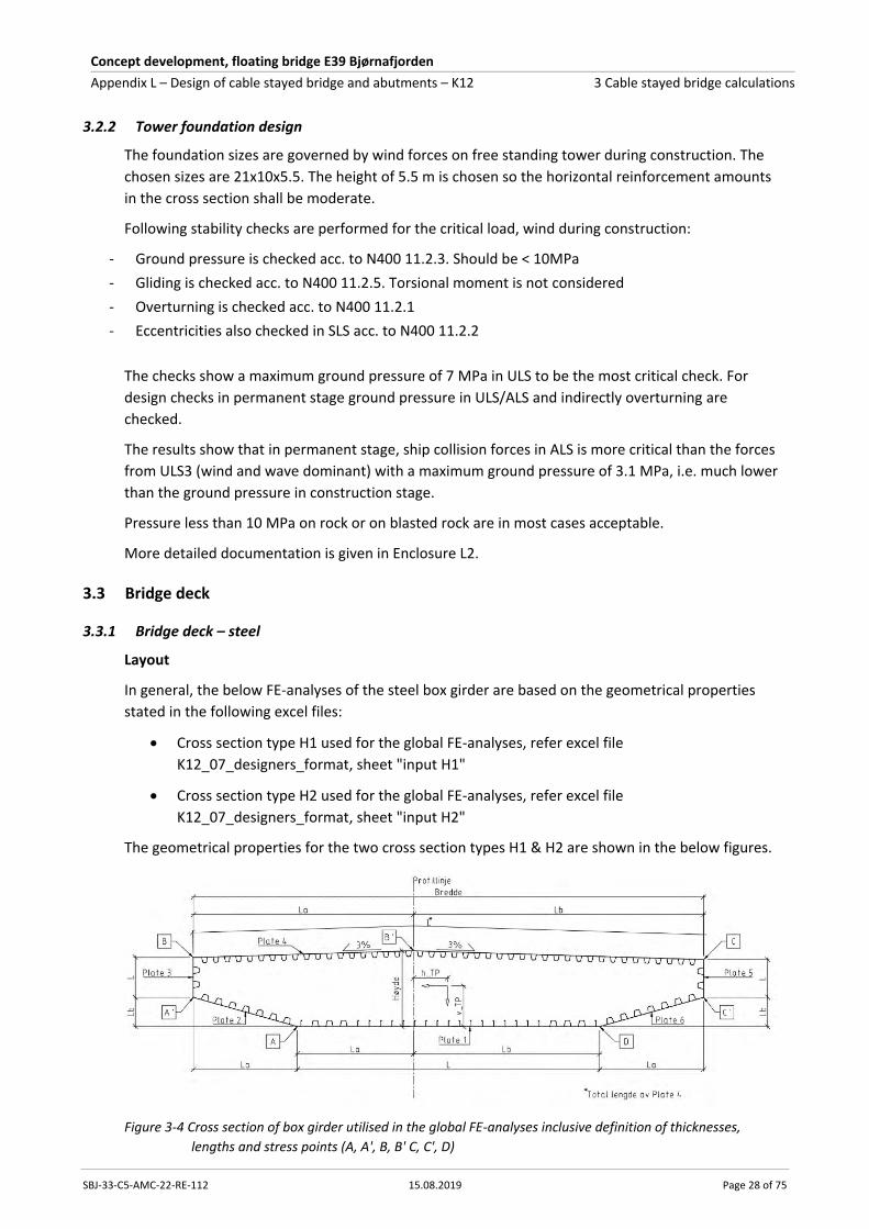
Figure 3-4 Cross section of box girder utilised in the global FE-analyses inclusive definition of thicknesses,
lengths and stress points (A, A', B, B' C, C', D)

Concept development, floating bridge E39 Bjørnafjorden
Appendix L – Design of cable stayed bridge and abutments – K12 3 Cable stayed bridge calculations
SBJ-33-C5-AMC-22-RE-112 15.08.2019 Page 29 of 75
Figure 3-5 Cross section type H1, input for global FE-analyses - refer K12_07_designers_format sheet "input H1"
Figure 3-6 Cross section type H1, input of weight and cross section properties for global FE-analyses - refer K12_07_designers_format sheet, "input H1"
From above can be seen that for box girder type H1 the cross section area of the longitudinal steel
becomes 1.297 m² equal to 10.2 t/m. For the cable stayed bridge more transverse steel is required
compared to the floating bridge as the diaphragms at the stay anchorages shall be stronger. The
transverse steel is therefore estimated to 20% of the longitudinal steel becoming 2.0 t/m. Steel for
stay anchorages, full plated diaphragm at the tower location and longitudinal diaphragms in line with
the bearings in vicinity of the tower, steel noses each side of the deck girder and steel for the
transition to the concrete box girder is estimated all in all to be approximately 4 t/m for cross section
H1 and the below mentioned H2.
Section K12_H1_rev02 Cable stayed bridge section H1 - consept K12 Revision date: 05-06-2019 @ 12:30
K12_H1_02 Last revised by:
Bredde 27 [m] fra innside plate 3 til innside plate 5 Total bredde 27.037
Høyde 3.5 [m] fra OK plate 1 til OK plate 4 Total høyde 3.512
Plate 1 Plate 2 Plate 3 Plate 4 Plate 5 Plate 6
Thickness [mm] 12 12 25 16 12 12
La [m] 6.150 5.500 - 11.650 - 5.500
Lb [m] 9.850 1.540 - 15.350 - 1.540
L [m] 16.000 5.712 1.595 13.268 1.484 5.712
Trapzoidal type K12_H1-B K12_H1-IB K12_H1-VW K12_H1-T K12_H1-VW K12_H1-IB
Trapezoidal thickness [mm] 6 6 10 8 10 6
Trapezoidal c/c [m] 0.750 0.750 Kun én stiver 0.600 Kun én stiver 0.750
Bulb type K12_H1-B_b
Width h [mm] 280
Thickness t [mm] 11
Bulb radius r [mm] 12
Bulb height c [mm] 40
Bulb width [mm] 42
Bulb c/c [m] 0.6
Tverrsnittsdata, kassetverrsnitt:
Areal: 1.297 m2
Tyngdepunkt, fra OK: 1.463 m
Tyngdepunkt, fra UK: 2.049 m
Torsjonsmotstand*: 6.629 m4
Skjærareal vertikalt*: 0.0232 m2
Skjærareal transvers*: 0.7109 m2
2. Arealmoment, svak akse*** 2.534 m4
2. Arealmoment, svak akse**** 2.534 m4
2. Arealmoment, svak akse* 2.534 m4
2. Arealmoment, sterk akse* 89.531 m4
Treghetsmoment** 1348.672 tm2/m
Masse Areal: 10.18 t/m
Masse tverrrstål: 2.00 t/m
Sum stål: 12.18 t/m
Masse rekkverk: 0.71 t/m
Masse asfalt: 4.62 t/m
Sum masse: 17.52 t/m
Contingency: 1.48 t/m
Masse brukt i analyse 19.00 t/m
*basert på fullt tverrsnitt inkl. stivere (IDEA CSS)
** inkl asfalt, rekkverk etc.
***basert på tverrsnitt redusert for shear lag i bruksgrense-/utmattingstilstand
Bøyemotstander **** basert på tverrsnitt redusert for shear lag i bruddgrensetilstand
Concept development, floating bridge E39 Bjørnafjorden
Appendix L – Design of cable stayed bridge and abutments – K12 3 Cable stayed bridge calculations
SBJ-33-C5-AMC-22-RE-112 15.08.2019 Page 30 of 75
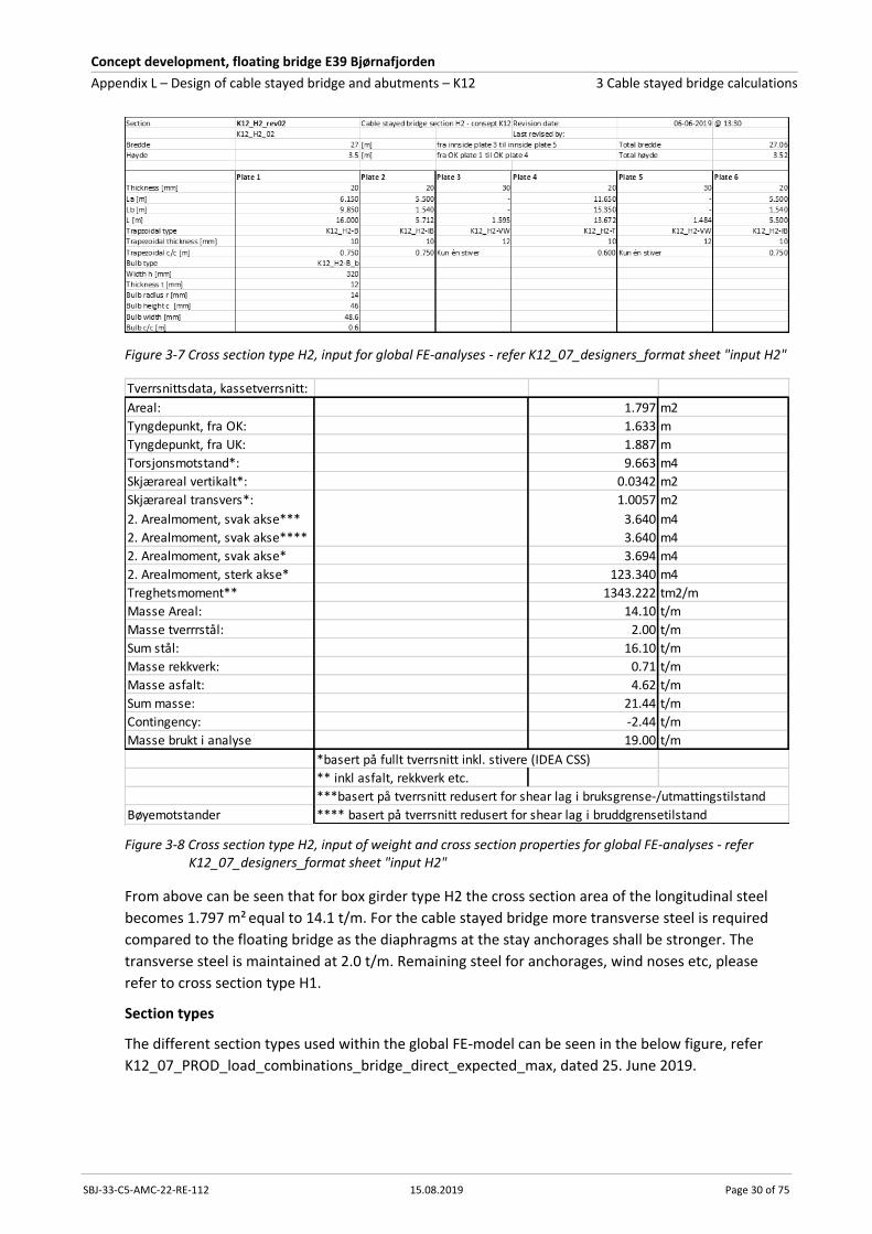
Figure 3-7 Cross section type H2, input for global FE-analyses - refer K12_07_designers_format sheet "input H2"
Figure 3-8 Cross section type H2, input of weight and cross section properties for global FE-analyses - refer K12_07_designers_format sheet "input H2"
From above can be seen that for box girder type H2 the cross section area of the longitudinal steel
becomes 1.797 m² equal to 14.1 t/m. For the cable stayed bridge more transverse steel is required
compared to the floating bridge as the diaphragms at the stay anchorages shall be stronger. The
transverse steel is maintained at 2.0 t/m. Remaining steel for anchorages, wind noses etc, please
refer to cross section type H1.
Section types
The different section types used within the global FE-model can be seen in the below figure, refer
K12_07_PROD_load_combinations_bridge_direct_expected_max, dated 25. June 2019.
Tverrsnittsdata, kassetverrsnitt:
Areal: 1.797 m2
Tyngdepunkt, fra OK: 1.633 m
Tyngdepunkt, fra UK: 1.887 m
Torsjonsmotstand*: 9.663 m4
Skjærareal vertikalt*: 0.0342 m2
Skjærareal transvers*: 1.0057 m2
2. Arealmoment, svak akse*** 3.640 m4
2. Arealmoment, svak akse**** 3.640 m4
2. Arealmoment, svak akse* 3.694 m4
2. Arealmoment, sterk akse* 123.340 m4
Treghetsmoment** 1343.222 tm2/m
Masse Areal: 14.10 t/m
Masse tverrrstål: 2.00 t/m
Sum stål: 16.10 t/m
Masse rekkverk: 0.71 t/m
Masse asfalt: 4.62 t/m
Sum masse: 21.44 t/m
Contingency: -2.44 t/m
Masse brukt i analyse 19.00 t/m
*basert på fullt tverrsnitt inkl. stivere (IDEA CSS)
** inkl asfalt, rekkverk etc.
***basert på tverrsnitt redusert for shear lag i bruksgrense-/utmattingstilstand
Bøyemotstander **** basert på tverrsnitt redusert for shear lag i bruddgrensetilstand

Concept development, floating bridge E39 Bjørnafjorden
Appendix L – Design of cable stayed bridge and abutments – K12 3 Cable stayed bridge calculations
SBJ-33-C5-AMC-22-RE-112 15.08.2019 Page 31 of 75
Figure 3-9 Section types used in global FE-analyse - ,
The chainage for the different section types of the steel girder utilised in the global FE-model can be
seen below and are found in the document K12_07_designers_format. For the cable stayed bridge
cross section type H1 and H2 is utilised as follows:
Cable stayed bridge, side span: H1, chainage 38795 – 38850, length 55.0 m
H2, chainage 38850 – 38930, length 80.0 m
Cable stayed bridge, main span: H2, chainage 38930 – 39040, length 110.0 m
H1, chainage 39040 – 39270, length 230.0 m
H2, chainage 39270 – 39295, length 25.0 m
From above, the total length of steel box girder for the cable stayed bridge becomes 495 m. Please
note that there can be small variation from above input into the global FE-models and the outcome
shown on the drawings.
Design assumptions and verification
In the global FE-model stresses are taken out in corner points of the box girder, refer Figure 3-4.
The design verification is done within the global model by postprocessing routines using the same
principles as for the floating bridge. In this section a summary will be presented showing important
section forces, von Mises stresses and for the ULS design verification the reduced width method has
been used in accordance with Eurocode, referred to as "method 2". Design verification will be done
for the ULS design situations as well as the ALS design situations (ship collision).
Design verification of ULS2 & ULS3 load situations
The below figures have been taken from SBJ-33-C5-AMC-90-RE-107_0 Appendix G Global Analyses –
Response as well as the results from K12_07_PROD_load_combinations_direct, dated 25. June 2019.
For the ULS load situations, the material factor is γm =1.1, which for steel S420 with mostly thin plates
gives fyd = 420/1.1 = 382 MPa. This value has been used as the limit in the von Mises plots shown for
the ULS2 (traffic load dominant) and ULS3 load situations (environmental load dominant).
The below 6 figures present and overview/envelopes of the section forces for ULS2 and ULS3 load
situations. The steel deck of the cable stayed bridge is located within position A1 to A3.
Concept development, floating bridge E39 Bjørnafjorden
Appendix L – Design of cable stayed bridge and abutments – K12 3 Cable stayed bridge calculations
SBJ-33-C5-AMC-22-RE-112 15.08.2019 Page 32 of 75
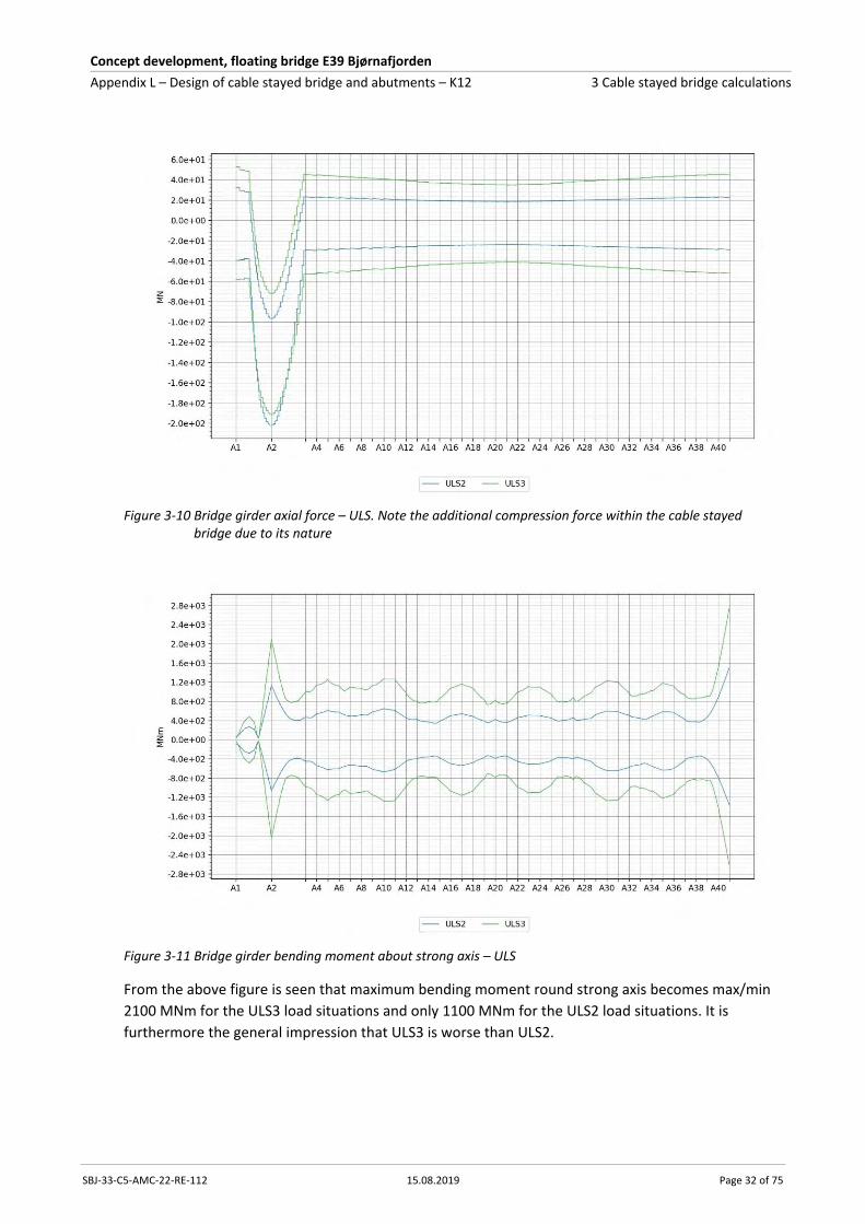
Figure 3-10 Bridge girder axial force – ULS. Note the additional compression force within the cable stayed bridge due to its nature
Figure 3-11 Bridge girder bending moment about strong axis – ULS
From the above figure is seen that maximum bending moment round strong axis becomes max/min
2100 MNm for the ULS3 load situations and only 1100 MNm for the ULS2 load situations. It is
furthermore the general impression that ULS3 is worse than ULS2.

Concept development, floating bridge E39 Bjørnafjorden
Appendix L – Design of cable stayed bridge and abutments – K12 3 Cable stayed bridge calculations
SBJ-33-C5-AMC-22-RE-112 15.08.2019 Page 33 of 75
Figure 3-12 Bridge girder bending moment about weak axis – ULS
Figure 3-13 Bridge girder torsional moment – ULS
Concept development, floating bridge E39 Bjørnafjorden
Appendix L – Design of cable stayed bridge and abutments – K12 3 Cable stayed bridge calculations
SBJ-33-C5-AMC-22-RE-112 15.08.2019 Page 34 of 75
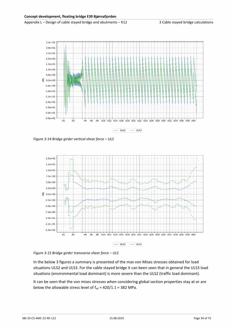
Figure 3-14 Bridge girder vertical shear force – ULS
Figure 3-15 Bridge girder transverse shear force – ULS
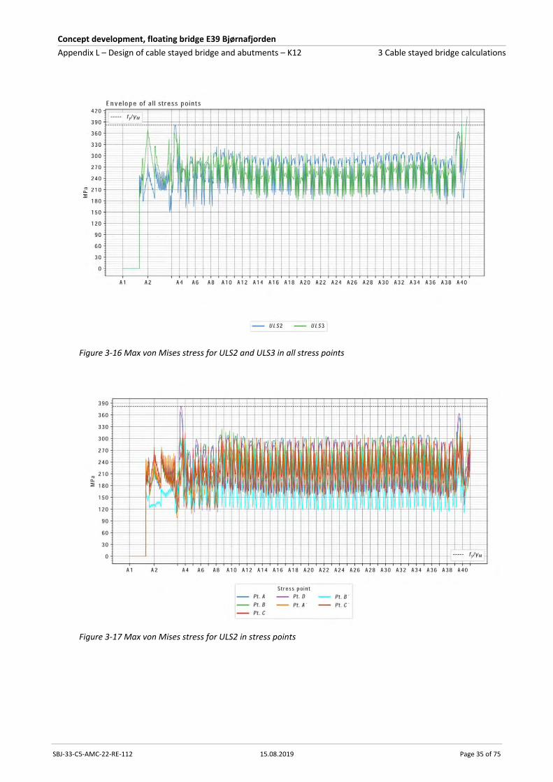
In the below 3 figures a summary is presented of the max von Mises stresses obtained for load
situations ULS2 and ULS3. For the cable stayed bridge it can been seen that in general the ULS3 load
situations (environmental load dominant) is more severe than the ULS2 (traffic load dominant).
It can be seen that the von mises stresses when considering global section properties stay at or are
below the allowable stress level of fyd = 420/1.1 = 382 MPa.
Concept development, floating bridge E39 Bjørnafjorden
Appendix L – Design of cable stayed bridge and abutments – K12 3 Cable stayed bridge calculations
SBJ-33-C5-AMC-22-RE-112 15.08.2019 Page 35 of 75
Figure 3-16 Max von Mises stress for ULS2 and ULS3 in all stress points
Figure 3-17 Max von Mises stress for ULS2 in stress points

Concept development, floating bridge E39 Bjørnafjorden
Appendix L – Design of cable stayed bridge and abutments – K12 3 Cable stayed bridge calculations
SBJ-33-C5-AMC-22-RE-112 15.08.2019 Page 36 of 75
Figure 3-18 Max von Mises stress for ULS3 in stress points
The 3 figures below present the design verification of the cable stayed bridge deck within the ULS
load situations. In general, it is seen that ULS3 load situations govern the design and the utilisation
ratio is below 1.0 unless 3 small peaks – one at the tower locations, another at the intersection
between cross section type H1/H2 and the third when approaching the first pontoon of the floating
bridge. All peaks of over utilisation are small and found acceptable at this level of design. Steel from
other locations can be moved to these areas bringing the utilisation under 1.0 without increasing the
total steel deck quantity.
Figure 3-19 Utilisation envelopes using capacity check "method 2" – ULS2 (blue), ULS3 (green)
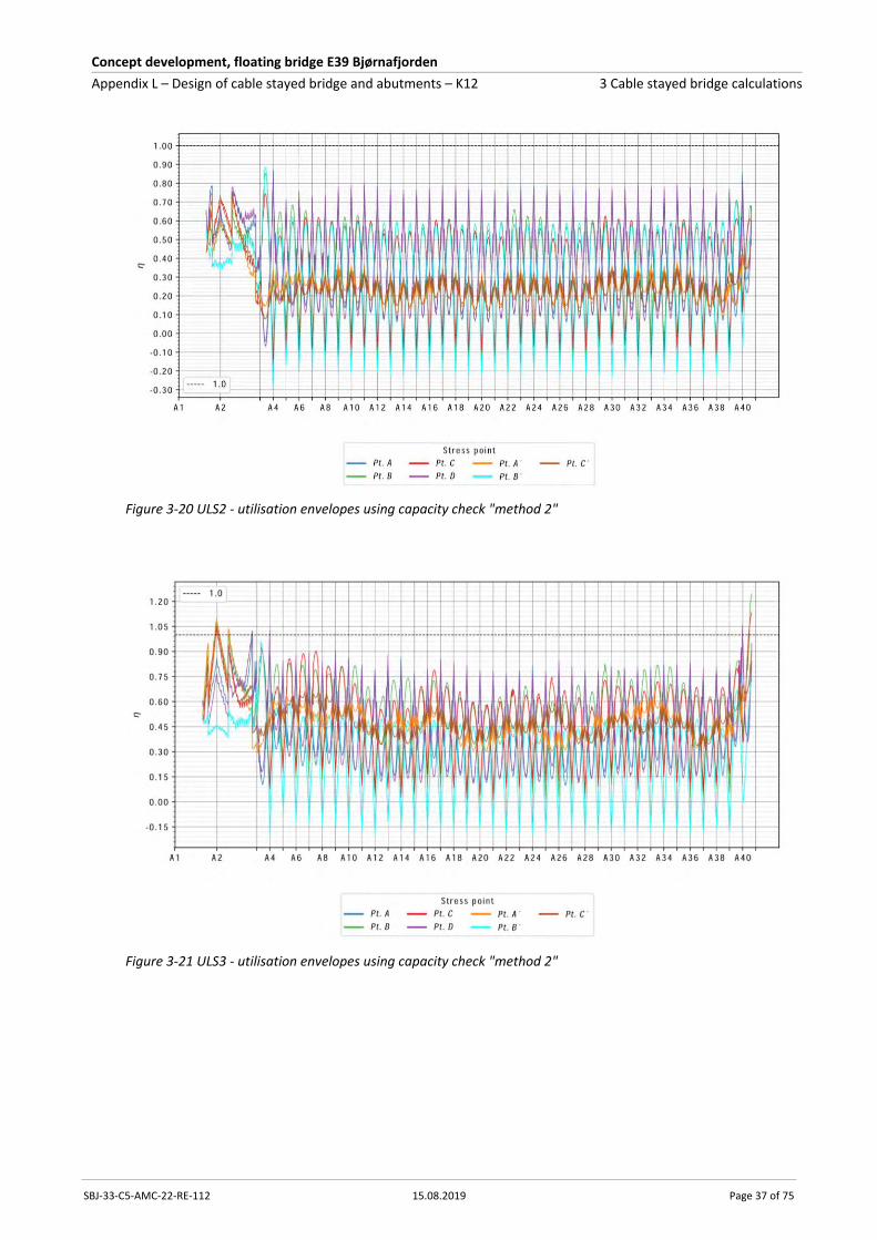
Concept development, floating bridge E39 Bjørnafjorden
Appendix L – Design of cable stayed bridge and abutments – K12 3 Cable stayed bridge calculations
SBJ-33-C5-AMC-22-RE-112 15.08.2019 Page 37 of 75
Figure 3-20 ULS2 - utilisation envelopes using capacity check "method 2"
Figure 3-21 ULS3 - utilisation envelopes using capacity check "method 2"

Concept development, floating bridge E39 Bjørnafjorden
Appendix L – Design of cable stayed bridge and abutments – K12 3 Cable stayed bridge calculations
SBJ-33-C5-AMC-22-RE-112 15.08.2019 Page 38 of 75
Design verification of ALS ship collision
The below figures have been taken from SBJ-33-C5-AMC-27-RE-110_0 Appendix J Ship collision and
ShipCollision_K12_06_revised, dated 26 June 2019, where the section forces are presented for ship
collision towards the pontoons and deck house collision towards the box girder. For the cable stayed
bridge, the overall dominant section force is the transverse shear force and the bending moment
round strong axis as presented below.
For the ALS the material factor γm =1.0. Steel S420 with mostly thin plates gives fyd = 420 MPa.
The below 4 figures present shear force and bending moment round strong axis for all ship collision
analyses carried out for "collision towards pontoon" and "collision towards bridge girder". The steel
deck of the cable stayed bridge is located within position A1-E to A3.
Figure 3-22 Ship collision towards pontoon - shear force strong axis for all analyses
Figure 3-23 Ship collision towards pontoon – bending moment round strong axis for all analyses

Concept development, floating bridge E39 Bjørnafjorden
Appendix L – Design of cable stayed bridge and abutments – K12 3 Cable stayed bridge calculations
SBJ-33-C5-AMC-22-RE-112 15.08.2019 Page 39 of 75
Figure 3-24 Ship collision towards bridge girder – shear force strong axis for all analyses
Figure 3-25 Ship collision towards bridge girder – bending moment round strong axis for all analyses
To present a design verification of all the above analyses carried out becomes too comprehensive here and therefore a summary will be presented in the 5 figures presented below where all results are envelopes and summaries of the ship collision analyses carried out.
Figure 3-26 Axial force envelopes for the bridge girder, note the additional compression force within
the cable stayed bridge due to its nature

Concept development, floating bridge E39 Bjørnafjorden
Appendix L – Design of cable stayed bridge and abutments – K12 3 Cable stayed bridge calculations
SBJ-33-C5-AMC-22-RE-112 15.08.2019 Page 40 of 75
Figure 3-27 Strong-axis shear force envelopes for the bridge girder
Figure 3-28 Strong-axis bending moment envelopes for the bridge girder
From the above figure can be seen that deck house collision in general is worse that the pontoon collision, which is also applicable for the cable stayed bridge. The maximum bending moment round strong axis becomes 3300 MNm for deck house collision and 2800 MNm for pontoon collision.
Figure 3-29 Weak-axis bending moment envelopes for the bridge girder

Concept development, floating bridge E39 Bjørnafjorden
Appendix L – Design of cable stayed bridge and abutments – K12 3 Cable stayed bridge calculations
SBJ-33-C5-AMC-22-RE-112 15.08.2019 Page 41 of 75
Figure 3-30 Envelopes of von Mises stress for the K12_06 bridge. Lines represent stresses, dots show
the simulated impact locations
The envelope of von mises stresses in the bridge girder are shown in Figure 3-30. The response is
almost within the elastic range for the cable stayed bridge, see A1-E to A3 which is judged to fully
acceptable for the design verification of the ALS load situations at this stage of the project. Please
furthermore note that a full design verification using the reduced width method has not
implemented for the ALS design situations. However, based on results from the ULS analyses, it can
be expected that the utilisation will increase by approximately 10% when considering the full design
verification using reduced width method (method 2). For the ALS ship collision this over utilisation is
however found acceptable at this stage of the design.
3.3.2 Bridge deck – concrete
Capacity diagrams for bending-axial interaction are plotted for design forces at the side span support
axes below. The reinforcement and prestressing amounts are chosen so that capacities are fulfilled
for the different sections and load situations. It is possible, without getting any high reinforcement
amounts or congestion problems, to increase the capacity considerably. More detailed
documentation is given in enclosure L1.
The capacity diagram for the section shows that moment about strong axis is most critical compared to the moment about weak axis. The most critical load is ship impact in ALS.
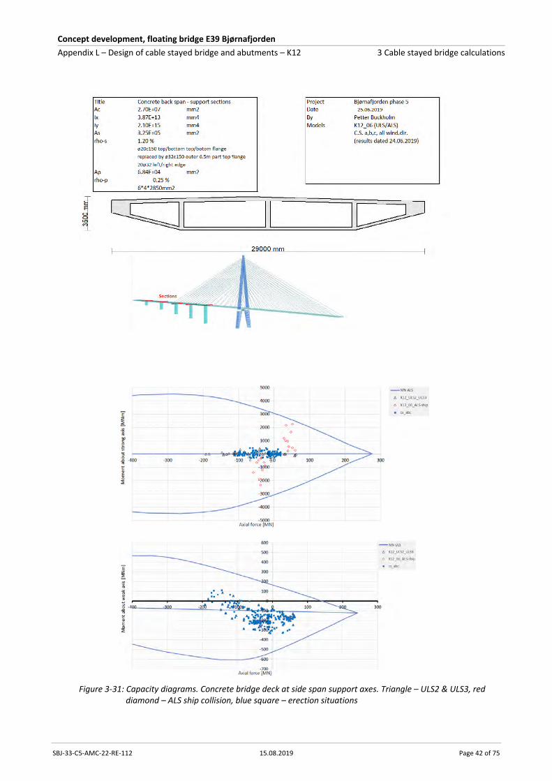
Concept development, floating bridge E39 Bjørnafjorden
Appendix L – Design of cable stayed bridge and abutments – K12 3 Cable stayed bridge calculations
SBJ-33-C5-AMC-22-RE-112 15.08.2019 Page 42 of 75
Figure 3-31: Capacity diagrams. Concrete bridge deck at side span support axes. Triangle – ULS2 & ULS3, red diamond – ALS ship collision, blue square – erection situations
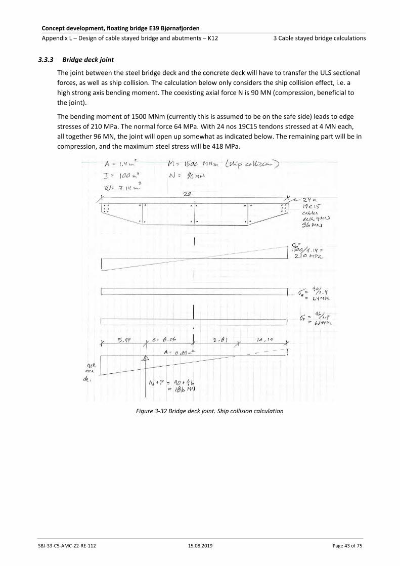
Concept development, floating bridge E39 Bjørnafjorden
Appendix L – Design of cable stayed bridge and abutments – K12 3 Cable stayed bridge calculations
SBJ-33-C5-AMC-22-RE-112 15.08.2019 Page 43 of 75
3.3.3 Bridge deck joint
The joint between the steel bridge deck and the concrete deck will have to transfer the ULS sectional
forces, as well as ship collision. The calculation below only considers the ship collision effect, i.e. a
high strong axis bending moment. The coexisting axial force N is 90 MN (compression, beneficial to
the joint).
The bending moment of 1500 MNm (currently this is assumed to be on the safe side) leads to edge
stresses of 210 MPa. The normal force 64 MPa. With 24 nos 19C15 tendons stressed at 4 MN each,
all together 96 MN, the joint will open up somewhat as indicated below. The remaining part will be in
compression, and the maximum steel stress will be 418 MPa.
Figure 3-32 Bridge deck joint. Ship collision calculation

Concept development, floating bridge E39 Bjørnafjorden
Appendix L – Design of cable stayed bridge and abutments – K12 3 Cable stayed bridge calculations
SBJ-33-C5-AMC-22-RE-112 15.08.2019 Page 44 of 75
3.4 Side span piers
3.4.1 Pier design
Capacity diagrams for bending-axial interaction are plotted for the piers at the foundation interface
below. More detailed documentation is given in Enclosure L1.
The pier sizes in both the ULS service and ALS ship impact analyses is a rectangular section of 8.0 m
wide and 1.5 m thick. For analysis of wind loads during construction, updated sizes of piers are used,
rectangular section 10.5 m wide and 2.1 m thick. The pier stiffness is important for the load
distribution and thus to ensure consistency, the designed sections in the capacity diagrams are
chosen according to the analysed section described above. Uncracked stiffnesses are used in the
analysis being somewhat conservative. Design capacity diagrams are used to document that the
capacities are sufficient.
Wind on free standing piers in the construction stage is defined as phase A1 (more details in
Enclosure L3), and the envelope section forces in this phase are shown separately in the capacity
diagrams. The most critical load combination for the longest pier (pier 1-E) is wind in the longitudinal
direction (210°) in phase A1 resulting in a transverse bending moment of approximately 140 MNm at
the foundation interface. For pier 1E at the foundation interface the reinforcement demand is slightly
higher than for the section showed in the capacity diagrams. For the other piers the reinforcement
amount in the capacity diagrams will suffice. Generally, the bending moment about the transverse
axis in phase A1 will be more critical than the bending moment about the longitudinal axis.
Minimum reinforcement for the pier is according to Eurocode simplified 1.2% of concrete area with
the used concrete and reinforcement quality. The reinforcement amounts in the diagrams are similar
to the minimum reinforcement amount.

Concept development, floating bridge E39 Bjørnafjorden
Appendix L – Design of cable stayed bridge and abutments – K12 3 Cable stayed bridge calculations
SBJ-33-C5-AMC-22-RE-112 15.08.2019 Page 45 of 75
Figure 3-33 Capacity diagrams. Side span piers. In service ULS/ALS. Analysed/designed with 8x1.5 sections. Triangle – ULS2 & ULS3, black diamond – ALS ship collision

Concept development, floating bridge E39 Bjørnafjorden
Appendix L – Design of cable stayed bridge and abutments – K12 3 Cable stayed bridge calculations
SBJ-33-C5-AMC-22-RE-112 15.08.2019 Page 46 of 75
Figure 3-34 Capacity diagrams. Side span piers. Constr. stages ULS
3.4.2 Pier foundation design
The foundation sizes are checked in ULS and ALS ship collision with calculation of the ground
pressure and indirectly check of the overturning moment. This check ensures a reasonable sizing of
the foundations. The height of 3.0 m is chosen and will give moderate reinforcement amounts in the
foundations. The following formulas are used in the calculations:
el= Mtrans/N
en= Mlong/N
A= (Width-2el)*(depth-2en)
Σ(sigma) = N/A
N, Mtrans, Mlong: Forces and moments at bottom of foundation.
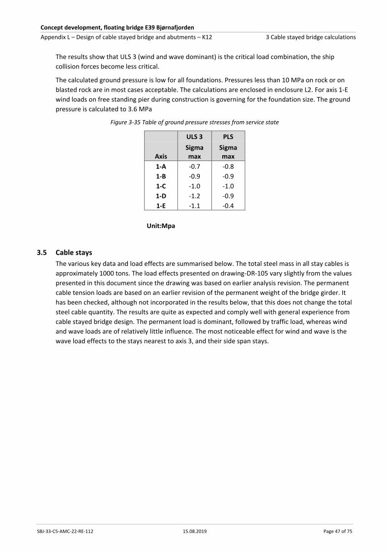
Concept development, floating bridge E39 Bjørnafjorden
Appendix L – Design of cable stayed bridge and abutments – K12 3 Cable stayed bridge calculations
SBJ-33-C5-AMC-22-RE-112 15.08.2019 Page 47 of 75
The results show that ULS 3 (wind and wave dominant) is the critical load combination, the ship
collision forces become less critical.
The calculated ground pressure is low for all foundations. Pressures less than 10 MPa on rock or on
blasted rock are in most cases acceptable. The calculations are enclosed in enclosure L2. For axis 1-E
wind loads on free standing pier during construction is governing for the foundation size. The ground
pressure is calculated to 3.6 MPa
Figure 3-35 Table of ground pressure stresses from service state
ULS 3 PLS
Axis Sigma max
Sigma max
1-A -0.7 -0.8
1-B -0.9 -0.9
1-C -1.0 -1.0
1-D -1.2 -0.9
1-E -1.1 -0.4
Unit:Mpa
3.5 Cable stays
The various key data and load effects are summarised below. The total steel mass in all stay cables is
approximately 1000 tons. The load effects presented on drawing-DR-105 vary slightly from the values
presented in this document since the drawing was based on earlier analysis revision. The permanent
cable tension loads are based on an earlier revision of the permanent weight of the bridge girder. It
has been checked, although not incorporated in the results below, that this does not change the total
steel cable quantity. The results are quite as expected and comply well with general experience from
cable stayed bridge design. The permanent load is dominant, followed by traffic load, whereas wind
and wave loads are of relatively little influence. The most noticeable effect for wind and wave is the
wave load effects to the stays nearest to axis 3, and their side span stays.
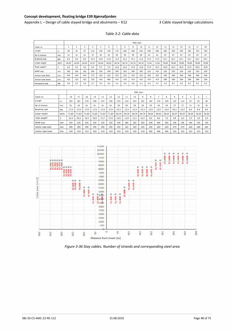
Concept development, floating bridge E39 Bjørnafjorden
Appendix L – Design of cable stayed bridge and abutments – K12 3 Cable stayed bridge calculations
SBJ-33-C5-AMC-22-RE-112 15.08.2019 Page 48 of 75
Table 3-2: Cable data
Figure 3-36 Stay cables. Number of strands and corresponding steel area

Concept development, floating bridge E39 Bjørnafjorden
Appendix L – Design of cable stayed bridge and abutments – K12 3 Cable stayed bridge calculations
SBJ-33-C5-AMC-22-RE-112 15.08.2019 Page 49 of 75
Figure 3-37 Stay cables. K12. Comparison environmental loads RP100yr
Figure 3-38 Stay cables. Max and min ULS forces and capacity

Concept development, floating bridge E39 Bjørnafjorden
Appendix L – Design of cable stayed bridge and abutments – K12 3 Cable stayed bridge calculations
SBJ-33-C5-AMC-22-RE-112 15.08.2019 Page 50 of 75
Figure 3-39 Stay cables. K12. Max ULS forces
Figure 3-40 Stay cables. K12. Min ULS forces

Concept development, floating bridge E39 Bjørnafjorden
Appendix L – Design of cable stayed bridge and abutments – K12 3 Cable stayed bridge calculations
SBJ-33-C5-AMC-22-RE-112 15.08.2019 Page 51 of 75
Figure 3-41 Stay cables. K12. Max characteristic load group forces
Figure 3-42 Stay cables. K12. Min characteristic load group forces
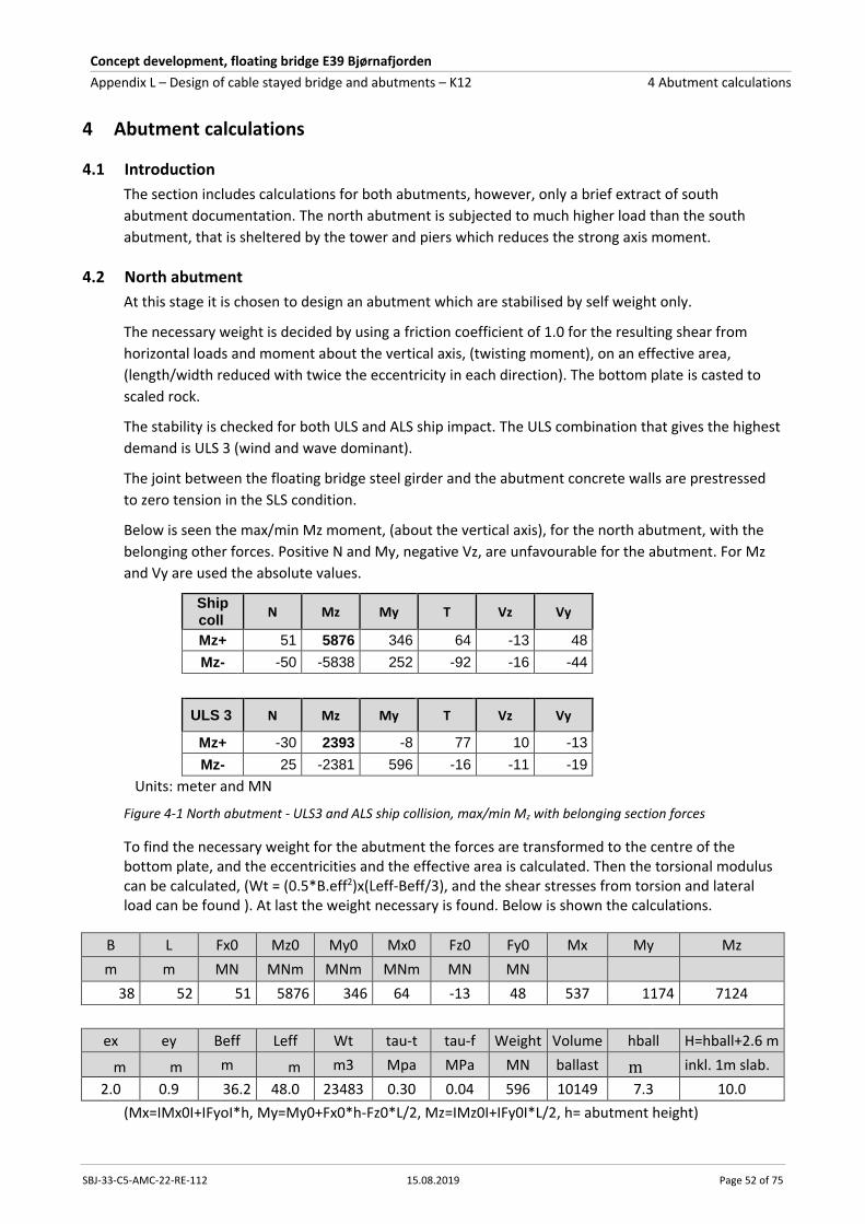
Concept development, floating bridge E39 Bjørnafjorden
Appendix L – Design of cable stayed bridge and abutments – K12 4 Abutment calculations
SBJ-33-C5-AMC-22-RE-112 15.08.2019 Page 52 of 75
4 Abutment calculations
4.1 Introduction
The section includes calculations for both abutments, however, only a brief extract of south
abutment documentation. The north abutment is subjected to much higher load than the south
abutment, that is sheltered by the tower and piers which reduces the strong axis moment.
4.2 North abutment
At this stage it is chosen to design an abutment which are stabilised by self weight only.
The necessary weight is decided by using a friction coefficient of 1.0 for the resulting shear from
horizontal loads and moment about the vertical axis, (twisting moment), on an effective area,
(length/width reduced with twice the eccentricity in each direction). The bottom plate is casted to
scaled rock.
The stability is checked for both ULS and ALS ship impact. The ULS combination that gives the highest
demand is ULS 3 (wind and wave dominant).
The joint between the floating bridge steel girder and the abutment concrete walls are prestressed
to zero tension in the SLS condition.
Below is seen the max/min Mz moment, (about the vertical axis), for the north abutment, with the
belonging other forces. Positive N and My, negative Vz, are unfavourable for the abutment. For Mz
and Vy are used the absolute values.
Ship coll
N Mz My T Vz Vy
Mz+ 51 5876 346 64 -13 48
Mz- -50 -5838 252 -92 -16 -44
ULS 3 N Mz My T Vz Vy
Mz+ -30 2393 -8 77 10 -13
Mz- 25 -2381 596 -16 -11 -19
Units: meter and MN
Figure 4-1 North abutment - ULS3 and ALS ship collision, max/min Mz with belonging section forces
To find the necessary weight for the abutment the forces are transformed to the centre of the bottom plate, and the eccentricities and the effective area is calculated. Then the torsional modulus can be calculated, (Wt = (0.5*B.eff2)x(Leff-Beff/3), and the shear stresses from torsion and lateral load can be found ). At last the weight necessary is found. Below is shown the calculations.
B L Fx0 Mz0 My0 Mx0 Fz0 Fy0 Mx My Mz
m m MN MNm MNm MNm MN MN
38 52 51 5876 346 64 -13 48 537 1174 7124
ex ey Beff Leff Wt tau-t tau-f Weight Volume hball H=hball+2.6 m
m m m m m3 Mpa MPa MN ballast m inkl. 1m slab.
2.0 0.9 36.2 48.0 23483 0.30 0.04 596 10149 7.3 10.0
(Mx=IMx0I+IFyoI*h, My=My0+Fx0*h-Fz0*L/2, Mz=IMz0I+IFy0I*L/2, h= abutment height)

Concept development, floating bridge E39 Bjørnafjorden
Appendix L – Design of cable stayed bridge and abutments – K12 4 Abutment calculations
SBJ-33-C5-AMC-22-RE-112 15.08.2019 Page 53 of 75
The extrapolation from the end node of the floating bridge to the centre of the abutment may be a
conservative assumption.
In above calculations iron ore with density 35 kN/m3 is used. Abutment concrete weight is 241 MN.
The Vessel Traffic Management System under consideration may reduce the risk for ship collision
and the ship impact forces. This in combination with a more no conservative approach for stability
calculations than used above, may bring down the abutment dimensions and weight requirement.
The SLS condition with no tension in the joint is governing for prestressing between the steel girder
and the abutment.
Tendons c/c 600 mm both in plates and bulkheads give space for about 170 tendons.
It is chosen to have 54 tendons 6-19 in the webs and 48 in the bottom slab. In top slab 48 tendons 6-
22 for partly counteracting the permanent My moment. (6-19 means 19 strands 0.6 in diameter)
Total compression from prestressing is 536 MN after losses.
Below is shown the steel stresses in the joint for the SLS combinations.
SLS N Mz My sig P sig N sig Mz sig My sum
N+ 39 -228 426 -141 10 8 70 -52
N- -34 183 -51 -141 -9 7 8 -135
Mz+ 4 1524 -80 -141 1 57 13 -70
Mz- 19 -1675 451 -141 5 62 74 0
My+ 8 -428 698 -141 2 16 114 -8
My- 3 572 -281 -141 1 21 46 -73
For ship collision the utilization for the most stressed tendon is 0.90, (1339 MPa*1.1/1640 MPa),
with additional strain from the load 0.14 %, (total strain 0.74 %).
The ALS capacity is determined by the concrete. At Mz=8100 MNm, (1.4 x collision load), the
concrete utilization is 1.0, and the tendon strain 1.1 %, (limit 2.4 %).
Figure 4-2 Joint floating bridge steel girder/concrete abutment
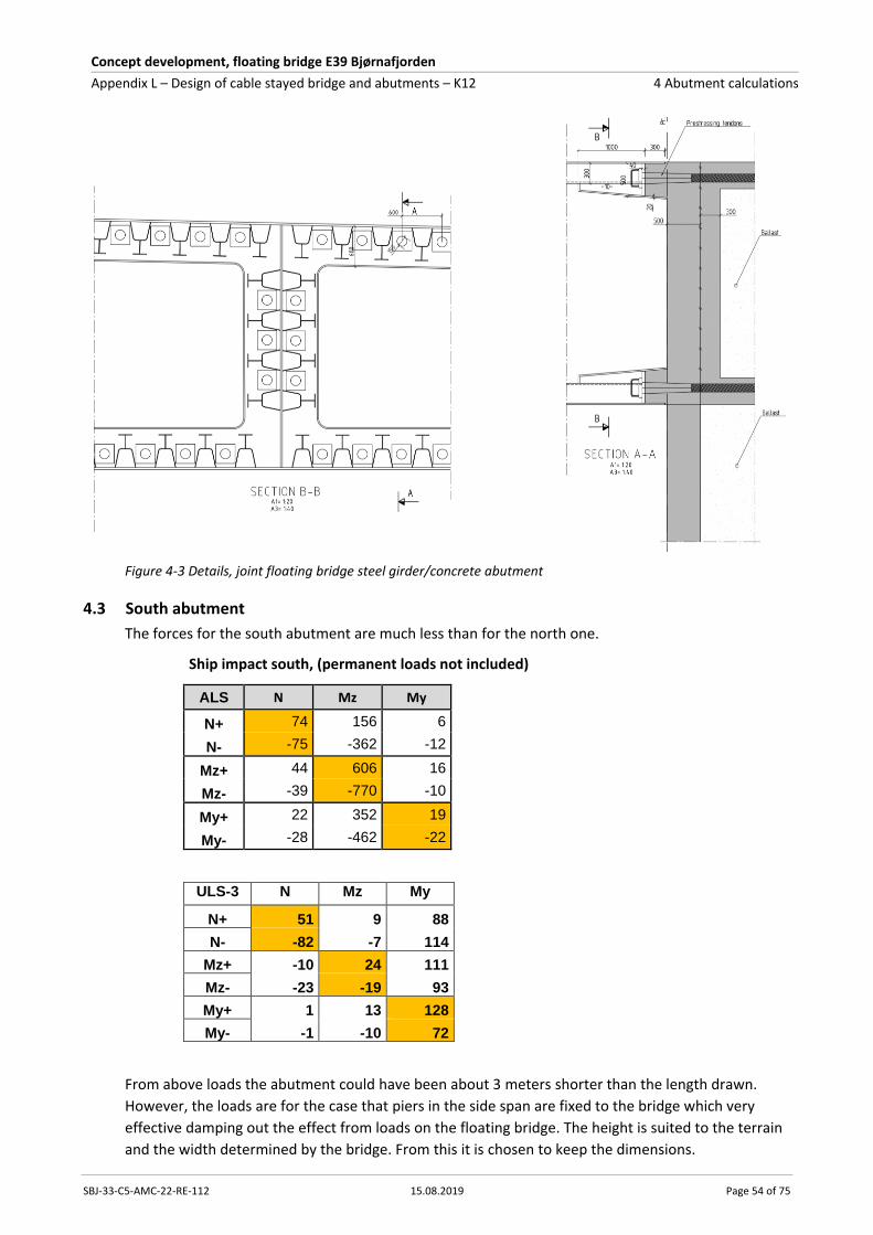
Concept development, floating bridge E39 Bjørnafjorden
Appendix L – Design of cable stayed bridge and abutments – K12 4 Abutment calculations
SBJ-33-C5-AMC-22-RE-112 15.08.2019 Page 54 of 75
Figure 4-3 Details, joint floating bridge steel girder/concrete abutment
4.3 South abutment
The forces for the south abutment are much less than for the north one.
Ship impact south, (permanent loads not included)
ALS N Mz My
N+ 74 156 6
N- -75 -362 -12
Mz+ 44 606 16
Mz- -39 -770 -10
My+ 22 352 19
My- -28 -462 -22
ULS-3 N Mz My
N+ 51 9 88
N- -82 -7 114
Mz+ -10 24 111
Mz- -23 -19 93
My+ 1 13 128
My- -1 -10 72
From above loads the abutment could have been about 3 meters shorter than the length drawn.
However, the loads are for the case that piers in the side span are fixed to the bridge which very
effective damping out the effect from loads on the floating bridge. The height is suited to the terrain
and the width determined by the bridge. From this it is chosen to keep the dimensions.

Concept development, floating bridge E39 Bjørnafjorden
Appendix L – Design of cable stayed bridge and abutments – K12 5 Wind analyses of construction stages
SBJ-33-C5-AMC-22-RE-112 15.08.2019 Page 55 of 75
5 Wind analyses of construction stages
Wind analyses of critical construction stages of the cable stayed bridge is performed with
NovaFrame.
The following four stages are considered critical and evaluated:
Figure 5-1 Stage A1. The last stage of casting the pier in axis 1E
The axis 1E pier with a total height of 56m casted. Climbing formwork at the top.
Figure 5-2 Stage A2: The last stage of casting the tower in axis 2
Tower fully casted up to elevation z=220m. Climbing formwork at the tower top. Crane and lift
mounted to the tower.
56
m
22
0m

Concept development, floating bridge E39 Bjørnafjorden
Appendix L – Design of cable stayed bridge and abutments – K12 5 Wind analyses of construction stages
SBJ-33-C5-AMC-22-RE-112 15.08.2019 Page 56 of 75
Figure 5-3 Stage B Cantilevered situation of cable stayed bridge before closing at the side span
Derrick cranes at the end of both 130m cantilevers. Crane and lift mounted to the tower is also
assumed, but this is not shown in the figure above.
Figure 5-4 Stage C. Cantilevered bridge girder in main span before closing in axis 3
Main span cantilever 370m. No special equipment included. Instead it is chosen to include 100 years
return period wind loads due to the assumption that this stage may last for a considerably longer
period of time compared to the other stages. 10 years return period is used in general for
construction stages.
Included impacts on these stages are:
Dead loads and pre-stressing of stay cables (included in a simplified manner)
Static wind loads
Dynamic buffeting wind loads
All wind directions are analysed with the P-Delta effect taken into account. Deformation loads and
secondary forces from previous construction stages are neglected. Imperfections are also neglected.
370m

Concept development, floating bridge E39 Bjørnafjorden
Appendix L – Design of cable stayed bridge and abutments – K12 5 Wind analyses of construction stages
SBJ-33-C5-AMC-22-RE-112 15.08.2019 Page 57 of 75
However, it is chosen to include an unbalance of permanent load by increasing the self weight of the
bridge girder in main span by 5 % for erected situations.
Effect of cracking is included by performing additional analyses with a reduced E-modulus, Ecracked =
0.4 x 30 000 MPa, for all tower elements in stages A2, B and C, and for all side span pier elements in
stage A1. Stability checks with cracked stiffness are performed for concept verification. However,
section capacity checks with cracked stiffness are considered a matter of detailed reinforcement
design. Additionally, it is seen that the cracked stiffness of 40 % will not have a significant impact on
the total forces due to the significant increased structural damping. Reference is made to the stability
checks. Thus, cracked stiffness is not considered for capacity checks in this phase.
Loads and load factors are in accordance with the Design basis.
Enclosure L3 describes the models and analyses in detail, and section forces, both ULS max/min and
characteristic forces, are presented. Capacity and stability checks due to forces resulting from this
Enclosure are included in Enclosure L1 and Enclosure L2 respectively.
A summary of the most important results is presented in the following.
Tower: Capacity checks of critical sections and foundation stability are performed. Constructions
stages are governing for the tower.
Stay cables: Constructions stages will not be governing for the cables as the maximum ULS force in
the longest cable in main span is ca. 8 MN.
Side span piers: Capacity checks of critical sections and foundation stability are performed.
Constructions stages are governing for the axis 1E pier.
Bridge girder (steel): Maximum bending moment about strong axis is 1700 MNm at axis 2 for stage C,
and maximum bending moment about weak axis is 55 MNm. Thus, construction stages are not
governing for the steel bridge girder.
Bridge girder (concrete): Capacity checks of critical sections are performed, but the construction
stages are not governing.
Table 5-1 Construction stage summary – values shown are not showing interdependent forces
Leg at bottom
Leg at crossbeam
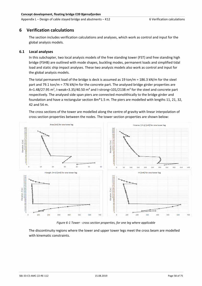
Concept development, floating bridge E39 Bjørnafjorden
Appendix L – Design of cable stayed bridge and abutments – K12 6 Verification calculations
SBJ-33-C5-AMC-22-RE-112 15.08.2019 Page 58 of 75
6 Verification calculations
The section includes verification calculations and analyses, which work as control and input for the
global analysis models.
6.1 Local analyses
In this subchapter, two local analysis models of the free standing tower (FST) and free standing high
bridge (FSHB) are outlined with mode shapes, buckling modes, permanent loads and simplified tidal
load and static ship impact analyses. These two analysis models also work as control and input for
the global analysis models.
The total permanent load of the bridge is deck is assumed as 19 ton/m = 186.3 kN/m for the steel
part and 79.1 ton/m = 776 kN/m for the concrete part. The analysed bridge girder properties are
A=1.48/27.95 m2, I-weak=3.35/40.50 m4 and I-strong=101/2138 m4 for the steel and concrete part
respectively. The analysed side span piers are connected monolithically to the bridge girder and
foundation and have a rectangular section 8m*1.5 m. The piers are modelled with lengths 11, 21, 32,
42 and 54 m.
The cross sections of the tower are modelled along the centre of gravity with linear interpolation of
cross section properties between the nodes. The tower section properties are shown below:
Figure 6-1 Tower - cross section properties, for one leg where applicable
The discontinuity regions where the lower and upper tower legs meet the cross beam are modelled
with kinematic constraints.
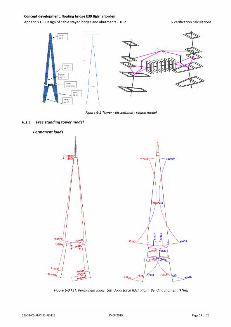
Concept development, floating bridge E39 Bjørnafjorden
Appendix L – Design of cable stayed bridge and abutments – K12 6 Verification calculations
SBJ-33-C5-AMC-22-RE-112 15.08.2019 Page 59 of 75
Figure 6-2 Tower - discontinuity region model
6.1.1 Free standing tower model
Permanent loads
Figure 6-3 FST. Permanent loads. Left: Axial force [kN]. Right: Bending moment [kNm]

Concept development, floating bridge E39 Bjørnafjorden
Appendix L – Design of cable stayed bridge and abutments – K12 6 Verification calculations
SBJ-33-C5-AMC-22-RE-112 15.08.2019 Page 60 of 75
Figure 6-4 FST. Permanent loads. Reactions [kN, kNm]
Mode shapes
Figure 6-5 FST. Mode shapes and natural frequencies
Buckling modes
Figure 6-6 FST. Buckling modes and critical factors (Ncr/NEd)

Concept development, floating bridge E39 Bjørnafjorden
Appendix L – Design of cable stayed bridge and abutments – K12 6 Verification calculations
SBJ-33-C5-AMC-22-RE-112 15.08.2019 Page 61 of 75
6.1.2 Free standing high bridge
In this model it is assumed that the stiffness and loads of all components are activated in one step.
Figure 6-7 FSHB. Local FE-model
Permanent loads
Figure 6-8 FSHB. Permanent loads. Axial forces and vertical bearing and reaction forces [kN]
Figure 6-9 FSHB. Permanent loads. Vertical displacement bridge girder [mm]
Figure 6-10 FSHB. Permanent loads. Weak axis bending moment [kNm]
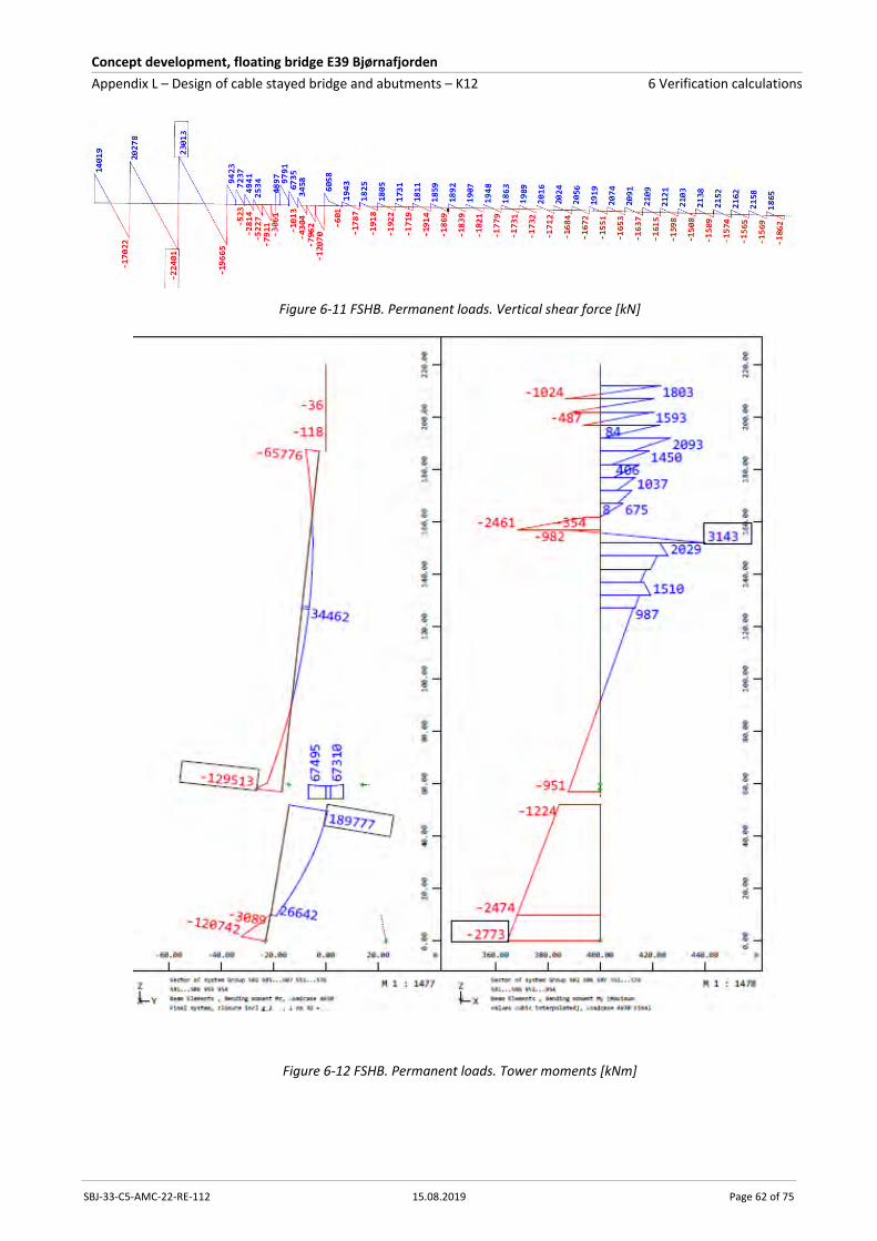
Concept development, floating bridge E39 Bjørnafjorden
Appendix L – Design of cable stayed bridge and abutments – K12 6 Verification calculations
SBJ-33-C5-AMC-22-RE-112 15.08.2019 Page 62 of 75
Figure 6-11 FSHB. Permanent loads. Vertical shear force [kN]
Figure 6-12 FSHB. Permanent loads. Tower moments [kNm]
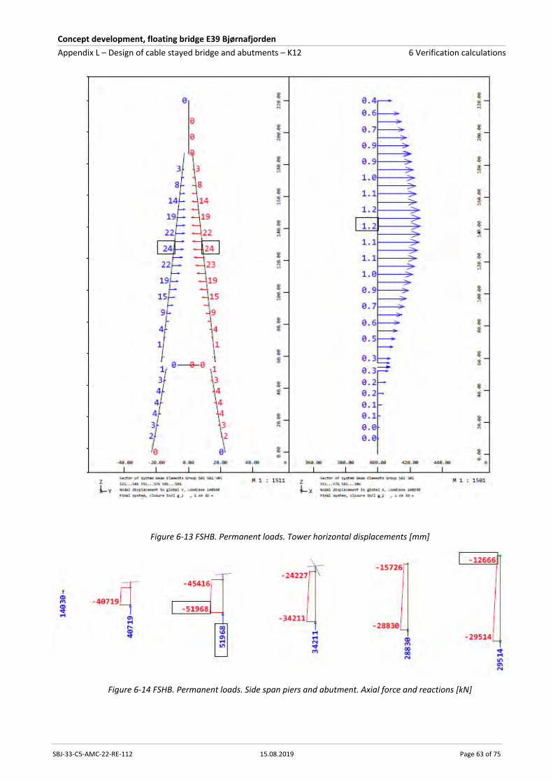
Concept development, floating bridge E39 Bjørnafjorden
Appendix L – Design of cable stayed bridge and abutments – K12 6 Verification calculations
SBJ-33-C5-AMC-22-RE-112 15.08.2019 Page 63 of 75
Figure 6-13 FSHB. Permanent loads. Tower horizontal displacements [mm]
Figure 6-14 FSHB. Permanent loads. Side span piers and abutment. Axial force and reactions [kN]

Concept development, floating bridge E39 Bjørnafjorden
Appendix L – Design of cable stayed bridge and abutments – K12 6 Verification calculations
SBJ-33-C5-AMC-22-RE-112 15.08.2019 Page 64 of 75
Figure 6-15 FSHB. Permanent loads. Side span piers and abutment. Bending moments [kNm]
Tide simulation
A unit load which gives 1 m vertical displacement at the tip of the main span cantilever is applied to
evaluate how tidal loads affect the high bridge.
The maximum stay cable force in the main span (outer cable, 18) is +-1300 kN
The maximum stay cable force in the side span (outer cable, 18) is +-531 kN
Figure 6-16 FSHB. Tide simulation. Vertical displacement [mm]
Figure 6-17 FSHB. Tide simulation. Longitudinal displacement [mm]
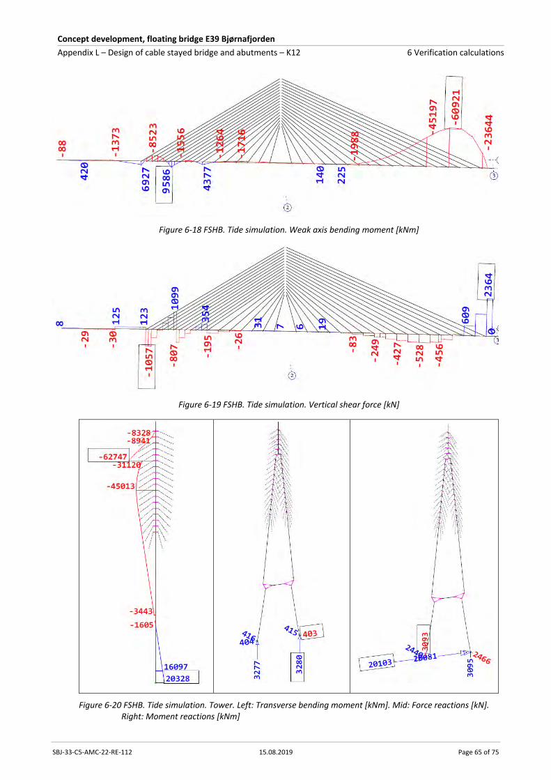
Concept development, floating bridge E39 Bjørnafjorden
Appendix L – Design of cable stayed bridge and abutments – K12 6 Verification calculations
SBJ-33-C5-AMC-22-RE-112 15.08.2019 Page 65 of 75
Figure 6-18 FSHB. Tide simulation. Weak axis bending moment [kNm]
Figure 6-19 FSHB. Tide simulation. Vertical shear force [kN]
Figure 6-20 FSHB. Tide simulation. Tower. Left: Transverse bending moment [kNm]. Mid: Force reactions [kN]. Right: Moment reactions [kNm]

Concept development, floating bridge E39 Bjørnafjorden
Appendix L – Design of cable stayed bridge and abutments – K12 6 Verification calculations
SBJ-33-C5-AMC-22-RE-112 15.08.2019 Page 66 of 75
Static ship impact simulation
A strong axis bending moment of 3000 MNm and a transverse force of 20 MN are applied at the tip
of the main span cantilever to evaluate how ship impact forces are distributed to the high bridge,
assuming static behaviour. This is a rough simplification and shall thus not be mistaken as design
forces. Nevertheless, it gives a good understanding of the stiffness distribution of the high bridge and
is used for sensitivity study for side span pier section types, concrete cracking and potential use of
bearings.
The results below are the result of non-linear analysis including permanent loads. The non-linear
effects are geometric non-linearity and the two transverse tower bearings only carrying compression.
There is no material non-linearity in the model. All stiffness is calculated using the nominal E-
modulus.
The maximum stay cable force increase/decrease with respect to the permanent load is +/-730 kN
(approximately the same in both side and front span).
Figure 6-21 FSHB. Ship impact simulation. Load application [kN, kNm]
Figure 6-22 FSHB. Ship impact simulation. Transverse displacement [mm]
Figure 6-23: FSHB. Ship impact simulation. Strong axis bending moment [kNm] Results not updated to reflect final global analyses which shows bending moment at tower of max 3300 MNm
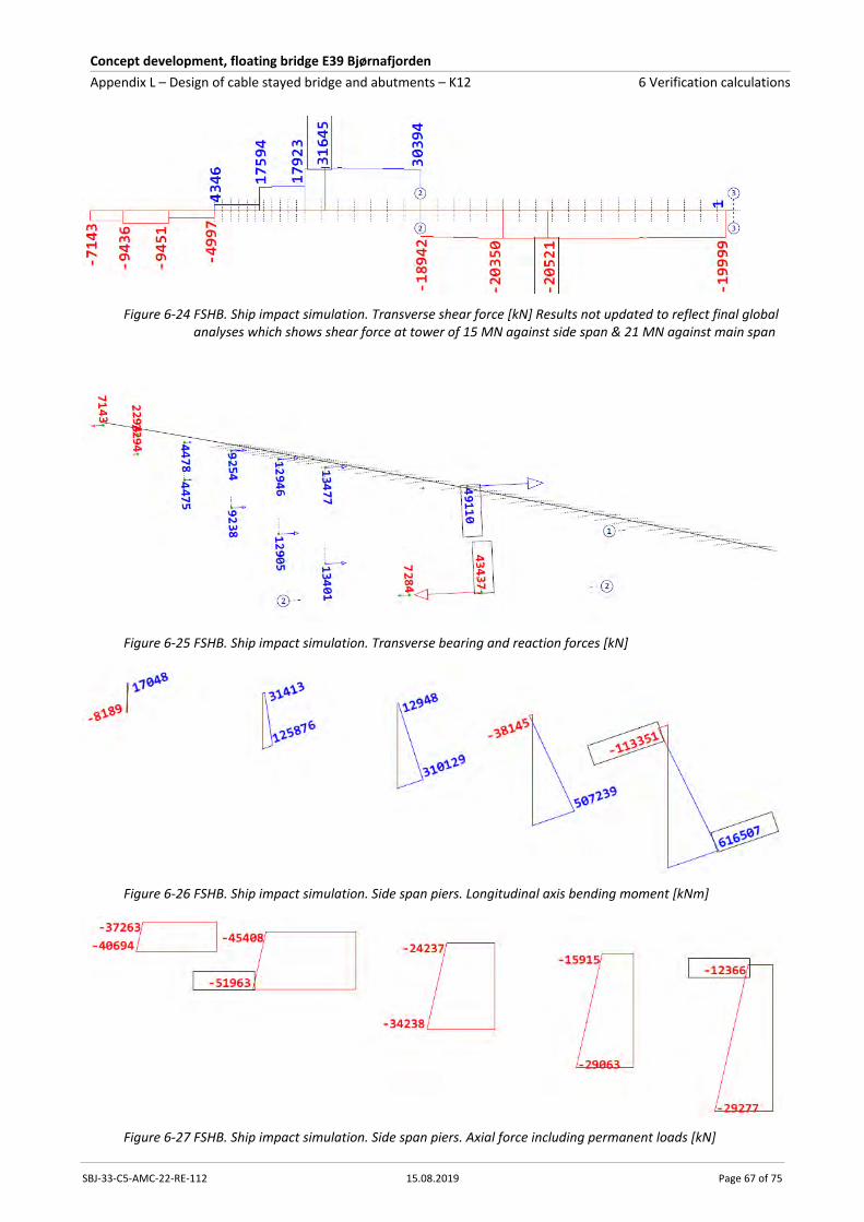
Concept development, floating bridge E39 Bjørnafjorden
Appendix L – Design of cable stayed bridge and abutments – K12 6 Verification calculations
SBJ-33-C5-AMC-22-RE-112 15.08.2019 Page 67 of 75
Figure 6-24 FSHB. Ship impact simulation. Transverse shear force [kN] Results not updated to reflect final global analyses which shows shear force at tower of 15 MN against side span & 21 MN against main span
Figure 6-25 FSHB. Ship impact simulation. Transverse bearing and reaction forces [kN]
Figure 6-26 FSHB. Ship impact simulation. Side span piers. Longitudinal axis bending moment [kNm]
Figure 6-27 FSHB. Ship impact simulation. Side span piers. Axial force including permanent loads [kN]
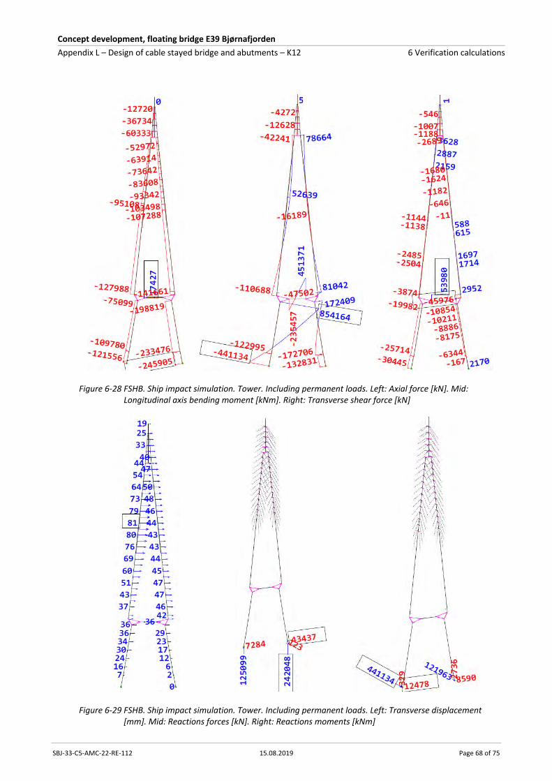
Concept development, floating bridge E39 Bjørnafjorden
Appendix L – Design of cable stayed bridge and abutments – K12 6 Verification calculations
SBJ-33-C5-AMC-22-RE-112 15.08.2019 Page 68 of 75
Figure 6-28 FSHB. Ship impact simulation. Tower. Including permanent loads. Left: Axial force [kN]. Mid: Longitudinal axis bending moment [kNm]. Right: Transverse shear force [kN]
Figure 6-29 FSHB. Ship impact simulation. Tower. Including permanent loads. Left: Transverse displacement [mm]. Mid: Reactions forces [kN]. Right: Reactions moments [kNm]

Concept development, floating bridge E39 Bjørnafjorden
Appendix L – Design of cable stayed bridge and abutments – K12 6 Verification calculations
SBJ-33-C5-AMC-22-RE-112 15.08.2019 Page 69 of 75
Mode shapes
Figure 6-30 FSHB. Mode shapes and natural frequencies
Buckling modes
Figure 6-31 FSHB. Buckling modes and critical factors (Ncr/NEd)
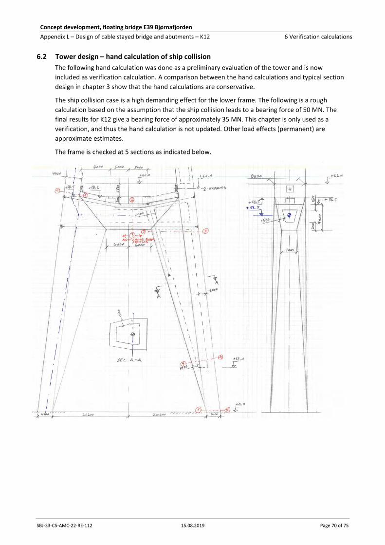
Concept development, floating bridge E39 Bjørnafjorden
Appendix L – Design of cable stayed bridge and abutments – K12 6 Verification calculations
SBJ-33-C5-AMC-22-RE-112 15.08.2019 Page 70 of 75
6.2 Tower design – hand calculation of ship collision
The following hand calculation was done as a preliminary evaluation of the tower and is now
included as verification calculation. A comparison between the hand calculations and typical section
design in chapter 3 show that the hand calculations are conservative.
The ship collision case is a high demanding effect for the lower frame. The following is a rough
calculation based on the assumption that the ship collision leads to a bearing force of 50 MN. The
final results for K12 give a bearing force of approximately 35 MN. This chapter is only used as a
verification, and thus the hand calculation is not updated. Other load effects (permanent) are
approximate estimates.
The frame is checked at 5 sections as indicated below.

Concept development, floating bridge E39 Bjørnafjorden
Appendix L – Design of cable stayed bridge and abutments – K12 6 Verification calculations
SBJ-33-C5-AMC-22-RE-112 15.08.2019 Page 71 of 75
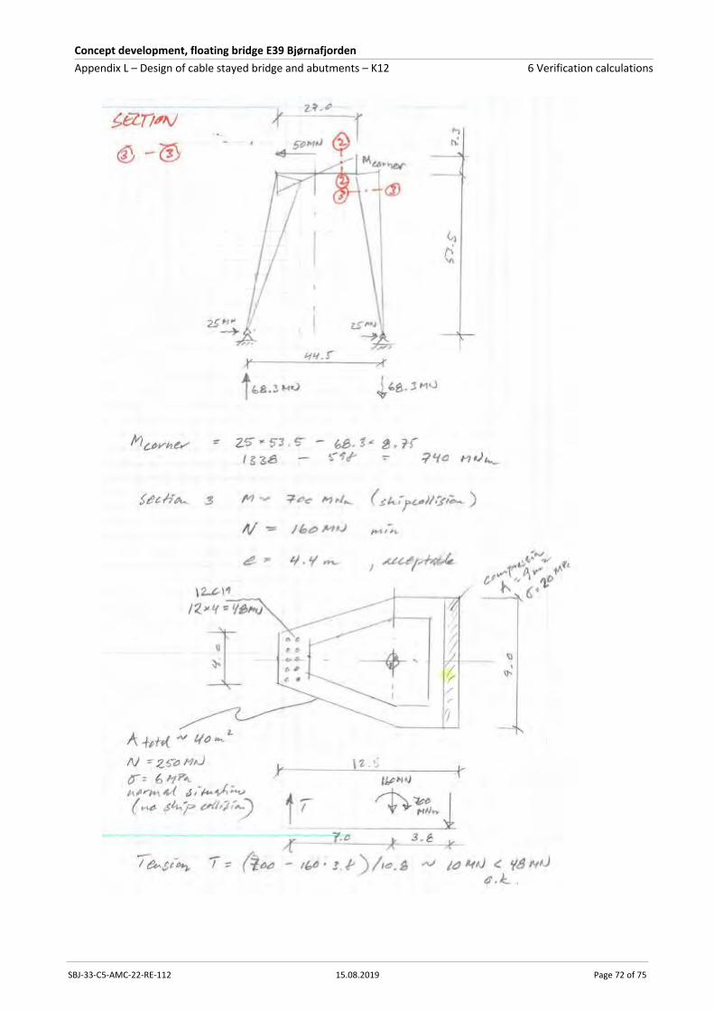
Concept development, floating bridge E39 Bjørnafjorden
Appendix L – Design of cable stayed bridge and abutments – K12 6 Verification calculations
SBJ-33-C5-AMC-22-RE-112 15.08.2019 Page 72 of 75
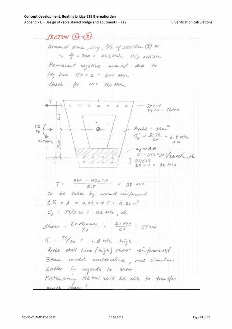
Concept development, floating bridge E39 Bjørnafjorden
Appendix L – Design of cable stayed bridge and abutments – K12 6 Verification calculations
SBJ-33-C5-AMC-22-RE-112 15.08.2019 Page 73 of 75

Concept development, floating bridge E39 Bjørnafjorden
Appendix L – Design of cable stayed bridge and abutments – K12 6 Verification calculations
SBJ-33-C5-AMC-22-RE-112 15.08.2019 Page 74 of 75

Concept development, floating bridge E39 Bjørnafjorden
Appendix L – Design of cable stayed bridge and abutments – K12 7 Enclosures
SBJ-33-C5-AMC-22-RE-112 15.08.2019 Page 75 of 75
7 Enclosures
Enclosure 1 Capacity diagrams
Enclosure 2 Foundation stresses
Enclosure 3 Analysis of construction stages