design of beam-columnslibvolume3.xyz/civil/btech/semester8/designanddrawingofsteel...68402 slide # 2...
TRANSCRIPT
68402 Slide # 1
Design of Beam-Columns
Monther Dwaikat Assistant Professor
Department of Building Engineering An-Najah National University
62323: Architectural Structures II
68402 Slide # 2
� Beam-Columns
� Moment Amplification Analysis
� Braced and Unbraced Frames
� Analysis/Design of Braced Frames
� Design of Base Plates
Beam-Column - Outline

68402 Slide # 3
Design for Flexure – LRFD Spec.
� Commonly Used Sections:
• I – shaped members (singly- and doubly-symmetric)
• Square and Rectangular or round HSS
68402 Slide # 4
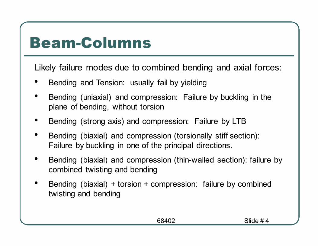
Beam-Columns
Likely failure modes due to combined bending and axial forces:
• Bending and Tension: usually fail by yielding
• Bending (uniaxial) and compression: Failure by buckling in the
plane of bending, without torsion
• Bending (strong axis) and compression: Failure by LTB
• Bending (biaxial) and compression (torsionally stiff section):
Failure by buckling in one of the principal directions.
• Bending (biaxial) and compression (thin-walled section): failure by
combined twisting and bending
• Bending (biaxial) + torsion + compression: failure by combined
twisting and bending

68402 Slide # 5
Beam-Columns � Structural elements subjected to combined flexural moments and axial
loads are called beam-columns
� The case of beam-columns usually appears in structural frames
� The code requires that the sum of the load effects be smaller than the
resistance of the elements
� Thus: a column beam interaction can be written as
� This means that a column subjected to axial load and moment will be
able to carry less axial load than if no moment would exist.
0.1≤
++
nyb
uy
nxb
ux
nc
u
M
M
M
M
P
P
φφφ
0.1≤∑n
ii
R
Q
φ
γ
68402 Slide # 6
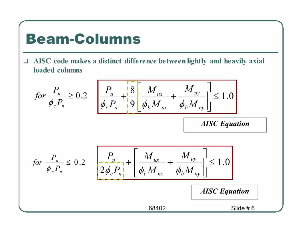
Beam-Columns
� AISC code makes a distinct difference between lightly and heavily axial
loaded columns
0.19
8≤
++
nyb
uy
nxb
ux
nc
u
M
M
M
M
P
P
φφφ
0.12
≤
++
nyb
uy
nxb
ux
nc
u
M
M
M
M
P
P
φφφ2.0≤
nc
u
P
Pfor
φ
2.0≥nc
u
P
Pfor
φ
AISC Equation
AISC Equation
68402 Slide # 7
Beam-Columns
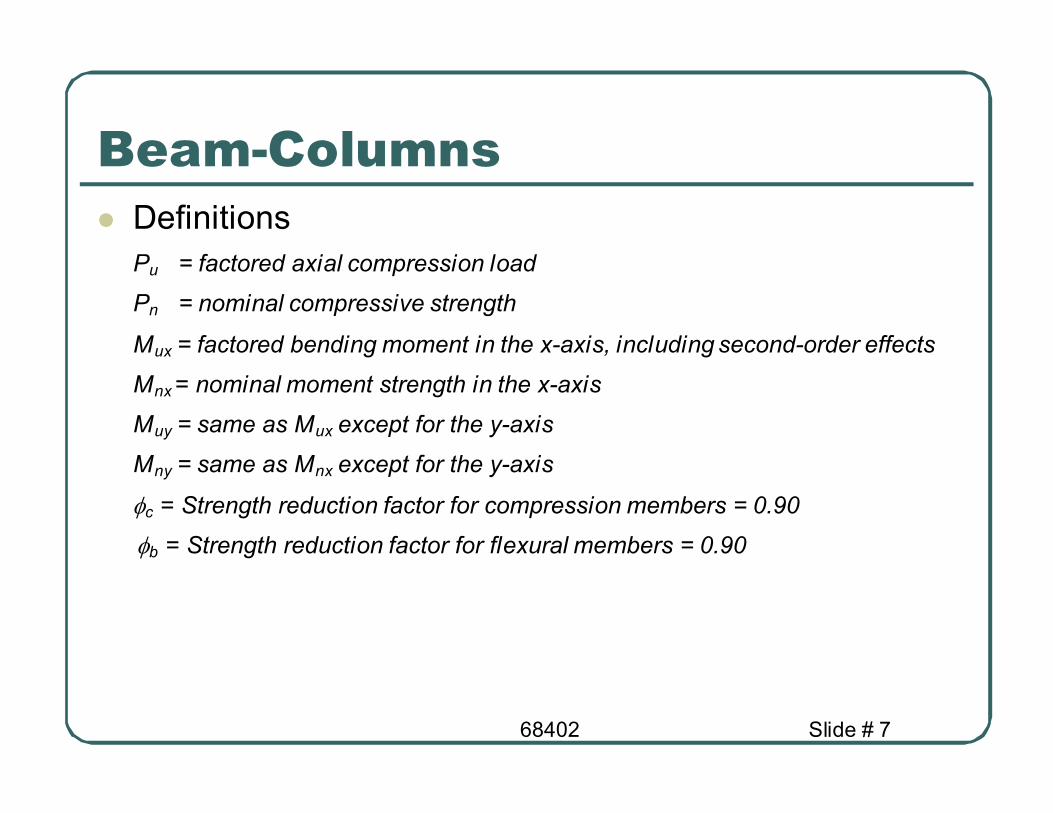
� Definitions
Pu = factored axial compression load
Pn = nominal compressive strength
Mux = factored bending moment in the x-axis, including second-order effects
Mnx = nominal moment strength in the x-axis
Muy = same as Mux except for the y-axis
Mny = same as Mnx except for the y-axis
φc = Strength reduction factor for compression members = 0.90
φb = Strength reduction factor for flexural members = 0.90

68402 Slide # 8
� The increase in slope for lightly axial-loaded columns represents the less
effect of axial load compared to the heavily axial-loaded columns
Pu/φφφφcPn
Safe Element
0.2
Mu/φφφφbMn
Beam-Columns
Unsafe Element
These are design charts that are a bit conservative than behaviour envelopes

68402 Slide # 9
Moment Amplification � When a large axial load exists, the axial load produces moments due to
any element deformation.
� The final moment “M” is the sum of the original moment and the
moment due to the axial load. The moment is therefore said to be
amplified.
� As the moment depends on the load and the original moment, the
problem is nonlinear and thus it is called second-order problem.
P
M
δδδδ
x
δδδδ P
68402 Slide # 10
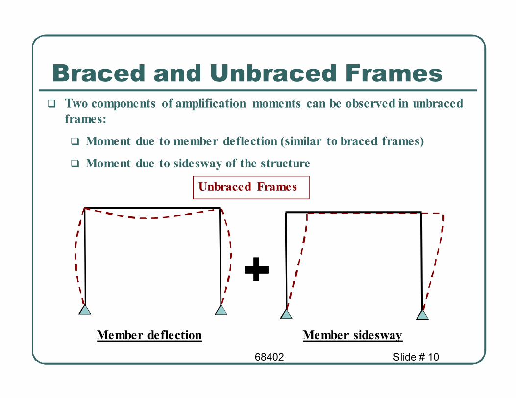
Braced and Unbraced Frames � Two components of amplification moments can be observed in unbraced
frames:
� Moment due to member deflection (similar to braced frames)
� Moment due to sidesway of the structure
Member deflection Member sidesway
Unbraced Frames
68402 Slide # 11
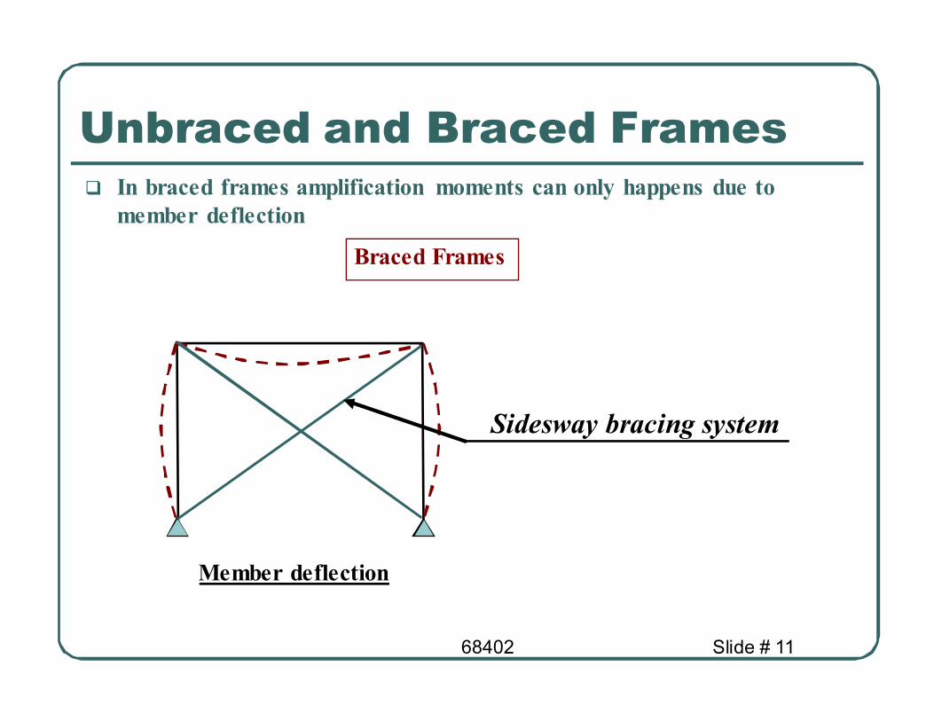
� In braced frames amplification moments can only happens due to
member deflection
Member deflection
Braced Frames
Sidesway bracing system
Unbraced and Braced Frames

68402 Slide # 12
� Braced frames are those frames prevented from sidesway.
� In this case the moment amplification equation can be simplified to:
ntxxux MBM 1=
1
1
1 ≥
−
=
e
u
m
P
P
CB AISC Equation
( )22
/ rKL
EAP
g
e
π=
� KL/r for the axis of bending considered
� K ≤ 1.0
ntyyuy MBM 1=
Unbraced and Braced Frames
68402 Slide # 13
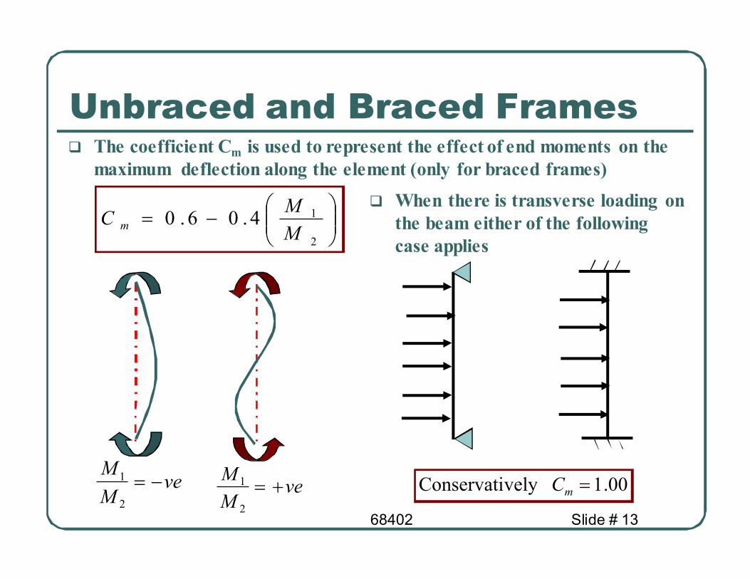
� The coefficient Cm is used to represent the effect of end moments on the
maximum deflection along the element (only for braced frames)
−=
2
14.06.0M
MC m
veM
M−=
2
1ve
M
M+=
2
1
� When there is transverse loading on
the beam either of the following
case applies
00.1vely Conservati =mC
Unbraced and Braced Frames
68402 Slide # 14
Ex. 5.1- Beam-Columns in Braced Frames
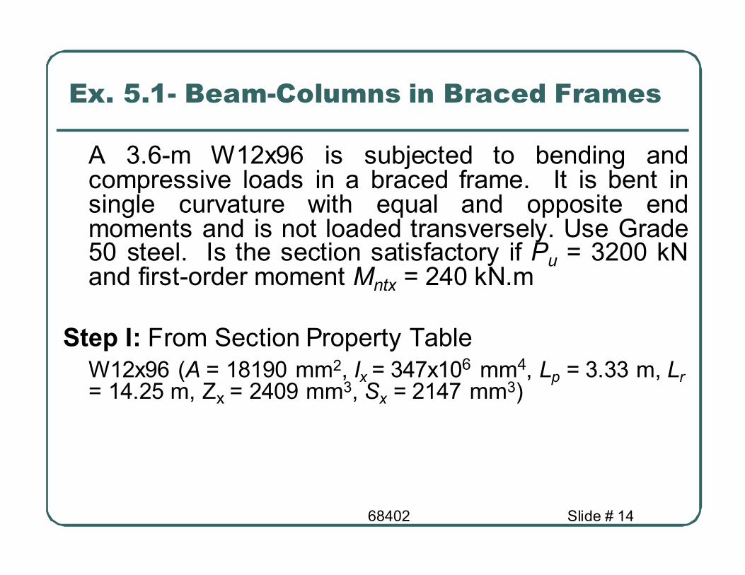
A 3.6-m W12x96 is subjected to bending and compressive loads in a braced frame. It is bent in single curvature with equal and opposite end moments and is not loaded transversely. Use Grade 50 steel. Is the section satisfactory if Pu = 3200 kN and first-order moment Mntx = 240 kN.m
Step I: From Section Property Table
W12x96 (A = 18190 mm2, Ix = 347x106 mm4, Lp = 3.33 m, Lr
= 14.25 m, Zx = 2409 mm3, Sx = 2147 mm
3)
68402 Slide # 15
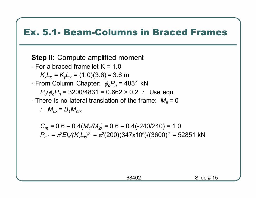
Step II: Compute amplified moment
- For a braced frame let K = 1.0
KxLx = KyLy = (1.0)(3.6) = 3.6 m
- From Column Chapter: φcPn = 4831 kN Pu/φcPn = 3200/4831 = 0.662 > 0.2 ∴ Use eqn.
- There is no lateral translation of the frame: Mlt = 0
∴ Mux = B1Mntx
Cm = 0.6 – 0.4(M1/M2) = 0.6 – 0.4(-240/240) = 1.0
Pe1 = π2EIx/(KxLx)2 = π2(200)(347x106)/(3600)2 = 52851 kN
Ex. 5.1- Beam-Columns in Braced Frames
68402 Slide # 16
Ex. 5.1- Beam-Columns in Braced Frames
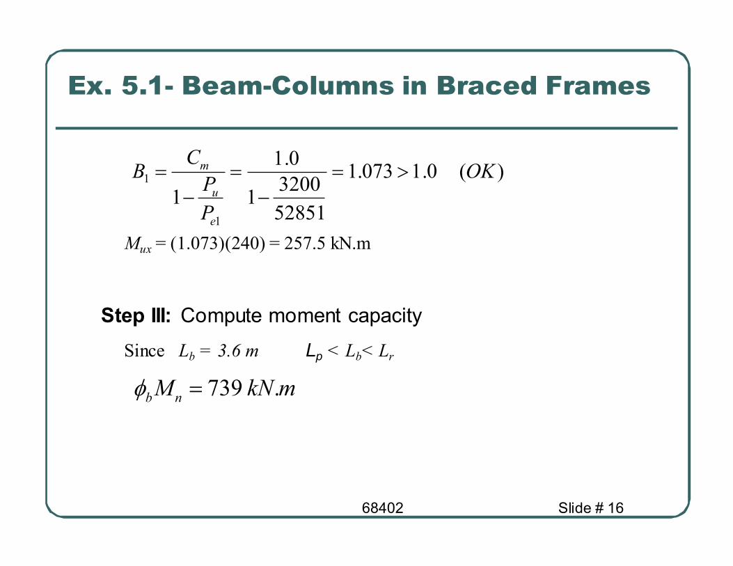
)(0.1073.1
52851
32001
0.1
11
1 OK
P
P
CB
e
u
m >=−
=−
=
Mux = (1.073)(240) = 257.5 kN.m
Step III: Compute moment capacity
Since Lb = 3.6 m Lp < Lb< Lr
mkNMnb
.739=φ
68402 Slide # 17
Ex. 5.1- Beam-Columns in Braced
Frames
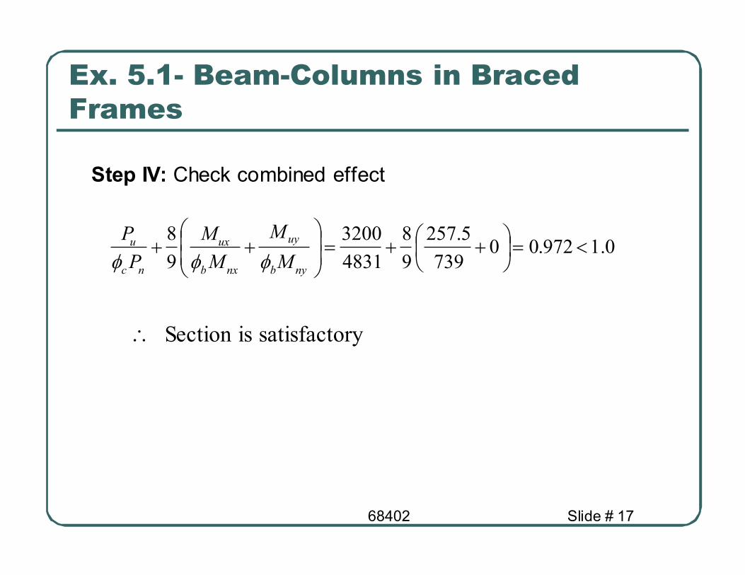
0.1972.00739
5.257
9
8
4831
3200
9
8<=
++=
++
nyb
uy
nxb
ux
nc
u
M
M
M
M
P
P
φφφ
∴ Section is satisfactory
Step IV: Check combined effect
68402 Slide # 18
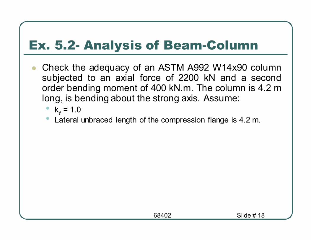
Ex. 5.2- Analysis of Beam-Column
� Check the adequacy of an ASTM A992 W14x90 column subjected to an axial force of 2200 kN and a second order bending moment of 400 kN.m. The column is 4.2 m long, is bending about the strong axis. Assume: • ky = 1.0
• Lateral unbraced length of the compression flange is 4.2 m.

68402 Slide # 19
Ex. 5.2- Analysis of Beam-Column
� Step I: Compute the capacities of the beam-column
φcPn = 4577 kN φMnx = 790 kN.m
φMny = 380 kN.m
� Step II: Check combined effect
2.0481.04577
2200>==
nc
u
P
P
φ
OK
0.1931.00790
400
9
8
4577
2200
9
8<=
++=
++
nyb
uy
nxb
ux
nc
u
M
M
M
M
P
P
φφφ

68402 Slide # 20
Design of Beam-Columns
� Trial-and-error procedure
• Select trial section • Check appropriate interaction formula.
• Repeat until section is satisfactory

68402 Slide # 21
Ex. 5.3 – Design-Beam Column
� Select a W shape of A992 steel
for the beam-column of the
following figure. This member is
part of a braced frame and is
subjected to the service-load axial force and bending moments
shown (the end shears are not
shown). Bending is about the
strong axis, and Kx = Ky = 1.0.
Lateral support is provided only at the ends. Assume that B1 = 1.0.
PD = 240 kN
PL = 650 kN
MD = 24.4 kN.m
ML = 66.4 kN.m
4.8 m
MD = 24.4 kN.m
ML = 66.4 kN.m

68402 Slide # 22
Ex. 5.3 – Design-Beam Column
� Step I: Compute the factored axial load and bending moments
Pu = 1.2PD + 1.6PL = 1.2(240)+ 1.6(650) = 1328 kN.
Mntx = 1.2MD + 1.6ML = 1.2(24.4)+ 1.6(66.4) = 135.5 kN.m.
B1 = 1.0 � Mux = B1Mntx = 1.0(135.5) = 135.5 kN.m
� Step II: compute φMnx, φPn • The effective length for compression and the unbraced length for
bending are the same = KL = Lb = 4.8 m.
• The bending is uniform over the unbraced length , so Cb=1.0
• Try a W10X60 with φPn = 2369 kN and φMnx = 344 kN.m
68402 Slide # 23
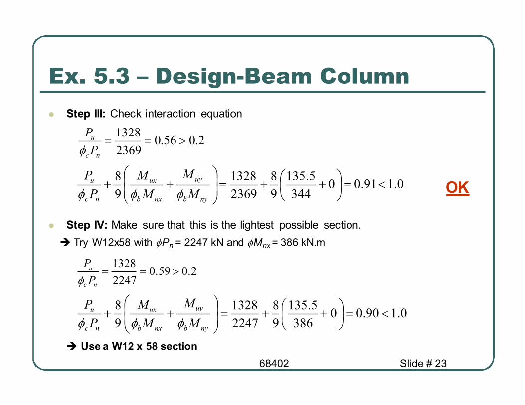
Ex. 5.3 – Design-Beam Column
� Step III: Check interaction equation
� Step IV: Make sure that this is the lightest possible section.
� Try W12x58 with φPn = 2247 kN and φMnx = 386 kN.m
� Use a W12 x 58 section
2.056.02369
1328>==
nc
u
P
P
φ
OK 0.191.00344
5.135
9
8
2369
1328
9
8<=
++=
++
nyb
uy
nxb
ux
nc
u
M
M
M
M
P
P
φφφ
0.190.00386
5.135
9
8
2247
1328
9
8<=
++=
++
nyb
uy
nxb
ux
nc
u
M
M
M
M
P
P
φφφ
2.059.02247
1328>==
nc
u
P
P
φ
68402 Slide # 24
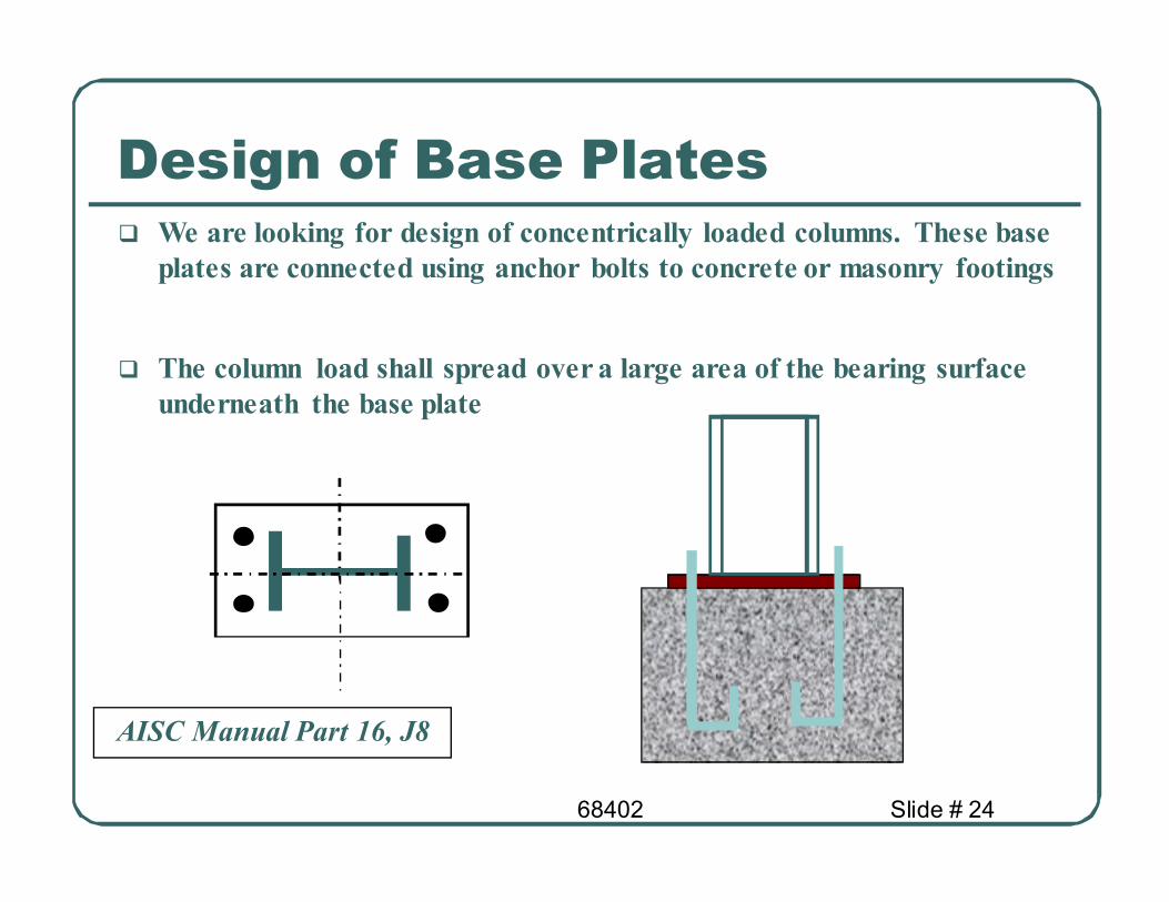
Design of Base Plates � We are looking for design of concentrically loaded columns. These base
plates are connected using anchor bolts to concrete or masonry footings
� The column load shall spread over a large area of the bearing surface
underneath the base plate
AISC Manual Part 16, J8

68402 Slide # 25
Design of Base Plates
up PP <φ
185.0 AfP cP′=
� The design approach presented here combines three design approaches
for light, heavy loaded, small and large concentrically loaded base plates
B 0.8 bf
0.95d
N
� The dimensions of the plate
are computed such that m and
n are approximately equal.
m
n Area of Plate is computed such that
where:
1
1
21
7.185.0 AfA
AAfP
ccP′≤′=
6.0=φIf plate covers the area of the footing
If plate covers part of the area of the footing
A1 = area of base plate
A2 = area of footing
f’c = compressive strength of concrete used
for footing

68402 Slide # 26
Design of Base Plates
2
95.0 dNm
−=
='
max
n
n
m
l
λ
2
8.0 fbBn
−=
pc
u
f
f
P
P
bd
dbX
φ
+=
2)(
4 X
X
dbn f
−−=
=
11
2
4
1'
λ
λλ
6.0=cφ
=pP Nominal bearing strength
y
u
y
upl
NFB
Pl5.1
FNB9.0
P2lt ≈=
Thickness of plate
However λ may be conservatively taken as 1
68402 Slide # 27
B
N
0.8bf
0.95d
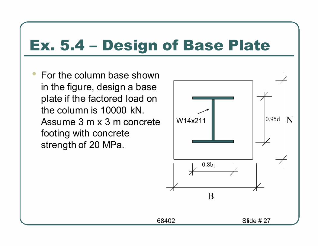
Ex. 5.4 – Design of Base Plate
• For the column base shown
in the figure, design a base
plate if the factored load on
the column is 10000 kN.
Assume 3 m x 3 m concrete footing with concrete
strength of 20 MPa.
W14x211
68402 Slide # 28
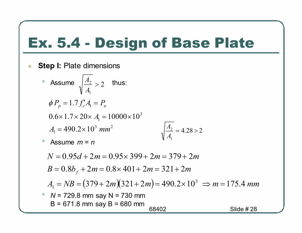
Ex. 5.4 - Design of Base Plate
� Step I: Plate dimensions
• Assume thus:
• Assume m = n
• N = 729.8 mm say N = 730 mm
B = 671.8 mm say B = 680 mm
21
2 >A
A
23
1
3
1
1
102.490
1010000207.16.0
7.1
mmA
A
PAfP ucp
×=
×=×××
=′=φ
( )( ) mmmmmNBA
mmmbB
mmmdN
f
4.175102.49023212379
232124018.028.0
2379239995.0295.0
3
1=⇒×=++==
+=+×=+=
+=+×=+=
228.41
2 >=A
A
68402 Slide # 29
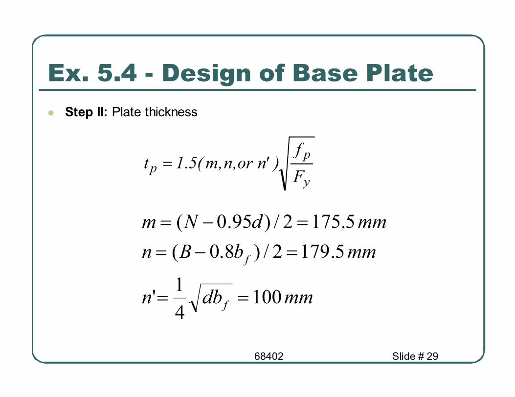
� Step II: Plate thickness
y
pp
F
f)'n or,n,m(5.1t =
mmdbn
mmbBn
mmdNm
f
f
1004
1'
5.1792/)8.0(
5.1752/)95.0(
==
=−=
=−=
Ex. 5.4 - Design of Base Plate
68402 Slide # 30
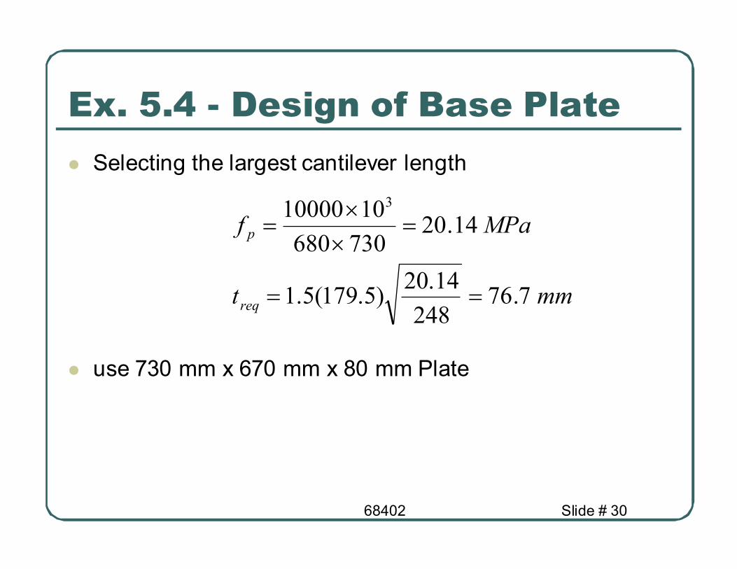
� Selecting the largest cantilever length
� use 730 mm x 670 mm x 80 mm Plate
mmt
MPaf
req
p
7.76248
14.20)5.179(5.1
14.20730680
1010000 3
==
=×
×=
Ex. 5.4 - Design of Base Plate