design of afa hotel 8 stories with steel …eprints.ums.ac.id/36184/1/1. publication.pdf · best...
TRANSCRIPT
DESIGN OF AFA HOTEL 8 STORIES WITH STEEL CONSTRUCTION
IN SURAKARTA
Publication
In partial fulfillment for the award of
Bachelor of Engineering Degree in Civil Engineering
Prepared by :
Dwi Prasetyo Utomo (D 100 112 011)
CIVIL ENGINEERING DEPARTMENT
ENGINEERING FACULTY
UNIVERSITAS MUHAMMADIYAH SURAKARTA
2015
DESIGN oF AFA HOTEL 8 STORIES WITH STEEL CONSTRUCTION
IN SURAKARTA
PERENCANAAN HOTEL AFA 8 LANTAI DENGAN KONSTRUKSI BAJA DI SURAKARTA
Dwi Prasetyo Utomo
Civil Engineering Department, Engineering Faculty
Universitas Muhammadiyah Surakarta, Jl. A. Yani Tromol Pos 1 Pabelan Kartasura Surakarta e-mail : [email protected]
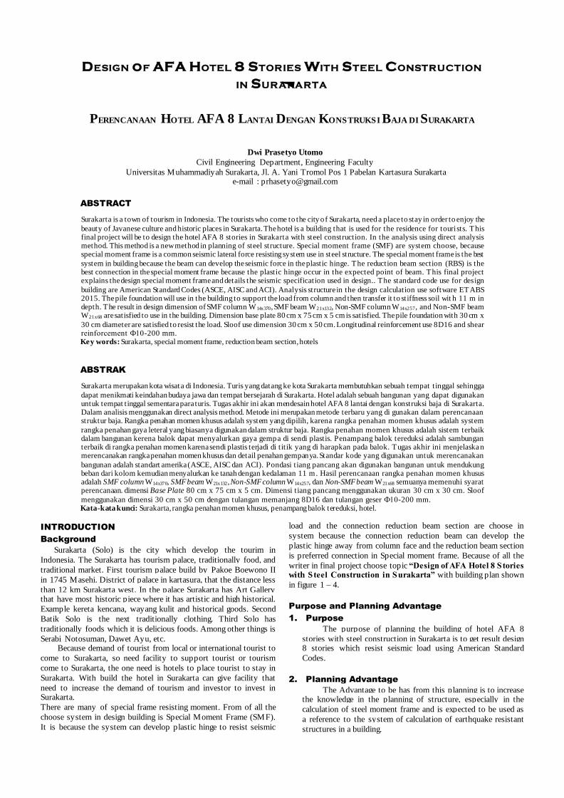
ABSTRACT
Surakarta is a town of tourism in Indonesia. The tourists who come to the city of Surakarta, need a place to stay in order to enjoy the
beauty of Javanese culture and historic places in Surakarta. The hotel is a building that is used for the residence for tourists. This final project will be to design the hotel AFA 8 stories in Surakarta with steel construction. In the analysis using direct analysis method. This method is a new method in planning of steel structure. Special moment frame (SMF) are system choose, because special moment frame is a common seismic lateral force resisting system use in steel structure. The special moment frame is the best
system in building because the beam can develop the seismic force in the plastic hinge. The reduction beam section (RBS) is the best connection in the special moment frame because the plastic hinge occur in the expected point of beam. This final project explains the design special moment frame and details the seismic specification used in design.. The standard code use for design
building are American Standard Codes (ASCE, AISC and ACI). Analysis structure in the design calculation use software ETABS 2015. The pile foundation will use in the building to support the load from column and then transfer it to stiffness soil wit h 11 m in depth. The result in design dimension of SMF column W 14x370, SMF beam W21x132, Non-SMF column W14x257, and Non-SMF beam W21x68 are satisfied to use in the building. Dimension base plate 80 cm x 75 cm x 5 cm is satisfied. The pile foundation with 30 cm x
30 cm diameter are satisfied to resist the load. Sloof use dimension 30 cm x 50 cm. Longitudinal reinforcement use 8D16 and shear reinforcement Ф10-200 mm.
Key words: Surakarta, special moment frame, reduction beam section, hotels
ABSTRAK
Surakarta merupakan kota wisata di Indonesia. Turis yang datang ke kota Surakarta membutuhkan sebuah tempat tinggal sehingga
dapat menikmati keindahan budaya jawa dan tempat bersejarah di Surakarta. Hotel adalah sebuah bangunan yang dapat digunakan untuk tempat tinggal sementara para turis. Tugas akhir ini akan mendesain hotel AFA 8 lantai dengan konstruksi baja di Surakarta. Dalam analisis menggunakan direct analysis method. Metode ini merupakan metode terbaru yang di gunakan dalam perencanaan struktur baja. Rangka penahan momen khusus adalah system yang dipilih, karena rangka penahan momen khusus adalah system
rangka penahan gaya leteral yang biasanya digunakan dalam struktur baja. Rangka penahan momen khusus adalah sistem terbaik dalam bangunan kerena balok dapat menyalurkan gaya gempa di sendi plastis. Penampang balok tereduksi adalah sambungan terbaik di rangka penahan momen karena sendi plastis terjadi di t it ik yang di harapkan pada balok. Tugas akhir ini menjelaska n merencanakan rangka penahan momen khusus dan detail penahan gempanya. Standar kode yang digunakan untuk merencanakan
bangunan adalah standart amerika (ASCE, AISC dan ACI). Pondasi tiang pancang akan digunakan bangunan untuk mendukung beban dari kolom kemudian menyalurkan ke tanah dengan kedalaman 11 m. Hasil perencanaan rangka penahan momen khusus adalah SMF column W14x370, SMF beam W21x132, Non-SMF column W14x257, dan Non-SMF beam W21x68 semuanya memenuhi syarat perencanaan. dimensi Base Plate 80 cm x 75 cm x 5 cm. Dimensi tiang pancang menggunakan ukuran 30 cm x 30 cm. Sloof
menggunakan dimensi 30 cm x 50 cm dengan tulangan memanjang 8D16 dan tulangan geser Ф10-200 mm. Kata-kata kunci: Surakarta, rangka penahan momen khusus, penampang balok tereduksi, hotel.
INTRODUCTION
Background
Surakarta (Solo) is the city which develop the tourim in
Indonesia. The Surakarta has tourism palace, traditionally food, and
traditional market. First tourism palace build by Pakoe Boewono II
in 1745 Masehi. District of palace in kartasura, that the distance less
than 12 km Surakarta west. In the palace Surakarta has Art Gallery that have most historic piece where it has artistic and high historical.
Example kereta kencana, wayang kulit and historical goods. Second
Batik Solo is the next traditionally clothing. Third Solo has
traditionally foods which it is delicious foods. Among other things is
Serabi Notosuman, Dawet Ayu, etc. Because demand of tourist from local or international tourist to
come to Surakarta, so need facility to support tourist or tourism
come to Surakarta, the one need is hotels to place tourist to stay in
Surakarta. With build the hotel in Surakarta can give facility that
need to increase the demand of tourism and investor to invest in Surakarta.
There are many of special frame resisting moment. From of all the
choose system in design building is Special Moment Frame (SMF).
It is because the system can develop plastic hinge to resist seismic
load and the connection reduction beam section are choose in
system because the connection reduction beam can develop the
plastic hinge away from column face and the reduction beam section
is preferred connection in Special moment frame. Because of all the
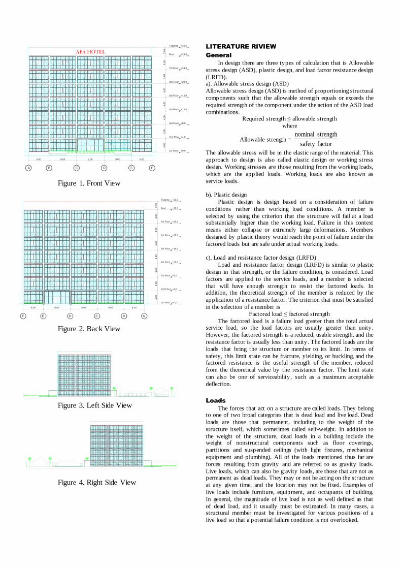
writer in final project choose topic “Design of AFA Hotel 8 Stories with S teel Construction in Surakarta” with building plan shown
in figure 1 – 4.
Purpose and Planning Advantage
1. Purpose
The purpose of planning the building of hotel AFA 8
stories with steel construction in Surakarta is to get result design 8 stories which resist seismic load using American Standard
Codes.
2. Planning Advantage
The Advantage to be has from this planning is to increase the knowledge in the planning of structure, especially in the
calculation of steel moment frame and is expected to be used as
a reference to the system of calculation of earthquake resistant
structures in a building.
AFA HOTEL
6,00 8,00 8,00 8,00 6,00
4,0
04,0
04,0
04,0
04,0
04,0
04,0
02,5
0
1st Floor
2nd Floor
3rd Floor
4th Floor
5th Floor
6th Floor
7th Floor
Roof
Topping +30,5
+28,0
+24,0
+20,0
+16,0
+12,0
+8,0
+4,0
+0,0
A B C D E F
1st Floor
2nd Floor
3rd Floor
4th Floor
5th Floor
6th Floor
7th Floor
Roof
Topping +30,5
+28,0
+24,0
+20,0
+16,0
+12,0
+8,0
+4,0
+0,0
6,008,008,008,006,00
4,0
04,0
04,0
04,0
04,0
04,0
04,0
02,5
0
ABCDEF
Figure 1. Front View
Figure 2. Back View
Figure 3. Left Side View
Figure 4. Right Side View
LITERATURE RIVIEW
General
In design there are three types of calculation that is Allowable
stress design (ASD), plastic design, and load factor resistance design
(LRFD). a). Allowable stress design (ASD)
Allowable stress design (ASD) is method of proportioning structural
components such that the allowable strength equals or exceeds the
required strength of the component under the action of the ASD load
combinations. Required strength ≤ allowable strength
where
Allowable strength = factorsafety
strength nominal
The allowable stress will be in the elastic range of the material. This
approach to design is also called elastic design or working stress
design. Working stresses are those resulting from the working loads,
which are the applied loads. Working loads are also known as
service loads.
b). Plastic design
Plastic design is design based on a consideration of failure
conditions rather than working load conditions. A member is
selected by using the criterion that the structure will fail at a load substantially higher than the working load. Failure in this context
means either collapse or extremely large deformations. Members
designed by plastic theory would reach the point of failure under the
factored loads but are safe under actual working loads.
c). Load and resistance factor design (LRFD)
Load and resistance factor design (LRFD) is similar to plastic
design in that strength, or the failure condition, is considered. Load
factors are applied to the service loads, and a member is selected
that will have enough strength to resist the factored loads. In addition, the theoretical strength of the member is reduced by the
application of a resistance factor. The criterion that must be satisfied
in the selection of a member is
Factored load ≤ factored strength
The factored load is a failure load greater than the total actual service load, so the load factors are usually greater than unity.
However, the factored strength is a reduced, usable strength, and the
resistance factor is usually less than unity. The factored loads are the
loads that bring the structure or member to its limit. In terms of
safety, this limit state can be fracture, yielding, or buckling, and the factored resistance is the useful strength of the member, reduced
from the theoretical value by the resistance factor. The limit state
can also be one of serviceability, such as a maximum acceptable
deflection.
Loads
The forces that act on a structure are called loads. They belong to one of two broad categories that is dead load and live load. Dead
loads are those that permanent, including to the weight of the
structure itself, which sometimes called self-weight. In addition to
the weight of the structure, dead loads in a building include the weight of nonstructural components such as floor coverings,
partitions and suspended ceilings (with light fixtures, mechanical
equipment and plumbing). All of the loads mentioned thus far are
forces resulting from gravity and are referred to as gravity loads.
Live loads, which can also be gravity loads, are those that are not as permanent as dead loads. They may or not be acting on the structure
at any given time, and the location may not be fixed. Examples of
live loads include furniture, equipment, and occupants of building.
In general, the magnitude of live load is not as well defined as that
of dead load, and it usually must be estimated. In many cases, a structural member must be investigated for various positions of a
live load so that a potential failure condition is not overlooked.

Studs Diameter 3/4"Welded wire fabric
"6x6 W1,4x1,4"
2" Lok-floor
Deck Composite Gage 22
Concrete 4,5" thick
F'c 3 ksi
Studs Diameter 3/4"
Beam
Beam
2 m
4,5"
5"2"
7"
12"
Earthquake loads are another special category and need to be
considered only in those geographic locations where it is a
reasonable probability of occurrence. A structural analysis of the effects of an earthquake requires an analysis of the structures
response to the ground motion produced by the earthquake. Simpler
methods are sometimes used in which the effect of the earthquake
are simulated by a system of horizontal loads, similar to those
resulting from wind pressure, acting at each floor level of building.
Flexure design
For flexure, the required and available strengths are moments.
For load and resistance factor design (LRFD) Equation can be
written as
nbu MM
Where :
M u= required moment strength by the controlling load combination.
M n= nominal moment strength of member. ϕb = resistance factor for bending (flexure).
Shear Design
For shear, the required and available strengths are shear. For
load and resistance factor design (LRFD) Equation can be written as
nvu VV
Where :
Vu = required shear strength by the controlling load combination. Vn = nominal shear strength of member.
Φv = resistance factor for shear.
Axial Design
For axial, the required and available strengths are compression.
For load and resistance factor design (LRFD) Equation can be written as
nau PP
Where : Pu = required axial strength by the controlling load combination.
Pn = nominal axial strength of member.
Φa = resistance factor for axial.
RESEARCH METHODS
Planning Data
Planning data use in this final project as follows: 1. The building is hotel 8 stories with steel construction and 1
basement in Surakarta.
2. The calculation for steel (deck composite, column, beam,
connection and stairs) and for concrete structure (driven pile
and pile cap). 3. This final project only calculation the main structure not
include sheet pile and slab on the ground.
4. High of column 1st – 8th story is 4 m.
5. Floor use deck composite with reinforced concrete.
6. Driven pile use in the design with use soil properties in site. 7. No review in terms of economic analysis, architectural, and
construction management.
8. Reviewing the implementation of the method is only related to
the calculation of structures only.
9. Standard use in the design in this final project is American Standard.
10. Structural Analysis for building use software ETABS 2015.
Tool Use for Planning
1. Software ETABS 2015
This software use for calculation in structural analysis the building.
2. Software AutoCAD v.2007
This software use for design the building will planning
and draw the building detail in the planning. 3. Software Microsoft Office 2013
This software use for make report, flow chart, data
analysis, , calculation and tables.
The Procedure of Planning
The procedure for planning the building follow as: 1. Step I : Data collection
At this step data are used for planning is the customized data
requirements are used.
2. Step II : Load analysis
At this step, after gathering data on continue with analysis of load and structure analysis using analysis software and then check
the requirement of standard codes.
3. Step III : Planning of building elements
At this step of the planning element analysis is carried out of
the building include beams, columns, base plate, connection, stairs. 4. Step IV : Planning the Foundation
At this step done analysis on foundation planning includes
analysis of pile reinforcement, bearing capacity of soil and force
which occurred in the Foundation.
5. Step V : Detailing of the structure At this step do the detailing of the structure based
calculation.
PLANNING RESULT
The results of planning the building of the hotel AFA 8 story with
steel construction in Surakarta as :
Floor
Planning a floor is use deck composite 2 "Lok-Floor with
reinforced welded wire fabric 6" x 6” W1,4x1,4 with thick concrete
is 4.5". Concrete compressive strength (f’c) 3 ksi and metal deck
yield stress (fy) 40 ksi.
Figure 5. Floor Deck Composite Detail
1. Stairs
Story high = 400 cm
Landing high = 200 cm Length of stairs = 320 cm
Length of Landing = 130 cm
Width of landing = 300 cm
Treads = 29 cm
Rise = 18 cm Yield stress fy = 36 ksi
α = 32,09o
Stairs beam = C8x18,75 in
Support beam = W12x35
4,80cm4,80cm
2,20cm
4,80cm
4,80cm
2,20cm
4,80cm4,80cm4,80cm
4,80cm
W14x257
W21x68
L 3x3x 516 in
Bolt Ø16 mmBolt Ø16 mm
L 3x3x 516 in
W21x68
W14x257
4,80cm4,80cm
2,20cm
4,80cm
4,80cm
2,20cm
4,80cm4,80cm4,80cm
4,80cm
W14x257
W21x68
L 3x3x 516 in
Bolt Ø16 mmBolt Ø16 mm
L 3x3x 516 in
W21x68
W14x257
CJPtop and bot.
CJPW21 web
Bolts as required
for erection
10 mm
single-plate
A572 Gr. 50
R = 25,865 cmW14x370
16,06cm 36,55cm
34,38 cm
7,5
6cm
16,06cm 36,55cm
34,38 cm
W 21x132
ASTM A992
W 14x370
ASTM A992
Backing Bar
CJP E70
PL 31,95x18,75x2,64 cm
A572 Gr.50
130 cm320 cm
300 c
m
135 c
m
AA
Ch
an
ne
l C8
x1
8,7
5 in
An
gle
L2
,5x2
,5x0
,19
in
Sta
irs B
eam
C8
x1
8,7
5 in
Ra
ise
d-P
atte
rn
Flo
or P
late
s
t =
316 in
Ra
ise
d-P
atte
rn
Flo
or P
late
s
t =
316 in
200
cm
130 cm320 cm150 cm
600 cm
Landing
18 c
m
29 cm
400
cm
Landing
Landing
2,2 cm
4,8
cm
4,8
cm
Bolt Ø16 mm
L 3x3x 516 in
2,2 cm
4,8
cm
4,8
cm
4,8 cm
0,39 cm
t = 0,794 cm
4,8 cm
2,82 cm
W14x38
W21x68
12,7 cm
35
,81
cm
5,08 cm
30
,73
cm
Bolt Ø16 mm
L 3x3x 516 in
W14x38
W21x68
4D16
2D16
Ø10-200
43
2 c
m
50
0 c
m
68
cm
300 cm
2D16
Figure 6. Stair Top View
Figure 7. Stair Detail Section A-A
Element of structure
Secure planning dimensions is used as the structure of the building
for secondary beam W14x38, Non-SMF beam W21x68, SMF beam
W21x132, Non-SMF column W14x257, SMF column W14x370.
Connection
Connection between secondary beam to Non-SMF beam:
Figure 8. Connection Detail Secondary Beam to Non-SMF Beam
SMF Reduction Beam Section Connection:
Figure 9. SMF Reduction Beam Section Connection
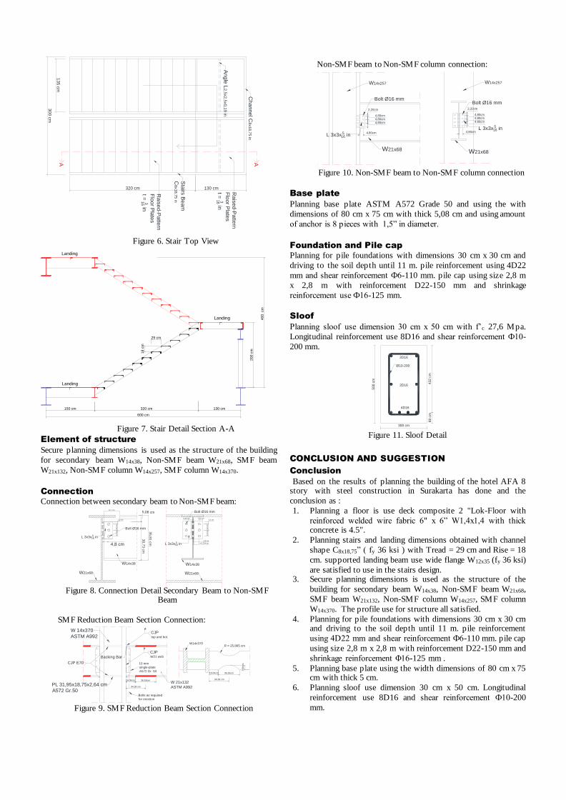
Non-SMF beam to Non-SMF column connection:
Figure 10. Non-SMF beam to Non-SMF column connection
Base plate
Planning base plate ASTM A572 Grade 50 and using the with
dimensions of 80 cm x 75 cm with thick 5,08 cm and using amount
of anchor is 8 pieces with 1,5” in diameter.
Foundation and Pile cap
Planning for pile foundations with dimensions 30 cm x 30 cm and
driving to the soil depth until 11 m. pile reinforcement using 4D22
mm and shear reinforcement Ф6-110 mm. pile cap using size 2,8 m
x 2,8 m with reinforcement D22-150 mm and shrinkage
reinforcement use Ф16-125 mm.
Sloof
Planning sloof use dimension 30 cm x 50 cm with f’c 27,6 Mpa.
Longitudinal reinforcement use 8D16 and shear reinforcement Ф10-
200 mm.
Figure 11. Sloof Detail
CONCLUSION AND SUGGESTION
Conclusion
Based on the results of planning the building of the hotel AFA 8 story with steel construction in Surakarta has done and the
conclusion as :
1. Planning a floor is use deck composite 2 "Lok-Floor with
reinforced welded wire fabric 6" x 6” W1,4x1,4 with thick concrete is 4.5".
2. Planning stairs and landing dimensions obtained with channel
shape C8x18,75” ( fy 36 ksi ) with Tread = 29 cm and Rise = 18
cm. supported landing beam use wide flange W12x35 (fy 36 ksi)
are satisfied to use in the stairs design. 3. Secure planning dimensions is used as the structure of the
building for secondary beam W14x38, Non-SMF beam W21x68,
SMF beam W21x132, Non-SMF column W14x257, SMF column
W14x370. The profile use for structure all satisfied.
4. Planning for pile foundations with dimensions 30 cm x 30 cm and driving to the soil depth until 11 m. pile reinforcement
using 4D22 mm and shear reinforcement Ф6-110 mm. pile cap
using size 2,8 m x 2,8 m with reinforcement D22-150 mm and
shrinkage reinforcement Φ16-125 mm .
5. Planning base plate using the width dimensions of 80 cm x 75 cm with thick 5 cm.
6. Planning sloof use dimension 30 cm x 50 cm. Longitudinal
reinforcement use 8D16 and shear reinforcement Ф10-200
mm.

Recomendation
Things to consider in planning high-rise building is:
1. Economical factor in the planning of the building is the very
important that needs to be considered, in order to get maximum results in planning a building.
2. The assumptions in the analysis of the structure must be
understood so that planning is in accordance with existing
conditions field.
3. Analysis of building structures that use software in the calculation must be within the thoroughness necessary input
data that affects the results in member force.
4. Each building has a different problem so expect for planners
to be able to understand the basic principles of calculation of
construction, analysis of the structure and Foundation.
REFFERENCE
American Institute of Steel Construction, 2011. Steel Construction
Manual, Fourteenth Edition. Chicago: AISC.
American Concrete Institute. 2011. Building Code Requirements for Structural Concrete and Commentary. ACI 318M -11.
Detroit: ACI.
American Society of Civil Engineering. 2010. Minimum Design
Loads for Buildings and Other Structures. SEI/ASCE 7-10.
Reston, VA: ASCE. Steel Deck Institute, 2006. Composite Steel Floor Deck, Standards
C1.0-2006. United States of America: Steel Deck Institute.
McCormac, Jack and Russell H. Brown. 2011. Design of Reinforced
Concrete. Ninth Edition. United States of America: John
Wiley & Sons Inc. Segui, William T. 2013. Steel Design. Fifth Edition. United States of
America: Cengage Learning.