design of acoustic partitions with thin plate-like...
TRANSCRIPT
PROCEEDINGS of the23rd International Congress on Acoustics
9 to 13 September 2019 in Aachen, Germany
Design of acoustic partitions with thin plate-like acoustic metamaterials
Felix LANGFELDT1; Wolfgang GLEINE2
Hamburg University of Applied Sciences, Germany
ABSTRACTAcoustic metamaterials have emerged as new means for sound control with extraordinary properties, suchas negative effective density and/or bulk modulus. Amongst the variety of different realizations of acousticmetamaterials, thin plate-like metamaterials (e.g. membrane-type acoustic metamaterials or inhomogeneousplates) have a high potential for improving the sound transmission loss of conventional partitions, espe-cially in the challenging low-frequency regime. These types of metamaterials have been previously shownto achieve very high sound transmission loss values which can exceed the corresponding mass-law valuesconsiderably. However, further investigations have shown that when these metamaterials are integrated intoa double wall partition, the beneficial effect of the metamaterials can be greatly diminished if an improperdesign is chosen. This contribution aims at providing a more detailed understanding of the important pa-rameters in the design of acoustic partitions with thin plate-like acoustic metamaterials. The metamaterial isrepresented by a simple black-box model in order to reduce the parameter space. Analytical calculations ofcombinations of the metamaterial with single and double walls are used to identify the most relevant designparameters and possible limitations in the acoustic performance. General design guidelines for acoustic par-titions are derived from these results and applied to laboratory test samples.
Keywords: acoustic metamaterial, glass wool, transmission loss, plate
1. INTRODUCTIONThe emergence of the so-called acoustic metamaterials 20 years ago has opened up new possibilities for
controlling the propagation of sound. The term acoustic metamaterials stands for composite structures com-posed of periodically arranged unit cells for the systematic manipulation of the effective parameters for soundwaves. Many different realizations of acoustic metamaterials exhibiting negative density or bulk modulus(and even both simultaneously) have been investigated thoroughly enabling new applications, such as acous-tic cloaks and perfect acoustic lenses (1). Amongst the many different kinds of acoustic metamaterials,the plate-like acoustic metamaterials (PAM) are of particular interest in applications of low-frequency noisecontrol. PAM are thin two-dimensional metamaterials exhibiting frequency bands at low frequencies withnegative density and—compared to the mass law—considerably enhanced sound transmission loss (STL).These properties make PAM promising candidates for applications in noise control engineering where massand installation space of noise reduction means are highly constrained (e.g. automotive or aeronautical engi-neering).
One of the first realizations of PAM, the so-called membrane-type acoustic metamaterials, were publishedby Yang et al. (2). They and subsequent publications demonstrated that these metamaterials, consisting ofsubwavelength sized unit cells with a thin prestressed membrane and small attached masses, can achievenarrowband anti-resonances with STL values much higher than the corresponding mass law. Similar to themembrane-type PAM are plates with periodically added masses, which have been investigated already inthe 1950s by Kurtze (3) and have been recently rediscovered in the context of acoustic metamaterials forenhanced low-frequency sound insulation (4, 5). Contrary to the membrane-type PAM, these metamaterialsdo not require a relatively stiff grid structure to subdivide the plate into individual unit cells and still exhibitlow-frequency anti-resonances with highly improved STL. Xiao et al. (6) investigated another type of PAM,where spring-mass resonators were distributed periodically on a plate and the STL of the plate could beconsiderably improved at the resonance frequencies of the attached resonators. Claeys et al. (7) appliedthis concept to an additively manufactured metamaterial enclosure with periodically embedded resonators toachieve a relatively broadband sound reduction below 1 kHz.1 Felix.Langfeldt@haw-hamburg2 [email protected]
4870
All these different PAM designs have been shown to exhibit large low-frequency STL values when thetransmission of sound is considered through the metamaterial only. However, in many applications it couldbe required to combine the metamaterials with conventional acoustic partitions, such as walls. One examplefor this is the aircraft sidewall, where the fuselage structure and the interior lining panels result in a doublewall-like arrangement. Previous studies of the performance of membrane-type acoustic metamaterials in theair gap of a double wall have shown that the anti-resonance effect of the metamaterial depends highly onthe position of the metamaterial within the double wall (8). In the worst case, the STL improvement of themetamaterial can be nullified by additional resonances appearing in the multi-layered structure. While inRef. (8) it was concluded that the optimal placement of the PAM inside the double wall was as close to onewall as possible, it remained inconclusive if this could be generalized to other double wall configurations aswell. In Ref. (9) it was shown that the STL of a double wall can be greatly improved at the mass-air-massresonance frequency by replacing one of the walls by a PAM with periodically attached resonators tunedto the mass-air-mass resonance frequency. However, in some applications it might be necessary to tune theanti-resonances of the PAM to other frequencies than the mass-air-mass resonance. In this case, it can beexpected that the performance of the PAM can be also significantly reduced if an improper design is chosen.
The objective of this contribution is to provide a more general understanding of the acoustical properties ofpartitions with additional PAM layers for the improvement of low-frequency sound insulation. In Section 2, ageneralized model for PAM using the effective surface mass density representation with a simple two degreesof freedom (2DOF) model is presented. This black-box model is able to represent a wide range of differentPAM designs using only a small set of parameters. It is employed in Section 3 to investigate the acousticinteractions of a PAM in combination with single and double walls. The paper is concluded in Section 4 witha summary of the findings and general recommendations for the design of acoustic partitions with PAM.
2. GENERALIZED MODEL FOR PLATE-LIKE ACOUSTIC METAMATERIALSThis section provides a generalized model to represent most PAM types with only a small set of easily
determinable parameters. First, Section 2.1 describes the effective mass representation used for the PAMmodeling. Then, the transfer matrix model used for modeling multi-layered partitions with PAM is describedbriefly. The models are validated in Section 2.3 using simulations and experiments.
2.1 Effective mass representationSince, typically, the PAM are very thin compared to the acoustic wavelength, they can be represented as a
slab with a frequency-dependent effective surface mass density m′′eff. For the purpose of this contribution, the
PAM considered here are characterized by a single anti-resonance (with greatly increased effective surfacemass density) followed by a resonance (with near-zero m′′eff
). Thus, the following 2DOF representation form′′eff
can be used:
m′′eff(ω) = m′′0|p|2(z − iω)(z∗ − iω)
|z|2(p − iω)(p∗ − iω), (1)
where m′′0 is the static surface mass density of the PAM and z and p are the complex zero and pole of thePAM, respectively. These are given by
z = i2π fR(√
1 − ζ2R + iζR
)and p = i2π fP
(√1 − ζ2
P + iζP
), (2)
with the resonance frequency fR, anti-resonance frequency fP, and the corresponding modal damping ratiosζR and ζP. In the undamped case, ζR = ζP = 0 and Eq. (1) reduces to
m′′eff( f ) = m′′01 − f 2/ f 2
R
1 − f 2/ f 2P
. (3)
Similar formulations to Eqs. (1) and (3) have been used previously to characterize the effective materialproperties of PAM (e.g. (6, 9)). The advantage of these models is that every PAM design can be representedby Eq. (1) with only five parameters which are relatively easy to determine using experimental, numerical, oranalytical methods. In the undamped case of Eq. (3) it is even sufficient to determine only three parameters(the PAM mass and the two characteristic frequencies) to fully describe the dynamic behavior of the PAM atlow frequencies. On the other hand, Eq. (1) can also be interpreted as a black-box model which enables thedesign of acoustic partitions with PAM using quantities like mass, (anti-)resonance frequencies, and dampingbefore any specific PAM designs are chosen. Once eligible values for these parameters have been determined,the PAM can be designed specifically for achieving these design parameters.
4871
2.2 Transfer matrix modelIn order to estimate the STL of multi-layered acoustic partitions with PAM, the transfer matrix method is
employed. A 2-by-2 transfer matrix T relates the acoustic pressure and particle velocity on both sides of alaterally infinite layer (e.g. an air gap or a wall) and can be easily calculated for multi-layered partitions bymultiplying the transfer matrices of all layers (10). The four elements T11, T12, T21, and T22 of a transfermatrix can be used to calculate the characteristic acoustic quantities of the partition, such as the sound trans-mission loss TL. For common layers, such as air layers and porous absorber blankets, analytical expressionsfor the transfer matrices can be found in the literature (e.g. (10, pp. 244–257)). In the case of an acousticallythin slab, the transfer matrix can be expressed in terms of the wall impedance Zw as
Tw =
[1 Zw(ω)0 1
]. (4)
For a limp wall with surface mass density m′′, the wall impedance is given by Zw(ω) = iωm′′. For themodeling of a PAM layer, the wall impedance is obtained in the same form but with m′′ replaced by theeffective surface mass density given in Eq. (1), i.e. Zw(ω) = iωm′′eff
(ω) (8).
2.3 ValidationThe modeling approach for acoustic partitions with PAM presented in this section is first validated using
finite element model (FEM) simulations for two different types of PAM designs. Then, experimental resultsfor a plate model with a PAM layer under diffuse field excitation are presented to validate the transfer matrixmodel.
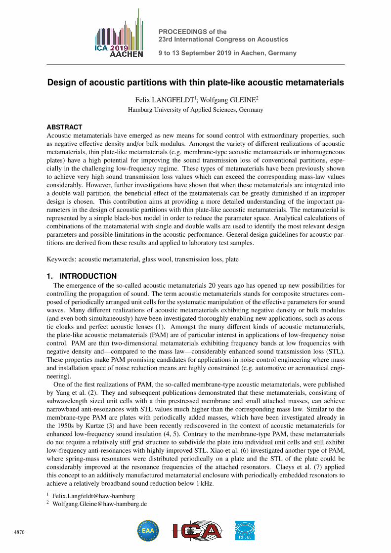
Figure 1(a) shows the simulated normal incidence sound transmission loss TL of a periodic PAM unit cellconsisting of a thin film with an attached ring mass (similar to the PAM investigated in Ref. (5)). The edgeboundary conditions of the unit cell were periodic in order to simulate a laterally unbounded metamaterialplate. The film material was a 100 µm thick PET film (density ρ = 1570 kg/m3, Young’s modulus E =
4.7 GPa, Poisson’s ratio ν = 0.4, and structural loss factor η = 10 %) and the dimensions of the unit cellwere given by 35 mm × 35 mm. The polyamide ring mass was tM = 1.6 mm thick with an outer and innerdiameter of dM,o = 18 mm and dM,i = 6.4 mm, respectively, resulting in an added mass of M = 0.39 g.Thus, the static surface mass density of this PAM is comparatively low with m′′0 = 0.48 kg/m2. For theanalytical modelling using the 2DOF model in Eq. (1), the characteristic frequencies fP and fR as well as thecorresponding damping ratios are provided in Table 1. It should be noted that, for simplicity, the dampingratios have been determined by ζP = ζR = 2η.
The analytical and numerical results in Fig. 1(a) exhibit an excellent agreement up to the resonance fre-quency of the metamaterial fR = 320 Hz. At higher frequencies, the numerical results indicate a second-orderanti-resonance at around 700 Hz which the 2DOF model cannot reproduce because Eq. (1) only includes oneanti-resonance of the PAM. However, Eq. (1) can in principle be readily extended to include higher-orderpoles and zeros. Nevertheless, for the analysis of multi-layered partitions with PAM in Section 3 as well as inmany practical applications of PAM it suffices to consider only the first anti-resonance of the metamaterial.
Figure 1(b) shows the numerical and analytical STL results of a considerably different PAM design consist-
0
2
4
6
8
10
12
14
16
200 500100 1000
(a)
TL
indB
f in Hz0
5
10
15
20
25
30
35
40
200 400 20001000
(b)
TL
indB
f in Hz
2DOF modelFEM
Mass law
Figure 1 – Numerical and analytical results using the 2DOF model for the normal incidence sound trans-mission loss TL of two different PAM designs. (a) Thin film with added masses; (b) Plate withmicro-resonators (unit cell design from Ref. (9)).
4872
Table 1 – 2DOF model parameters of the different investigated PAM configurations
Configuration m′′0 fP ζP fR ζR
Film with ring masses (Fig. 1(a)) 0.48 235 20 320 20Plate with micro-resonators (Fig. 1(b)) 4.61 539 10 620 10
PAM for plate model (Fig. 2(b)) 0.43 390 60 585 60
kg/m2 Hz % Hz %
ing of a plate with attached micro resonators. The geometrical and material specifications of this metamaterialare given in Ref. (9). The resulting parameters for the 2DOF model are provided in Table 1. It can be seenthat this metamaterial is nearly ten times heavier than the one shown in Fig. 1(a). Therefore, the TL valuesof this PAM are considerably higher. The agreement between the analytical and numerical results is againexcellent. Since for this PAM no higher-order anti-resonance is present within the frequency range of interest,the good agreement extends over all frequencies shown in Fig. 1(b).
It therefore can be concluded that the proposed 2DOF model is capable of representing many differentPAM designs using only five parameters for frequencies up to the second- and higher-order (anti-)resonancesof the metamaterial unit cell.
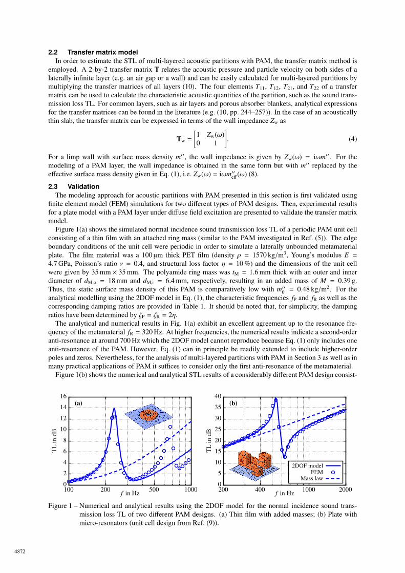
An experimental validation of the transfer matrix model for multi-layered partitions with PAM was con-ducted in the acoustic laboratory of the Hamburg University of Applied Sciences using a 50 cm × 50 cm platemodel. The diffuse field sound transmission loss TLdiff was measured according to ISO 15186-1 by mountingthe sample inside a transmission window in between a reverberation chamber and a hemi-anechoic room (seeFig. 2(a)) and measuring the transmitted sound power with a sound intensity probe. As shown in Fig. 2(c),the sample consists of a baseplate which is composed of a 3 mm thick MDF plate with a 25 mm layer oflightweight glass wool on top. The surface mass density of this baseplate was measured at m′′ = 2.85 kg/m2.A PAM made up of a PET film with 169 polyamide ring masses is attached to the transmission window frameusing tape (see Fig. 2(b)) with a distance of 50 mm measured from the MDF plate. The surface mass densityof the PAM was given by m′′0 = 0.43 kg/m2 which is only 15 % of the baseplate mass.
In the analytical model using the transfer matrix method, the MDF plate was modelled as a limp wall withits surface mass density of 2.7 kg/m2. The glass wool layer was represented by an equivalent fluid model(11) with a limp frame approximation (10, pp. 252-253) using the material parameters density ρ = 6 kg/m3,porosity φ = 0.99, and static flow resistivity σ = 19 kNs/m4. For the PAM layer, the 2DOF model with theparameters provided in Table 1 was used. The diffuse field sound transmission loss of the finite sized testsample was calculated with the resulting transfer matrices using the spatial windowing method by Bonfiglioet al. (12).
MDF plate (2.7 kg/m2)
PAM
50 mm
(c)
(a) (b)
(t = 25 mm,ρ = 6 kg/m3,
φ = 0.99,σ = 19 kNs/m4)
Glass wool
0
5
10
15
20
25
30
35
40
45
200 400 20001000
(d)
TL
diff
indB
f in Hz
BaseplateBaseplate + PAM
Figure 2 – Experimental and analytical results for the multi-layered partition consisting of a plate, glass wool,and PAM. (a) MDF plate with glass wool inside the transmission window frame; (b) Metamaterialfilm with ring masses; (c) Schematical drawing of the layering structure; (d) Measured (symbols)and analytically calculated (lines) diffuse field sound transmission loss TLdiff .
4873
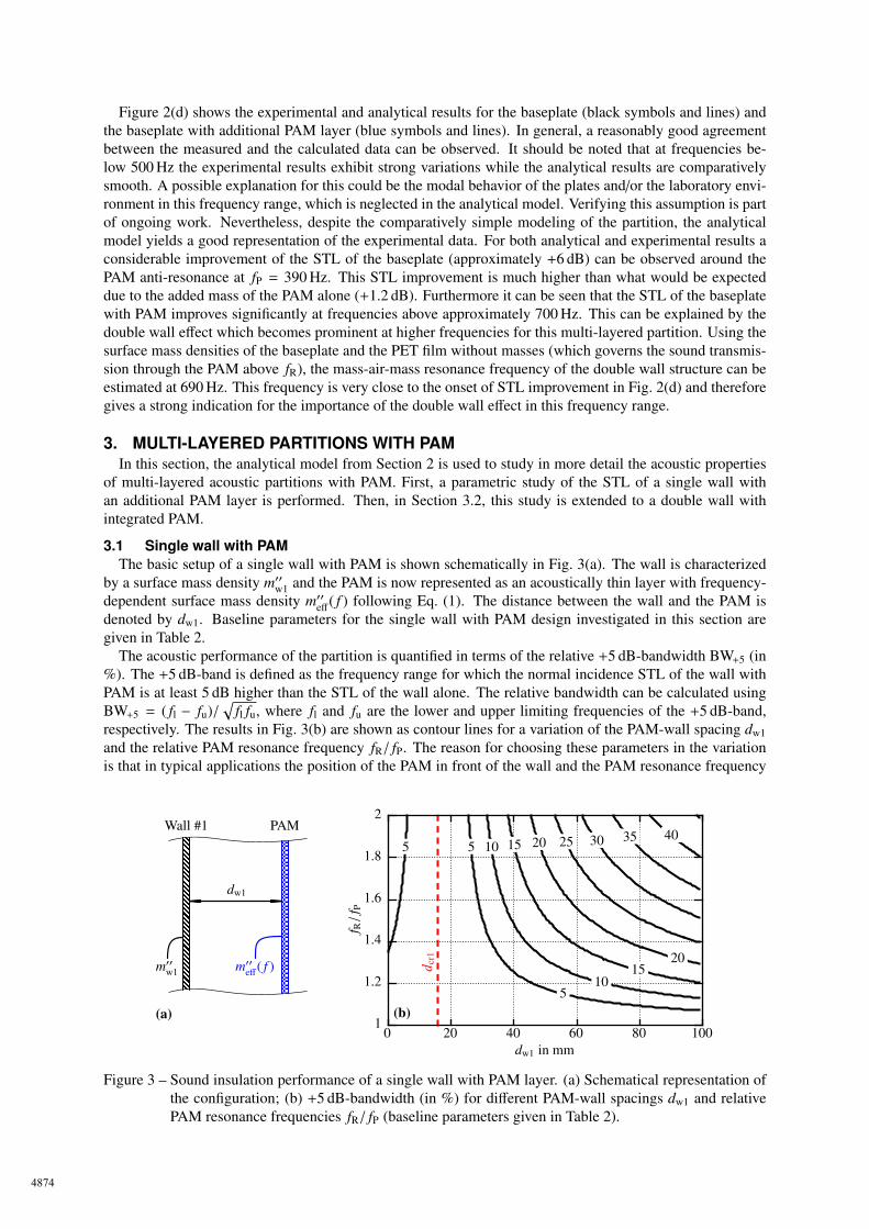
Figure 2(d) shows the experimental and analytical results for the baseplate (black symbols and lines) andthe baseplate with additional PAM layer (blue symbols and lines). In general, a reasonably good agreementbetween the measured and the calculated data can be observed. It should be noted that at frequencies be-low 500 Hz the experimental results exhibit strong variations while the analytical results are comparativelysmooth. A possible explanation for this could be the modal behavior of the plates and/or the laboratory envi-ronment in this frequency range, which is neglected in the analytical model. Verifying this assumption is partof ongoing work. Nevertheless, despite the comparatively simple modeling of the partition, the analyticalmodel yields a good representation of the experimental data. For both analytical and experimental results aconsiderable improvement of the STL of the baseplate (approximately +6 dB) can be observed around thePAM anti-resonance at fP = 390 Hz. This STL improvement is much higher than what would be expecteddue to the added mass of the PAM alone (+1.2 dB). Furthermore it can be seen that the STL of the baseplatewith PAM improves significantly at frequencies above approximately 700 Hz. This can be explained by thedouble wall effect which becomes prominent at higher frequencies for this multi-layered partition. Using thesurface mass densities of the baseplate and the PET film without masses (which governs the sound transmis-sion through the PAM above fR), the mass-air-mass resonance frequency of the double wall structure can beestimated at 690 Hz. This frequency is very close to the onset of STL improvement in Fig. 2(d) and thereforegives a strong indication for the importance of the double wall effect in this frequency range.
3. MULTI-LAYERED PARTITIONS WITH PAMIn this section, the analytical model from Section 2 is used to study in more detail the acoustic properties
of multi-layered acoustic partitions with PAM. First, a parametric study of the STL of a single wall withan additional PAM layer is performed. Then, in Section 3.2, this study is extended to a double wall withintegrated PAM.
3.1 Single wall with PAMThe basic setup of a single wall with PAM is shown schematically in Fig. 3(a). The wall is characterized
by a surface mass density m′′w1 and the PAM is now represented as an acoustically thin layer with frequency-dependent surface mass density m′′eff
( f ) following Eq. (1). The distance between the wall and the PAM isdenoted by dw1. Baseline parameters for the single wall with PAM design investigated in this section aregiven in Table 2.
The acoustic performance of the partition is quantified in terms of the relative +5 dB-bandwidth BW+5 (in%). The +5 dB-band is defined as the frequency range for which the normal incidence STL of the wall withPAM is at least 5 dB higher than the STL of the wall alone. The relative bandwidth can be calculated usingBW+5 = ( fl − fu)/
√fl fu, where fl and fu are the lower and upper limiting frequencies of the +5 dB-band,
respectively. The results in Fig. 3(b) are shown as contour lines for a variation of the PAM-wall spacing dw1and the relative PAM resonance frequency fR/ fP. The reason for choosing these parameters in the variationis that in typical applications the position of the PAM in front of the wall and the PAM resonance frequency
(a)
m′′w1
Wall #1 PAM
dw1
m′′eff( f ) d c
r1
(b)
40353025
20
20
15
15
10
10
5
55
0 20 40 60 80 100dw1 in mm
1
1.2
1.4
1.6
1.8
2
f R/
f P
Figure 3 – Sound insulation performance of a single wall with PAM layer. (a) Schematical representation ofthe configuration; (b) +5 dB-bandwidth (in %) for different PAM-wall spacings dw1 and relativePAM resonance frequencies fR/ fP (baseline parameters given in Table 2).
4874
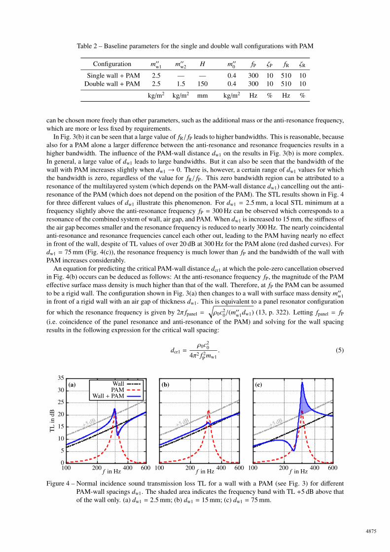
Table 2 – Baseline parameters for the single and double wall configurations with PAM
Configuration m′′w1 m′′w2 H m′′0 fP ζP fR ζR
Single wall + PAM 2.5 — — 0.4 300 10 510 10Double wall + PAM 2.5 1.5 150 0.4 300 10 510 10
kg/m2 kg/m2 mm kg/m2 Hz % Hz %
can be chosen more freely than other parameters, such as the additional mass or the anti-resonance frequency,which are more or less fixed by requirements.
In Fig. 3(b) it can be seen that a large value of fR/ fP leads to higher bandwidths. This is reasonable, becausealso for a PAM alone a larger difference between the anti-resonance and resonance frequencies results in ahigher bandwidth. The influence of the PAM-wall distance dw1 on the results in Fig. 3(b) is more complex.In general, a large value of dw1 leads to large bandwidths. But it can also be seen that the bandwidth of thewall with PAM increases slightly when dw1 → 0. There is, however, a certain range of dw1 values for whichthe bandwidth is zero, regardless of the value for fR/ fP. This zero bandwidth region can be attributed to aresonance of the multilayered system (which depends on the PAM-wall distance dw1) cancelling out the anti-resonance of the PAM (which does not depend on the position of the PAM). The STL results shown in Fig. 4for three different values of dw1 illustrate this phenomenon. For dw1 = 2.5 mm, a local STL minimum at afrequency slightly above the anti-resonance frequency fP = 300 Hz can be observed which corresponds to aresonance of the combined system of wall, air gap, and PAM. When dw1 is increased to 15 mm, the stiffness ofthe air gap becomes smaller and the resonance frequency is reduced to nearly 300 Hz. The nearly coincidentalanti-resonance and resonance frequencies cancel each other out, leading to the PAM having nearly no effectin front of the wall, despite of TL values of over 20 dB at 300 Hz for the PAM alone (red dashed curves). Fordw1 = 75 mm (Fig. 4(c)), the resonance frequency is much lower than fP and the bandwidth of the wall withPAM increases considerably.
An equation for predicting the critical PAM-wall distance dcr1 at which the pole-zero cancellation observedin Fig. 4(b) occurs can be deduced as follows: At the anti-resonance frequency fP, the magnitude of the PAMeffective surface mass density is much higher than that of the wall. Therefore, at fP the PAM can be assumedto be a rigid wall. The configuration shown in Fig. 3(a) then changes to a wall with surface mass density m′′w1in front of a rigid wall with an air gap of thickness dw1. This is equivalent to a panel resonator configuration
for which the resonance frequency is given by 2π fpanel =
√ρ0c2
0/(m′′w1dw1) (13, p. 322). Letting fpanel = fP
(i.e. coincidence of the panel resonance and anti-resonance of the PAM) and solving for the wall spacingresults in the following expression for the critical wall spacing:
dcr1 =ρ0c2
0
4π2 f 2P mw1
. (5)
0
5
10
15
20
25
30
35
200 400 600100
(a)
+5 dB
TL
indB
f in Hz
WallPAM
Wall + PAM
200 400 600100
(b)
+5 dB
f in Hz 200 400 600100
(c)
+5 dB
f in Hz
Figure 4 – Normal incidence sound transmission loss TL for a wall with a PAM (see Fig. 3) for differentPAM-wall spacings dw1. The shaded area indicates the frequency band with TL +5 dB above thatof the wall only. (a) dw1 = 2.5 mm; (b) dw1 = 15 mm; (c) dw1 = 75 mm.
4875
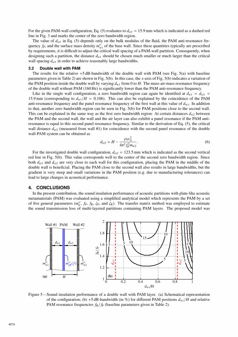
For the given PAM-wall configuration, Eq. (5) evaluates to dcr1 = 15.9 mm which is indicated as a dashed redline in Fig. 3 and marks the center of the zero bandwidth region.
The value of dcr1 in Eq. (5) depends only on the bulk modulus of the fluid, the PAM anti-resonance fre-quency fP, and the surface mass density m′′w1 of the base wall. Since these quantities typically are prescribedby requirements, it is difficult to adjust the critical wall spacing of a PAM-wall partition. Consequently, whendesigning such a partition, the distance dw1 should be chosen much smaller or much larger than the criticalwall spacing dcr1 in order to achieve reasonably large bandwidths.
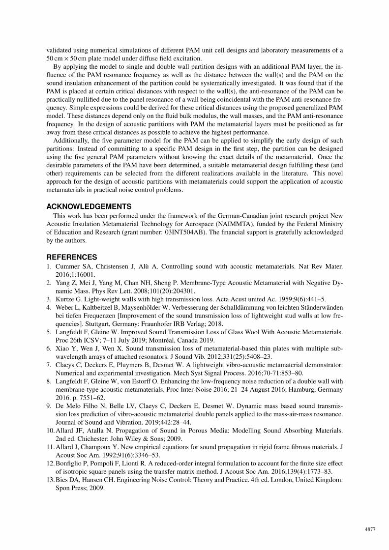
3.2 Double wall with PAMThe results for the relative +5 dB-bandwidth of the double wall with PAM (see Fig. 5(a) with baseline
parameters given in Table 2) are shown in Fig. 5(b). In this case, the x-axis of Fig. 5(b) indicates a variation ofthe PAM position inside the double wall by varying dw1 from 0 to H. The mass-air-mass resonance frequencyof the double wall without PAM (160 Hz) is significantly lower than the PAM anti-resonance frequency.
Like in the single wall configuration, a zero bandwidth region can again be identified at dw1 = dcr1 =
15.9 mm (corresponding to dw1/H = 0.106). This can also be explained by the coincidence of the PAManti-resonance frequency and the panel resonance frequency of the first wall at this value of dw1. In additionto that, another zero bandwidth region can be seen in Fig. 5(b) for PAM positions close to the second wall.This can be explained in the same way as the first zero bandwidth region: At certain distances dw2 betweenthe PAM and the second wall, the wall and the air layer can also exhibit a panel resonance if the PAM anti-resonance is equal to this second panel resonance frequency. Similar to the derivation of Eq. (5), the criticalwall distance dcr2 (measured from wall #1) for coincidence with the second panel resonance of the doublewall-PAM system can be obtained as
dcr2 = H −ρ0c2
0
4π2 f 2P mw2
. (6)
For the investigated double wall configuration, dcr2 = 123.5 mm which is indicated as the second verticalred line in Fig. 5(b). This value corresponds well to the center of the second zero bandwidth region. Sinceboth dcr1 and dcr2 are very close to each wall for this configuration, placing the PAM in the middle of thedouble wall is beneficial. Placing the PAM close to the second wall also results in large bandwidths, but thegradient is very steep and small variations in the PAM position (e.g. due to manufacturing tolerances) canlead to large changes in acoustical performance.
4. CONCLUSIONSIn the present contribution, the sound insulation performance of acoustic partitions with plate-like acoustic
metamaterials (PAM) was evaluated using a simplified analytical model which represents the PAM by a setof five general parameters (m′′0 , fP, fR, ζP, and ζR). The transfer matrix method was employed to estimatethe sound transmission loss of multi-layered partitions containing PAM layers. The proposed model was
m′′w1
(a)
m′′eff( f )
Wall #1 PAM
dw1
H
Wall #2
dw2
m′′w2 d cr1
(b)
d cr2
15
15
10
10
10
55
55
0 0.2 0.4 0.6 0.8 1dw1/H
1
1.2
1.4
1.6
1.8
2
f R/
f P
Figure 5 – Sound insulation performance of a double wall with PAM layer. (a) Schematical representationof the configuration; (b) +5 dB-bandwidth (in %) for different PAM positions dw1/H and relativePAM resonance frequencies fR/ fP (baseline parameters given in Table 2).
4876
validated using numerical simulations of different PAM unit cell designs and laboratory measurements of a50 cm × 50 cm plate model under diffuse field excitation.
By applying the model to single and double wall partition designs with an additional PAM layer, the in-fluence of the PAM resonance frequency as well as the distance between the wall(s) and the PAM on thesound insulation enhancement of the partition could be systematically investigated. It was found that if thePAM is placed at certain critical distances with respect to the wall(s), the anti-resonance of the PAM can bepractically nullified due to the panel resonance of a wall being coincidental with the PAM anti-resonance fre-quency. Simple expressions could be derived for these critical distances using the proposed generalized PAMmodel. These distances depend only on the fluid bulk modulus, the wall masses, and the PAM anti-resonancefrequency. In the design of acoustic partitions with PAM the metamaterial layers must be positioned as faraway from these critical distances as possible to achieve the highest performance.
Additionally, the five parameter model for the PAM can be applied to simplify the early design of suchpartitions: Instead of committing to a specific PAM design in the first step, the partition can be designedusing the five general PAM parameters without knowing the exact details of the metamaterial. Once thedesirable parameters of the PAM have been determined, a suitable metamaterial design fulfilling these (andother) requirements can be selected from the different realizations available in the literature. This novelapproach for the design of acoustic partitions with metamaterials could support the application of acousticmetamaterials in practical noise control problems.
ACKNOWLEDGEMENTSThis work has been performed under the framework of the German-Canadian joint research project New
Acoustic Insulation Metamaterial Technology for Aerospace (NAIMMTA), funded by the Federal Ministryof Education and Research (grant number: 03INT504AB). The financial support is gratefully acknowledgedby the authors.
REFERENCES1. Cummer SA, Christensen J, Alù A. Controlling sound with acoustic metamaterials. Nat Rev Mater.
2016;1:16001.2. Yang Z, Mei J, Yang M, Chan NH, Sheng P. Membrane-Type Acoustic Metamaterial with Negative Dy-
namic Mass. Phys Rev Lett. 2008;101(20):204301.3. Kurtze G. Light-weight walls with high transmission loss. Acta Acust united Ac. 1959;9(6):441–5.4. Weber L, Kaltbeitzel B, Maysenhölder W. Verbesserung der Schalldämmung von leichten Ständerwänden
bei tiefen Frequenzen [Improvement of the sound transmission loss of lightweight stud walls at low fre-quencies]. Stuttgart, Germany: Fraunhofer IRB Verlag; 2018.
5. Langfeldt F, Gleine W. Improved Sound Transmission Loss of Glass Wool With Acoustic Metamaterials.Proc 26th ICSV; 7–11 July 2019; Montréal, Canada 2019.
6. Xiao Y, Wen J, Wen X. Sound transmission loss of metamaterial-based thin plates with multiple sub-wavelength arrays of attached resonators. J Sound Vib. 2012;331(25):5408–23.
7. Claeys C, Deckers E, Pluymers B, Desmet W. A lightweight vibro-acoustic metamaterial demonstrator:Numerical and experimental investigation. Mech Syst Signal Process. 2016;70-71:853–80.
8. Langfeldt F, Gleine W, von Estorff O. Enhancing the low-frequency noise reduction of a double wall withmembrane-type acoustic metamaterials. Proc Inter-Noise 2016; 21–24 August 2016; Hamburg, Germany2016. p. 7551–62.
9. De Melo Filho N, Belle LV, Claeys C, Deckers E, Desmet W. Dynamic mass based sound transmis-sion loss prediction of vibro-acoustic metamaterial double panels applied to the mass-air-mass resonance.Journal of Sound and Vibration. 2019;442:28–44.
10.Allard JF, Atalla N. Propagation of Sound in Porous Media: Modelling Sound Absorbing Materials.2nd ed. Chichester: John Wiley & Sons; 2009.
11.Allard J, Champoux Y. New empirical equations for sound propagation in rigid frame fibrous materials. JAcoust Soc Am. 1992;91(6):3346–53.
12.Bonfiglio P, Pompoli F, Lionti R. A reduced-order integral formulation to account for the finite size effectof isotropic square panels using the transfer matrix method. J Acoust Soc Am. 2016;139(4):1773–83.
13.Bies DA, Hansen CH. Engineering Noise Control: Theory and Practice. 4th ed. London, United Kingdom:Spon Press; 2009.
4877