numerical investigation of aeroacoustic sound sources...
TRANSCRIPT

Numerical Investigation of Aeroacoustic Sound Sources in Encapsulated Helicopter Tail Rotor
Jae Hun You, Christian Breitsamter Institute of Aerodynamics and Fluid Mechanics, Technische Universität München
85748 Garching, Germany, Email: [email protected]
Introduction Reduction of noise levels in order to comply with the civil noise certification rules that is becoming increasingly strict is one of the most important issues confronting helicopter manufactures today. For instance, the FAA (Federal Avia-tion Administration) has recently proposed more stringent noise certification standards requiring new helicopter design that is quieter than current helicopters [1].
Beside of main rotor and turbine engine, tail rotor is one of the major noise contributors to the overall helicopter noise signature for a conventional helicopter configuration. There are two approaches to design the tail rotor: conventional open tail rotor and encapsulated tail rotor. The encapsulated tail rotor, well-known as Fenestron®, is a multi-bladed fan embedded in a helicopter vertical fin. Hence, a duct-fairing encloses fan rotor and protects the rotor blade against colli-sions with ground obstacles.
In contrast to the open tail rotor, the Fenestron® also reveals significant advantages in terms of low noise emission [2]. The duct-fairing primarily provides an acoustic masking effect occasioning low noise radiation, especially, in the plane of blade rotation. The multi-blade configuration also leads to low noise power emission as a result of reduced tangential velocity of the blade tip. Furthermore, the latest generation of Fenestron® features modulated blade spacing in order to suppress shrill noise, which relates to the discrete noise at the blade passing frequency (BPF) and correspond-ing harmonics.
Although the Fenestron® has confirmed as a successful solu-tion to quiet tail rotor design, due to the reasons mentioned above, further aeroacoustic researches into the noise genera-tion mechanisms of the shrouded tail rotor are still required to improve the Fenestron® acoustic characteristics.
In this context, the present research addresses the numerical analysis of Fenestron® aeroacoustic properties for more in-depth understanding of flow induced noise in cruise flight. In the present study, a hybrid methodology is employed for the acoustic noise analysis. Hereby, the aerodynamic noise sources of the Fenestron® are captured with CFD (Computa-tional Fluid Dynamics) approach by using the Unsteady Reynolds Averaged Navier-Stokes (URANS) method. Two different turbulence models, the Shear Stress Transport (SST) model and the Scale Adaptive Simulation (SAS) mod-el, are employed to assess the noise-prediction capabilities of the hybrid approach applied herein with respect to the ap-proximation order of turbulent flow modelling.
The source information from the flow analysis is then used to calculate the radiated far-field sound by using the Ffowcs Williams and Hawkings (FW-H) surface integral method.
Methods Investigated Geometry The geometry regarded herein is a full scale (1:1) light weight transport helicopter configuration with an encapsu-lated tail rotor. The complete helicopter geometry is here used except the main rotor and the skid landing gear (Fig. 1 (a)). Thus, the present study does not consider the down wash effect of the main rotor, as well as the tail rotor-main rotor vortex interaction. It is assumed that the effects do not dominate the Fenestron® forward flight condition regarded herein. The Fenestron® part is composed of 10 rotor blades with the modulated blade spacing and 10 evenly distributed vanes in the stator. A multi-block structured mesh (3400 blocks, 27.3 million nodes for SST simulation) is generated on the geometry by using ICEM CFD (Fig. 1(b)).
CFD Simulations The first step of the hybrid approach is the computation of the unsteady compressible flow field related to the acoustic source regions. For this purpose, URANS simulations are performed with the ANSYS CFX commercial flow solver, which is based on a finite volume discretization.
(a)
(b)
Figure 1: (a) Investigated helicopter configuration; (b) Block structured mesh topology (perspective from the fan inlet side).
Fin & Duct-fairing Tailboom
Stator Rotor Empennage Fuselage
Local mesh refinement for SAS model
AIA-DAGA 2013 Merano
1933

The rotation of the blades is modelled by applying the slid-ing mesh method [3]. Hereby, the rotor blade rotates one degree per numerical time step Δt (360 time steps for a sin-gle fan revolution).
Two different turbulence models are employed for unsteady simulations: the k-ω SST model [3, 4] and the SAS model [3, 5]. The k-ω SST model is a two equation eddy-viscosity model combining the k-ω model and k-ε model in order to take advantages of each formulation in the certain flow re-gion (e. g. the k-ω model for the boundary layer and the k-ε formulation for the free stream). Hereby, switching of for-mulation is achieved by a special blending function based on the wall distance. Although the k-ω SST model has been acknowledged as a recommendable turbulence model for (U)RANS simulations to predict complex flow fields involv-ing flow separation [6], (U)RANS simulations with the k-ω SST formulation are in general incapable to reproduce small-scale eddies containing spectral contents at high frequencies due to the time averaging manner of the RANS formulation.
The SAS model is an advanced URANS formulation which can resolve spectral contents of unstable flow up to almost grid limitation. This scale resolving turbulence model is based on the introduction of an additional term involving the von Kárman length scale, LνK, into the transport equation for the turbulence eddy frequency. Hereby, the unsteadiness of flow is detected by the increase of the ratio of the modelled turbulent length scale, L, to LνK. If the flow region reveals sufficient occurrence of unsteadiness with increasing L / LνK the SAS approach is switching from a stable RANS mode (here with the SST model) to an unsteady mode that results in decreasing of turbulence viscosity, μt. In this way, a LES-like resolution of turbulent eddies can be provided in the unsteady flow region.
Depending on the turbulence model two different spatial discretization schemes are applied. The High Resolution scheme [3] used for the SST simulation allows a dynamical adjustment of robustness (1st order upwind) and accuracy (2nd order upwind) of the numerical solution controlled by a blending factor. For the SAS simulation, the Bounded Cen-tral Difference (BCD) scheme [3] is employed to avoid un-desirable oscillations of the Central Difference (CD) scheme, which could in turn lead to generating non-physical wiggles in the flow field.
Totally, 10 fan revolutions corresponding to a physical time of 176 ms are computed for both turbulence models. The transient data, which contains the flow quantities, such as velocity field, density and static pressure are stored for every three CFD time steps. These values serve as the source input for the subsequent acoustic calculation.
CAA Calculations In the present work, the FW-H formulation modified by Farassat (Formulation 1 of Farassat) [7] is adopted for a porous control surface in stationary motion. According to this formulation, the radiated sound pressure can be divided into three sub-terms consisting of thickness noise, Tp , load-ing noise, Lp , and quadrupole noise, Qp , as presented in equation (1).
),(),(),(),( txptxptxptxp QLT [pa] (1)
The FW-H code implemented herein does not involve the quadrupole noise term in the equation (1), since it requires a volume integral in the FW-H equation that is impractical for such complex, three dimensional flow problems. The contri-bution of the quadrupole source to the total noise is thus implicitly taken into account in such a way as to take a suit-able integral surface that is sufficiently far from the Fenes-tron® solid surfaces in order to enclose the volumetric noise source. Thus, two disconnected hemispherical integral sur-faces located on the fan inlet and fan outlet side, respective-ly, are used in the present study.
However, it is observed that vortical structures originating from the helicopter aft body move through the permeable integral surface as illustrated in Fig. 2 (a). It could generate undesirable, non-physical sound as reported in Ref. [8]. To examine the effect of this vortex-integral surface interaction onto the accuracy of noise prediction, a test simulation is conducted with the SST turbulence model. Hereby, the iden-tical helicopter geometry, but without the Fenestron® fan, is considered (Fig. 2 (b)). As shown in Fig. 2 (c), the interac-tion leads to generating artificial sound level, however, only over a narrow range of frequencies, which are far below the fundamental frequency of interest in the present work. Therefore, the BPF and its corresponding harmonics are not affected by the interaction.
(a)
(b)
(c)
Figure 2: Vortical structure-permeable integral surface in-teraction for helicopter configuration (a) with the Fenes-tron® fan, (b) without fan and (c) corresponding sound pressure spectrum.
Soun
d pr
essu
re le
vel [
dB]
Integral surface Integral surface
1st BPF
20 dB
Frequency [Hz]
AIA-DAGA 2013 Merano
1934
Results and Discussion CFD Simulations In Fig. 3 (a) and (b), turbulent structures around the helicop-ter fuselage, predicted with the SST and the SAS simulations are visualized by means of isosurfaces of the Q-criterion (Q=Ω2–S2, where Ω is the absolute value of vorticity and S is the absolute value of shear strain rate). Additionally, the isosurfaces are colored with the ratio of the modelled turbu-lent viscosity μt to the molecular dynamic viscosity, μ, de-noted as eddy viscosity ratio, μt /μ. As illustrated in Fig. 3 (a) and (b), the wake region of the helicopter fuselage reveals a highly disrupted flow field in cruise flight. It is provoked by a massive flow separation occurring at the different parts of the fuselage (lower fuselage aft body, sealed engine inlet, engine exhaust and rotor mast fairing). Thus, the Fenestron® in turn operates under highly perturbed flow conditions. Comparing the turbulent structures in the region of separated flow reveals that the SAS approach produces resolved scales of vortical structures with significantly lower ratios of μt /μ, whereas the SST simulation predicts comparably large scale vortical structures with remarkable higher ratios of μt /μ. However, with the SAS model, the attached boundary layer at the front fuselage section is treated by the SST formula-tion. In this relatively stable flow region almost identical magnitudes of the turbulent viscosity are computed with both the SST and the SAS simulation.
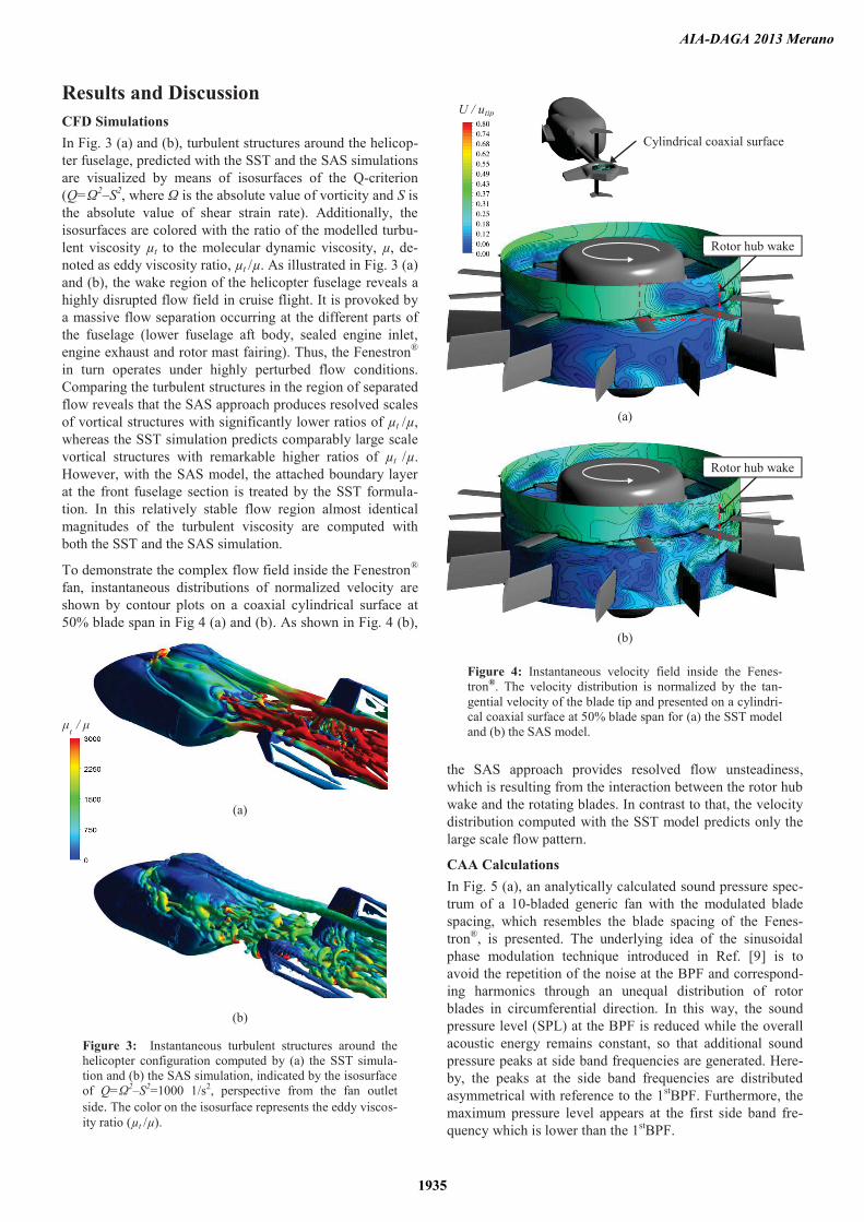
To demonstrate the complex flow field inside the Fenestron® fan, instantaneous distributions of normalized velocity are shown by contour plots on a coaxial cylindrical surface at 50% blade span in Fig 4 (a) and (b). As shown in Fig. 4 (b),
the SAS approach provides resolved flow unsteadiness, which is resulting from the interaction between the rotor hub wake and the rotating blades. In contrast to that, the velocity distribution computed with the SST model predicts only the large scale flow pattern.
CAA Calculations In Fig. 5 (a), an analytically calculated sound pressure spec-trum of a 10-bladed generic fan with the modulated blade spacing, which resembles the blade spacing of the Fenes-tron®, is presented. The underlying idea of the sinusoidal phase modulation technique introduced in Ref. [9] is to avoid the repetition of the noise at the BPF and correspond-ing harmonics through an unequal distribution of rotor blades in circumferential direction. In this way, the sound pressure level (SPL) at the BPF is reduced while the overall acoustic energy remains constant, so that additional sound pressure peaks at side band frequencies are generated. Here-by, the peaks at the side band frequencies are distributed asymmetrical with reference to the 1stBPF. Furthermore, the maximum pressure level appears at the first side band fre-quency which is lower than the 1stBPF.
(a)
(b)
Figure 4: Instantaneous velocity field inside the Fenes-tron®. The velocity distribution is normalized by the tan-gential velocity of the blade tip and presented on a cylindri-cal coaxial surface at 50% blade span for (a) the SST model and (b) the SAS model.
(a)
(b)
Figure 3: Instantaneous turbulent structures around the helicopter configuration computed by (a) the SST simula-tion and (b) the SAS simulation, indicated by the isosurface of Q=Ω2–S2=1000 1/s2, perspective from the fan outlet side. The color on the isosurface represents the eddy viscos-ity ratio (μt /μ).
Cylindrical coaxial surface
Rotor hub wake
Rotor hub wake
U / utip
μt
/ μ
AIA-DAGA 2013 Merano
1935
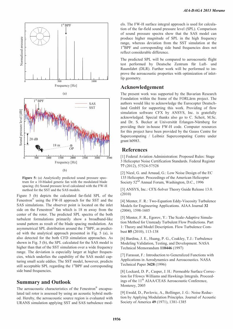
Figure 5 (b) depicts the calculated far-field SPL of the Fenestron® using the FW-H approach for the SST and the SAS simulations. The observer point is located on the inlet side on the Fenestron® fan which is 18 m away from the center of the rotor. The predicted SPL spectra of the both turbulent formulations primarily show a broadband-like sound pattern as result of the blade spacing modulation. An asymmetrical SPL distribution around the 1stBPF, as predict-ed with the analytical approach presented in Fig. 5 (a), is also detected for the both CFD simulation approaches. As shown in Fig. 5 (b), the SPL calculated for the SAS model is higher than that of the SST simulation over a wide frequency range. The deviation is especially larger at higher frequen-cies, which underlies the capability of the SAS model cap-turing small scale eddies. The SST model, however, predicts still acceptable SPL regarding the 1stBPF and corresponding side band frequencies.
Summary and Outlook The aeroacoustic characteristics of the Fenestron® encapsu-lated tail rotor is assessed by using an acoustic hybrid meth-od. Hereby, the aeroacoustic source region is evaluated with URANS simulation applying SST and SAS turbulence mod-
els. The FW-H surface integral approach is used for calcula-tion of the far-field sound pressure level (SPL). Comparison of sound pressure spectra show that the SAS model can produce higher magnitude of SPL in the high frequency range, whereas deviation from the SST simulation at the 1stBPF and corresponding side band frequencies does not reflect considerable difference.
The predicted SPL will be compared to aeroacoustic flight test performed by Deutsche Zentrum für Luft- und Raumfahrt (DLR). Further work will be performed to im-prove the aeroacoustic properties with optimization of inlet-lip geometry.
Acknowledgement The present work was supported by the Bavarian Research Foundation within the frame of the FORLärm project. The authors would like to acknowledge the Eurocopter Deutsch-land GmbH for supporting this work. Providing of flow simulation software CFX by ANSYS, Inc. is gratefully acknowledged. Special thanks also go to C. Scheit, M.Sc. and Dr. S. Becker at Universität Erlangen-Nürnberg for providing their in-house FW-H code. Computer resources for this project have been provided by the Gauss Centre for Supercomputing / Leibniz Supercomputing Centre under grant h0983.
References [1] Federal Aviation Administration: Proposed Rules: Stage 3 Helicopter Noise Certification Standards. Federal Register 77 (2012), 57524-57528
[2] Niesl, G. and Arnaud, G.: Low Noise Design of the EC 135 Helicopter. Proceedings of the American Helicopter Society 52nd Annual Forum, Washington, D.C., 1996
[3] ANSYS, Inc.: CFX-Solver Theory Guide Release 13.0. (2010)
[4] Menter, F. R.: Two-Equation Eddy-Viscosity Turbulence Models for Engineering Applications. AIAA Journal 32 (2004), 1598-1605
[5] Menter, F. R., Egorov, Y.: The Scale-Adaptive Simula-tion Method for Unsteady Turbulent Flow Predictions. Part 1: Theory and Model Description. Flow Turbulence Com-bust 85 (2010), 113-138
[6] Bardina, J. E., Huang, P. G., Coakley, T.J.: Turbulence Modeling Validation, Testing, and Development. NASA Technical Memorandum 110446 (1997)
[7] Farassat, F.: Introduction to Generalized Functions with Applications in Aerodynamics and Aeroacoustics. NASA Technical Paper 3428 (1996)
[8] Lockard, D. P., Casper, J. H.: Permeable Surface Correc-tion for Ffowcs Williams and Hawkings Integrals. Proceed-ings of the 11th AIAA/CEAS Aeroacoustic Conference, Monterey, 2005
[9] Ewald, D., Pavlovic, A., Bollinger, J. G.: Noise Reduc-tion by Applying Modulation Principles. Journal of Acoustic Society of America 49 (1971), 1381-1385
(a)
(b)
Figure 5: (a) Analytically predicted sound pressure spec-trum for a 10-bladed generic fan with the modulated blade spacing; (b) Sound pressure level calculated with the FW-H method for the SST and the SAS models.
20 dB
1st BPF
1st BPF
18 m OP
Nor
mal
ized
pre
ssur
e So
und
pres
sure
leve
l [dB
]
Frequency [Hz]
Frequency [Hz]
SAS SST
AIA-DAGA 2013 Merano
1936