design of a reinforced-concrete arch - illinois: ideals home
TRANSCRIPT

THE UNIVERSITY
OF ILLINOIS
LIBRARY


Digitized by the Internet Archive
in 2013
http://archive.org/details/designofreinforcOOrund

DESIGN OFA REINFORCED-CONCRETE ARCH
BY
EARL RUNDLES
THESIS
FOR
DEGREE OF BACHELOR OF SCIENCE
IN
CIVIL ENGINEERING
COLLEGE OF ENGINEERING
UNIVERSITY OF ILLINOIS
1913
Ui\riVEiisiTY oy iLLiisruis
woliege of Engineering.
May 21+, 1913.
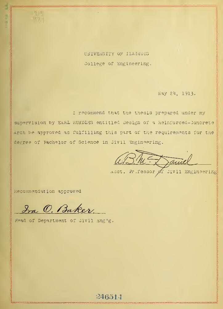
I r?coniinencl tnat the thesis prepared under rny
supervision by earl rukdL-cg entitled Design or a Reinrorced-.:)oncret
e
Arch \'^e approved as fulfilling this part of the requirements for the
degree of Facheior of Science in Jivii Engineering.
Recommendation approved
Head of Department of Jivil Jing'g.
L246514


Table of Contents.
Introduction Page 1
Reinforcement Page 1
Method Page 1
Dimensions Page 2
Amount of Heinforcement Page 2
Loading Page 2
V/eights of IJatf.rial Page 2
Design Page 2
Conclusion Page 7
Tables 1 Page a
II Page 3
III Page /O
Plate I Page //
Plate II
.-§3ros9 Sections of ArchT Pape/-2

UlUC

DESIGIJ OF A {EILFORGEI; C01ICR::TE /RCH.
IIITRODUCTIOII.
Ovi-iTiR to the fact that the regular Uni-
versity curriculum for undergraduate v;ork does not pro-
vide for instruction on the theory and design of arches,
thesis work covering this field was chosen. The arch
herein designed is intended to carry heavy highway traffic.
It has a clear span of ninety-two feet and rise of eleven
feet. '"he small rise was used so as to give ample room
for the flow of flood waters near the haunches of the arch,
REIMFORCEIOIT.
The reinforcement consistfs of square twisted
"bars. Three quarter inch hars,placed six inches apart
were used in the intrados and extrados. One half inch
"bars placed two feet apart were used in the transverse
direction. This system was chosen rather than the Lielan
type in that tests show that a smaller unit gives greater
strength, area for area.
METHOD.
Prof. Baker's graphical method according to
the elastic theory was used in the design. The general
dim.ensions were first assumed nnd then the design worked
out to see v/hether the stresses obtained 7;ere within the
allowable limit. The allowable stresses and the v;eights
of the m.aterial are those v;hich have been generally accepted.

2
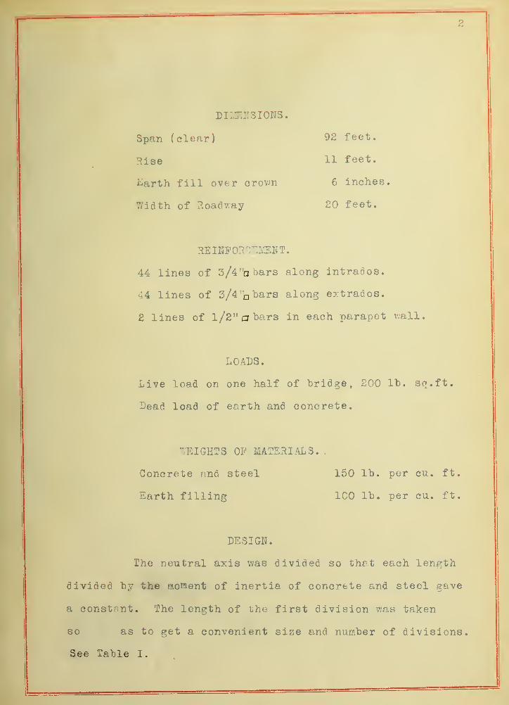
DIIJEIT3I01IS.
Span (clear) 92 feet.
Rise 11 feet,
i^arth fill over crown 6 inches.
Width of Roadway 20 feet,
REIKFOHC^MEKT.
44 lines of 3/4 "a bars along intrados.
44 lines of 3/4 bars along extrados.
2 lines of 1/2" a bars in each parapet wall.
LOADS.
Live load on one half of bridge, 200 lb. sq.ft.
Dead load of earth and concrete.
WEIGHTS Oi' MATERIALS.,
Concrete nnd steel 150 lb. per cu. ft.
Earth filling 100 lb. per cu. ft
DESIGN.
The neutral axis was divided so that each length
divided by the moHient of inertia of concrete and steel gave
a constant. The length of the first division was taken
so as to get a convenient size and number of divisions.
See Table I.
3
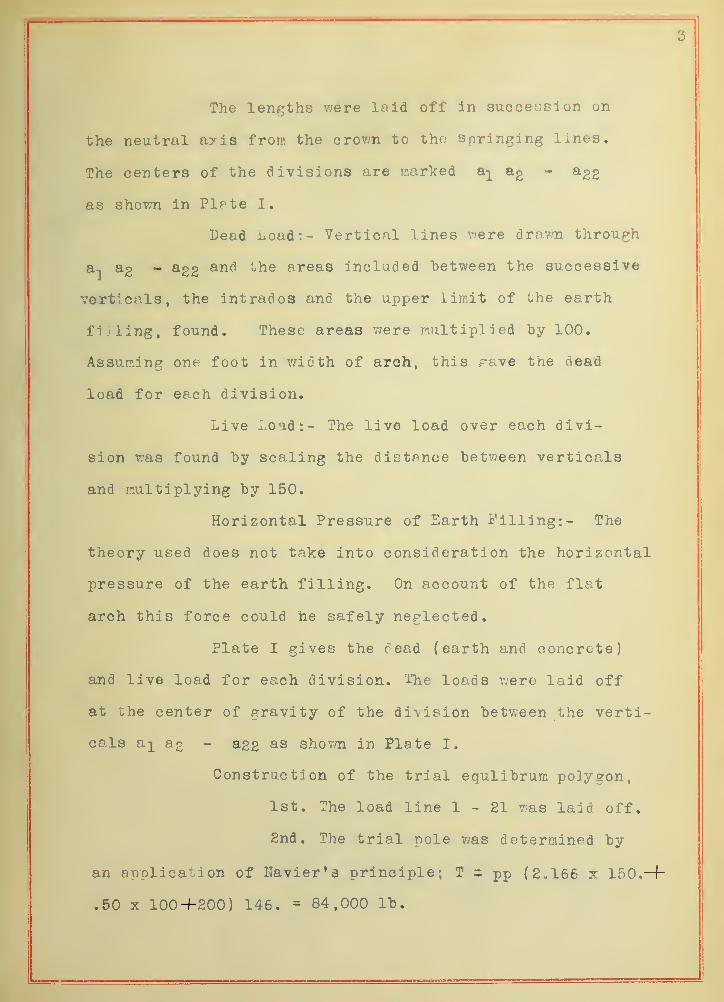
The lengths were laid off In suocecsion on
the neutral axis from the crovm to the springing lines.
The centers of the divisions are marked a;L ®2 ^22
as shown in Plate I,
Dead lioad:- Vertical lines were drawn through
ag - agg and the areas included between the successive
verticals, the intrados and the upper limit of the earth
filling, found. These areas were multiplied by 100.
Assuming one foot in width of arch, this reive the dead
load for each division.
Live Load:- The live load over each divi-
sion was found by scaling the distance between verticals
and multiplying by 150.
Horizontal Pressure of Earth Filling:- The
theory used does not take into consideration the horizontal
pressure of the earth filling. On account of the flat
arch this force could he safely neglected.
Plate I gives the oead (earth and concrete)
and live load for each division, ilie loads were laid off
at Che center of gravity of the division between the verti-
cals a^ ag - agg as shovm in Plate I.
Construction of the trial equlibrum polygon,
1st. The load line 1-21 was laid off.
2nd. The trial pole v/as determined by
an application of Navier'a principle; T - pp (2.166 x 150.-f-
.50 X 100-1-200) 146. - 84,000 lb.

4
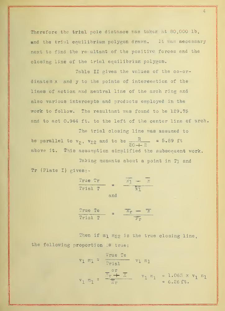
Therefore the trial pole distance v;as taken at 80,000 lb,
^nd the tri il equilibrium polygon drawn. It was necessary
next to find the re^ ultant of the positive forces and the
closing line of the trial equilibrium polygon.
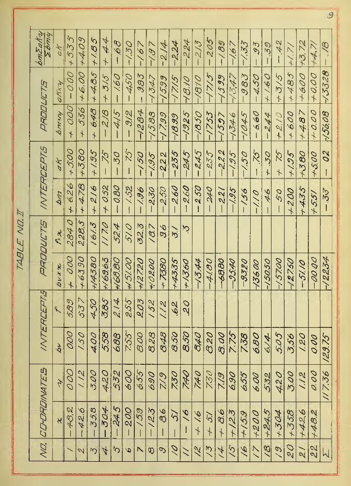
Table II gives the values of the co-or-
dinates x and y to the points of intereection of the
lines of action and neutral line of the arch ring and
also various intercepts and products employed in the
work to follow. The resultant was found to be 129.75
and to act 0.944 ft. to the left of the center line of arch.
The trial closing line was assumed to
be parallel to Vo . Voo and to be 5 = 5.89 ft^ 20-1- 2
above it. This assumption simplified the subsequent work.
Taking monents about a point in Tl and
Tr (Plate I) givest-
True Tr jq" — x
Trial T
and
True Te ^ —Trial T ^Then if mi mgg is the true closing line,
the following proportion .s true:
I'rue Te
^1 ""'1 ~ Tr"^ '^l 1^1'-'rial
^
_ 0^r —f- ^^ V ^
ri-|^ = 1.063 X Y-^ n^^1 ^1 ~ Xr = 6.26 ft.

5
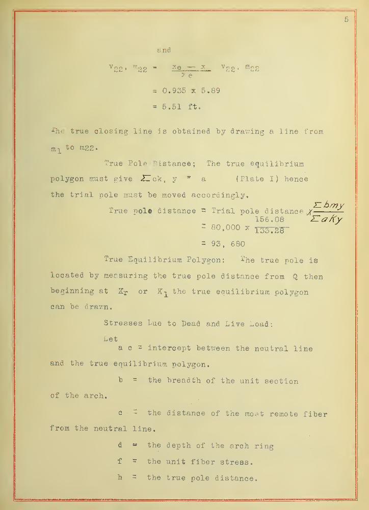
and
^22- "'22 - — ^ vog. m-oy- e
= 0.935 X 5.89
= 5.51 ft.
'•^'hc true closing line is obtained "by drav;ing a line from
n,-|_to m22.
True Pole "Distance; The true etjuilitrium
polygon must give ZTck, y * a (Plate I) hence
the trial pole must "be moved accordingly.
True pole distance = Trial pole distance,/ —156.08 IIa/(y
' GO. 000 X i337g^= 93, 680
True Equilibrium Polygon: The true pole is
located by measuring the true pole distance from Q then
beginning at Xr or K-j^ the true equilibrium polygon
can be drav.'n.
Stresses I>ue to Dead and Live Load:
Leta c = intercept between the neutral line
and the true equilibrium polygon.
b •= the breadth of the unit section
of the arch.
c ~ the distance of the most remote fiber
from the neutral line.
d " the depth of the arch ring
f - the unit fiber stress,
h = the true pole distance.

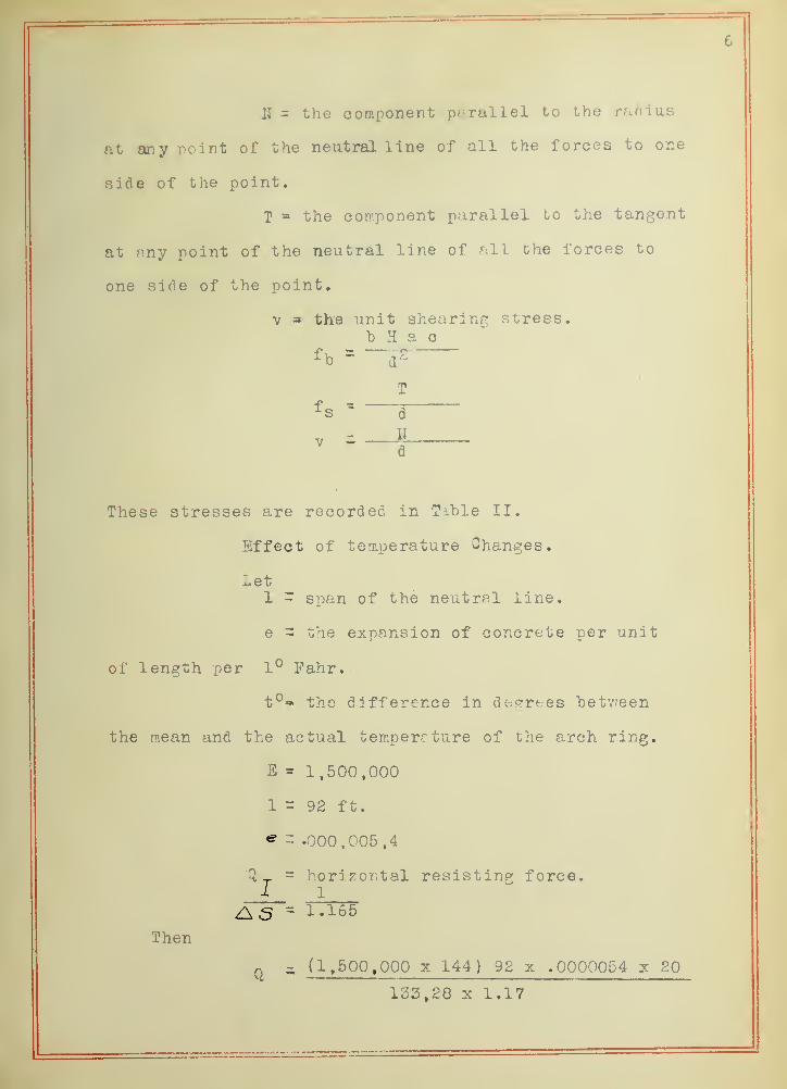
II = the component parallel to the radius
at any point of the neutral line of all the forces to one
side of the point,
T the component parallel to the tangent
at any point of the neutral line of all the forces to
one side of the point,
V » the unit shearing stress,b H a c
fh =~
T
^s d
These stresses are recorded in Tible II.
Effect of temperature Changes.
LetX - span of the neutral line,
e = the expansion of concrete per unit
of length per 1° Fahr.
t°- the difference in de^'rees hetv/een
the mean and the actual temperature of the arch ring,
E = 1,500,000
a = 92 ft.
^-.000,005,4
I= horizontal resisting force.
Then
Z\s = 1.165
Q - (1,500,000 X 144) 92 x ,0000054 x 20
133,28 X 1.17

7
a 1840'
^ = ^ y 1040 X 5. = 4930%' or 34^'3.352
Concliision:- Table III shoY.'S the stresses due
to clead and live loads. The stresses use(? irj checking
the' design of the arch ring are the maximum jtresses v/hich
occur at the points shovm in the tr.hle. The shearing
stress Ft most points ras almost negligable being too
sm.all to measure by graphical methods.

X N\
NO
\ \X X
M)XX
XX
XCM
X
XXX
<\
Am.
NON CM
nO
s
N CM
CMCMX •M
CO
OM CM
CM
CM CN/
f\ 1
oo
CM"
XCM
«)IV)
^:
^/^ rv\)
x\
CM
X
on
X X X
>NO\ \
(5\1
CM
CM
cm"
CM
CMCO
CM
1CM <0 0)

3
1 1
00
1
X1
N
X1
N
1
CM
1 1 1
00
X1
\X
1 r 11
1
XtX
1
1
<<>>
OQ
1
11
CO
1 > > > >
X
1> >
oo
1 1
X
1
11
1
oo
> >;qX
1
N NO
>NO"
11
X
i
Is
00
rss)
11
1
IQ
1
\1
1
CM
11 1 1 1 1
X1
\-
1
1
X1
WNO
1
X1
X1
^.
1 1
^'
1 1 1
X
1
x ?1
XX
1 11
Is
tlx
ia;
\iN\\
<^ ho NQOX
X
NT)
> >
rsSJ«0X
1
cs
CO
1
1
fS
X1
1
>
rs
> 11
1
N
CM XXX CM
On U
CO
rsNj rsSJM03
rss^
K
(fS rs\JCMX
1
1
MW
Mi
<^ XX K
?1
1
1
1
1
1
T
1
1
^ }
11
^
11
X1
1
X1
111
1
1
X1
MiX
1 r r >CM
> > >
^X >
s N 00 XX 5i X X ^5XX X X CM
CM

\^0 \
N
1
s>
^ 1 \
N
CM Kn
CM\
k1
CM\
s
in
NT)
T NT V V
C3
\l
N \ K
V
1:1
1Hi 1
PO/NT
^^ ^-^5

UNIVf

.92
•I- 71
-M-y/-
V.<J<
V-fl.7.-<l\\
10:
IJ
,07
1
7.
' . 1
I
1

4
it
4

4
