design of a 10 mev beamline at the upgraded injector test
TRANSCRIPT
DESIGN OF A 10 MeV BEAMLINE AT THE UPGRADED INJECTOR TEST FACILITY FOR e-BEAM IRRADIATION*
X. Li1,2 †, F. Hannon, H. Baumgart1,2, G. Ciovati, S. Wang Thomas Jefferson National Accelerator Facility, Newport News, Virginia, USA
1also at Department of Electrical and Computer Engineering, Old Dominion University, Norfolk, VA, USA
2also at Applied Research Center at Thomas Jefferson National Accelerator Facility, Newport News, VA, USA
Abstract Electron beam irradiation with energy less than or close
to 10 MeV is suitable and sustainable for the wastewater treatment. The Upgraded Injector Test Facility (UITF) at Jefferson lab is a CW superconducting linear accelerator capable of providing an electron beam of energy up to 10 MeV. To investigate degradation of the organic com-pound pollutants, a wastewater treatment beamline at UITF has been designed by using the code GPT (General Particle Tracer). The electron beam is assumed to have 8 MeV elec-tron energy and the transverse radius of sigma around 0.8 to 0.9 cm. It has been found that the rms (by second central moment) energy spread induced by the accelerating cavity is less than 74.5 keV in the simulations. The space charge effect doesn’t affect the beam quality for 100 nA beam cur-rent.
INTRODUCTION With the increasing industrialization affecting the qual-
ity of human life, more and more varieties of harmful in-dustrial organic compounds are found in the wastewater. These toxic organic compounds like 1,4 dioxane are ex-tremely difficult to be removed by existing conventional treatment methods, which challenges the wastewater treat-ment before it is discharged to the surroundings or reused for the replenishment of ground water [1-3]. EB (electron beam) irradiation has been proven to be a sustainable ap-proach for the wastewater treatment, since it is capable of removing efficiently and effectively the most harmful pol-lutants including the toxic chemicals, metal, bacteria, vi-ruses, pathogens, and especially the organic compounds from industrial manufacturing [4, 5].
Since the 1980s when EB irradiation was widely applied in the commercial and industrial fields all over the world, numerous promising research efforts have been reported on wastewater EB irradiation. First of all, EB irradiation is versatile for treating a wide range of pollutants in wastewater. The target chemicals are in an aqueous wastewater, so the energetic electrons, typically between 1 MeV to 10 MeV, interact with the water molecules to pro-duce mainly the reducers, aqueous electron 𝑒 , hydro-gen ∙ 𝐻, and oxidant, hydroxyl ∙ 𝑂𝐻, which then contribute to the removal of the target materials through chemical re-dox reactions [6]. Theoretically EB irradiation is able to
remove any chemicals which can be degraded by a reducer or an oxidant. Various kinds of waste chemicals and micro-organisms are treated at the EBRF (Electron Beam Re-search Facility) of Miami [2, 7] and can be removed at a high percentage with the dose around 8 kGy. Secondly, the EB irradiation is quite safe and friendly to the environment due to the absence of the extra chemicals and the low radi-ation effects of the easily stopped electrons. Finally, EB ir-radiation is able to treat the wastewater at a large-scale. The wastewater is usually treated as a sheet flow in front of the electron beam due to the limited penetration depth of the electrons in the liquid water, so the wastewater can be treated based on the operation status of the electron accel-erator. Therefore, with its non-selectivity, environment friendly and large-scale treatment, EB irradiation can be considered a prospective approach for the modern wastewater treatment.
SWIFT (Sustainable Water Initiative for Tomorrow) is a local program conducted by HRSD (Hampton roads sani-tation district) to slow down and ultimately restore the land subsidence of the Chesapeake Bay with the replenishment of the treated wastewater to the Potomac aquifer [8, 9], where the wastewater is treated to reach drinking water standard level before recycling it to replenish groundwater lost by excessive use. The remediation of the pollutants is usually affected by a lot of factors, such as the electron beam parameters, the pH of the wastewater, the target com-pounds, and the degradation pathways of different chemi-cals are also different. For the purpose of this research pro-ject 1,4-dioxane, a common toxic organic compound in the wastewater, has been designated as the initial target chem-ical. Instead of using flow water, the sample wastewater is going to be irradiated in a special designed sample con-tainer to investigate the degradation mechanism of harmful organic pollutants.
The electron beam is utilized with the UITF in Jefferson lab. The maximum electron energy of UTIF can reach up to 10 MeV, we have investigated research scenarios under several different electron beam energies. As an initial study, 8 MeV electron beam is being used as the first step.
Based on UITF, this paper describes the design of the wastewater treatment beamline, which consists of the pho-tocathode electron gun, transportation magnets, accelerat-ing SRF (super-conducting radio-frequency) cavities and defocusing magnets and the set-up is 25 m long. With the GPT (general particle tracer) simulations [10], we will state designed beam size, the initial electron beam distribution,
___________________________________________
* Work supported by LDRD program in Jefferson lab. † [email protected], [email protected]
12th Int. Particle Acc. Conf. IPAC2021, Campinas, SP, Brazil JACoW PublishingISBN: 978-3-95450-214-1 ISSN: 2673-5490 doi:10.18429/JACoW-IPAC2021-WEPAB254
WEPAB254Con
tent
from
this
wor
km
aybe
used
unde
rthe
term
sof
the
CC
BY
3.0
licen
ce(©
2021
).A
nydi
stri
butio
nof
this
wor
km
ustm
aint
ain
attr
ibut
ion
toth
eau
thor
(s),
title
ofth
ew
ork,
publ
ishe
r,an
dD
OI
3232
MC5: Beam Dynamics and EM Fields
D08 High Intensity in Linear Accelerators - Space Charge, Halos
the RF gradients and phases scanning, the blowing trans-portation. Finally, the space charge effects on the beamline are investigated from beam currents ranging from 100 nA to 100A.
BEAMLINE SETUP With the 10 MeV maximum electron energy of UITF, the
wastewater sample container is designed with 4 cm depth [11]. Taking the 1,4-dioxane concentration detecta-ble volume limit, the volume is around 75 mL and its cor-responding cross section diameter is 2.43 cm. Therefore, the transverse radius of the beam should not be less than 2.43 cm and should ideally have a uniform distribution. The 𝜎 (standard deviation of the beam) range is de-signed from 0.8 to 0.9 cm.
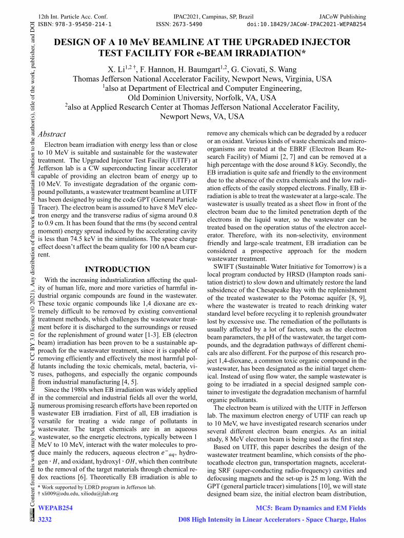
Figure 1 is the schematic of the wastewater treatment beamline.
Figure 1: Schematic of the wastewater treatment beamline.
The laser pulses with 780 nm wavelength are getting ab-sorbed by the photocathode inside the electron gun cavity causing the gun to emit the electrons, which are then accel-erated to 200 keV energy by the electric field in the DC gun and transported through the solenoids, chopper cavity and buncher cavity before reaching the SRF cavities of 1.5 GHz. There are two cavities inside the SRF cryomod-ule, the first one is a 2-cell cavity to capture the electron bunches and to accelerate the bunches to 0.533 MeV, the following 7-cell cavity is to accelerate the electron beam to 8 MeV.
However, the magnetic strengths of the following four quadrupoles are not sufficient to expand the electron beam to a big round beam size within the existing beamline dis-tance less than 10 m. Therefore, they are designed to transport the electron beam to a round one and to achieve the big beam size as much as they can by adjusting the fo-cusing point. Then a solenoid, with peak on axis magnetic strength of 0.23 T, is applied to over-focus the beam to be as small as possible it can to achieve a higher beam diver-gency after the focusing point, which is beneficial to ex-pand the electron beam within the existing beamline dis-tance. Ultimately the electron beam is obtained with a transverse maximum radius of up to 25 mm when it reaches to the sample container.
INITIAL DISTRIBUTION For the initial space distribution in simulation, the beam
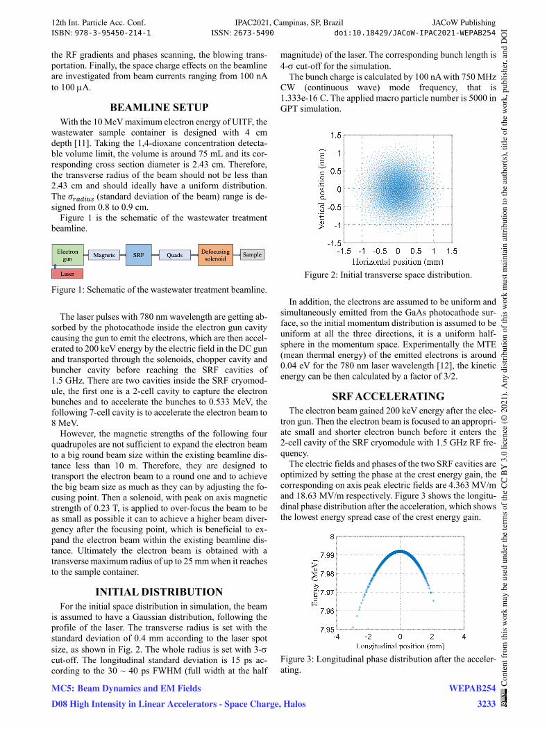
is assumed to have a Gaussian distribution, following the profile of the laser. The transverse radius is set with the standard deviation of 0.4 mm according to the laser spot size, as shown in Fig. 2. The whole radius is set with 3- cut-off. The longitudinal standard deviation is 15 ps ac-cording to the 30 ~ 40 ps FWHM (full width at the half
magnitude) of the laser. The corresponding bunch length is 4- cut-off for the simulation.
The bunch charge is calculated by 100 nA with 750 MHz CW (continuous wave) mode frequency, that is 1.333e-16 C. The applied macro particle number is 5000 in GPT simulation.
Figure 2: Initial transverse space distribution.
In addition, the electrons are assumed to be uniform and simultaneously emitted from the GaAs photocathode sur-face, so the initial momentum distribution is assumed to be uniform at all the three directions, it is a uniform half-sphere in the momentum space. Experimentally the MTE (mean thermal energy) of the emitted electrons is around 0.04 eV for the 780 nm laser wavelength [12], the kinetic energy can be then calculated by a factor of 3/2.
SRF ACCELERATING The electron beam gained 200 keV energy after the elec-
tron gun. Then the electron beam is focused to an appropri-ate small and shorter electron bunch before it enters the 2-cell cavity of the SRF cryomodule with 1.5 GHz RF fre-quency.
The electric fields and phases of the two SRF cavities are optimized by setting the phase at the crest energy gain, the corresponding on axis peak electric fields are 4.363 MV/m and 18.63 MV/m respectively. Figure 3 shows the longitu-dinal phase distribution after the acceleration, which shows the lowest energy spread case of the crest energy gain.
Figure 3: Longitudinal phase distribution after the acceler-ating.
12th Int. Particle Acc. Conf. IPAC2021, Campinas, SP, Brazil JACoW PublishingISBN: 978-3-95450-214-1 ISSN: 2673-5490 doi:10.18429/JACoW-IPAC2021-WEPAB254
MC5: Beam Dynamics and EM Fields
D08 High Intensity in Linear Accelerators - Space Charge, Halos
WEPAB254
3233
Con
tent
from
this
wor
km
aybe
used
unde
rthe
term
sof
the
CC
BY
3.0
licen
ce(©
2021
).A
nydi
stri
butio
nof
this
wor
km
ustm
aint
ain
attr
ibut
ion
toth
eau
thor
(s),
title
ofth
ew
ork,
publ
ishe
r,an
dD
OI
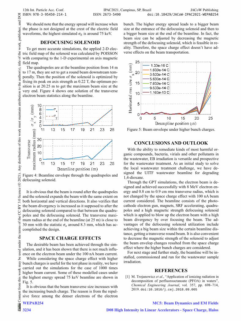
We should note that the energy spread will increase when the phase is not designed at the crest of the electric field waveforms, the highest simulated 𝜎 is around 75 keV.
DEFOCUSING SOLENOID To get more accurate simulations, the applied 2-D elec-
tric field map of the solenoid was calculated by POISSON with comparing to the 1-D experimental on axis magnetic field map.
The quadrupoles are at the beamline position from 14 m to 17 m, they are set to get a round beam downstream tem-porally. Then the position of the solenoid is optimized by fixing its peak on axis strength as 0.22 T, the optimum po-sition is at 20.25 m to get the maximum beam size at the very end. Figure 4 shows one solution of the transverse electron beam statistics along the beamline.
Figure 4: Beamline envelope through the quadrupoles and defocusing solenoid.
It is obvious that the beam is round after the quadrupoles and the solenoid expands the beam with the same extent on both horizontal and vertical directions. It also verifies that the beam divergency is increased as it supposed to after the defocusing solenoid compared to that between the quadru-poles and the defocusing solenoid. The transverse maxi-mum radius at the end of the beamline (at 25 m) is close to 30 mm with the statistic 𝜎 around 8.3 mm, which has ac-complished the design.
SPACE CHARGE EFFECTS The desirable beam has been achieved through the sim-
ulation, and it has been shown that there is not much influ-ence on the electron beam under the 100 nA beam current.
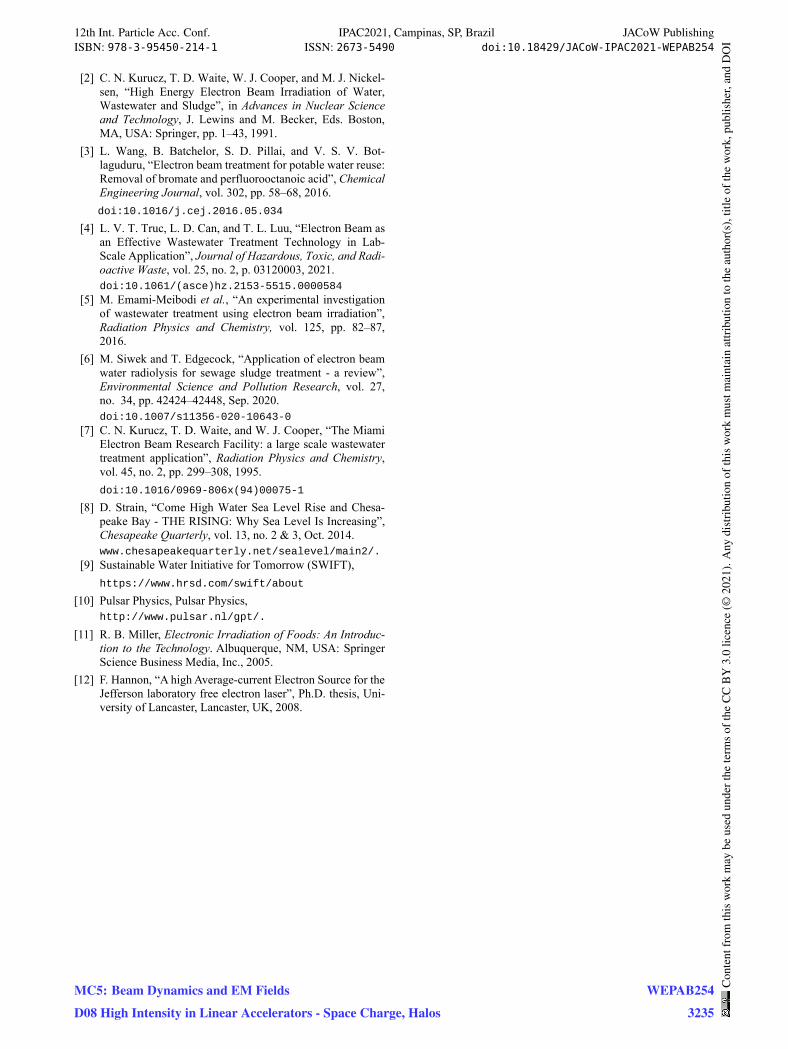
While considering the space charge effect with higher bunch charges is useful for the test phase in reality, we have carried out the simulations for the case of 1000 times higher beam current. Some of these modelled cases under the highest energy spread 75 keV beamline are shown in Fig. 5.
It is obvious that the beam transverse size increases with the increasing bunch charge. The reason is from the repul-sive force among the denser electrons of the electron
bunch. The higher energy spread leads to a bigger beam size at the entrance of the defocusing solenoid and then to a bigger beam size at the end of the beamline. In fact, the beam size can be adjusted by decreasing the magnetic strength of the defocusing solenoid, which is feasible in re-ality. Therefore, the space charge effect doesn’t have ad-verse effects on the beam transportation.
Figure 5: Beam envelope under higher bunch charges.
CONCLUSIONS AND OUTLOOK With the ability to remediate kinds of most harmful or-
ganic compounds, bacteria, virials and other pollutants in the wastewater, EB irradiation is versatile and prospective for the wastewater treatment. As an initial study to solve the local wastewater treatment challenge, we have de-signed the UITF wastewater beamline for degrading 1,4-dioxane.
Through the GPT simulations, the electron beam is de-signed and achieved successfully with 8 MeV electron en-ergy and 0.8 cm to 0.9 cm rms transverse radius, which is not changed by the space charge effect with 100 nA beam current considered. The beamline consists of the photo-cathode electron gun, magnets, SRF accelerating, quadru-poles and a high magnetic strength defocusing solenoid which is applied to blow up the electron beam with a high beam divergency by over focusing the beam. The ad-vantages of the defocusing solenoid utilization include achieving a big beam size within the certain beamline dis-tance, getting a transverse round beam. It is also convenient to decrease the magnetic strength of the solenoid to adjust the beam envelop changes resulted from the space charge effect where the higher bunch charges are considered.
For next stage and further study, the beamline will be in-stalled, commissioned and run for the wastewater sample irradiation.
REFERENCES [1] M. Trojanowicz et al., “Application of ionizing radiation in
decomposition of perfluorooctanoate (PFOA) in waters”, Chemical Engineering Journal, vol. 357, pp. 698–714, 2019. doi:10.1016/j.cej.2018.09.065
x/y (m
m)
Tran
sver
sem
axim
um ra
dius
(mm
)
12th Int. Particle Acc. Conf. IPAC2021, Campinas, SP, Brazil JACoW PublishingISBN: 978-3-95450-214-1 ISSN: 2673-5490 doi:10.18429/JACoW-IPAC2021-WEPAB254
WEPAB254Con
tent
from
this
wor
km
aybe
used
unde
rthe
term
sof
the
CC
BY
3.0
licen
ce(©
2021
).A
nydi
stri
butio
nof
this
wor
km
ustm
aint
ain
attr
ibut
ion
toth
eau
thor
(s),
title
ofth
ew
ork,
publ
ishe
r,an
dD
OI
3234
MC5: Beam Dynamics and EM Fields
D08 High Intensity in Linear Accelerators - Space Charge, Halos
[2] C. N. Kurucz, T. D. Waite, W. J. Cooper, and M. J. Nickel-sen, “High Energy Electron Beam Irradiation of Water, Wastewater and Sludge”, in Advances in Nuclear Science and Technology, J. Lewins and M. Becker, Eds. Boston, MA, USA: Springer, pp. 1–43, 1991.
[3] L. Wang, B. Batchelor, S. D. Pillai, and V. S. V. Bot-laguduru, “Electron beam treatment for potable water reuse: Removal of bromate and perfluorooctanoic acid”, Chemical Engineering Journal, vol. 302, pp. 58–68, 2016. doi:10.1016/j.cej.2016.05.034
[4] L. V. T. Truc, L. D. Can, and T. L. Luu, “Electron Beam as an Effective Wastewater Treatment Technology in Lab-Scale Application”, Journal of Hazardous, Toxic, and Radi-oactive Waste, vol. 25, no. 2, p. 03120003, 2021. doi:10.1061/(asce)hz.2153-5515.0000584
[5] M. Emami-Meibodi et al., “An experimental investigation of wastewater treatment using electron beam irradiation”, Radiation Physics and Chemistry, vol. 125, pp. 82–87, 2016.
[6] M. Siwek and T. Edgecock, “Application of electron beam water radiolysis for sewage sludge treatment - a review”, Environmental Science and Pollution Research, vol. 27, no. 34, pp. 42424–42448, Sep. 2020. doi:10.1007/s11356-020-10643-0
[7] C. N. Kurucz, T. D. Waite, and W. J. Cooper, “The Miami Electron Beam Research Facility: a large scale wastewater treatment application”, Radiation Physics and Chemistry, vol. 45, no. 2, pp. 299–308, 1995. doi:10.1016/0969-806x(94)00075-1
[8] D. Strain, “Come High Water Sea Level Rise and Chesa-peake Bay - THE RISING: Why Sea Level Is Increasing”, Chesapeake Quarterly, vol. 13, no. 2 & 3, Oct. 2014. www.chesapeakequarterly.net/sealevel/main2/.
[9] Sustainable Water Initiative for Tomorrow (SWIFT), https://www.hrsd.com/swift/about
[10] Pulsar Physics, Pulsar Physics, http://www.pulsar.nl/gpt/.
[11] R. B. Miller, Electronic Irradiation of Foods: An Introduc-tion to the Technology. Albuquerque, NM, USA: Springer Science Business Media, Inc., 2005.
[12] F. Hannon, “A high Average-current Electron Source for the Jefferson laboratory free electron laser”, Ph.D. thesis, Uni-versity of Lancaster, Lancaster, UK, 2008.
12th Int. Particle Acc. Conf. IPAC2021, Campinas, SP, Brazil JACoW PublishingISBN: 978-3-95450-214-1 ISSN: 2673-5490 doi:10.18429/JACoW-IPAC2021-WEPAB254
MC5: Beam Dynamics and EM Fields
D08 High Intensity in Linear Accelerators - Space Charge, Halos
WEPAB254
3235
Con
tent
from
this
wor
km
aybe
used
unde
rthe
term
sof
the
CC
BY
3.0
licen
ce(©
2021
).A
nydi
stri
butio
nof
this
wor
km
ustm
aint
ain
attr
ibut
ion
toth
eau
thor
(s),
title
ofth
ew
ork,
publ
ishe
r,an
dD
OI