design modification of electric vehicleshodhganga.inflibnet.ac.in/bitstream/10603/30743/12... ·...
TRANSCRIPT

CHAPTER- 6
DESIGN &
MODIFICATION OF ELECTRIC
VEHICLE
155
DESIGN & MODIFICATION OF ELECTRIC VEHICLE
6.1 Introduction
Besides having so many features the electric vehicles are not a very
common name especially in India market. The basic reason why the
customers are reluctant to buy the electric vehicle is its efficiency. Such
vehicles are not suitable for long journey, as it is required to recharge after
covering certain distance. Whereas with gasoline based vehicle one time
fill will last for a long distance depending upon the mileage of the vehicle.
Also the fuelling does not take long time but to charge a electric vehicle it
takes 6-8 hrs.
Increasing its efficiency can only increase the popularity of the electric
vehicle. If the vehicle will run for a long distance after one time charge,
people will surely come up to buy the vehicle.
The very basic idea by which efficiency can be improved is by charging the
battery of the vehicle during running condition. Now the question arises
how a battery can be charged when the vehicle is running since it needs
continuous A.C current supply to get charged. Well the simple answer to
this question is a decades old theory ALTERNATOR.
ALTERNATOR is a device similar to the generator its basic function is to
generate electricity Some theory below will clear the concept of electricity
generation through alternator
6.2 Electricity And Magnets
When you put electncity (current) down a wire, the wire will have a
magnetic field around it. Conversely, if you move a wire through a
magnetic field, a small current (electricity) is created in the wire. The more
wires you use and the greater the strength of the magnetic field, the
greater the effect becomes. These two inverse principles are the basis for
electric motors, generators, alternators, and even things like the solenoid
inside of a relay. If you have one item (movement or electricity), you can
convert it into the other. Also tied in here is the fact that magnets repel and
attract each other- that's pat of how you make an electric motor move. You
can use more turns of wire (windings) to generate a stronger effect.
What about voltage vs. current? Well, current is a measure of how much
stuff is flowing down a wire - kind of like the number of gallons of water that
are flowing down a pipe every second. Voltage is a measure of pressure -
like how many pounds per square inch (PSI) of air are in your tires. They
measure different things, but they can be confusing since you can't "see"
electricity.
What about AC vs. DC? These stand for Alternating Current and Direct
Current. AC is the stuff used in your house. DC is the stuff used in your car
and what you get out a battery. The difference is that in DC current always
flows in the same direction - from positive to negative (or, if you're a real
phys1cs geek. from negative to positive) - while AC alternates the flow of
current between the two d1rect1ons at some rate. This rate is expressed as

157
cycles per second, or Hz (pronounced "hurtz"). In the USA, the electricity in
your house is changing directions at 60Hz- 60 times a second.
The final tid-bit of information is that when you spin wires and magnets
near each other, you create AC in the wire. This is because the wire and
magnets are continuously moving closer to and farther away from each
other in a repeated cycle. As they move closer together, the current moves
one way. As they are farther apart, the current goes the other way. If
you've ever seen the typical "sine wave" graph of AC power, that exactly
what I'm talking about here. This is important because you need some way
to make that AC into DC to use it in your car. The process of charging AC
into DC is called rectification. How you choose to do that is the key design
difference between an alternator and a generator.
6.3 Alternator
The more modern and more capable alternator is explained here. Every
modern vehicle uses an alternator - and for good reasons. It is more
complicated than a generator, but that added complexity brings a few very
good features that you will most certainly want on your vehicle - mainly the
fact that it will charge the battery at idle and can support the higher
amperages needed to run all of the electrical equipment on a modern
vehicle Alternators tend to be more reliable than a generator and have
fewer "hard to diagnose" problems as the system ages - particularly the
1nternally regulated models The rnternally regulated models are also very
I.' X
easy to service if something goes wrong - there is only one part to fail (the
alternator itself) and replacing it 1s a simple 30 minute job. This all adds up
to the performance and reliability that is expected in a modern vehicle.
The key different between an alternator and a generator is what spins and
what is fixed. On a generator, windings of wire (the armature) spin inside a
fixed magnetic field. On an alternator, a magnetic field is spun inside of
windings of wire called a stator to generate the electricity. This allows the
wires to be directly and easily connected to their outputs without the need
for sliding contacts to carry the relatively high output current. The magnetic
field is still generated via electro magnets mounted on a rotor, and the
relatively small field current that powers them is supplied to the rotor by two
small brushes that each ride on a separate and continuous slip rings.
These smooth slip rings (unlike the comparatively rough contacts on a
commutator in a generator) and the fact that the relatively heavy windings
are fixed instead of rotating allows the alternator to be spun to much higher
speeds. This allows it to reach it's maximum output sooner and to be spun
fast enough at engine idle speeds to produce enough electricity to power
most (if not all) of the needs of the car without relying on the battery.
There are typically three separate windings of wire in the stator that are all
set to so that the AC current that is generated is slightly out of phase in
each one. The peaks and valleys of the rising and falling current do not
happen at the same time. rather they are staggered a bit. This increases
and smoothes the electncal output of the alternator much the same way
/5'1
that a 8 cylinder car runs more smoothly than a 4 cylinder one does - there
are more power pulses happening in each revolution allowing more total
power and better smoothness
The process of rectifying the AC current into DC current is handled inside
the alternator by something more complex than a commutator - diodes. A
diode is a "solid state" device that allows current to flow in one direction
only without any moving parts. It relies on the different electrical properties
of the materials it is made of to act as a one-way valve for current. By
arranging diodes so that current from each of the three stator wires is only
allowed to pass in one direction, and by connecting the three outputs
together, you get a very smooth and stable DC output without any moving
parts. (This arrangement is typically manufactured as a single part and is
referred to as the diode pack or diode trio.) This lack of moving parts
makes the alternator not only very reliable - but also comparatively
inexpensive to build and repair.
Alternators do not need to be polarized after installation. You mount them
to the engine, plug them in, and go. This is an advantage for not only
manufacturing the car but for servicing it as well.
On externally regulated models, there are typically four connections on the
alternator - the large output terminal (BAT), the ground terminal (GRD)
which may be "implied" though the metal mountings of the alternator. the
f1eld connection (F). and terminal #2 on the regulator 1s a separate
connect1on to one of the three poles on the stator (R) Unlike on a
160
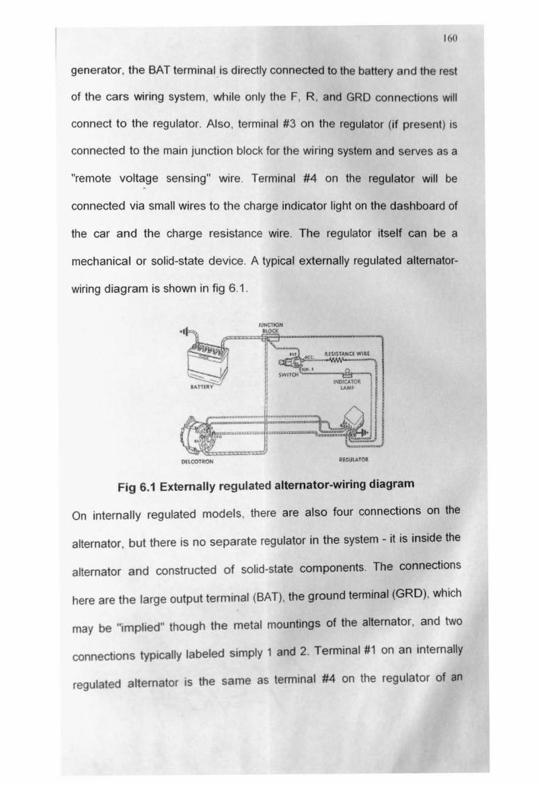
generator, the BAT terminal is directly connected to the battery and the rest
of the cars wiring system, while only the F, R, and GRD connections will
connect to the regulator. Also , terminal #3 on the regulator (if present) is
connected to the main junction block for the wiring system and serves as a
"remote volt~ge sensing" wire. Terminal #4 on the regulator will be
connected via small wires to the charge indicator light on the dashboard of
the car and the charge resistance wire. The regulator itself can be a
mechanical or solid-state device. A typical externally regulated alternator-
wiring diagram is shown in fig 6.1.
OILCOTRON
Fig 6.1 Externally regulated alternator-wiring diagram
On internally regulated models, there are also four connections on the
alternator, but there is no separate regulator in the system - it is inside the
alternator and constructed of solid-state components. The connections
here are the large output terminal (BAT), the ground terminal (GRD), which
may be "implied" though the metal mountings of the alternator, and two
connections typically labeled simply 1 and 2. Terminal #1 on an internally
regulated alternator is the same as terminal #4 on the regulator of an

161
externally regulated system - it connects to a small wire that is goes to the
charge indicator light on the dashboard of the car and the charge
resistance wire. Terminal #2 on an internally regulated alternator matches
terminal #3 on an external regulator - it is connected to the main junction
block for the wiring system and servers as a "remote voltage sensing wire".
If you are comparing to the externally regulated wiring, then you will note
that the F and 2/R wiring connections are done inside the alternator. A
typical internally regulated alternator wiring diagram shown in fig 6.2
-::::----, ... - .......... .. -···1· ll.f 1'1\'S~~
I. ~ I
" lc• '-,._, ---iliS---. i ,,..,,(~101' 1 ""'~ 1
L4:::.::=$.==:::. =~:=:=:JI .. .,.,. "'"~( t•
tJ(~ =~=~·) t"Ch •~r¢11
Fig 6.2 Internally regulated alternator wiring diagram
6.4 Regulator
What exactly does that little black box on your inner fender do? What's the
difference between internally and externally regulated alternators? The
regulator does just what it's name implies - it regulates the output of the
generator or alternator to the proper voltage and current by controlling the
field current that 1s supplied

For all generators and externally regulated alternators, the regulator is a
small device mounted somewhere on the firewall or the inner fender of the
car. It is connected with relatively long wires to the generator or alternator.
It is usually a mechanical device that works by rapidly opening and closing
the contacts of several relays to create the correct "average" voltage and to
limit the current supplied to the correct amount These mechanical
regulators need periodic adjustments and can be somewhat noisy in
operation. They also have moving parts that will fail after a period of time.
Some later-model and aftermarket replacement regulators are solid-state
devices that are quieter and longer lasting even though they look pretty
much the same externally as a mechanical unit.
For internally regulated alternators, the regulator is a solid-state device (no
moving parts) that is mounted inside the alternator casing. These units will
never need replacement separately from the alternator and will last for
many, many years giving trouble-free service. There are no separate wires
to run between the two units, and there are only a few simple connections
to make at the alternator itself.
6.5 Remote Voltage Sensing
Both regulator styles can have what 1s known as a "remote voltage
sens1ng" feature on them - many thanks to the explanations on the MAD
Enterpnses site for finally making this clear enough to me so I could
explain 1t here They have deta1ls on the remote sensing feature, 1-wire vs.
16.1
3-wire alternators, and a great description of a typical muscle car-era
Chevy charging system. The details are interspersed throughout those
documents, but together they provide very valuable insight into how the
typical alternator-based charging system works, and how to modify your
charging system to work correctly using an alternator. All internally
regulated systems come with the remote voltage sensing feature, but not
all externally regulated systems do. Basically, the remote sensing wire
should be connected to the main junction point for the entire electrical
system. This is because the voltage at the place this wire is connected to
will be maintained at the proper level. If this connection is at the alternator
or regulator, then that's where the maximum voltage will be with lower
voltage out in the rest of the electrical system. If you connect this wire to
the main junction point, then the main junction point will have the proper
voltage. The difference that results from this can be very noticeable,
especially in cars with the battery mounted somewhere besides the engine
compartment A 1 V drop is common between the alternator output and the
main junction point in many cars, so if you have 14V at the alternator and
only 13V at the junction point, you may not be doing much better than 12V
by the lime you get to the actual devices that need to use that voltage_ In
th1s theoretical 1V drop scenano, by connecting the remote sensing wire to
the ma1n junction po1nt. you will have 15V at the alternator (yes, 15V - it's
OK and des1red here). 14V at the junction point, and then 13V at the
accessones
164
6.6 Dashboard Indicator Light
If you have an alternator and are using the factory style indicator light on
your dashboard, it is a pretty helpful thing. It helps kick-start the alternator
into working at idle speeds when you first start the car, and it tells you if the
alternator is p~tting out less voltage than the battery has in it, indicating a
problem. The light is connected on one side to the field current system
inside the alternator and to a switched ignition power source on the other
side. When you turn the key on but have not started the car yet, the field
acts as a ground and power flows through the light and out to ground -
lighting the bulb so you know it works. Once you start the car, the voltage
at the field is powered internally by the output of the alternator. If this value
is exactly the same as the battery voltage, then you have the exact same
voltage on each side of the indicator light and they balance each other out -
kind of alike a tug of war in reverse. If all goes well, the light never comes
on, and you drive happily around knowing all is well with your alternator. If
the output of the alternator should drop due to a slipping/broken belt or due
to certain kinds of electrical faults inside the alternator itself, there will be
less voltage on the field side of the light and more voltage on the switched
ignition side of the light. The result is that some amount of electricity will
flow through the light and into the field and the light will glow proportional to
that voltage difference. This is how a slipping belt or an overloaded
alternator will cause the light to glow very dimly, while a full-on failure will
cause the light to glow very bnghtly Note that if you disconnect (or forget

16:\
to connect) the wire at the alternator, the light will never come on and the
alternator may not charge properly.
The dashboard indicator light circuit also typically has an extra wire with a
calibrated resistance in it This wire is run in parallel to the indicator light
and has about a 1 Oohm resistance. It's purpose is to allow slightly more
current to flow to the alternator field current system at initial start-up to
make sure the alternator begins producing power as soon as the engine
starts. About 1 amp total current is flowing to the field current between the
light and the resistance wire, with the resistance wire supplying about 3/4
of an amp. This extra resistance wire does not affect the functionality of the
indicator light in any way.
6. 7 Conversions And Customization
Many "hot rod" style conversions use a modified internally regulated
alternator to eliminate the two small wire connections and only leave the
single large BAT connection to be hooked up. This is usually referred to as
a "one wire" alternator - you only have to run one wire to it instead of the
usual three wires. In this conversion, the dashboard indicator light is
eliminated entirely. the field terminal is connected to the BAT terminal
mternally. and the connection to the other terminal is made inside the
alternator. Conceptually, this conversion works like a factory system
without the indicator light on the dashboard and with the remote voltage
sensing wire connected to the back of the battery. There are several major
drawbacks to this setup One is that you have to to rev the engine up to

166
approx 1100rpm once after the engine is first started for the alternator to
begin charging - the alternator has to reach a high enough RPM so that it
"self-excites". Another is that the field connection inside the alternator can
allow a small current draw while the vehicle is not running, and this can
cause a dead battery if the car is stored for a period of time. Lastly, you do
not have the advantage of the remote voltage-sensing feature and that
means poor electrical system performance - dim headlights, slow wipers,
and various other maladies. There are some great details on this at the
MAD Enterprises website - check out their articles on the remote sensing
feature, 1-wire vs. 3-wire alternators, and a great description of a typical
muscle car-era Chevy charging system for more details.
I personally do not recommend the "one wire" conversions - the dubious
improvement in under hood aesthetics just isn't worth it. Your neighbors will
probably not appreciate you revving your car up to 1100 rpm each morning
at 7am before you head out to work and it makes your otherwise cool ride
annoying to drive. Many "tamer" drivers (like your wife, if she's anything like
mine) will often start the car and drive for some time before making it to
1100 rpm for the first time. During that entire time, she would be draining
the battery if the vehicle was using a "one wire" conversion - and that's not
cool. It is very simple to hook up the extra wire for the indicator light and it
makes the car much more pleasant to drive - you have one less thing to
worry about when you just want to get in the car and go. In addition. many
of the vehicles that use the 1-w1re conversion tend to be spec1alty use

167
vehicles and thus do get stored for a long time between uses, so the
battery drain could be an issue. If you do go that route, consider a battery
disconnects or some form of "battery maintainer" to keep your battery
charged between vehicle uses. Lastly, the problems with reduced voltage
as a result of not having the remote voltage-sensing feature can be a very
big deaL
If you are still pondering a "one-wire" conversion, it should be noted that
you could partially eliminate the second wire by using a short pigtail to
hook it directly to the BAT connection on the alternator. If you examine the
diagram above for an internally regulated alternator, you will see that this
wire eventually ties back into the wire that is attached to the BAT terminal
anyway. A final word of caution is to think twice (and then think about it
again) before deviating frorn the way the factory did things if you want to
customize your charging system. Modern factory charging systems are
amazing reliable and trouble-free. There is a reason the factory did what
they did. Adding those extra lengths of wire probably costs them about $1
a car - and although that may not sound like much, when you make a
million cars. $1 per car is a $1,000,000 less in potential profits. That's some
serious money - and that's just for a few pieces of wire. (This detail is why
the factory goes crazy trying to save every penny possible when building
the car - rt really adds up fast and they like making all the money they can.)
Also. when you make a mrllion cars and find out something is wrong with
them (frre hazard. doesn't always charge the battery, etc.) it ends up being
16X
very expensive - both in real dollars and from a public-relations perspective
-to repair the problem. Melding two factory-style systems to upgrade your
vehicle to newer standards is a worthy goal and often a very easy thrng to
do - just be sure you get all the details right so you can enjoy your vehicle
for many trouble-free miles to come. Take the time to make sure each wire
you put into the car or change the function (aka, push more current through
it) is up to the task you are placing before it.
6.8 History
In recent trend reducing pollution is an important task. In metro cities where
large number of vehicle are on road creates heavy pollution. To overcome
these, different steps are being taken. One of the steps is use of electrically
driven vehicle. It produces very less amount of exhaust emission and
produce less amount of pollution. But there is a draw back of electrically
driven vehicle. It runs for shorter period and can travel shorter distance.
Again recharging to be done and have to wait for certain time for charging,
charging is possible through 15 amp socket. This facility is available at
different charging station. There may be alternate arrangement are to be
made for switching over to Petrol/ Diesel for recharging the vehicle in case
of emergency. The drawback of short duration running is great
disadvantage of electnc vehicle. A new approach is being made to
1ncrease the duration running period by recharging the Battery with some
add1t1onal device f1tment 1n the vehicle without power loss and without
losing any engine efficiency. The rechargeable facility will be in-built to the
vehicle. No connection to be taken from Engine shaft for running the
dynamo for charging the battery.
6.9 Design Aspects
The vehicle, which is presently running with electric power, is REVA, which
is produced by REVA Pvt. Organization, Bangalore and marketing slowly to
the other states. Due to short duration running the market is not responding
highly. Customer does not satisfy the running aspects. Now little
modification are being suggested to increase the duration by recharging
the battery with the help of Dynamo fitted in the vehicle by belt running
along with the shaft. There is a Fan to be fitted in front of vehicle (not
protruding outside) through forward motion with are resistance a heavy
amount of wind is being sucked and passes through the Fan blade and try
to rotate with high RPM. When RPM increased connect the Fan belt to the
dynamic with suitable arrangement shown in fig. Dynamo starts charging
the battery with the help electrical circuit. The battery will be getting
charged. During higher speed of vehicle charging process will continue.
When applying breaks lowers the speed the charging of battery is to be
discontinued by puttmg a Relay/ Cutout along with sensor of speed. When
the speed lowered at 1 000 RPM the relay will disconnect the charging
process further the system will maintain normal running condition. But
when the speed mcreases more than 1000 RPM the relay will energize the
170
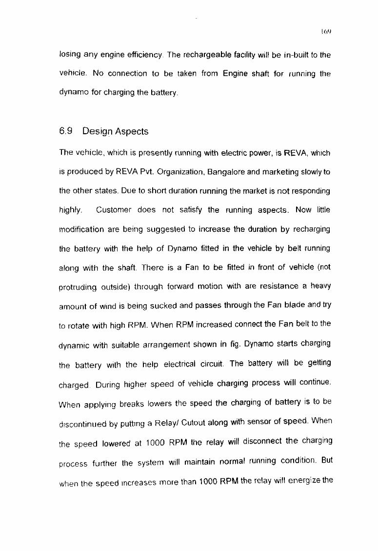
electrical circuit the charging continues. This process can continue for a
long period of running the engine & increasing engine efficiency. Two-block
diagram shows the complete design process along with engine running
condition with different speeds.
Switch Electrical Motor
48 V Battery
Fig. - 6.3 Wiring diagram of normal condition in Electric vehicle
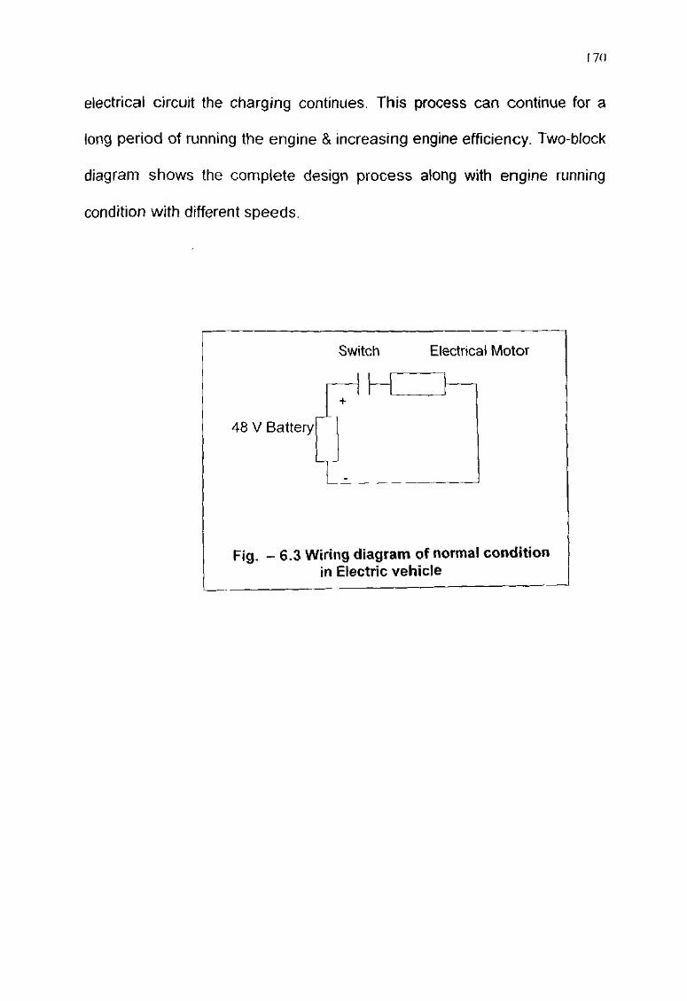
Switch Electrical Motor
"" ..--------c~-/1-/'·_ •. =r-
48 V Battery -]
Relay (Cut out) 1-L__f-----2)..-Fan Belt
Dynamo
Fig 6.4 Modified Wiring Diagram of Electric Vehicle
6.10 Accessories Of Modified Design
Cut Out/ Relay Sensor: -
171
Sensing Relay to be used which sense the speed/RPM. At increased RPM
it energized the circuit allow the current to go to Battery. At decrease RPM
it de-energize the circuit.
Battery: -
48V. 200amp/hr EV tubules lead acid battery, which is used to rely the
vehicle with the help of electronic starter, charge times 2.5 hours up to 80%
and 100% in 6 hours and range is 90km per charge. Top speed can be
mamtained 50 kml hr & range is 95 kmlcharge
17~
Dynamo:-
When dynamo is running current cannot flow through the shunt winding. It
produces a magnetic flow that overcomes the spring tension so causing
the contacts to close and can passes the current to charge the 48V battery.
Motor:-
It is having high torque (70Nm) separately excited DC motors 13kw peak
power capacity. 400 Amp. microprocessor based with regenerative
braking, 220V-2.2kw high frequency switch mode type charger. EMS is
microprocessor based battery management system.
Fan:-
Cooling Fan, which can rotate with forward Air resistance free to rotate with
high RPM without any friction losses.
Belt Pulley: -
Belt Pulley connected with fan shaft to rotate the Dynamo shaft to produce
electricity and can charge the 48V battery to increases the power direction.
Clutch shaft: -
Wh1ch is used to connect the belt shaft along with Fan shaft with increased
RPM. At lower RPM it should disconnect the belt shaft from Fan shaft Fig.-
3 shown the arrangement of shaft assembly to connect fan shaft.

IT\
Battery I I Fan Shall -L _Q C'ut Out -- 0 Fan
I I Clutch Shaft
-0---- ---
Dynamo Shaft
Fig.-6.5: Wiring Diagram of Shaft Assembly
6.11 Safety Aspects
Safety:
The specially designed Steel space frame and side impact beam cocoons
passengers in the event of a collision, shielding them from an impact. The
body of the Reva is made of high impact ABS (Acrylonitrile Butadiene
Styrene) that is dent resistant and non-corrosive.
This ensures minimum damage to the car and enhances protection to
passengers in the event of a collision. Hit the Reva's ABC body with a
hammer and it will not dent. Unlike steel, ABS bounces back into shape.
Eco-friendly:
Being an Electric Vehicle. Reva is zero polluting and noiseless. It does not
require frequent oil changes. Moreover Reva has high recyclable content.
High on Technology
174
Two computers and the state-of-the-art electronics in the Reva provide an
efficient energy management system with advanced computerized vehicle
diagnostics.
The regenerative braking in the Reva recovers useful electricity by putting
it back into the batteries. Regenerative braking lets the motor act as a
generator, converting the vehicle's momentum into electricity.
Prime Mover:
The prime mover in REVA, is the motor. It is similar to the engine in a
conventional car. Reva has a 13 kW separately excited DC motor with a
high torque of 70 kW separately excited DC motor with a high torque of 70
Nm at zero speed. When in use, the motor converts the energy stored in
the Power Pack into mechanical motion. The high torque electric motor
ensures a quick acceleration. The power from the motor is delivered to the
wheels through the Trans-axle that propels the vehicle. While braking, the
motor acts like a generator and recharges the Power Pack.
Power Pack:
Power Pack consists of e1ght 6-Volt EV tubular type lead acid batteries that
attain 80% state of charge in under 2.5 hours. A complete charge is
achieved in less than s1x hours. The Power Pack is housed beneath the
front seats. which lowers the center of gravity, thus increasing the safety of
passengers. Charging REVA is a safe and easy process- Just plug into a
220 Volt. 15 Ampere socket - at home or at work.

175
Charger:
It converts AC into DC power to charge the power pack. The charger is
computer controlled with an in-built stabilizer and auto shut-off mechanism.
The smart charger's output is connected to the power pack and ensures
that optimum current and voltage is maintained at all times.
Computerized Motor Controller:
This regulates the flow of energy from the Power pack to the Motor in direct
relation to pressure applied on the accelerator. It ensures perfect speed
control and optimum use of energy in both forward and reverse directions.
The brain of REVA is the Energy Management system.
Energy Management System:-
It monitors and controls all vital functions. The EMS is a computer based
system that optimizes charging and energy output of batteries to maximize
operating range and improve performance. The system also predicts
available range for a given state of battery charge and is a standard feature
on the Reva.
The EMS also maintains an electronic log of the vehicle performance,
enables service personnel to run diagnostic checks on the car to give
service information about the car.

176
6.12 Result and Discussion
To obtain zero pollution or to reduce the pollution this type of electrically
driven cars are most suitable in the market or in metro cities. To increase
the duration suitable suggestion are being with the help of additional device
fitment. By this additional fitment cost will increase about 5% of total cost.
But the increased power-duration and increased length of period of running
will be 30% increased with the engine efficiency. Hence these systems are
most suitable to save the earth for global warning.