design manual m 22-01 may 2003 · ... rock, and surfacing materials november 1999 ... contents...
TRANSCRIPT
Page 1 of 2
Design Manual Revision Summaries Design Policy and Standards Revisions
May 2003 Revision The revision starts after page 2 of this document
The Design Office is launching a new service of providing a summary of the most recent revisions to the Design Manual.
Design Manual Reminder: Revision marks are used throughout to highlight content changes. This is primarily demonstrated through the use of sidebars and underlining. Manual users should periodically check the Design Manual Errata webpage located on the Design Policy page under “What’s New”. Manual users should report all undocumented errors to ensure all errors are documented. General
• Review and update references, definitions, titles, & acronyms as appropriate. • Clean up references to metric units of measure • The “Documentation” subheadings are revised to direct the reader to the
Documentation Check List on line. Design Manual Supplements In alignment with the major Design Manual revision packages, an occasional Design Manual supplement may be issued. There have been three issued since May 2003. They are listed with the chapters that are affected. Chapter 430 DM Supplement “Urban Roadways”, dated 7/22/2003 Chapter 440 DM Supplement “Urban Roadways”, dated 7/22/2003 Chapter 640 DM Supplement “Urban Roadways”, dated 7/22/2003 Chapter 700 Roadside Safety – (May 2003)
This chapter was rewritten to: • Incorporate the Design Manual Supplement - Design Clear Zone • Provided clarification on responsibilities for establishing design clear zone –
differentiating between managed and limited access, within and outside of incorporated cities and towns
• Consideration for removal of fixed objects even though outside R.O.W. • Expanded list of fixed objects that may require mitigation

Page 2 of 2
• Added policy for use Shoulder Rumble Strips on undivided highways
Chapter 1050 High Occupancy Vehicle Facilities – (May 2003)
This chapter was completely rewritten to: • Revise and clarify terminology and references • Revise guidance on hours of operation • Remove guidance on Direct Access Ramps, directing the reader to use the HOV
Direct Access Design Guide • Rather than being recommended, Direct Access HOV connections may now be
considered for an inside HOV lane • Pros and cons of 24 hour a day HOV operation noted • Add guidance on Barrier Separated/Separated Roadway HOV facilities • Present design criteria for Arterial Street HOV lanes • Revise the design of 2-lane ramp meter with bypass • Revise figures depicting ramp configurations and flyovers
Chapter 1130 Retaining Walls and Steep Reinforced Slopes – (May 2003)
Minor revisions to this chapter included: • Clarification on documentation required for sole source proprietary wall
Chapter 1140 Noise Barriers – (May 2003)
Minor revisions to this chapter included: • Additional considerations for the designing and locating a noise barriers • Added guidance on fall protection • Added reference to the Roadside Manual for guidance on vegetation on berms and
redirectional land forms STANDARD PLAN REVISIONS APRIL 7, 2003 46 new or revised standard plans Significant additions
• Dowel bar retrofit details for rehabilitating cement concrete pavement • Details for repairing cement concrete pavement • Thrie-beam guardrail bull-nose for median installations • Cement concrete curb designs conforming with AASHTO “Green Book” • ADA-compliant sidewalk ramps with detectable warning strips • ADA-compliant concrete driveway entrances • New shoulder rumble strip plans for undivided highways • New MUTCD-compliant work zone traffic control plans for local agencies

Page 1 of 1
Publications Transmittal
Transmittal Number Date PT 03-034
May 2003
Publication Distribution To: All English Design Manual holders Publication Title Publication Number Design Manual (English) Revision 2002-2 M 22-01 Originating Organization Environmental and Engineering Service Center, Design Office, Design Policy,
Standards, and Safety Research Unit through Engineering Publications
Remarks and Instructions
Remarks:
Additional copies may be purchased from: Washington State Department of Transportation Finance and Administration Directional Documents and Engineering Publications PO BOX 47408 Olympia, WA 98504-7408
Phone: (360) 705-7430 Fax: (360) 705-6861 E-mail: [email protected]
Instructions: Page numbers and corresponding sheet-counts are given in the table below to indicate portions of the Design Manual that are to be removed and inserted to accomplish this revision.
Remove Insert Chapter Pages Sheets Pages Sheets
Letter’s List N/A 1 N/A 1 Contents 1 – 24 12 1 – 24 12 700, “Roadside Safety” 1 – 16 8 1 – 17 9 1050, “High Occupancy Vehicles” 1 – 36 18 1 – 16 8 1130, “Retaining Walls and Steep Slopes” 1 – 30 15 1 – 30 15 1140, “Noise Barriers” 1 – 4 2 1 – 4 2 Index 1 – 18 9 1 – 18 9
Distributed By Phone Number Signature Directional Documents and Engineering Publications
(360) 705-7430 FAX: 705-6861

Letters List May 12, 2003
Design Manual Contents May 2003 Amendments
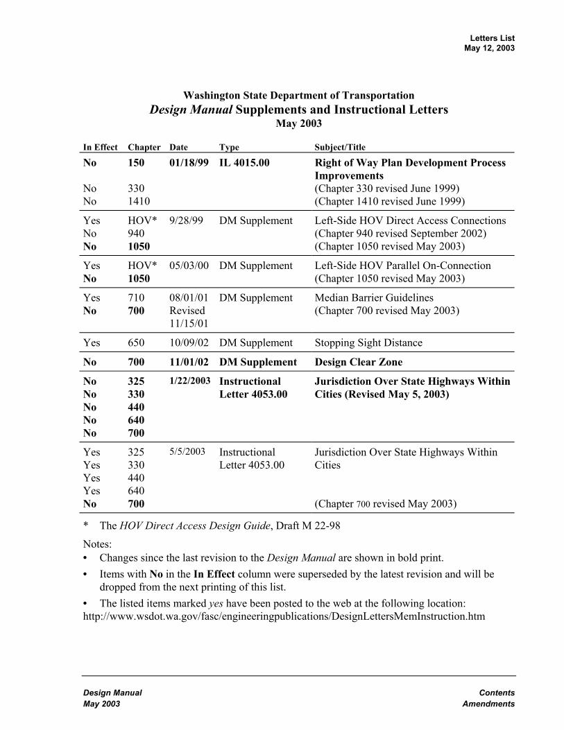
Washington State Department of Transportation Design Manual Supplements and Instructional Letters
May 2003
In Effect Chapter Date Type Subject/Title
No No No
150 330 1410
01/18/99 IL 4015.00 Right of Way Plan Development Process Improvements (Chapter 330 revised June 1999) (Chapter 1410 revised June 1999)
Yes No No
HOV* 940 1050
9/28/99 DM Supplement Left-Side HOV Direct Access Connections (Chapter 940 revised September 2002) (Chapter 1050 revised May 2003)
Yes No
HOV*1050
05/03/00 DM Supplement Left-Side HOV Parallel On-Connection (Chapter 1050 revised May 2003)
Yes No
710 700
08/01/01 Revised 11/15/01
DM Supplement Median Barrier Guidelines (Chapter 700 revised May 2003)
Yes 650 10/09/02 DM Supplement Stopping Sight Distance
No 700 11/01/02 DM Supplement Design Clear Zone
No No No No No
325 330 440 640 700
1/22/2003 Instructional Letter 4053.00
Jurisdiction Over State Highways Within Cities (Revised May 5, 2003)
Yes Yes Yes Yes No
325 330 440 640 700
5/5/2003 Instructional Letter 4053.00
Jurisdiction Over State Highways Within Cities (Chapter 700 revised May 2003)
* The HOV Direct Access Design Guide, Draft M 22-98
Notes: • Changes since the last revision to the Design Manual are shown in bold print. • Items with No in the In Effect column were superseded by the latest revision and will be
dropped from the next printing of this list. • The listed items marked yes have been posted to the web at the following location: http://www.wsdot.wa.gov/fasc/engineeringpublications/DesignLettersMemInstruction.htm


Design Manual ContentsMay 2003 Page 1
ContentsDate
Division 1 General InformationChapter 120 Planning May 2000
120.01 General120.02 References120.03 Definitions120.04 Legislation and Policy Development120.05 Planning at WSDOT120.06 Linking Transportation Plans120.07 Linking WSDOT Planning to Programming
Chapter 140 Managing Project Delivery September 2002140.01 General140.02 References140.03 Definitions140.04 Resources140.05 Process and Tools140.06 Responsibilities140.07 Documentation
Division 2 Hearings, Environmental, and PermitsChapter 210 Public Involvement and Hearings December 1998
210.01 General210.02 References210.03 Definitions210.04 Public Involvement210.05 Hearings210.06 Environmental Hearing210.07 Corridor Hearing210.08 Design Hearing210.09 Access Hearing210.10 Combined Hearings210.11 Administrative Appeal Hearing210.12 Documentation
Chapter 220 Project Environmental Documentation June 1989220.01 General220.02 Definitions220.03 Project Classification220.04 Class I, EIS220.05 Class II, CE220.06 Class III, EA/Checklist220.07 Project Reevaluation220.08 Project Reviews
Contents Design ManualPage 2 May 2003
Date
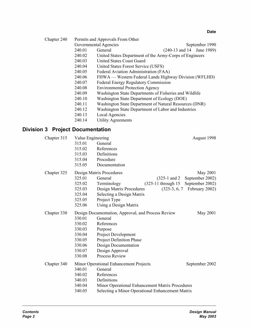
Chapter 240 Permits and Approvals From OtherGovernmental Agencies September 1990240.01 General (240-13 and 14 June 1989)240.02 United States Department of the Army-Corps of Engineers240.03 United States Coast Guard240.04 United States Forest Service (USFS)240.05 Federal Aviation Administration (FAA)240.06 FHWA — Western Federal Lands Highway Division (WFLHD)240.07 Federal Energy Regulatory Commission240.08 Environmental Protection Agency240.09 Washington State Departments of Fisheries and Wildlife240.10 Washington State Department of Ecology (DOE)240.11 Washington State Department of Natural Resources (DNR)240.12 Washington State Department of Labor and Industries240.13 Local Agencies240.14 Utility Agreements
Division 3 Project DocumentationChapter 315 Value Engineering August 1998
315.01 General315.02 References315.03 Definitions315.04 Procedure315.05 Documentation
Chapter 325 Design Matrix Procedures May 2001325.01 General (325-1 and 2 September 2002)325.02 Terminology (325-11 through 15 September 2002)325.03 Design Matrix Procedures (325-3, 6, 7 February 2002)325.04 Selecting a Design Matrix325.05 Project Type325.06 Using a Design Matrix
Chapter 330 Design Documentation, Approval, and Process Review May 2001330.01 General330.02 References330.03 Purpose330.04 Project Development330.05 Project Definition Phase330.06 Design Documentation330.07 Design Approval330.08 Process Review
Chapter 340 Minor Operational Enhancement Projects September 2002340.01 General340.02 References340.03 Definitions340.04 Minor Operational Enhancement Matrix Procedures340.05 Selecting a Minor Operational Enhancement Matrix

Design Manual ContentsMay 2003 Page 3
Date340.06 Project Type340.07 Using a Minor Operational Enhancement Matrix340.08 Project Approval340.09 Documentation
Division 4 Project Design CriteriaChapter 410 Basic Design Level May 2001
410.01 General (410-2 February 2002)410.02 Required Basic Safety Items of Work410.03 Minor Safety and Minor Preservation Work
Chapter 430 Modified Design Level May 2001430.01 General (430-10 February 2002)430.02 Design Speed430.03 Roadway Widths430.04 Ramp Lane Widths430.05 Stopping Sight Distance430.06 Profile Grades430.07 Cross Slope430.08 Fill Slopes and Ditch Inslopes430.09 Intersections430.10 Bridges430.11 Documentation
Chapter 440 Full Design Level May 2001440.01 General440.02 References440.03 Definitions440.04 Functional Classification440.05 Terrain Classification440.06 Geometric Design Data440.07 Design Speed440.08 Traffic Lanes440.09 Shoulders440.10 Medians440.11 Curbs440.12 Parking440.13 Pavement Type440.14 Structure Width440.15 Grades
Division 5 Soils and PavingChapter 510 Investigation of Soils, Rock, and Surfacing Materials November 1999
510.01 General510.02 References510.03 Materials Sources510.04 Geotechnical Investigation, Design, and Reporting510.05 Use of Geotechnical Consultants

Contents Design ManualPage 4 May 2003
Date510.06 Geotechnical Work by Others510.07 Surfacing Report510.08 Documentation
Chapter 520 Design of Pavement Structure February 2002520.01 Introduction (520-7 through 14 April 1998)520.02 Estimating Tables
Chapter 530 Geosynthetics April 1998530.01 General (530-13 November 1999)530.02 References530.03 Geosynthetic Types and Characteristics530.04 Geosynthetic Function Definitions and Applications530.05 Design Approach for Geosynthetics530.06 Design Responsibility530.07 Documentation
Division 6 GeometricsChapter 610 Highway Capacity June 1989
610.01 General610.02 Definitions and Symbols610.03 Design
Chapter 620 Geometric Plan Elements April 1998620.01 General (620-1 May 2001)620.02 References (620-4 November 1999)620.03 Definitions620.04 Horizontal Alignment620.05 Distribution Facilities620.06 Number of Lanes and Arrangement620.07 Pavement Transitions620.08 Procedures620.09 Documentation
Chapter 630 Geometric Profile Elements April 1998630.01 General (630-2 May 2001)630.02 References630.03 Vertical Alignment630.04 Coordination of Vertical and Horizontal Alignments630.05 Airport Clearance630.06 Railroad Crossings630.07 Procedures630.08 Documentation
Chapter 640 Geometric Cross Section February 2002640.01 General640.02 References640.03 Definitions640.04 Roadways640.05 Superelevation640.06 Medians and Outer Separations

Design Manual ContentsMay 2003 Page 5
Date640.07 Roadsides640.08 Roadway Sections640.09 Documentation
Chapter 650 Sight Distance April 1998650.01 General (650-3 June 1999)650.02 References (650-4 November 1999)650.03 Definitions (650-8 May 2000)650.04 Passing Sight Distance (650-9 May 2001)650.05 Stopping Sight Distance650.06 Decision Sight Distance
Division 7 Roadside Safety ElementsChapter 700 Roadside Safety May 2003
700.01 General700.02 References700.03 Definitions700.04 Clear Zone700.05 Hazards to be Considered for Mitigation700.06 Median Considerations700.07 Other Roadside Safety Features700.08 Documentation
Chapter 710 Traffic Barriers May 2000710.01 General710.02 References710.03 Definitions710.04 Project Requirements710.05 Barrier Design710.06 Beam Guardrail710.07 Cable Barrier710.08 Concrete Barrier710.09 Special Use Barriers710.10 Redirectional Land Forms710.11 Bridge Rails710.12 Other Barriers710.13 Documentation
Chapter 720 Impact Attenuator Systems September 2002720.01 Impact Attenuator Systems720.02 Design Criteria720.03 Selection720.04 Documentation
Division 8 Traffic Safety ElementsChapter 810 Work Zone Traffic Control February 2002
810.01 General810.02 References810.03 Public Information810.04 Work Zone Classification

Contents Design ManualPage 6 May 2003
Date810.05 Work Zone Types810.06 Project Definition810.07 Work Zone Safety810.08 Regulatory Traffic Control Strategies810.09 Traffic Control Plans and Devices810.10 Documentation
Chapter 820 Signing November 1999820.01 General820.02 References820.03 Design Components820.04 Overhead Installation820.05 Mileposts820.06 Guide Sign Plan820.07 Documentation
Chapter 830 Delineation May 2000830.01 General830.02 References830.03 Pavement Markings830.04 Guide Posts830.05 Barrier Delineation830.06 Wildlife Warning Reflectors830.07 Documentation
Chapter 840 Illumination May 2000840.01 General840.02 References840.03 Definitions840.04 Required Illumination840.05 Additional Illumination840.06 Design Criteria840.07 Documentation
Chapter 850 Traffic Control Signals May 2001850.01 General850.02 References850.03 Definitions850.04 Procedures850.05 Signal Warrants850.06 Conventional Traffic Signal Design850.07 Documentation
Chapter 860 Intelligent Transportation Systems November 1999860.01 General860.02 References860.03 Traffic Data Collection860.04 Traffic Flow Control860.05 Motorist Information860.06 Documentation

Design Manual ContentsMay 2003 Page 7
Date
Division 9 Interchanges and IntersectionsChapter 910 Intersections At Grade May 2001
910.01 General (910-1 through 3, 8, 10, 13 February 2002)910.02 References (910-23 through 25, 29, 30 February 2002)910.03 Definitions910.04 Design Considerations910.05 Design Vehicle910.06 Right-Turn Corners910.07 Channelization910.08 Roundabouts910.09 U-Turns910.10 Sight Distance at Intersections910.11 Traffic Control at Intersections910.12 Interchange Ramp Terminals910.13 Procedures910.14 Documentation
Chapter 915 Roundabouts February 2002915.01 General915.02 References915.03 Definitions915.04 Roundabout Categories915.05 Capacity Analysis915.06 Geometric Design915.07 Pedestrians915.08 Bicycles915.09 Signing and Pavement Marking915.10 Illumination915.11 Access, Parking, and Transit Facilities915.12 Procedures915.13 Documentation
Chapter 920 Road Approaches April 1998920.01 General (920-5 and 6 November 1999)920.02 References (920-8 and 9 May 2001)920.03 Definitions920.04 Design Considerations920.05 Road Approach Connection Category920.06 Road Approach Design Template920.07 Sight Distance920.08 Road Approach Spacing and Corner Clearance920.09 Drainage Requirements920.10 Procedures920.11 Documentation
Chapter 930 Railroad Grade Crossings June 1989930.01 General (930-4, 6 through 12 March 1994)930.02 References930.03 Plans930.04 Traffic Control Systems

Contents Design ManualPage 8 May 2003
Date930.05 Stopping Lanes930.06 Types of Crossing Surfaces930.07 Crossing Closure930.08 Traffic Controls During Construction and Maintenance930.09 Railroad Grade Crossing Orders930.10 Longitudinal Easements From Railroad
Chapter 940 Traffic Interchanges September 2002940.01 General940.02 References940.03 Definitions940.04 Interchange Design940.05 Ramps940.06 Interchange Connections940.07 Ramp Terminal Intersections at Crossroads940.08 Interchanges on Two-Lane Highways940.09 Interchange Plans940.10 Documentation
Chapter 960 Median Crossovers August 1997960.01 General960.02 Analysis960.03 Design960.04 Approval960.05 Documentation
Division 10 Auxiliary FacilitiesChapter 1010 Auxiliary Lanes November 1999
1010.01 General (1010-2 and 8 May 2001)1010.02 References1010.03 Definitions1010.04 Climbing Lanes1010.05 Passing Lanes1010.06 Slow Moving Vehicle Turnouts1010.07 Shoulder Driving for Slow Vehicles1010.08 Emergency Escape Ramps1010.09 Chain-Up Area1010.10 Documentation
Chapter 1020 Bicycle Facilities May 20011020.01 General (1020-25 and 26 September 2002)1020.02 References1020.03 Definitions1020.04 Planning1020.05 Design1020.06 Documentation
Chapter 1025 Pedestrian Design Considerations May 20011025.01 General1025.02 References1025.03 Definitions

Design Manual ContentsMay 2003 Page 9
Date1025.04 Policy1025.05 Pedestrian Human Factors1025.06 Pedestrian Activity Generators1025.07 Pedestrian Facility Design1025.08 Documentation
Chapter 1030 Safety Rest Areas and Traveler Services June 19991030.01 General (1030-3 through 5 November 1999)1030.02 References1030.03 Documentation
Chapter 1040 Weigh Sites May 20001040.01 General1040.02 Definitions1040.03 Planning, Development, and Responsibilities1040.04 Permanent Facilities1040.05 Portable Facilities1040.06 Shoulder Sites1040.07 Federal Participation1040.08 Procedures1040.09 Documentation
Chapter 1050 High Occupancy Vehicle Facilities May 20031050.01 General1050.02 Definitions1050.03 References1050.04 Preliminary Design and Planning1050.05 Operations1050.06 Design Criteria1050.07 Documentation
Chapter 1060 Transit Benefit Facilities December 19911060.01 Introduction (1060-14 March 1994)1060.02 Definitions (1060-16 through 18 March 1994)1060.03 Park and Ride Lots (1060-19 November 1997)1060.04 Transfer/Transit Centers (1060-20 through 22 March 1994)1060.05 Bus Stops and Pullouts (1060-23 and 24 July 1994)1060.06 Passenger Amenities (1060-25 through 34 March 1994)1060.07 Roadway and Vehicle (1060-35 and 36 July 1994)
Design Criteria Characteristics (1060-37 and 38 March 1994)1060.08 Intersection Radii1060.09 Disabled Accessibility1060.10 References
Division 11 StructuresChapter 1110 Site Data for Structures April 1998
1110.01 General (1110-3 through 5 November 1999)1110.02 References1110.03 Required Data for All Structures1110.04 Additional Data for Waterway Crossings1110.05 Additional Data for Grade Separations
Contents Design ManualPage 10 May 2003
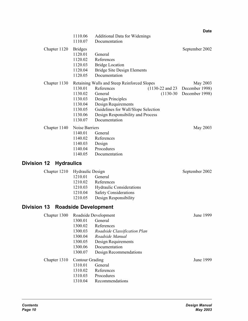
Date1110.06 Additional Data for Widenings1110.07 Documentation
Chapter 1120 Bridges September 20021120.01 General1120.02 References1120.03 Bridge Location1120.04 Bridge Site Design Elements1120.05 Documentation
Chapter 1130 Retaining Walls and Steep Reinforced Slopes May 20031130.01 References (1130-22 and 23 December 1998)1130.02 General (1130-30 December 1998)1130.03 Design Principles1130.04 Design Requirements1130.05 Guidelines for Wall/Slope Selection1130.06 Design Responsibility and Process1130.07 Documentation
Chapter 1140 Noise Barriers May 20031140.01 General1140.02 References1140.03 Design1140.04 Procedures1140.05 Documentation
Division 12 HydraulicsChapter 1210 Hydraulic Design September 2002
1210.01 General1210.02 References1210.03 Hydraulic Considerations1210.04 Safety Considerations1210.05 Design Responsibility
Division 13 Roadside DevelopmentChapter 1300 Roadside Development June 1999
1300.01 General1300.02 References1300.03 Roadside Classification Plan1300.04 Roadside Manual1300.05 Design Requirements1300.06 Documentation1300.07 Design Recommendations
Chapter 1310 Contour Grading June 19991310.01 General1310.02 References1310.03 Procedures1310.04 Recommendations

Design Manual ContentsMay 2003 Page 11
Date
Chapter 1320 Vegetation June 19991320.01 General1320.02 References1320.03 Discussion1320.04 Recommendations1320.05 Design Guidelines1320.06 Documentation
Chapter 1330 Irrigation June 19991330.01 General1330.02 References1330.03 Design Considerations
Chapter 1350 Soil Bioengineering May 20001350.01 General1350.02 References1350.03 Uses1350.04 Design Responsibilities and Considerations1350.05 Documentation
Division 14 Right of Way and Access ControlChapter 1410 Right of Way Considerations June 1999
1410.01 General1410.02 References1410.03 Special Features1410.04 Easements and Permits1410.05 Programming for Funds1410.06 Appraisal and Acquisition1410.07 Transactions1410.08 Documentation
Chapter 1420 Access Control Design Policy June 19891420.01 General (1420-4 March 1994)1420.02 Full Access Control Criteria (1420-11 through 21 March 1994)1420.03 Partial Access Control Criteria1420.04 Modified Access Control Criteria1420.05 Access Approaches1420.06 Approaches Between Limited Access
Highways and Adjacent Railroads1420.07 Frontage Roads1420.08 Multiple Use of Right of Way for Nonhighway Purposes1420.09 Modifications to Established Limited Access Plans
Chapter 1425 Access Point Decision Report May 20001425.01 General1425.02 References1425.03 Definitions1425.04 Procedures1425.05 Access Point Decision Report and Supporting Analyses1425.06 Documentation

Contents Design ManualPage 12 May 2003
Date
Chapter 1430 Development of Access Control June 19891430.01 General1430.02 Access Report1430.03 Access Hearing
Chapter 1440 Surveying and Mapping June 19991440.01 General (1440-2 May 2001)1440.02 References1440.03 Procedures1440.04 Datums1440.05 Global Positioning System1440.06 WSDOT Monument Database1440.07 Geographic Information System1440.08 Photogrammetric Surveys1440.09 Documentation
Chapter 1450 Monumentation May 20011450.01 General1450.02 References1450.03 Definitions1450.04 Control Monuments1450.05 Alignment Monuments1450.06 Property Corners1450.07 Other Monuments1450.08 Documentation1450.09 Filing Requirements
Chapter 1460 Fencing September 20021460.01 General1460.02 References1460.03 Design Criteria1460.04 Fencing Types1460.05 Gates1460.06 Procedure1460.07 Documentation
Index May 2003

Design Manual ContentsMay 2003 Page 13
FiguresFigureNumber Title Page Last Date
120-1 Planning Organizations 120-3 May 2000120-2 Transportation Plan Relationships 120-17 May 2000120-3 RTIP, MTIP, and STIP Development Process 120-18 May 2000120-4 Planning and Programming Links 120-19 May 2000140-1 Overlapping Disciplines for Successful Project Delivery 140-1 September 2002140-2 Project Management Trade-Off Triangle 140-1 September 2002140-3 Relative Effort 140-3 September 2002140-4 Managing Project Delivery Steps and Elements 140-4 September 2002140-5 Risk Probability – Impact Matrix 140-9 September 2002140-6 Change Management Form 140-15 September 2002140-7a Task Planning Worksheet 140-16 September 2002140-7b Task Planning Worksheet 140-17 September 2002
210-1 Sequence for a Hearing 210-16 December 1998220-1 Environmental Process Flow Chart 220-14 June 1989240-1a Permits and Approvals 240-11 September 1990240-1b Permits and Approvals 240-12 September 1990240-2 FAA Notice Requirement Related to Highways 240-13 June 1989240-3 DNR Area Management Units 240-14 June 1989
315-1 Eight-Phase Job Plan for VE Studies 315-5 August 1998315-2 Request for Value Engineering Study 315-6 August 1998315-3 VE Study Team Tools 315-7 August 1998325-1 Design Matrix Selection Guide 325-4 May 2001325-2a NHS Highways in Washington 325-6 February 2002325-2b NHS Highways in Washington (continued) 325-7 February 2002325-3a Preservation Program 325-8 May 2001325-3b Improvement Program 325-9 May 2001325-3c Improvement Program (continued) 325-10 May 2001325-4 Design Matrix 1 — Interstate Routes (Main Line) 325-11 September 2002325-5 Design Matrix 2 — Interstate Interchange Areas 325-12 September 2002325-6 Design Matrix 3 — NHS Routes (Main Line) 325-13 September 2002325-7 Design Matrix 4 — Non-Interstate Interchange Areas 325-14 September 2002325-8 Design Matrix 5 — Non-NHS Routes 325-15 September 2002330-1 Design Approval Level 330-7 May 2001330-2 Reviews and Approvals 330-8 May 2001330-3a Reviews and Approvals, Design 330-9 May 2001330-3b Reviews and Approvals, Design (continued) 330-10 May 2001330-4 PS&E Process Approvals 330-11 May 2001330-5a Sample Project Analysis 330-12 May 2001330-5b Sample Project Analysis 330-13 May 2001330-6 Deviation and Evaluate Upgrade Request/Documentation
Content List 330-14 May 2001

Contents Design ManualPage 14 May 2003
340-1 Minor Operational Enhancement Matrix Selection Guide 340-4 September 2002340-2 Minor Operational Enhancement Matrix 1
Interstate & NHS Freeway Routes 340-7 September 2002340-3 Minor Operational Enhancement Matrix 2
NHS Nonfreeway Routes 340-8 September 2002340-4 Minor Operational Enhancement Matrix 3
Non-NHS Routes 340-9 September 2002340-5a Q Project Design Summary/Approval Template 340-10 September 2002340-5b Q Project Design Summary/Approval Template 340-11 September 2002430-1 Turning Ramp Lane Widths Modified Design Level 430-1 May 2001430-2 Design Vehicles Modified Design Level 430-3 May 2001430-3 Modified Design Level for Multilane Highways and Bridges 430-4 May 2001430-4 Modified Design Level for Two-Lane Highways and Bridges 430-5 May 2001430-5 Minimum Total Roadway Widths for Two-Lane
Highway Curves — Modified Design Level 430-6 May 2001430-6 Minimum Total Roadway Widths for Two-Lane
Highway Curves, D<90º— Modified Design Level 430-7 May 2001430-7 Evaluation for Stopping Sight Distance for Crest Vertical
Curves — Modified Design Level 430-8 May 2001430-8 Evaluation for Stopping Sight Distance for Horizontal
Curves — Modified Design Level 430-9 May 2001430-9 Main Line Roadway Sections — Modified Design Level 430-10 February 2002430-10 Ramp Roadway Sections — Modified Design Level 430-11 May 2001440-1 Desirable Design Speed 440-4 May 2001440-2 Minimum Shoulder Width 440-5 May 2001440-3 Shoulder Width for Curb 440-6 May 2001440-4 Geometric Design Data, Interstate 440-9 May 2001440-5a Geometric Design Data, Principal Arterial 440-10 May 2001440-5b Geometric Design Data, Principal Arterial 440-11 May 2001440-6a Geometric Design Data, Minor Arterial 440-12 May 2001440-6b Geometric Design Data, Minor Arterial 440-13 May 2001440-7a Geometric Design Data, Collector 440-14 May 2001440-7b Geometric Design Data, Collector 440-15 May 2001
510-1 Material Source Development Plan 510-16 November 1999520-1 Estimating — Miscellaneous Tables 520-2 February 2002520-2a Estimating — Asphalt Concrete Pavement and Asphalt
Distribution Tables 520-3 February 2002520-2b Estimating — Asphalt Concrete Pavement and Asphalt
Distribution Tables 520-4 February 2002520-3 Estimating — Bituminous Surface Treatment 520-5 February 2002520-4 Estimating — Base and Surfacing Typical Section
Formulae and Example 520-6 February 2002520-5a Estimating — Base and Surfacing Quantities 520-7 April 1998520-5b Estimating — Base and Surfacing Quantities 520-8 April 1998520-5c Estimating — Base and Surfacing Quantities 520-9 April 1998520-5d Estimating — Base and Surfacing Quantities 520-10 April 1998520-5e Estimating — Base and Surfacing Quantities 520-11 April 1998
FigureNumber Title Page Last Date

Design Manual ContentsMay 2003 Page 15
520-5f Estimating — Base and Surfacing Quantities 520-12 April 1998520-5g Estimating — Base and Surfacing Quantities 520-13 April 1998520-5h Estimating — Base and Surfacing Quantities 520-14 April 1998530-1 Selection Criteria for Geotextile Class 530-3 April 1998530-2 Maximum Sheet Flow Lengths for Silt Fences 530-8 April 1998530-3 Maximum Contributing Area for Ditch and
Swale Applications 530-8 April 1998530-4 Design Process for Drainage and Erosion Control
Geotextiles and Nonstandard Applications 530-12 April 1998530-5 Design Process for Separation, Soil Stabilization,
and Silt Fence 530-13 November 1999530-6a Examples of Various Geosynthetics 530-14 April 1998530-6b Examples of Various Geosynthetics 530-15 April 1998530-7a Geotextile Application Examples 530-16 April 1998530-7b Geotextile Application Examples 530-17 April 1998530-7c Geotextile Application Examples 530-18 April 1998530-7d Geotextile Application Examples 530-19 April 1998530-8 Definition of Slope Length 530-20 April 1998530-9 Definition of Ditch or Swale Storage Length
and Width 530-21 April 1998530-10 Silt Fences for Large Contributing Area 530-22 April 1998530-11 Silt Fence End Treatment 530-23 April 1998530-12 Gravel Check Dams for Silt Fences 530-24 April 1998
610-1 Type of Area and Appropriate Level of Service 610-3 June 1989610-2 Adjustment Factor for Type of Multilane Highway and
Development Environment, fE 610-3 June 1989610-3 Maximum ADT vs. Level of Service and Type of Terrain
for Two-Lane Rural Highways 610-4 June 1989610-4 Service Flow Rate per Lane (SFL) for Multilane Highways 610-5 June 1989610-5 Peak-Hour Factors 610-6 June 1989610-6 Service Flow Rates per Lane (SFL) for Freeways 610-6 June 1989620-1a Alignment Examples 620-6 April 1998620-1b Alignment Examples 620-7 April 1998620-1c Alignment Examples 620-8 April 1998630-1a Coordination of Horizontal and Vertical Alignments 630-4 April 1998630-1b Coordination of Horizontal and Vertical Alignments 630-5 April 1998630-1c Coordination of Horizontal and Vertical Alignments 630-6 April 1998630-2 Grade Length 630-7 April 1998630-3 Grading at Railroad Crossings 630-8 April 1998640-1 Minimum Radius for Normal Crown Section 640-5 February 2002640-2 Side Friction Factor 640-5 February 2002640-3 Divided Highway Roadway Sections 640-10 February 2002640-4 Undivided Multilane Highway Roadway Sections 640-11 February 2002640-5 Two-Lane Highway Roadway Sections 640-12 February 2002640-6a Ramp Roadway Sections 640-13 February 2002640-6b Ramp Roadway Sections 640-14 February 2002
FigureNumber Title Page Last Date

Contents Design ManualPage 16 May 2003
640-7a Traveled Way Width for Two-Way Two-LaneTurning Roadways 640-15 February 2002
640-7b Traveled Way Width for Two-Way Two-LaneTurning Roadways 640-16 February 2002
640-8a Traveled Way Width for Two-Lane One-WayTurning Roadways 640-17 February 2002
640-8b Traveled Way Width for Two-Lane One-WayTurning Roadways 640-18 February 2002
640-9a Traveled Way Width for One-Lane Turning Roadways 640-19 February 2002640-9b Traveled Way Width for One-Lane Turning Roadways 640-20 February 2002640-9c Traveled Way Width for One-Lane Turning Roadways 640-21 February 2002640-10a Shoulder Details 640-22 February 2002640-10b Shoulder Details 640-23 February 2002640-11a Superelevation Rates (10% Max) 640-24 February 2002640-11b Superelevation Rates (6% Max) 640-25 February 2002640-11c Superelevation Rates (8% Max) 640-26 February 2002640-12 Superelevation Rates for Turning Roadways
at Intersections 640-27 February 2002640-13a Superelevation Transitions for Highway Curves 640-28 February 2002640-13b Superelevation Transitions for Highway Curves 640-29 February 2002640-13c Superelevation Transitions for Highway Curves 640-30 February 2002640-13d Superelevation Transitions for Highway Curves 640-31 February 2002640-13e Superelevation Transitions for Highway Curves 640-32 February 2002640-14a Superelevation Transitions for Ramp Curves 640-33 February 2002640-14b Superelevation Transitions for Ramp Curves 640-34 February 2002640-15a Divided Highway Median Sections 640-35 February 2002640-15b Divided Highway Median Sections 640-36 February 2002640-15c Divided Highway Median Sections 640-37 February 2002640-16a Roadway Sections in Rock Cuts, Design A 640-38 February 2002640-16b Roadway Sections in Rock Cuts, Design B 640-39 February 2002640-17 Roadway Sections With Stepped Slopes 640-40 February 2002640-18a Bridge End Slopes 640-41 February 2002640-18b Bridge End Slopes 640-42 February 2002650-1 Passing Sight Distance 650-1 April 1998650-2 Design Stopping Sight Distance 650-3 June 1999650-3 Existing Stopping Sight Distance 650-3 June 1999650-4 Design Stopping Sight Distance on Grades 650-3 June 1999650-5 Decision Sight Distance 650-5 April 1998650-6 Passing Sight Distance for Crest Vertical Curves 650-6 April 1998650-7 Stopping Sight Distance for Crest Vertical Curves 650-7 April 1998650-8 Stopping Sight Distance for Sag Vertical Curves 650-8 May 2000650-9 Horizontal Stopping Sight Distance 650-9 May 2001
700-1 Design Clear Zone Distance Table 700-10 May 2003700-2a Design Clear Zone Inventory Form 700-11 May 2003700-2b Design Clear Zone Inventory Form 700-12 May 2003700-3 Recovery Area 700-13 May 2003
FigureNumber Title Page Last Date

Design Manual ContentsMay 2003 Page 17
700-4 Design Clear Zone for Ditch Sections 700-14 May 2003700-5 Guidelines for Embankment Barrier 700-15 May 2003700-6 Mailbox Location and Turnout Design 700-16 May 2003700-7 Glare Screens 700-17 May 2003710-1 Type 7 Bridge Rail Upgrade Criteria 710-3 May 2000710-2 Longitudinal Barrier Deflection 710-4 May 2000710-3 Longitudinal Barrier Flare Rates 710-5 May 2000710-4 Guardrail Locations on Slopes 710-6 May 2000710-5 Old Type 3 Anchor 710-8 May 2000710-6 Guardrail Connections 710-9 May 2000710-7 Transitions and Connections 710-10 May 2000710-8 Concrete Barrier Shapes 710-12 May 2000710-9 Single Slope Concrete Barrier 710-13 May 2000710-10 Safety Shaped Concrete Bridge Rail Retrofit 710-16 May 2000710-11a Barrier Length of Need 710-18 May 2000710-11b Barrier Length of Need 710-19 May 2000710-11c Barrier Length of Need on Curves 710-20 May 2000710-12 Beam Guardrail Post Installation 710-21 May 2000710-13 Beam Guardrail Terminals 710-22 May 2000710-14 Cable Barrier Locations on Slopes 710-23 May 2000710-15 Thrie Beam Bridge Rail Retrofit Criteria 710-24 May 2000720-1 Impact Attenuator Sizes 720-6 September 2002720-2a Impact Attenuator Systems — Permanent Installations 720-8 September 2002720-2b Impact Attenuator Systems — Permanent Installations 720-9 September 2002720-2c Impact Attenuator Systems — Permanent Installations 720-10 September 2002720-2d Impact Attenuator Systems — Permanent Installations 720-11 September 2002720-3 Impact Attenuator Systems — Work Zone Installations 720-12 September 2002720-4a Impact Attenuator Systems — Older Systems 720-13 September 2002720-4b Impact Attenuator Systems — Older Systems 720-14 September 2002720-5 Impact Attenuator Comparison 720-15 September 2002
810-1a Work Zone Types 810-13 February 2002810-1b Work Zone Types 810-14 February 2002810-1c Work Zone Types 810-15 February 2002810-2a Sign Placement — Rural Areas 810-16 February 2002810-2b Sign Placement — Urban Areas 810-17 February 2002810-3 Channelization Devices 810-18 February 2002810-4 Barricade Types 810-19 February 2002810-5 Barrier Delineators 810-20 February 2002820-1a Sign Support Locations 820-5 November 1999820-1b Sign Support Locations 820-6 November 1999820-2 Wood Posts 820-7 November 1999820-3 Steel Posts 820-8 November 1999820-4 Laminated Wood Box Posts 820-9 November 1999830-1 Pavement Marking Material Guide 830-6 May 2000830-2 Guide Post Placement 830-7 May 2000830-3 Wildlife Reflectors on a Tangent Section 830-8 May 2000
FigureNumber Title Page Last Date

Contents Design ManualPage 18 May 2003
830-4 Wildlife Reflectors on the Outside of a Curve 830-8 May 2000840-1 Freeway Lighting Applications 840-11 May 2000840-2 Freeway Lighting Applications 840-12 May 2000840-3 Roadway Lighting Applications 840-13 May 2000840-4 Roadway Lighting Applications 840-14 May 2000840-5 Roadway Lighting Applications 840-15 May 2000840-6 Light Levels and Uniformity Ratios 840-16 May 2000840-7 Light Standard Locations 840-17 May 2000840-8 Light Standard Heights, Conductor, and Conduit Properties 840-18 May 2000840-9a Line Loss Calculations 840-19 May 2000840-9b Line Loss Calculations 840-20 May 2000840-10a Illumination Calculation Example 840-21 May 2000840-10b Illumination Calculation Example 840-22 May 2000840-10c Illumination Calculation Example 840-23 May 2000840-10d Illumination Calculation Example 840-24 May 2000850-1 Signal Display Maximum Heights 850-13 May 2001850-2 Signal Display Areas 850-14 May 2001850-3 Responsibility for Facilities 850-17 May 2001850-4 Standard Intersection Movements and Head Numbers 850-18 May 2001850-5 Phase Diagrams-Four Way Intersections 850-19 May 2001850-6 Turn Lane Configuration Preventing Concurrent Phasing
Double Left Turn Channelization 850-20 May 2001850-7 Railroad Preemption Phasing 850-21 May 2001850-8a Pedestrian Push Button Locations 850-22 May 2001850-8b Pedestrian Push Button Locations 850-23 May 2001850-9 Dilemma Zone Loop Placement 850-24 May 2001850-10 Railroad Queue Clearance 850-25 May 2001850-11a Intersections With Railroad Crossings 850-26 May 2001850-11b Intersections With Railroad Crossings 850-27 May 2001850-12a Traffic Signal Display Placements 850-28 May 2001850-12b Traffic Signal Display Placements 850-29 May 2001850-12c Traffic Signal Display Placements 850-30 May 2001850-12d Traffic Signal Display Placements 850-31 May 2001850-12e Traffic Signal Display Placements 850-32 May 2001850-13 Mast Arm Signal Moment and Foundation Depths 850-33 May 2001850-14a Strain Pole and Foundation Selection Procedure 850-34 May 2001850-14b Strain Pole and Foundation Selection Procedure 850-35 May 2001850-15 Strain Pole and Foundation Selection Example 850-36 May 2001850-16 Conduit and Conductor Sizes 850-37 May 2001
910-1 Minimum Intersection Spacing 910-4 May 2001910-2 Design Vehicle Types 910-4 May 2001910-3 Intersection Design Vehicle 910-5 May 2001910-4 Left-Turn Storage With Trucks (ft) 910-7 May 2001910-5 U-Turn Spacing 910-10 February 2002910-6 Sight Distance for Turning Vehicles 910-11 May 2001910-7a Turning Path Template 910-14 May 2001
FigureNumber Title Page Last Date

Design Manual ContentsMay 2003 Page 19
910-7b Turning Path Template 910-15 May 2001910-7c Turning Path Template 910-16 May 2001910-8 Right-Turn Corner 910-17 May 2001910-9a Left-Turn Storage Guidelines (Two-Lane, Unsignalized) 910-18 May 2001910-9b Left-Turn Storage Guidelines (Four-Lane, Unsignalized) 910-19 May 2001910-10a Left-Turn Storage Length (Two-Lane, Unsignalized) 910-20 May 2001910-10b Left-Turn Storage Length (Two-Lane, Unsignalized) 910-21 May 2001910-10c Left-Turn Storage Length (Two-Lane, Unsignalized) 910-22 May 2001910-11a Median Channelization (Widening) 910-23 February 2002910-11b Median Channelization — Median Width 23 ft to 26 ft 910-24 February 2002910-11c Median Channelization — Median Width of More Than 26 ft 910-25 February 2002910-11d Median Channelization (Minor Intersection) 910-26 May 2001910-11e Median Channelization (Two-Way Left-Turn Lane) 910-27 May 2001910-12 Right-Turn Lane Guidelines 910-28 May 2001910-13 Right-Turn Pocket and Right-Turn Taper 910-29 February 2002910-14 Right-Turn Lane 910-30 February 2002910-15 Acceleration Lane 910-31 May 2001910-16a Traffic Island Designs 910-32 May 2001910-16b Traffic Island Designs (Compound Curve) 910-33 May 2001910-16c Traffic Island Designs 910-34 May 2001910-17 U-Turn Locations 910-35 May 2001910-18a Sight Distance for Grade Intersection With Stop Control 910-36 May 2001910-18b Sight Distance at Intersections 910-37 May 2001910-19 Interchange Ramp Details 910-38 May 2001915-1 Roundabout Elements 915-3 February 2002915-2 Entry Angle 915-4 February 2002915-3 Turning Radius (R) 915-5 February 2002915-4 Deflection 915-8 February 2002915-5 Stopping Sight Distance for Roundabouts 915-10 February 2002915-6 Roundabout Categories Design Characteristics 915-16 February 2002915-7 Approximate Entry Capacity 915-17 February 2002915-8a Deflection Path 915-18 February 2002915-8b Deflection Path 915-19 February 2002915-9 Deflection Path Radius 915-20 February 2002915-10 Entry and Exit 915-21 February 2002915-11 Path Overlap 915-22 February 2002915-12 Roundabout Intersection Sight Distance 915-23 February 2002915-13 Central Island 915-24 February 2002915-14 Splitter Island 915-25 February 2002915-15 Shared Use Sidewalk 915-26 February 2002915-16 Roundabout Signing 915-27 February 2002915-17 Roundabout Pavement Marking 915-28 February 2002915-18 Roundabout Illumination 915-29 February 2002920-1 Road Approach Design Templates 920-3 April 1998920-2 Minimum Corner Clearance 920-4 April 1998920-3 Noncommercial Approach Design Template A 920-5 November 1999920-4 Noncommercial Approach Design Template B and C 920-6 November 1999
FigureNumber Title Page Last Date

Contents Design ManualPage 20 May 2003
920-5 Commercial Approach — Single ApproachDesign Template D 920-7 April 1998
920-6 Road Approach Sight Distance 920-8 May 2001920-7 Road Approach Spacing and Corner Clearance 920-9 May 2001930-1 M Sight Distance at Railroad Crossing 930-4 March 1994930-2 Guidelines for Railroad Crossing Protection 930-5 June 1989930-3 M Typical Pullout Lane at Railroad Crossing 930-6 March 1994930-4 M Railroad Crossing Plan for Washington Utilities and
Transportation Commission 930-7 March 1994930-5 M Longitudinal Easement Cross Sections 930-8 March 1994930-1 Sight Distance at Railroad Crossing 930-9 March 1994930-3 Typical Pullout Lane at Railroad Crossing 930-10 March 1994930-4 Railroad Crossing Plan for Washington Utilities and
Transportation Commission 930-11 March 1994930-5 Longitudinal Easement Cross Sections 930-12 March 1994940-1 Ramp Design Speed 940-5 September 2002940-2 Maximum Ramp Grade 940-5 September 2002940-3 Ramp Widths (ft) 940-5 September 2002940-4 Basic Interchange Patterns 940-12 September 2002940-5 Minimum Ramp Connection Spacing 940-13 September 2002940-6a Lane Balance 940-14 September 2002940-6b Lane Balance 940-15 September 2002940-7 Main Line Lane Reduction Alternatives 940-16 September 2002940-8 Acceleration Lane Length 940-17 September 2002940-9a On-Connection (Single-Lane, Taper Type) 940-18 September 2002940-9b On-Connection (Single-Lane, Parallel Type) 940-19 September 2002940-9c On-Connection (Two-Lane, Parallel Type) 940-20 September 2002940-9d On-Connection (Two-Lane, Taper Type) 940-21 September 2002940-10 Deceleration Lane Length 940-22 September 2002940-11a Gore Area Characteristics 940-23 September 2002940-11b Gore Area Characteristics 940-24 September 2002940-12a Off-Connection (Single-Lane, Taper Type) 940-25 September 2002940-12b Off-Connection (Single-Lane, Parallel Type) 940-26 September 2002940-12c Off-Connection (Single-Lane, One-Lane Reduction) 940-27 September 2002940-12d Off-Connection (Two-Lane, Taper Type) 940-28 September 2002940-12e Off-Connection (Two-Lane, Parallel Type) 940-29 September 2002940-13a Collector Distributor (Outer Separations) 940-30 September 2002940-13b Collector Distributor (Off-Connections) 940-31 September 2002940-13c Collector Distributor (On-Connections) 940-32 September 2002940-14 Loop Ramps Connections 940-33 September 2002940-15 Length of Weaving Sections 940-34 September 2002940-16 Temporary Ramps 940-35 September 2002940-17 Interchange Plan 940-36 September 2002
1010-1 Rolling Resistance 1010-4 November 19991010-2a Performance for Heavy Trucks 1010-6 November 19991010-2b Speed Reduction Example 1010-7 November 1999
FigureNumber Title Page Last Date

Design Manual ContentsMay 2003 Page 21
1010-3 Level of Service — Multilane 1010-8 May 20011010-4 Auxiliary Climbing Lane 1010-9 November 19991010-5 Warrant for Passing Lanes 1010-10 November 19991010-6 Auxiliary Passing Lane 1010-11 November 19991010-7 Slow Moving Vehicle Turnout 1010-12 November 19991010-8 Typical Emergency Escape Ramp 1010-13 November 19991010-9 Chain-Up/Chain-Off Area 1010-14 November 19991020-1 Shared Use Path 1020-3 May 20011020-2 Bike Lane 1020-4 May 20011020-3 Shared Roadway 1020-4 May 20011020-4 Signed Shared Roadway (Designated Bike Route) 1020-5 May 20011020-5 Obstruction Marking 1020-8 May 20011020-6 Midblock Type Shared Use Path Crossing 1020-9 May 20011020-7 Typical Redesign of a Diagonal Midblock Crossing 1020-10 May 20011020-8 Adjacent Shared Use Path Intersection 1020-11 May 20011020-9 Railroad Crossing for Shared Used Path 1020-12 May 20011020-10 Bicycle Design Speeds 1020-13 May 20011020-11 Bikeway Curve Widening 1020-13 May 20011020-12 R Values and Subsurfacing Needs 1020-14 May 20011020-13 Two-Way Shared Use Path on Separate Right of Way 1020-18 May 20011020-14 Two-Way Shared Use Path Adjacent to Roadway 1020-19 May 20011020-15 Typical Bike Lane Cross Sections 1020-20 May 20011020-16 Bikeways on Highway Bridges 1020-21 May 20011020-17 Refuge Area 1020-22 May 20011020-18 At-Grade Railroad Crossings 1020-23 May 20011020-19 Stopping Sight Distance 1020-24 May 20011020-20 Sight Distance for Crest Vertical Curves 1020-25 September 20021020-21 Lateral Clearance on Horizontal Curves 1020-26 September 20021020-22 Typical Bicycle/Auto Movements at Intersection
of Multilane Streets 1020-27 May 20011020-23a Bicycle Crossing of Interchange Ramp 1020-28 May 20011020-23b Bicycle Crossing of Interchange Ramp 1020-29 May 20011020-24 Bike Lanes Approaching Motorists’ Right-Turn-Only Lanes 1020-30 May 20011020-25 Typical Pavement Marking for Bike Lane on
Two-Way Street 1020-31 May 20011020-26 Typical Bike Lane Pavement Markings at T-Intersections 1020-32 May 20011025-1 Trail Width and Grades 1025-5 May 20011025-2a Pedestrian Walkways 1025-10 May 20011025-2b Pedestrian Walkways 1025-11 May 20011025-3 Sidewalk Recommendations 1025-12 May 20011025-4 Marked Crosswalk Recommendations at Unsignalized
Pedestrian Crossings 1025-13 May 20011025-5 Crosswalk Locations 1025-14 May 20011025-6a Sight Distance at Intersections 1025-15 May 20011025-6b Sight Distance at Intersections 1025-16 May 20011025-7 Sidewalk Bulb Outs 1025-17 May 20011025-8 Midblock Pedestrian Crossing 1025-18 May 20011025-9 Sidewalk Ramp Drainage 1025-19 May 2001
FigureNumber Title Page Last Date

Contents Design ManualPage 22 May 2003
1030-1 Typical Truck Storage 1030-3 November 19991030-2 Typical Single RV Dump Station Layout 1030-4 November 19991030-3 Typical Two RV Dump Station Layout 1030-5 November 19991040-1 Truck Weigh Site (Multilane Highways) 1040-6 May 20001040-2 Truck Weigh Site (Two Lane Highways) 1040-7 May 20001040-3 Vehicle Inspection Installation 1040-8 May 20001040-4 Minor Portable Scale Site 1040-9 May 20001040-5 Major Portable Scale Site 1040-10 May 20001040-6 Small Shoulder Site 1040-11 May 20001040-7 Large Shoulder Site 1040-12 May 20001040-8a MOU Related to Vehicle Weighing and Equipment
Inspection Facilities on State Highways 1040-13 May 20001040-8b MOU Related to Vehicle Weighing and Equipment
Inspection Facilities on State Highways 1040-14 May 20001040-8c MOU Related to Vehicle Weighing and Equipment
Inspection Facilities on State Highways 1040-15 May 20001040-8d MOU Related to Vehicle Weighing and Equipment
Inspection Facilities on State Highways 1040-16 May 20001040-8e MOU Related to Vehicle Weighing and Equipment
Inspection Facilities on State Highways 1040-17 May 20001050-1 Minimum Traveled Way Widths for Articulated Buses 1050-8 May 20031050-2 Typical HOV Lane Sections 1050-11 May 20031050-3 Roadway Widths for Two-Lane Ramps with an HOV Lane 1050-12 May 20031050-4a Single-Lane Ramp Meter With HOV Bypass 1050-13 May 20031050-4b Two-Lane Ramp Meter With HOV Bypass 1050-14 May 20031050-5a Enforcement Area (One Direction Only) 1050-15 May 20031050-5b Enforcement Area (Median) 1050-16 May 20031060-1 M Bus Berth Designs 1060-14 March 19941060-2 Transit Center Sawtooth Bus Berth Design Example 1060-15 December 19911060-3 M Bus Turnout Transfer Center 1060-16 March 19941060-4 M Off-Street Transfer Center 1060-17 March 19941060-5 M Minimum Bus Zone Dimensions 1060-18 March 19941060-6 Bus Stop Pullouts, Arterial Streets 1060-19 November 19971060-7 M Minimum Bus Zone and Pullout after Right Turn
Dimensions 1060-20 March 19941060-8 M Shelter Siting 1060-21 March 19941060-9 M Typical Bus Shelter Design 1060-22 March 19941060-10 M Design Vehicle Turning Movements 1060-23 July 19941060-11 M Turning Template for Articulated Bus 1060-24 July 19941060-12 M Intersection Design 1060-25 March 19941060-13 M Cross-Street Width Occupied by Turning Vehicle
for Various Angles of Intersection and Curb Radii 1060-26 March 19941060-1 Bus Berth Designs 1060-27 March 19941060-3 Bus Turnout Transfer Center 1060-28 March 19941060-4 Off-Street Transfer Center 1060-29 March 19941060-5 Minimum Bus Zone Dimensions 1060-30 March 19941060-6 Bus Stop Pullouts, Arterial Streets 1060-31 March 1994
FigureNumber Title Page Last Date

Design Manual ContentsMay 2003 Page 23
1060-7 Minimum Bus Zone and Pullout after Right TurnDimensions 1060-32 March 1994
1060-8 Shelter Siting 1060-33 March 19941060-9 Typical Bus Shelter Design 1060-34 March 19941060-10 Design Vehicle Turning Movements 1060-35 July 19941060-11 Turning Template for Articulated Bus 1060-36 July 19941060-12 Intersection Design 1060-37 March 19941060-13 Cross-Street Width Occupied by Turning Vehicle
for Various Angles of Intersection and Curb Radii 1060-38 March 1994
1110-1 Bridge Site Data Check List 1110-5 November 19991120-1 Bridge Vertical Clearances 1120-4 September 20021120-2a Railroad Vertical Clearance for New Bridge Construction 1120-6 September 20021120-2b Railroad Vertical Clearance for Existing Bridge
Modifications 1120-7 September 20021130-1a Typical Mechanically Stabilized Earth Gravity Walls 1130-22 December 19981130-1b Typical Prefabricated Modular Gravity Walls 1130-23 December 19981130-1c Typical Rigid Gravity, Semigravity Cantilever,
Nongravity Cantilever, and Anchored Walls 1130-24 May 20031130-1d Typical Rockery and Reinforced Slope 1130-25 May 20031130-2 MSE Wall Drainage Detail 1130-26 May 20031130-3 Retaining Walls With Traffic Barriers 1130-27 May 20031130-4a Retaining Wall Design Process 1130-28 May 20031130-4b Retaining Wall Design Process — Proprietary 1130-29 May 20031130-5 Retaining Wall Bearing Pressure 1130-30 December 19981140-1 Standard Noise Wall Types 1140-3 May 20031410-1 Appraisal and Acquisition 1410-6 June 19991420-1a Full Access Control Criteria 1420-10 June 19891420-1b M Access Control for Typical Interchange 1420-11 March 19941420-1c M Access Control at Ramp Termination 1420-12 March 19941420-2a M Partial Access Control Criteria 1420-13 March 19941420-2b M Access Control for Intersection at Grade 1420-14 March 19941420-3 M Access Control Limits at Intersections 1420-15 March 19941420-1b Access Control for Typical Interchange 1420-17 March 19941420-1c Access Control at Ramp Termination 1420-18 March 19941420-2a Partial Access Control Criteria 1420-19 March 19941420-2b Access Control for Intersection at Grade 1420-20 March 19941420-3 Access Control Limits at Intersections 1420-21 March 19941425-1a Access Point Decision Report Content and Review Levels 1425-11 May 20001425-1b Access Point Decision Report Content and Review Levels 1425-12 May 20001425-2 Access Point Decision Report Possibly Not Required 1425-13 May 20001425-3a Access Point Decision Report Flow Chart 1425-14 May 20001425-3b Access Point Decision Report Flow Chart 1425-15 May 20001430-1 Access Report Plan 1430-4 June 19891430-2 Access Hearing Plan 1430-5 June 19891440-1a Interagency Agreement 1440-4 June 1999
FigureNumber Title Page Last Date

Contents Design ManualPage 24 May 2003
FigureNumber Title Page Last Date1440-1b Interagency Agreement 1440-5 June 19991450-1 Monument Documentation Summary 1450-4 May 20011450-2a DNR Permit Application 1450-5 May 20011450-2b DNR Completion Record Form 1450-6 May 20011450-3a Land Corner Record 1450-7 May 20011450-3b Land Corner Record 1450-8 May 2001
Design Manual Roadside SafetyMay 2003 Page 700-1
Chapter 700 Roadside Safety
700.01 General700.02 References700.03 Definitions700.04 Clear Zone700.05 Hazards to Be Considered for Mitigation700.06 Median Considerations700.07 Other Roadside Safety Features700.08 Documentation
700.01 GeneralRoadside safety addresses the area outside of the roadway and is an important component of total highway design. There are numerous reasons why a vehicle leaves the roadway. Regardless of the reason, a forgiving roadside can reduce the seriousness of the consequences of a roadside encroachment. From a safety perspective, the ideal highway has roadsides and median areas that are flat and unobstructed by hazards.
Elements such as side slopes, fixed objects, and water are potential hazards that a vehicle might encounter when it leaves the roadway. These hazards present varying degrees of danger to the vehicle and its occupants. Unfortunately, geography and economics do not always allow ideal highway conditions. The mitigative measures to be taken depend on the probability of an accident occurring, the likely severity, and the available resources.
In order of preference, mitigative measures are: removal, relocation, reduction of impact severity (using breakaway features or making it traversable), and shielding with a traffic barrier. Consider cost (initial and life cycle costs) and maintenance requirements in addition to accident severity when selecting a mitigative measure. Use traffic barriers only when other measures cannot reasonably be accomplished. See Chapter 710 for additional information on traffic barriers.
700.02 ReferencesA Policy on Geometric Design of Highways and Streets (Green Book), AASHTO, 2001
Revised Code of Washington (RCW) 47.24.020(2), “Jurisdiction, control”
RCW 47.32.130, “Dangerous objects and structures as nuisances”
City and County Design Standards (contained in the Local Agency Guidelines, M 36-63), WSDOT
Roadside Design Guide, AASHTO, 2002
Roadside Manual, M 25-30, WSDOT
Standard Plans for Road, Bridge, and Municipal Construction (Standard Plans), M 21-01, WSDOT
700.03 DefinitionsADT The average daily traffic for the design year under consideration.
clear run-out area The area beyond the toe of a nonrecoverable slope available for safe use by an errant vehicle.
clear zone The total roadside border area, starting at the edge of the traveled way, available for use by errant vehicles. This area may consist of a shoulder, a recoverable slope, a nonrecover-able slope, and/or a clear run-out area. The clear zone cannot contain a critical fill slope.
Design Clear Zone The minimum target value used in highway design.
critical fill slope A slope on which a vehicle is likely to overturn. Slopes steeper than 3H:1V are considered critical fill slopes.
hazard A side slope, a fixed object, or water that, when struck, can result in unacceptable impact forces on the vehicle occupants or place the occupants in a hazardous position. A hazard can be either natural or manmade.

Roadside Safety Design ManualPage 700-2 May 2003
Design Manual Roadside SafetyMay 2003 Page 700-3
nonrecoverable slope A slope on which an errant vehicle will continue until it reaches the bottom, without having the ability to recover control. Fill slopes steeper than 4H:1V, but no steeper than 3H:1V, are considered nonrecoverable.
recoverable slope A slope on which the driver of an errant vehicle can regain control of the vehicle. Slopes of 4H:1V or flatter are considered recoverable.
recovery area The minimum target value used in highway design when a fill slope between 4H:1V and 3H:1V starts within the Design Clear Zone.
traffic barrier A longitudinal barrier, including bridge rail or an impact attenuator, used to redirect vehicles from hazards located within an established Design Clear Zone, to prevent median crossovers, to prevent errant vehicles from going over the side of a bridge structure, or (occasionally), to protect workers, pedestrians, or bicyclists from vehicular traffic.
traveled way The portion of the roadway intended for the movement of vehicles, exclusive of shoulders and lanes for parking, turning, and storage for turning.
700.04 Clear ZoneA clear roadside border area is a primary consideration when analyzing potential roadside and median hazards (as defined in 700.05). The intent is to provide as much clear, traversable area for a vehicle to recover as practical. The Design Clear Zone is used to evaluate the adequacy of the existing clear area and proposed modifications of the roadside. When considering the placement of new objects along the roadside or median, evaluate the potential for impacts and try to select locations with the least likelihood of an impact by an errant vehicle.
(1) Design Clear Zone on All Limited Access State Highways and Other State Highways Outside Incorporated Cities and Towns
Evaluate the Design Clear Zone when the Clear Zone column on the design matrices (see Chapter 325) indicates evaluate upgrade (EU) or Full Design Level (F) or when considering the placement of a new fixed object on the roadside or median. Use the Design Clear Zone Inventory form (Figures 700-2a & 2b) to identify potential hazards and propose corrective actions.
Guidance for establishing the Design Clear Zone for highways outside of incorporated cities is provided in Figure 700-1. This guidance also applies to limited access state highways within the city limits. Providing a clear recovery area that is consistent with this guidance does not require any additional documentation. However, there might be situations where it is not practical to provide these recommended distances. In these situations, document the decision as a deviation as discussed in Chapter 330.
For additional Design Clear Zone guidance relating to roundabouts, see Chapter 915.
While not required, the designer is encouraged to evaluate potential hazards even when they are beyond the Design Clear Zone distances.
For state highways that are in an urban environment but outside of an incorporated city, evaluate both median and roadside clear zones as discussed above using Figure 700-1. However, there might be some flexibility in establishing the Design Clear Zone in urbanized areas adjacent to incorporated cities and towns. To achieve this flexibility, an evaluation of the impacts including safety, aesthetics, the environment, economics, modal needs, and access control can be used to establish the Design Clear Zone. This discussion, analysis, and agreement must take place early in the consideration of the median and roadside designs. An agreement on the responsibility for these median and roadside sections must be formalized with the city and/or county. The justification for the design decision for the selected Design Clear Zone must be documented as part of a project or corridor analysis. (See Chapter 330.)

Roadside Safety Design ManualPage 700-2 May 2003
Design Manual Roadside SafetyMay 2003 Page 700-3
(2) Design Clear Zone Inside Incorporated Cities and TownsFor managed access state highways within an urban area, it is recognized that in many cases it will not be practical to provide the Design Clear Zone distances shown in Figure 700-1. Roadways within an urban area generally have curbs and sidewalks and might have objects such as trees, poles, benches, trash cans, landscaping, and transit shelters along the roadside.
(a) Roadside. For managed access state highways, it is the city’s responsibility to establish an appropriate Design Clear Zone in accordance with guidance contained in the City and County Design Standards. Document, in the Design Documentation Package, the Design Clear Zone established by the city.
(b) Median. For managed access state highways with raised medians, the median’s Design Clear Zone is evaluated using Figure 700-1. In some instances, a median analysis will show that certain median designs provide significant benefits to overall corridor or project operations. In these cases, flexibility in establishing the Design Clear Zone is appropriate. To achieve this flexibility, an evaluation of the impacts (including safety, aesthetics, the environment, economics, modal needs, and access control) can be used to establish the median clear zone. This discussion, analysis, and agreement must take place early in the consideration of the flexible median design. An agreement on the responsibility for these median sections must be formalized with the city. The justification for the design decision for the selected Design Clear Zone must be documented as part of a project or corridor analysis. (See Chapter 330.)
(3) Design Clear Zone and CalculationsThe Design Clear Zone guidance provided in Figure 700-1 is a function of the posted speed, side slope, and traffic volume. There are no distances in the table for 3H:1V fill slopes. Although fill slopes between 4H:1V and 3H:1V are considered traversable if free of fixed objects, these slopes are defined as nonrecoverable slopes. A vehicle might be able to begin recovery on the shoulder, but will be unable to further this recovery until reaching a flatter area (4H:1V or flatter) at the toe of the slope. Under these conditions, the Design Clear Zone distance is called a recovery area. The method used to calculate the recovery area and an example are shown in Figure 700-3.
For ditch sections, the following criteria determine the Design Clear Zone:
(a) For ditch sections with fore slopes 4H:1V or flatter (see Figure 700-4, Case 1, for an example) the Design Clear Zone distance is the greater of the following:
• The Design Clear Zone distance for a 10H:1V cut section based on speed and the average daily traffic (ADT).
• A horizontal distance of 5 ft beyond the beginning of the back slope.
When a back slope steeper than 3H:1V continues for a horizontal distance of 5 ft beyond the beginning of the back slope, it is not necessary to use the 10H:1V cut slope criteria.
(b) For ditch sections with foreslopes steeper than 4H:1V, and back slopes steeper than 3H:1V the Design Clear Zone distance is 10 ft horizontal beyond the beginning of the back slope. (See Figure 700-4, Case 2, for an example.)
(c) For ditch sections with foreslopes steeper than 4H:1V and back slopes 3H:1V or flatter, the Design Clear Zone distance is the distance established using the recovery area formula (Figure 700-3). (See also Figure 700-4, Case 3, for an example.)

Roadside Safety Design ManualPage 700-4 May 2003
Design Manual Roadside SafetyMay 2003 Page 700-5
700.05 Hazards to Be Considered for MitigationThere are three general categories of hazards: side slopes, fixed objects, and water. The following sections provide guidance for determining when these obstacles present a significant hazard to an errant motorist. In addition, several conditions require special consideration:
• Locations with high accident rate histories.
• Locations with pedestrian and bicycle usage. See Chapters 1020, “Bicycle Facilities,” and 1025, “Pedestrian Design Considerations.”
• Playgrounds, monuments, and other locations with high social or economic value might require mitigation such as a barrier.
Use of a traffic barrier for hazards other than those described below requires justification in the Design Documentation Package.
(1) Side Slopes(a) Fill Slopes. Fill slopes can present a hazard to an errant vehicle with the degree of severity dependant upon the slope and height of the fill. Providing fill slopes that are 4H:1V or flatter can mitigate this hazard. If flattening the slope is not feasible or cost effective, the installation of a barrier might be appropriate. Figure 700-5 represents a selection procedure used to determine whether a fill side slope constitutes a hazard for which a barrier is a cost-effective mitigation. The curves are based on the severity indexes and represent the points where total costs associated with a traffic barrier are equal to the predicted accident cost associated with selected slope heights without traffic barrier. If the ADT and height of fill intersect on the “Barrier Recommended” side of the embankment slope curve, then provide a barrier if flattening the slope is not feasible or cost effective. Do not use Figure 700-5 for slope design. Design guidance for slopes is in Chapters 430 and 640. Also, if the figure indicates that barrier is not recommended at an existing slope, that result is not justification for a deviation.
For example, if the ADT is 4000 and the embankment height is 10 ft, barrier will be cost effective for a 2H:1V slope, but not for a 2.5H:1V slope.
This process only addresses the potential hazard of the slope. Obstacles on the slope can compound the hazard. Where barrier is not cost effective, use the recovery area formula to evaluate fixed objects on critical fill slopes less than 10 ft high.
(b) Cut Slopes. A cut slope is usually less of a hazard than a traffic barrier. The exception is a rock cut with a rough face that might cause vehicle snagging rather than providing relatively smooth redirection.
Analyze the potential motorist risk and the benefits of treatment of rough rock cuts located within the Design Clear Zone. A cost-effectiveness analysis that considers the consequences of doing nothing, removal, or smoothing of the cut slope, and all other viable options to reduce the severity of the hazard, can be used to determine the appropriate treatment. Some potential options are:
• Redirectional land form.
• Flexible barrier.
• More rigid barrier.
• Rumble strips.
Conduct an individual investigation for each rock cut or group of rock cuts. Select the most cost-effective treatment.
(2) Fixed ObjectsConsider the following objects for mitigation:
• Wooden poles or posts with cross sectional area greater than 16 square inches that do not have breakaway features.
• Nonbreakaway steel sign posts.
• Nonbreakaway light standards.
• Trees having a diameter of 4 in or more measured at 6 in above the ground surface.
• Fixed objects extending above the ground surface by more than 4 in; for example, boulders, concrete bridge rails, signal and electrical cabinets, piers, and retaining walls.
• Existing guardrail that does not conform to current design guidance. (See Chapter 710.)
• Drainage items, such as culvert and pipe ends.

Roadside Safety Design ManualPage 700-4 May 2003
Design Manual Roadside SafetyMay 2003 Page 700-5
Mitigate hazards that exist within the Design Clear Zone when feasible. Although limited in application, there may be situations where removal of hazard outside of the R.O.W is appropriate. The possible mitigative measures are listed below in order of preference.
• Remove.
• Relocate.
• Reduce impact severity (using a breakaway feature).
• Shield the object by using redirectional landform, longitudinal barrier, or impact attenuator.
(a) Trees. When evaluating new plantings or existing trees, consider the maximum allowable diameter of 4 in measured at 6 in above the ground when the tree has matured. When removing trees within the Design Clear Zone, complete removal of stumps is preferred. However, to avoid significant disturbance of the roadside vegetation, larger stumps may be mitigated by grinding or cutting them flush to the ground and grading around them. See the Roadside Manual for further guidance on the treatment of the disturbed roadside.
(b) Mailboxes. Ensure that all mailboxes located within the Design Clear Zone have supports and connections as shown in the Standard Plans. The height from the ground to the bottom of the mailbox is 3 ft 3 in. This height may vary from 3 ft 3 in to 4 ft if requested by the mail carrier. Include a note in the contract plans that gives the height desired if it is to be different from 3 ft 3 in. See Figure 700-6 for installation guidelines.
In urban areas where sidewalks are prevalent, contact the postal service to determine the most appropriate mailbox location. Locate mailboxes on limited access highways in accordance with the “Limited Access” Chapter in Division 14. A turnout, as shown on Figure 700-6, is not required on limited access highways with shoulders of 6 ft or more where only one mailbox is to be installed. On managed access highways, mailboxes must be on the right-hand side of the road in the direction of travel of the postal carrier. Avoid placing mailboxes along high-speed, high-volume highways. Locate Neighborhood Delivery and
Collection Box Units (NDCBUs) outside the Design Clear Zone.
(c) Culvert Ends. Provide a traversable end treatment when the culvert end section or opening is on the roadway side slope and within the Design Clear Zone. This can be accomplished for small culverts by beveling the end to match the side slope, with a maximum of 4 in extending out of the side slope.
Bars might be necessary to provide a traversable opening for larger culverts. Place bars in the plane of the culvert opening in accordance with the Standard Plans when:
1. Single cross culvert opening exceeds 40 in measured parallel to the direction of travel.
2. Multiple cross culvert openings that exceed 30 in each, measured parallel to the direction of travel.
3. Culvert approximately parallel to the roadway that has an opening exceeding 24 in measured perpendicular to the direction of travel.
Bars are permitted where they will not significantly affect the stream hydraulics and where debris drift is minor. Consult the regional Maintenance Office to verify these conditions. If debris drift is a concern, consider options to reduce the amount of debris that can enter the pipe. (See the Hydraulics Manual). Other treatments are extending the culvert to move the end outside the Design Clear Zone or installing a traffic barrier.
(d) Sign Posts. Whenever possible, locate signs behind existing or planned traffic barrier installations to eliminate the need for breakaway posts. Place them at least 25 ft from the end of the barrier terminal and with the sign face behind the barrier. When barrier is not present, use terrain features to reduce the likelihood of an errant vehicle striking the sign posts. Whenever possible, depending on the type of sign and the sign message, adjust the sign location to take advantage of barrier or terrain features. This will reduce accident potential and, possibly, future maintenance costs. See Chapter 820 for additional information regarding the placement of signs.

Roadside Safety Design ManualPage 700-6 May 2003
Design Manual Roadside SafetyMay 2003 Page 700-7
Sign posts with cross sectional areas greater than 16 square inches that are within the Design Clear Zone and not located behind a barrier must have breakaway features as shown in the Standard Plans.
(e) Traffic Signal Standards/Posts/Supports. Breakaway signal posts generally are not practical or desirable. Since these supports are generally located at intersecting roadways, there is a higher potential for a falling support to impact vehicles and/or pedestrians. In addition, signal supports that have overhead masts may be too heavy for a breakaway design to work properly. Other mitigation such as installing a traffic barrier is also very difficult. With vehicles approaching the support from many different angles, a barrier would have to surround the support and would be subject to impacts at high angles. Therefore, barrier is generally not an option. However, since speeds near signals are generally lower and drivers are more alert, the potential for a severe impact is reduced. For these reasons, the only mitigation is to locate the support as far from the traveled way as possible.
In locations where signals are used for ramp meters, the supports can be made breakaway as shown on the Standard Plan.
(f) Fire Hydrants. Fire hydrants that are made of cast iron can be expected to fracture on impact and can therefore be considered a breakaway device. Any portion of the hydrants that will not be breakaway must not extend more then 4 in above the ground. In addition, the hydrant must have a stem that will shut off water flow in the event of an impact. Mitigate all other hydrants.
(g) Utility Poles. Since utilities often share the right of way, utility objects such as poles will often be located along the roadside. It is undesirable/impractical to install barrier for all of these objects so mitigation is usually in the form of relocation (underground or to the edge of the right of way) or delineation. In some instances where there is a history of impacts with poles and relocation is not possible, a breakaway design might be appropriate. Contact Headquarters Design for information on breakaway features. Coordinate with the Utilities Office where appropriate.
(h) Light Standards. Provide breakaway light standards unless fixed light standards can be justified. Fixed light standards may be appropriate in areas of extensive pedestrian concentrations, such as adjacent to bus shelters. Document the decision to use fixed bases in the Design Documentation Package.
(3) WaterWater with a depth of 2 ft or more and located with a likelihood of encroachment by an errant vehicle must be considered for mitigation on a project-by-project basis. Consider the length of time traffic is exposed to this hazard and its location in relationship to other highway features such as curves.
Analyze the potential motorist risk and the benefits of treatment of bodies of water located within the Design Clear Zone. A cost-effectiveness analysis that considers the consequences of doing nothing versus installing a longitudinal barrier can be used to determine the appropriate treatment.
700.06 Median ConsiderationsMedians must be analyzed for the potential of an errant vehicle to cross the median and encounter oncoming traffic. Median barriers are normally used on limited access, multilane, high-speed, high traffic volume highways. These highways generally have posted speeds of 45 mph or greater. Median barrier is not normally placed on collectors or other state highways that do not have limited access control. Providing access through median barrier requires openings and, therefore, end-treatments.
Provide median barrier on full access control, multilane highways with median widths of 50 ft or less and posted speeds of 45 mph or more. Consider median barrier on highways with wider medians or lower posted speeds when there is a history of cross median accidents.
When installing a median barrier, provide left-side shoulder widths as shown in Chapters 430 and 440 and shy distance as shown in Chapter 710. Consider a wider shoulder area where the barrier will cast a shadow on the roadway and hinder the melting of ice. See Chapter 640 for additional criteria for placement of median barrier. See

Roadside Safety Design ManualPage 700-6 May 2003
Design Manual Roadside SafetyMay 2003 Page 700-7
Chapter 710 for information on the types of barriers that can be used. See Chapter 650 for lateral clearance on the inside of a curve to provide the required stopping sight distance.
When median barrier is being placed in an existing median, identify the existing crossovers and enforcement observation points. Provide the necessary median crossovers in accordance with Chapter 960, considering enforcement needs.
700.07 Other Roadside Safety Features(1) Rumble StripsRumble strips are grooves or rows of raised pavement markers placed perpendicular to the direction of travel to alert inattentive drivers.
There are three kinds of rumble strips:
(a) Roadway rumble strips are placed across the traveled way to alert drivers approaching a change of roadway condition or a hazard that requires substantial speed reduction or other maneuvering. Examples of locations where road-way rumble strips may be used are in advance of:
• Stop controlled intersections.
• Port of entry/customs stations.
• Lane reductions where accident history shows a pattern of driver inattention.
They may also be placed at locations where the character of the roadway changes, such as at the end of a freeway.
Contact the Headquarters Design Office for additional guidance on the design and placement of roadway rumble strips.
Document justification for using roadway rumble strips.
(b) Shoulder rumble strips are placed on the shoulders just beyond the traveled way to warn drivers when they are entering a part of the roadway not intended for routine traffic use. Shoulder rumble strips may be used when an analysis indicates a problem with run-off-the-road accidents due to inattentive or fatigued drivers. A comparison of rolled-in and milled-in
Shoulder Rumble Strips (SRS) has determined that milled-in rumble strips, although more expensive, are more cost effective. Milled-in rumble strips are recommended.
When SRS are used, discontinue them where no edge stripe is present such as at intersections and where curb and gutter are present. Where bicycle travel is allowed, discontinue SRS at locations where shoulder width reductions can cause bicyclists to move into or across the area where rumble strips would normally be placed, such as shoulders adjacent to bridges with reduced shoulder widths.
SRS patterns vary depending on the likelihood of bicyclists being present along the highway shoulder, and whether they are placed on divided or undivided highways. Rumble strip patterns for undivided highways are shallower and may be narrower than patterns used on divided high-ways. They also provide gaps in the pattern, providing opportunities for bicycles to move across the pattern without having to ride across the grooves. There are four shoulder rumble strip patterns. Consult the Standard Plans for the patterns and construction details.
1. Divided Highways
SRS are required on both the right and left shoulders of rural Interstate highways. Consider them on both shoulders of rural divided highways. Use the Shoulder Rumble Strip Type 1 pattern on divided highways.
Omitting SRS on rural highways is a design exception (DE) under any one of the following conditions:
• When another project scheduled within two years of the proposed project will overlay or reconstruct the shoulders or will use the shoulders for detours.
• When a pavement analysis determines that installing SRS will result in inadequate shoulder strength.
• When overall shoulder width will be less than 4 ft wide on the left and 6 ft wide on the right.
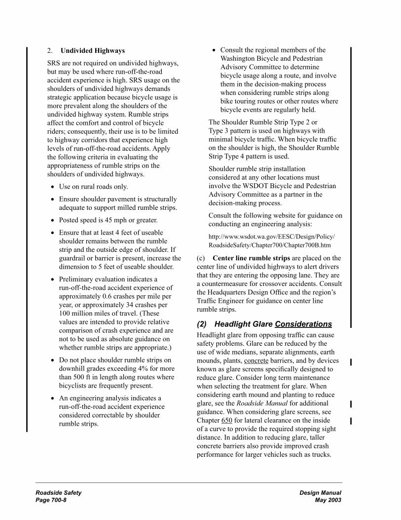
Roadside Safety Design ManualPage 700-8 May 2003
Design Manual Roadside SafetyMay 2003 Page 700-9
2. Undivided Highways
SRS are not required on undivided highways, but may be used where run-off-the-road accident experience is high. SRS usage on the shoulders of undivided highways demands strategic application because bicycle usage is more prevalent along the shoulders of the undivided highway system. Rumble strips affect the comfort and control of bicycle riders; consequently, their use is to be limited to highway corridors that experience high levels of run-off-the-road accidents. Apply the following criteria in evaluating the appropriateness of rumble strips on the shoulders of undivided highways.
• Use on rural roads only.
• Ensure shoulder pavement is structurally adequate to support milled rumble strips.
• Posted speed is 45 mph or greater.
• Ensure that at least 4 feet of useable shoulder remains between the rumble strip and the outside edge of shoulder. If guardrail or barrier is present, increase the dimension to 5 feet of useable shoulder.
• Preliminary evaluation indicates a run-off-the-road accident experience of approximately 0.6 crashes per mile per year, or approximately 34 crashes per 100 million miles of travel. (These values are intended to provide relative comparison of crash experience and are not to be used as absolute guidance on whether rumble strips are appropriate.)
• Do not place shoulder rumble strips on downhill grades exceeding 4% for more than 500 ft in length along routes where bicyclists are frequently present.
• An engineering analysis indicates a run-off-the-road accident experience considered correctable by shoulder rumble strips.
• Consult the regional members of the Washington Bicycle and Pedestrian Advisory Committee to determine bicycle usage along a route, and involve them in the decision-making process when considering rumble strips along bike touring routes or other routes where bicycle events are regularly held.
The Shoulder Rumble Strip Type 2 or Type 3 pattern is used on highways with minimal bicycle traffic. When bicycle traffic on the shoulder is high, the Shoulder Rumble Strip Type 4 pattern is used.
Shoulder rumble strip installation considered at any other locations must involve the WSDOT Bicycle and Pedestrian Advisory Committee as a partner in the decision-making process.
Consult the following website for guidance on conducting an engineering analysis:
http://www.wsdot.wa.gov/EESC/Design/Policy/RoadsideSafety/Chapter700/Chapter700B.htm
(c) Center line rumble strips are placed on the center line of undivided highways to alert drivers that they are entering the opposing lane. They are a countermeasure for crossover accidents. Consult the Headquarters Design Office and the region’s Traffic Engineer for guidance on center line rumble strips.
(2) Headlight Glare ConsiderationsHeadlight glare from opposing traffic can cause safety problems. Glare can be reduced by the use of wide medians, separate alignments, earth mounds, plants, concrete barriers, and by devices known as glare screens specifically designed to reduce glare. Consider long term maintenance when selecting the treatment for glare. When considering earth mound and planting to reduce glare, see the Roadside Manual for additional guidance. When considering glare screens, see Chapter 650 for lateral clearance on the inside of a curve to provide the required stopping sight distance. In addition to reducing glare, taller concrete barriers also provide improved crash performance for larger vehicles such as trucks.
Roadside Safety Design ManualPage 700-8 May 2003
Design Manual Roadside SafetyMay 2003 Page 700-9
Glare screen is relatively expensive and its use must be justified and documented. It is difficult to justify the use of glare screen where the median width exceeds 20 ft, the ADT is less than 20,000 vehicles per day, or the roadway has continuous lighting. Consider the following factors when assessing the need for glare screen:
• Higher rate of night accidents compared to similar locations or statewide experience.
• Higher than normal ratio of night to day accidents.
• Unusual distribution or concentration of nighttime accidents.
• Over representation of older drivers in night accidents.
• Combination of horizontal and vertical alignment, particularly where the roadway on the inside of a curve is higher than the roadway on the outside of the curve.
• Direct observation of glare.
• Public complaints concerning glare.
The most common glare problem is between opposing main line traffic. Other conditions for which glare screen might be appropriate are:
• Between a highway and an adjacent frontage road or parallel highway, especially where opposing headlights might seem to be on the wrong side of the driver.
• At an interchange where an on-ramp merges with a collector distributor and the ramp traffic might be unable to distinguish between collector and main line traffic. In this instance, consider other solutions, such as illumination.
• Where headlight glare is a distraction to adjacent property owners. Playgrounds, ball fields, and parks with frequent nighttime activities might benefit from screening if headlight glare interferes with these activities.
There are currently three basic types of glare screen available: chain link (see Standard Plans), vertical blades, and concrete barrier. (See Figure 700-7.)
When the glare is temporary (due to construction activity), consider traffic volumes, alignment, duration, presence of illumination, and type of construction activity. Glare screen may be used to reduce rubbernecking associated with construction activity, but less expensive methods, such as plywood that seals off the view of the construction area, might be more appropriate.
700.08 DocumentationA list of documents that are required to be preserved in the Design Documentation Package (DDP) or the Project File (PF) is on the following website:http://www.wsdot.wa.gov/eesc/design/projectdev/

Roadside Safety Design ManualPage 700-10 May 2003
Design Manual Roadside SafetyMay 2003 Page 700-11
Design Clear Zone Distances for State Highways Outside Incorporated Cities**(In feet from edge of traveled way***)
Posted Speed mph
Average Daily Traffic
Cut Section (Back Slope) (H:V)
Fill Section (H:V)
3:1 4:1 5:1 6:1 8:1 10:1 3:1 4:1 5:1 6:1 8:1 10:1 35 or Less The Design Clear Zone-distance is 10 feet
40 Under 250 10 10 10 10 10 10 * 13 12 11 11 10251-800 11 11 11 11 11 11 * 14 14 13 12 11
801-2000 12 12 12 12 12 12 * 16 15 14 13 122001-6000 14 14 14 14 14 14 * 17 17 16 15 14Over 6000 15 15 15 15 15 15 * 19 18 17 16 15
45 Under 250 11 11 11 11 11 11 * 16 14 13 12 11251-800 12 12 13 13 13 13 * 18 16 14 14 13
801-2000 13 13 14 14 14 14 * 20 17 16 15 142001-6000 15 15 16 16 16 16 * 22 19 17 17 16Over 6000 16 16 17 17 17 17 * 24 21 19 18 17
50 Under 250 11 12 13 13 13 13 * 19 16 15 13 13251-800 13 14 14 15 15 15 * 22 18 17 15 15
801-2000 14 15 16 17 17 17 * 24 20 18 17 172001-6000 16 17 17 18 18 18 * 27 22 20 18 18Over 6000 17 18 19 20 20 20 * 29 24 22 20 20
55 Under 250 12 14 15 16 16 17 * 25 21 19 17 17251-800 14 16 17 18 18 19 * 28 23 21 20 19
801-2000 15 17 19 20 20 21 * 31 26 23 22 212001-6000 17 19 21 22 22 23 * 34 29 26 24 23Over 6000 18 21 23 24 24 25 * 37 31 28 26 25
60 Under 250 13 16 17 18 19 19 * 30 25 23 21 20251-800 15 18 20 20 21 22 * 34 28 26 23 23
801-2000 17 20 22 22 23 24 * 37 31 28 26 252001-6000 18 22 24 25 26 27 * 41 34 31 29 28Over 6000 20 24 26 27 28 29 * 45 37 34 31 30
65 Under 250 15 18 19 20 21 21 * 33 27 25 23 22251-800 17 20 22 22 24 24 * 38 31 29 26 25
801-2000 19 22 24 25 26 27 * 41 34 31 29 282001-6000 20 25 27 27 29 30 * 46 37 35 32 31Over 6000 22 27 29 30 31 32 * 50 41 38 34 33
70 Under 250 16 19 21 21 23 23 * 36 29 27 25 24251-800 18 22 23 24 26 26 * 41 33 31 28 27
801-2000 20 24 26 27 28 29 * 45 37 34 31 302001-6000 22 27 29 29 31 32 * 50 40 38 34 33Over 6000 24 29 31 32 34 35 * 54 44 41 37 36
* When the fill section slope is steeper than 4H:1V but not steeper than 3H:1V, the Design Clear Zone distance is modified by the recovery area formula (Figure 700-3) and is referred to as the recovery area. The basic philosophy behind the recovery area formula is that a vehicle can traverse these slopes but cannot recover (control steering) and, therefore, the horizontal distance of these slopes is added to the Design Clear Zone distance to form the recovery area.** This figure also applies to limited access state highways in cities and median areas on managed access state highways in cities. See 700.04 for guidance on managed access state highways within incorporated cities.*** See 700.03 for definition of traveled way.
Design Clear Zone Distance Table Figure 700-1

Roadside Safety Design ManualPage 700-10 May 2003
Design Manual Roadside SafetyMay 2003 Page 700-11
Design Clear Zone Inventory FormFigure 700-2a
DO
TFo
rm 4
10-0
26 E
FR
evis
ed 9
/02
Des
ign
Cle
ar Z
one
Inve
ntor
yR
egio
nSR
Con
trol S
ectio
nM
Pto
MP
Proj
ect T
itle
Proj
ect N
umbe
r
Dat
e
Res
pons
ible
Uni
t
Item
Num
ber
MP
to M
PD
ista
nce
From
Trav
eled
Way
Des
crip
tion
Cor
rect
ive
Act
ions
Con
side
red
(2)
Estim
ated
Cos
t to
Cor
rect
Cor
rect
ion
Plan
ned
(1)
Yes
No
LR
(1)
Onl
y on
e �Y
es� o
r �N
o� p
er it
em n
umbe
r. C
orre
ctio
ns n
ot p
lann
ed m
ust b
e ex
plai
ned
on re
vers
e si
de.
(2)
A lis
t of L
ocat
ion
1 &
2 U
tility
Obj
ects
to th
e fo
rwar
ded
to th
e re
gion
Util
ity O
ffice
for c
oord
inat
ion
per C
ontro
l Zon
e G
uide
lines
.

Roadside Safety Design ManualPage 700-12 May 2003
Design Manual Roadside SafetyMay 2003 Page 700-13
Design Clear Zone Inventory FormFigure 700-2b
Item
Num
ber
Rea
sons
for N
ot T
akin
g C
orre
ctiv
e A
ctio
n
DO
TFo
rm 4
10-0
26 E
FR
evis
ed 9
/02

Roadside Safety Design ManualPage 700-12 May 2003
Design Manual Roadside SafetyMay 2003 Page 700-13
Recovery AreaFigure 700-3
*Recovery area normally applies to slopes steeper than 4H:1V but no steeper than 3H:1V. For steeper slopes, the recovery area formula may be used as a guide if the embankment height is 10 ft or less.
Formula:
Recovery area = (shoulder width) + (horizontal distance)
+ (Design Clear Zone distance - shoulder width)
Example:
Fill section (slope 3H:1V or steeper)
Conditions: Speed - 45 mph
Traffic - 3000 ADT
Slope - 3H:1V
Criteria: Slope 3H:1V - use
Recovery area formula
Recovery area = (shoulder width) + (horizontal distance)+ (Design Clear Zone distance - shoulder width)
= 8 + 12 + (17 - 8)
= 29 ft

Roadside Safety Design ManualPage 700-14 May 2003
Design Manual Roadside SafetyMay 2003 Page 700-15
Cut section with ditch (foreslope 4H:1V or flatter)
Conditions: Speed - 55 mph
Traffic - 4200 ADT
Slope - 4H:1V
Criteria: Greater of
(1) Design Clear Zone for 10H:1V Cut Section, 23 ft
(2) 5 ft horizontal beyond beginning of back slope, 22 ft
Design Clear Zone = 23 ft
Case 1Cut section with ditch (foreslope 3H:1V or steeper and back slope steeper than 3H:1V)
Conditions: NA
Criteria: 10 ft horizontal beyond beginning of back slope
Design Clear Zone = 19 ft
Case 2Cut section with ditch (foreslope 3H:1V or steeper and back slope not steeper than 3H:1V)
Conditions: Speed - 45 mph
Traffic - 3000 ADT
Foreslope - 2H:1V
Back slope 4H:1V
Criteria: Use recovery area formula
Recovery Area = (shoulder width) + (horizontal distance) + (Design Clear Zone distance - shoulder width)
= 6 + 6 + (15 - 6)
= 21 ft
Case 3
Design Clear Zone for Ditch SectionsFigure 700-4
Roadside Safety Design ManualPage 700-16 Draft DMcC 11/14/02
Cut section with ditch (fore slope 4H:1V or flatter)
Conditions: Speed - 55 mph
Traffic - 4200 ADT
Slope - 4H:1V
Criteria: Greater of
(1) Design Clear Zone for 10H:1V Cut Section, 23 ft
(2) 5 ft horizontal beyond beginning of back slope, 22 ft
Design Clear Zone = 23 ft
Case 1 Cut section with ditch (fore slope 3H:1V or steeper and back slope steeper than 3H:1V)
Conditions: NA
Criteria: 10 ft horizontal beyond beginning of back slope
Design Clear Zone = 19 ft
Case 2 Cut section with ditch (fore slope 3H:1V or steeper and back slope not steeper than 3H:1V)
Conditions: Speed - 45 mph
Traffic - 3000 ADT
Foreslope - 2H:1V
Back slope 4H:1V
Criteria: Use recovery area formula
Recovery Area = (shoulder width) + (horizontal distance) + (Design Clear Zone distance - shoulder width)
= 6 + 6 + (15 - 6)
= 21 ft
Case 3
Design Clear Zone for Ditch Sections Figure 700-4
Design Clear Zone = 23 ft
Edge oftraveled way
4H:1V 3H:1V
8 ft6 ftshld 3 ft
Design Clear Zone = 19 ft
Edge oftraveled w ay
3H:1V 2H:1V
10 ft6 ft3 ftshld
Recovery Area = 21 ft
Edge oftraveled way
2H:1V 4H:1V
6 ft6 ftshld

Roadside Safety Design ManualPage 700-14 May 2003
Design Manual Roadside SafetyMay 2003 Page 700-15
Guidelines for Embankment BarrierFigure 700-5

Roadside Safety Design ManualPage 700-16 May 2003
Design Manual Roadside SafetyMay 2003 Page 700-17
Mailbox Location and Turnout DesignFigure 700-6

Roadside Safety Design ManualPage 700-16 May 2003
Design Manual Roadside SafetyMay 2003 Page 700-17
Glare ScreensFigure 700-7
Glare ScreensFigure 700-8
Roadside Safety Design ManualPage 700-16 English Version August 1997
Chain Link
Vertical Blades Concrete Barrier


Design Manual High Occupancy Vehicle FacilitiesMay 2003 Page 1050-1
1050.01 General1050.02 References1050.03 Definitions1050.04 Preliminary Design and Planning1050.05 Operations1050.06 Design Criteria1050.07 Documentation
1050.01 GeneralHigh occupancy vehicle (HOV) facilities include separate HOV roadways, HOV lanes, transit lanes, HOV direct access ramps, and flyer stops. The objectives for the HOV facilities are:
• Improve the capability of corridors to move more people by increasing the number of people per vehicle.
• Provide travel time savings and a more reliable trip time to HOV lane users.
• Provide safe travel options for HOVs without adversely affecting the safety of the general-purpose lanes.
Plan, design, and construct HOV facilities that ensure intermodal linkages. Give consideration to future highway system capacity needs. Whenever possible, design HOV lanes so that the level of service for the general-purpose lanes will not be degraded.
In urban corridors that do not currently have planned or existing HOV lanes, complete an analysis of the need for HOV lanes before proceeding with any projects for additional general-purpose lanes. In corridors where both HOV and general-purpose facilities are planned, construct the HOV lane before or simultaneously with the construction of new general-purpose lanes.
See the following chapters for additional information:
Chapter Subject
430 general-purpose roadway widths for modified design level
440 general-purpose roadway widths for full design level
640 general-purpose turning roadway widths and other cross section data
1050.02 ReferencesRevised Code of Washington (RCW) 46.61.165, High-occupancy vehicle lanes
RCW 47.52.025, Additional powers — Controlling use of limited access facilities —High-occupancy vehicle lanes
Washington Administrative Code (WAC) 468-510-010, High occupancy vehicles (HOVs)
Standard Plans for Road, Bridge, and Municipal Construction (Standard Plans), M 21-01, Washington State Department of Transportation (WSDOT)
HOV Direct Access Design Guide, Draft, M 22-98, WSDOT
Manual on Uniform Traffic Control Devices for Streets and Highways (MUTCD), 2000, U.S. Department of Transportation, Federal Highway Administration; including the Washington State Modifications to the MUTCD, M 24-01, WSDOT
Traffic Manual, M 51-02, WSDOT
Guide for the Design of High Occupancy Vehicle Facilities, American Association of State Highway and Transportation Officials (AASHTO)
Design Features of High Occupancy Vehicle Lanes, Institute of Traffic Engineers (ITE)
High-Occupancy Vehicle Facilities: Parsons Brinkerhoff, Inc.
NCHRP Report 414, HOV Systems Manual
1050.03 Definitionsbuffer-separated HOV lane An HOV lane that is separated from the adjacent same direction general-purpose freeway lanes by a designated buffer.
Chapter 1050 High Occupancy Vehicle Facilities

High Occupancy Vehicle Facilities Design ManualPage 1050-2 May 2003
Design Manual High Occupancy Vehicle FacilitiesMay 2003 Page 1050-3
bus rapid transit (BRT) An express rubber tired transit system operating predominantly in roadway managed lanes. It is generally characterized by separate roadway or buffer-separated HOV lanes, HOV direct access ramps, and a high occupancy designation (3+ or higher).
business access transit (BAT) lanes A transit lane that allows use by other vehicles to access abutting businesses.
enforcement area A place where vehicles may be stopped for ticketing by law enforcement. It also may be used as an observation point and for emergency refuge.
enforcement observation point A place where a law enforcement officer may park and observe traffic.
flyer stop A transit stop inside the limited access boundaries.
high occupancy toll (HOT) lane A managed lane that combines a high occupancy vehicle lane and a toll lane.
high occupancy vehicle (HOV) A vehicle that fits one of the following:
(1) Rubber tired municipal transit vehicles.
(2) Buses with a carrying capacity of sixteen or more persons, including the operator.
(3) Motorcycles.
(4) Recreational vehicles that meet the occupancy requirements of the facility.
(5) All other vehicles that meet the occupancy requirements of the facility, except trucks in excess of 10,000 lb gross vehicle weight.
HOV direct access ramp An on or off ramp exclusively for the use of HOVs that provides access between a freeway HOV lane and a street, transit support facility, or another freeway HOV lane without weaving across general-purpose lanes.
HOV facility A priority treatment for HOVs.
level of service A qualitative measure describing operational conditions within a traffic stream, incorporating factors of speed and travel time, freedom to maneuver, traffic interruptions, comfort and convenience, and safety.
managed lane A lane that increases efficiency by packaging various operational and design actions. Lane management operations may be adjusted at any time to better match regional goals.
nonseparated HOV lane An HOV lane that is adjacent to and operates in the same direction as the general-purpose lanes with unrestricted access between the HOV lane and the general-purpose lanes.
occupancy designation The minimum number of occupants required for a vehicle to use the HOV facility.
separated HOV facility An HOV roadway that is physically separated from adjacent general-purpose lanes by a barrier, median, or on a separate right of way.
single occupant vehicle (SOV) Any motor vehicle other than a motorcycle carrying one occupant.
transit lane A lane for the exclusive use of transit vehicles.
violation rate The total number of violators divided by the total number of vehicles on an HOV facility.
1050.04 Preliminary Design and Planning(1) Planning Elements for DesignIn order to determine the appropriate design options for an HOV facility, the travel demand and capacity must first be established; identify suitable corridors, evaluate the HOV facility location and length, and estimate the HOV demand. A viable HOV facility will satisfy the following criteria:
• Be part of an overall transportation plan.
• Have the support of the community and public.
High Occupancy Vehicle Facilities Design ManualPage 1050-2 May 2003
Design Manual High Occupancy Vehicle FacilitiesMay 2003 Page 1050-3
• Respond to demonstrated congestion or near-term anticipated congestion: Level of Service E or F for at least one hour of peak period (traffic approaching a capacity of 1,700 to 2,000 vehicles per hour per lane) or average speeds less than 30 mph during peak periods over an extended distance.
• Except for a bypass of a local bottleneck, be of sufficient length to provide a travel time saving of at least 5 minutes during the peak periods.
• Have sufficient numbers of HOV users for a cost-effective facility and to avoid the per-ception of under utilization. (HOV volumes of 400 to 500 vehicles per hour on nonseparated lanes and 600 to 800 on separated facilities.)
• Provide a safe, efficient, and enforceable operation.
A queue or bottleneck bypass can be effective without satisfying all of the above. An isolated bypass can be viable when there is localized, recurring traffic congestion, and such treatment will provide a travel time saving to an adequate number of HOV users.
The efficiency of the HOV facility can be affected by the access provisions. Direct access between park and ride/transit facilities and an HOV lane is the most desirable, but it is also an expensive alternative. Direct access options are discussed in the HOV Direct Access Design Guide.
Document the need for the HOV lane and how the proposed lane will meet those needs.
(2) HOV Facility TypeMake a determination as to the type of HOV lane. The three major choices are separated roadway, buffer-separated lane, and nonseparated HOV lane.
(a) Separated Roadway. The separated roadway can be either a one-way reversible or a two-way operation. The directional split in the peak periods, space available, and operating logistics are factors to be considered. A separated HOV roadway may be located in the median of the freeway, next to the freeway, or on an independent alignment. Separated HOV facilities are more effective for:
• Large HOV volumes.
• Large merging and weaving volumes.
• Long-distance HOV travel.
Reversible, separated roadways operate effectively where there are major directional splits during peak periods. Consider potential changes in this traffic pattern and designing the facility to accommodate possible conversion to two-way operation. The separated roadway is normally more efficient, provides for the higher level of safety, and is more easily enforced. However, it is generally the most expensive type of HOV facility to implement.
(b) Buffer-Separated. A buffer-separated HOV lane is similar to a freeway nonseparated HOV lane on the left, but with a buffer between the HOV lane and the general-purpose lanes. The addition of a buffer provides better delineation between the lanes and controls access between the HOV lane and general-purpose lanes to improve operation.
(c) Nonseparated. Nonseparated HOV lanes operate in the same direction and immediately adjacent to the general-purpose lanes. They are located either to the left (preferred) or to the right of the general-purpose lanes. Nonseparated HOV lanes are normally cheaper, easier to implement, and provide more opportunity for frequent access. However, the ease of access can create more problems for enforcement and a higher potential for conflicts.
(3) Freeway Operational AlternativesFor an HOV lane on a limited access facility, consider the following operational alternatives:
• Inside (preferred) or outside HOV lane.
• Lane conversion.
• Use of existing shoulder (not recommended for permanent operations).
• HOV direct access ramps.
• Queue bypasses.
• Flyer stops.
• Hours of operation.

High Occupancy Vehicle Facilities Design ManualPage 1050-4 May 2003
Design Manual High Occupancy Vehicle FacilitiesMay 2003 Page 1050-5
When evaluating alternatives, consider a combination of alternatives to provide the best solution for the corridor. Also, incorporate flexibility into the design in order not to preclude potential changes in operation, such as outside-to-inside lane and reversible to two-way operations. Access, freeway-to-freeway connections, and enforcement will have to be accommodated for such changes. Document the operational alternatives.
(a) Inside Versus Outside HOV Lane. System continuity and consistency of HOV lane placement along a corridor are important and influence facility development decisions. Other issues include land use, trip patterns, transit vehicle service, HOV volume, ramp volume, congestion levels, safety, enforcement, and direct access to facilities.
The inside (left) HOV lane is most appropriate for a corridor with long distance trip patterns, such as a freeway providing mobility to and from a large activity center. These trips are characterized by long distance commuters and express transit service. Maximum capacity for an effective inside HOV lane is approximately 1,500 vehicles per hour. When the HOVs weaving across the general-purpose lanes cause severe congestion, consider implementing HOV direct access ramps, separated HOV roadways, or a higher occupancy designation. Inside lanes are preferred for HOV lanes on freeways.
The outside (right) HOV lane is most appropriate for a corridor with shorter, widely dispersed trip patterns. These trip patterns are characterized by transit vehicle routes that exit and enter at nearly every interchange. The maximum capacity for an effective outside HOV lane is reduced and potential conflicts are increased by heavy main line congestion and large entering and exiting general-purpose volumes.
(b) Conversion of a General-Purpose Lane. The use of an existing general-purpose lane for an HOV lane is not a preferred option; however, conversion of a lane to an HOV lane might be justified when the conversion provides greater people-moving capability on the roadway. Use of an existing freeway lane as an HOV lane will be considered only with a deviation.
Given sufficient existing capacity, converting a general-purpose lane to an HOV lane will provide for greater people moving capability in the future without significantly affecting the existing roadway operations. The fastest and least expensive method for providing an HOV lane is through conversion of a general-purpose lane. Restriping and signing are sometimes all that is needed. Converting a general-purpose lane to HOV use will likely have environmental benefits. This method, however, is controversial from a public acceptance standpoint. Public support might be gained through an effective public involvement program. See Chapter 210, Public Involvement and Hearings.
Lane conversion of a general-purpose lane to an HOV lane must enhance the corridor’s people moving capacity. It is critical that an analysis be conducted that includes:
• Public acceptance of the lane conversion.
• Present and long-term traffic impacts on the adjacent general-purpose lanes and the HOV lane.
• Impacts to the neighboring streets and arterials.
• Legal, environmental, and safety impacts.
(c) Use of Existing Shoulder. When considering the alternatives in order to provide additional width for an HOV lane, the use of the existing shoulder is not a preferred option. Use of the shoulder on a freeway or freeway ramp as an HOV lane will be considered only with a deviation.
Consider shoulder conversion to an HOV lane when traffic volumes are heavy and the conversion is a temporary measure. Another alternative is to use the shoulder as a permanent measure to serve as a transit-only or queue bypass lane during peak hours and then revert to a shoulder in off peak hours. The use of the shoulder creates special signing, operational, and enforcement problems. An agreement is required with the transit agency to ensure that transit vehicles will only use the shoulder during peak hours. The use of the shoulder must be clearly defined by signs. Institute special operations to ensure the shoulder is clear and available for the designated hours.

High Occupancy Vehicle Facilities Design ManualPage 1050-4 May 2003
Design Manual High Occupancy Vehicle FacilitiesMay 2003 Page 1050-5
The existing shoulder pavement is often not designed to carry heavy volumes of vehicles, especially transit vehicles. As a result, repaving and reconstruction of the shoulder might be required.
(d) HOV Direct Access Ramps. To improve the efficiency of an HOV system, exclusive HOV access connections for an inside HOV lane may be considered. See the HOV Direct Access Design Guide for information on HOV direct access connections. Direct access reduces the need for HOVs to cross the general-purpose lanes from right side ramps. Transit vehicles will be able to use the HOV lane and provide service to park and ride lots, flyer stops, or other transit stops by the HOV direct access ramps.
(e) Queue Bypass Lanes. A queue bypass lane allows HOVs to save time by avoiding congestion at an isolated bottleneck. An acceptable time saving for a queue bypass is one minute or more. Typical locations for queue bypasses are at ramp meters, signalized intersections, toll plaza or ferry approaches, and locations with isolated main line congestion. By far the most common use is with ramp metering. Queue bypass lanes can be built along with a corridor HOV facility or indepen-dently. In most cases, they are relatively low cost and easily implemented. Where practical, include HOV bypasses on ramp metering sites or make provisions for their future accommodation, unless specific location conditions dictate otherwise.
(f) Flyer Stops. Flyer stops reduce the time required for express transit vehicles to serve intermediate destinations. However, passengers must travel greater distances to reach the loading platform. For information on flyer stops, see the HOV Direct Access Design Guide.
(g) Hours of Operation. HOV designation on freeway HOV lanes 24 hours a day provides benefits to users during off peak periods, minimizes potential confusion, makes enforcement easier, and simplifies signing and striping. However, 24-hour operation also might result in a lane not used during off peak periods, negative public opinion, and the need for full time enforcement.
(4) Arterial Street Operational AlternativesArterial street HOV lanes also have a variety of HOV alternatives to be considered. Some of these alternatives are site specific or have limited applications. Arterial HOV lanes differ from freeway HOV lanes in slower speeds, little access control (turning traffic can result in right angle conflicts), and traffic signals. Arterial HOV lanes are occasionally designated for transit vehicles only, especially in cities with a large concentration of transit vehicles. When evaluating alternatives consider traffic signal queues and managed access highway class. The alternatives include:
• Type of lane.
• Left side or right side HOV lane.
• Hours of operation.
• Spot treatments.
• Bus stops.
When evaluating alternatives, consider a combination of alternatives to provide the best solution for the corridor. Also, incorporate flexibility into the design in order not to preclude potential changes in operation. Document the operational alternatives.
(a) Type of lane. Lanes can be transit only or include all HOVs. Transit only lanes are desirable where bus volumes are high with a high level of congestion. They will increase the speed of transit vehicles through congested areas and improve the reliability of the transit service. Lanes that allow use by all HOVs are appropriate on corridors with high volumes of carpools and vanpools. They can collect carpools and vanpools in business and industrial areas and connect them to the freeway system.
(b) Left side or right side HOV lane. Continuity of HOV lane location along a corridor is an important consideration when making the decision whether to locate an arterial street HOV lane on the left or right side of the street. Other issues include land use, trip patterns, transit vehicle service, safety, enforcement, and presence of parking.

High Occupancy Vehicle Facilities Design ManualPage 1050-6 May 2003
Design Manual High Occupancy Vehicle FacilitiesMay 2003 Page 1050-7
The right side is the preferred location for arterial street HOV lanes on transit routes with frequent stops. It is the most convenient for passenger boarding at transit stops. It is also the most common location for HOV lanes on arterial streets. General-purpose traffic must cross the HOV lane to make a right-turn at intersections and to access driveways. These turns across the HOV lane can create conflicts. Minimizing access points that create these conflict locations is recommended. Other issues to consider are on street parking, stopping area for delivery vehicles, and enforcement areas.
Left side arterial street HOV lanes are less common than right side lanes. HOV lanes on the left eliminate the potential conflicts with driveway access, on street parking, and stopping area for delivery vehicles. The result is fewer delays and higher speeds making left side arterial street HOV lanes appropriate for longer distance trips. Disadvantages are the difficulty providing transit stops and the need to provide for left turning general-purpose traffic.
(c) Hours of operation. An arterial street HOV lane can either operate as an HOV lane 24 hours a day or during peak hours only. Factors to consider in determining which to use include type of HOV lane, level of congestion, continuity, and enforcement.
HOV lanes operating 24 hours a day are desirable when congestion and HOV demand exists for extended periods throughout the day. The 24 hour operation provides benefits to users during off peak periods, minimizes potential confusion, makes enforcement easier, and simplifies signing and striping. Disadvantages are negative public opinion if the lane is not used during off peak periods, the need for full time enforcement, and the loss of on street parking.
Peak period HOV lanes are appropriate for arterial streets with HOV demand or congestion existing mainly during the peak period. Peak period HOV lanes provide HOV priority at the critical times of the day, lessen the negative public perception of the HOV lane, and allow on street parking or other shoulder uses at other times. The disadvantages include possible confusion to the drivers, more difficult enforcement, increased
signing, and the need to institute special operations to ensure the shoulder or lane is clear and available for the designated period.
(d) Spot Treatments. A spot HOV treatment is used to give HOVs priority around a bottleneck. It can provide time savings, travel time reliability, and improve access to other facilities. Examples include a short HOV lane to provide access to a freeway on-ramp, one lane of a dual turn-lane, a priority lane at ferry terminals, and priority at traffic signals.
Signal priority treatments that alter the sequence or duration of a traffic signal are techniques for providing preferential treatment for transit vehicles. The priority treatments can range from timing and phasing adjustments to signal preemption. Consider the overall impact on traffic. Preemption would normally not be an appropriate treatment where traffic signal timing and coordination are being utilized or where there are high volumes on the cross streets.
(e) Bus stops. Normally, with arterial HOV lanes, there is not a shoulder suitable for a bus to use while stopped to load and unload passengers without blocking the lane. Therefore, bus stops are either in-lane or in a pullout. In-lane bus stops are the simplest type of bus stop. However, stopped buses will block the HOV lane; therefore, in-lane bus stops are only allowed in transit lanes. Bus pullouts provide an area for buses to stop without blocking the HOV lane. Disadvantages include higher cost, reduced width for the sidewalk or other roadside area, and possible difficulty reentering the HOV lane. See Chapter 1060 for additional information on bus stop location and design.
1050.05 Operations(1) Vehicle Occupancy DesignationSelect the vehicle occupancy designation to provide the maximum movement of people in a corridor, provide free-flow HOV operations, reduce the empty lane perception, provide for the ability to accommodate future HOV growth within a corridor, and be consistent with the regional transportation plan and the policies adopted by the metropolitan planning organization (MPO).
High Occupancy Vehicle Facilities Design ManualPage 1050-6 May 2003
Design Manual High Occupancy Vehicle FacilitiesMay 2003 Page 1050-7
An initial occupancy designation must be established. It is WSDOT policy to use the 2+ designation as the initial occupancy designation. Consider a 3+ occupancy designation if it is anticipated during initial operation that the volumes will be 1,500 vehicles per hour for a left-side HOV lane, or 1,200 vehicles per hour for a right-side HOV lane, or that a 45 mph operating speed cannot be maintained for more than 90 percent of the peak hour.
(2) EnforcementEnforcement is necessary for the success of an HOV facility. Coordination with the Washington State Patrol (WSP) is critical when the operational characteristics and design alternatives are being established. This involvement ensures that the project is enforceable and will receive their support.
Provide both enforcement areas and observation points for all high-speed HOV lanes and ramp facilities.
Barrier-separated facilities, because of the limited access, are the easiest facilities to enforce. Shoulders provided to accommodate breakdowns may also be used for enforcement. Reversible facilities have ramps for the reverse direction that may be used for enforcement. Gaps in the barrier may be needed so emergency vehicles can access barrier-separated HOV lanes.
Buffer-separated and nonseparated HOV lanes allow violators to easily enter and exit the HOV lane. For this reason, providing strategically located enforcement areas and observation points is essential.
Consider the impact on safety and visibility for the overall facility during the planning and design of enforcement areas and observation points. Where HOV facilities do not have enforcement areas, or where officers perceive that the enforcement areas are inadequate, enforcement on the facility will be difficult and less effective.
(3) Intelligent Transportation SystemsThe objective of intelligent transportation systems (ITS) is to make more efficient use of our transportation network. This is done by collecting data, managing traffic, and relaying information to the motoring public.
It is important that an ITS system is incorporated into the HOV project and that the HOV facility fully utilize the ITS features available. This includes providing a strategy of incident management since vehicle breakdowns and accidents have a significant impact on the efficient operation of the HOV facilities. See Chapter 860 for more information on ITS.
1050.06 Design Criteria(1) Design ProceduresSee the design matrices (Chapter 325) for the required design level for the elements of an HOV project.
(2) Design ConsiderationsHOV lanes are designed to the same criteria as the facilities they are attached. Design nonseparated and buffer-separated HOV lanes to match the vertical alignment, horizontal alignment, and cross slope of the adjacent lane. A deviation is required when any proposed or existing design element does not meet the applicable design level for the project.
(3) Adding an HOV LaneThe options for adding an HOV lane are reconstruction, restriping, combined reconstruction and restriping, and possibly lane conversion.
Reconstruction involves creating roadway width. Additional right of way may be required. Restriping involves reallocating the existing paved roadway to create enough space to provide an additional HOV lane. Restriping of lane or shoulder widths to less than for the design level and functional class of the highway is a design deviation and approval is required.

High Occupancy Vehicle Facilities Design ManualPage 1050-8 May 2003
Design Manual High Occupancy Vehicle FacilitiesMay 2003 Page 1050-9
Reconstruction and restriping can be combined to maximize use of the available right of way. For example, a new lane can be created through a combination of median reconstruction, shoulder reconstruction, and lane restriping. Each project will be handled on a case by case basis. Generally consider the following reductions in order of preference:
(a) Reduction of the inside shoulder width, pro-vided the enforcement and safety mitigation issues are addressed. (Give consideration not to preclude future HOV direct access ramps by over reduction of the available median width.)
(b) Reduction of the interior general-purpose lane width to 11 ft.
(c) Reduction of the outside general-purpose lane width to 11 ft.
(d) Reduction of the HOV lane to 11 ft.
(e) Reduction of the outside shoulder width to 8 ft.
If lane width adjustments are necessary, old lane markings must be thoroughly eradicated. It is desirable that longitudinal joints (new or existing) not conflict with tire track lines. If they do, consider overlaying the roadway before restriping.
(4) Design Criteria for Types of HOV Facilities(a) Separated Roadway HOV Facilities. The separated HOV facility can be single lane or multilane and directional or reversible. (See Figure 1050-2.)
1. Lane Widths. See Figure 1050-1 for traveled way width (WR) on turning roadways.
2. Shoulder Widths. The shoulder width requirements are as follows:
• The minimum width for the sum ofthe two shoulders is 12 ft for one-lane facilities and 14 ft for two-lane facilities.
• One of the shoulders must have a width of at least 10 ft for disabled vehicles. The minimum for the other shoulder is 2 ft for one-lane facilities and 4 ft for two-lane facilities.
• The wider shoulder may be on the left or the right as needed to best match the conditions. Maintain the wide shoulder on the same side throughout the facility.
3. Total Widths. To reduce the probability of blocking the HOV facility, make the total width (lane width plus paved shoulders) wide enough to allow an A-BUS to pass a stalled A-BUS. For single lane facilities, the traveled way widths (WR), given in Figure 1050-1, plus the 12 ft total shoulder width will provide for this passing for radii (R) 100 ft or greater. For R of 75 ft, a total roadway width of 33 ft is needed and for R of 50 ft, a total roadway width of 41 ft is needed to provide for the passing.
R (ft)(1) WR (ft)1-Lane 2-Lane
3001 to Tangent 13(2) 243000 14 242000 14 251000 15 26500 15 27300 15 28200 16 29150 17 31100 18 3475 19 3750 22 45
(1) Radius (R) is on the outside edge of traveled way on 1-lane and center line on 2-lane roadways.
(2) May be reduced to 12 ft on tangent.
Minimum Traveled Way Widths for Articulated Buses
Figure 1050-1
High Occupancy Vehicle Facilities Design ManualPage 1050-8 May 2003
Design Manual High Occupancy Vehicle FacilitiesMay 2003 Page 1050-9
(b) Nonseparated Freeway HOV Lanes. For both inside and outside HOV lanes, the minimum lane width is 12 ft and the minimum shoulder width is 10 ft. (See Figure 1050-2.)
When a left shoulder less than 10 ft wide is proposed for distances exceeding 1.5 mi, enforcement and observation areas must be provided at 1- to 2-mi intervals. See 1050.06(7).
Where left shoulders less than 8 ft wide are proposed for lengths of roadway exceeding 0.5 mi, safety refuge areas must be provided at 0.5- to 1-mi intervals. These can be in addition to or in conjunction with the enforcement areas.
Allow general-purpose traffic to cross HOV lanes at on-and off-ramps.
(c) Buffer-Separated HOV lanes. Design buffer-separated HOV lanes the same as for inside nonseparated HOV lanes, except for a buffer 2 to 4 ft in width or 10 ft or greater in width with pavement marking, with supplemental signing, to restrict crossing. For buffer-separated HOV lanes with a buffer at least 4 ft wide, the left shoulder may be reduced to 8 ft. Buffer widths between 4 and 10 ft are not desirable since they may be used as a refuge area for which the width is not adequate. Provide gaps in the buffer to allow access to the HOV lane.
(d) Arterial Street HOV Lanes. The minimum width for an arterial street HOV lane is 12 ft. Allow general-purpose traffic to cross the HOV lanes to turn at intersections and to access driveways. (See Figure 1050-2.)
For right side HOV lanes adjacent to curbs, provide a 4 ft shoulder between the HOV lane and the face of curb. The shoulder may be reduced to 2 ft with justification.
For HOV lanes on the left, a 1 ft left shoulder between the HOV lane and the face of curb is required. When concrete barrier is adjacent to the HOV lane, the minimum shoulder is 2 ft.
(e) HOV Ramp Meter Bypass. The HOV bypass may be created by widening an existing ramp, construction of a new ramp where right of way is available, or reallocation of the existing pavement width provided the shoulders are full depth.
Ramp meter bypass lanes may be located on the left or right of metered lanes. Typically, bypass lanes are located on the left side of the ramp. Consult with local transit agencies and the region’s Traffic Office for direction on which side to place the HOV bypass.
Consider the existing conditions at each location when designing a ramp meter bypass. Design a single lane ramp with a single metered lane and an HOV bypass as shown on Figure 1050-4a. Make the total width of the metered and bypass lanes equal to a 2-lane ramp (Chapters 640 and 940). Design a ramp with two metered lanes and an HOV bypass as shown on Figure 1050-4b. Make the width of the two metered lanes equal to a 2-lane ramp (Chapters 640 and 940) and the width of the bypass lane as shown on Figure 1050-3. The design shown on Figure 1050-4b requires that the ramp operate as a single lane ramp when the meter is not in operation.
Both Figures 1050-4a and 4b show an observation point/enforcement area. Document any other enforcement area design as a design exception. One alternative (a design exception) is to provide a 10-ft outside shoulder from the stop bar to the main line.
(5) HOV Direct Access RampsHOV direct access ramps provide access between an HOV lane and another freeway, a local arterial street, a flyer stop, or a park and ride facility. Design HOV direct access ramps in accordance with the HOV Direct Access Design Guide.
(6) HOV Lane TerminationLocate the beginning and end of an HOV lane at logical points. Provide decision sight distance, signing, and pavement markings at the termination points.
The preferred method of terminating an inside HOV lane is to provide a straight through move for the HOV traffic, ending the HOV restriction and dropping a general-purpose lane on the right. However, analyze volumes for both the HOV lanes and general-purpose lanes, and the geometric conditions, to optimize the overall operational performance of the facility.

High Occupancy Vehicle Facilities Design ManualPage 1050-10 May 2003
Design Manual High Occupancy Vehicle FacilitiesMay 2003 Page 1050-11
(7) Enforcement AreasEnforcement of the inside HOV lane can be done with a minimum 10 ft inside shoulder. For continuous lengths of barrier exceeding 2 mi, a 12 ft shoulder, for the whole length of the barrier, is recommended.
For inside shoulders less than 10 ft, locate enforcement and observation areas at 1- to 2-mi intervals or based on the recommendations of the WSP. These areas can also serve as safety refuge areas for disabled vehicles. See Figures 1050-5a and 5b.
Provide observation points approximately 1300 ft before enforcement areas. They can be designed to serve both patrol cars and motorcycles or motorcycles only. Coordinate with the WSP during the design stage to provide effective placement and to ensure utilization of the observation points. Median openings give motorcycle officers the added advantage of being able to quickly respond to emergencies in the opposing lanes. (See Figure 1050-5b.) The ideal observation point places the motorcycle officer 3 ft above the HOV lane and outside the shoulder so the officer can look down into a vehicle.
Locate the enforcement area on the right side for queue bypasses and downstream from the stop bar so the officer can be an effective deterrent (Figures 1050-4a and 4b).
An optional signal status indicator for enforcement may be placed at HOV lane installations that are metered. The indicator faces the enforcement area so that a WSP officer can determine if vehicles are violating the ramp meter. The indicator allows the WSP officer to simultaneously enforce two areas, the ramp meter and the HOV lane. Consult with the WSP for use at all locations.
See the Traffic Manual regarding HOV metered bypasses for additional information on enforcement signal heads.
(8) Signs and Pavement Markings(a) Signs. Provide post-mounted HOV preferential lane signs next to the HOV lane or overhead mounted over the HOV lane. Make the sign wording clear and precise, stating which lane is restricted, the type of HOVs allowed, and the HOV vehicle occupancy designation for that section of road. The sign size, location, and spacing are dependent upon the conditions under which the sign is used. Roadside signs can also be used to convey other HOV information such as the HERO program, carpool information telephone numbers, and violation fines. Some situations may call for the use of variable message signs.
Place overhead signs directly over the HOV lane to provide maximum visibility. Use a sequence of overhead signs at the beginning and end of all freeway HOV facilities. Overhead signs can also be used in conjunction with roadside signs along the roadway.
(b) Pavement Markings. Provide pavement markings that conform to the Traffic Manual and the Standard Plans.
(c) Interchanges. In the vicinity of interchange on and off connections where merging or exiting traffic crosses an HOV lane, make provisions for general-purpose traffic using the HOV lane. These provisions include signing and striping that clearly show the changes in HOV versus general traffic restrictions. See the Standard Plans for pavement markings and signing.
1050.07 DocumentationA list of the documents that are to be preserved [in the Design Documentation Package (DDP) or the Project File (PF)] is on the following web site: http//www.wsdot.wa.gov/eesc/design/projectdev/

High Occupancy Vehicle Facilities Design ManualPage 1050-10 May 2003
Design Manual High Occupancy Vehicle FacilitiesMay 2003 Page 1050-11
Notes:
(1) The sum of the two shoulders is 12 ft for one-lane and 14 ft for two-lane facilities. One of the shoulders must have a width of at least 10 ft for disabled vehicles. The wider shoulder may be on the left or the right as needed to best match the conditions. Maintain the wide shoulder on the same side throughout the facility. See 1050.06(4)(a)2.
(2) 12 ft minimum for single lane, 24 ft mini-mum for two lanes. Wider width is required on curves. See 1050.06(4)(a)1. and Figure 1050-1.
(3) For total width requirements see 1050.06(4)(a)3.
(4) Width as required for the design level, functional class, and the number of lanes.
(5) Buffer 2 to 4 ft or 10 ft or more.
(6) When buffer width is 4 ft or more, may be reduced to 8 ft.
(7) 2 ft when adjacent to concrete barrier.
(8) Arterial HOV lanes on the left operate in the same direction as the adjacent general-purpose lane.
(9) May be reduced to 2 ft with justification.
Typical HOV Lane SectionsFigure 1050-2
Separated Roadway
(1) (2) (1)
(3)
Nonseparated
10 ' 12' (4)
Buffer-Separated
10' (6) 12' (4)(5)
4' (9)12'12' (8)
1' (7)(4)
Arterial HOV

High Occupancy Vehicle Facilities Design ManualPage 1050-12 May 2003
Design Manual High Occupancy Vehicle FacilitiesMay 2003 Page 1050-13
Radius of Two-Lane Ramp
R (ft)
Design Width of Third Lane(1)
W (ft)
1000 to Tangent 12999 to 500 13499 to 250 14249 to 200 15199 to 150 16149 to 100 17
Notes:
(1) Apply additional width to 2-lane ramp widths.
(2) See traveled way width for two-lane one-way turning roadways in Chapter 640 for turning roadway widths.
Roadway Widths for Two-Lane Ramps with an HOV LaneFigure 1050-3

High Occupancy Vehicle Facilities Design ManualPage 1050-12 May 2003
Design Manual High Occupancy Vehicle FacilitiesMay 2003 Page 1050-13
Single-Lane Ramp Meter With HOV BypassFigure 1050-4a
Notes:
(1) See Standard Plans for striping details.
(2) See Chapter 940 for on-connection details and for acceleration lane length.
(3) See Chapters 940 & 640 for ramp lane and shoulder widths for a 2-lane ramp.
(4) A transition curve with a minimum radius of 3,000 ft is desirable. The minimum length is 300 ft. When the main line is on a curve to the left, the transition may vary from a 3,000 ft radius to tangent to the main line.

High Occupancy Vehicle Facilities Design ManualPage 1050-14 May 2003
Design Manual High Occupancy Vehicle FacilitiesMay 2003 Page 1050-15
Two-
Lane
Ram
p M
eter
With
HO
V B
ypas
sFi
gure
105
0-4b
NO
TES
(1)
See
Stan
dard
Pla
ns fo
r Stri
ping
Det
ails
.
(2)
See
Cha
pter
940
for a
ccel
erat
ion
lane
leng
th.
(3)
See
Cha
pter
s 94
0 &
640
for 2
-lane
ram
p la
ne a
nd s
houl
der
wid
ths.
See
Fig
ure
1050
-3 fo
r 3rd
lane
wid
th.
(4)
A tra
nsiti
on c
urve
with
a m
inim
um ra
dius
of 3
,000
ft is
de
sira
ble.
The
min
imum
leng
th is
300
ft. W
hen
the
mai
n lin
e is
on
a cu
rve
to th
e le
ft, th
e tra
nsiti
on m
ay v
ary
from
a 3
,000
ft
radi
us to
tang
ent t
o th
e m
ain
line.

High Occupancy Vehicle Facilities Design ManualPage 1050-14 May 2003
Design Manual High Occupancy Vehicle FacilitiesMay 2003 Page 1050-15
Enforcement Area (One Direction Only)Figure 1050-5a

High Occupancy Vehicle Facilities Design ManualPage 1050-16 May 2003
Enforcement Area (Median)Figure 1050-5b
Notes:
(1) See Chapter 620 for median width transition.

Design Manual Retaining Walls and Steep Reinforced SlopesMay 2003 Page 1130-1
• Traffic characteristics
• Constructibility
• Impact to any adjacent environmentally sensitive areas
• Impact to adjacent structures
• Potential added lanes
• Length and height of wall
• Material to be retained
• Foundation support and potential for differential settlement
• Ground water
• Earthquake loads
• Right of way costs
• Need for construction easements
• Risk
• Overall cost
• Visual appearance
If the wall or toe of a reinforced slope is to be located adjacent to the right of way line, consider the space needed in front of the wall/slope to construct it.
(1) Retaining Wall ClassificationsRetaining walls are generally classified as gravity, semigravity, nongravity cantilever, or anchored. Examples of the various types of walls are provided in Figures 1130-1a through 1c.
Gravity walls derive their capacity to resist lateral soil loads through a combination of dead weight and sliding resistance. Gravity walls can be further subdivided into rigid gravity walls, prefabricated modular gravity walls, and Mechanically Stabilized Earth (MSE) gravity walls.
Rigid gravity walls consist of a solid mass of concrete or mortared rubble and use the weight of the wall itself to resist lateral loads.
1130.01 References1130.02 General1130.03 Design Principles1130.04 Design Requirements1130.05 Guidelines for Wall/Slope Selection1130.06 Design Responsibility and Process1130.07 Documentation
1130.01 ReferencesBridge Design Manual, M 23-50, WSDOT
Standard Plans for Road, Bridge, and Municipal Construction (Standard Plans), M 21-01, WSDOT
Plans Preparation Manual, M 22-31, WSDOT
Roadside Manual, M 25-39, WSDOT
1130.02 GeneralThe function of a retaining wall is to form a nearly vertical face through confinement and/or strengthening of a mass of earth or other bulk material. Likewise, the function of a reinforced slope is to strengthen the mass of earth or other bulk material such that a steep (up to 1H:2V) slope can be formed. In both cases, the purpose of constructing such structures is to make max-imum use of limited right of way. The difference between the two is that a wall uses a structural facing whereas a steep reinforced slope does not require a structural facing. Reinforced slopes typically use a permanent erosion control matting with low vegetation as a slope cover to prevent erosion. See the Roadside Manual for more information.
To lay out and design a retaining wall or reinforced slope, consider the following items:
• Functional classification
• Highway geometry
• Design Clear Zone requirements(Chapter 700)
• The amount of excavation required
Retaining Walls and Steep Chapter 1130 Reinforced Slopes

Retaining Walls and Steep Reinforced Slopes Design ManualPage 1130-2 May 2003
Design Manual Retaining Walls and Steep Reinforced SlopesMay 2003 Page 1130-3
Prefabricated modular gravity walls consist of interlocking soil or rock filled concrete, steel, or wire modules or bins (gabions, for example). The combined weight resists the lateral loads from the soil.
MSE gravity walls use strips, bars, or mats of steel or polymeric reinforcement to reinforce the soil and create a reinforced soil block behind the face. The reinforced soil block then acts as a unit and resists the lateral soil loads through the dead weight of the reinforced mass. MSE walls may be constructed as fill walls, with fill and reinforcement placed in alternate layers to create a reinforced mass, or reinforcement may be drilled into an existing soil/rock mass using grouted anchor technology to create a reinforced soil mass (soil nail walls).
Semigravity walls rely more on structural resistance through cantilevering action of the wall stem. Generally, the backfill for a semigravity wall rests on part of the wall footing. The backfill, in combination with the weight of the wall and footing, provides the dead weight for resistance. An example of a semigravity wall is the reinforced concrete wall provided in the Standard Plans.
Nongravity cantilever walls rely strictly on the structural resistance of the wall in which vertical elements of the wall are partially embedded in the soil or rock to provide fixity. These vertical elements may consist of piles (soldier piles or sheet piles, for example), caissons, or drilled shafts. The vertical elements may form the entire wall face or they may be spanned structurally using timber lagging or other materials to form the wall face.
Anchored walls derive their lateral capacity through anchors embedded in stable soil or rock below or behind all potential soil/rock failure surfaces. Anchored walls are similar to nongravity cantilevered walls except that anchors embedded in the soil/rock are attached to the wall facing structure to provide lateral resistance. Anchors typically consist of deadmen or grouted soil/rock anchors.
Reinforced slopes are similar to MSE walls in that they also use fill and reinforcement placed in alternate layers to create a reinforced soil mass. However, the face is typically built at a 1.2H:1V to 1H:2V slope.
Rockeries (rock walls) behave to some extent like gravity walls. However, the primary function of a rockery is to prevent erosion of an oversteepened but technically stable slope. Rockeries consist of large well-fitted rocks stacked on top of one another to form a wall.
An example of a rockery and reinforced slope is provided in Figure 1130-1d.
The various wall types and their classifications are summarized in Table 1(a-f).
1130.03 Design PrinciplesThe design of a retaining wall or reinforced slope consists of seven principal activities:
• Developing wall/slope geometry
• Adequate subsurface investigation
• Evaluation of loads and pressures that will act on the structure
• Design of the structure to safely withstand the loads and pressures
• Design of the structure to meet aesthetic requirements
• Wall/slope constructibility
• Coordination with other design elements
The structure and adjacent soil mass must also be stable as a system, and the anticipated wall settlement must be within acceptable limits.
1130.04 Design Requirements(1) Wall/Slope GeometryWall/slope geometry is developed considering the following:
• Geometry of the transportation facility itself
• Design Clear Zone requirements (Chapter 700)
• Flare rate and approach slope when inside the Design Clear Zone (Chapter 710)

Retaining Walls and Steep Reinforced Slopes Design ManualPage 1130-2 May 2003
Design Manual Retaining Walls and Steep Reinforced SlopesMay 2003 Page 1130-3
• Right of way constraints
• Existing ground contours
• Existing and future utility locations
• Impact to adjacent structures
• Impact to environmentally sensitive areas
• For wall/slope geometry, also consider the foundation embedment and type anticipated, which requires coordination among the various design groups involved.
Retaining walls must not have anything (such as bridge columns, light fixtures, or sign supports) protruding in such a way as to present a potential for snagging vehicles.
Provide a traffic barrier shape at the base of a new retaining wall constructed 12 ft or less from the edge of the nearest traffic lane. The traffic barrier shape is optional at the base of the new portion when an existing vertical-faced wall is being extended (or the existing wall may be retrofitted for continuity). Standard Concrete Barrier Type 4 is recommended for both new and existing walls except when the barrier face can be cast as an integral part of a new wall. Deviations may be considered but require approval as prescribed in Chapter 330. For deviations from the above, deviation approval is not required where sidewalk exists in front of the wall or in other situations where the wall face is otherwise inaccessible to traffic.
(2) Investigation of SoilsAll retaining wall and reinforced slope structures require an investigation of the underlying soil/rock that supports the structure. Chapter 510 provides guidance on how to complete this investigation. A soil investigation is critical for the design of any retaining wall or reinforced slope. The stability of the underlying soils, their potential to settle under the imposed loads, the usability of any existing excavated soils for wall/reinforced slope backfill, and the location of the ground water table are determined through the geotechnical investigation.
(3) Geotechnical and Structural DesignThe structural elements of the wall or slope and the soil below, behind, and/or within the structure must be designed together as a system. The wall/slope system is designed for overall external stability as well as internal stability. Overall external stability includes stability of the slope of which the wall/reinforced slope is a part and the local external stability (overturning, sliding, and bearing capacity). Internal stability includes resistance of the structural members to load and, in the case of MSE walls and reinforced slopes, pullout capacity of the structural members or soil reinforcement from the soil.
(4) Drainage DesignOne of the principal causes of retaining wall/slope failure is the additional hydrostatic load imposed by an increase in the water content in the material behind the wall or slope. This condition results in a substantial increase in the lateral loads behind the wall/slope since the material undergoes a possible increase in unit weight, water pressure is exerted on the back of the wall, and the soil shear strength undergoes a possible reduction. To alleviate this, adequate drainage for the retaining wall/slope must be considered in the design stage and reviewed by the region’s Materials Engineer during construction. The drainage features shown in the Standard Plans are the minimum basic requirements. Underdrains behind the wall/slope must daylight at some point in order to adequately perform their drainage function. Provide positive drainage at periodic intervals to prevent entrapment of water.
Native soil may be used for retaining wall and reinforced slopes backfill if it meets the requirements for the particular wall/slope system. In general, use backfill that is free-draining and granular in nature. Exceptions to this can be made depending on the site conditions as determined by the Geotechnical Services Branch of the Headquarters (HQ) Materials Laboratory.

Retaining Walls and Steep Reinforced Slopes Design ManualPage 1130-4 May 2003
Design Manual Retaining Walls and Steep Reinforced SlopesMay 2003 Page 1130-5
A typical drainage detail for a gravity wall (in particular, an MSE wall) is shown in Figure 1130-2. Always include drainage details with a wall unless otherwise recommended to be deleted by the region’s Materials Engineer or HQ Geotechnical Services Branch.
(5) AestheticsRetaining walls and slopes can have a pleasing appearance that is compatible with the surrounding terrain and other structures in the vicinity. To the extent possible within functional requirements and cost effectiveness criteria, this aesthetic goal is to be met for all visible retaining walls and reinforced slopes.
Aesthetic requirements include consideration of the wall face material, the top profile, the terminals, and the surface finish (texture, color, and pattern). Where appropriate, provide planting areas and irrigation conduits. These will visually soften walls and blend walls with adjacent areas. Avoid short sections of retaining wall or steep slope where possible.
In higher walls, variations in slope treatment are recommended for a pleasing appearance. High, continuous walls are generally not desirable from an aesthetic standpoint, as high, continuous walls can be quite imposing. Consider stepping high or long retaining walls in areas of high visibility. Plantings may be considered between wall steps.
Approval from the State Bridge and Structures Architect is required on all retaining wall aesthetics including finishes, materials, and configuration.
(6) ConstructibilityConsider the potential effect that site constraints might have on the constructibility of the specific wall/slope. Constraints to be considered include, but are not limited to, site geometry, access, time required to construct the wall, environmental issues, and impact on traffic flow and other construction activities.
(7) Coordination with Other Design Elements(a) Other Design Elements. Retaining wall and slope designs must be coordinated with other elements of the project that might interfere with or impact the design and/or construction of the wall/slope. Also consider drainage features, utilities, luminaire or sign structures, adjacent retaining walls or bridges, concrete traffic barriers, and beam guardrails. Locate these design elements in a manner that will minimize the impacts to the wall elements. In general, locate obstructions within the wall backfill (such as guardrail posts, drainage features, and minor structure foundations) a minimum of 3 ft from the back of the wall facing units. Greater offset distances may be required depending on the size and nature of the interfering design element. If possible, locate these elements to miss reinforcement layers or other portions of the wall system. Conceptual details for accommodating concrete traffic barriers and beam guardrails are provided in Figure 1130-3.
Where impact to the wall elements is unavoidable, the wall system must be designed to accommodate these impacts. For example, it may be necessary to place drainage structures or guardrail posts in the reinforced backfill zone of MSE walls. This may require that holes be cut in the upper soil reinforcement layers, or that discrete reinforcement strips be splayed around the obstruction. This causes additional load to be carried in the adjacent reinforcement layers due to the missing soil reinforcement or the distortion in the reinforcement layers.
The need for these other design elements and their impact on the proposed wall systems must be clearly indicated in the wall site data that is submitted so that the walls can be properly designed. Contact the Bridge and Structures Office (or the Geotechnical Services Branch, for geosynthetic walls/slopes and soil nail walls) for assistance regarding this issue.

Retaining Walls and Steep Reinforced Slopes Design ManualPage 1130-4 May 2003
Design Manual Retaining Walls and Steep Reinforced SlopesMay 2003 Page 1130-5
(b) Fall Protection. Department of Labor and Industries regulations require that, when employees are exposed to the possibility of falling from a location 10 ft or more above the roadway (or other lower area), the employer is to ensure that fall restraint or fall arrest systems are provided, installed, and implemented.
Consider fall protection when a wall retains 10 ft or more of material. Any need for maintenance of the wall’s surface or the area at the top can expose employees to a possible fall. If the area at the top will be open to the public, see Chapter 1025, “Pedestrian Design Considerations,” and Chapter 1460, “Fencing.”
For maintenance of a tall wall’s surface, consider harness tie-offs if other protective means are not provided.
For maintenance of the area at the top of a tall wall, a fall restraint system is required when all of the following conditions will exist:
• The wall is on a cut slope.
• A possible fall will be of 10 ft or more.
• Periodic maintenance will be performed on the area at the top.
• The area at the top is not open to the public.
Recommended fall restraint systems are:
• Wire rope railing with top and intermediate rails of one-half inch diameter steel wire rope.
• Brown vinyl coated chain link fencing.
• Steel pipe railing with one and one-half inch nominal outside diameter pipe as posts and top and intermediate rails.
• Concrete as an extension of the height of the retaining wall.
A fall restraint system must be 36 in to 42 in high, measured from the top of the finished grade, and capable of withstanding a 200 lb force from any direction, at the top, with minimal deflection. Post spacing is no more than 8 ft on centers.
During rail system selection, the designer is to contact Maintenance regarding debris removal considerations.
Contact the Bridge and Structures Office for design details for any retrofit to an existing retaining wall and for any attachments to a new retaining wall.
1130.05 Guidelines for Wall/Slope SelectionWall/slope selection is dependent on the following considerations:
• Whether the wall/slope will be located primarily in a cut or fill (how much excavation/shoring will be required to construct the wall or slope?)
• If located in a cut, the type of soil/rock present
• The need for space between the right of way line and the wall/slope or easement
• The amount of settlement expected
• The potential for deep failure surfaces to be present
• The structural capacity of the wall/slope in terms of maximum allowable height
• The nature of the wall/slope application
• Whether or not structures or utilities will be located on or above the wall
• Architectural requirements
• Overall economy
(1) Cut and Fill ConsiderationsDue to the construction technique and base width required, some wall types are best suited for cut situations whereas others are best suited for fill situations. For example, anchored walls and soil nail walls have soil reinforcements drilled into the in-situ soil/rock and, therefore, are generally used in cut situations. Nongravity cantilevered walls are drilled or cut into the in-situ soil/rock, have narrow base widths, and are also well suited to cut situations. Both types of walls are constructed from the top down. Such walls are also used as temporary shoring to allow other types of walls or other structures to be constructed where considerable excavation will otherwise be required.

Retaining Walls and Steep Reinforced Slopes Design ManualPage 1130-6 May 2003
Design Manual Retaining Walls and Steep Reinforced SlopesMay 2003 Page 1130-7
MSE walls and reinforced slopes, however, are constructed by placing soil reinforcement between layers of fill from the bottom up and are therefore best suited to fill situations. Furthermore, the base width of MSE walls is typically on the order of 70 percent of the wall height, which requires considerable excavation in a cut situation. Therefore, in a cut situation, base width requirements usually make MSE structures uneconomical and possibly unconstructible.
Semigravity (cantilever) walls, rigid gravity walls, and prefabricated modular gravity walls are free-standing structural systems built from the bottom up but they do not rely on soil reinforcement techniques (placement of fill layers with soil reinforcement) to provide stability. These types of walls generally have a narrower base width than MSE structures, (on the order of 50 percent of the wall height). Both of these factors make these types of walls feasible in fill situations as well as many cut situations.
Reinforced slopes generally require more room overall to construct than a wall because of the sloping face, but are typically a feasible alternative to a combination wall and fill slope to add a new lane. Reinforced slopes can also be adapted to the existing ground contours to minimize excavation requirements where fill is placed on an existing slope. Reinforced slopes might also be feasible to repair slopes damaged by landslide activity or deep erosion.
Rockeries are best suited to cut situations, as they require only a narrow base width, on the order of 30 percent of the rockery height. Rockeries can be used in fill situations, but the fill heights that they support must be kept relatively low as it is difficult to get the cohesive strength needed in granular fill soils to provide minimal stability of the soil behind the rockery at the steep slope typically used for rockeries in a cut (such as 1H:6V or 1H:4V).
The key considerations in deciding which walls or slopes are feasible are the amount of excavation or shoring required and the overall height. The site geometric constraints must be well defined to determine these elements. Another consideration is whether or not an easement will be required.
For example, a temporary easement might be required for a wall in a fill situation to allow the contractor to work in front of the wall. For walls in cut situations, especially anchored walls and soil nail walls, a permanent easement may be required for the anchors or nails.
(2) Settlement and Deep Foundation Support ConsiderationsSettlement issues, especially differential settlement, are of primary concern for selection of walls. Some wall types are inherently flexible and can tolerate a great deal of settlement without suffering structurally. Other wall types are inherently rigid and cannot tolerate much settlement. In general, MSE walls have the greatest flexibility and tolerance to settlement, followed by prefabricated modular gravity walls. Reinforced slopes are also inherently very flexible. For MSE walls, the facing type used can affect the ability of the wall to tolerate settlement. Welded wire and geosynthetic wall facings are the most flexible and the most tolerant to settlement, whereas concrete facings are less tolerant to settlement. In some cases, concrete facing can be placed, after the wall settlement is complete, such that the concrete facing does not limit the wall’s tolerance to settlement. Facing may also be added for aesthetic reasons.
Semigravity (cantilever) walls and rigid gravity walls have the least tolerance to settlement. In general, total settlement for these types of walls must be limited to approximately 1 in or less. Rockeries also cannot tolerate much settlement, as rocks can shift and fall out. Therefore, semigravity cantilever walls, rigid gravity walls, and rockeries are not used in settlement prone areas.
If very weak soils are present that will not support the wall and that are too deep to be overexcavated, or if a deep failure surface is present that results in inadequate slope stability, the wall type selected must be capable of using deep foundation support and/or anchors. In general, MSE walls, prefabricated modular gravity walls, and some rigid gravity walls are not appropriate for these situations. Walls that can be pile supported such as concrete
Retaining Walls and Steep Reinforced Slopes Design ManualPage 1130-6 May 2003
Design Manual Retaining Walls and Steep Reinforced SlopesMay 2003 Page 1130-7
semigravity cantilever walls, nongravity cantilever walls, and anchored walls are more appropriate for these situations.
(3) Feasible Wall and Slope Heights and ApplicationsFeasible wall heights are affected by issues such as the capacity of the wall structural elements, past experience with a particular wall, current practice, seismic risk, long-term durability, and aesthetics.
See Table 1 for height limitations.
(4) Supporting Structures or UtilitiesNot all walls are acceptable to support other structures or utilities. Issues that must be considered include the potential for the wall to deform due to the structure foundation load, interference between the structure foundation and the wall components, and the potential long-term durability of the wall system. Using retaining walls to support other structures is considered to be a critical application, requiring a special design. In general, soil nail walls, semigravity cantilever walls, nongravity cantilever walls, and anchored walls are appropriate for use in supporting bridge and building structure foundations. In addition to these walls, MSE and prefabricated modular gravity walls may be used to support other retaining walls, noise walls, and minor structure foundations such as those for sign bridges and signals. On a project specific basis, MSE walls can be used to support bridge and building foundations, as approved by the Bridge and Structures Office.
Also consider the location of any utilities behind the wall or reinforced slope when making wall/slope selections. This is mainly an issue for walls that use some type of soil reinforcement and for reinforced slopes. It is best not to place utilities within a reinforced soil backfill zone because it will be impossible to access the utility from the ground surface without cutting through the soil reinforcement layers, thereby compromising the integrity of the wall.
Sometimes utilities, culverts, pipe arches, etc. must penetrate the face of a wall. Not all walls and facings are compatible with such penetrations. Consider how the facing can be formed around the penetration so that backfill soil cannot pipe or erode through the face. Contact the Bridge and Structures Office for assistance regarding this issue.
(5) Facing OptionsFacing selection depends on the aesthetic and the structural needs of the wall system. Wall settlement may also affect the feasibility of the facing options. More than one wall facing may be available for a given system. The facing options available must be considered when selecting a particular wall.
For MSE walls, facing options typically include the following:
• Precast modular panels
• In some cases, full height precast concrete panels. (Full height panels are generally limited to walls with a maximum height of 20 ft placed in areas where minimal settlement is expected.)
• Welded wire facing
• Timber facing
• Shotcrete facing with various treatment options that vary from a simple broom finish to a textured and colored finish
• Segmental masonry concrete blocks
• Cast-in-place concrete facing with various texturing options.
Plantings on welded wire facings can be attempted in certain cases. The difficulty is in providing a soil at the wall face that is suitable for growing plants and meets engineering requirements in terms of soil compressibility, strength, and drainage. If plantings in the wall face are attempted, use only small plants, vines, and grasses. Small bushes may be considered for plantings between wall steps. Larger bushes or trees are not considered in these cases due to the loads on the wall face that they can create.

Retaining Walls and Steep Reinforced Slopes Design ManualPage 1130-8 May 2003
Design Manual Retaining Walls and Steep Reinforced SlopesMay 2003 Page 1130-9
Geosynthetic facings are not acceptable for permanent facings due to potential facing degradation when exposed to sunlight. For permanent applications, geosynthetic walls must have some type of timber, welded wire, or concrete face. (Shotcrete, masonry concrete blocks, cast-in-place concrete, welded wire, or timber are typically used for geosynthetic wall facings.)
Soil nail walls can use either architecturally treated shotcrete or a cast-in-place facia wall textured as needed to produce the desired appearance.
For prefabricated modular gravity walls, the facing generally consists of the structural bin or crib elements used to construct the walls. For some walls, the elements can be rearranged to form areas for plantings. In some cases, textured structural elements might also be feasible. This is also true of rigid gravity walls, though plant-ing areas on the face of rigid gravity walls are generally not feasible. The concrete facing for semigravity cantilever walls can be textured as needed to produce the desired appearance.
For nongravity cantilevered walls and anchored walls, a textured cast-in-place or precast facia wall is usually installed to produce the desired appearance.
(6) Cost ConsiderationsUsually, more than one wall type is feasible for a given situation. Consider cost throughout the selection process. Decisions in the selection pro-cess that may affect the overall cost might include the problem of whether to shut down a lane of traffic to install a low cost gravity wall system that requires more excavation room or to use a more expensive anchored wall system that will minimize excavation requirements and impacts to traffic. In this case, determine if the cost of traffic impacts and more excavation justifies the cost of the more expensive anchored wall system.
Decisions regarding aesthetics can also affect the overall cost of the wall system. In general, the least expensive aesthetic options use the structural members of the wall as facing (welded wire, concrete or steel cribbing or bins, for
example), whereas the most expensive aesthetic options use textured cast-in-place concrete facias. In general, concrete facings increase in cost in the following order: shotcrete, segmental masonry concrete blocks, precast concrete facing panels, full height precast concrete facing panels, and cast-in-place concrete facing panels. Special architectural treatment usually increases the cost of any of these facing systems. Special wall terracing to provide locations for plants will also tend to increase costs. Therefore, the value of the desired aesthetics must be weighed against costs.
Other factors that affect costs of wall/slope systems include wall/slope size and length, access at the site and distance to the material supplier location, overall size of the project, and competition between wall suppliers. In general, costs tend to be higher for walls or slopes that are high, but short in length, due to lack of room for equipment to work. Sites that are remote or have difficult local access increase wall/slope costs. Small wall/slope quantities result in high unit costs. Lack of competition between materials or wall system suppliers can result in higher costs as well.
Some of the factors that increase costs are required parts of a project and are, therefore, unavoidable. Always consider such factors when estimating costs because a requirement may not affect all wall types in the same way. Current cost information can be obtained by consulting the Bridge Design Manual or by contacting the Bridge and Structures Office.
(7) SummaryFor wall/slope selection, consider factors such as the intended application, the soil/rock conditions in terms of settlement, need for deep foundations, constructibility, impact to traffic, the overall geometry in terms of wall/slope height and length, location of adjacent structures and utilities, aesthetics, and cost. Table 1 provides a summary of many of the various wall/slope options available, including their advantages, disadvantages, and limitations. Note that specific wall types in the table may represent multiple wall systems, some or all of which will be proprietary.

Retaining Walls and Steep Reinforced Slopes Design ManualPage 1130-8 May 2003
Design Manual Retaining Walls and Steep Reinforced SlopesMay 2003 Page 1130-9
1130.06 Design Responsibility and Process(1) GeneralThe retaining walls available for a given project include standard walls, nonstandard walls, and reinforced slopes.
Standard walls are those walls for which standard designs are provided in the WSDOT Standard Plans. Standard plans are provided for reinforced concrete cantilever walls up to 35 ft in height. The internal stability design, and the external stability design for overturning and sliding stability, have already been completed for these standard walls. However, overall slope stability and allowable soil bearing capacity (including settlement considerations) must be determined for each standard-design wall location.
Nonstandard walls may be either proprietary (patented or trademarked) or nonproprietary. Proprietary walls are designed by a wall manufacturer for internal and external stability, except bearing capacity, settlement, and overall slope stability which are determined by WSDOT. Nonstandard nonproprietary walls are fully designed by WSDOT.
The geosynthetic soil reinforcement used in non-standard nonproprietary geosynthetic walls is considered to be proprietary. It is likely that more than one manufacturer can supply proprietary materials for a nonstandard nonproprietary geosynthetic wall.
Reinforced slopes are similar to nonstandard non-proprietary walls in terms of their design process.
Some proprietary wall systems are preapproved. Preapproved proprietary wall systems have been extensively reviewed by the Bridge and Structures Office and the Geotechnical Services Branch. Design procedures and wall details for preapproved walls have already been agreed upon between WSDOT and the proprietary wall manufacturers, allowing the manufacturers to competitively bid a particular project without having a detailed wall design provided in the contract plans.
Note that proprietary wall manufacturers might produce several retaining wall options, and not all options from a given manufacturer have necessarily been preapproved. For example, pro-prietary wall manufacturers often offer more than one facing alternative. It is possible that some facing alternatives are preapproved, whereas other facing alternatives are not preapproved. WSDOT does not preapprove the manufacturer, but specific wall systems by a given manufacturer can be preapproved.
It is imperative with preapproved systems that the design requirements for all preapproved wall alternatives for a given project be clearly stated so that the wall manufacturer can adapt the preapproved system to specific project conditions. For a given project, coordination of the design of all wall alternatives with all project elements that impact the wall (such as drainage features, utilities, luminaires and sign structures, noise walls, traffic barriers, guardrails, or other walls or bridges) is critical to avoid costly change orders or delays during construction.
In general, standard walls are the easiest walls to incorporate into project plans, specifications, & estimate (PS&E), but they may not be the most cost effective option. Preapproved proprietary walls provide more options in terms of cost effectiveness and aesthetics and are also relatively easy to incorporate into a PS&E. Nonstandard state-designed walls and nonpreapproved proprietary walls generally take more time and effort to incorporate into a PS&E because a complete wall design must be developed. Some nonstandard walls (state-designed geosynthetic walls, for example) can be designed relatively quickly, require minimal plan preparation effort, and only involve the region and the Geotechnical Services Branch. Other nonstandard walls such as soil nail and anchored wall systems require complex designs, involve both the Bridge and Structures Office and the Geotechnical Services Branch, and require a significant number of plan sheets and considerable design effort.
The Bridge and Structures Office maintains a list of the proprietary retaining walls that are preapproved. The region consults the Bridge and Structures Office for the latest list. The region
Retaining Walls and Steep Reinforced Slopes Design ManualPage 1130-10 May 2003
Design Manual Retaining Walls and Steep Reinforced SlopesMay 2003 Page 1130-11
consults the Geotechnical Services Branch for the latest geosynthetic reinforcement list to determine which geosynthetic products are acceptable if a critical geosynthetic wall or reinforced slope application is anticipated.
Some proprietary retaining wall systems are classified as experimental by the FHWA. The Bridge and Structures Office maintains a list of walls that are classified as experimental. If the wall intended for use is classified as experimental, a work plan must be prepared by WSDOT and approved by the FHWA.
An approved public interest finding, signed by the State Design Engineer, is required for the use of a sole source proprietary wall.
Gabion walls are nonstandard walls that must be designed for overturning, sliding, overall slope stability, settlement, and bearing capacity. A full design for gabion walls is not provided in the Standard Plans. Gabion baskets are typically 3 ft high by 3 ft wide, and it is typically safe to build gabions two baskets high (6 ft) but only one basket deep, resulting in a wall base width of 50 percent of the wall height, provided soil conditions are reasonably good (medium dense to dense granular soils are present below and behind the wall).
(2) Responsibility and Process for DesignA flow chart illustrating the process and responsibility for retaining wall/reinforced slope design is provided in Figure 1130-4a. As shown in the figure, the region initiates the process, except for walls developed as part of a preliminary bridge plan. These are initiated by the Bridge and Structures Office. In general, it is the responsibility of the design office initiating the design process to coordinate with other groups in the department to identify all wall/slope systems that are appropriate for the project in question. Coordination between the region, Bridge and Structures Office, Geotechnical Services Branch, and the State Bridge and Structures Architect must occur as early in the process as possible.
HQ or region consultants, if used, are considered an extension of the HQ staff and must follow the process summarized in Figure 1130-4a. All
consultant designs, from development of the scope of work to the final product, must be reviewed and approved by the appropriate HQ offices.
(a) Standard Walls. The regions are responsible for detailing retaining walls for which standard designs are available.
For standard walls greater than 10 ft in height, and for all standard walls where soft or unstable soil is present beneath or behind the wall, a geotechnical investigation must be conducted, or reviewed and approved, by the Geotechnical Services Branch. Through this investigation, provide the foundation design including bearing capacity requirements and settlement determin-ation, overall stability, and the selection of the wall types most feasible for the site.
For standard walls 10 ft in height or less where soft or unstable soils are not present, it is the responsibility of the region materials laboratory to perform the geotechnical investigation. If it has been verified that soil conditions are adequate for the proposed standard wall that is less than or equal to 10 ft in height, the region establishes the wall footing location based on the embedment criteria in the Bridge Design Manual, or places the bottom of the wall footing below any surficial loose soils. During this process, the region also evaluates other wall types that may be feasible for the site in question.
Figure 1130-5 provides design charts for standard reinforced concrete cantilever walls. These design charts, in combination with the Standard Plans, are used to size the walls and determine the applied bearing stresses to compare with the allowable soil bearing capacity determined from the geotechnical investigation. The charts provide two sets of bearing pressures: one for static loads, and one for earthquake loads. Allowable soil bearing capacity for both the static load case and the earthquake load case can be obtained from the Geotechnical Services Branch for standard walls over 10 ft in height and from the region materials laboratories for standard walls less than or equal to 10 ft in height. If the allowable soil bearing capacity exceeds the values provided in Figure 1130-5, the Standard Plans can be used for the wall design. If one or both of the

Retaining Walls and Steep Reinforced Slopes Design ManualPage 1130-10 May 2003
Design Manual Retaining Walls and Steep Reinforced SlopesMay 2003 Page 1130-11
allowable soil bearing capacities does not exceed the values provided in Figure 1130-5, the Standard Plans cannot be used for wall design and the Bridge and Structures Office must be contacted for a nonstandard wall design.
If the standard wall must support surcharge loads from bridge or building foundations, other retaining walls, noise walls, or other types of surcharge loads, a special wall design is required. The wall is considered to be supporting the surcharge load and is treated as a nonstandard wall if the surcharge load is located within a 1H:1V slope projected up from the bottom of the back of the wall. Contact the Bridge and Structures Office for assistance
The Standard Plans provide six types of reinforced concrete cantilever walls (which represent six loading cases). Reinforced concrete retaining wall Types 5 and 6 are not designed to withstand earthquake forces and are not used in Western Washington (west of the Cascade crest).
Once the geotechnical and architectural assessment have been completed, the region completes the PS&E for the standard wall option(s) selected including a generalized wall profile and plan, a typical cross-section as appropriate, details for desired wall appurtenances, drainage details, and other details as needed.
Metal bin walls, Types 1 and 2, have been deleted from the Standard Plans and are therefore no longer standard walls. Metal bin walls are seldom used due to cost and undesirable aesthetics. If this type of wall is proposed, contact the Bridge and Structures Office for plan details and toe bearing pressures. The applied toe bearing pressure will then have to be evaluated by the Geotechnical Services Branch to determine if the site soil conditions are appropriate for the applied load and anticipated settlement.
(b) Preapproved Proprietary Walls. Final design approval of preapproved proprietary walls, with the exception of geosynthetic walls, is the responsibility of the Bridge and Structures Office. Final approval of the design of preapproved proprietary geosynthetic walls is
the responsibility of the Geotechnical Services Branch. It is the region’s responsibility to coordinate the design effort for all preapproved wall systems.
The region materials laboratory performs the geotechnical investigation for preapproved proprietary walls 10 ft in height or less that are not bearing on soft or unstable soils. In all other cases, it is the responsibility of the Geotechnical Services Branch to conduct, or review and approve, the geotechnical investigation for the wall. The region also coordinates with the State Bridge and Structures Architect to ensure that the wall options selected meet the aesthetic requirements for the site.
Once the geotechnical and architectural assessments have been completed and the desired wall alternatives selected, it is the responsibility of the region to contact the suppliers of the selected preapproved systems to confirm in writing the adequacy and availability of the systems for the proposed use.
A minimum of three different wall systems must be included in the PS&E for any project with federal participation that includes a proprietary wall system unless specific justification is pro-vided. Standard walls can be alternatives.
Once confirmation of adequacy and availability has been received, the region contacts the Bridge and Structures Office for special provisions for the selected wall systems and proceeds to finalize the contract PS&E in accordance with the Plans Preparation Manual. Provide the allowable bear-ing capacity and foundation embedment criteria for the wall, as well as backfill and foundation soil properties, in the special provisions. In general, assume that gravel borrow or better quality backfill material will be used for the walls when assessing soil parameters.
Complete wall plans and designs for the proprietary wall options will not be developed until after the contract is awarded, but will be developed by the proprietary wall supplier as shop drawings after the contract is awarded. Therefore, include a general wall plan, a profile showing neat line top and bottom of the wall, a final ground line in front of and in back of the wall, a typical cross-

Retaining Walls and Steep Reinforced Slopes Design ManualPage 1130-12 May 2003
Design Manual Retaining Walls and Steep Reinforced SlopesMay 2003 Page 1130-13
section, and the generic details for the desired appurtenances and drainage requirements in the contract PS&E for the proprietary walls. Estimate the ground line in back of the wall based on a nominal 1.5 ft facing thickness (and state this on the wall plan sheets). Include load or other design acceptance requirements for these appurtenances in the PS&E. Contact the Bridge and Structures Office for assistance regarding this.
It is best to locate catch basins, grate inlets, signal foundations, and the like outside the reinforced backfill zone of MSE walls to avoid interference with the soil reinforcement. In those cases where conflict with these reinforcement obstructions cannot be avoided, the location(s) and dimensions of the reinforcement obstruction(s) relative to the wall must be clearly indicated on the plans. Contact the Bridge and Structures Office for preapproved wall details and designs for size and location of obstructions, and to obtain the generic details that must be provided in the plans. If the obstruction is too large or too close to the wall face, a special design may be required to accommodate the obstruction, and the wall is treated as a nonpreapproved proprietary wall.
A special design is required if the wall must support structure foundations, other retaining walls, noise walls, signs or sign bridges, luminaires, or other types of surcharge loads. The wall is considered to be supporting the surcharge load if the surcharge is located within a 1H:1V slope projected from the bottom of the back of the wall. For MSE walls, the back of the wall is considered to be the back of the soil reinforcement layers. If this situation occurs, the wall is treated as a nonpreapproved proprietary wall.
For those alternative wall systems that have the same face embedment criteria, the wall face quantities depicted in the plans for each alternative must be identical. To provide an equal basis for competition, the region determines wall face quantities based on neat lines.
Once the detailed wall plans and designs are available as shop drawings after contract award, the Bridge and Structures Office will review and
approve the wall shop drawings and calculations, with the exception of geosynthetic walls which are reviewed and approved by the Geotechnical Services Branch.
(c) Nonpreapproved Proprietary Walls. Final design approval authority for nonpreapproved proprietary walls is the same as for preapproved proprietary walls. The region initiates the design effort for all nonpreapproved wall systems by submitting wall plan, profile, cross-section, and other information for the proposed wall to the Bridge and Structures Office, with copies to the Geotechnical Services Branch and the State Bridge and Structures Architect. The Bridge and Structures Office coordinates the wall design effort.
Once the geotechnical and architectural assessments have been completed and the desired wall types selected, the Bridge and Structures Office contacts suppliers of the nonpreapproved wall systems selected to obtain and review detailed wall designs and plans to be included in the contract PS&E.
To ensure fair competition between all wall alternatives included in the PS&E, the wall face quantities for those wall systems subject to the same face embedment requirements must be identical.
The Bridge and Structures Office develops the special provisions and cost estimates for the nonpreapproved proprietary walls and sends the wall PS&E to the region for inclusion in the final PS&E in accordance with the Plans Preparation Manual.
(d) Nonstandard Nonproprietary Walls. With the exception of rockeries over 5 ft high, nonproprietary geosynthetic walls and reinforced slopes, and soil nail walls, the Bridge and Structures Office coordinates with the Geotechnical Services Branch and the State Bridge and Structures Architect to carry out the design of all nonstandard, nonproprietary walls. In this case, the Bridge and Structures Office develops the wall preliminary plan from site data provided by the region, completes the wall design, and develops the nonstandard nonproprietary wall PS&E package for inclusion in the contract.

Retaining Walls and Steep Reinforced Slopes Design ManualPage 1130-12 May 2003
Design Manual Retaining Walls and Steep Reinforced SlopesMay 2003 Page 1130-13
For rockeries over 5 ft high, nonproprietary geosynthetic walls and reinforced slopes, and soil nail walls, the region develops wall/slope profiles, plans, and cross-sections and submits them to the Geotechnical Services Branch to complete a detailed wall/slope design.
For geosynthetic walls and slopes, and for rockeries, the region provides overall coordination of the wall/slope design effort, including coordination with the State Bridge and Structures Architect regarding aesthetics and finishes, and the region's or HQ Landscape Architect if the wall uses vegetation on the face. The Geotechnical Services Branch has overall design approval authority. Once the wall design has been completed, the Geotechnical Services Branch, and in some cases the Bridge and Structures Office, provides geotechnical and structural plan details to be included in the region plan sheets and special provisions for the PS&E. The region then completes the PS&E package.
For soil nail walls, once the Geotechnical Services Branch has performed the geotechnical design, the Bridge and Structures Office, in cooperation with the Geotechnical Services Branch, coordinates the design effort and completes the PS&E package.
(3) Guidelines for Wall/Slope Data Submission for Design(a) Standard Walls, Proprietary Walls, Geosynthetic Walls/Slopes, and Soil Nail Walls. Where HQ involvement in retaining wall/slope design is required (as for standard walls and preapproved proprietary walls over 10 ft in height, gabions over 6 ft in height, rockeries over 5 ft in height, all nonpreapproved proprietary walls, geosynthetic walls/slopes, and all soil nail walls), the region submits the following information to the Geotechnical Services Branch or Bridge and Structures Office as appropriate:
• Wall/slope plans.
• Profiles showing the existing and final grades in front of and behind the wall.
• Wall/slope cross-sections (typically every 50 ft) or CAiCE files that define the existing and new ground-line above and below the wall/slope and show stations and offsets.
• Location of right of way lines as well as other constraints to wall/slope construction.
• Location of adjacent existing and/or proposed structures, utilities, and obstructions.
• Desired aesthetics.
• Date design must be completed.
• Key region contacts for the project.
Note that it is best to base existing ground measurements, for the purpose of defining the final wall geometry, on physical survey data rather than solely on photogrammetry. In addition, the region must complete a Retaining Wall/Reinforced Slope Site Data Check List, DOT Form 351-009 EF, for each wall or group of walls submitted.
(b) Nonstandard Walls, Except Geosynthetic Walls/Slopes and Soil Nail Walls. In this case, the region must submit site data in accordance with Chapter 1110. Additionally, a Retaining Wall Site Data Check List, DOT351-009EF, for each wall or group of walls must be completed by the region.
1130.07 DocumentationA list of the documents that are required to be preserved [in the Design Documentation Package (DDP) or the Project File (PF)] is on the following web site:
http://www.wsdot.wa.gov/eesc/design/projectdev/

Retaining Walls and Steep Reinforced Slopes Design ManualPage 1130-14 May 2003
Design Manual Retaining Walls and Steep Reinforced SlopesMay 2003 Page 1130-15
Table 1(a)Summary of mechanically stabilized earth (MSE) gravity wall/slope options available.
Specific Wall Type Advantages Disadvantages Limitations
Steel soil reinforcement with full height precast concrete panels
Relatively low cost Can tolerate little settlement; generally requires high quality backfill; wide base width required (70% of wall height)
Applicable primarily to fill situations; maximum feasible height is approximately 20 ft
Steel soil reinforcement with modular precast concrete panels
Relatively low cost; flexible enough to handle significant settlement
Generally requires high quality backfill; wide base width required (70% of wall height)
Applicable primarily to fill situations; maximum height of 33 ft; heights over 33 ft require a special design
Steel soil reinforcement with welded wire and cast in place concrete face
Can tolerate large short-term settlements
Relatively high cost; cannot tolerate long-term settlement; generally requires high quality wall backfill soil; wide base width required (70% of wall height); typically requires a settlement delay period during construction
Applicable primarily to fill situations; maximum height of 33 ft for routine designs; heights over 33 ft require a special design
Steel soil reinforcement with welded wire face only
Can tolerate large long-term settlements; low cost
Aesthetics, unless face plantings can be established; generally requires high quality backfill; wide base width required (70% of wall ht.)
Applicable primarily to fill situations; maximum height of 33 ft for routine designs; heights over 33 ft require a special design

Retaining Walls and Steep Reinforced Slopes Design ManualPage 1130-14 May 2003
Design Manual Retaining Walls and Steep Reinforced SlopesMay 2003 Page 1130-15
Specific Wall Type Advantages Disadvantages Limitations
Table 1(a) continued
Segmental masonry concrete block faced walls, generally with geosynthetic soil reinforcement
Low cost; flexible enough to handle significant settlements
Internal wall deformations may be greater than for steel reinforced systems but are still acceptable for most applications; generally requires high quality backfill; wide base width required (70% of wall height)
Applicable primarily to fill situations; in general, limited to wall height of 20 ft or less; greater wall heights may be feasible by special design in areas of low seismic activity and when geosynthetic products are used in which long-term product durability is well defined. (See Qualified Products List.)
Geosynthetic walls with a shotcrete or cast in place concrete face
Very low cost, esp. with shotcrete face; can tolerate large short-term settlements
Internal wall deformations may be greater than for steel reinforced systems but are still acceptable for most applications; generally requires high quality backfill; wide base width required (70% of wall height)
Applicable primarily to fill situations; in general, limited to wall height of 20 ft or less unless using geosynthetic products in which long-term product durability is well defined. (See Qualified Products List.) For qualified products, heights of 33 ft or more are possible.
Geosynthetic walls with a welded wire face
Very low cost; can tolerate large long-term settlements
Internal wall deformations may be greater than for steel reinforced systems but are still acceptable for most applications; generally requires high quality wall backfill soil; wide base width required (70% of wall height)
Applicable primarily to fill situations; in general, limited to wall height of 20 ft or less unless using geosynthetic products in which long-term product durability is well defined. (See Qualified Products List.) For qualified products, heights of 33 ft or more are possible.

Retaining Walls and Steep Reinforced Slopes Design ManualPage 1130-16 May 2003
Design Manual Retaining Walls and Steep Reinforced SlopesMay 2003 Page 1130-17
Specific Wall Type Advantages Disadvantages Limitations
Table 1(a) continued
Geosynthetic walls with a geosynthetic face
Lowest cost of all wall options; can tolerate large long-term settlements
Internal wall deformations may be greater than for steel reinforced systems but are still acceptable for most applications; generally requires high quality backfill; wide base width required (70% of wall height); durability of wall facing
Applicable primarily to fill situations; use only for temporary applications due to durability of facing; can be designed for wall heights of 40 ft or more
Soil nail walls Relatively low cost; can be used in areas of restricted overhead or lateral clearance
Soil/rock must have adequate standup time to stand in a vertical cut approximately 6 ft high for at least 1 to 2 days; not feasible for bouldery soils; may require an easement for the nails
Applicable to cut situations only; not recommended in clean or water bearing sands and gravels, in bouldery soils that can interfere with nail installation, or in landslide deposits, especially where deep potential failure surfaces are present; maximum wall heights of 35 ft are feasible, though greater wall heights are possible in excellent soil/rock conditions. A special design is always required.

Retaining Walls and Steep Reinforced Slopes Design ManualPage 1130-16 May 2003
Design Manual Retaining Walls and Steep Reinforced SlopesMay 2003 Page 1130-17
Specific Wall Type Advantages Disadvantages Limitations
Concrete crib walls
Relatively low cost; quantity of high quality backfill required relatively small; relatively narrow base width, on the order of 50% to 60% of the wall height; can tolerate moderate settlements
Aesthetics Applicable to cut and fill situations; reinforced concrete can typically be designed for heights of up to 33 ft and unreinforced concrete up to 16 ft; not used to support bridge or building foundations
Metal crib walls
Quantity of high quality backfill required relatively small; relatively narrow base width, on the order of 50% to 60% of the wall height; can tolerate moderate settlements
Relatively high cost; aesthetics
Applicable to cut and fill situations; can be designed routinely for heights up to 35 ft; not used to support bridge or building foundations
Table 1(b) Summary of prefabricated modular gravity wall options available
Timber crib walls
Low cost; minimal high quality backfill required; relatively narrow base width, on the order of 50% to 60% of the wall height; can tolerate moderate settlements
Design life relatively short, aesthetics
Applicable to cut and fill situations; can be designed for heights up to 16 ft; not used to support structure foundations
Concrete bin walls
Relatively low cost; narrow base width, on the order of 50 to 60% of the wall height; can tolerate moderate settlements
Aesthetics Applicable to cut and fill situations; can be designed routinely for heights up to 25 ft; not used to support bridge or building foundations
Gabion walls Relatively narrow base width, on the order of 50 to 60% of the wall height; can tolerate moderate settlements
Relatively high cost, depending on proximity to source of high quality angular rock to fill baskets
Applicable to cut and fill situations; can be designed routinely for heights up to 15 ft, and by special design up to 21 ft; not used to support structure foundations

Retaining Walls and Steep Reinforced Slopes Design ManualPage 1130-18 May 2003
Design Manual Retaining Walls and Steep Reinforced SlopesMay 2003 Page 1130-19
Specific Wall Type Advantages Disadvantages Limitations
Mortar rubble masonry walls
Quantity of high quality backfill required is relatively small
High cost; relatively wide base width, on the order of 60% to 70% of the wall height; cannot tolerate settlement
Applicable mainly to fill situations where foundation conditions consist of very dense soil or rock; due to expense, only used in areas where other mortar rubble masonry walls are present and it is desired to match aesthetics; typically, can be designed for maximum heights of 25 ft
Unreinforced concrete gravity walls
Quantity of high quality backfill required is relatively small
High cost; relatively wide base width, on the order of 60% to 70% of the wall height; cannot tolerate settlement
Applicable mainly to fill situations where foundation conditions consist of very dense soil or rock; due to expense, only used in areas where other concrete gravity walls are present and it is desired to match aesthetics; typically, can be designed for maximum heights of 25 ft
Reinforced concrete cantilever walls
Relatively narrow base width on the order of 50% to 60% of the wall height; can be used to support structure foundations by special design
High cost; cannot tolerate much settlement; relatively deep embedment might be required on sloping ground due to toe in front of wall face
Applicable to cut and fill situations; can be routinely designed for heights up to 35 ft
Reinforced concrete counterfort walls
Relatively narrow base width on the order of 50% to 60% of the wall height; can be used to support structure foundations by special design
High cost; cannot tolerate much settlement; relatively deep embedment might be required on sloping ground due to toe in front of wall face
Applicable to cut and fill situations; can be routinely designed for heights up to 50 ft; proprietary versions typically 33 ft max
Table 1(c) Summary of rigid gravity and semigravity wall options available

Retaining Walls and Steep Reinforced Slopes Design ManualPage 1130-18 May 2003
Design Manual Retaining Walls and Steep Reinforced SlopesMay 2003 Page 1130-19
Specific Wall Type Advantages Disadvantages Limitations
Soldier pile wall
Very narrow base width; deep embedment to get below potential failure surfaces relatively easy to obtain
Relatively high cost Applicable mainly to cut situations; maximum feasible exposed height is on the order of 10 ft; difficult to install in bouldery soil or soil with water bearing sands
Sheet pile wall Low to moderate cost; very narrow base width
Difficult to get embedment in dense or bouldery soils; difficult to protect against corrosion
Applicable mainly to cut situations in soil; maximum feasible exposed height is on the order of 10 ft
Cylinder pile wall
Relatively narrow base width; can produce stable wall even if deep potential failure surfaces present
Very high cost Applicable mainly to cut situations; max. feasible exposed height is on the order of 20 to 25 ft, depending on passive resistance available; can be installed in bouldery conditions, though cost will increase
Slurry wall Relatively narrow base width; can produce stable wall even if deep potential failure surfaces present
Very high cost; difficult construction
Applicable mainly to cut situations; maximum feasible exposed height is on the order of 20 to 25 ft, depending on passive resistance available
Table 1(d) Summary of nongravity wall options available

Retaining Walls and Steep Reinforced Slopes Design ManualPage 1130-20 May 2003
Design Manual Retaining Walls and Steep Reinforced SlopesMay 2003 Page 1130-21
Specific Wall Type Advantages Disadvantages Limitations
Table 1(e) Summary of anchored wall options available
All nongravity cantilever walls with tiebacks
Relatively narrow base width; can produce stable wall even if deep potential failure surfaces present
Very high cost; difficult to install in areas where vertical or lateral clearance is limited; easements may be necessary; installation activities may impact adjacent traffic
Applicable only to cut situations; can be designed for heights of 50 ft or more depending on the specifics of the structure of the wall
All nongravity cantilever walls with deadman anchors
Relatively narrow base width; can produce stable wall even if deep potential failure surfaces present
Moderate to high cost; must have access behind wall to dig trench for deadman anchor; may impact traffic during deadman installation; easements may be necessary
Applicable to partial cut/fill situations; can be designed for wall heights of approximately 16 ft
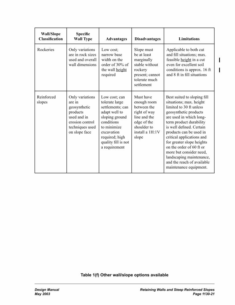
Retaining Walls and Steep Reinforced Slopes Design ManualPage 1130-20 May 2003
Design Manual Retaining Walls and Steep Reinforced SlopesMay 2003 Page 1130-21
Wall/Slope Specific Classification Wall Type Advantages Disadvantages Limitations
Table 1(f) Other wall/slope options available
Rockeries Only variations are in rock sizes used and overall wall dimensions
Low cost; narrow base width on the order of 30% of the wall height required
Slope must be at least marginally stable without rockery present; cannot tolerate much settlement
Reinforced slopes
Only variations are in geosynthetic products used and in erosion control techniques used on slope face
Low cost; can tolerate large settlements; can adapt well to sloping ground conditions to minimize excavation required; high quality fill is not a requirement
Applicable to both cut and fill situations; max. feasible height in a cut even for excellent soil conditions is approx. 16 ft and 8 ft in fill situations
Must have enough room between the right of way line and the edge of the shoulder to install a 1H:1V slope
Best suited to sloping fill situations; max. height limited to 30 ft unless geosynthetic products are used in which long-term product durability is well defined. Certain products can be used in critical applications and for greater slope heights on the order of 60 ft or more but consider need, landscaping maintenance, and the reach of available maintenance equipment.

Retaining Walls and Steep Reinforced Slopes Design ManualPage 1130-22 December 1998
Design Manual Retaining Walls and Steep Reinforced SlopesDecember 1998 Page 1130-23
Typical Mechanically Stabilized Earth Gravity WallsFigure 1130-1a

Retaining Walls and Steep Reinforced Slopes Design ManualPage 1130-22 December 1998
Design Manual Retaining Walls and Steep Reinforced SlopesDecember 1998 Page 1130-23
Typical Prefabricated Modular Gravity WallsFigure 1130-1b

Retaining Walls and Steep Reinforced Slopes Design ManualPage 1130-24 May 2003
Design Manual Retaining Walls and Steep Reinforced SlopesMay 2003 Page 1130-25
Typical Rigid Gravity, Semigravity Cantilever, Nongravity Cantilever, and Anchored Walls
Figure 1130-1c

Retaining Walls and Steep Reinforced Slopes Design ManualPage 1130-24 May 2003
Design Manual Retaining Walls and Steep Reinforced SlopesMay 2003 Page 1130-25
Typical Rockery and Reinforced SlopeFigure 1130-1d

Retaining Walls and Steep Reinforced Slopes Design ManualPage 1130-26 May 2003
Design Manual Retaining Walls and Steep Reinforced SlopesMay 2003 Page 1130-27
MSE Wall Drainage DetailFigure 1130-2

Retaining Walls and Steep Reinforced Slopes Design ManualPage 1130-26 May 2003
Design Manual Retaining Walls and Steep Reinforced SlopesMay 2003 Page 1130-27
Retaining Walls With Traffic BarriersFigure 1130-3

Retaining Walls and Steep Reinforced Slopes Design ManualPage 1130-28 May 2003
Design Manual Retaining Walls and Steep Reinforced SlopesMay 2003 Page 1130-29
Retaining Wall Design ProcessFigure 1130-4a
Design Process - Initiated by region, except by Bridge Office for walls included in bridge preliminary plan.
Coordination with State Bridge and Structures Architect. Bridge Office and Geotech.Branch to identify wall concepts and constraints. (0.5 to 1 month)
Region Develops and submits wall profile, plan, and cross sections(site data) with design request to RME.
See Figure 1130-4b forproprietary
Submit wall site data toBridge Office
Geotech. Branch performsgeotech design andrecommends wall
alternatives as appropriate
(1.5 to 4.5 months)
Bridge Office developswall preliminary plan
(1 to 2 months)
Bridge Officecoordinates with
Geotech. Branch, StateBridge and Structures
Architect, and region forfinal wall selection(0.5 to 1.5 months)
Bridge Officeprepares PS&E(3 to 6 months)
Submit wall site datawith design request to
Geotech Branch
Geotech Branchperforms geotech design
and recommends wallalternatives as appropriate
(1.5 to 4.5 months)
Soil nail nongravitycantilever, anchored, or
other structural walls
Proprietary
Wall Ht
Standard wall (Std. Planwalls, gabions up to 6 ft and
rockeries up to 5 ft)
Wall type:nonstandard,
nonproprietarywalls (1)
Region evaluatespotential alternative wallsystems and coordinateswith the State Bridge andStructures Architect for
final wall selection
Geosynthetic walls andslopes, rockeries
Geotech. Branch and/orBridge Office provides
plan details and specialsand region prepares PS&E
(0.5 to 1 month)
Gabions < 6 ftRockeries < 5ft
Submit wall site datawith design request to
Geotech BranchGeotech by region
Materials Lab(1.5 to 3 months)
Geotech Branch performsgeotech design andrecommends wall
alternatives as appropriate(1.5 to 3 months)
Region evaluatespotential for alternativewall systems to be used
and coordinates withState Bridge and
Structures Architect forfinal wall selection
Standardwall selected
Region prepares wall PS&E(1) Geosynthetic walls, concrete block walls, soil nail
walls, rockeries > 5 ft height, reinforced slopes,and other nonstandard nonpreapproved walls ifthe desired wall type is uncertain.
(2) All other nonstandard, nonproprietary walls(3) See notes and legend on Figure 1130-4b
YesNo
Yes
No
(1)(2)
> 10 ft < 10 ft*
No
Yes
***
***
(3)
(3)

Retaining Walls and Steep Reinforced Slopes Design ManualPage 1130-28 May 2003
Design Manual Retaining Walls and Steep Reinforced SlopesMay 2003 Page 1130-29
Retaining Wall Design Process - ProprietaryFigure 1130-4b
Submit wall site datawith design request to
Bridge Office, with a copyto the Geotech Branch
and the State Bridge and Structures Arcitect
Proprietary
Proprietary
Yes
Geotech Branch performsgeotech. design and
recommends wall alternativesas appropriate
(1.5 to 3 months)
Bridge Office evaluatespotential alternative wallsystems to be used and
coordinates with the StateBridge and Structures
Architect and the region forfinal wall selection(0.8 to 1.5 months)
Bridge Office contactsproprietary wall suppliers toobtain detailed wall design
(2 to 4 months)
Bridge Office prepares PS&E(0.5 to 1 month)
Wall Ht.* *
Submit wall site datawith design request to
Geotech Branch
Geotech Branch performsgeotech. design and
recommends wall alternativesas appropriate (1.5 to 3 moths)
Geotech. by region MaterialsLab(1.5 to 3 months)
Region evaluatespotential alternative
wall systems to be usedand coordinates with the
State Bridge andStructures Architectfor final wall section
Region contacts proprietarywall suppliers to confirm
interest in being included inPS&E
Region prepares wall PS&E(i.e., generalized wall plans,
profiles, and X-sections; othersite specific details; and specificdetails, and Special Provisions)
Bridge Office and GeotechBranch review wall shop plans
on contract (1 month)
Preapprovedwall selected
No
YesNo
> 10 ft < 10 ft*
Notes:The "Bridge Office" refers to the WSDOT Bridge and Structures Office in Headquarters.The "Geotech Branch" refers to the WSDOT Geotechnical Services Branch in Headquarters.The "State Bridge and Structures Architect" refers to the WSDOT Architecture Section of the Bridge and Structures Office in Headquarters.Regarding time estimates:
Assumes no major changes in the wall scope during design.Actual times may vary depending on complexity of project.Contact appropriate design offices for more accurate estimates of time.
Legend:Region provides courtesy coy of region's geotechnical report to Geotechnical Branch
* Assumes soft or unstable soil not present and wall does not support other structures.** The preapproved maximum wall height is generally 33 ft. Some proprietary walls might be less. (Check with the Bridge and Structures Office.)*** If the final wall selected is a different type than assumed, go back through the design process to ensure that all steps have been taken.
Yes
***
***

Retaining Walls and Steep Reinforced Slopes Design ManualPage 1130-30 December 1998
Design Manual Retaining Walls and Steep Reinforced SlopesMay 2003 Page 1130-31
Retaining Wall Bearing PressureFigure 1130-5
Retaining Walls
Design Manual — Working Draft (MBJ) Page 1130-33February 1996
Maximum Soil Pressure (psf) for Reinforced Concrete Retaining Walls
Ht (ft) Type 1 Type 2 Type 3 Type 4 Type 5 Type 6
StaticEarth-quake Static
Earth-quake Static
Earth-quake Static
Earth-quake Static
Earth-quake Static
Earth-quake
5 1611 781 1607 770 630 1033 641 1115 702 971 611 798
6 1838 976 1842 974 705 1254 865 1661 908 1322 746 1141
7 1876 1137 1891 1150 797 1558 882 1904 1179 1782 882 1420
8 2178 1431 2213 1465 995 2047 1025 2323 1510 2419 1246 2091
9 2255 1646 2305 1703 1104 2402 1040 2473 1632 2666 1587 2692
10 2492 2078 2492 2063 1216 2786 1065 2651 1924 3224 1635 2918
11 2693 2474 2713 2482 1197 2787 1174 2907 2046 3475 1795 3233
12 2643 2666 2682 2702 1308 3172 1277 3351 2345 4063 1873 3282
13 2732 2999 2693 2923 1458 3560 1304 3158 2384 4041 1955 3377
14 2972 3508 3065 3624 1539 3790 1444 3643 2683 4611 2269 3941
15 3100 3886 3358 4281 1620 4019 1645 4205 2766 4664 2349 4036
16 3166 4128 3420 4552 1752 4305 1748 4466 2818 4715 2668 4603
17 3247 4372 3472 4795 1833 4534 1849 4723 3149 5293 2846 4927
18 3301 4577 3559 5067 2104 5223 2072 5246 3373 5625 2924 5021
19 3399 4825 3405 4877 2217 5457 2208 5534 3691 6417 3175 5551
20 3570 5205 3724 5585 2461 5983 2312 5822 3685 6422 3405 6103
21 3677 5453 3617 5423 2507 6197 2478 6111 3650 6403 3556 6406
22 3752 5659 3696 5664 2635 6473 2610 6547 3778 6672 3737 6741
23 3866 5910 3810 5939 2715 6693 2650 6729 4110 7280 3889 7046
24 4049 6294 3912 6180 2844 6972 2785 7071 4159 7293 4071 7383
25 4166 6544 4058 6457 2973 7252 2949 7462 4492 7894 4228 7689
26 4250 6752 4172 6698 3103 7532 3047 7711 4664 8241 4410 8031
27 4372 7004 4318 6976 3265 7986 3093 7928 4786 8507 4391 8040
28 4496 7258 4463 7254 3394 8264 3106 8115 4956 8832 4575 8385
29 4621 7512 4609 7533 3524 8544 3241 8402 4920 8819 4724 8693
30 4666 7480 4535 7371 3653 8824 3376 8690 4892 8824 4752 8760
31 4795 7734 4682 7648 3816 9280 3536 9130 5068 9158 4901 9068
32 4924 7988 4828 7926 3707 9422 5194 9433 5088 9415
33 5055 8244 4975 8204 3872 9901 5293 9513 5263 9723
34 5186 8500 5122 8483 5328 9603 5191 9536
35 5318 8757 5269 8763 5456 9877 5378 9880
Notes
2 ft surcharge or traffic barrier with vertical front face.
2 ft surcharge or traffic barrier with sloping front face.
2H:V1 backslope with vertical front face.
2H:1V backslope with sloping front face.

Design Manual Noise BarriersMay 2003 Page 1140-1
Chapter 1140 Noise Barriers
1140.01 General1140.02 References1140.03 Design1140.04 Procedures1140.05 Documentation
1140.01 GeneralThe function of a noise barrier is to reduce traffic noise levels at adjoining areas. The noise abatement decisions are made during the environmental stage of the project development process. This is a highly interactive process. Before a noise barrier is designed, the department must be confident that there is significant need, a cost effective and environmentally acceptable noise barrier, a source of funds, and acceptance by adjacent property owners, local governmental agencies, and the general public.
The designer will find the following preliminary design information in the noise report:
• Sources of noise
• Noise receiver locations
• Predicted level of noise reduction
• Locations of existing and future noise impacts along the project corridor
• Barrier location and height recommendations based on what is feasible and reasonable
Design of a noise barrier project is the result of a team effort coordinated by the project engineer.
This chapter addresses the factors that are considered when designing a noise barrier and the associated procedures and documentation requirements.
1140.02 ReferencesEnvironmental Procedures Manual, M 31-11, WSDOT
Guide Specifications for Structural Design of Sound Barriers, AASHTO
Roadside Manual, M 25-30, WSDOT
Standard Plans for Road, Bridge, and Municipal Construction (Standard Plans), M 21-01, WSDOT
1140.03 DesignThe two basic types of noise barriers are the earth berm and the noise wall. An earth berm can be constructed to the full height required for noise abatement or to partial height in conjunction with a noise wall to reach the required height. A noise wall can be made of concrete, masonry, metal, wood, or other approved innovative products, and can be supported by spread, pile, shaft, or trench footings.
Consideration of the noise report and the visual characteristics of adjacent land forms, vegetation, and structural elements (such as buildings, bridges, and retaining walls) will determine whether a proposed noise barrier might be berm, wall, or both.
An earth berm is the primary alternative if the visual and environmental quality of the corridor will be preserved or enhanced and materials and right of way widths are available. See the Roadside Manual for criteria for determining if a vegetated earth berm is appropriate.
The region uses the noise report and other environmental documents (see the Environmental Procedures Manual) to help determine the location, exposure conditions, length, and heights of the proposed noise barrier.
To design and locate a noise barrier of any kind, consider the following:
• Desired noise abatement
• Future right of way needs
• Cost and constructibility
• Neighborhood character
• Visual character and quality of the corridor
• Future maintenance of the noise barrier and the whole right of way
• Wind

Noise Barriers Design ManualPage 1140-2 May 2003
Design Manual Noise BarriersMay 2003 Page 1140-3
• Supporting soil
• Earthquakes
• Ground water
• Existing drainage systems and water courses
• Exposure to vehicular impacts
• Potential vandalism
• Existing vegetation and roadside restoration required
• Access for maintenance equipment and enforcement, traffic service, and emergency vehicles
• Access to fire hydrants from both sides
• Pedestrian and bicycle access
• Available and attainable width of right of way for berms
• Aesthetic and structural characteristics of available wall designs
• Visual compatibility of each wall design with other transportation structures within the corridor
• Construction limits for footings
• Locations of existing survey monuments
• Access to, and maintenance of, right of way behind a wall, including drainage structures
• Use of right of way and wall by adjacent property owners
• Drainage and highway runoff
• Drainage from adjacent land
• Existing utilities and objects to relocate or remove
• Water and electricity; needs, sources, and access points
A noise barrier must not have anything (such as bridge columns, light fixtures, or sign supports) protruding in such a way as to present a potential for snagging vehicles.
(1) Earth Berm(a) Berm slopes are a function of the material used, the attainable right of way width, and the desired visual quality. Slopes steeper than 2H:1V (3H:1V for mowing) are not recommended. Design the end of the berm with a lead-in slope of 10H:1V and curve it toward the right of way line.
(b) See Chapter 710 and the Standard Plans for guidance on redirectional land forms if the berm is to function as a traffic barrier.
(c) See the Roadside Manual for guidance regarding vegetation on berms and redirectional land forms.
(2) Noise Wall(a) When feasible, to encourage competitive bidding, include several alternate noise wall designs in the contract and permit the contractor to submit alternate designs under the value engineering specification.
(b) There are standard noise wall designs in the Standard Plans manual. Additional designs are in various stages of development to become standard plans. The draft-standard design sheets and other preapproved plans are available from the Bridge and Structures Office. The Bridge and Structures Office also works with the regions to facilitate the use of other designs as bidding options.
(c) When a noise wall has ground elevations that are independent of the roadway elevations, a survey of ground breaks (or cross sections at 25-ft intervals) along the entire length of the wall is needed for evaluation of constructibility and to assure accurate determination of panel heights.
(d) Size of openings (whether lapped, door, or gated) depends on the intended users. Agencies such as the local fire department can provide the necessary requirements. Unless an appropriate standard plan is available, such openings must be designed and detailed for the project.
(e) When a noise wall is inside the Design Clear Zone, design its horizontal and vertical (ground elevation) alignment as if it were a rigid concrete traffic barrier. See Chapter 710 for maximum flare rates.
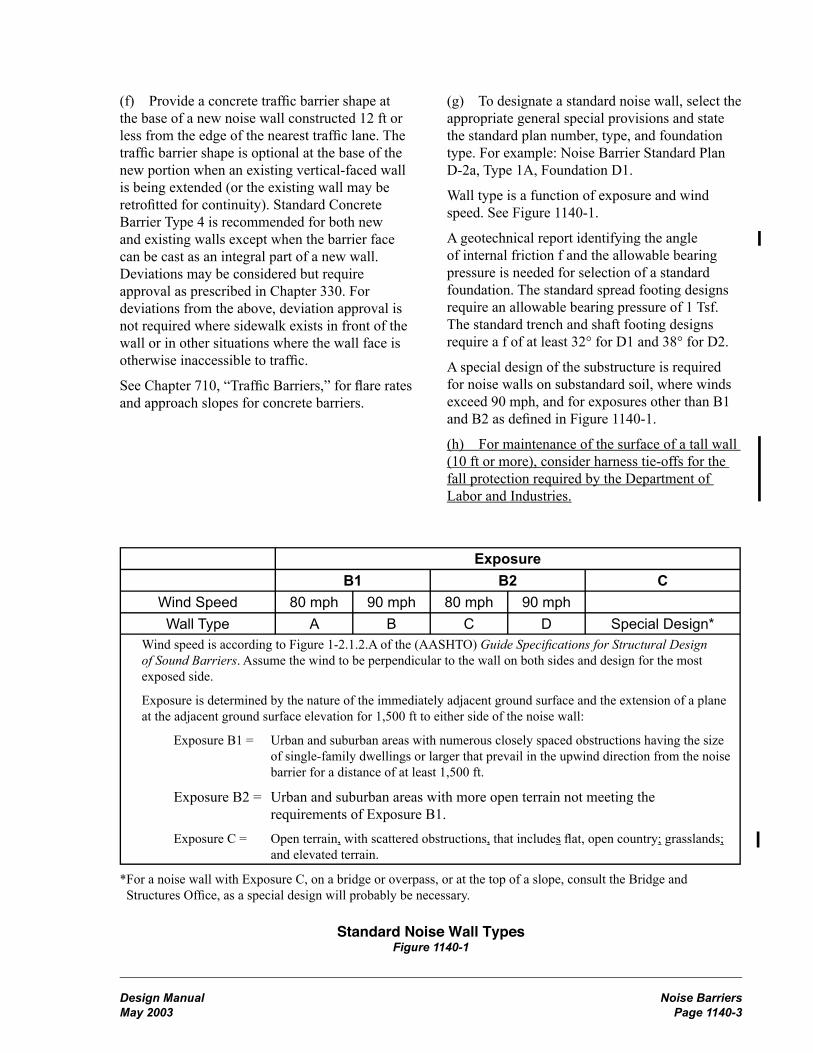
Noise Barriers Design ManualPage 1140-2 May 2003
Design Manual Noise BarriersMay 2003 Page 1140-3
ExposureB1 B2 C
Wind Speed 80 mph 90 mph 80 mph 90 mphWall Type A B C D Special Design*
Wind speed is according to Figure 1-2.1.2.A of the (AASHTO) Guide Specifications for Structural Design of Sound Barriers. Assume the wind to be perpendicular to the wall on both sides and design for the most exposed side.
Exposure is determined by the nature of the immediately adjacent ground surface and the extension of a plane at the adjacent ground surface elevation for 1,500 ft to either side of the noise wall:
Exposure B1 = Urban and suburban areas with numerous closely spaced obstructions having the size of single-family dwellings or larger that prevail in the upwind direction from the noise barrier for a distance of at least 1,500 ft.
Exposure B2 = Urban and suburban areas with more open terrain not meeting the requirements of Exposure B1.
Exposure C = Open terrain, with scattered obstructions, that includes flat, open country; grasslands; and elevated terrain.
*For a noise wall with Exposure C, on a bridge or overpass, or at the top of a slope, consult the Bridge and Structures Office, as a special design will probably be necessary.
(f) Provide a concrete traffic barrier shape at the base of a new noise wall constructed 12 ft or less from the edge of the nearest traffic lane. The traffic barrier shape is optional at the base of the new portion when an existing vertical-faced wall is being extended (or the existing wall may be retrofitted for continuity). Standard Concrete Barrier Type 4 is recommended for both new and existing walls except when the barrier face can be cast as an integral part of a new wall. Deviations may be considered but require approval as prescribed in Chapter 330. For deviations from the above, deviation approval is not required where sidewalk exists in front of the wall or in other situations where the wall face is otherwise inaccessible to traffic.
See Chapter 710, “Traffic Barriers,” for flare rates and approach slopes for concrete barriers.
(g) To designate a standard noise wall, select the appropriate general special provisions and state the standard plan number, type, and foundation type. For example: Noise Barrier Standard Plan D-2a, Type 1A, Foundation D1.
Wall type is a function of exposure and wind speed. See Figure 1140-1.
A geotechnical report identifying the angle of internal friction f and the allowable bearing pressure is needed for selection of a standard foundation. The standard spread footing designs require an allowable bearing pressure of 1 Tsf. The standard trench and shaft footing designs require a f of at least 32° for D1 and 38° for D2.
A special design of the substructure is required for noise walls on substandard soil, where winds exceed 90 mph, and for exposures other than B1 and B2 as defined in Figure 1140-1.
(h) For maintenance of the surface of a tall wall (10 ft or more), consider harness tie-offs for the fall protection required by the Department of Labor and Industries.
Standard Noise Wall TypesFigure 1140-1
Noise Barriers Design ManualPage 1140-4 May 2003
Design Manual Noise BarriersMay 2003 Page 1140-5
1140.04 ProceduresThe noise unit notifies the Project Engineer’s Office when a noise barrier is recommended in the noise report.
The Project Engineer’s Office is responsible for interdisciplinary teams, consultation, and coordination with the public, noise specialists, maintenance, construction, region’s Landscape Architecture Office (or the Roadside and Site Development Services Unit), right of way personnel, Materials Laboratory, State Bridge and Structures Architect (in the Bridge and Structures Office), Bridge and Structures Office, CAE Support Team, Access and Hearings Engineer, consultants, and many others.
The region evaluates the soils (see Chapters 510 and 1110) and, if a noise wall is contemplated, obtains a list of acceptable wall design options by sending information pertaining to soils and drainage conditions, the alignment, and heights of the proposed wall to the State Bridge and Structures Architect.
If a vegetated earth berm is considered, see the Roadside Manual for procedures.
The State Bridge and Structures Architect coordinates with the Bridge and Structures Office, Hydraulics Design Branch, Geotechnical Branch, and the region to provide a list of acceptable standard, draft-standard, and preapproved-proprietary noise wall designs, materials, and finishes that are compatible with existing visual elements of the corridor. Only wall designs from this list may be considered as alternatives. Design visualizations of the highway side of proposed walls (available from the CAE Support Team in Olympia) must be limited to options from this list. The visual elements of the private-property side of a wall are the responsibility of the region unless addressed in the environmental documents.
After the noise report, any changes to the dimensions or location of a noise barrier must be reviewed by the appropriate noise unit to determine the impacts of the changes on noise abatement.
On limited access highways, any opening in a wall or fence (for pedestrians or vehicles) must be coordinated with the Access and Hearings Engineer and approved by the State Design Engineer.
On nonlimited access highways, an access connection permit is required for any opening (approach) in a wall or fence.
The Bridge and Structures Office provides special substructure designs to the regions upon request; reviews contract design data related to standard, draft-standard, and preapproved designs; and reviews plans and calculations that have been prepared by others. (See Chapter 1110.)
Approval of the Bridge and Structures Office and the Architecture Office is required for any attachment or modification to a noise wall and for the design, appearance, and finish of door and gate type openings.
Approval of the State Bridge and Structures Architect is required for the final selection of noise wall appearance, finish, materials, and configuration.
1140.05 DocumentationA list of the documents that are required to be preserved in the Design Documentation Package (DDP) or the Project File (PF) is on the following web site:
http://www.wsdot.wa.gov/eesc/design/projectdev/

Design Manual IndexMay 2003 Page 1
Index
AABSORB 350, 720-3ABSORB 350 impact attenuator, 720-12Acceleration lane, 910-8, 940-7Access, 1420-1
approach criteria, 1420-3, 1420-5approach types, 1420-6bicycle facilities, 1420-2, 1420-4, 1420-6bus stops, 1420-2, 1420-4, 1420-5control design policy, 1420-1control development, 1430-1crossroads at interchange ramps, 1420-1frontage roads, 1420-7full control, 1420-1hearing, 210-12, 1430-2hearing plan, 1430-2interchanges and intersections, 1420-3,
1420-5mailboxes, 1420-2, 1420-4, 1420-5modifications to limited access plans,
1420-8modified control, 1420-4multiple use of right of way, 1420-7partial control, 1420-2pedestrian facilities, 1420-2, 1420-4,
1420-5, 1420-6railroad approaches, 1420-6report, 1430-1report plan, 1430-1road approaches, 1420-1roundabouts, 915-13utilities, 1420-2, 1420-4, 1420-5
Access control, 120-7full, 1420-1modified, 1420-4partial, 1420-2
Access Point Decision Report (APD Report),1425-1
definitions, 1425-2documentation, 1425-10eight policy topics, 1425-3finding of engineering & operational
acceptability, 1425-4flow chart, 1425-14, 1425-15procedures, 1425-2references, 1425-1
report and supporting analysis, 1425-4review levels, 1425-11, 1425-12
Accessible route, pedestrian, 1025-1ADA, definition, 1025-1ADIEM 350 impact attenuator, 720-4, 720-12Administrative appeal hearing, 210-15ADT (average daily traffic), 700-1Agency Request Budget (ARB), 120-15Agreements, 240-10
airspace, highway, utility, 1420-7Air quality, 240-6Airport System Plan, 120-13Airport-highway clearance, 240-4, 240-13, 630-3Airspace agreement, 1420-7Alignment
horizontal, 620-1monuments, 1450-2vertical, 630-1
Americans with Disabilities Act (ADA), 1025-1Approaches
full access control, 1420-1modified access control, 1420-4partial access control, 1420-2railroad, 1420-6road, 920-1, 1420-1
Approvalaccess hearing plan, 1430-2access report, 1430-1corridor, FHWA, 220-9DEIS, 220-6design, level of, 330-7design reviews and, 330-9, 330-10Environmental Classification Summary,
220-2FEIS, 220-8findings and order, 210-14governmental agencies, 240-1materials source, 510-2PS&E process, 330-11, 330-12Study Plan and a Public Involvement Plan
(EIS), 220-3Work Order Authorization, CE, 220-9Work Order Authorization, EA, 220-10Work Order Authorization, EIS, 220-3
Archaeological sites, 220-5, 220-10, 220-11Army Corps of Engineers, 240-1

Index Design ManualPage 2 May 2003
Arterial HOV, 1050-5, 1050-9Asphalt pavement
estimating, 520-3Audible warning signals, 1025-3Authorized road approach, 920-1Auxiliary lanes, 620-4, 1010-1
chain-up area, 1010-5climbing lanes, 1010-2emergency escape ramps, 1010-4left-turn, 910-6one-way left-turn, 910-6passing lanes, 1010-2railroad grade crossings, 930-2right-turn, 910-8shoulder driving for slow vehicles, 1010-3slow moving vehicle turnouts, 1010-3speed change, 910-8two-way left-turn, 910-7
Average weekday vehicle trip ends (AWDVTE),920-1
BBarricades, 810-11Barrier curbs, 440-6Barrier delineation, 830-5Barrier terminal
buried terminals, 710-6definition, 710-1flared terminal, 710-7, 710-23nonflared terminal, 710-7, 710-23other anchor, 710-8project requirements, 710-2
Barrier transitionbeam guardrail transitions, 710-10connections, 710-9definition, 710-1project requirements, 710-2transitions and connections, 710-10
Barriers, traffic, 710-1barrier deflections, 710-4barrier design, 710-3beam guardrail, 710-5bridge rails, 710-15cable barrier, 710-11concrete barrier, 710-12definition, 710-1delineation, 830-5documentation, 710-17dragnet, 710-16flare rate, 710-4
length of need, 710-5, 710-19moveable, 810-10project requirements, 710-1redirectional land forms, 710-15shared use path (bicycle), 1020-13shy distance, 710-4steel backed timber guardrail, 710-14stone guardwalls, 710-15water filled barriers, 710-16, 810-9
Basic design level, 410-1minor safety and minor preservation work,
410-1required safety items of work, 410-1
Basic safety, 410-1Beam guardrail. See GuardrailBerms, earth
noise wall, 1140-2traffic barrier, 710-15
Bicycle Advisory Committee, 1020-4Bicycle coordinator, 1020-1, 1020-3, 1020-7,
1020-17Bicycle facilities, 1020-1, 1020-7
access, 1020-6alignment, horizontal, 1020-13barriers, traffic, 1020-13bicycle parking, 1020-7bicycle route, 1020-1bike lane, 1020-1, 1020-4, 1020-16bike lanes cross freeway off and on-ramps,
1020-16bike route, 1020-17bikeway, 1020-1bollards, 1020-15bridges, 1120-4clearance, 1020-8, 1020-14, 1020-15crossings, 1020-9design clear zone, 1020-13design speed, 1020-13drainage, 1020-15drainage grates, 1020-17intersections, 1020-8lighting, 1020-7, 1020-15maintenance, 1020-6parking, 1020-16pavement markings, 1020-15 through 17planning, 1020-2railroad crossing, 1020-12roundabouts, 915-12Rules of the Road (RCW 46.61), 1020-3,
1020-16

Design Manual IndexMay 2003 Page 3
rural bicycle touring routes, 1020-2shared roadway, 1020-2, 1020-4, 1020-17shared use path, 1020-2, 1020-3,
1020-7 through 12sidewalks, 1020-4sight distance, 1020-14signed shared roadway, 1020-2signing, 1020-15State Highway System Plan, 1020-2storage facilities, 1020-7structures, 1020-7, 1020-14superelevation, 1020-13traffic signals, 1020-11, 1020-17tunnels, 1020-15undercrossings, 1020-15widths, 1020-8, 1020-15
Bicycle Policy Plan, 120-10Bituminous surface treatment, 520-5
estimating, 520-5Bollards, 1020-15Borrow site. See Sundry sitesBoundaries, international, 1410-2Brakemaster impact attenuator, 720-1, 720-8Bridge rails, 710-15
concrete safety shape, 710-15pedestrian, 1025-8project requirements, 710-2thrie beam bridge rail retrofit criteria,
710-24thrie beam retrofit, 710-16
Bridge site data, 1110-1check list, 1110-5stream crossings, 1110-2
Bridges, 1120-1approach slab, 1120-4design, 1120-1end slopes, 640-9existing structures, 1120-1geotechnical investigation, 510-11horizontal clearance, 1120-2location, 1120-1medians, 1120-2new structures, 1120-1pedestrian and bicycle facilities, 1120-4protective screening for highway structures,
1120-5rail end treatment, 1120-4railroad, 1120-2rails, 710-15site design elements, 1120-1
slope protection, 1120-4slope protection at watercrossings, 1120-5structural capacity, 1120-1vertical clearance, 1120-2widths for structures, 1120-2
Bridle trail, 1020-1Budgets, 120-15Buffer strip, pedestrian, 1025-5Buffer-separated HOV lanes, 1050-1, 1050-3
1050-9, 1050-11Bulb out, 1025-1Bus facilities, 1060-1
berths, 1060-7disabled accessibility, 1060-12grades, 1060-11intersection, 1060-11lane widths, 1060-11passenger amenities, 1060-10paving sections, 1060-10transfer/transit centers, 1060-6turning path template, 1060-23, 1060-24,
1060-35, 1060-36vehicle characteristics, 1060-11
Bus stops and pullouts, 1060-7designation and location, 1060-7far-side, 1060-8mid-block, 1060-9near-side, 1060-8placement, 1060-8pullouts, 1060-9
CCable barrier, 710-11
locations on slopes, 710-23Caissons, 1130-2Cantilever sign supports, 820-3Capacity
highway, 610-1roundabouts, 915-7
Capacity analysis, 915-7CAT impact attenuator, 720-1, 720-8Categories, 915-1Cattle passes, R/W, 1410-2CE, definition, 220-1Center line rumble strips, 700-8Central Island, 915-11Certification of documents, 330-4Chain link
fencing, 1460-2gates, 1460-3

Index Design ManualPage 4 May 2003
Chain-off areas, 1010-5Chain-up areas, 1010-5Channelization, 910-6
curbing, 910-9devices, 810-11islands, 910-9left-turn lanes, 910-6right-turn lanes, 910-8speed change lanes, 910-8
Checklist, environmentalClass II and III, 220-3, 220-10definition, 220-1
Circulating roadway, 915-9City streets, 440-3Classification
functional, 440-2terrain, 440-3
Clear run-out area, 700-1Clear zone, 700-2
definitions, 700-1Design Clear Zone, 700-2,
DM Supplement 11/1/2002distance table, 700-10ditch section, 700-3ditch section examples, 700-14inventory form, 700-11, 700-12recovery area, 700-2recovery area example, 700-13roundabouts, 915-12
Clearance. See also Vertical clearance andHorizontal clearance
airport-highway, 240-4, 630-3bikeway, 1020-8
Climbing lanes, 1010-2Closed circuit television cameras (CCTV), 860-1Cloverleaf, 940-3Coast Guard, U.S. (USCG), 240-3, 1110-3
permit, 1110-3Collector, 440-1, 440-14Collector distributor roads, 940-9Combined hearings, 210-15Commercial approaches, 920-3Communication towers
geotechnical investigation, 510-7Comprehensive plans, 120-4, 120-5Concrete barrier, 710-12
concrete barrier terminals, 710-14shapes, 710-12
Concurrent flow HOV lanes. See Nonseparated
HOV lanesCondemnations, 1410-5Cones, 810-11Conflict, 910-1Conforming road approach, 920-1Connections, 940-6 through 9Construction permits, 1410-3Contour grading, 1310-1Control monuments, 1450-2Controllers, signal, 850-8Corner clearance, 920-1, 920-3Corridor hearing, 210-11Corridor Management Plan (CMP), 120-11Corridor or project analysis, 325-1, 330-3
sample, 330-12, 330-15County roads, 440-3Crash cushion. See Impact attenuatorCritical fill slope, 700-1Cross sections
encroachment (RR), 930-3interchange ramp, 940-5roadways, 640-2rock cuts, 640-7side slopes, 640-7stepped slopes, 640-8
Cross slope, 430-2, 640-4roadways, 640-2shoulders, 640-4traveled way, 640-2
Crossingrailroad grade, 930-1
Crossovers, median, 960-1Crossroads, 910-1, 910-3
ramp terminal intersections, 940-9Crosswalks, 850-8, 1025-1
marked, 1025-6unmarked, 1025-6
Crown slope for divided roadways, 640-10Cul-de-sacs, 1420-7Culvert ends, 700-5Curb cuts, 1020-12
shared use path, 1020-12Curbs, 440-6, 910-9Current Law Budget (CLB), 120-15Curves
horizontal, 620-2superelevation, 640-4vertical, 630-2
Cut slopes, 640-10, 640-11, 640-12, 640-14,700-4
Design Manual IndexMay 2003 Page 5
DDatums, surveying, 1440-2DDS. See Design Decision SummaryDE. See Design ExceptionDeceleration lane, 910-8, 940-8Decision sight distance, 650-4DEIS, definition, 220-2Delineation, 830-1
guide posts, 830-4pavement markings, 830-1traffic barriers, 830-5wildlife warning reflectors, 830-5
Department of Defense (DOD), 1120-3Design
approval level, 330-7hearing, 210-12level, 325-4speed, 430-1, 440-1, 440-3, 940-4variance, 325-4variance inventory, 330-3vehicle, 430-3, 910-4
Design Clear Zone, 700-2 through 700-6definition, 700-1distance table, 700-10ditch sections, 700-3ditch section examples, 700-14roundabouts, 915-12
Design considerations for intersections at grade,910-3
configurations, 910-3crossroads, 910-3spacing, 910-4traffic analysis, 910-3
Design Decisions Summary (DDS), 330-2Design documentation, approval, and process
review, 330-1design approval, 330-5design documentation, 330-3process review, 330-5project definition phase, 330-2project development, 330-2purpose, 330-1
Design Exception (DE), 325-4Design matrix procedures, 325-1
procedures, 325-3project type, 325-4selecting a design matrix, 325-3terminology, 325-1using a design matrix, 325-4
Designated state highways map, 120-11Developer initiated intersections, 910-13Deviation, 325-5, 330-4, 340-6
documentation, 330-4documentation content list, 330-15
Diamond interchange, 940-3Direct access ramp, HOV, 1050-2, 1050-3,
1050-5, 1050-9. HOV Direct AccessDesign Guide, Draft, M 22-98
Directional interchange, 940-3Disabled access, transit, 1060-12Discipline Report, 220-1Distribution facilities, 620-2Ditch inslopes, 430-3DMS, definition, 860-4DNS, definition, 220-1Documentation
design, 330-1environmental, 220-1
Drainage, 940-4, 1210-1Drainage ditches in embankment areas, 640-9Drilled shafts, 1130-2Drop lanes, 910-8Drums, 810-11Dynamic message signs (DMS), 860-4
EEA, definition, 220-1Easements, 1420-7
perpetual, 1410-3right of way, 1410-2temporary, 1410-3
Ecology, Department of, 240-6ECS, definition, 220-1EIS, definition, 220-2Elevators, 1025-9Emergency escape ramps, 1010-4Emergency vehicle preemption, 850-11Encroachment, railroad, 930-3Endangered species, 210-7, 220-7, 220-8,
220-10, 240-2, 240-11Enhanced enforcement, 810-8Environmental documents
APD report, 1425-9geotechnical report, 510-5project, 220-1
Environmental hearing, 210-11Environmental Protection Agency, 240-5

Index Design ManualPage 6 May 2003
Environmental Review Summary (ERS), 330-2Erosion prevention, 1350-2ERS. See Environmental Review SummaryEscape ramps, 1010-4Evaluate Upgrade (EU), 325-5, 330-4
documentation, 330-4documentation content list, 330-15
Exit patternuniformity, 940-4
FFarmlands, 210-7, 220-5, 220-10, 220-11,
240-11Federal agencies, 240-1Federal aid
environmental categories, 220-2landscape projects, 1320-4R/W documents, 1410-6
Federal Aviation Administration (FAA), 240-4Federal Energy Regulatory Commission (FERC),
240-5Federal lands
R/W transactions, 1410-4FEIS, definition, 220-2Fencing, 1460-1
chain link, 1460-2design criteria, 1460-1documentation, 1460-4fencing types, 1460-2gates, 1460-3limited access highways, 1460-1managed access highways, 1460-2procedure, 1460-3special sites, 1460-2wire fencing, 1460-3
Ferry System Plan, 120-13FHWA - WFLHD, 240-4Filing requirements, monuments, 1450-3Fill slopes, 430-3, 640-10, 640-11, 640-12,
640-14, 700-4Findings
engineering and operational acceptability,1425-4
Findings and order, 210-14plan, 220-13, 1430-2
Fire hydrants, 700-6Fish and Wildlife, Department of, 240-6Fixed objects, 700-4Flood plains, 210-7, 220-5, 220-7, 220-8,
220-10, 220-11, 1210-1
Flyer stop, 1050-2, 1050-3, 1050-5.HOV Direct Access Design Guide,Draft, M 22-98
FONSI, definition, 220-2Forest Service, U.S. (USFS), 240-3Freeway lighting applications, 840-11Freight and Goods Transportation System
(FGTS), 120-7Freight Rail Plan, 120-9Frontage roads, 620-3, 1420-7Full design level, 440-1
city streets and county roads, 440-3curbs, 440-6design speed, 440-3functional classification, 440-2geometric design data, 440-3grades, 440-7medians, 440-5parking, 440-6pavement type, 440-7shoulders, 440-4state highway system, 440-3state highways as city streets, 440-3structure width, 440-7terrain classification, 440-3traffic lanes, 440-4
Functional classification, 120-6, 440-1, 440-2Funding. See Programming
GG-R-E-A-T impact attenuator, 720-5, 720-13Gabion walls, 1130-10Gates, 1460-3Geographic Information System (GIS), 1440-3Geometric
design data, 440-3Geometric cross section, 640-1
medians, 640-6minimum radius for normal crown section,
640-5outer separations, 640-6roadsides, 640-7roadways, 640-2shoulders, 640-4superelevation, 640-4traveled way cross slope, 640-2turning roadway widths, 640-2
Geometric plan elements, 620-1arrangement of lanes, 620-3distribution facilities, 620-2

Design Manual IndexMay 2003 Page 7
frontage roads, 620-3horizontal alignment, 620-1horizontal curve radii, 620-2lane transitions, 620-4median width transitions, 620-4number of lanes and arrangement, 620-3pavement transitions, 620-4
Geometric profile elements, 630-1airport clearance, 630-3alignment on structures, 630-2coordination of vertical and horizontal
alignments, 630-2design controls, 630-1grade length, 630-2length of grade, 630-2maximum grades, 630-2minimum grades, 630-2minimum length of vertical curves, 630-2railroad crossings, 630-3vertical alignment, 630-1
Geometricshorizontal alignment, 620-1vertical alignment, 630-1
Geosynthetic soil reinforcement, 1130-9Geosynthetics, 530-1
applications, 530-2, 530-16definition, 530-2design approach, 530-3design process, 530-12design responsibility, 530-11ditch lining, 530-6documentation, 530-11erosion control, 530-5function, 530-2separation, 530-4site-specific designs, 530-10soil stabilization, 530-5standard specification, 530-9temporary silt, 530-20temporary silt fence, 530-6types, 530-14types and characteristics, 530-1underground drainage, 530-3
Geotechnical investigation, design, and reporting,510-2
bridge foundations, 510-11buildings, 510-7cantilever signs, 510-7communication towers, 510-7consultants, 510-14
documentation, 510-14earthwork, 510-4ferries projects, 510-13hydraulic structures, 510-5key contacts, 510-2luminaire, 510-7noise walls, 510-8park and ride lots, 510-7permits, 510-3reinforced slopes, 510-8rest areas, 510-7retaining walls, 510-8rockslope, 510-10sign bridges, 510-7signals, 510-7site data, 510-3surfacing report, 510-14unstable slopes, 510-9
Geotextilesdescriptions, 530-1standard specification, 530-9types, 530-15
Glare screens, 700-8, 700-9, 700-17Global Positioning System (GPS), 1440-2Gore, 940-1, 940-8Governmental agencies, 240-1Grade crossing, railroad, 930-1Grade intersections, 910-1Grades, 430-2, 440-7, 915-11
bikeway, 1020-6change/city and town/adoption, 240-9maximum, 440-9, 440-10, 440-12, 440-14,
630-2minimum, 630-2ramp, 940-5roundabouts, 915-11shared use path, 1020-14vertical alignment, 630-2
Grading, contour, 1310-1Gravity walls, 1130-1Guardrail
beam guardrail, 710-5locations on slopes, 710-6placement cases, 710-9post installation, 710-20steel backed timber guardrail, 710-14terminals and anchors, 710-6thrie beam, 710-5, 710-24W-beam, 710-5
Index Design ManualPage 8 May 2003
Guide posts, 830-4placement, 830-7
Guide sign plan, 820-4Guidelines for wall/slope selection, 1130-5
cost considerations, 1130-8cut and fill considerations, 1130-5facing options, 1130-7feasible wall and slope heights and
applications, 1130-7settlement and deep foundation support
considerations, 1130-6summary, 1130-8supporting structures or utilities, 1130-7
HHAR, definition, 860-4Hazard, 700-4
definition, 700-1fixed objects, 700-4median considerations, 700-6side slopes, 700-4water, 700-6
Headlight glare, 700-8Hearings, 210-6
access, 210-12, 1430-2administrative appeal, 210-15advertising, 210-7combined, 210-15corridor, 210-11design, 210-12environmental, 210-11, 220-7, 220-12examiner, 210-13findings and order, 210-14formal, 210-4informal, 210-4notice, 210-7open format, 210-4preparation, 210-8requirements, 210-6sequence, 210-16study plan, 210-3, 210-11
Heritage tour routebarrier, 710-4designations, 120-11
Hex-Foam Sandwich impact attenuator, 720-5,720-14
High accident corridor (HAC), 1025-2High accident locations (HAL), 1025-2
High occupancy vehicle (HOV) facilities, 915-1, 1050-1, DM Supplements5/3/2000 & 9/28/1999
arterial street, 1050-5, 1050-9buffer-separated, 1050-3, 1050-9design criteria, 1050-7direct access ramp, 1050-2, 1050-3, 1050-5,
1050-9, HOV Direct Access DesignGuide, Draft, M 22-98
enforcement, 1050-7enforcement areas, 1050-9, 1050-10,
1050-13 through 1050-15facility type, 1050-3flyer stop. 1050-2, 1050-3, 1050-5,
HOV Direct Access Design Guide,Draft, M 22-98
freeway, 1050-3ITS, 1050-7lane termination, 1050-9nonseparated, 1050-3, 1050-9preliminary design and planning, 1050-2ramp meter bypass design criteria, 1050-9,
1050-13, 1050-14separated roadway, 1050-3, 1050-8,
1050-11signs and pavement markings, 1050-10vehicle occupancy designation, 1050-6
Highwayairport clearance, 240-4as city streets, 440-3
Highway Access Management ClassificationReports, 120-7
Highway advisory radio (HAR), 860-4Highway-highway separation, 1110-3Highway-railroad separation, 1110-3Highways and Local Programs Service Center,
120-10Horizontal alignment, 620-1Horizontal clearance, bridge, 1120-2Horizontal curve radii, 620-2HOV facilities. See High occupancy vehicle
facilitiesHydraulic considerations, 1210-1
channel changes, 1210-2flood plain, 1210-1roadway drainage, 1210-2runoff, 1210-3stream crossings, 1210-2subsurface discharge, 1210-3subsurface drainage, 1210-3

Design Manual IndexMay 2003 Page 9
Hydraulic design, 1210-1design responsibility, 1210-3geotechnical investigation, 510-5hydraulic considerations, 1210-1safety considerations, 1210-3
IIDT, 220-3Illumination, 840-1, 915-13
additional illumination, 840-3bridges, 840-5construction zones and detours, 840-4design criteria, 840-5illumination calculation example, 840-21required illumination, 840-2roundabouts, 915-13
Impact attenuator systems, 720-1design criteria, 720-5object markers, 830-5older systems, 720-5permanent installations, 720-1selection, 720-6work zone installation, 720-3
Inertial barrier, 720-3, 720-5, 720-12Inscribed diameter, 915-9Intelligent transportation systems (ITS), 860-1
closed circuit television cameras, 860-1dynamic message signs, 860-4highway advisory radio, 860-4HOV bypass, 860-4HOV facilities, 1050-7motorist information, 860-4National ITS Architecture, 860-1public information components, 860-4surveillance, control, and driver information,
860-1traffic data collection, 860-2traffic flow control, 860-3traffic operations center (TOC), 860-2Traffic Systems Management Center
(TSMC), 860-2Venture Washington, 860-1
Interchanges. See Traffic interchangesInternational boundaries, R/W, 1410-2Intersections at grade, 430-3, 910-1, 910-2
angle, 430-3channelization, 910-6configurations, 910-3design considerations, 910-3
design vehicle, 430-3documentation, 910-13four leg intersection, 910-2interchange ramp terminals, 910-12island, 910-2, 910-9leg, 910-2median crossover, 910-2plans, 910-13right-turn corners, 910-5roundabouts, 910-2, 910-10, 915-1sight distance, 910-11spacing, 910-4tee (T) intersection, 910-2traffic control, 910-12transit, 1060-11U-turns, 910-10wye (Y) intersection, 910-2
Interstate, 440-2, 440-9Irrigation, 1330-1Islands, 910-2, 910-9
compound right-turn lane, 910-9location, 910-9roundabouts, 915-11size and shape, 910-9
ITS, definition, 860-1
JJoint use approach, 920-2Jurisdiction Over State Highways, DM
Supplement 1/22/2003
LLabor and Industries, Department of (L&I),
240-9Land corner record (form), 1450-7Landscaping, 1300-2, 1320-1, 1330-1, 1350-1Lane, 940-6
balance, 940-6bike, 1020-1, 1020-4drop, 910-8number and arrangement, 620-3reduction, 940-6transitions, 620-4width, 430-1, 440-4
Lane lines. See Pavement markingsLeft-turn lanes, 910-6
one-way, 910-6storage, 910-6two-way, 910-7

Index Design ManualPage 10 May 2003
Length of need, traffic barrier, 710-5calculation, 710-19definition, 710-1on curves, 710-20
Level of Development Plan, 330-2Licensed professionals, certification by, 330-4,
1450-2, 1450-3Light standards, 700-6, 840-7
geotechnical investigation, 510-7LMA impact attenuator, 720-5, 720-14Load rating, bridges, 1120-1Local agency
bridge design, 1120-2initiated intersections, 910-13
Longitudinal barrier. See Traffic barrierLongitudinal easements, railroad, 930-3Loop ramp connections, 940-9Low clearance warning signs, 1120-3Luminaire. See Light standards
MMailbox location and turnout design, 700-16Mailboxes, 700-5Maintenance site. See Sundry sitesManual on Uniform Traffic Control Devices
(MUTCD), 820-1, 830-1, 850-1, 860-2,1025-1, 1120-3
Maps. See also Plansmonumentation, 1450-3
Marked crosswalks, 1025-6Masonry concrete blocks, 1130-7Mast arm signal standards, 850-14Master Plan for Limited Access Highways,
120-7, 330-2Materials sources, 510-1, 510-16Matrix. See Design matrix proceduresMechanically Stabilized Earth (MSE), 1130-1,
1130-22Median, 440-5, 640-6
design, 640-6safety considerations, 700-6transitions, 620-4width, 440-5
Median barrier, 700-6supplement August 1, 2001
Median crossovers, 960-1analysis, 960-1approval, 960-2design, 960-1supplement August 1, 2001
Memorandum of AgreementAdvisory Council, SHPO, and FHWA,
220-7Historic Preservation, 220-9
Memorandum of UnderstandingConservation Commission, 220-6Fish and Wildlife, 240-6Highways Over National Forest Lands,
240-3USCG and FHWA, 240-3WSP, 1040-2
Metal bin walls, 1130-11Metropolitan Planning Organizations (MPO),
120-3Metropolitan Transportation Improvement
Program (MTIP), 120-4, 120-14Midblock pedestrian crossing, 1025-1Mileposts
markers, 820-4sign, 820-4
Military Traffic Management CommandTransportation Engineering Agency
(MTMCTEA), 1120-3Minor arterial, 440-2, 440-12Minor operational enhancement projects, 340-1
matrix procedures, 340-3project approval, 340-5project types, 340-2selecting a matrix, 340-4using a matrix, 340-4
Minor safety and minor preservation work, 410-1Modified design level, 430-1
bridges, 430-3cross slope, 430-2design speed, 430-1fill slopes and ditch inslopes, 430-3intersections, 430-3profile grades, 430-2ramp lane widths, 430-1roadway widths, 430-1stopping sight distance, 430-2
Monotube cantilever sign supports, 820-3Monotube sign bridges, 820-3Monument Database, WSDOT, 1440-2Monumentation, 1450-1
alignment monuments, 1450-2control monuments, 1450-2DNR permit, 1450-3filing requirements, 1450-3land corner record, 1450-3

Design Manual IndexMay 2003 Page 11
monumentation map, 1450-3other monuments, 1450-3property corners, 1450-3
Mopeds, 1020-1Motorist information, 860-4
additional public information components,860-4
dynamic message signs, 860-4highway advisory radio, 860-4
Mountable curbs, 440-6Moveable barriers, 810-10MTMCTEA, 1120-3MUTCD, 820-1, 830-1, 850-1, 860-2, 1025-1
NN-E-A-T impact attenuator, 720-4, 720-12National Highway System (NHS), 325-6, 325-7,
330-4, 330-5, 440-2National ITS Architecture, 860-1Natural Resources, Department of, 240-8Navigable waters, 240-3NEPA, definition, 220-1New Jersey shape barrier, 710-13Noise barriers, 1140-1
design, 1140-1documentation, 1140-4earth berm, 1140-2geotechnical investigation, 510-8noise wall, 1140-2procedures, 1140-4wall types, 1140-3
Noncommercial approaches, 920-3Nonconforming road approach, 920-2Nonrecoverable slope, 700-2Nonseparated HOV lanes, 1050-2, 1050-3,
1050-5, 1050-7, 1050-9, 1050-11Notional live load, 1120-1
OObject markers, 830-5Off connections, 940-8Office of Urban Mobility, 120-12On connections, 940-7One-way left-turn geometrics, 910-7Open house meetings, 210-4Outer separations, 640-2, 640-6Overhead sign installations, 820-3
PPAL, 1025-2Park and ride lots, 1060-1
access, 1060-3bicycle facilities, 1060-5design, 1060-2drainage, 1060-5fencing, 1060-6geotechnical investigation, 510-7illumination, 1060-5internal circulation, 1060-3landscape, 1060-6maintenance, 1060-6motorcycle facilities, 1060-5pavement design, 1060-5pedestrian movement, 1060-4shelters, 1060-5site selection, 1060-2stall size, 1060-4traffic control, 1060-5
Parking, 440-6roundabouts, 915-13
Partial cloverleaf, 940-3Passing lanes, 1010-2Passing sight distance, 650-1
horizontal curves, 650-2no passing zone markings, 650-2vertical curves, 650-2
Path, bicycle. See Shared use pathPavement
transitions, 620-4widening, 620-4
Pavement markingslongitudinal, 830-1materials, 830-6roundabouts, 915-12transverse, 830-2
Pavement structure, 520-1asphalt concrete pavement, 520-3base and surfacing quantities, 520-7bituminous surface treatment, 520-5estimating tables, 520-1typical section, 520-6
PCMS, 810-10PD. See Project definitionPedestrian accident locations (PAL), 1025-2Pedestrian bridge, 1120-2Pedestrian connectivity, 1025-3Pedestrian crossings at-grade, 1025-6

Index Design ManualPage 12 May 2003
Pedestrian design considerations, 1025-1activity generators, 1025-4bridges, 1120-4bulb out, 1025-1cross slope, 1025-6crosswalk, 1025-1diagonal ramps, 1025-7facilities, 1025-1, 1025-4funding programs, 1025-2grade, 1025-6grade separations, 1025-8human factors, 1025-3illumination and signing, 1025-9landing, 1025-1midblock pedestrian crossing, 1025-1policy, 1025-2raised median, 1025-2refuge island, 1025-2roundabouts, 915-12shared use paths, 1025-5shoulders, 1025-5sidewalk ramps, 1025-7sidewalks, 1025-5transit stops, 1025-9walking and hiking trails, 1025-5walking rates, 1025-3
Pedestrian Policy Plan, 120-10Pedestrian risk projects, 1025-2Pedestrian-friendly, 1025-1Permits
construction, 1410-3geotechnical permits, 510-3governmental agencies, 240-1remove/destroy monument, 1450-5right of way, 1410-2traffic signal, 850-2
Photogrammetry, 1440-3Physical barriers, 810-9Pit sites, R/W, 1410-2Planning, 120-1
definitions, 120-2legislation and policy development, 120-2linking transportation plans, 120-13planning and programming, 120-16planning at WSDOT, 120-7planning to programming, 120-15references, 120-1
Plansaccess hearing, 210-13, 1410-6, 1430-2access report, 1430-1environmental study, 210-3, 220-2, 220-3,
220-4findings and order, 220-13, 1430-2guide sign, 820-4interchange, 940-10intersection, 910-13limited access, 1410-2limited access, modifications to, 1420-8PS&E, R/W, 1410-4public involvement, 210-3, 220-2right of way, 1410-1, 1410-3, 1410-4Water Pollution Control (WPCP), 240-7
Pollution control, 240-6Portable changeable message signs, 810-10Portable traffic signals, 810-12Preliminary signal plan, 850-14Principal arterial, 440-2, 440-10Private land
R/W transactions, 1410-4Profile grades, 440-7Program Management Office, 120-15Programming
R/W appraisal and acquisition, 1410-6R/W funding, 1410-4
Project analysis, 325-1, 330-3sample, 330-12, 330-15
Project definition phase, 330-2Design Decisions Summary (DDS), 330-2Environmental Review Summary (ERS),
330-2Project Definition (PD), 330-3project summary, 330-2
Property corners, 1450-3Proprietary items, 720-7
impact attenuator, 720-7irrigation, 1330-1noise walls, 1140-4PS&E process approval, 330-11retaining wall design process, 1130-28,
1130-29retaining walls, design, 1130-9retaining walls options, 1130-18roadside devices, 1300-3traffic barrier terminals, 710-7traffic barriers, special, 710-14
Protective screening for highway structures, 1025-8, 1120-5

Design Manual IndexMay 2003 Page 13
Public information, 810-1Public Involvement Plan, 220-2Public Transportation and Intercity Rail
Passenger Plan for Washington State, 120-8Public Transportation and Rail Division, 120-8
QQ Program, 340-1QuadGuard cz impact attenuator, 720-4QuadGuard Elite impact attenuator, 720-2QuadGuard impact attenuator, 720-2, 720-9QuadTrend-350 impact attenuator, 720-1, 720-8Quarry site. See Sundry sites
RRailroad
approaches, access control, 1420-6crossings, 630-3, 930-1easements, 930-3encroachments, 930-3grade crossing orders, 930-3grade crossings, 930-1longitudinal easements, 930-3preemption, 850-11R/W transactions, 1410-4stopping lanes, 930-2traffic control systems, 930-1
Ramp, 940-4cross section, 940-5design speed, 940-4grade, 940-5HOV direct access. HOV Direct Access
Design Guide, Draft, M 22-98HOV ramp meter by pass, 1050-9, 1050-13,
1050-14lane increases, 940-5lane widths, 430-1, 940-5meters, 940-6sight distance, 940-5terminal intersections at crossroads, 940-9terminals, 910-12
REACT 350 impact attenuator, 720-3, 720-4,720-11
Recoverable slope, 700-2,Recovery area, 700-2, 700-13Redirectional land forms, 710-15Regional Transportation Improvement Program
(RTIP), 120-14
Regional Transportation Planning Organizations(RTPO), 120-4, 120-6
Regulatory traffic control strategies, 810-8Reinforced slopes, 1130-1
geotechnical investigation, 510-8Reports
access, 1430-1discipline, 220-5
Required safety items of work, 410-1Rest areas, 1030-1
geotechnical investigation, 510-7Retaining walls, 1130-1
aesthetics, 1130-4anchored walls, 1130-2, 1130-24classifications, 1130-1constructibility, 1130-4coordination with other design elements,
1130-4cut and fill considerations, 1130-5data submission for design, 1130-13design principles, 1130-2design requirements, 1130-2drainage design, 1130-3gabion walls, 1130-10, 1130-23geotechnical investigation, 510-8geotechnical and structural design, 1130-3investigation of soils, 1130-3metal bin walls, 1130-11, 1130-23MSE gravity walls, 1130-2, 1130-22nongravity cantilevered walls, 1130-2,
1130-24nonpreapproved proprietary walls, 1130-12nonstandard nonproprietary walls, 1130-12nonstandard walls, 1130-9, 1130-13preapproved proprietary walls, 1130-11prefabricated modular gravity walls, 1130-2,
1130-23proprietary wall systems, 1130-9rigid gravity walls, 1130-1, 1130-24rockeries, 1130-2, 1130-25semigravity walls, 1130-2, 1130-24settlement and deep foundation support
considerations, 1130-6standard walls, 1130-9, 1130-10traffic barrier shape, 1130-3wall and slope heights, 1130-7
Revegetation, 1300-2, 1320-1Reviews and approvals
design, 330-9, 330-10PS&E process, 330-11, 330-12
Index Design ManualPage 14 May 2003
Right of way, 1410-1appraisal and acquisition, 1410-4easements and permits, 1410-2multiple use, 1420-7plans, 1410-1programming for funds, 1410-4special features, 1410-2transactions, 1410-4
Right-turn at intersections, 910-5corners, 910-5lanes, 910-8pocket and taper, 910-8
Road approaches, 920-1, 1420-1commercial, 920-3connection category, 920-2corner clearance, 920-3design considerations, 920-2design template, 920-2drainage requirements, 920-4noncommercial, 920-3right of way, 1410-2sight distance, 920-3spacing, 920-3type, 920-3
Road closures, 810-5Roadside Classification Plan, 1300-2Roadside development, 1300-1
documentation, 1300-2recommendations, 1300-3requirements, 1300-2Roadside Classification Plan, 1300-2Roadside Manual, 1300-2
Roadside safety, 700-1clear zone, 700-2definitions, 700-1Documentation, 700-9fixed objects, 700-4guidelines for embankment barrier, 700-15hazards, 700-4headlight glare, 700-8median considerations, 700-6rumble strips, 700-7side slopes, 700-4water, 700-6
Roadsides, 640-7bridge end slopes, 640-9drainage ditches in embankment areas,
640-9
roadway sections in rock cuts, 640-7side slopes, 640-7stepped slopes, 640-8
Roadway lighting applications, 840-13Roadway rumble strips, 700-7Roadways, 640-2
shoulders, 640-4traveled way cross slope, 640-2turning roadway widths, 640-2widths, HOV facilities, 1050-8, 1050-11,
1050-12Rock anchors, 1130-2Rock cuts, 640-7
geotechnical investigation, 510-10Rock, investigation, 510-1Rock walls, 1130-2ROD, definition, 220-2Roundabouts, 910-2, 910-10, 915-1
access, 915-13bicycles, 915-12capacity analysis, 915-7categories, 915-5circulating roadway, 915-9deflection, 915-8design clear zone, 915-12design speed, 915-8elements, 915-3entry, 915-9exit, 915-10geometric design, 915-7grades, 915-11illumination, 915-13inscribed diameter, 915-9islands, 915-11locations not normally recommended, 915-1locations not recommended, 915-2parking, 915-13pavement marking, 915-12pedestrians, 915-12recommended locations, 915-1sight distance, 915-10signing, 915-12superelevation, 915-11transit facilities, 915-13
Route, bicycle, 1020-1, 1020-17Route continuity, 940-4Route Development Plans, 120-11, 330-2Rumble strips, 700-7Runoff, 1210-3

Design Manual IndexMay 2003 Page 15
SSafety, basic, 410-1Safety rest areas, 1030-1Safety, roadside. See Roadside safetySC&DI, 860-1Scale sites, 1040-1Scenic byway, 120-11
barrier, 710-4School walk route, 1025-7Scoping, 220-3Screening, 810-12Section 4(f), 220-6, 220-9, 220-10, 220-11
definition, 220-2lands, 210-7, 220-7, 220-8, 240-4
Semidirectional interchange, 940-3Sentre impact attenuator, 720-5, 720-13SEPA, definition, 220-1Shared roadway, 1020-4, 1020-17Shared use paths, 1020-2, 1025-5Sheet piles, 1130-2Shoreline Development Permit, 240-9Shotcrete facing, 1130-7Shoulders
cross slope, 640-4driving for slow vehicles, 1010-3functions, 440-4islands, 910-9rumble strips, 700-7slope, 640-4turnouts, 1010-3width, 430-1, 440-4width for curb, 440-6
Shy distance, 710-4definition, 710-1structure, 440-7
Side slopes, 700-4Sidewalk ramps, 1025-7Sidewalks, 1020-4, 1025-5Sight distance, 650-1, 940-5, 940-7
bicycle, 1020-14decision, 650-4intersections, 910-11passing, 650-1road approaches, 920-3roundabouts, 915-10stopping, 650-2, DM Supplement 10/9/2002
Sight triangle, 910-11Sign posts, 700-5
Signalgeotechnical investigation, 510-7intersection warning sign, 850-13phasing, 850-4supports, 700-6, 850-13warrants, 850-4
Signed shared roadway. See Bicycle facilitiesSigning, 820-1
bikeways, 1020-15, 1020-17bridges, 820-3, 1120-3cantilever sign structures, 820-3design components, 820-2foundations, 820-3geotechnical investigation, 510-7ground mounted signs, 820-3guide sign plan, 820-4heights, 820-2horizontal placement, 820-4illumination, 820-3lateral clearance, 820-2lighting fixtures, 820-3location, 820-2longitudinal placement, 820-2mileposts, 820-4overhead installation, 820-3posts, 700-5, 820-3roundabouts, 915-12service walkways, 820-4structure mounted sign mountings, 820-3vertical clearance, 820-4
Silt fence, 530-6Single point (urban) interchange, 940-3Single slope barrier, 710-13Site data for structures, 1110-1
additional data for grade separations, 1110-3
additional data for waterway crossings,1110-2
additional data for widenings, 1110-4CAD files and supplemental drawings,
1110-1highway-highway separation, 1110-3highway-railroad separation, 1110-3required data for all structures, 1110-1
Slopebridge end, 640-9geotechnical investigation, 510-8protection, 1120-4protection at watercrossings, 1120-5roadways, 640-2

Index Design ManualPage 16 May 2003
rock cuts, 640-7shoulders, 640-4side slopes, 640-7stabilization, 1350-2stepped, 640-8traveled way, 640-2
Slow moving vehicleturnouts, 1010-3
Soil bioengineering, 1350-1design responsibilities and considerations,
1350-3streambank stabilization, 1350-2upland slope stabilization, 1350-2
Soil nail walls, 1130-8Soils, 510-1
investigation, 510-1soldier piles, 1130-2Spacing
interchanges, 940-4intersections, 910-4road approaches, 920-3
Span wire, 850-14Special permits and approvals, 240-1Speed change lanes, 910-8, 940-7, 940-8Speed, design, 440-3, 940-4Splitter island, 915-11Stairways, 1025-9State Commute Trip Reduction Program, 120-8State Highway System Plan, 120-5, 120-10,
120-11, 330-2rural bicycle touring routes, 1020-2urban bicycle projects, 1020-2
State highways as city streets, 440-3Statewide Transportation Improvement Program
(STIP), 120-5, 120-14Steel backed timber guardrail, 710-14Stepped slopes, 640-8Stockpiles, R/W, 1410-2Stone guardwalls, 710-15Stopping sight distance, 430-2, 650-2
crest vertical curves, 650-3effects of grade, 650-3existing, 650-3horizontal curves, 430-2, 650-4sag vertical curves, 650-4vertical curves, 430-2
Storage length, left-turn lane, 910-6Strain poles
steel, 850-14timber, 850-14
Streambank stabilization, 1350-2Striping. See Pavement markingsStructural capacity, 1120-1Structure width, 440-7Structures. See BridgesStudy plan
environmental, 220-2, 220-3, 220-4value engineering, 315-2
Sundry sitespublic lands, 240-8right of way, 1410-2source of materials, 510-1
Superelevation, 640-4existing curves, 640-5intersections, 640-5, 640-27rates, 640-4, 640-24, 640-25, 640-26roundabouts, 915-11runoff for highway curves, 640-5runoff for ramp curves, 640-6shared use path, 1020-13
Surface Transportation Program, 120-7Surfacing materials, 510-1
base and surfacing quantities, 520-7investigation, 510-1pavement structure, 520-1surfacing report, 510-14
Surveying and mapping, 1440-1after construction is completed, 1440-2datums, 1440-2during design and development of the
PS&E, 1440-1during the project definition phase, 1440-1geographic information system (GIS),
1440-3global positioning system (GPS), 1440-2photogrammetric surveys, 1440-3procedures, 1440-1WSDOT monument database, 1440-2
TTaper, 910-8. See also Lane transitionsTAU-II impact attenuator, 720-2, 720-10TDM Strategic Plan, 120-9Temporary concrete barriers, 810-10Temporary pavement markings, 810-12Temporary road approach, 920-2Terrain classification, 440-3Textured crosswalks, 1025-6Thrie beam. See GuardrailTMA, 810-10

Design Manual IndexMay 2003 Page 17
TRACC impact attenuator, 720-4, 720-12Traffic
data collection, 860-2islands, 910-9lanes, 440-4operations center (TOC), 860-2signal design, 850-4signal permit, 850-2
Traffic analysisintersections, 910-3
Traffic barrier. See Barriers, traffic, 700-2Traffic control, 810-1
channelization, 910-6intersections, 910-12
Traffic control plans, 810-9Traffic control signals, 850-1
control equipment, 850-8crosswalks and pedestrians, 850-8detection systems, 850-10electrical design, 850-15foundation design, 850-14funding, construction, maintenance, &
operation, 850-3intersection design considerations, 850-7preemption systems, 850-11preliminary signal plan, 850-14signal displays, 850-12signal phasing, 850-4signal supports, 850-13signal warrants, 850-4strain poles, 850-14third party agreement signals, 850-3
Traffic flow control, 860-3HOV bypass, 860-4ramp meters, 860-3
Traffic interchanges, 940-1collector distributor roads, 940-9connections, 940-6 through 940-9design, 940-2lane balance, 940-6on two-lane highways, 940-10patterns, 940-3plans, 940-10ramp design speed, 940-4ramp grade, 940-5ramp terminal intersections, 940-9ramp terminals, 910-12ramp widths, 940-5ramps, 940-4sight distance, 940-1 through 5
spacing, 940-4weaving sections, 940-9
Traffic signal standards, 700-6Traffic Systems Management Center (TSMC),
860-2Transit benefit facilities, 1060-1
bus stops and pullouts, 1060-7disabled accessibility, 1060-12flyer stops, 1050-5grades, 1060-11intersection, 1060-11lane widths, 1060-11park and ride lots, 1060-1passenger amenities, 1060-10paving sections, 1060-10priority preemption, 850-11roundabouts, 915-13transfer/transit centers, 1060-6vehicle characteristics, 1060-11
Transitions and connections, traffic barrier, 710-8Transitions, pavement, 620-4Transportation Demand Management Office,
120-9Transportation Facilities and Services of
Statewide Significance, 120-6Travel Demand Management Program (TDM),
120-12Traveled way, 440-2, 640-2, 700-2Traveled way cross slope, 640-2Traveler services, 1030-1Trees, 700-5TREND impact attenuator, 720-5, 720-13Truck
climbing lanes, 1010-2escape ramps, 1010-4weigh sites, 1040-1
Truck mounted attenuator, 720-5, 810-10Tubular markers, 810-11Turnbacks, 1420-7Turning path template, 910-14, 910-15, 910-16,
1060-23, 1060-24, 1060-35, 1060-36Turning roadway widths, 640-2
HOV facilities, 1050-8, 1050-12Turnouts, 1010-3Two-way left-turn lanes, 910-7
UU-turns, 910-10U.S. Coast Guard, 240-3, 1110-3

Index Design ManualPage 18 May 2003
Uniformity of exit pattern, 940-4Unmarked crosswalk, 1025-6Utilities
agreements, 240-10R/W transactions, 1410-4
Utility poles, 700-6
VValue Engineering (VE), 315-1
implementation phase, 315-3job plan, 315-5procedure, 315-1selection phase, 315-1team tools, 315-7
Vegetation, 1320-1Vehicle turning path template, 910-14, 910-15,
910-16, 1060-23, 1060-24, 1060-35, 1060-36Venture Washington, 860-1Vertical alignment, 630-1
design controls, 630-1length of grade, 630-2maximum grades, 630-2minimum grades, 630-2minimum length of vertical curves, 630-2structures, 630-2
Vertical clearancenew bridge, railroad, 1120-2new bridge, roadway, 1120-2pedestrian bridge, 1120-2signing, bridge, 1120-3structures, 1120-2
WW-beam guardrail. See GuardrailWalking and hiking trails, 1025-5Walls, 1130-1
geotechnical investigation, 510-8noise, 1140-2retaining, 1130-1
Warrants, 850-4, 1010-2Washington State Patrol
median crossovers, 960-2weigh sites, 1040-1
Washington’s Transportation Plan (WTP), 120-4,120-8
Waste Sites, R/W, 1410-2Watchable Wildlife Program, 120-12Water, hazard, 700-6Water quality, 240-6Water-filled barriers, 810-9
Weaving sections, 940-9Weigh sites, 1040-1
federal participation, 1040-4permanent facilities, 1040-2planning, development, and responsibilities,
1040-1portable facilities, 1040-3shoulder sites, 1040-4
Wetlands, 210-7, 220-5, 220-7, 220-8, 220-10,220-11, 240-1, 1210-2
Wheelchair, 1025-4Wide QuadGuard impact attenuator, 720-9Wide REACT 350 impact attenuator, 720-11Widening
pavement, 620-4Width
bridge, 440-7HOV facilities, 1050-8, 1050-11, 1050-12lane, 430-1, 440-4shoulder, 430-1, 440-4
Wildlife, Department of, 240-6Wildlife warning reflectors, 830-5Wire fencing, 1460-3Work zone classification, 810-2
intermediate-term stationary work zones,810-2
long-term stationary work zones, 810-2mobile work zones, 810-2short-duration work zones, 810-2short-term stationary work zones, 810-2
Work zone safety, 810-6flaggers, 810-7road users, 810-7workers, 810-6
Work zone traffic control, 810-1documentation, 330-4
Work zone types, 810-3crossover, 810-3detour, 810-3intermittent closure, 810-3lane closure, 810-3lane constriction, 810-3median use, 810-3multiple lane separation, 810-3shared right of way, 810-3shoulder use, 810-3temporary bypass, 810-3
ZZones, transition
shared use path, 1020-12