design, construction, and initial experiments with high
TRANSCRIPT
Scholars' Mine Scholars' Mine
Masters Theses Student Theses and Dissertations
1969
Design, construction, and initial experiments with high hydrostatic Design, construction, and initial experiments with high hydrostatic
pressure extrusion device pressure extrusion device
Edward Moniz Jorge
Follow this and additional works at: https://scholarsmine.mst.edu/masters_theses
Part of the Chemical Engineering Commons
Department: Department:
Recommended Citation Recommended Citation Jorge, Edward Moniz, "Design, construction, and initial experiments with high hydrostatic pressure extrusion device" (1969). Masters Theses. 7059. https://scholarsmine.mst.edu/masters_theses/7059
This thesis is brought to you by Scholars' Mine, a service of the Missouri S&T Library and Learning Resources. This work is protected by U. S. Copyright Law. Unauthorized use including reproduction for redistribution requires the permission of the copyright holder. For more information, please contact [email protected].

DESIGN, CONSTRUCTION, AND I NITIAL EXPERIMENTS WITH
HIGH HYDROSTATIC PRESSURE EXTRUSION DEVICE
BY
EDWARD MONIZ JORGE, 1944-
A
THESIS
submitted to the faculty of
UNIVERSITY OF MISSOURI - ROLLA
in partial fulfillment of the requirements for the
Degree of
MASTER OF SC I ENCE IN CHEMICAL ENGINEERING
Rolla, Missouri
1969
Approved by
~J.Jl..~~~~(advisor) Ba&n.£J: I( ..6 '??L. "
T2326 c. I 43 pages
183318
ABSTRACT
The purpose of this study was to des1~n and operate
equipment with which the study of polymer extrusion would
be possible at hydrostatic pressures up to 50,000 psi.
11
By hydrostatic pressure is meant the pressure of the region
of the extrudate. A study of the ef~ects of back pressure
on the extrusion of silicone gum was attempted.

iii
ACKNOWLEDGMENTS
The 8uthor w~shes to extend his deepest appreciation
to Dr. Gary K. Patterson for his assistance, inspiration
and encouragement throughout this investigation.
He also wishes to thank Dr. Robert L. Davis as
well as the Mechanics Department for their assistance
and use of their laboratory facilities.
He is grateful to Phillips Petroleum Company and
Diamond Shamrock Corp. for their financial support.
Finally he is indebted to his narents for their
constant encouragement.

iv
TABLE OF CONTENTS
ABSTRACT ••....•• . . . . . . . . . . . . . . . . . . . . . . . . . . . . . . . . . . . . . . Page • •• 11
ACKNOWLEDGMENTS. . . . . . . . . . . . . . . . . . . . . . . . . . . . . . . . . . . . . . . . .111
LIST OF ILLUSTRATIONS. . . . . . . . . . . . . . . . . . . . . . . . . . . . . . . . . . . •. v
LIST OF TABLES ..••• . . . . . . . . . . . . . . . . . . . . . . . . . . . . . . . . . . . . . .vi
I. INTRODUCTION. . . . . . . . . . . . . . . . . . . . . . . . . . . . . . . . . . . . . . . • 1
II. REVIE1-f OF LITERATURE. • • • • • • • • • • • • • • • • • • • # • • • • • • • • • • .2
III. EXPERIMENTAL • •••••••••••••••••.•.••••••••••.•••••••. 9
A. EQUIPMENT. . . . . . . . . . . . . . . . . . . . . . . . . . . . . . . . ·9
1 • RHEOMETER. . . . . . . . . . . . . . . . . . . . . . . . . . . . . . . . ·9
2. DIFFERENTIAL PRESSURE CELL. . . . . . . . . . . . . . . 12
B. EXPERIMENTAL PROCEDURE .•••••••.• . ............ . 15
1 • DIFFERENTIAL PRESSURE CELL. . . . . . . . . . . . . . . 15
2. RHEOMETER. . . . . . . . . . . . . . . . . . . . . . . . . . . . . . . • 17
IV. DISCUSSION ••••••••••••••••. . ..................... . • 19
A. EQUIPMENT DEVELOPMENT. . . . . . . . . . . . . . . . . . . . . . . . • 1 9
B. EXPERIMENTAL RESULTS •••.••••••••••.••••••••••• 25
v. CONCLUSION ••.•.••• .•.•• • • · · • • • • · • · · • • • • • • • · • · · · • · • • 34
VI. BIBLIOGRAPHY. • •••.• •. • · · • • · • • • • • · • · · · · • • · • · • • · • 35
VII. VITA ....•....•••.•. •.•········ • • · · · · · · • · · · · · · • · • · · .37
v
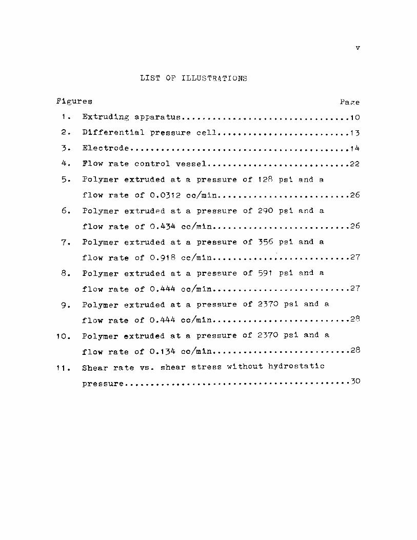
LIST OF ILLUSTRATIONS
Figures Page
1. Extruding apparatus ••••••••..•.••..•.•••.•.•...••••• 10
2. Differential pressure cell ••••••••••••••••••••••...• 1 3
3. Electrode ..............•............................ 14
4. Flow rate control vessel .••••••••••••••••••••••••••• 22
5. Polymer extruded at a pressure of 128 psi and a
flow rate of 0.0312 cc/min •••••••.••.••••••••..•.••• 26
6. Polymer extrudPd at a pressure of 290 psi and a
.flow rate of 0.434 cc/min ••....•.••.•.•..•••••.•.••• 26
7. Polymer extruded at a pressure of 356 psi and a
flow rate of 0.918 cc/min •.•••••••••• ~ •.....•.•••••• 27
8. Polymer extruded at a pressure of 591 psi and a
.flow rate o.f 0.444 cc/min ••••••.•..•...........•.•.. 27
9. Polymer extruded at a pressure of 2370 psi and a
flow rate o.f 0.444 cc/min ••••••••••••••.••.••....••• 28
10. Polymer extruded at a pressure of 2370 psi and a
.flow rate of 0.134 cc/min ••••••••••••••.•••••.••.••• 28
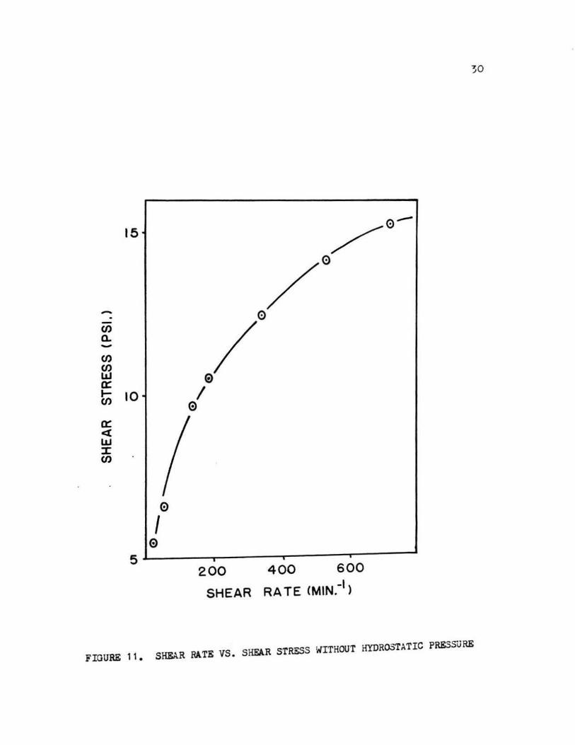
11. Shear rate vs. shear stress without hydrostatic
pressure ................. ....... · .. · · · · · · • · · · · · · · · · · 30

vi
LIST OF TABLES
Page Table I. Results of the extrusion of SE-30 without
hydrostatic pressure •.•••••••••••••••••.•••.•• 32
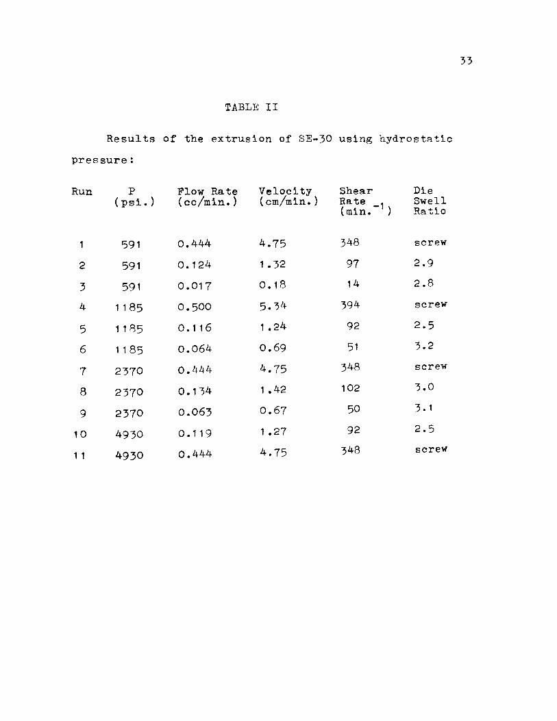
Table II. Results of the extrusion of SE-30 using
hydrostatic pressure •.••••••••••.••..•.•.•...• 33
1
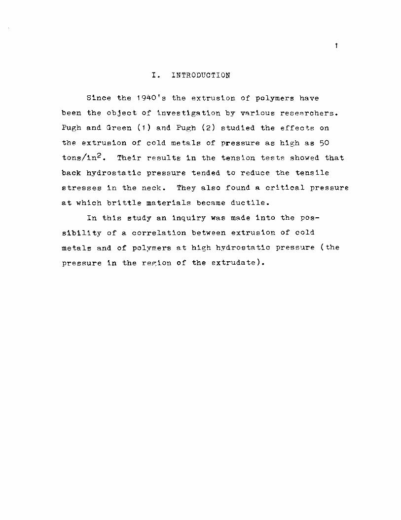
I. INTRODUCTION
Since the 1940's the extrusion of polymers have
been the object of investigation by various rese~rchers.
Pugh and Green (1) and Pugh (2) studied the effects on
the extrusion of cold metals of pressure as high as 50
tons/in2. Their results in the tension tests showed that
back hydrostatic pressure tended to reduce the tensile
stresses in the neck. They also found a critical pressure
at which brittle materials became ductile.
In this study an inquiry was made into the pos
sibility of a correlation between extrusion of cold
metals and of polymers at high hydrostatic pressure (the
pressure in the region of the extrudate).

II. REVIEW OF LITF~ATURE
When a material is subjected to a force it will
respond to that force by undergoing a deformation or
strain. Rheology is, by definition, the science of
deformation and flow of matter. Different types of
stress, such as, tensile, compressive and shearing are
a result of the manner in which the stress is applied.
The response to these different types of stress depends
to some extent on different molecular mechanisms (3).
Materials whose response is completely recoverable
(return to original shape after stress is·removed} are
called elastic. Materials whose resnonse is completely
irrecoverable are called viscous. Materials which show
both viscous and elastic response are CRlled visco
elastic.
2
The rate of change of veloctiy transverse to the
flow direction of a liquid is called the shear rate of
the liquid. The shear force per unit area of the liquid
(in a plane normal to the transverse direction taken
above) is called the shear stress. These are the
independent and dependent variables describing the
steady-state rheology of the liquid; i.e. the shear
stress acting on the liquid causes it to res~ond with
a certain shear rate characteristic of the properties
of that particular liquid.
For laminar flow of Newtonian liquids in capillarie~
under isothermal conditions, the flow may be described
by the Hagen-Poiseuille equation. The ratio of the shear
stress to shear rate, both evaluated at the wall, is
called the viscosity of the fluid. The relationships of
the variables may be written as:
{ w (D~P)/4L
'tf w = 32Q/(1rD3) = 8U/D
~ = {wf"O'w
where:
( 1 )
(2)
( 3)
~w =shear stress at the capillary wall, lbf/in2.
D = diameter of capillary, in.
&P = pressure drop for flow through capillary, psi.
L = length of capillary, in.
tw = shear rAte at the capillary wall, sec.-1
Q volumetric rate of flow, in.3/sec.
U = average velocity in capillary, in./sec.
~ = viscosity, lbsf sec./in. 2
Since Equations (1) and (2) were developed for
laminar flow of Newtonian fluids they have to be mod-
ified to describe tht capillary flow of non-Newtonian
fluids. For Equation 1, a small end correction is
considered effective to describe shear stress of non
Newtonian fluids. According to Dundevain and Klein (4)
following Rabinowitsch (5) the true shear rate at the
wall is obtained from:
3
f.'th' = 1(3 + 1/(d(lnl~)/d(ln0w))'4'w
where J" w is calculAtr:d by Equ:OJ.tion 2.
Many different tynes of extrusion rheometers (6-10)
have been used to study canillary flow of ~olten ooly-
mers and flow instabilities. In the 1940's Spencer and
Dillion (11) and Nason (12) showed that there exists a
critical shear rqte at and above which the extrudate be-
4
comes deformed. Subsequently, the same e~fects were observed
by Tordella (1~) in the extrusion of polyethylene and
other polymers.
Tordella found the oriv,in of polymer deform8tion to
be in the vicinity of the apnroach to the capillary. He
found these distortions to be caused by a macrosl~p or
tesring within the polymer as a result of slow relax2tion
times relative to the deformation ratPs - the stress
imposed on the polymer exceeds its strength and fracture
is the end result. The critical shear rate or that shear
rate at which fracture occurs was found by Tordella (14)
to be dependent on the polymer, its molecul8r WPi~ht, the
extrusion temperature and the shape of the inlet to the
capillary. He did not indicate how these variables
affected the critical she~r rate.
Bagley and Schreiber (15) usin~ nolvethylene with a
carbon tracer found defor~ation of the extrudate to be
caused by a break of the polymer just above the die inlet.
With the oriented polymer at the center of the reservoir
breaking, it forced the surrounding polymer to be ex
truded;since the polymer surrounding the filament w~s
not aligned, distortions resulted in the extrusion. By
using a die with a large L/D ratio, Bagley and Schreiber
found distortions of the extrudate minimal due to the
fact that flow times in the capillary were much greater
and the polymer had time to relax.
5
Tordella (14), Clegg (16), Bagley, Birks and Schrieber
(15, 17), Bialas and White (18), Ballenger and White (19)
made visual studies of the flow patterns of low density
polyethylene using different types of dies. In the c~se
of a flat entrance die, all of the above authors observed
large dead spaces in the corners of the reservoir just
above the capillary and that at the approach to the
capillary the polymer moved through a funnel shaped
region with the dead spaces defining its sides. It was
also observed that the dead space to the right of the
observer cycles in a counter-clockwise motion and that
the left dead space cycles in a clockwise motion.
Ballen~er and White (19) in studying the flow patterns
in polymer melts above the capillary entrance found the
dead regions to vary in size for different polymers. The
amount of eddying occurring in the region above the
capillary entrance, or the secondary circulating flows,
were found to depend on the deviation of the melt from
Newtonian fluid behavior. The rP.lationship between
secondary flow patterns and rheological properties is
being further investigated by them.
Cle~g (16) in studying the extrusion of polymPrs
postulated the theory that the shape of the extrudate not
only depended on the shear stress but also on the rate
of chan~e of the shear stress at the capillary's en
trance. Bagley and Schreiber (15), usin~ high speed
photography and bl8ck cqrbon as a tracer in polyethylene,
studied the effects of die entry geometry on polymer
melt fracture. Using dies with different conical angles,
they concluded that melt fracture occurs at the same
shear stress in both tapered and flat entry dies. Ex
trudate distortion was found by Bagley and Schreiber to
be less severe in the case of a tapered die for two
reasons. First in the cBse of a tapered die the dead
region is either eliminated or reduced, thus diminishing
the region of unoriented material. Second, the melt
fracture lifetime was reduced. As mentioned previously,
with the breaking and retracting of the highly oriented
polymer, unoriented material surroundin~ it surges into
the capillary entrRnce to take its place. This continues
until the unoriented polymer suddenly breaks and retracts
causing the highly oriented material to flow. The time
it takes for the original material to reestablish it-
6
self is called the melt fracture lifetime and it de
creases as the die entry angle decreases. As a consequence
7
of these two phenomena extrudate distrotion is reduced.
Visual studies of various polymers made by Bialas and
White (20) showed two distict tynes of extrudate distortion.
One type was characterized by screw thread appearance
typical of high density polyethylene. The other tyne was
characterized by an uneven swell of varying period
appearance typical of low density polyethylene.
Matsuoka and Mazwell (21) in their study of the
effects of extreme pressure on polymers found the struct-
ural cha~gPs, i.e. recrystallization and second-order
transition of state, induced by addition of a high
hydrostatic pressure (up to 70,000 atm) on linear high
polymers to be time dependent. It was observed by them
that the faster the material is compressed, the less
pressure and deformation is required for the structural
changes.
Bradbury a.nd Leininger (22) studied the effect of
pressures as high as 100,000 atms on various polvmers.
They found the density chan~e of nolyethylene to vary
from -0.0001 g/cc at a pressure of 90 x 103 atms and a
holding time of 2 min. to +0.0020 g/cc at a pressure of
98 x 10; atms and a holding time of 60 min. At least in
the case of polyethylene they found the density chan~e
to be dependent on the holding ti~e. It was observed
by them that tne changes in density did not reflect the
the changes in molecular composition. The physical changes
in polymers observed by Bradbury and Leininger at extreme
pres~ures and elevated temper~tures were small and no
general compression effects were noticed.
Westover (23) and Maxwell and Jung (24) extruded
polyethylene and other polymers under hydrost8tic pres
sures and elevated temperatures were small and no ~eneral
comnression effects were noticed.
Westover (23) and Maxwell and Jung (24) extruded
polyethylene and other polymers under hydrost8.tic pres
sures un to 25,000 psi. It W8S their observation that
viscosity increased exponentially with pressure for
most polymers used.

III. EXPERIM}.~NT.AL
In choosing a polymer for this study certa tn re
quirements ha d to be met . The p olyme r ha d to ha ve a
molecula r we i ght high enou~h to be able to su s t~ in its
shape after e xtrusion for a reasonable amount of time
so that a photograph of the speciment could b e taken
and yet be ductile enough a t room temperature to make
its extrusion possible. Through trial and error it
w~ s found that a silicon e ~urn pr oduced by General
Electric under the name of SE- 30 with a molecula r we t ght
of about 600,000 and a viscosity of about 500 ,000 poises
fulfilled most of the requirements.
A hydraulic fluid wa s used to transmit pressure
from a ram to the polymer. The fluid us e d wa s a NATO
H-515 fluid obtained from a s urplus outlet with a label
of OHA Hydraulic Fluid Petro. The fluid wa s a ty pe of
red oil with no high paraffins which would preci pitate
a t high pressure.
A. Equipment
1. Description of Rheometer
Two vessels capable of sustaining a u r es s ure of
60,000 psi at 560°F were us ed in this exp~riment (see
Figure 1 ). One of these ves s els, which shall be referred
9

VESSEL A
I""'
I I I I I I I I ~-~ I I 1 I I I I I I I I I
BLEEDING VALVE
-I""
b kJ.
FIGURE 1 . EXTRUDING APPARATUS
HIGH PRESSURE TUBING
6 CONNECTIONS I i I I I I I I I I
DIE~ : I I I I I I I
~~ .. ~ I'(' LuJ I I I I
: :
STRAIN GAUGE PRESSURE CELL
OUTPUT : -r
b~
L
RING LVE
..... 0

1 1
to AS Vessel A, consisted of a one piece barrel with
and I.D. of 0.804 in. and a piston mRde of hardened
steel with a stroke of 6 in. Sealing between the piston
and cylinder WBS attained by a vyton 110 11 -ring fitted
near the insArting end of the piston.
Vessel A was mounted on a Riehle Testing Machine with
a load capacity of 60,000 lbs and capable of driving
at speeds as low as ).36 x 10-2 in./hr. The Riehle
Testing Machine, which was a floor model, was used as
a rheometer.
The second high pressure vessel, which shall be
referred to as vessel B, also consisted of a one piece
barrel with an I.D. of 1 in. VesRel B WAS mounted on
a platform which itself was mounted on a rolling table.
This was done so that the equiument could be moved to
and from the Riehle Testing Machine with less difficulty
so that other investigators could use the testing
machine.
Vessel B contained a sleeve 6 in. long which sup
ported a capillary die. The die was made of carbon
steel and had a conical entrance of 60°. It had an I.D.
of 0.0043 in. and a L/D ratio of 5.81. A rubber "o"
ring fitted around the die prevented any leakage between
the die and the vessel wall. Sealing at the top and
bottom of vessel B was accomplished by two Teflon "O" rings.
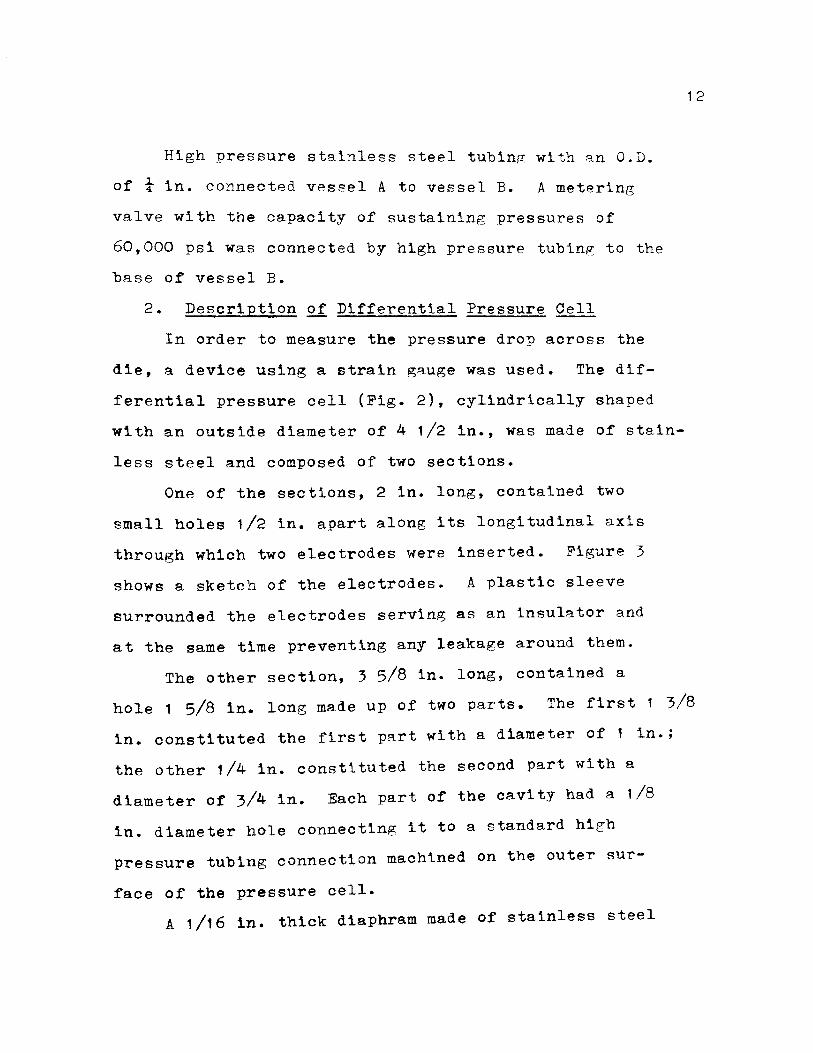
High pressure stainless steel tubing with qn O.D.
of i in. connected vessel A to vessel B. A metering
valve with the capacity of sustaining pressures of
60,000 psi was connected by high pressure tubing to the
base of vessel B.
2. Description of Differential Pressure Cell - --In order to measure the pressure drop across the
die, a device using a strain gauge was used. The dif
ferential pressure cell (Fig. 2), cylindrically shaped
with an outside diameter of 4 1/2 in., was made of stain
less steel and composed of two sections.
One of the sections, 2 in. long, contained two
small holes 1/2 in. apart along its longitudinal axis
through which two electrodes were inserted. Figure 3
shows a sketch of the electrodes. A plastic sleeve
surrounded the electrodes serving as an insulator and
at the same time preventing any leakage around them.
The other section, 3 5/8 in. long, contained a
12
hole 1 5/8 in. long made up of two parts. The first 1 3/8
in. constituted the first part with a diameter of 1 in.;
the other 1/4 in. constituted the second part with a
diameter of 3/4 in. Each part of the cavity had a 1/8
in. diameter hole connecting it to a standard high
pressure tubing connection machined on the outer sur-
face of the pressure cell.
A 1/16 in. thick diaphram made of stainless steel

..-- 8 -1 IN. B 0 L T S ...... t----1-------- ------1--1-~~---- ---~-J-~ ...._
..--
I I • I
'lr' '1 r' STD. HIGH PRESSURE ll I I •: n TUBING CONNECTIONS •• al I I II 1-,_- -J ... - -n t 1
' I .t-_J.L-, 1-------------- STRAIN 11 ' t---------------- II ELECTRODES GAUGE ;1 : 1-------------- I I r----- ...... ------- •• •r- --J
l r------..U
1--
...... ~------ ------~
t--1------ ------~ ......_ ......
FIGURE 2. DIFFERENTIAL PRESSURE CELL . ..._,.j

14
FIGURE 3. ELECTRODE
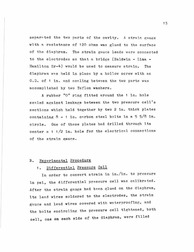
separ~ ted the two parts of the cavi ty . A s train ~~uge
with ~ resistance of 120 ohms was gl u ed to the surface
of the d i aphr a m. The strain gB.U !~ e leads were connected
to the electrod es so tha t a bridge (Baldwin - Lima -
Hamilton Sr - 4) would be used t o measure s train . The
d i aphram wa s held in place by a hollow screw with an
O.D . of 1 in . a nd sealing between t he two parts was
accomplished by two Teflon washers .
A rubb e r "O" r ing fitted a r ound the 1 in . hole
se8led against leakag e between t he two pressure cell's
sections which held together by two 2 in. thick plates
con taining 8 - 1 in . c~rbon steel b ol ts in a 5 5/8 in .
circle. One of these plates ha d dr illed t hrou!Sh its
center a 1 1/2 in. hole for the electric~l connections
of th e strain ~au~ e.
B. Ex p erimental Procedure
1 . Differential Pressure~
In order to convert strain in in . / in. to pressure
i n psi , the differential pressur e ce l l was calibr a ted .
After the strain gaug e had b een ~lued on the diaphr am ,
its lea d wires soldered to the electrodes, the str a in
gau~e a nd lea d wires covered with wa terpr oofing , and
the bolts encircling the pr P.s sure cell tigh tened, both
cell , one on each side of the diaphram, were filled
1 5

with hydraulic fluid. Since the holes lAadlng to these
cells were only 1/8 in. ln di~meter, a Ryringe with a
2 1/2 in. long needle WRS used to fill the cells with
fluid, thus ureventing any air from being trapped inside
the pressure cell.
To c~use the seating of the diaphram to be better
as the pressure differential increased, it was decided
to have the higher pressure on the cavity with the
lar~er diameter thus forcing the strain gauge to in
dicate compression instead of tension. This had no
particular effect other than make the strain gau~e a
little less sensitive.
The standard high pressure connection of the larger
diameter cell was connected to vessel A 8nd to a pressure
gaurre which read up to 1000 psi. The strain gauge tended
to drift somewhat when first used. In order to eltminate
the strain gau~e drift, it was pressurized to 1000 psi
several times until the strain gauge gave consistent
readings.
A Baldwin - Lima - Hamilton SR-4 strain indicator
was used to read strains. By controlling the rate at
which the Riehle Testing Machine was being driven,desired
pressures were attained for a pressure vs. strain call-
bra.tion curve. The pressure cell was calibrated from
0 - 1000 psi since the pressure drop across the die
occurred in this range.
1 6

1 7
After the pressure cell h~d been calibrnted, high
pressure tubing was connected from the other cell to the
base of vessel B thus giving a direct measure of the pres
sure drop across the die.
2. Rheometer
The polymer was loaded in vessel B directly above the
die. Quick loading was found to be the best way of pre
venting any air from being trapped in the polymer. A
small piston with a rubber "O" ring seal was placed directly
above the polymer to drive it evenly. After the polymer
had been loaded and the driving piston placed in its proper
position, the sections below the die and above the driving
piston were filled with hydraulic fluid. Since vessel B
weighed in excess of 100 lbs, a hoist was desi~ned to make
handling of vessel B easier.
To fill the section below the die with hydraulic
fluid, the vessel had to be inverted to prevent air from
being trapped. After vessel B had been filled at both ends
with fluid it was ready to be connected to the other pieces
of equipment. After vessel A and all of the connecting
tubing had been filled with hydraulic fluid by use of a
hand pump and all of the connections joined together, the
equipment was ready for use.
With the metering valve sli~htly open, the rheometer
was activated. By controlling the rate at which the piston
in vessel A was displaced and also by controlling the

setting on the metering valve, the de~ired pressure and
rate of extrusion were attained. The rate of polymer
extrusion was measured by measuring the rate of hydraulic
fluid displaced by the extrudate.
l 8
After equilibrium had been reached, the load on the
rheometer was read, the extrusion rate measured by findin~
with a stop watch the time required to extrude 0.2 cc of
polymer and the pressure drop across the die was read on
the strain indicator.
As soon as each experiment was completed, the bottom
of vessel B was disconnected and the extrudate removed.
A photograph of the polymer extruded was taken as a perma
nent record.
19
IV. DISCUSSION
A. Equipment Development
In developing the equipment for the study of polymer
extrusion at high hydrostatic pressure the biggest problems
arose in the design of the differential pressure cell and
in the system controlling the flow rate.
Since, a pressure gauge able to measure the pressure
drop across the die at pressures as high as 50,000 psi was
very expensive, a different method had to be found to
measure it. It was finally decided that a differential
pressure cell containing a diaphram upon which a strain gauge
was mounted would perform satisfactorily.
In the design of the pressure cell, the biggest concern
outside of safety was accuracy. The diaphram not only had
to be thick enough to prevent its deformation from exceeding
the elastic limit, but it also had to be thin enough to
give an easily measurable deflection. The equations used
in the design of the diaphram were (25):
f = (3P/16)(d/t)2
max f t t = ((1+M)d 2 )/(64(t2 /6))P a cen er /.
= Pd4 /1024D Ymax where:
f stress,psi.
P pressure, psi.
d diameter of diaphram, ln.
t = thickness of diaphram, in.
( 5)
( 6)
(7)
/A= Poisson's ratio
y = deflection of diaphram, in.
D flexural rigidity= Et3/12(1- 2)
E modulus of elasticity
The whole pressure cell including the diaphram was
made of stainless steel to nrevent corrosion. Since the
properties of the stainless steel were unknown, it wes
assumed that its modulus of el8sticity was 30 x 106 psi
and its modulus of rigidity 12 x 106 psi.
20
In securinF the str~in sau~e, which h8d a resistance
of 120 ohms, to the d iaphram, Ea_stman' s glue was used. In
order to prevent the hydraulic fluid from coming into
contact with the strain gau~e a waterproofin~ material
w~s spread on its surface. No matter how many layers of
waterproofing were used, however, it was impos~ible to
prevent the hydraulic fluid from gradu~lly changin~ the
strain gauge's response, a fact that went unnoticed
until all of the experimental data had been collected.
To solve this problem, it is proposed that the pres
sure cell be filled with mercury instead of hydraulic
fluid. With the strain gauge and its leads covered with
waterproofing, mercury could be used without any detri
mental effects. Because of mercury's high density,
there 1s no problem 1n ever having the hydrgul1c fluid
from coming into contact w1th the strain gauge.
In seal1ng the two sect1ons compos1ng the pressure

cell, a 0-type ring was first used. Because of the poor
results obtained a Viton "O" ring wqs later substituted
with excellent results.
The control of very small flow rates at high pres
sures was almost impossible with available high pressure
metering valves due to the tremendous pressure drop
across them. These valves were very errqtic in their
flow rate control behavior. At a p;iven valve setting
the flow rate tended to decreAse until it w8s non
existant even though the valve seemed to be clean And
21
the differential pressure across the valve was increasing.
It is proposed that a completely new flow control
system,one not usin~ any type of valve, be used. Since
after a certain pressure has been attained the rheometer
extrudes at a constant pressure (by fixing the back
hydrostatic pressure), a constant flow rate should be
att8.ined.
Using the principle of a dead load tester, a new
small diameter, hi~h pressure vessel (Fig. 4) containing
a piston with a platform on top for loading weights will
give a constant back pressure. By using the correct
load, the back pressure can be maintained at a constant
desired pressure. An "O'' ring on the piston should be
used to seal it against the cylinder wall. This system
would be filled with hydraulic fluid and attached to the
bottom of vessel B. The extrusion of the polymer will

22
w I l
PISTON
I I I I I I I I I I I I I I
I I I I I I I I I I I
: 0-RING
~==~GROOVE r--, I I I I
TO BOTTOM OF VESSEL B
FIGURE 4. FLOW RATE CONTROL VESSEL

cause the hydraulic fluid at the bottom of vessel B
to be displaced which in turn will cause the niston of
the new vessel to be pushed up. The rAte at which the
piston in the new vesRAl moves upward will give a means
of more accurately measurin~ the flow rate of the ex
trudate.
Because quite a bit of polymer had to be extruded
before equilibrium was reached, the extrudate many times
tended to get compacted in the lower section of vessel
B so as to lose its shape. This cRused wasted time in
reperforming experiments. A direct line containing a
valve from vessel A to the bottom of vessel B should
be used. During the loading process (pressure increase)
the upper and lower sections of vessel B will have
identical pressures. When the desired hydrostatic
pressure is ~ttained, the valve should be turned off and
the rate of extrusion adjusted by adjusting the rate at
which the rheometer is moving thus fixing the pressure
on the upper section of vessel B.
Alignment of vessel A with the rheometer must be
done with extreme care. Due in part to poor alignment
and to poor craftmanship in the machining of vessel A,
its piston galled the side of the cylinder when first
used. In designing vessel A, the hardness of the niston
and cylinder must not be the same, yet the piston and
cylinder are both made of very hard materials. A piece
23
of plywood or cardboard was placed under vessel A to
create a self-aligning system in case the vessel was not
initially perfectly aligned.
24
Another problem encountered was that of the hydraulic
fluid channeling through the polymer. The problem was
solved by the design of a small piston to push the polymer
into the die. An "O" ring on the piston prevented any
hydraulic fluid from being mixed with the polymer.
The problem of the oil softening the extrudate was
never satisfactorily solved. It is the opinion of this
investigator that the softening was caused by the hydraulic
fluid used to collect the extrudate in the section below
the die in vessel B, since no such effects were observed
in the extrusion of the polymer in air. This softening
effect tended to minimize extrudate distortions, a fact
which should be taken into consideration. Harder polymers
were sough in order to alleviate this problem, but the
General Electric SE-30 silicone gum is the best polymer
us e d so far.
Taking a good picture of the extrudate sample was
difficult because the polymer was transparent. The extrudate
sample was placed on a tracing table to be photographed
using a Polaroid camera with the shutter speed and f - stop
adjusted to get the best contrast . Best results were
obtained when the oil-wet extrudate was on a piece of
tissue paper, through which the light shone.

25
B. Experimental Results
Due to the problems mentioned in the previous section,
it was with extreme difficulty that data was obtained up
to a pressure of 4930 psi.
Extrusion without back pressure of the silicone gum
was done between a flow rate of 0.0312 cc/min. which
occurred at a pressure of 128 psi and a flow rate of 0.918
cc/min. which occurred at a pressure of 355 psi. It
should be noted that these pressures represent the pressure
drop across the die. It was not possible with the equipment
used to attain flow rates small enough to obtain a perfectly
smooth extrudate although at a flow rate of 0.0312 cc/min.
only minute ridges were visible. In the range of the flow
rates mentioned above, the distortion of the extrudate
went from minute ridges to screw thread like distortion
at a flow rate of 0.177 cc/min. and finally to a sausage
like appearance at a flow rate of 0.918 cc/min. (see Figs.
5,6,7).
Figs.(8,9,10) show the polymer extruded under high
hydrostatic pressures. The extrudate's diameter was over
twice as large as the 0.043 in. diameter of the die; die
swell was quite noticeable. Although the die swell seems
to be dependent on fluid flow rate (the lower the flow rate
the more noticeable die swell) no definit conclusions can
be drawn since there was not enough data and the data taken
was not consistent enough.

FIGURE 5. POLYMER EXTRUDED AT A PRESSURE OF 128 PSI. AND A FLQI RATE OF 0.0312 CC/MIN.
FIGURI 6. POLYMER EXTRUDED AT A PRESSURE OF 290 PSI. AND A. FI.Otl RATE OF 0.3)4 CC/MIN.
26
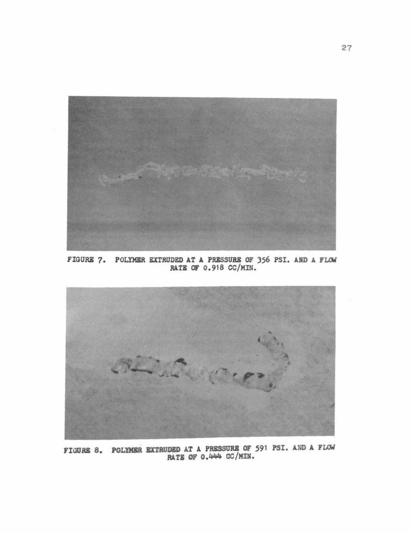
FIGURK 7. POLYMKR EXTRUDED AT A PR&SSURS OF )56 PSI. AND A. FLCW RATI OF 0.918 CC/MIN.
FIGURE 8. POLlMSR EXTRUDED A.T A PRESSURB OF .591 PSI. AND A FUM RATI OF 0.444 CC/MIN.
27

28
FIGURE 9. POLYMER EXTRUDED AT A. PRESSURE OF 2)70 PSI. AND A FLCitl RATE OF 0.444 CC/MIN.
FIGURE 10. POLYMER EXTRUD~ AT A. PRESSURE OF 2370 PSI. A.ND A. FLCM RATE OF O. 1 ~ CC/MIN.

Fig. (11) is a plot of die differential pressure {and
wall shear stress) versus flow rate (and shear rate) without
back pressure. The differential pressure for calculating
wall shear stress was taken to be the pressure on the
piston in vessel A. Wall shear rate was assumed to be
approximately 8U/D. This calculation neglects any elastic
entrance and exit effects on differential pressure and
assumes no plug flow, which is not necessarily true. This
figure shows that the polymer was a non-Newtonian fluid--
an expected result.
Because the hydraulic fluid tended to gradually detach
the strain gauge from the diaphram, a condition that was
not noticed until the experimental part of this study had
been completed, the differential pressures across the die
measured by the pressure cell will not be presented. Due
to this fact, increased viscosity at high hydrostatic pres
sure observed by others could not be confirmed.
At a hydrostatic pressure of 1000 psi. it was observed
that the piston in vessel A had a 7 psi drag stress. Since
this amounted to less than 1C of the total force, it was
neglected.
In the extrusion of silicone gum, with a hydrostatic
pressure, no melt fracture effects of pressure were noticed
by this observer. In all the runs using hydrostatic pres
sure, which ranged from about 450 psi to about 4700 psi,
a distinct melt fracture was noticed at approximately the
-(/) Q. -(/) (/) l1J a:
15
t; 10
a: <( UJ :r (/)
0
I 5--------~.--------·~~------~------~
200 400 600
0
SHEAR RATE CMIN.-I)
~0
FIGURE 11 . SHEAR RATE VS . SHEAR STRESS WITHOUT HYDROSTATIC PRESSURE

same flow rate (approximately 0.13 cc/min. or a shear
stress of 8.6 psi ).
Following is a list of pressures and flow rates
used in this experiment for the extrusion of silicone
gum SE-30.
)1

32
TABLE I
Results of the extrusion of SE-30 without hydrostatic
pressure:
Run Flow Rate Velocity Shear Shear p Die ( cc/min.) (em/min.) Rate Stress (psi.) Swell
(min.- 1 ) (psi.) Ratio
1 0.0312 0.334 24.5 5.50 128 2.4
2 0.0764 0.815 59.8 6.60 153 2. 1
3 0.177 1.89 139 9.72 226 screw
4 0.236 2.52 185 10.58 246 screw
5 0.434 4.64 340 12.46 290 screw
6 0.679 7.25 531 14.14 329 screw
7 0.918 9.80 720 15.30 356 sausage
33
TABLE II
Results o:f the extrusion of SE-30 using hydrostatic
pressure:
Run p Flow Rate Velocity Shear Die (psi.) ( cc/min.) (em/min.) Rate 1 Swell
(min.- ) Ratio
1 591 0.444 4.75 348 screw
2 591 0.124 1. 32 97 2.9
3 591 0.017 0.18 14 2.8
4 1185 0.500 5.?4 394 screw
5 1185 0. 116 1.24 92 2.5
6 1185 0.064 0.69 51 3.2
7 2370 0.444 4.75 348 screw
8 2370 0.134 1. 42 102 ?.0
9 2370 0.063 0.67 50 3.1
10 4930 0.119 1 .27 92 2.5
1 1 4930 0.444 4.75 348 screw
34
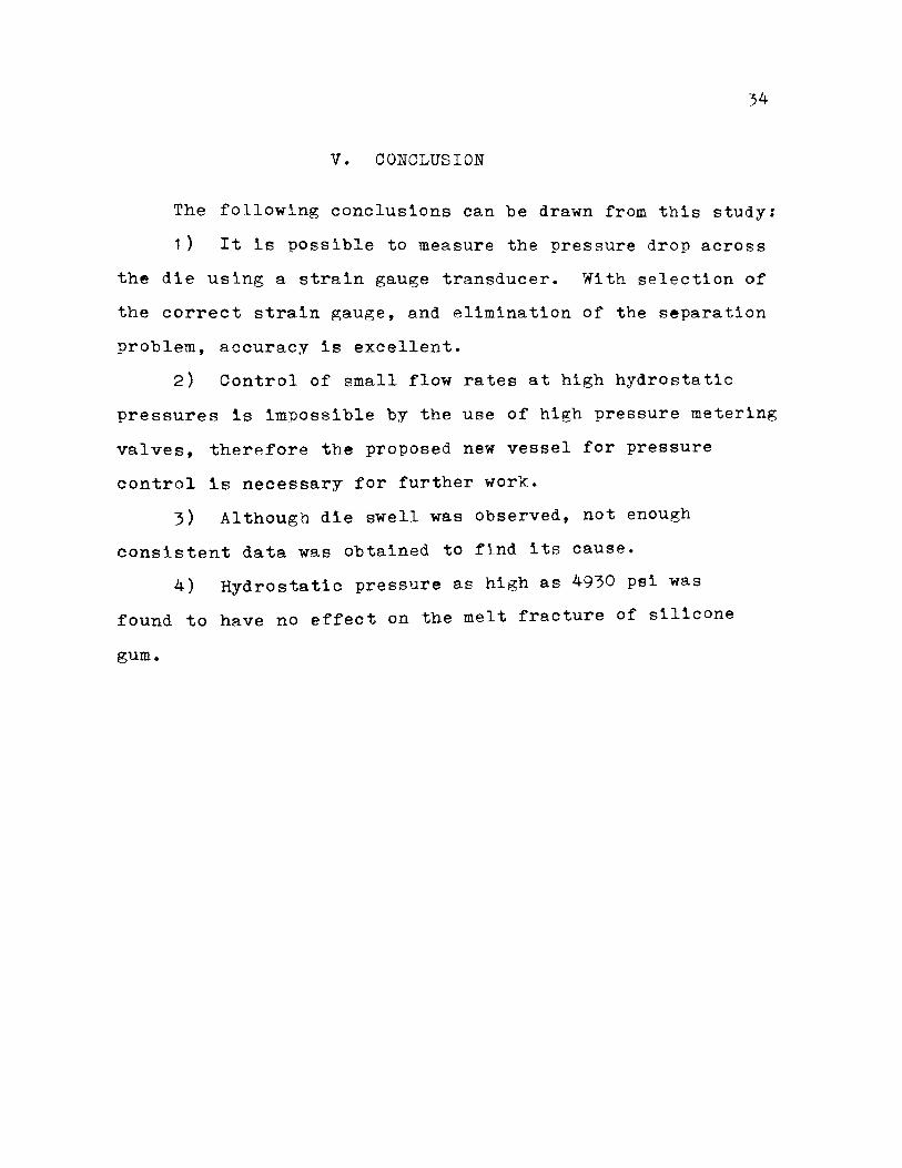
V. CONCLUSION
The following conclusions can be drawn from this study:
1) It is possible to measure the pressure drop across
the die using a strain gauge transducer. With selection of
the correct strain gauge, and elimination of the separation
problem, accuracy is excellent.
2) Control of small flow rates at high hydrostatic
pressures is impossible by the use of high pressure metering
valves, therefore the proposed new vessel for pressure
control is necessary for further work.
3) Although die swell was observed, not enough
consistent data was obtained to find its cause.
4) Hydrostatic pressure as high as 4930 psi was
found to have no effect on the melt fracture of silicone
gum.
1 •
2.
'· 4.
VI. BIBLIOGRAPHY
Pugh, H. Ll. D. and D. Green p I 415 (1965). ' roc •• Mech. E. 179,
Pugh, H. Ll. D., ASTM Special Tech. Publ. No. 374, 68 ( 1 964) • -- -
Billmeyer, F. W., Polymer Science. New York: Interscience, 1966.
Duvdevani, I. J. and I. Klein, SPE Journal 23, 41 (1967).
5. Rabinowitsch, B., z. Physik Chern. A 145, 1 (1929).
6. Tordella, J. P., J. Appl. Phys. gz, 454 (1956).
7. Bagley, E. B., J. Appl. Phys. 28, 624 (1957).
8. Metzner, A. B., E. L. Charley and I. K. Park, Mod. Plastics LL• 133 (1960).
9. Merz, E. H. and R. E. Colwell, ASTM Bull. 232, 63 ( 1958).
10. Sieglaff, C., SPE Trans.~. 129 (1964).
11. Spencer, R. s. and R. E. Dillon, J. Colloid Sci.~' 241 ( 1949).
12. Nason, H. K.' J. A:QJ21• Phys. 1.§., 338 ( 1945).
Tordella, J. p.' J. ApJ21• Phys. g:r, 454 ( 1956).
Tordella, J. p. ' Trans. Soc. Rheol. 1· 203 (1957).
35
1..,. 14.
1 5. Bagley, E. B. and H. P. Schereiber, Trans. Soc. Rheol • .2_, 203 ( 1 961 ) •
1 6.
17.
18.
Clegg, P. L., Rheology of Elastomers. edited by P. Mason, Pergamon, 1958.
Baeley, E. B. and A. M. Birks, J. Appl. Phys. 21· 556 ( 1960).
Bialas, G. A. and J. L. White, "Experimental Study of Capillary Flow and Extrudate Distortion", presented Division of Rubber Chemistry, ACS, September 1968.

36
19. Ballenger, T. F. and J. L. White, "Flow Patterns in Polymers Melts in the Reservoir of a Capillary Rheometer", presented A.I.Ch.E. Atlanta Meeting, February 1970.
20.
21 •
22.
23.
24.
25.
Bialas, G. A. and J. I •• White, "Site of Initiation and Mechanism of Melt Flow Instability", presented Division of Rubber Chemistry, .ACS, September 1968.
Matsuoka, S. and B. Maxwell, J. Poly. Sci. 32, 131 ( 1958).
Bradbury, E. J. and R. I. Leininger, ASTM Spec. Tech. Publ. No. 374, 22 (1964).
Westover, R. F., SPE Transactions l,i, January (1961 ).
Maxwellt B. and A. Jung, Modern Plastics, 274 November (1957J.
Brownell and Young, Process Equipment Design. New York: Wiley, 1959.

VII. VITA
Edward Moniz Jorge, son of Jose M. Jorge and Maria
H. Jorge , was born on July 16, 1944, in Horta, Azores .
37
He attended elementary school in Horta, Azores. He
graduated from James Logan High School in Union City,
California in June 1963. He enrolled at San Jose State
College in 1963 and r eceived a B.S. degree in Chemical
Engineering in June 1968 . In September 1968 he entered
the Graduate School of the University of Missouri at Rolla .
183318