design considerations when implementing motor control...
TRANSCRIPT

Design Considerations when Implementing Motor Control Technology
Benefits and design challenges of implementing stepper, BLDC, and Brushed motor control technologies in the 5 W – 100 W power range as well as how to
transition from brushed to brushless technology

Electric Motor Type Classification
Electric Motors
AC Motor DC Motor
Polyphase Single
Phase
Synchronous
Squirrel
cage
Wound
Rotor
Squirrel
cage
Cap
Run
Cap
Start
Perman
ent Split
Cap
Variable
reluctan
ce
Shaded
Pole
Split
Phase
Asynchronous
BLDCStepper Relucta
nce
Sine
Wave
Variable
Reluctance
Hybrid
PM
Wound
Rotor
Sync
Conden
ser
PM
Rotor
Switched
Reluctance
SYNC
Reluctance
Brush
DC
Commu
tator
Homop
olar
Wound
Field
PM
Shunt SeriesCompo
und

Motor Comparison
Stepper Motors Brush DC Motors BLDC Motors
Reliability OK Low Excellent
Power Density Bad Good Excellent
Efficiency Ghastly OK Good
Precision Very Good OK Depends
Cost Motor Low Cheap High
Cost Electronics OK Cheap High
Stepper Motor DC Motor EC Motor
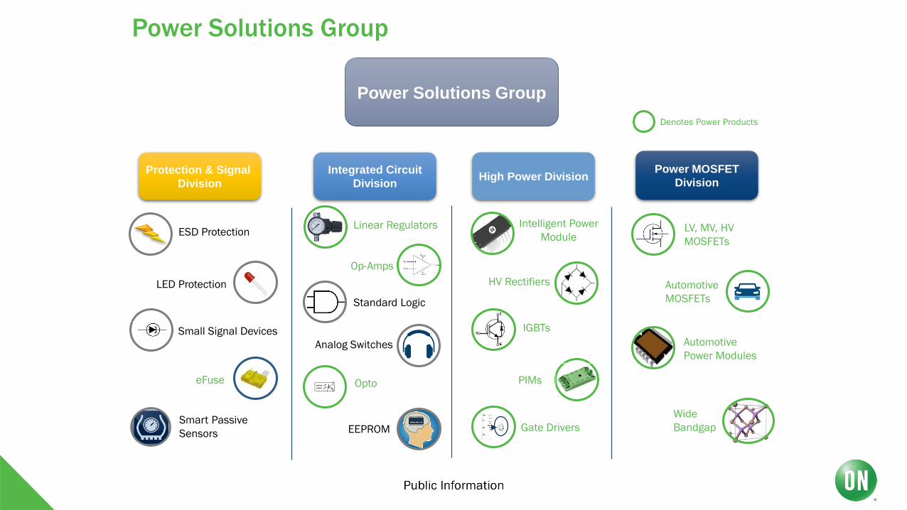
Power Solutions Group
Protection & Signal
Division
Integrated Circuit
Division
Power MOSFET
Division
ESD Protection
LED Protection
Small Signal Devices
eFuse
Smart Passive
Sensors
Intelligent Power
Module
IGBTs
HV Rectifiers
PIMs
Power Solutions Group
LV, MV, HV
MOSFETs
Automotive
MOSFETs
Wide
Bandgap
Automotive
Power Modules
High Power Division
Linear Regulators
Op-Amps
Standard Logic
Analog Switches
EEPROM
Opto
Denotes Power Products
Gate Drivers

MOTORS in a nutshell…
Almost 99% guarantee it was a Motor
Failure due to Control issues
1. All of the Controls are driven by Motor or
Inductive Actuator of sorts
2. Steering
3. Braking
4. Accelerator
5. Shifting
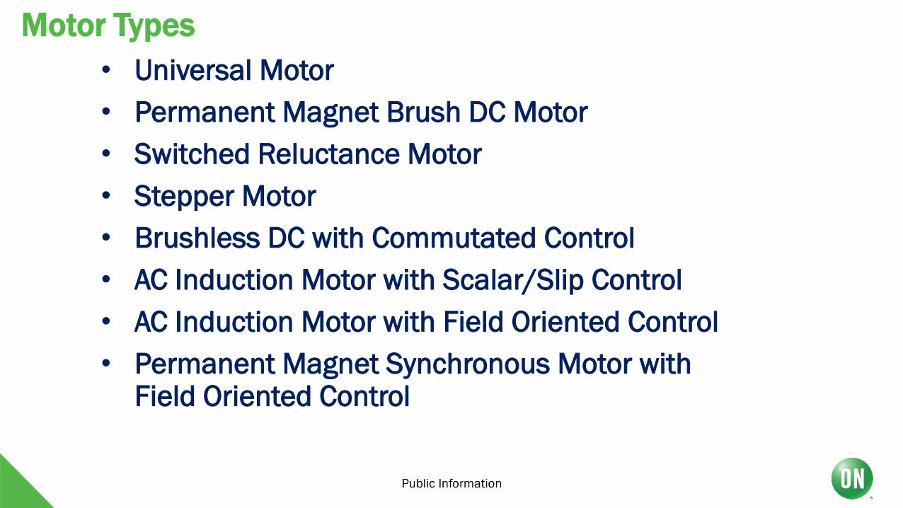
• Universal Motor
• Permanent Magnet Brush DC Motor
• Switched Reluctance Motor
• Stepper Motor
• Brushless DC with Commutated Control
• AC Induction Motor with Scalar/Slip Control
• AC Induction Motor with Field Oriented Control
• Permanent Magnet Synchronous Motor with Field Oriented Control
Motor Types

HomeRefrigerator Compressors
Washers/Dryers
Exercise Equipment
Small Appliances / Hand tools
Computers / Office Equipment
HVACAir Conditioning Compressors
Pumps / Fans / Blowers
Building Automation / Regenerative Systems
IndustrialConveyor Systems
Industrial Drives
Industrial Servo/ CNC / Robotic Assembly / Pick and Place
Motor Markets & Applications
Transportation
Automotive Body
Electric Power Steering
Automotive PowerTrain
Hybrid-Electric Vehicles
Personal Transport
Medical
Medical Pumps
CPAP
Medical Scanners

PMDC-to-BLDC Pros
• No Mechanical Brushes - Lower Maintenance, Lower Radiated EMI, Higher Reliability, Improved Compatibility with Bi-Directional Applications
• Torque Ripple - BLDC offers more control over torque ripple via which algorithms are implemented.
• Acoustic Noise - BLDC has the ability to rotate in a virtual silence, depending on the motor-winding pattern, sensing, and modulation scheme.
• Speed Control - PMDC motor speed control(assuming no encoder) is typically done by measuring the BEMF of the motor winding. To significantly improve the accuracy of the estimated speed, IR(current-resistance) compensation is implemented to make up for errors due to winding losses. The total accuracy of the speed control in this case is functional, but poor. BLDC motors with Hall sensors can very accurately use this information to know precise speed. BLDC motors without Hall sensors can accurately measure speed based on the feedback signals(current or voltage) used by their sensorless algorithms.
• Position Control - Without an encoder, PMDC controls have no way to understand the position of the shaft w.r.t. the rotor nor w.r.t. any application reference. BLDC motors with Hall sensor can use the Halls for additional position control purposes. BLDC motors without Hall sensors can sometimes use current or voltage feedback signals to accurately provide position information, depending on the algorithm implemented.
6/7/20198
PMDC-to-BLDC Pros (Part 2)
• Torque Control - BLDC and PMDC have very similar speed-torque curve shapes and similar
torque-producing capabilities. As current increases, BLDC has the advantage of improved lifetime. Torque is proportional to current.
• Speed Range - BLDC can operate at very high speeds without sacrificing
reliability. Although there are some high-speed PMDC motors, they are usually implemented due to decreased cost; and not because they are more reliable. To operate BLDC at high commutation rates requires some faster processing and careful algorithm selection.
• Because PMDC motors have fixed commutator ring transitions, their magnetics
and commutation cannot be optimized for various applications. BLDC motors are often dynamically tuned in the electronic control to operate at higher efficiencies, and to use the motor materials more effectively thereby reducing motor material cost. Today, there are very few applications where PMDC motors are the better choice over BLDC.
• Environmental Compatibility - PMDC motors are considered unacceptable and dangerous for applications where open sparks(from the brushes) can cause explosion or contamination issues. BLDC motors have no electrical sparking or similar molecular breakdown of materials while rotating. BLDC motors can even be designed to operate submersed in liquid
6/7/20199

PMDC-to-BLDC Cons
• BLDC and its cousins(PMSM, BLAC, PMAC) all require electronic controls to successfully rotate the motor - Technically, PMDC motors can spin simply by being
connected to a DC power source with zero control electronics. For PMDC motors to spin as a predictable speed or torque, electronics are required.
• Uni-directional PMDC applications are often implemented in their power bridge with a
single low-side transistor. Uni-directional BLDC controls always require 6 transistors. Be aware that the increase in BLDC control cost is often completely offset by the improved system cost of the motor and other materials. i.e. heat sink.
• Bi-directional PMDC applications are often implemented in their power bridge with 4
transistors(H-Bridge). Bi-directional BLDC controls still require the same 6 transistors. Be aware that the increase in BLDC control cost is often completely offset by the improved system cost of the motor and other materials. i.e. heat sink.
6/7/201910

BLDC Motor Drive Generic Block Diagram
6/7/201911
PMDC: 3-phase:
Quiet: Moderate Excellent
Efficiency: Good Excellent
PMDC

Motor Type Comparison
6/7/201912
Feature: BLDC Motor: Brushed Motor: BLDC Advantages:
Commutation Electronic commutation based on
rotor position information
Mechanical Brushes and commutator Transistors replace mechanical brushes
Efficiency High Moderate Transistors based drives operate very efficintly
Maintenance Little/none Periodic No brushes/commutator maintenance
Thermal Performance Better Poor Only the armature windings generate heat, which is the
stator and is connected to the outside case of the
BLDC. The case dissipates heat better than the rotor
located inside of the brushed DC motor.
Power Density: Output Power / Frame
Size (Ratio)
High Moderate/Low Modern permanent magnet and no rotor losses.
Speed /Torque Characteristics Flat Flat No brush friction to reduce useful torque.
Dynamic Response Fast Slow Lower rotor inertia because of permanent magnets.
Speed Range High Low No mechanical limitation imposed by brushes or
commutator.
Electric Noise Low High No arcs from brushes to generate noise, causing EMI
issues.
Lifetime Long Moderate No brushes and commutator

BLDC Three-phase Commutation Sequence w/ Hall Effect
6/7/201913
Hall (a, b, c) Input decoded to a lookup table for FET Control
and Commutation Sequencing (Trapezoid) every 600
electrical, 300 mechanical rotation.
Hall Sensor: 1200 Phase Shift
Step 1:
Step 2:
Step 3: Step 4:
Step 5:
Step 6:
Commutation Steps 1 - 6:

Trapezoidal vs. Sinusoidal Commutation
6/7/201914
Sinusoidal:
1) Finer (smoother) resolution commutation
a) improves torque ripple.
b) reduces acoustic noise
2) More complicated control.
Trapezoidal references a lookup table for
each Hall Sensor Change (rotor angle), or
every 600 (electrical cycle).
Sinusoidal generates (algorithm) a
continuous, higher resolution, series of
steps.
U is High Side, X is Low Side for U Stator Winding
V is High Side, Y is Low Side for V Stator Winding
W is High Side, Z is Low Side for W Stator Winding

PSG PSG/ASGASG
AC IN
MCU
Power Factor Correction
Input Bridge Rectification
EMI Filter
Inve
rte
r
Isolated Gate Driver
Regulator
No Solution
MotorAux
Power Supply
Current Sense
IsolatedGate
Driver
Industrial Motor – ON offers a Complete BOM Coverage
High efficiency
FS4 650V &
UFS 1200 IGBTs
High precision
Current Sense Amps
Performance LDOs
Smart Opto-
coupler /
Gate Drivers
High efficiency
SuperFET III
650V FETS
Gel-filled &
Transfer Molded
Modules
2014 2016 2017
• FS3 IGBT
• IPM
• LV/MV FET
• LDO
• Op-Amp
• Rectifier
• Small Signal
• UFS 1200V IGBT
• Vincotech PIM
Packages
• High Perf.
Analog
• GaN
• HV Gate Driver
• FS4 650V IGBT
• IFX PIM Packages
• SuperFET up to 800V
• Opto-Coupler
• Opto Gate Driver (4A)
• SiC

3-Phase
6/7/201917
Motors – Controllers and Drivers

MOTOR SIZING DESIGN CONSIDERATIONS
What Motor to use?

MOTOR Technical Specifications (Boilerplate)
Customer Name/Region General Applcaition intel Motor Type-BLDC/Brushed/Stepper/AC COMMENTS
Definitions Specifications units Tech-Specs
1 Rated Capacity W
2 Input Votlage V
3 Rated Current (MIN/MAX) A
4 Starting Current A
5 Overcurrent Limt A
6 Speed Range RPM
7 MAX Speed @ MAX Voltage Wnl
8 Rated Torque Kt
9 Rated Voltage Kv
10 Overvotlage Limit V
11 Motor Feedback
12 Commutation Trajectory Shape
13 Mode of Operation
14 Fatures
15 Input Signal
16 Display Functions
17 Operating Temp/Humidity Deg C/%
18 Vibration Levels Hz - AdB/Octave Level
19 Airborne noise dbA
20 Approx Size HxWxD
21 Cooling for Driver/Inverter Air/Water/Forced
22 Miscll
23 Motor Poles Number
24 Load infomration Gearhead/Linear/Rotational
25 Operating Frequency of Driver/Inv Hz
Specifications for Motor Controller/Driver

MOTOR SIZING DESIGN CONSIDERATIONS
Power Source -AC (120V, 220V…), -DC (batteries, etc)
Torque Requirements (Power)
-Constant Torque (Torque depends on RPM’s. Many manufacturers list motors by power (hp) rather than torque for a given RPM)
-Variable Torque
-Stall torque characteristics
RPM Requirements
-Built in gear reduction (AC or DC gear motors)
-External gear reduction (Will a gear reduction be incorporated after the motor output in the design or will the motor need to supply a certain RPM)
Controls
*How will the motor be controlled? To what extent will control be an issue? This really needs to be addressed before a motor is selected.
Positioning during Rotation
-Precision
-Braking
-Reversibility (rotation in both directions?)
Operating Environment
- Temperature
- Chemical
Physical size / Mounting position
- length
- diameter
Certain design parameters should be considered while selecting a motor. Depending on the application, different combinations of parameters will determine which
motor(s) are suitable. Below is a checklist of parameters to consider while selecting a motor. Not all parameters will be constraints but particular care should be given to
identifying constraints and conveniences.

Helpful Generalizations
If speed control is needed remember DC are much easier. (AC motors require frequency control instead of voltage control.)
Is it single phase or 3 phase? You really don’t have a choice…ask the customer which is appropriate.
DC induction motors will stall at higher RPM’s where industrial will maintain torque through until stall torque is reached (think of a cordless drill.) Look at the manufacturer’s torque curves.
Careful with gear motors… is the torque given by the manufacturer the actual output torque after gear reductions?
If precision stopping control is needed consider which is more appropriate:
-Stepper Motors
-Servo Motors
* Servo motors actually have to sense position of the motor and control accordingly. Stepper motors may be open loop because they move to specified angles (i.e. in 3 degree increments) but there is no way to sense if it actually stopped at the desired position. Overloading a stepper motor may cause it to not arrive at the desired position and there would be no way to sense that.

Brush DC Motor
Description of Brush DC Motors:
In order for any DC motor to operate, the current to the motor
coils must be continually switched relative to the field
magnets. In a brush type unit, this is accomplished with
carbon brushes contacting a slotted commutator cylinder
which has each motor coil connected to a corresponding bar
of the commutator. The switching
continues as the motor rotates. With this arrangement, there
are physical limitations to speed and life because of brush
wear. Speed depends on amount of voltage applied.
Typical Use of Brush DC Motors:
•Variable speed applications (like all DC motors)
•Applications with simple controls
Figure 1
Figure 2
Advantage Over Brushless DC Motors:
•Cheaper (generally)
•Stand alone: requires no sensing (driver)
•Requires no controller
•Speed control is easier (via changing voltage only)

Brushless DC MotorDescription and Comparison to Brush Motors:
The main difference between Brushless and Brush concepts is the means of
commutating the motor coils. In a BLDC motor, the position of the rotor is
sensed and continually fed back to the commutation electronics to provide for
appropriate switching.
Advantages of Brushless DC Motors:
Since there are no carbon brushes to wear out, a BLDC motor can provide significantly greater life being now only limited by
bearing wear. BLDC motors also offer additional advantages as by-products of the inherent construction:
1. Higher efficiencies
2. High torque to inertia ratios
3. Greater speed capabilities
4. Lower audible noise *As compared to Brush DC Motors
5. Better thermal efficiencies
6. Lower EMI characteristics
In a BLDC system, the coil windings are typically stationary, while the field magnets are part of the inner rotating member.
This allows the heat generated in the windings to be transferred directly to the motor housing and any adjacent heat sinks,
thus providing cooler operation. The temperature rise per watt (TPR) is typically less than a brush type motor of comparable
size. Since the field magnets are on the inner rotor, the inertia is less than brush type motors, thus providing faster
acceleration rates for the BLDC unit. Brushless DC motors can operate in a wide variety of environmental conditions while
still providing the linear speed torque characteristics found in brush motors.
Notes on Brushless DC Motors:
•Require some sort of driver (sensing)
•Some sort of controls are needed

AC Motors
General AC Motor Description:
An AC motor has two basic electrical parts: a "stator" and a "rotor" as shown in Figure 6. The stator is in the
stationary electrical component. It consists of a group of individual electro-magnets arranged in such a way that
they form a hollow cylinder, with one pole of each magnet facing toward the center of the group. The rotor also
consists of a group of electro-magnets arranged around a cylinder, with the poles facing toward the stator poles.
We progressively change the polarity of the stator poles in such a way that their combined magnetic field rotates,
then the rotor will follow and rotate with the magnetic field of the stator.
Single Phase AC
Single phase AC motors utilize single phase AC
electricity.
Uses:
Residential or areas where only single phase
wiring is available. Good performance up to 1.0
hp; can use 110V up to nearly 5 hp. Also, some
are available for 220V single phase.
Three Phase AC
Three phase AC motors utilize three phase AC
electricity (that must be wired in the outlet)
Uses:
Industrial or areas with appropriate wiring.
Advantages:
•Uses 1/3 the amount of current (increased
efficiency)
•More easily reversed
•Huge power capabilities

Universal Motors General Description:
Universal or series motors are those having brushes, a wound rotor, and a wound stator. They are compatible with both AC and DC power. They are also distinguished by their noisiness. These motors produce so much noise because the brushes rub on the slotted armature.
Uses:
Manufacturers use universal motors because they are smaller and much lighter than induction motors. An example of this type is that found in a portable drill or a Dremel tool.
Basically the DC motor characteristics that can be run on AC.
Comparison to Induction Motors:
A 3/4 Hp induction motor...runs at 1075 - 3450 RPM, is about 6" long x 6" diameter and weighs about 19 pounds. If we compare this with a universal motor with 3/4 horsepower output, we see a speed increase of about 15,000 RPM, a size reduction to about 6" long x 3" diameter 1/4 of the volume and a weight reduction of greater than 85%.
Advantage
The weight difference is huge: Universal motors are much lighter than induction motors
Torque goes clear down to stall torque (DC motors will stall at a high RPM)
Lower cost
Variable speeds
Disadvantage:
Non reversible (one direction)
Noisy

Linear Motors
Linear Motor Technology
The same electromagnetic force that produces torque in a rotary motor also produces direct force in a linear motor. For example, a
permanent magnet DC linear motor is similar to a permanent magnet DC rotary motor and an AC induction linear motor is similar to
a squirrel cage induction motor.
Take a rotary motor, split it radially along its axis of rotation and flatten it out. The result is a flat linear motor that produces direct
linear force instead of torque. Linear motors utilize the same controls as rotary motors. And similar to a rotary motor with rotary
encoders, linear motor positioning is provided by a linear encoder. A variation of the linear motor is the tubular linear motor. This
design rolls up the motor about an axis parallel to its length. This results in a “non-commutated” motor.
Uses for Linear Motors:
•Linear applications (lower precision)
Features of Linear Motors
• High accelerations – up to 10 g’s [98 m/s]
• Small, compact – fits into smaller spaces
• No backlash from gears or slippage from belts – provides smooth operation
• Reliability – non-contact operation reduces component wear and reduces maintenance
• Linear motor output is measured in Lbs. [N] of force or thrust.
• Linear motors provide force to 2000 Lbs. [8900N], and speeds to 200 in/sec [5 m/s] depending upon encoder resolution.
• Higher speeds are possible with special controls
• Unlimited strokes from 0.01 in [0.000254m]
• Submicron positioning when coupled with an
appropriate feedback element and bearing system.
• Designs are available with either a moving coil or moving magnets.
Stepper Motors
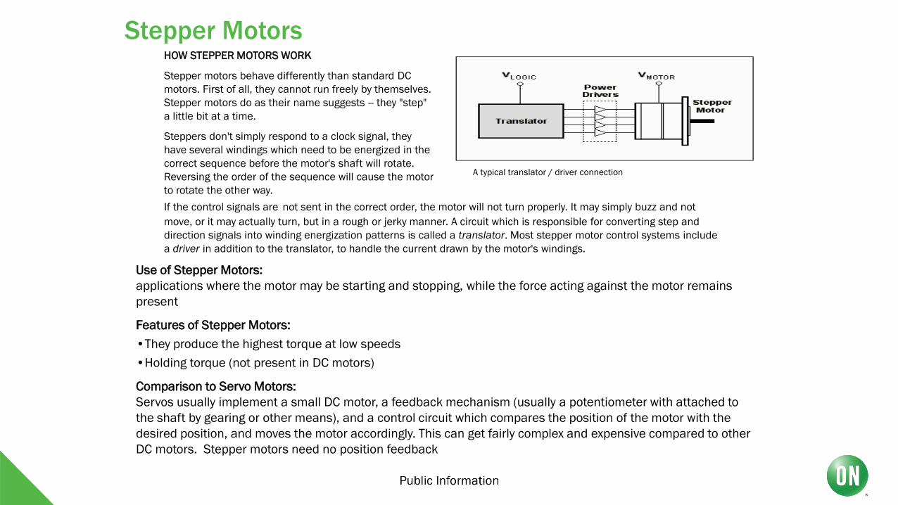
A typical translator / driver connection
HOW STEPPER MOTORS WORK
Stepper motors behave differently than standard DC
motors. First of all, they cannot run freely by themselves.
Stepper motors do as their name suggests -- they "step"
a little bit at a time.
Steppers don't simply respond to a clock signal, they
have several windings which need to be energized in the
correct sequence before the motor's shaft will rotate.
Reversing the order of the sequence will cause the motor
to rotate the other way.
Use of Stepper Motors:
applications where the motor may be starting and stopping, while the force acting against the motor remains
present
Features of Stepper Motors:
•They produce the highest torque at low speeds
•Holding torque (not present in DC motors)
Comparison to Servo Motors:
Servos usually implement a small DC motor, a feedback mechanism (usually a potentiometer with attached to
the shaft by gearing or other means), and a control circuit which compares the position of the motor with the
desired position, and moves the motor accordingly. This can get fairly complex and expensive compared to other
DC motors. Stepper motors need no position feedback
If the control signals are not sent in the correct order, the motor will not turn properly. It may simply buzz and not
move, or it may actually turn, but in a rough or jerky manner. A circuit which is responsible for converting step and
direction signals into winding energization patterns is called a translator. Most stepper motor control systems include
a driver in addition to the translator, to handle the current drawn by the motor's windings.
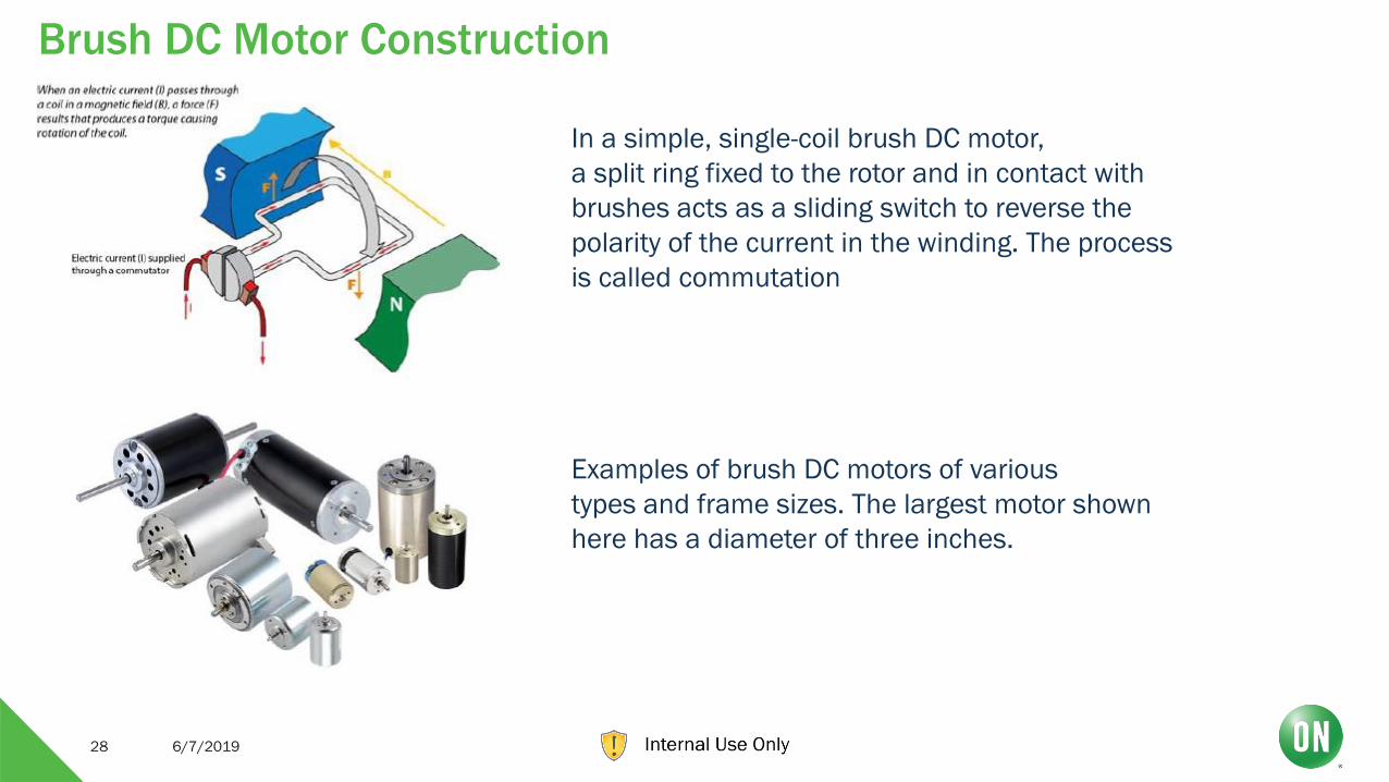
Brush DC Motor Construction
6/7/201928
Examples of brush DC motors of various
types and frame sizes. The largest motor shown
here has a diameter of three inches.
In a simple, single-coil brush DC motor,
a split ring fixed to the rotor and in contact with
brushes acts as a sliding switch to reverse the
polarity of the current in the winding. The process
is called commutation

Brushless DC (BLDC) Motor Construction
6/7/201929
In a three-phase BLDC motor, the stator
has three separate coils that are displaced from
one another by 120 electrical degrees
In a BLDC motor, the magnets (blue and
green) are on the rotor and the windings (copper)
are on the stator. This improves heat transfer,
thereby enabling higher performance than brush
motors of equivalent size. The motor shown in
this diagram uses Hall-effect sensors to
determine rotor position

Driving Motors (BLDC) Made Simple
System MCU
(optional)Controller/Pre-
driver
Gate
Driver
“Motor Controller”
Command Center
Pre-driver converts MCU
commands into motor drive
waveforms (commutation)
Most intelligent part of motor drive
system
Power to motor
is Optional,
depending on Power
Switches Gate Drive
capability
“Power Stage”
Most important part of the
Motor Drive System.
Usually consists of IGBT’s or
MOSFET’s, depending on
power level
“Gate Driver”

The two main choices for power-switching elements for motor drives are the & ON Semi has very wide MOSFET and IGBT Portfolio
Challenge – Is to create and select best suited Power Devices and Feedback for a given Motor Driver application
To Keep in Mind -
• IGBTs and HV MOSFETs are similar in many ways but differ from a performance and application perspective
• A one size fits all approach does not work
• The best device is the one that best meets the application needs in terms of size, efficiency and Amps/$ capability..!
Power Switches for Motor Drive Apps are MOSFET and IGBT WHAT’S BEST FOR YOUR APPLICATION?

MOSFETs – Any Size, Any Package
TO-3P TO-247 TO-220 D2PAK DPAK SO-8 TO-LL 8x8SO8
DFN
SO8
LFPAK
$2
B 25V
30V$
2B
TA
M
40V
60V
80V
100V
150V
250V
$1
B T
AM
600V
800V
900V
1.5kV
1.7 kV
SO8FL & u8FL = ON & FCS, LFPAK = NXP

IGBTs – Now a Premier IGBT Supplier
TO-3P TO-247 TO-247 4L TO-220TO-220
FullPakD2PAK DPAK
600V
650V
1200V
1350V
1500V
1600V
650V 1200V
650V FS4
exceeding IFX H5
Performance
1200V UFS
exceeding IFX H3
Performance

ON Semi MOSFETS – 20 V – 1500 V in Application with Optimized Process
• Low Voltage Family optimized for Qgd x Rds(on)
• Separate family optimized for pure Rds(on) performance
• 600 V – 700 V Super Junction MOSFET for Motor Driver + SMPS
ON Semi IGBTS – 300 V – 1500 V Discrete Devices
• Class-leading turn-off loss
• High-speed, short-circuit rated, and low
• Vce(on) optimized using thin wafers
• Multiple package options and bare die option available
Discrete and Integrated Power Products

Broad Line of Packages and Devices
Current ratings from 0.8A to 30A rms
Voltage ratings from 600V to 1500V
Junction temperature to 175°C
WBG – SiC, Fast Recovery & GaN
SiC Schottky barrier diodes for very high switching speeds
3A to 30A, 600V – 1200 V GaN parts available
SBD optimized for high switching speeds
Discrete and Integrated Power Products

BLDC H-Bridge Gate Driver Portfolio
6/7/201936
VM
(V
):
180V
24V
180V
24V
VM
(m
ax)
:
Gate (Source/Sink) Drive (A):
1A 2A 3A 4A
1 Half-Bridge Driver; Rise/Fall (1nF)
3 Half-Bridge Driver; Rise/Fall (1nF)
600V 600V
250mA
Built in UVLO*
* FAN739025ns (4.5A) / 20ns (4.5A)
* NCP81075
8ns (4A) / 7ns (4A)
FAN326812ns (1.6A) / 9ns (2.4A)
* FAN7393340ns (2.5A) / 20ns (2.5A)
* FAN7388/ * FAN7389450ns (350mA) / 30ns (650mA)
* FAN738450ns (250mA) / 30ns (500mA)
* FAN788850ns (350mA) / 30ns (650mA)
* NCP8108019ns (500mA) / 17ns (800mA)

When to Use Summary: Conditions Based
IGBT
Preferred..!
Low Switching Frequency (<20kHz)
High Power levels (above say 3 kW)
High dv/dt needed to be handled by the
diode
Med full load Efficiency is needed
MOSFET
Preferred..!
High Switching Frequency (>50kHz)
Lower Power levels (below 3 kW)
High dv/dt needed to be handled by the
diode
High full load Efficiency is needed
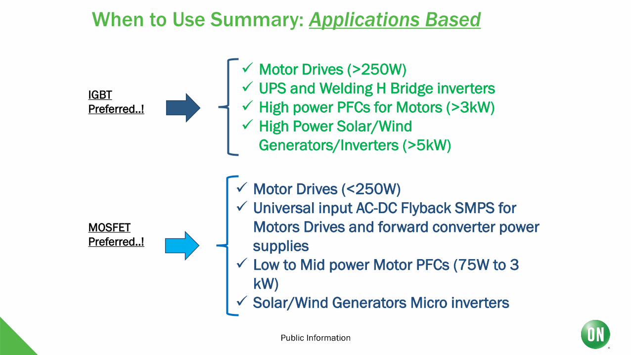
When to Use Summary: Applications Based
IGBT
Preferred..!
Motor Drives (>250W)
UPS and Welding H Bridge inverters
High power PFCs for Motors (>3kW)
High Power Solar/Wind
Generators/Inverters (>5kW)
MOSFET
Preferred..!
Motor Drives (<250W)
Universal input AC-DC Flyback SMPS for
Motors Drives and forward converter power
supplies
Low to Mid power Motor PFCs (75W to 3
kW)
Solar/Wind Generators Micro inverters

The Motor PFC Stage: IGBT or SJ-MOSFET
Application Conditions Device RequirementsTypical Power Range is 1 kW to 4
kW
High average currents, large
die/package devices
Typical Switching Frequency : 25
kHz to 150 kHz
At lower levels IGBTs, at
higher levels MOSFETs
preferred
Typically Devices are Hard
switched
Fast switching capabilities
essential
Typically lower inductor current
rippleLess stressful for the device
Some Key Application Conditions and Device Requirements
CCM (Continuos
Conduction Mode)
Topologies
Application Conditions Device Requirements
Typical Power Range is 100 W to 1
kW
Relatively smaller
die/package devices could be
considered
Typical Switching Frequency range
is wide (50 kHz to 300 kHz)
Almost always MOSFETs are
used
Typically Devices are Soft switched
at turn on and hard switched turn
off
Low Rdson is as important as
gate charge
Typically higher inductor current
ripple MMore stressful for the device
CRM (Critical Conduction
Mode) Topologies

The Motor Driver Stage: IGBT or FET
IGBT (with FRD) or HV FET
75 W to 200W Fast Body Diode FET preferred
500 W to 5 kW IGBT is preferred
200 W to 500 WCould be either, based on cost,
target efficiency, etc.
Few kHz to say 25 kHz IGBT is generally preferred
Above say 25 kHz
Also depends on power level, but
a Fast body diode FET may be
preferred
Application Conditions/Requerments
Power
Level
PWM
Frequency
Some Key Application Conditions and Device Requirements
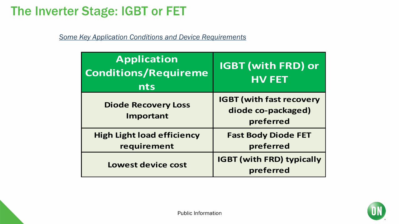
The Inverter Stage: IGBT or FET
Application
Conditions/Requireme
nts
IGBT (with FRD) or
HV FET
Diode Recovery Loss
Important
IGBT (with fast recovery
diode co-packaged)
preferred
High Light load efficiency
requirement
Fast Body Diode FET
preferred
Lowest device costIGBT (with FRD) typically
preferred
Some Key Application Conditions and Device Requirements

Total Gate Charge (Qg)
Generally higher for HV MOSFETs (larger die compared to IGBT, for same current rating)
Turn on gate resistors
Generally higher values used for IGBT (lower input capacitance compared to HV MOSFETs)
Gate Drive Voltage
Higher (15 V) preferred for IGBT, 10 V is ok for HV MOSFETs
Negative Gate Drive Voltage
Generally not needed for HV MOSFETs, sometimes used for older process IGBTs
Gate Drive Requirements and Considerations

3-PH BLDC Gate Driver/FET Guidance, 1st Order Approximation
1st Order Approximation Considerations:1. 850C Max Ambient Temp.
2. Matching Gate Drive Strength to FET Input Capacitance.
3. FET Power Dissipation = 500C below max operating die temp
4. FET Voltage = 2-3x Motor Voltage.
Motor
HP:
Power: DC Rail
(VM):
Gate Driver: N-Channel
Family:
N-FET Examples: RdsonMax @
VGS =10V
N-FET Package:
1/8 93W12V
FAN7888 (1x)
NCP81080 (3x)
Trench 6NTTFS5C466NL (40V) 7.3mΩ
3.3 x 3.3mm1/4 186W
24V
NTTFS5C673NL (60V) 9.3mΩ
MV7 FDMC86340ET80 (80V) 6.5mΩ
1/2 372W
FAN73933 (3x)
Trench 6 NTTFS5C573NL (60V)6.5mΩ
MV7 FDMC86340ET80 (80V)
3/4 559WTrench 6 NTMFS5C646NL (60V) 4.7mΩ
5 x 6mm
Trench 8 NTMFS6H824N (80V) 4.5mΩ
1 745W
NCP81075 (3x)
FAN7390 (3x)
Trench 6 NTMFS5C628NL (60V) 2.4mΩ
Trench 8 NTMFS6H801N (80V) 2.8mΩ
1 1/4 931WTrench 6 NTMFS5C604NL (60V) 1.2mΩ
Trench 8 NTMFS6H800N (80V) 1.9mΩ
1 1/2 1,117WTrench 6 NTMFS5C604NL (60V) 1.2mΩ
MV7 FDMT80080DC (80V) 1.35mΩ 8x8mm Dual Cool w/ Heat Sink

Choosing Between Brush and Brushless DC Motors
BRUSH DC MOTOR PROS
1. Simple
2. Rugged
3. Low Cost
4. Do not require complex/expensive Control for Commutation
5. Can work directly from DC Supply via Resistor or Potentiometer to control speed
6. Can have simple control added to create Servo Based Motor for greater accuracy at reduced cost
7. Great Motor for Moderate to Low Speed Applications
BRUSH MOTOR CONS
1. Due to Mechanical Commutator – Weight and size of Motor is increased
2. Presence of Brushes for commutation will generate Arcing, greatly increasing EMI/EMC and not being able to work in environment where flammable substance present
3. Increased Friction from Brushes present problems at Start up for Low-Torque/High Precision applications
4. Contact and Friction will increase Brush wear, require maintained/replacement over time, increasing cost of ownership
5. Speed of Brush DC can only be controlled down to 15%
6. With Brush Replacement may require Commutator to be resurfaced
7. Life time of Brush DC motor is around 4000 hours MAX, very low
6/7/201944
Brush DC Motor Trade-Offs

Choosing Between Brush and Brushless DC Motors
BLDC MOTOR PROS
1. Greater Torque Density than Brush
2. Can Operate at much higher Speeds than Brush
3. Speed/Torque curve is much flatter than that of Brush
4. Speed Control is easier and can control speed within 5%
5. Pared with Good Controller speed can be controlled down to 1%
6. Removing Brushes decreases Friction and increase Efficiency as well as reducing EMI/EMC due to removing Arcing of brushes.
7. Removing brushes increases Motor Service life to up to 20,000 hours
8. Smaller Motor for higher Torque than same size Brush DC Motor
BLDC MOTOR CONS
1. BLDC Motors more complex that Brush with more windings therefore more expensive
2. BLDC needs some type of Commutation Controller in order to Operate
3. Need for Controller also has need to Power and Cables between Motor and Driver, adding cost and decreasing MTBF with more points of failure
4. If Commutation Controls are integrated into Motor then heat/vibration can facilitate failures as well, decreasing MTBF
5. With onboard electronics, usually Hall-Effect sensors, BLDC Motors need extra care when used in Industrial environment
6. BLDC Motor Cost is higher that of Brush but the price point is getting close with advance for Technology
6/7/201945
BLDC Motor Trade-Offs

The Choice is clear (Well…, not really…), it lies in our APPS
The bottom lines for making a choice between components of any type are the type of application and the cost cutoff for the end product
For instance, a toy robot targeting the six- to eight-year-old market may require four to nine motors
They can all be brush or brushless dc components or a mixture of both
If this robot only performs basic movements or is part of an introductory kit, there’s no need to go with long-life BLDCs that cost more than brushed counterparts. The toy or kit will probably end up in the recycling bin well before the brush motors have burned out
Typical brushed dc motor applications include motorized toys, appliances, and computer peripherals. Auto makers enlist them for power windows, seats, and other in-cabin designs because of their low cost and simple design
BLDC motors are more versatile, mainly because of their savvy in the speed and torque departments. They also come in compact packages, making them viable for a variety of compact designs. Typical apps include computer hard drives, mechanical-based media players, electronic-component cooling fans, cordless power tools, HVAC and refrigeration, industrial and manufacturing systems, and direct-drive turntables
6/7/201946

Thank you very much for your attention!
Questions & Answers?
6/7/201947