design concept for bolted glass -...
TRANSCRIPT
Challenging Glass 2 – Conference on Architectural and Structural Applications of Glass,
Bos, Louter, Veer (Eds.), TU Delft, May 2010.
Copyright © with the authors. All rights reserved.
Design concept for bolted Glass
Mascha Baitinger, Markus Feldmann
RWTH Aachen University, Institute for Steel Structures, Germany,
www.stb.rwth-aachen.de
For the design of load carrying glazing structures the connection technique plays an important role, as e.g. there are significant stress concentrations in the vicinity of
holes that are subject to a point-like support of glass panes. If no further
constructional means are provided, the stress peaks cannot be redistributed and thus a sudden brittle failure is likely to occur. In particular this concerns bolts in
bearings of drilled glass holes as long as no ductile stress distributing interlayers in
the clearance between hole bearing and bolt shank is provided. In the article, a simple design formula for glass joints with bolts in bearings is suggested that is
based on an analytical approach where the local stress distributions coming on the
one hand from the bearing pressure and on the other hand from the net section stress concentrations are superposed, and both for which the solutions according to
AIRY’s differential equation are found resp. used further on. By this the relevant
stresses in dependence on the acting design force, the hole diameter and the pane thickness can be determined without performing complex and time consuming
Finite Element calculations.
Keywords: Drilled glass, Bolts in bearing, Verification, Design equation
1. Introduction
Glass is used nowadays more and more as a structural member of buildings.
Nevertheless design rules are often absent, time-consuming and often expensive
approval procedures will be necessary. Glass significantly distinguishes from other
building materials as sudden breakage of glass panes governs the ultimate limit state
due to its brittleness. Therefore the derivation of simple engineering models is complex.
To create a quasi-ductility of the structure, interlayers e.g. out of mortar or synthetic
material, ought to be provided allowing for the dissipation of stress peaks.
Further, special care is demanded with respect to the design of joint constructions of
glass elements due to its realization with point-fixings leading to high stress
concentrations in the vicinity of the holes.
This article deals with joints, where the forces act parallel to the glass plane with bolts
in bearing. A consistent approach for a design model for joints with bolts in bearing is
presented, that bases on the analytical calculation of stress states of complex joint
geometries. Also imperfections are included that result of production and erection as
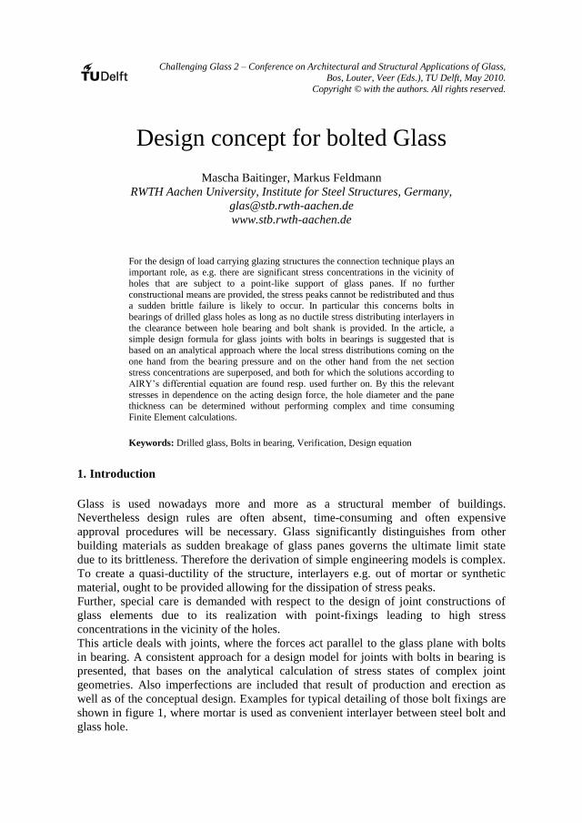
well as of the conceptual design. Examples for typical detailing of those bolt fixings are
shown in figure 1, where mortar is used as convenient interlayer between steel bolt and
glass hole.
Challenging Glass 2
Figure 1a, b and c: Mortar-Interlayer to create ductility behaviour and example of a joint (CCI Munich)
2. Stress equations for bolted joints
To derive stress equations for arbitrary geometries for bolted glass joints the basics of
the statics of plane load-bearing structures are needed. The three static requirements to
fulfil equilibrium, compatibility and material law can be reduced to the differential
equation of AIRY:
0F . (1)
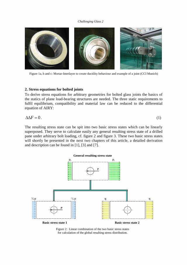
The resulting stress state can be spit into two basic stress states which can be linearly
superposed. They serve to calculate easily any general resulting stress state of a drilled
pane under arbitrary bolt loading, cf. figure 2 and figure 3. These two basic stress states
will shortly be presented in the next two chapters of this article, a detailed derivation
and description can be found in [1], [3] and [7].
Figure 2: Linear combination of the two basic stress states
for calculation of the global resulting stress distribution.
General resulting stress state
Basic stress state 1 Basic stress state 2
Design concept for bolted glass
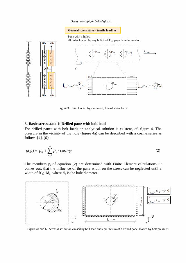
Figure 3: Joint loaded by a moment, free of shear force.
3. Basic stress state 1: Drilled pane with bolt load
For drilled panes with bolt loads an analytical solution is existent, cf. figure 4. The
pressure in the vicinity of the hole (figure 4a) can be described with a cosine series as
follows [4], [6]:
1
0 cos)(n
n nppp (2)
The members pi of equation (2) are determined with Finite Element calculations. It
comes out, that the influence of the pane width on the stress can be neglected until a
width of B ≥ 3do, where do is the hole diameter.
Figure 4a and b: Stress distribution caused by bolt load and equilibrium of a drilled pane, loaded by bolt pressure.
General stress state – tensile loading
Pane with n holes,
all holes loaded by any bolt load Px,i, pane is under tension
Challenging Glass 2
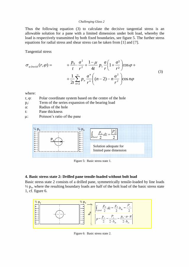
Thus the following equation (3) to calculate the decisive tangential stress is an
allowable solution for a pane with a limited dimension under bolt load, whereby the
load is respectively transmitted by both fixed boundaries, see figure 5. The further stress
equations for radial stress and shear stress can be taken from [1] and [7].
Tangential stress
nr
ann
r
ap
t
r
a
r
ap
tr
a
t
pr
n
n
n
n
basic
cos)2(2
1
cos²
²1
4
1),(
2
2
2
12
20
1,
(3)
where:
r, Polar coordinate system based on the centre of the hole
pi: Term of the series expansion of the bearing load
a: Radius of the hole
t: Pane thickness
: Poisson’s ratio of the pane
Figure 5: Basic stress state 1.
4. Basic stress state 2: Drilled pane tensile-loaded without bolt load
Basic stress state 2 consists of a drilled pane, symmetrically tensile-loaded by line loads
½ px, where the resulting boundary loads are half of the bolt load of the basic stress state
1, cf. figure 6.
Figure 6: Basic stress state 2.
Solution adequate for
limited pane dimension
Design concept for bolted glass
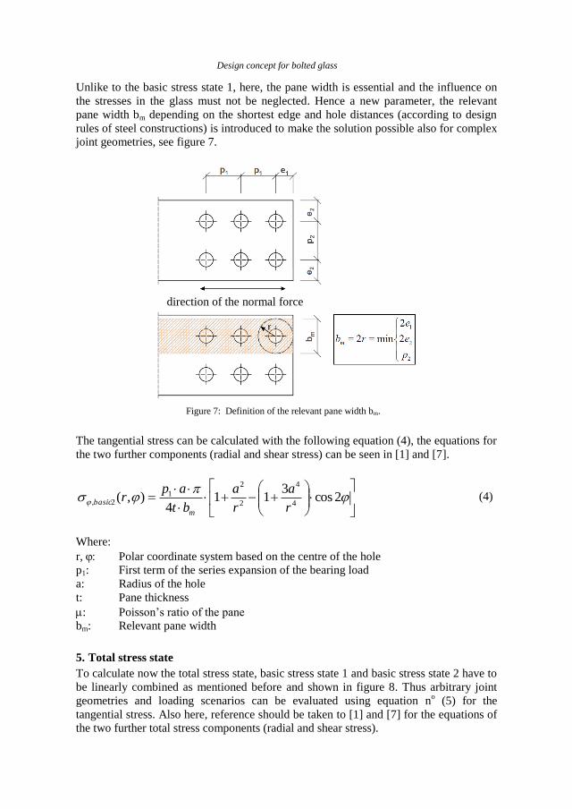
Unlike to the basic stress state 1, here, the pane width is essential and the influence on
the stresses in the glass must not be neglected. Hence a new parameter, the relevant
pane width bm depending on the shortest edge and hole distances (according to design
rules of steel constructions) is introduced to make the solution possible also for complex
joint geometries, see figure 7.
Figure 7: Definition of the relevant pane width bm.
The tangential stress can be calculated with the following equation (4), the equations for
the two further components (radial and shear stress) can be seen in [1] and [7].
2cos
311
4),(
4
4
2
2
12,
r
a
r
a
bt
apr
m
basic (4)
Where:
r, Polar coordinate system based on the centre of the hole
p1: First term of the series expansion of the bearing load
a: Radius of the hole
t: Pane thickness
: Poisson’s ratio of the pane
bm: Relevant pane width
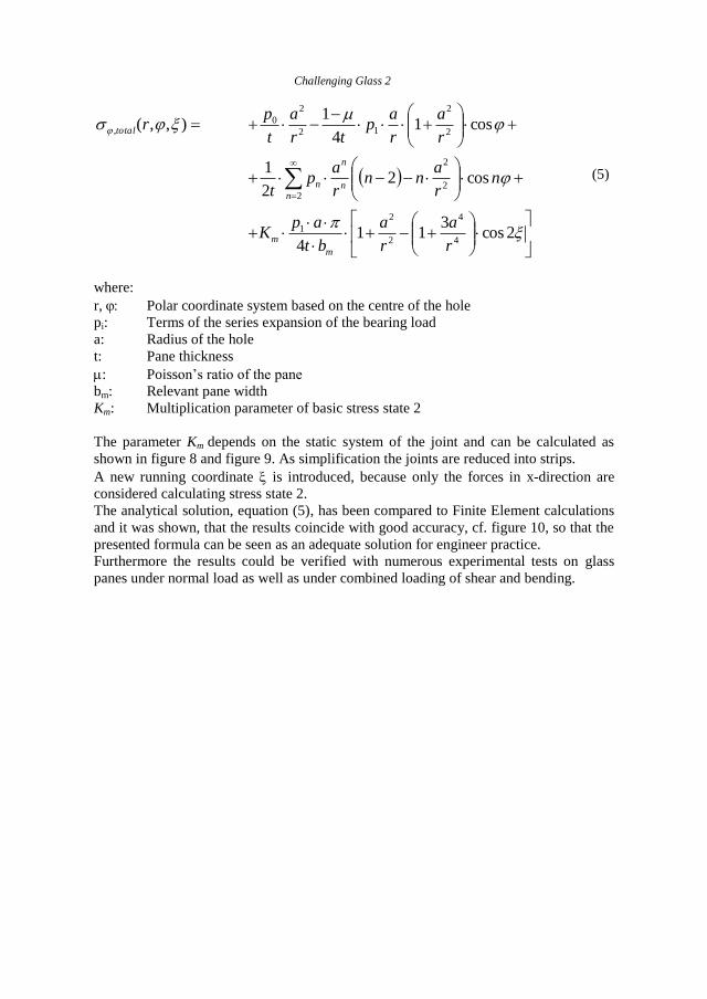
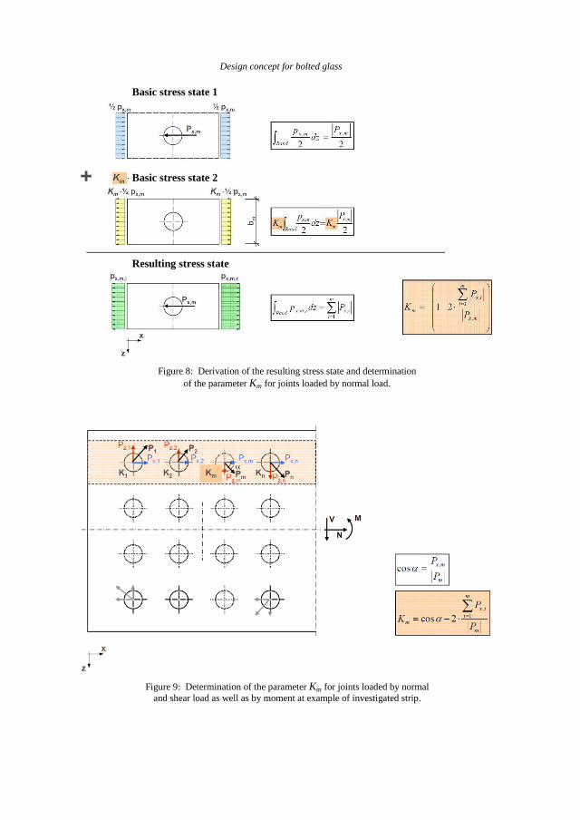
5. Total stress state
To calculate now the total stress state, basic stress state 1 and basic stress state 2 have to
be linearly combined as mentioned before and shown in figure 8. Thus arbitrary joint
geometries and loading scenarios can be evaluated using equation no (5) for the
tangential stress. Also here, reference should be taken to [1] and [7] for the equations of
the two further total stress components (radial and shear stress).
direction of the normal force
Challenging Glass 2
2cos3
114
cos22
1
cos14
1),,(
4
4
2
2
1
2
2
2
2
2
12
2
0,
r
a
r
a
bt
apK
nr
ann
r
ap
t
r
a
r
ap
tr
a
t
pr
m
m
n
n
n
n
total
(5)
where:
r, Polar coordinate system based on the centre of the hole
pi: Terms of the series expansion of the bearing load
a: Radius of the hole
t: Pane thickness
: Poisson’s ratio of the pane
bm: Relevant pane width
Km: Multiplication parameter of basic stress state 2
The parameter Km depends on the static system of the joint and can be calculated as
shown in figure 8 and figure 9. As simplification the joints are reduced into strips.
A new running coordinate is introduced, because only the forces in x-direction are
considered calculating stress state 2.
The analytical solution, equation (5), has been compared to Finite Element calculations
and it was shown, that the results coincide with good accuracy, cf. figure 10, so that the
presented formula can be seen as an adequate solution for engineer practice.
Furthermore the results could be verified with numerous experimental tests on glass
panes under normal load as well as under combined loading of shear and bending.
Design concept for bolted glass
Figure 8: Derivation of the resulting stress state and determination
of the parameter Km for joints loaded by normal load.
Figure 9: Determination of the parameter Km for joints loaded by normal
and shear load as well as by moment at example of investigated strip.
Basic stress state 2
Basic stress state 1
Resulting stress state
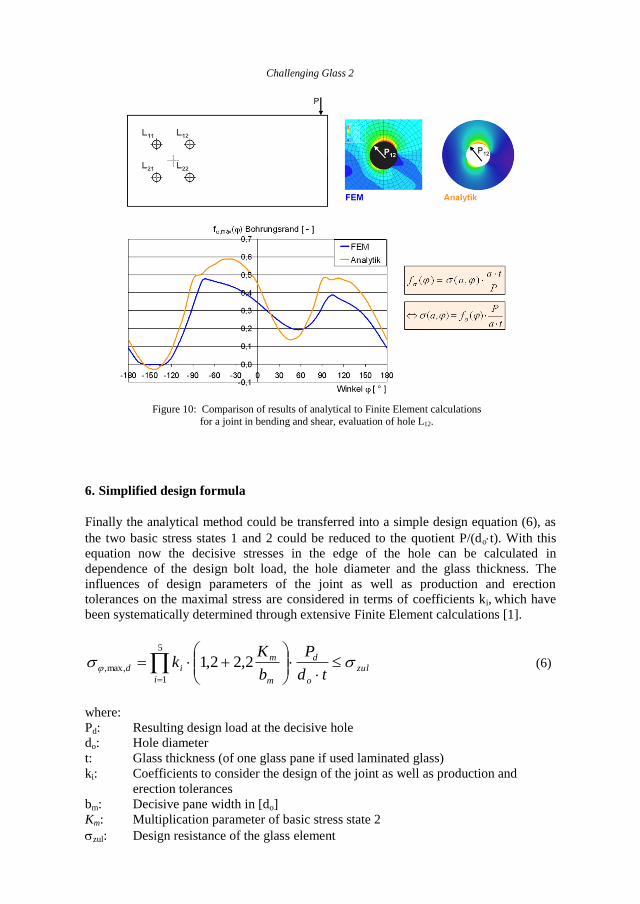
Challenging Glass 2
Figure 10: Comparison of results of analytical to Finite Element calculations
for a joint in bending and shear, evaluation of hole L12.
6. Simplified design formula
Finally the analytical method could be transferred into a simple design equation (6), as
the two basic stress states 1 and 2 could be reduced to the quotient P/(dot). With this
equation now the decisive stresses in the edge of the hole can be calculated in
dependence of the design bolt load, the hole diameter and the glass thickness. The
influences of design parameters of the joint as well as production and erection
tolerances on the maximal stress are considered in terms of coefficients ki, which have
been systematically determined through extensive Finite Element calculations [1].
zul
o
d
m
m
i
idtd
P
b
Kk
2,22,15
1
max,, (6)
where:
Pd: Resulting design load at the decisive hole
do: Hole diameter
t: Glass thickness (of one glass pane if used laminated glass)
ki: Coefficients to consider the design of the joint as well as production and
erection tolerances
bm: Decisive pane width in [do]
Km: Multiplication parameter of basic stress state 2
zul: Design resistance of the glass element
Design concept for bolted glass
Design formula (6) now should be used as follows:
a) Determination of the internal normal and shear forces as well as moment
b) Distribution of the internal forces and moment on the single bolts depending on
the polar moment of inertia and the non-uniform distribution of the normal force
over the joint length
c) Determination of the relevant pane width bm
d) Compilation of the coefficients ki
e) Calculation of the parameter Km
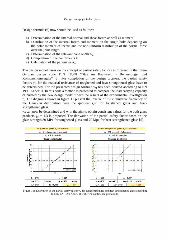
The design model bases on the concept of partial safety factors as foreseen in the future
German design code DIN 18008 “Glas im Bauwesen - Bemessungs- und
Konstruktionsregeln” [8]. For completion of the design proposal the partial safety
factors M for the material resistance of toughened and heat-strengthened glass have to
be determined. For the presented design formula M has been derived according to EN
1990 Annex D. In this code a method is presented to compare the load carrying capacity
calculated by the new design model rt with the results of the experimental investigation
re. The diagrams shown in figure 11 present the inverse of the cumulative frequency of
the Gaussian distribution over the quotient re/rt for toughened glass and heat-
strengthened glass.
M can now be determined and with the aim to obtain consistent values for the both glass
products M = 1,3 is proposed. The derivation of the partial safety factor bases on the
glass strength 80 MPa for toughened glass and 70 Mpa for heat-strengthened glass [5].
Figure 11: Derivation of the partial safety factor M for toughened glass and heat strengthened glass according to DIN EN 1990 Annex D with 75% confidence probability.
Challenging Glass 2
7. Summary
The design of bolts in bearings of drilled glass panes is now significantly simplified due
to the results of recent research projects [1], [7]. Stress states of a drilled glass pane
loaded by bolt loads can now be calculated with a simple design equation without the
use of complex Finite Element calculations.
Further, the design concept could be verified by numerous experimental investigations,
especially for systems loaded by normal force. So far, several tests have been fulfilled
also for more complex systems loaded by bending moment and the solution could be
approved as a method with conservative results.
8. References
[1] Baitinger, M.: Zur Bemessung SL-belasteter Anschlüsse im konstruktiven Glasbau, Dissertation, RWTH
Aachen, Lehrstuhl für Stahlbau , Shaker Verlag 2010
[2] Baitinger, M., Feldmann, M.: Ein Bemessungskonzept für SL-belastete Anschlüsse im konstruktiven Glasbau, Stahlbau 79 (2010) Sonderheft Konstruktiver Glasbau, Ernst & Sohn Verlag, Berlin
[3] Feldmann, M., Pilsl, M., Colomer Segura, C.: Tragfähigkeit von Lochleibungsverbindungen vorgespannter
Glasscheiben zur Ausbildung von Anschlüssen im konstruktiven Glasbau, Stahlbau 77 (2008) Heft 1, S. 17-25, Ernst & Sohn Verlag, Berlin
[4] Girkmann, K.: Flächentragwerke Einführung in die Elastostatik der Scheiben, Platten, Schalen und
Faltwerke, Springer-Verlag Wien - New York, Unveränderter Nachdruck 1974 [5] Laufs, W.: Ein Bemessungskonzept zur Festigkeit thermisch vorgespannter Gläser; Dissertation am
Lehrstuhl für Stahlbau RWTH Aachen; Shaker Verlag 2000
[6] Techen, H.: Fügetechnik für den konstruktiven Glasbau, Dissertation, Bericht Nr. 11 Technische Universität Darmstadt Institut für Statik, 1997
[7] Schlussbericht Nr. 14197/N „Stahl-Glas-Verbindungen in Hinblick auf die Normung“, DASt-
Forschungsbericht Nr. 2/07 [8] E DIN 18008: Glas im Bauwesen - Bemessungs- und Konstruktionsregeln, Beuth Verlag, Berlin