design and simulation of microstrip directional coupler ... · design and simulation of microstrip...
TRANSCRIPT
DESIGN AND SIMULATION OF MICROSTRIP DIRECTIONAL COUPLER WITH TIGHT STRUCTURE AND HIGH DIRECTIVITY*
Tongning Hu #, Dong Li, Lei Cao, Bin Qin, Jun Yang, Tiaoqin Yu, Jiang Huang Huazhong University of Science and Technology, Wuhan, Hubei 430074, China
AbstractThe design of Cyclotron CYCHU-10 has been carried
out at Huazhong University of Science and Technology (HUST). Because of the low centre frequency (99MHz) of its RF system, we should choose suitable directional couplers for the RF system which is supposed to be high-directivity and tight-structure. This paper analyzes and synthesizes kinds of directional couplers, especially microstrip structure and lumped element coupler, for their tinier volume at the low centre frequency compared with other structures. The achievement of the high-directivity with proposed configuration is carried out by adding an inductor to decrease the even and odd mode phase difference. Tight-structure is performed by the Lumped elements, which is easy to fabricate due to the multilayer microstrip line techniques used in MICs and MMICs.
INTRODUCTIONAfter the first directional coupler was reported, various
types of directional couplers consisting of one quarter wavelength transmission lines (TLs) have been used in many RF systems [1]. And many researches on the theory, design, fabrication and simulation for the TEM-lines such as coupled-line directional couplers were made and numerous relevant papers were published [2].
Due to the higher level of integration of RF circuits on a single substrate, microstrip directional couplers have gotten much attention and been widely used for realizing such directional couplers in the design of RF systems [3]. However, because of the inhomogeneity of microstrip lines, the even and odd mode propagation velocities for coupled microstrip lines are not equal resulting in poor directivity, which becomes worse as the coupling is decreased[4], it is necessary to apply phase velocity compensation techniques to improve coupler directivity. Several previously techniques have been used to resolve the problem of poor directivity in parallel coupled microstrip lines.
Generally speaking, the design theory for TEM TL couplers is based on an assumption of the same phase velocities of the even and odd propagation mode. This is not suitable for coupled microstrip lines, since they have unequal even- and odd-mode phase velocities. Previously compensation techniques can be classified into distributed and lumped compensation approaches.
The former is to modify the parallel coupled-line structure such that the phase velocities of both modes are equalized. Such as typical wiggly-line coupler which increases the physical lengths of the adjacent edges of the
microstrip lines. The latter involves adding external reactive components which are capacitive and inductive compensation techniques. Compensated microstrip directional coupler and the edge capacitors or inductors added affect the odd mode by equivalent extension of the TL electrical lengths, with almost no effect on even mode [5].
Furthermore, lumped elements (LEs) are very attractive in the sense of smaller size and lower cost compared with TL circuits, due to their smaller element dimensions and the multilevel fabrication process. With these characteristics, the LE design methods have been already applied to TL circuits such as a branchline coupler or a rat-race [6].
LUMPED ELEMENT DIRECTIONAL COUPLERS
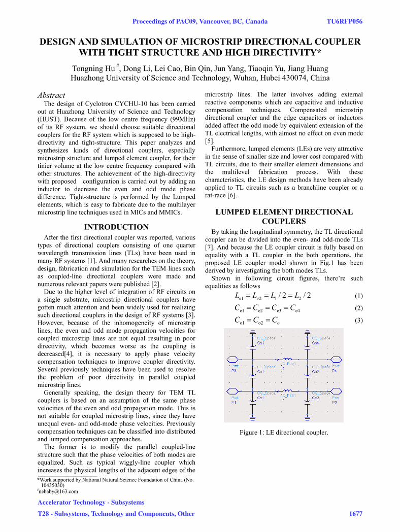
By taking the longitudinal symmetry, the TL directional coupler can be divided into the even- and odd-mode TLs [7]. And because the LE coupler circuit is fully based on equality with a TL coupler in the both operations, the proposed LE coupler model shown in Fig.1 has been derived by investigating the both modes TLs.
Shown in following circuit figures, there’re such equalities as follows
2/2/ 212e1 LLLL e (1)
e4e3e2e1 CCCC (2)
oCCC o2o1 (3)
Figure 1: LE directional coupler.
___________________________________________
*Work supported by National Natural Science Foundation of China (No. 10435030)
Proceedings of PAC09, Vancouver, BC, Canada TU6RFP056
Accelerator Technology - Subsystems
T28 - Subsystems, Technology and Components, Other 1677
(a)
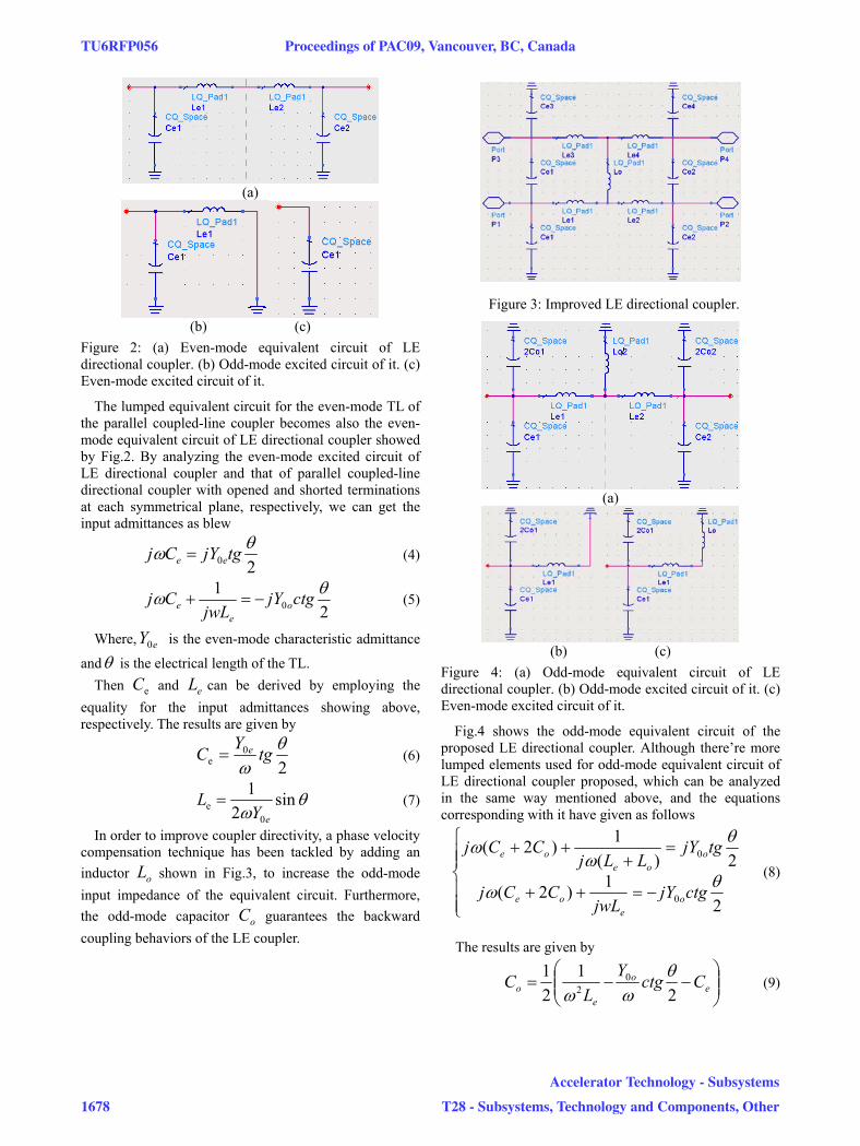
(b) (c) Figure 2: (a) Even-mode equivalent circuit of LE directional coupler. (b) Odd-mode excited circuit of it. (c) Even-mode excited circuit of it.
The lumped equivalent circuit for the even-mode TL of the parallel coupled-line coupler becomes also the even-mode equivalent circuit of LE directional coupler showed by Fig.2. By analyzing the even-mode excited circuit of LE directional coupler and that of parallel coupled-line directional coupler with opened and shorted terminations at each symmetrical plane, respectively, we can get the input admittances as blew
20 tgjYCj ee (4)
21
0 ctgjYjwL
Cj oe
e (5)
Where, is the even-mode characteristic admittance
andeY0
is the electrical length of the TL. Then and can be derived by employing the
equality for the input admittances showing above, respectively. The results are given by
eC eL
20
e tgY
C e (6)
sin2
1
0e
eYL (7)
In order to improve coupler directivity, a phase velocity compensation technique has been tackled by adding an inductor shown in Fig.3, to increase the odd-mode input impedance of the equivalent circuit. Furthermore, the odd-mode capacitor guarantees the backward coupling behaviors of the LE coupler.
oL
oC
Figure 3: Improved LE directional coupler.
(a)
(b) (c) Figure 4: (a) Odd-mode equivalent circuit of LE directional coupler. (b) Odd-mode excited circuit of it. (c) Even-mode excited circuit of it.
Fig.4 shows the odd-mode equivalent circuit of the proposed LE directional coupler. Although there’re more lumped elements used for odd-mode equivalent circuit of LE directional coupler proposed, which can be analyzed in the same way mentioned above, and the equations corresponding with it have given as follows
21)2(
2)(1)2(
0
0
ctgjYjwL
CCj
tgjYLLj
CCj
oe
oe
ooe
oe
(8)
The results are given by
eo
eo Cctg
YL
C2
121 0
2 (9)
TU6RFP056 Proceedings of PAC09, Vancouver, BC, Canada
1678
Accelerator Technology - Subsystems
T28 - Subsystems, Technology and Components, Other
e
ooe
o LtgYCC
L
2)2(
1
02
(10)
DESIGN AND SIMULATIONS
In order to design a suitable directional coupler for RF system of CYCHU-10, with the centre frequency being 99MHz. By using the configuration, design theory, and the design formulas we have derived above, the LE backward directional coupler has been designed and simulated here. For accurate fabrication, the centre frequencies for both cases have been set identically to be 99MHz. Design targets due to the requirements of the presented RF system is showed in Table 1.
Table 1: Desired Targets of the Design
Targets Values
C -25dB
I -40dB
D -15dB
The parameter values calculated by the linecalc module of ADS and Matlab under the condition of characteristic impedance and centre frequency f50Z0 c=99MHz. Simulation results of the proposed LE directional coupler in the ADS circumstance have been shown by Table 2, Fig.5 and Table 3, respectively.
Table 2: Element Values of LE Directional Coupler
Elements Values
Ce 34.005pF
Le 38.010nH
Co 1.813pF
Lo 318.960nH
Table 3: Simulation results in the bandwidth
Targets 98.5MHz 99MHz 99.5MHz
C -25.399dB -25.409dB -25.417dB
I -46.473dB -46.688dB -46.357dB
D -21.074dB -21.279dB -20.940dB
Loss -34.252dB -34.381dB -33.963dB
Matching -0.398dB -0.400dB -0.402dB
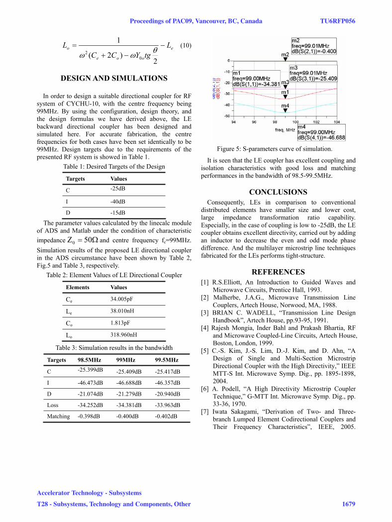
Figure 5: S-parameters curve of simulation.
It is seen that the LE coupler has excellent coupling and isolation characteristics with good loss and matching performances in the bandwidth of 98.5-99.5MHz.
CONCLUSIONS Consequently, LEs in comparison to conventional
distributed elements have smaller size and lower cost, large impedance transformation ratio capability. Especially, in the case of coupling is low to -25dB, the LE coupler obtains excellent directivity, carried out by adding an inductor to decrease the even and odd mode phase difference. And the multilayer microstrip line techniques fabricated for the LEs performs tight-structure.
REFERENCES [1] R.S.Elliott, An Introduction to Guided Waves and
Microwave Circuits, Prentice Hall, 1993. [2] Malherbe, J.A.G., Microwave Transmission Line
Couplers, Artech House, Norwood, MA, 1988. [3] BRIAN C. WADELL, “Transmission Line Design
Handbook”, Artech House, pp.93-95, 1991. [4] Rajesh Mongia, Inder Bahl and Prakash Bhartia, RF
and Microwave Coupled-Line Circuits, Artech House, Boston, London, 1999.
[5] C.-S. Kim, J.-S. Lim, D.-J. Kim, and D. Ahn, “A Design of Single and Multi-Section Microstrip Directional Coupler with the High Directivity,” IEEE MTT-S Int. Microwave Symp. Dig., pp. 1895-1898, 2004.
[6] A. Podell, “A High Directivity Microstrip Coupler Technique,” G-MTT Int. Microwave Symp. Dig., pp. 33-36, 1970.
[7] Iwata Sakagami, “Derivation of Two- and Three-branch Lumped Element Codirectional Couplers and Their Frequency Characteristics”, IEEE, 2005.
Proceedings of PAC09, Vancouver, BC, Canada TU6RFP056
Accelerator Technology - Subsystems
T28 - Subsystems, Technology and Components, Other 1679