design and fabrication of 12 ghz microstrip …jestec.taylors.edu.my/vol 11 issue 3 march...
TRANSCRIPT
Journal of Engineering Science and Technology Vol. 11, No. 3 (2016) 431 - 442 © School of Engineering, Taylor’s University
431
DESIGN AND FABRICATION OF 12 GHZ MICROSTRIP DIRECTIONAL COUPLER FOR RF/MICROWAVE APPLICATION
AZAHAR FAUZI1, ZAIRI ISMAEL RIZMAN
2,*
1Electrical Engineering Department, Politeknik Kuala Terengganu, Malaysia 2Faculty of Electrical Engineering, Universiti Teknologi MARA (Terengganu, Malaysia
*Corresponding Author: [email protected]
Abstract
Microstrip coupled line is parallel coupled transmission lines formed by coupling two conducting strips (resonator) with the same width together at a
certain distance. This paper presents the design of microstrip directional coupler
without the prior knowledge of the physical geometry. A general configuration
directional coupler will be determined by creating a layout in the Agilent
Advanced Design System (ADS) and momentum. In order to perform simulation, a substrate as well as metallization and mesh should be defined.
Hence, the required s-parameter response of the coupler could be obtained. The
design will then fabricate on top of RT Duroid 6010 substrate, and finally
undergo measuring through Vector Network Analyzer (VNA) to evaluate their
S-parameter characteristics. Simulated results show insertion loss, isolation,
coupling (10.82 dB), and return loss were within the acceptable limits. Directivity of better than 23 dB was achieved in the simulated response. The
coupling (9.99 dB) of fabricated circuit shows a good agreement with the
required specification (10 dB), but the directivity 10.61 dB is quite low in
practice. The reason for the discrepancy could, however, due to discontinuities,
measuring errors, and fabrication error. However, coupling values show a good
agreement between the simulation and measured results.
Keywords: Microstrip, Coupled line, Directional coupler, Coupling, Directivity.
1. Introduction
The microstrip is a mixed dielectric system or inhomogeneous, having solid
dielectric below, and air above as demonstrated in Fig. 1. These mixed systems
can only support multi-modal propagation behaviour at any particular frequency,
432 A. Fauzi and Z. I. Rizman
Journal of Engineering Science and Technology March 2016, Vol. 11(3)
Nomenclatures
C Coupling, dB
dB Decibel
E Electric field, V/m
F Centre frequency, GHz
GHz Giga hertz
H Substrate thickness, mm
l/L Length, mm
S Scattering parameter
s Spacing, mm
S11 Return loss, dB
S21 Coupled signal, dB
S31 Isolation , dB
S41 Transmitted signal (transmission)
W Width, mm
Zo Output impedance, Ω
Zoe Even-mode output impedance, Ω
Zoo Odd-mode output impedance, Ω
Greek Symbols
βe Even-mode phase constant
βo Odd-mode phase constant
εr Substrate permittivity, As/Vm
Γe Even-mode reflection coefficient
Γo Odd-mode reflection coefficient
Abbreviations
ADS Advanced Design System
MCLIN Microstrip Coupled Line
MLIN Microstrip Line
PCB Printed Circuit Board
SMA SubMiniature version A
TEM Transverse Electro-magnetic
VNA Vector Network Analyzer
VSWR Voltage Standing Wave Ratio
due to the discontinuity in the electric structure. In other words, the structure does
not support pure TEM wave.
The field patterns in a microstrip are such that the bulk of the energy is
transmitted in a TEM like mode, and this approximation is often made, so
propagation in microstrip is often referred as ‘quasi-TEM’ [1]. TEM stands for
Transverse Electro-magnetic, and means that the electric and magnetic fields are
entirely directed in a plane transverse to the direction of propagation.
Parallel coupled line couplers are widely used for many wireless and
microwave applications because they can be easily implemented and incorporated
with other circuits. Microstrip coupled line is parallel coupled transmission lines
formed by coupling two conducting strips (resonator) with the same width
together at a certain distance, as depicted in Fig. 2 [2]. The odd- and even-mode

Design and Fabrication of 12 GHZ Microstrip Directional Coupler for . . . . 433
Journal of Engineering Science and Technology March 2016, Vol. 11(3)
characteristic impedance can be analyzed by individual even-mode and odd-mode
circuits. It should be noticed that, phase velocity of even-mode is greater than
odd-mode phase velocity due to more of the odd-mode electric fields (E) travels
in the air. Then, the wavelength of individual mode is absolutely different from
each other [3].
Fig. 1. Microstrip line.
Fig. 2. Top view of two port parallel coupled line.
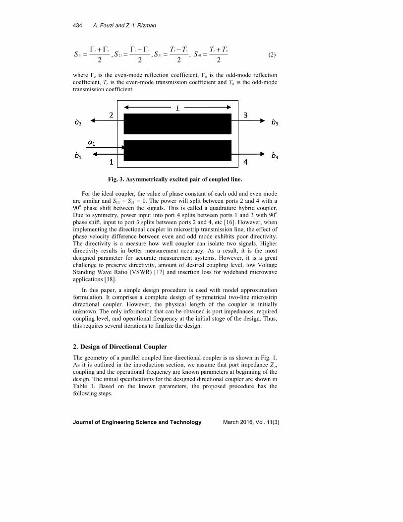
The analysis of a coupled transmission line can be described by S-parameter in
order to observe the coupling characteristics. As shown in Fig. 3, all ports are
labelled, and are all terminated in the system characteristic impedance Zo. In this
case, it is assumed that the two lines have the same characteristic impedance, and
so the whole structure is symmetrical. If port 1 is the input port, then the
characteristics can be determined by derivation based on the four ports, as shown
in Eq. (1).
, , , (1)
where S11 is the return loss, S21 is the coupled signal, S31 is the isolation and S41 is
the transmitted signal (transmission). Each of even-mode and odd-mode has
associated characteristic impedance and phase constant, Zoe and βe for the even
mode and Zoo and βo for the odd mode. The derivations for the above four
parameters are complex and mentioned in many published sources [4-15]. The
final definitions are expressed as Eq. (2).
1
1
11
a
bS =
1
2
21
a
bS =
1
3
31
a
bS =
1
4
41
a
bS =
Ground Plane Dielectric
Conductor
h
w
434 A. Fauzi and Z. I. Rizman
Journal of Engineering Science and Technology March 2016, Vol. 11(3)
, , , (2)
where Γe is the even-mode reflection coefficient, Γo is the odd-mode reflection
coefficient, Te is the even-mode transmission coefficient and To is the odd-mode
transmission coefficient.
Fig. 3. Asymmetrically excited pair of coupled line.
For the ideal coupler, the value of phase constant of each odd and even mode
are similar and S11 = S31 = 0. The power will split between ports 2 and 4 with a
90o phase shift between the signals. This is called a quadrature hybrid coupler.
Due to symmetry, power input into port 4 splits between ports 1 and 3 with 90o
phase shift, input to port 3 splits between ports 2 and 4, etc [16]. However, when
implementing the directional coupler in microstrip transmission line, the effect of
phase velocity difference between even and odd mode exhibits poor directivity.
The directivity is a measure how well coupler can isolate two signals. Higher
directivity results in better measurement accuracy. As a result, it is the most
designed parameter for accurate measurement systems. However, it is a great
challenge to preserve directivity, amount of desired coupling level, low Voltage
Standing Wave Ratio (VSWR) [17] and insertion loss for wideband microwave
applications [18].
In this paper, a simple design procedure is used with model approximation
formulation. It comprises a complete design of symmetrical two-line microstrip
directional coupler. However, the physical length of the coupler is initially
unknown. The only information that can be obtained is port impedances, required
coupling level, and operational frequency at the initial stage of the design. Thus,
this requires several iterations to finalize the design.
2. Design of Directional Coupler
The geometry of a parallel coupled line directional coupler is as shown in Fig. 1.
As it is outlined in the introduction section, we assume that port impedance Zo,
coupling and the operational frequency are known parameters at beginning of the
design. The initial specifications for the designed directional coupler are shown in
Table 1. Based on the known parameters, the proposed procedure has the
following steps.
211
oe
SΓ+Γ
=2
21
oe
SΓ−Γ
=2
31
oe TTS
−=
241
oe TTS
+=
Design and Fabrication of 12 GHZ Microstrip Directional Coupler for . . . . 435
Journal of Engineering Science and Technology March 2016, Vol. 11(3)
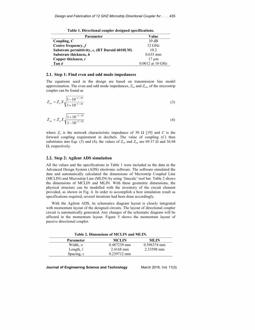
Table 1. Directional coupler designed specifications.
Parameter Value
Coupling, C 10 dB
Centre frequency, f 12 GHz
Substrate permittivity, εr (RT Duroid 6010LM) 10.2
Substrate thickness, h 0.635 mm
Copper thickness, t 17 µm
Tan δ 0.0012 at 10 GHz
2.1. Step 1: Find even and odd mode impedances
The equations used in the design are based on transmission line model
approximation. The even and odd mode impedances, Zoe and Zoo, of the microstrip
coupler can be found as
20/
20/
101
101C
C
ooo XZZ−
−
+
−=
(3)
20/
20/
101
101C
C
ooe XZZ−
−
−
+=
(4)
where Zo is the network characteristic impedance of 50 Ω [19] and C is the
forward coupling requirement in decibels. The value of coupling (C) then
substitutes into Eqs. (3) and (4), the values of Zoe and Zoo are 69.37 Ω and 36.04
Ω, respectively.
2.2. Step 2: Agilent ADS simulation
All the values and the specifications in Table 1 were included as the data in the
Advanced Design System (ADS) electronic software. The software simulated the
data and automatically calculated the dimensions of Microstrip Coupled Line
(MCLIN) and Microstrip Line (MLIN) by using ‘linecalc’ tool bar. Table 2 shows
the dimensions of MCLIN and MLIN. With these geometric dimensions, the
physical structure can be modelled with the inventory of the circuit element
provided, as shown in Fig. 4. In order to accomplish a best simulation result as
specifications required, several iterations had been done accordingly.
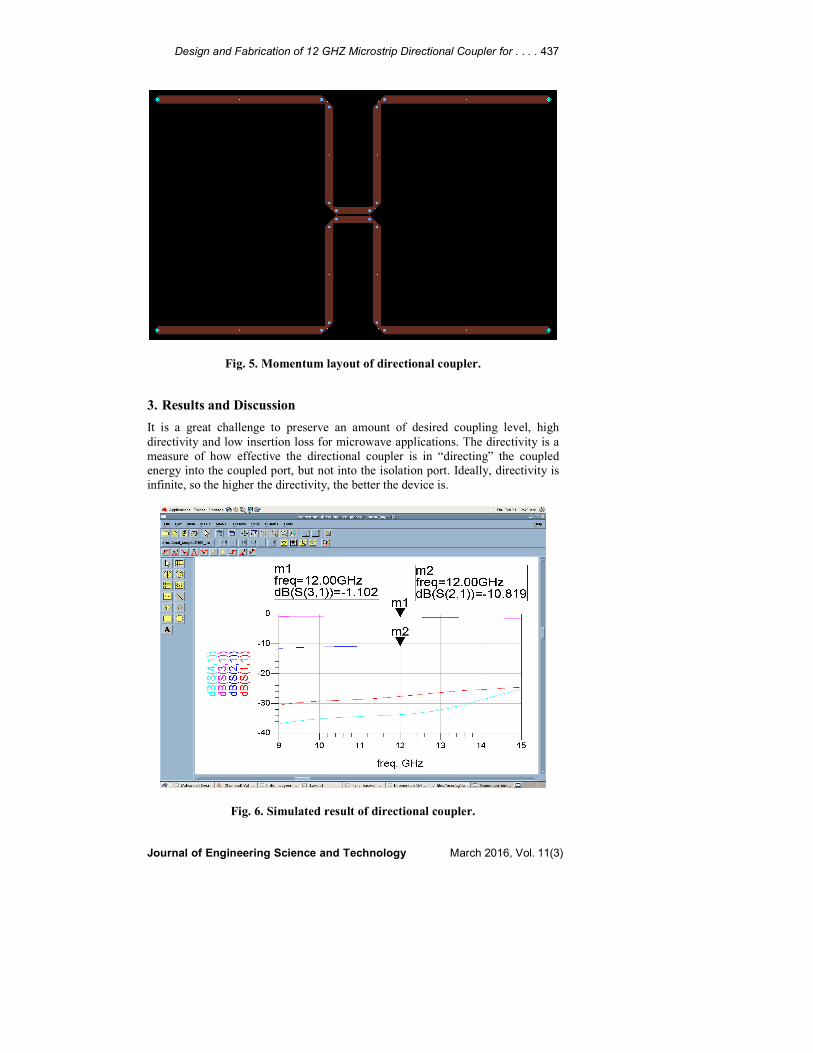
With the Agilent ADS, its schematics diagram layout is closely integrated
with momentum layout of the designed circuits. The layout of directional coupler
circuit is automatically generated. Any changes of the schematic diagram will be
affected in the momentum layout. Figure 5 shows the momentum layout of
passive directional coupler.
Table 2. Dimensions of MCLIN and MLIN.
Parameter MCLIN MLIN
Width, w 0.487239 mm 0.596374 mm
Length, l 2.4168 mm 2.33598 mm
Spacing, s 0.239712 mm
436 A. Fauzi and Z. I. Rizman
Journal of Engineering Science and Technology March 2016, Vol. 11(3)
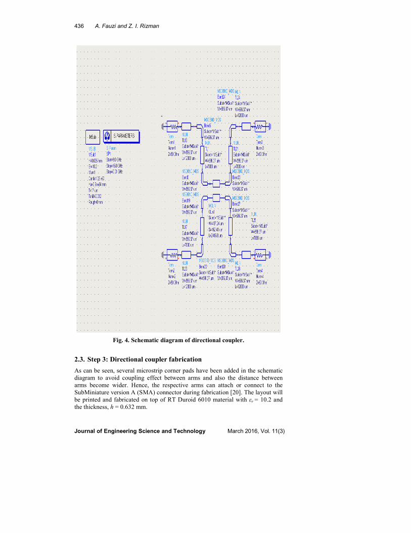
Fig. 4. Schematic diagram of directional coupler.
2.3. Step 3: Directional coupler fabrication
As can be seen, several microstrip corner pads have been added in the schematic
diagram to avoid coupling effect between arms and also the distance between
arms become wider. Hence, the respective arms can attach or connect to the
SubMiniature version A (SMA) connector during fabrication [20]. The layout will
be printed and fabricated on top of RT Duroid 6010 material with εr = 10.2 and
the thickness, h = 0.632 mm.
Design and Fabrication of 12 GHZ Microstrip Directional Coupler for . . . . 437
Journal of Engineering Science and Technology March 2016, Vol. 11(3)
Fig. 5. Momentum layout of directional coupler.
3. Results and Discussion
It is a great challenge to preserve an amount of desired coupling level, high
directivity and low insertion loss for microwave applications. The directivity is a
measure of how effective the directional coupler is in “directing” the coupled
energy into the coupled port, but not into the isolation port. Ideally, directivity is
infinite, so the higher the directivity, the better the device is.
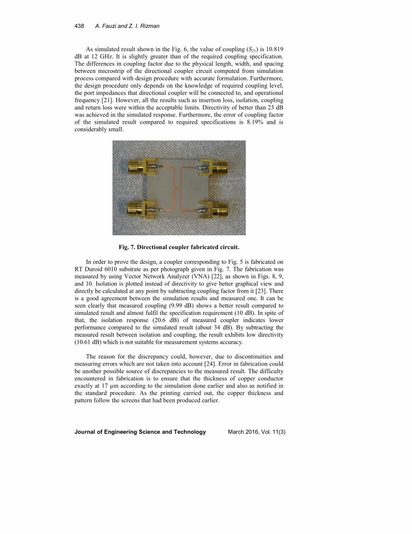
Fig. 6. Simulated result of directional coupler.
438 A. Fauzi and Z. I. Rizman
Journal of Engineering Science and Technology March 2016, Vol. 11(3)
As simulated result shown in the Fig. 6, the value of coupling (S21) is 10.819
dB at 12 GHz. It is slightly greater than of the required coupling specification.
The differences in coupling factor due to the physical length, width, and spacing
between microstrip of the directional coupler circuit computed from simulation
process compared with design procedure with accurate formulation. Furthermore,
the design procedure only depends on the knowledge of required coupling level,
the port impedances that directional coupler will be connected to, and operational
frequency [21]. However, all the results such as insertion loss, isolation, coupling
and return loss were within the acceptable limits. Directivity of better than 23 dB
was achieved in the simulated response. Furthermore, the error of coupling factor
of the simulated result compared to required specifications is 8.19% and is
considerably small.
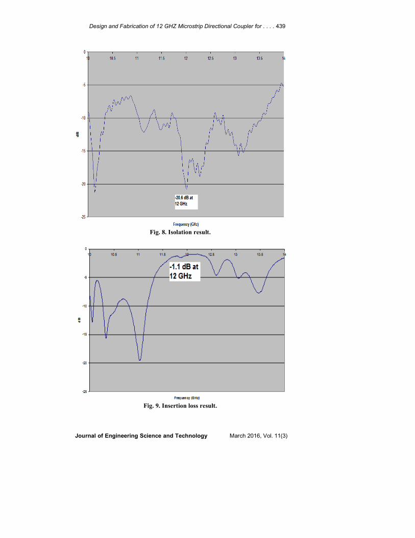
Fig. 7. Directional coupler fabricated circuit.
In order to prove the design, a coupler corresponding to Fig. 5 is fabricated on
RT Duroid 6010 substrate as per photograph given in Fig. 7. The fabrication was
measured by using Vector Network Analyzer (VNA) [22], as shown in Figs. 8, 9,
and 10. Isolation is plotted instead of directivity to give better graphical view and
directly be calculated at any point by subtracting coupling factor from it [23]. There
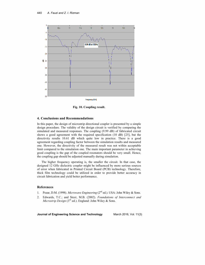
is a good agreement between the simulation results and measured one. It can be
seen clearly that measured coupling (9.99 dB) shows a better result compared to
simulated result and almost fulfil the specification requirement (10 dB). In spite of
that, the isolation response (20.6 dB) of measured coupler indicates lower
performance compared to the simulated result (about 34 dB). By subtracting the
measured result between isolation and coupling, the result exhibits low directivity
(10.61 dB) which is not suitable for measurement systems accuracy.
The reason for the discrepancy could, however, due to discontinuities and
measuring errors which are not taken into account [24]. Error in fabrication could
be another possible source of discrepancies to the measured result. The difficulty
encountered in fabrication is to ensure that the thickness of copper conductor
exactly at 17 µm according to the simulation done earlier and also as notified in
the standard procedure. As the printing carried out, the copper thickness and
pattern follow the screens that had been produced earlier.
Design and Fabrication of 12 GHZ Microstrip Directional Coupler for . . . . 439
Journal of Engineering Science and Technology March 2016, Vol. 11(3)
Fig. 8. Isolation result.
Fig. 9. Insertion loss result.
440 A. Fauzi and Z. I. Rizman
Journal of Engineering Science and Technology March 2016, Vol. 11(3)
Fig. 10. Coupling result.
4. Conclusions and Recommendations
In this paper, the design of microstrip directional coupler is presented by a simple
design procedure. The validity of the design circuit is verified by comparing the
simulated and measured responses. The coupling (9.99 dB) of fabricated circuit
shows a good agreement with the required specification (10 dB) [25], but the
directivity results 10.61 dB which quite low in practice. There is a good
agreement regarding coupling factor between the simulation results and measured
one. However, the directivity of the measured result was not within acceptable
limit compared to the simulation one. The main important parameter in achieving
good coupling is the gap of the coupled resonators should be very small. Hence,
the coupling gap should be adjusted manually during simulation.
The higher frequency operating is, the smaller the circuit. In that case, the
designed 12 GHz dielectric coupler might be influenced by more serious sources
of error when fabricated in Printed Circuit Board (PCB) technology. Therefore,
thick film technology could be utilized in order to provide better accuracy in
circuit fabrication and yield better performance.
References
1. Pozar, D.M. (1998). Microwave Engineering (2nd
ed.). USA: John Wiley & Sons.
2. Edwards, T.C.; and Steer, M.B. (2002). Foundations of Interconnect and
Microstrip Design (3rd
ed.). England: John Wiley & Sons.

Design and Fabrication of 12 GHZ Microstrip Directional Coupler for . . . . 441
Journal of Engineering Science and Technology March 2016, Vol. 11(3)
3. Pennock, S.R.; and Shepherd, P.R. (1998). Microwave Engineering with
Wireless Applications (1st ed.). McGraw-Hill Professional.
4. Eroglu, A.; Goulding, R.; Ryan, P.; Caughman, J.; and Rasmussen, D.
(2010). Novel broadband multilayer microstrip directional coupler.
Proceedings of the Antennas and Propagation Society International
Symposium. Toronto, Canada, 1-4.
5. Fauzi, A. (2008). Multilayer Filter Design. MSc Dissertation. UK: University
of Surrey.
6. Farafonov, O.; Zarubina, S; and Voropay, O. (2004). Probing of tolerances
on elements microstrip directed couplers. Proceedings of the International
Conference Modern Problems of Radio Engineering, Telecommunication and
Computer Science. Lviv-Slavsko, Ukraine, 156-158.
7. Lee, T.H. (2004). Planar Microwave Engineering: A Practical Guide to
Theory, Measurements and Circuits (1st ed.). New York: Cambridge
University Press.
8. Hock, G.H.; and Chakrabarty, C.K. (2005). Design of a 5.8 GHz directional
coupler using electronics design automation tool. Proceedings of the Asia-
Pacific Conference on Applied electromagnetics. 194-197.
9. Hussein, A. (2005). Advanced RF Engineering for Wireless Systems and
Networks. New Jersey: John Wiley & Sons.
10. Li, E.S.; and Chou, C.P. (2011). Designs of broadband cavity-coupled
microstrip directional couplers. Proceedings of the International Symposium
Antennas and Propagation. 16-18.
11. Tas, V.; and Alatar, A. (2013). Using phase relations in microstrip directional
couplers to achieve high directivity. IEEE Transactions on Microwave
Theory and Techniques, 61(12), 4063-4071.
12. Tang, C.W.; and Chen, M.G. (2012). Compensated microstrip coupled line
and its application on impedance transformer. Electronic Letters, 48(14),
853-854.
13. Wu, Y.; Sun, W.; Leung, S.W.; Diao, Y.; Chan, K.H.; and Siu, Y.M. (2013).
Single-layer high-directivity coupled-line coupler with tight coupling. IEEE
Transactions on Microwave Theory and Techniques, 61(2), 746-753.
14. Gupta, S.D.; and Srivastava, M.C. (2012). Multilayer microstrip antenna
quality factor optimization for bandwidth enhancement. Journal of
Engineering Science and Technology (JESTEC), 7(6), 756-773.
15. Carr, J.J. (2002). RF Components and Circuits (1st ed.). Oxford: Newnes.
16. Mass, S.A. (1998). The RF and Microwave Circuit Design Cookbook (2nd
ed.). Boston: Artech House.
17. Aris, M.A.; Kadir, E.A.; Zain, M.Y.M.; Rizman, Z.I.; and Husin, N.H.R.
(2013). A miniature UHF rectangular microstrip RFID tag antenna for
aluminium can application. World Applied Sciences Journal, 23(23), 96-102.
18. Eroglu, A.; and Lee, J.K. (2008). The complete design of microstrip
directional couplers using the systhesis technique. IEEE Transactions on
Instrumentation and Measurement, 57(12), 2756-2761.
442 A. Fauzi and Z. I. Rizman
Journal of Engineering Science and Technology March 2016, Vol. 11(3)
19. Jaafar, A.N.; Rizman, Z.I.; and Husin, N.H.R. (2013). Bandwidth
enhancement of CPW double patch antenna for WLAN application. Journal
of Basic and Applied Scientific Research, 3(11), 324-331.
20. Dzulkefli, N.N.S.N.; Rizman, Z.I.; and Husin, N.H.R. (2013). Double layer
microstrip antenna with 3 by 3 array of square parasitic patches using coaxial
feeding technique for WiMAX application. Journal of Basic and Applied
Scientific Research, 3(11), 399-404.
21. Shafie, R; Rizman, Z.I.; and Husin, N.H.R. (2013). Enhancement of
microstrip circular patch antenna performances using DGS technique for
wireless communication application. Journal of Basic and Applied Scientific
Research, 3(11), 365-372.
22. Jayanthy, T.; and Maheswari, S. (2008). Design and simulation of microstrip
directional coupler. Proceedings of the International Conference on
Microwave, 782-783.
23. Gupta, V.K.; Kumar, P.P.; and Rao, C.V.N. (2013). A novel miniaturized,
wideband, high directivity microstrip coupler on FR4. Proceedings of the
International Conference Microwave and Photonic. Johor, Malaysia, 1-4.
24. Masot, F.; Medina, F.; and Horno, M. (1994). Analysis and experimental
validation of a type of three-microstrip directional coupler. IEEE
Transactions on Microwave Theory and Techniques, 42(9), 1624-1631.
25. Omar, Suziana; Rizman, Z.I.; and Husin, N.H.R. (2013). Gain enhancement
of rectangular microstrip patch antenna using t-probe fed for mobile and
radio wireless communication applications. Journal of Basic and Applied
Scientific Research, 3(10), 456-464.