design and performance of pwr and bwr fuel. - indico...
TRANSCRIPT

1
Design and Performance of PWR and BWR Fuel Workshop on Modeling and Quality Control for Advanced and Innovative Fuel Technologies
Lecture given by Hans G. Weidinger
At International Centre of Theoretical Physics In Trieste on November 21, 2005
Abstract .......................................................................................................................................... 1 Introductory Remarks .................................................................................................................. 1 Retrospective Historical Review ................................................................................................ 1 High Burn-Up LWR Fuel, General Situation and Near Future Perspectives ...................... 2 PWR and BWR Fuel Designs..................................................................................................... 4
PWR Fuel Assembly and Component Design,.................................................................... 4 PWR fuel materials .................................................................................................................. 5 BWR Fuel Assembly and Component Design,.................................................................... 6 BWR fuel materials .................................................................................................................. 8
LWR Fuel Operational Performance ......................................................................................... 8 PWR Performance ................................................................................................................... 8 BWR Performance ................................................................................................................... 9
Abstract
A short overview is given on the historical development of the design and the performance of LWR fuel. The today existing designs provide a high level of economic utilization and reliable performance of this fuel. On the other hand there is still a need for better understanding of various mechanism leading to fuel defects at the existing high level of economy, i.e. mainly high burn-up. And there is a potential for further development towards even more reliability and economy.
Introductory Remarks
The target of this lecture is to provide overview on typical design targets and features of of PWR and BWR fuel and the fuel performance achievable by those designs. It is, of course not possible to go into any detail of the today used designs. However, it will try to describe the today used technology of PWR and BWR fuel to achieve best possible reliability, efficiency and safety.
Retrospective Historical Review
PWR and BWR fuel technology now exists since more than 40 years. To achieve the present high level of reliability and economy a remarkable way with substantial efforts had to be gone covering R&D, design, fabrication and performance evaluation. This way led from energy yield of very initially about 20,000 MWd/tU or less to currently around

2
60,000 MWd/tU discharge burnup, accompanied by an increase of enrichment from initially around 2% to currently close to 5% U-235. On this way fuel rod arrays starting for BWR fuel with 6x6 and for PWR fuel with 14x14 and 15x15 geometries to now up to 10x10 for BWR fuel and 17x17 and 18x18 fuel for PWR geometries were developed. Only low contents of U-235 containing fuel were replaced by fuel containing high contents of U-235 in combination with UO2 + Gd2O3 fuel and now also increasingly using "MOX fuel" containing (U,Pu)O2. For both types of fuel the details of the fuel rod design were continuously improved as well as the design of the fuel structure component, i.e. the spacer grids, the guide tubes and the upper and the lower tie plate. These developments include the optimization of the materials as well as the thermo-hydraulic properties of all fuel assembly components and also the neutron-economy of the whole fuel assembly and of the reload and reshuffling strategies.
In the same time when this impressive development led to dramatic improvement as well for the specific energy production as also for the economy of this production the fabrication technology for the needed materials and components of the fuel assemblies was developed technically and economically.
And finally also the operation reliability developed from the early rather intensive fights with engineering related problems like rod collapsing in PWR fuel and material related corrosion problems in BWR fuel with fuel rods clad by stainless steel tubes. In the meanwhile some root causes for fuel failures could be well understood and practically excluded like PCI failures in BWR fuel and debris related fuel rod defects in both fuel types. On this way the fuel rod failure rates could be decreased from 10-3 – 10-4 in the 70ties to less then 10-5 by the end of the 80ties. In the 90ties various unexpected effects, mainly related to water chemistry problems, led to fuel defects which interrupted the process of decreasing the failure rate down to 10-6. Very early in the development of both fuel types stainless steel was replaced by Zr-based alloys for fuel rod cladding material.
For PWR fuel corrosion and the corrosion related hydriding of the FA components made of Zr-based materials was the main limiting factor for the linear heat generation rate (LHGR) of the fuel rods and the final burn-up of the fuel assembly for more than 2 decades up to the end of the 1990ies. This problem has now been solved for the next future by the development of various advanced cladding materials. Finally it should be mentioned that for BWR and PWR fuel it is "state of the art" since more than 20 years to be reconstitutable, i.e. they can be repaired after having already been exposed in the reactor.
High Burn-Up LWR Fuel, General Situation and Near Future Perspectives
After the merging processes in the Western LWR fuel industry mainly three BWR fuel and two PWR fuel designers are internationally on the commercial market. For PWR fuel this is:
��The Framatome-, an AREVA subsidiary, compiling now the PWR fuel designs of the former FRAMATOME/FRAGEMA and the Siemens/KWU in Germany,
��Westinghouse fuel, a BNFL subsidiary, compiling now the PWR fuel designs the "old" Westinghouse Electric comp., and the ABB Combustion Engineering Nuclear Operation.

3
For BWR fuel this is
��Global Nuclear Fuel, a subsidiary of General Electric, ��Framatome-ANP, an AREVA subsidiary fuel design, including now the former
BWR fuel design of Siemens/KWU in Germany, ��Westinghouse, a BNFL subsidiary, including now the BWR fuel design of the
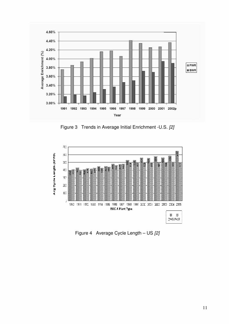
former ABB-Atom in Sweden. The designs of all companies mentioned above are offered world wide. Besides for some older plants today the international standard for PWR fuel assemblies is a 17x 17 fuel rod configuration, with the exception of the mainly in Germany operated newer PWR plants built by Siemens which are using an 18x18 fuel rod configuration. All fuel vendors claim that with the present design the fuel assemblies can reach up to 60 GWd/tU. However, in reality the majority of the commercially operated fuel – PWR and BWR - is discharged with burn-up of 40 to 45 GWd/tU. This holds for Europe as well for the US, as shown in figure 1 [1] and figure 2 [2]. Similarly Westinghouse claims [3] to have reached batch discharge burn-ups for PWR fuel of 50 GWd/tU. Along with the increasing burn-up the initial U-235 enrichment increased In fact in some plants initial enrichments already have been realized in PWR fuel that go up to the international limit for fabrication and transportation of 5% [4]. With this initial enrichment the discharge burn-up can be extended up to 65 GWd/tU [3]. Of course those high discharge burn-ups can only be realized with an adequately long exposure time as for example 5 one-year cycles [4]. While in Europe one-year cycle are still the normal case, in the US since many years there is a strong trend to much longer cycles as illustrated in figure 4 [2]. Of course the discussed increase to very high burn-up has to be accompanied by an adequate development of the core load strategies. So called Low Leakage Patterns are in use with PWR and BWR cores since already many years. The degree of low leakage depends on the magnitude of difference in reactivity between fresh and burnt fuel and may have to be reduced compared to traditional low leakage patterns. In figure 5 a schematic pattern for a 5-regions core is shown [4].
In the near future the above described high burn-up targets of up to 65 GWd/tU will not be exceeded easily, due to the fact that the internationally established limit of 5% enrichment for fabrication and transportation is reached. However, there are also other reasons for a halt of the development at this burn-up figure. On the one hand some "surprises" occurred during the last 10 years with regard to the operational behavior. They will be discussed in some detail later in this paper. Also some "traditional" operational problems could not really fully be solved up to now. This refers in particular to "grid-to-rod" fretting failures in PWR fuel assemblies as the result of vibrations. On the other hand there are open questions with regard to the safety behavior of high burn-up PWR fuel [5], e.g. the in the mean while broadly known question of conservative RIA-limits [6], and also some so far not yet broadly discussed questions in connection with the LOCA behavior of high burn-up fuel. Therefore a "digesting period" is expected as the discharge burn-up reaches the range of 65 GWd/tU within the next years. In the meanwhile a considerable amount of experience has been collected with the design, fabrication and the performance of MOX fuel in Europe, in particular in France with PWR fuel. As already mentioned this MOX fuel was designed by either Siemens or Framatome/Fragema and the experience is now reported as with Framatome-ANF fuel[7]. There was and is also some MOX fuel in German BWRs. However, the experience collected so far is negligible as compared with MOX fuel in PWRs. Some MOX PWR lead test assemblies have been designed BNFL and were irradiated in Switzerland with interesting data from PIE examination and from ramp test [8] . The over-all finding is that the reliability of MOX PWR fuel assemblies is as good as with UO2 PWR fuel assemblies. "No rod has ever failed for MOX-specific reasons. Moreover,

4
the release rates of fission products in the primary coolant were similar to those observed with defective UO2 fuel" [7]. The burn-up with individual MOX FAs has reached 54 GWd/tM. In France a "hybride" fuel management scheme with 28 UO2 FAs (3.7 % enriched) irradiated for four annual cycles and 16 MOX FAs (Pu content equivalent to 3.25 % UO2) for three annual cycles has been used for all reactors wit MOX fuel since 1994, with load-following conditions since 1995. Recently the maximum average Pu content was increased from 5.3 to 7.08 to allow the use of Pu coming from reprocessing of highly irradiated fuel. These MOX FAs are equivalent to a Uranium enrichment of 4.3w/o. The future perspectives of the French MOX fuel R&D programs aim for target burn-up of 70 GWd/t. For this ambitious target it is necessary to improve the current fuel production technology, concerning the (U,Pu)O2 as well as the design of the fuel rod and assembly structure.
PWR and BWR Fuel Designs
The main design targets of PWR and BWR fuel assemblies and their components for regular operation are:
��optimal performance reliability. This requires the integrity of the whole fuel assembly and in particular of the fuel rod.
��optimal neutron economics, ��high burn-up, ��optimal thermo-hydraulic performance, ��optimal mechanical interaction between the FA components and with the coolant, ��optimal chemical interaction with the coolant, i.e. corrosion and hydrogen
up-take,
Of course, any fuel design also has to fulfill all safety relevant criteria, like adequate behavior under LOCA and RIA conditions.
PWR Fuel Assembly and Component Design,
A modern PWR fuel assembly typically is characterized by the following design features for the main FA components:
��Tops Nozzle with reduced pressure drop ��High performance spacer grids with improved mechanical strength as well as
optimized coolant mixing capabilities ��Fuel rods with advanced cladding materials to meet high duty corrosion
resistance. ��Guide thimbles with optimized mechanical properties, reinforced dash pots and
improved corrosion resistance to control the amount of hydrogen uptake ��A bottom nozzle with integrated anti-debris filters which are optimized to a
maximum of debris resistance an a minimum of pressure drop
As an example in figure 6 the main design features of the French AFA 3G fuel assembly [9] are shown. There are more on the market that fulfill the same main design targets as
These are for example the "HTP" (High-thermal-Performance) Fuel Assembly of Framatome-ANP that comes from the Siemens development, and the RFA (Robust Fuel Assembly )design of Westinghouse. They all have optimized all FA components and materials to meet the above mentioned major design targets. As examples some of the most interesting components and design details are shortly described.
5
The HTP Spacer (Siemens development)
Figure 7 gives an impression of the design principles:
��line contact between spacer cell and fuel rod, four pairs of continuous lines support the fuel rod thus leading to a maximum fretting resistance by a large area of grid-to-rod contact,
��spiral channels for the coolant flow through the spacer cell provide an excellent long range coolant mixing after the spacer, thus keeping the temperatures between cladding tube and coolant low.
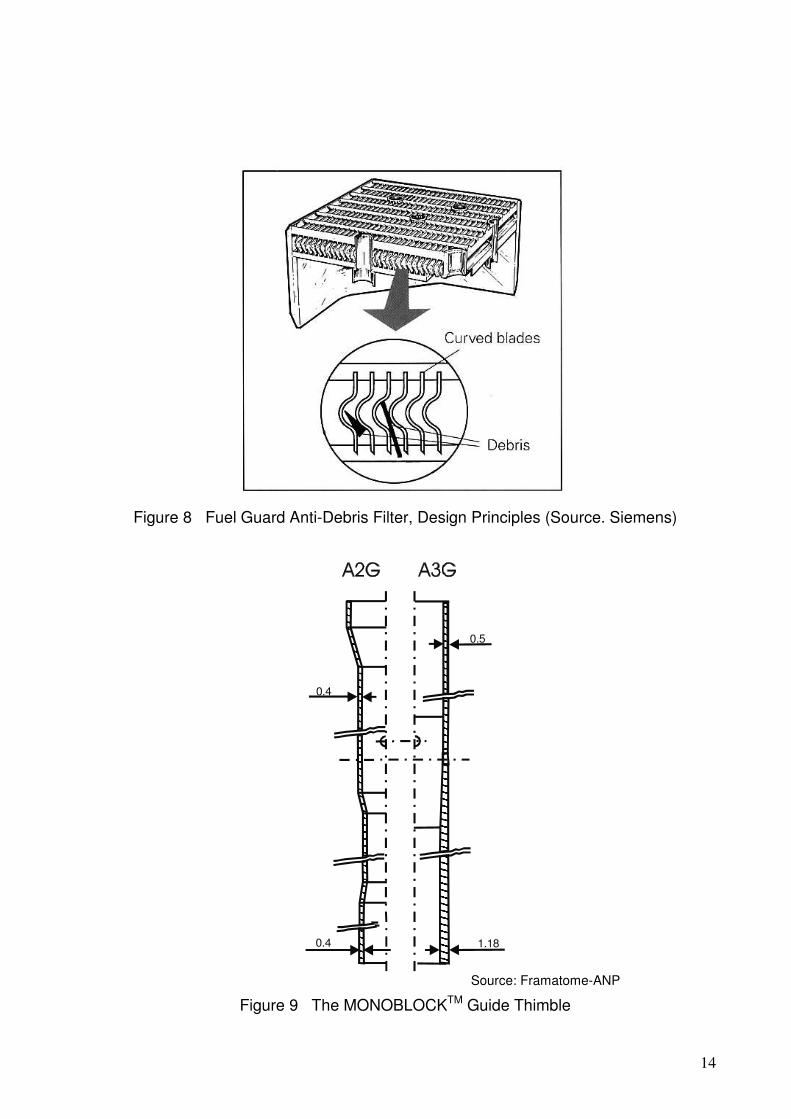
The Fuel Guard Anti-Debris Filter (Siemens development) Figure 8 shows the details of design principles:
��curved blades ��optimize the debris retention capability and ��minimize the pressure drop in the coolant
The MONOBLOCKTM Guide Thimble (Fragema/Framatome development) Figure 9 shows the design difference between this new guide thimble used in the AFA 3G, and the guide thimble used in the AFA 2G:
��the MONOBLOCKTM Guide Thimble is made from one piece, and the dashpot has no weld, thus improving the localized hydriding behavior
��the internal diameter and the wall thickness is increased, thus upgrading the lateral stiffness by about 30%
��the wall thickness of the dashpot is increased thus increasing the momentum of inertia and decreasing the stress in the dashpot which decreases the creep
��as the dashpot straightness is maintained the friction forces between absorber rod and guide thimble are drastically reduced.
More advanced FA designs are underway with both fuel suppliers:
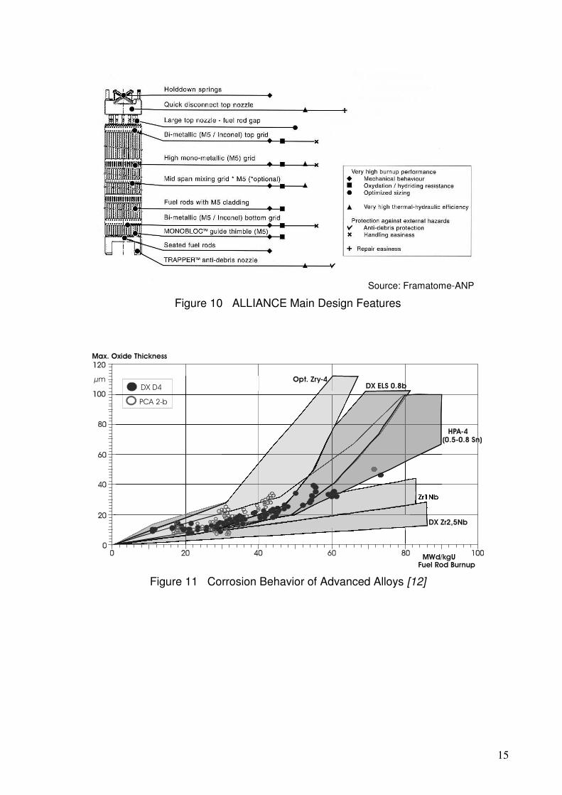
The "ALLIANCE" of Framatome-ANP [10], aiming at 70 GWd/tUor more with further improved thermo-hydraulic and mechanic performance. Figure 10 shows the main design features. Assemblies of this type are under irradiation : in the 14 ft version in a 1300 MW EdF reactor since 1999, in the 12 ft version in a 900 MW US reactor since 2000.
At Westinghouse development is going on leading beyond the design limits of the already mentioned RFA (Robust Fuel Assembly). This development aims at further increased heat transfer and burn-up. Various critical experiences in US plants where high heat flux in combination with crud deposition lead to fuel failures. This new dimension of critical operating conditions involves more thorough investigation of local sub-cooled boiling and the interaction with crud depositing coolant chemistry conditions. Therefore also more reliable prevention of crud deposition is one key to be able to up-rate the core power by increasing the heat flux over a wide range of burn-up.
PWR fuel materials
Material development was always a key feature in promoting PWR fuel design. Already 20 years ago it became clear that the classical Zircaloy could no longer fulfill the

6
function as a reliable cladding material for the increasing thermal load and burn-up requirements.
The critical design limiting property was the uniform corrosion with its strong temperature dependence at the interface cladding to coolant.
As a first consequence "improved Zircaloys" were developed with more strict limits for corrosion sensitive alloying elements and impurities and on heat treatment conditions. But soon more basic changes became unavoidable to meet the further increasing thermal and burn-up requirements.
This lead to strong efforts with all leading fuel designers to find advanced cladding material solutions. As a result today there are, besides many more experimental materials, three commercially used and proven variants of cladding material in use:
��The "Duplex" cladding with a low Sn Zry-variant on the outside and a regular Zircloy-4 as the bulk of the cladding wall. This Siemens development today is called DX-ELS 0.8 (Duplex-Extra-Low-Sn, with 0.8% Sn).
�� "ZIRLOTM", a 1% Nb,1% Sn,0.1% Fe material, developed by Westinghouse.
��"M5TM" an ZrNbO material, developed by Framatome/Fragema
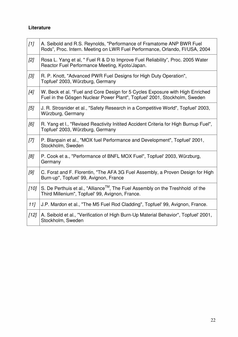
In figure 11 a comparison of the corrosion behavior of DX-ELS 0.8 and M5TM is given together with optimized Zry-4 and some other experimental materials is given. In figure 12 recent data [3] on the corrosion of ZIRLOTM is depicted.
Of course for the use in a modern PWR fuel design more data, e.g. on creep and growth, are necessary and available in the literature, e.g. on M5TM in [11] and for DX-ELS 0.8 in [12] . However, this would lead out of the limited scope of this paper.
In the meanwhile both PWR designer, as applicable, are going to introduce the above described advanced Zr-materials also into the FA structure, i.e. in spacer grids and guide thimbles. This has been announced by Framatome-ANP for the "ALLIANCETM" design with using the "M5TM"-material. And Westinghouse accordingly announces to use the ZIRLOTM-material for the structure of their advanced variant of the " RFA"-design.
BWR Fuel Assembly and Component Design,
The design of BWR fuel assemblies shows some typical differences to the design of a PWR fuel assembly:
��there are no guide thimbles, since in a BWR core there are control-crosses moving in between 4 fuel assemblies,
��there is a channel around each fuel assembly that avoids cross flow of the coolant in the fuel assembly,
��corrosion of Zr-alloy based components doe not play the very strong role as with PWR-FAs, since the temperature is constant in the whole area of boiling coolant.
��Due to several different initial enrichments in one bundle the homogenization of the thermal neutron flux in the bundle requires more design concern. This leads to additional water gaps in the bundle achieved by water channels or water rods and/or part length fuel rods in the bundle.
Today BWR fuel bundles have either 9x9 or 10x10 fuel rod configuration regardless of details in the mechanical design of the three already mentioned international BWR fuel suppliers.
7
An overall impression of the FA design of these three vendors is given in figure 13.
Today modern designs of BWR fuel assemblies use a 10x10 fuel rod configuration. However also 9x9 fuel rod configurations are still in use (from Global Nuclear Fuel and Framatome_ANP).
In figure 14 an example of a 10x10 fuel assembly designed by Global Nuclear Fuel (GE 12 ) is used to discuss the main components of the FA with regard to the design targets:
(1) Upper tie plate:
��reduces 2-phase pressure loss to improve stability and decrease pumping power
(2) Water rods:
��Improve moderation and fuel efficiency ��Enhance hot-to-cold reactivity wing
(3) Interactive channel:
��Increases moderator flow area ��Improves critical power performance ��Increases control rod clearance
(4) Inconel X750 Spacers
��Minimize pressure drop ��Enhance critical power performance (CPR) ��Restrain rod bow ��Control flow induced vibrations ��Resist corrosion
(5) Part-length fuel rods
��Reduce to-phase pressure drop ��Redistribute axial H/U ratio ��Optimize bundle uranium weight ��Improve cold shut down margins
(6) Lower tie plate
��Increase single phase pressure loss to improve stability ��Improve debris resistance
The above listed design targets hold in similar way also for the BWR fuel assemblies of the other vendors. Nevertheless there are some characteristic differences in the FA designs of those other vendors.
The design of Global Nuclear Fuel since the very first designs stays with a assembly structure design, where some fuel rods, the called tie rods, are fixed (screwed) to the upper and lower tie plate. Together with the spacer grids and now two water rods the fuel skeleton is built and the rest of the fuel rods is drawn into it, also being hold I – but not screwed to – the upper and the lower tie plate.
The same skeleton design principles are used in the 9x9 FA (Atrium 9) of Framatome-ANP. However in the 10x10 FA (Atrium 10) design a central water channel (replacing 3x3 fuel rods), together with the spacer grids and the upper and the lower tie plate, build the assembly skeleton. The fuel rods are not fixed to or held by the tie plates. They are held in the spacer grids only by friction forces thus being able to move within the

8
skeleton when axially growing under irradiation (“rods in basket design”). Part length rods are also used in the Atrium 10 fuel.
In the SVEA-96 design the channel divides the fuel rods into four sub-bundles (with spacer grids in each sub-bundle) using a double wall structure that forms an internal water cross (figure 15a) in the third generation of this design (SVEA-96 Optima) 8 part length rods are arranged around the water channel (figure 15b).
All vendors today are using specifically optimized spacer grids specifically optimized for low pressure drop and high coolant mixing capability. As an example the “ULTRAFLOW™“spacers grid of the Atrium 10 is shown in figure 16.
Also all vendors today have integrated anti-debris filters in the lower tie plate. One example used in the SVEA-96-Optima-2 design is shown in figure 17.
BWR fuel materials
One fuel behavior problem very typical for BWR fuel is the pellet-to-clad interaction phenomenon, PCI.
By chemo-mechanical interaction of the fuel pellets with the cladding tube during power changes and with the impact of iodine freshly escaping from the pellets stress corrosion cracking of the cladding tube made of Zircaloy has occurred quite frequently.
As a mitigating measure an internal liner was added to the ID of the cladding tube which is soft enough to absorb the iodine with just short cracks without attacking the main cladding tube turned out to be basically successful to avoid PCI defect of the fuel rods.
However, under certain conditions such liners have created very long axial cracks in the cladding leading to very severe fuel rod failures as a rest of secondary degradation. Experience has shown that the liner not only must be mechanically soft but also show sufficient corrosion resistance to avoid severe hydrogen uptake.
After a rather long time necessary to collect enough experience all three vendors have developed a liner that fulfills both condition. Global Nuclear Fuel use a so called “triclad”- design of the cladding tube, adding another internal corrosion resistant layer to the first liner. Framatome-ANP is using a Zr-0.4Fe liner [1], and Westinghouse is using a ZrSn liner.
LWR Fuel Operational Performance
A recently [2] given overview on the trends of fuel failures shows (figure 18) that during the decade of the 1990ies there was always the fuel failure rate of the PWR fuel higher than that of the BWR fuel but the trend was systematically decreasing for both. This has changed since 2000. While in 2002 –03 the PWR failure rate increased unexpectedly, the BWR failure rate continued to stay on very low level. The reason for that will be discussed in the next 2 sections.
PWR Performance
In figure 19 a very recently presented overview [2] on the trends of failure root causes in PWR fuel in the US is given. As already mentioned in the historical review, up to now Western PWR fuel could not reach the target of a failure rate of 10-6 or lower . On the one hand there are still fuel failures caused by debris fretting. In fact the anti-debris filters could decrease this problem significantly (figure 20). However, not all utilities are

9
using fuel with this device. Also the problem of spacer to cladding fretting could not be fully resolved. In detail the reasons for this kind of defects are different for different designs.
On the other side during the 90-ties also new types of fuel failures occurred that are correlated to a high heat flux in combination with crud deposition on the fuel rod surface. At locations where sub-cooled boiling occurs, i.e. on upper spans of high-power fuel assemblies the deposition is accelerated. Boric acid and LiOH also concentrate in these boiling crud deposits, accumulating boron compounds.
The result of this boron buildup in the upper portions of some fuel assemblies is that the core power distribution shifts unexpectedly toward the core inlet (several months after start-up of the cycle). This shift is called a "crud induced power shift" (CIPS), or "axial offset anomaly" (AOA) (Figure 21). In most cases CIPs incidents in the US occurred after the power output of the plant was increased. Under locally thick crud deposits the temperature at the interface between cladding surface and coolant increases, thus leading to accelerated localized corrosion.
As a result fuel rod failures occurred. Consequently more attention has to be paid to localized sub-cooling in advanced high duty PWR fuel designs.
BWR Performance
In figure 22 a very recently presented overview [2] on the trend of root causes in BWR in the US fuel is given. It shows that the majority of defects has been caused by corrosion related mechanism in combination with high fuel rod duty. The root cause so far could not be fully clarified because the analysis is complicated by coolant chemistry changes introduced in order to mitigate material degradation and dose control.
Improved debris filters could further be reduced defects caused by debris fretting.
Amazingly the failure rate due to PCI mechanism has increased again. This shows that the mitigating of this failure by improved cladding liner concepts was not yet fully satisfying.
Conclusions
This study shows that as well for PWR as for BWR fuel successful design development has been achieved even in the 5th decade of L’WR fuel development. Furthermore it appears that also in the future this development will go on resulting in even more improved reliability and economy of LWR fuel performance.

10
Figure 1 Evolution of the Discharge Burnup of FRAMATOME ANP BWR Fuel Assemblies and the Annual Fuel Rod Failure Rate [1]
Figure 2 Trends in Discharge-Average Burnup - U.S. [2]
11
Figure 3 Trends in Average Initial Enrichment -U.S. [2]
Figure 4 Average Cycle Length – US [2]

12
Figure 5 Schematic Loading Pattern of the 5-Region Core [4]

13
Source: Framatome/Fragema
Figure 6 AFA 3G Main Design Features
Source: Framatome-ANP/Siemens
Figure 7 HTP spacer, Design Principles
14
Figure 8 Fuel Guard Anti-Debris Filter, Design Principles (Source. Siemens)
0.4
0.4
0.5
1.18
Source: Framatome-ANP
Figure 9 The MONOBLOCKTM Guide Thimble
15
Source: Framatome-ANP
Figure 10 ALLIANCE Main Design Features
�� ����������� �������
��������������
�����
����������
� � !"#$%&'(�)* �+&��&�
� ,-���-. '�/0.1"�'22
�����
�����
Figure 11 Corrosion Behavior of Advanced Alloys [12]

16
Figure 12 Corrosion of ZIRLOTM vs. Zircaloy-4 at modified Fuel Duty [3]
Global Nuclear Fuel Westinghouse Framatome-ANP Source: vendors
Figure 13 Overall View of BWR Fuel Assemblies

17
1 upper tie plate
2 water rods
3 interactive channel
4 spacer grids
5 part-length fuel rods
6 lower tie plate
Source: Global Nuclear Fuel/GE
Figure 14 Details of BWR Fuel Assembly (GE 14)
a SVEA-96
b SVEA-96 Optimized Source Westinghouse/ABB
Figure 15 SVEA-96 Cross Sections

18
Source: Framatome-ANP
Figure 16 “ULTRAFLOW™“ spacer grid of Atrium 10
Source: Westinghouse/ABB
Figure 17 Anti-Debris Filter of SVEA-96 Optima-2

19
Figure 18 Trend in US Fuel Failure Rates [2]
Figure 19 Trend in US PWR Fuel Failure Root Causes [2]

20
100%
80
60
40
20
1988
*Basis: 1998 failure Rate = 100%
Percentage of fuel assemblies with anti-debris deviceNormalized figure* of fuel damaged by debris
1989 1990 1991 1992 1993 1994 1995 1996 1997 1998 1999 2000
Year
[Source: Framatome-ANP]
Figure 20 Impact of Anti-debris Filters on Fuel Failures Induced by Debris
Cycle Burnup (MWD/MTU)
Axi
al O
ffse
t (%
)
10
5
0
0 5000 10000 15000 20000
-5
-10
-15
Figure 21 Axial Offset Behavior for a CIPS Core [3]

21
Figure 22 Trend in US BWR Fuel Failure Root Causes [2]
22
Literature
[1] A. Seibold and R.S. Reynolds, "Performance of Framatome ANP BWR Fuel Rods”, Proc. Intern. Meeting on LWR Fuel Performance, Orlando, Fl/USA, 2004
[2] Rosa L. Yang et al, " Fuel R & D to Improve Fuel Reliability”, Proc. 2005 Water Reactor Fuel Performance Meeting, Kyoto/Japan.
[3] R. P. Knott, "Advanced PWR Fuel Designs for High Duty Operation", Topfuel' 2003, Würzburg, Germany
[4] W. Beck et al. "Fuel and Core Design for 5 Cycles Exposure with High Enriched Fuel in the Gösgen Nuclear Power Plant", Topfuel' 2001, Stockholm, Sweden
[5] J. R. Strosnider et al., "Safety Research in a Competitive World", Topfuel' 2003, Würzburg, Germany
[6] R. Yang et l., "Revised Reactivity Initited Accident Criteria for High Burnup Fuel", Topfuel' 2003, Würzburg, Germany
[7] P. Blanpain et al., "MOX fuel Performance and Development", Topfuel' 2001, Stockholm, Sweden
[8] P. Cook et a., "Performance of BNFL MOX Fuel", Topfuel' 2003, Würzburg, Germany
[9] C. Forat and F. Florentin, "The AFA 3G Fuel Assembly, a Proven Design for High Burn-up", Topfuel' 99, Avignon, France
[10] S. De Perthuis et al., "AllianceTM, The Fuel Assembly on the Treshhold of the Third Millenium", Topfuel' 99, Avignon, France.
11] J.P. Mardon et al., "The M5 Fuel Rod Cladding", Topfuel' 99, Avignon, France.
[12] A. Seibold et al., "Verification of High Burn-Up Material Behavior", Topfuel' 2001, Stockholm, Sweden

23
Figures
Fig. 1 Burnup distribution of Siemens PWR fuel with Burnups >40 MWd/tU (Status 12/2000) [1]
Fig. 2 Trends in Discharge-Average Burnup - U.S. [2]
Fig. 3 Trends in Average Initial Enrichment -U.S. [2]
Fig. 4 Trends in Cycle Length – US [2]
Fig. 5 Schematic Loading Pattern of the 5-Region Core [4]
Fig. 6 AFA 3G Main Design Features [9]
Fig. 7 HTP spacer, Design Principles [1]
Fig. 8 Fuel Guard Anti-Debris Filter, Design Principles [Source: Siemens]
Fig. 9 The MONOBLOCKTM Guide Thimble [9]
Fig. 10 AllianceTM Main Design Features [10]
Fig. 11 Corrosion Behavior of Advanced Alloys [12]
Fig. 12 Corrosion of ZIRLOTM vs. Zircaloy-4 at modified Fuel Duty [3]
Fig. 13 Overall View of BWR Fuel Assemblies [Source: vendors]
Fig. 14 Details of BWR Fuel Assembly (GE 14) [Source: Global Nuclear Fuel/GE]
Fig. 15 SVEA-96 Cross Sections [Source: Westinghouse/ABB]
Fig. 16 “ULTRAFLOW™“ spacer grid of Atrium 10 [Source: Framatome-ANP]
Fig. 17 Anti-debris Filter of SVEA-96 Optima-2 [Source: Westinghouse/ABB]
Fig. 18 Impact of anti-debris filters on fuel failures induced by debris [Source: Framatome-ANP]
Fig. 13 Axial Offset Behavior for a CIPS Core [3]
Fig. 14 Relation between Quality Assurance, Total Quality Management, and (Customer´s) Quality Awareness [13]
Fig. 15 Distribution of Quality Characteristics [14]
Fig. 16 The Three Stages of Quality Management in Modern Fuel Production [14]
Fig. 17 Development of Failure Cost Under the Influence of Process Control [17]
Fig. 18 Trend in US Fuel Failure Rates [2]

24
Fig. 19 Trend in US PWR Fuel Failure Root Causes [2]
Fig. 20 Impact of Anti-debris Filters on Fuel Failures Induced by Debris [Source: Framatome-ANP]
Fig. 21 Axial Offset Behavior for a CIPS Core [3]
Fig. 22 Trend in US BWR Fuel Failure Root Causes [2]