design and implementation of gsm based industrial …
TRANSCRIPT

i
DESIGN AND IMPLEMENTATION OF GSM BASED
INDUSTRIAL PROCESS MONITORING AND CONTROL
SYSTEM
Final year project report submitted to Kampala international university in partial fulfillment
of the requirement for the award
Of
Bachelor of Science in Electrical Engineering
by
ISABIRYE JAMES
1153-03114-03229
Email: [email protected]
Tel: (+256) 702829200 / (+256) 782373677
DEPARTMENT OF ELECTRICAL, TELECOMMUNICATION &
COMPUTER ENGINEERING
SCHOOL OF ENGINEERING & APPLIED SCIENCES
AUGUST 2019

i
DECLARATION
I hereby declare that to the best of my knowledge, the matter contained in this final year
project report is original, and has not been submitted for any academic award by any student
to any other University or Institution for the award of any Degree or Diploma.
................................................ ……. / …….. / 2019
Signature Date
ISABIRYE JAMES
REG. NO: 1153-03114-03229
Email: [email protected]
Tel: (+256) 702829200 / (+256) 782373677
ii
APPROVAL
This is to certify that this final year project report entitled, “DESIGN AND
IMPLEMENTATION OF GSM BASED INDUSTRIAL PROCESS MONITORING
AND CONTROL SYSTEM” submitted by Isabirye James (1153-03114-03229) in partial
fulfilment of the requirements for the award of Bachelor of Science degree in Electrical
Engineering at Kampala International University is an authentic work carried out by him
under our supervision and guidance and hereby recommend for examination and acceptance.
MR. ADABARA IBRAHIM
Signature…………………………… Date…………………………………
www.rootiancenter.com
www.eduraryschool.com

iii
DEDICATION
I am deeply indebted to my parents for their love, sacrifice, and support. My full dedication
to this work would have not been possible without their blessings and moral support. This
report is a dedication to them.

iv
ACKNOWLEDGMENT
First and foremost, I would like to give thanks to the Almighty God, the creator of the
Heaven and the Earth for giving me all the necessary strength, knowledge, and wisdom to
complete this project report.
I would like to express my sincere gratitude to my project supervisor, Mr. Adabara Ibrahim
for his patience, immense knowledge, motivation, and constant support. Their guidance has
helped me throughout my project work and in writing my report.
I would also like to thank all faculty members and staff of the Department of Electrical,
Telecommunication and Computer Engineering for their encouragement, and insightful
comments which helped me to complete this project.
In a special way, I thank Teddy Isabirye, my wife, Mr. and Mrs. Balunywa Baker, Mr. and
Mrs. Kayima D Daglas for the courage and financial support given to me during my course of
study and project implantation as well.
Finally, I would like to thank all my friends and especially my classmates for all the
discussions. I have greatly enjoyed their companionship during my stay at Kampala
International University.
v
TABLE OF CONTENTS
DECLARATION ........................................................................................................................ i
APPROVAL .............................................................................................................................. ii
MR. ADABARA IBRAHIM ..................................................................................................... ii
DEDICATION ......................................................................................................................... iii
ACKNOWLEDGMENT .......................................................................................................... iv
TABLE OF CONTENTS .......................................................................................................... v
LIST OF FIGURES ............................................................................................................... viii
LIST OF TABLES .................................................................................................................... ix
ABBREVIATIONS ................................................................................................................... x
ABSTRACT ............................................................................................................................ xii
CHAPTER ONE ........................................................................................................................ 1
INTRODUCTION ..................................................................................................................... 1
1.0 Introduction ...................................................................................................................... 1
1.1 Background ...................................................................................................................... 1
1.2 Problem Statement ........................................................................................................... 2
1.3 Objectives of the Project .................................................................................................. 2
1.3.1 Main Objective .......................................................................................................... 2
1.3.2 Specific Objectives ................................................................................................... 2
1.4 Research questions ........................................................................................................... 3
1.5 Significance of the project ............................................................................................... 3
1.6 Scope of the Project ......................................................................................................... 3
1.6.1 Content Scope ........................................................................................................... 3
1.6.2 Time Scope ............................................................................................................... 4
CHAPTER TWO ....................................................................................................................... 5
LITERATURE REVIEW .......................................................................................................... 5
2.0 Introduction ...................................................................................................................... 5
2.1 Existing Technologies ...................................................................................................... 5
2.1.1 Bluetooth Technology ............................................................................................... 5
2.1.2 ZigBee Technology ................................................................................................... 6

vi
2.1.3 Wi-Fi Technology ..................................................................................................... 6
2.2 GSM ................................................................................................................................. 7
2.3 GSM Competing with SCADA ........................................................................................ 9
2.4Overview of the Devices Used ........................................................................................ 11
2.4.1 LM35 ....................................................................................................................... 11
2.4.2 LCD JHD162A ....................................................................................................... 13
2.4.3 SIM300 .................................................................................................................... 15
2.4.4ATmega32 ................................................................................................................ 18
2.4.5 Relay ....................................................................................................................... 21
2.4.6Matrix Keypad ......................................................................................................... 22
2.4.7 Buzzer ..................................................................................................................... 22
2.4.8 Power Supply .......................................................................................................... 23
2.4.9 Software Module ..................................................................................................... 23
CHAPTER THREE ................................................................................................................. 24
METHODOLOGY .................................................................................................................. 24
3.0 Introduction .................................................................................................................... 24
3.1 System Model ................................................................................................................ 24
3.2 Basic Principle of System Model ................................................................................... 25
3.3 Working of System Model ............................................................................................. 25
3.4 Interfacing of Devices Used ........................................................................................... 27
3.4.1 LM35 interfacing with AVR Board ........................................................................ 27
3.4.2 Algorithm for ADC conversion with flowchart ...................................................... 27
3.4.3 LCD interfacing with AVR Board .......................................................................... 29
3.4.4 Writing commands in LCD in 4 bit mode ............................................................... 29
3.4.5 SIM300 interface with AVR Board ........................................................................ 31
3.4.6 Algorithm for checking the sim300 using PC ......................................................... 31
3.4.7 Flowchart for auto sending of inndussrial processes temperature update SMS ..... 32
3.4.8 System Flowchart .................................................................................................... 33
CHAPTER FOUR ................................................................................................................... 34
RESULTS AND DISCUSSION .............................................................................................. 34
4.0 Introduction .................................................................................................................... 34
4.1 System Evaluation .......................................................................................................... 34

vii
4.2 Results ............................................................................................................................ 35
4.3 Discussion ...................................................................................................................... 36
CHAPTER FIVE ..................................................................................................................... 38
CONCLUSION, RECOMMENDATION AND FUTURE SCOPE OF WORK .................... 38
5.0 Introduction .................................................................................................................... 38
5.1 Conclusion ..................................................................................................................... 38
5.2 Recommendation ........................................................................................................... 38
5.3 Future Scope .................................................................................................................. 39
REFERENCES ........................................................................................................................ 41
APPENDIX ............................................................................................................................. 43
Appendix A: Project Time-Frame ........................................................................................ 43
Appendix B: Project Budget ................................................................................................ 44

viii
LIST OF FIGURES
Figure 1: General architecture of a GSM network .......................................................................... 8
Figure 2: Plastic package LM35 DZ ............................................................................................. 12
Figure 3: Pin layout ....................................................................................................................... 12
Figure 4: Voltage outputs .............................................................................................................. 13
Figure 5: 16X2 LCD ..................................................................................................................... 14
Figure 6: LCD Block Diagram ...................................................................................................... 15
Figure 7: Overview of SIM300 ..................................................................................................... 16
Figure 8: Block diagram & pin configuration of SIM300 ............................................................ 17
Figure 9: AVR Development Board ............................................................................................. 18
Figure 10: Architecture of ATMEGA 32 ...................................................................................... 20
Figure 11: Pin configuration ......................................................................................................... 21
Figure 12: Relay ............................................................................................................................ 22
Figure 13: Matrix keypad .............................................................................................................. 22
Figure 14: Buzzer .......................................................................................................................... 23
Figure 15: AC-to-DC Conversion ................................................................................................. 23
Figure 16: System Model .............................................................................................................. 24
Figure 17: Total interfacing and circuit diagram .......................................................................... 26
Figure 18: Flowchart for ADC Conversion .................................................................................. 28
Figure 19: LCD 4 bit interface ...................................................................................................... 30
Figure 20: Flowchart for sending Message ................................................................................... 32
Figure 21: System Flowchart ........................................................................................................ 33
Figure 22: The temperature is continuously being displayed till it is below 50 degree................ 35
Figure 23: When the temp exceeds 50 degree .............................................................................. 35
Figure 24: Before sending SMS .................................................................................................... 35
Figure 25: After the SMS is successfully sent .............................................................................. 35
Figure 26: When the temperature once again falls back below 50°C ........................................... 36
Figure 27: Working model of GSM Based Industrial Process Monitoring and Control System .. 37
Figure 28: GSM to 3G technology ................................................................................................ 40
ix
LIST OF TABLES
Table 1: GSM characteristics .......................................................................................................... 7
Table 2: Comparing GSM with SCADA system .......................................................................... 10
Table 3: Pin configuration of LCD ............................................................................................... 14
Table 4: LM35 interfacing with AVR Board ................................................................................ 27
Table 5: LCD interfacing with AVR Board .................................................................................. 29
Table 6: SIM300 interface with AVR Board ................................................................................ 31
Table 7: Output results Obtained .................................................................................................. 36
Table 8: Project Time-Frame ........................................................................................................ 43
Table 9: Project Budget ................................................................................................................. 44
x
ABBREVIATIONS
3G 3rd Generation
ADC Analog-to-Digital Conversion
AT Attention
CDMA Code Division Multiple Access
CHI Computer Human Interface
EPROM Electrically Programmable Read-only Memory
FDMA Frequency Division Multiple Access
GMSK
IP
EDGE
SCADA
ADSL
CMOS
DC
ITU
I/O
2G
Gaussian Minimum Shift Keying
Internet Protocol
Enhanced Data rate for GPRS Evolution
Supervisory Control and Data Acquisition
Asynchronous Digital Subscriber Line
Complementary Metal Oxide Semiconductor
Direct Current
International Telecommunications Union
Input/Output
2nd Generation
GPRS General Packet Radio Service
GSM Global System for Mobile Communication
HMI Human Machine Interface
IEEE Institute of Electrical and Electronics Engineers
IR Infrared
LCD Liquid Crystal Display
MCU Microcontroller
MHz Mega Hertz
PLC Programmable Logic Controllers
RAM Read Only memory
RISC Reduced Instruction Set Computer
RISC Reduced Instruction Set Computer
RX Receiver
SIM Subscriber Identity Module

xi
SMS Short Message Service
SRAM Statistic Random Access Memory
TDMA Time Division Multiple Access
TX Transmitter
USART Universal Synchronous Asynchronous Receiver Transmitter
WLAN Wireless Local Area Network

xii
ABSTRACT
GSM Based Industrial Process Monitoring and Control System is a microcontroller
embedded system that is fully controlled by the 8-bit AVR Atmega32 microcontroller which
has 32KB of flash memory for the program data storage.
LM35 IC, GSM Modem, LCD screen, Relays (Process control devices), Matrix keypad are
interfaced with the microcontroller unit. The embedded system is designed with on board
power supply.
LM35 senses the temperature of the industrial processes and the readings are continuously
displayed on LCD and also sent wirelessly to the industrial operator’s mobile set.
The operator is able to control the status of the industrial process control devices by sending
pass worded SMS commands which are different for each process device. The system sends
feedback SMS notification about the status of the process control devices.
The overview of this report is as follows:
Chapter one-Introduction: It gives a brief introduction and background of this project.
Chapter two-Literature review: It gives an overview of the existing technologies and
devices used.
Chapter three-Methodology: It explains the system design i.e. architecture and interfacing
of the devices used.
Chapter four-Results and discussion: Describes the results and output of the system.
Chapter five-Conclusions and Future Scope: It gives the conclusions drawn from this
project and brief ideas about future development works that can be undertaken.

1
CHAPTER ONE
INTRODUCTION
1.0 Introduction
This chapter gives a brief introduction and background of this project.
1.1 Background
Industrial monitoring and control is the use of sensor technology and control systems
such as computers to control industrial machinery and processes, reducing the need for
human intervention hence increasing safety. In the scope of industrialization,
monitoring and control is a step beyond mechanization. Whereas mechanization
provided human operators with machinery to assist them with the physical requirements
of work, monitoring and control greatly reduces the need for human sensory and mental
requirements as well. Processes and systems can also be monitored and controlled.
Engineers strive to combine automated devices with mathematical and organizational
tools to create complex systems for a rapidly expanding range of applications and
human activities.
Many roles for humans in industrial processes presently lie beyond the scope of
automation. Human-level pattern recognition, language recognition, and language
production ability are well beyond the capabilities of modern mechanical and computer
systems. Tasks requiring subjective assessment or synthesis of complex sensory data,
such as scents and sounds, as well as high-level tasks such as strategic planning,
currently require human expertise. In many cases, the use of humans is more cost-
effective than mechanical approaches even where automation of industrial tasks is
possible.
Specialized hardened computers, referred to as programmable logic controllers (PLCs),
are frequently used to synchronize the flow of inputs from (physical) sensors and events
with the flow of outputs to actuators and events. This leads to precisely controlled
actions that permit a tight control of almost any industrial process.
Human-machine interfaces (HMI) or computer human interfaces (CHI), formerly
known as man-machine interfaces, are usually employed to communicate with PLCs
2
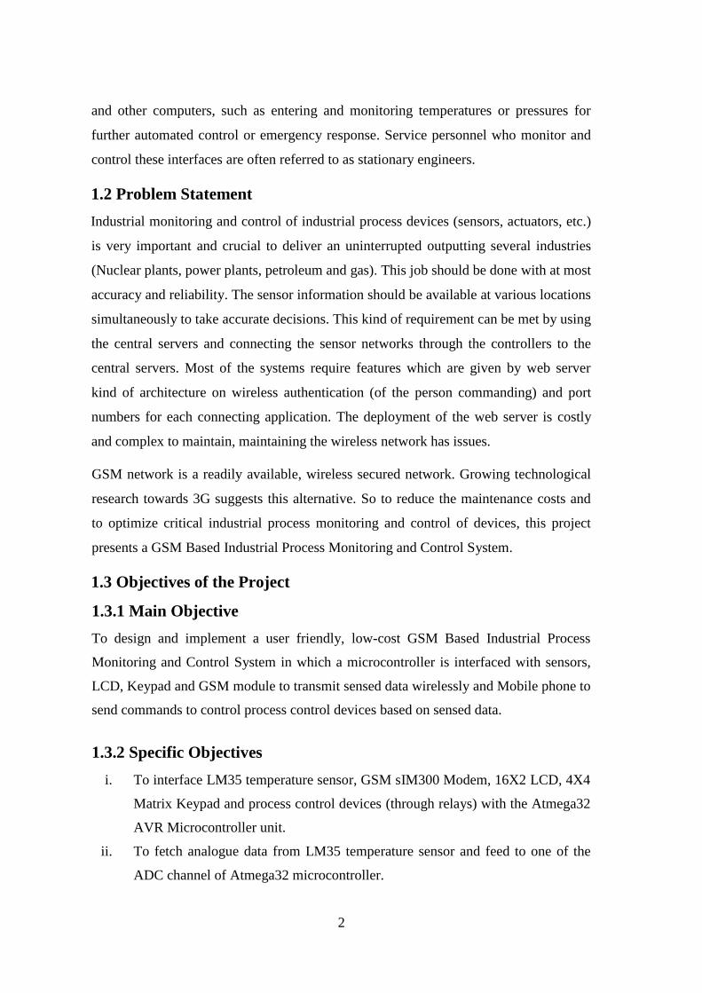
and other computers, such as entering and monitoring temperatures or pressures for
further automated control or emergency response. Service personnel who monitor and
control these interfaces are often referred to as stationary engineers.
1.2 Problem Statement
Industrial monitoring and control of industrial process devices (sensors, actuators, etc.)
is very important and crucial to deliver an uninterrupted outputting several industries
(Nuclear plants, power plants, petroleum and gas). This job should be done with at most
accuracy and reliability. The sensor information should be available at various locations
simultaneously to take accurate decisions. This kind of requirement can be met by using
the central servers and connecting the sensor networks through the controllers to the
central servers. Most of the systems require features which are given by web server
kind of architecture on wireless authentication (of the person commanding) and port
numbers for each connecting application. The deployment of the web server is costly
and complex to maintain, maintaining the wireless network has issues.
GSM network is a readily available, wireless secured network. Growing technological
research towards 3G suggests this alternative. So to reduce the maintenance costs and
to optimize critical industrial process monitoring and control of devices, this project
presents a GSM Based Industrial Process Monitoring and Control System.
1.3 Objectives of the Project
1.3.1 Main Objective
To design and implement a user friendly, low-cost GSM Based Industrial Process
Monitoring and Control System in which a microcontroller is interfaced with sensors,
LCD, Keypad and GSM module to transmit sensed data wirelessly and Mobile phone to
send commands to control process control devices based on sensed data.
1.3.2 Specific Objectives
i. To interface LM35 temperature sensor, GSM sIM300 Modem, 16X2 LCD, 4X4
Matrix Keypad and process control devices (through relays) with the Atmega32
AVR Microcontroller unit.
ii. To fetch analogue data from LM35 temperature sensor and feed to one of the
ADC channel of Atmega32 microcontroller.

3
iii. To display the temperature sensed reading and process control device status on
LCD screen which is pre-processed and calculated by ATmega32.
iv. To send the measured temperature to distant user wirelessly with the help of
GSM module (SIM 300) Via SMS.
v. To send commands through user’s mobile phone to control the process control
devices based on sensed sensor readings.
vi. To test and implement the GSM Based Industrial Process Monitoring and
Control System.
1.4 Research questions
i. How the industrial monitor controls the industrial process
ii. How the industrial monitor operates in the industrial process with the help of a
GSM?
iii. How important is the LCD screen and Atmega 32?
iv. How useful the GSM module is via SMS?
v. How helpful; sensors are via the mobile phone
vi. How a microcontroller helps in the industrial monitoring to control the industrial
process via the wireless network?
1.5 Significance of the project
Industrial and Factory process monitoring and control delivers increased
productivity and improves product quality.
It also presents real-time data that helps in making informed decisions.
1.6 Scope of the Project
1.6.1 Content Scope
The scope includes connecting the different industrial process control systems to relays
for controlling the industrial environment complex tasks like nuclear plants and reactors
in the industry. A GSM server is implemented with AVR Atmega32 chip, sensors and
relays. The GSM Modem can provide the necessary data related to the industry to a
maintenance officer located anywhere at any time. According to data received officer

4
will take some action by sending some AT commands to Atmega32 chip through
mobile unit to GSM modem. Atmega32 chip decodes the commands and controls the
industrial process devices through relays.
1.6.2 Time Scope
The project took approximately four months from inception stage to its full completion.
For details (Refer to appendix).

5
CHAPTER TWO
LITERATURE REVIEW
2.0 Introduction
This chapter discusses an overview of the existing technologies and devices used
2.1 Existing Technologies
Majority of the companies in developing countries have not implemented Automation
practices in industry. Except few large industries majority of the companies cannot
afford to invest huge amount of money in the existing costly setups to meet the
requirements of Industrial Automation.
Existing methods widely use the following technologies to communicate the
information from one end to the other end of the company.
Using Bluetooth -- But it is limited to short range.
Using ZigBee/ IEEE802.15.4 -- Range is up to only few Kilometres maximum.
Using Wi-Fi -- Requires costly equipment setup and high power consumption.
All the methods discussed above are quite expensive and complex to implement and not
very reliable. The availability of information at various nodes simultaneously is not
achieved.
2.1.1 Bluetooth Technology
Bluetooth Technology is a radio frequency (RF)-based, short-range connectivity
technology that promises to change the face of computing and wireless communication.
It is designed to be an inexpensive, wireless networking system for all classes of
portable devices. The projected cost of the Radio chip was around $5.
A complete Bluetooth system will require these elements:
An RF portion for receiving and transmitting data includes short-range radio
transceiver, an external antenna, and a clock reference (required for
synchronization)
A module with a baseband microprocessor

6
Memory
An interface to the host device (such as a mobile phone)
Its normal range of operation is 10m (at 1mW transmit power) and can be increased up
to 100m by increasing the transmit power to 100mW. The system operates in
unlicensed 2.4 GHz frequency band, hence it can be used worldwide without any
licensing issues. It provides an aggregate bit rate of approximately 1Mbps.
2.1.2 ZigBee Technology
The ZigBee radio specification is designed for low cost and power consumption than
Bluetooth. The specification is based on IEEE 802.15.4 standard. The radio operates in
the same ISM band as Bluetooth and is capable of connecting 255 devices per network.
The specification supports data rates of up to 250Kbps at a range of up to 30m. These
data rates are slower than Bluetooth, but in exchange the radio consumes significantly
with low power with a large transmission range. The goal of ZigBee is to provide radio
operation for months or years without recharging, thereby targeting applications such as
sensor networks and inventory tags.
The beauty of ZigBee is that devices from different manufacturers will be able to work
together, as long as all are compliant to the standard. It has been suggested that the
name evokes the haphazard paths that bees follow as they harvest pollen, similar to the
way packets would move through a mesh network.
ZigBee is standardized at two levels – the radio chips must follow certain design rules,
and the protocol layers that actually make the network function are defined and
controlled by the ZigBee Alliance. Advantages are: Reliable and self-healing, Supports
large number of nodes, Easy to deploy, Very long battery life, Secure and Low cost.
2.1.3 Wi-Fi Technology
Wi-Fi is the name given by the Wi-Fi Alliance to the IEEE 802.11 suite of standards.
802.11 defined the initial standard for wireless local area networks (WLANs).
But because of its costly equipment setup and high power consumption this technology
is not preferred.

7
2.2 GSM
GSM (Global System for Mobile communication) is a digital mobile telephone system
that is widely used in Europe and other parts of the world. GSM uses a variation of
Time Division Multiple Access (TDMA) and is the most widely used of the three
digital wireless telephone technologies (TDMA, GSM, and CDMA). GSM digitizes and
compresses data, then sends it down a channel with two other streams of user data, each
in its own time slot. It operates at either the 900 MHz or 1,800 MHz frequency band.
GSM is an international digital cellular telecommunication. The GSM standard was
released by ETSI (European Standard Telecommunication Standard) back in 1989. In
less than ten years since the first GSM network was commercially launched, it became,
the world’s leading and fastest growing mobile standard, spanning over 190 countries.
Table 1:GSM characteristics
Mobile Frequency Range RX: 925-960; TX: 880-915
Multiple Access Method TDMA/FDMA
Duplex Method FDD
Number of Channels 124 (8 users per channel)
Channel Spacing 200kHz
Modulation GMSK (0.3 Gaussian Filter)
Channel Bit Rate 270.833Kb
Global System for Mobile (GSM) is a second generation cellular standard developed to
deliver high quality and secure mobile voice and data services (such as SMS/ Text
Messaging) with full roaming capabilities across the world using digital modulation. It
is known as 2G digital which has a maximum data speed of 9.6Kbps and is based on
circuit switched technology and provides short message service (SMS).
The GSM network can be divided into three broad parts. The subscriber carries the
Mobile Station. The Base Station Subsystem controls the radio link with the Mobile
Station. The Network Subsystem, the main part of which is the Mobile services
8
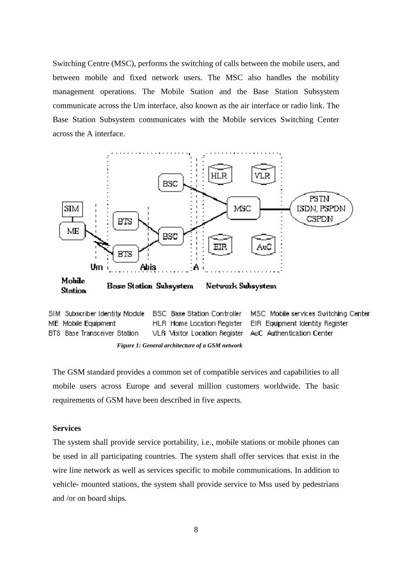
Switching Centre (MSC), performs the switching of calls between the mobile users, and
between mobile and fixed network users. The MSC also handles the mobility
management operations. The Mobile Station and the Base Station Subsystem
communicate across the Um interface, also known as the air interface or radio link. The
Base Station Subsystem communicates with the Mobile services Switching Center
across the A interface.
The GSM standard provides a common set of compatible services and capabilities to all
mobile users across Europe and several million customers worldwide. The basic
requirements of GSM have been described in five aspects.
Services
The system shall provide service portability, i.e., mobile stations or mobile phones can
be used in all participating countries. The system shall offer services that exist in the
wire line network as well as services specific to mobile communications. In addition to
vehicle- mounted stations, the system shall provide service to Mss used by pedestrians
and /or on board ships.
Figure 1: General architecture of a GSM network

9
Quality of Services and Security
The quality for voice telephony of GSM shall be at least as good as the previous analog
systems over the practical operating range. The system shall be capable of offering
information encryption without significantly affecting the costs to users who do not
require such facility.
Radio Frequency Utilization
The system shall permit a high level of spectrum efficiency and state-of-the-art
subscriber facilities. The system shall be capable of operating in the entire allocated
frequency band, and co-exist with the earlier systems in the same frequency band.
Network
The identification and numbering plans shall be based on relevant ITU
recommendations. An international standardized signalling system shall be used for
switching and mobility management. The existing fixed public networks should not be
significantly modified.
Cost
The system parameters shall be chosen with a view to limiting the cost of the complete
system.
2.3 GSM Competing with SCADA
SCADA (Supervisory Control and Data Acquisition) systems are currently widely used
in unmanned substations. The systems use wired communication mode including
setting up cables or fibre-optic cables or renting telephone lines or ADSL from
Telecommunication Corporations. However, it is not feasible to build SCADA systems
for prefabricated substations, because of the great difficulties to setting up wired
network to the remote areas and the high operating and construction cost.
10
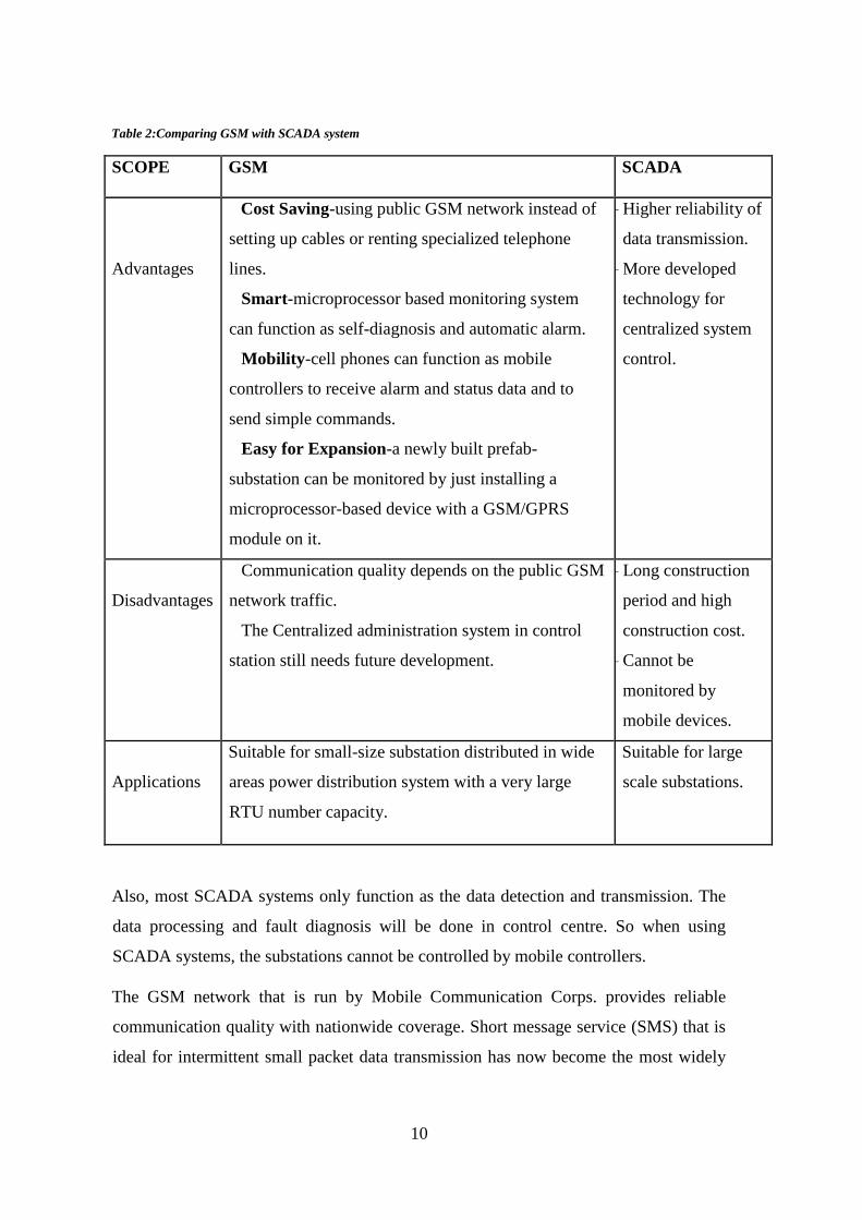
Table 2:Comparing GSM with SCADA system
SCOPE GSM SCADA
Advantages
– Cost Saving-using public GSM network instead of
setting up cables or renting specialized telephone
lines.
– Smart-microprocessor based monitoring system
can function as self-diagnosis and automatic alarm.
– Mobility-cell phones can function as mobile
controllers to receive alarm and status data and to
send simple commands.
– Easy for Expansion-a newly built prefab-
substation can be monitored by just installing a
microprocessor-based device with a GSM/GPRS
module on it.
– Higher reliability of
data transmission.
– More developed
technology for
centralized system
control.
Disadvantages
– Communication quality depends on the public GSM
network traffic.
– The Centralized administration system in control
station still needs future development.
– Long construction
period and high
construction cost.
– Cannot be
monitored by
mobile devices.
Applications
Suitable for small-size substation distributed in wide
areas power distribution system with a very large
RTU number capacity.
Suitable for large
scale substations.
Also, most SCADA systems only function as the data detection and transmission. The
data processing and fault diagnosis will be done in control centre. So when using
SCADA systems, the substations cannot be controlled by mobile controllers.
The GSM network that is run by Mobile Communication Corps. provides reliable
communication quality with nationwide coverage. Short message service (SMS) that is
ideal for intermittent small packet data transmission has now become the most widely

11
used value added service based upon GSM standard. Meanwhile, the decreasing cost of
GSM network devices such as mobile phones and GSM module has made them an
attractive option for other wireless communication applications. By utilizing GSM SMS
and assigning a unique address (SIM card number) to each remote control unit, data and
commands can be transmitted in the wireless communication network. This paper
presents design and implementation of a distributed monitoring and centralized
controlling system for prefabricated substations. The system completely meets the
demand of low cost and high level automation by introducing the microprocessor based
RTUs and mobile communication technology.
GPRS supports world’s leading packet based internet protocols that makes highly
efficient use of radio spectrum and enables high data speed. It enables any exiting IP or
X.25 application to operate over a GSM cellular connection. Its data speed varies from
115Kbps to 117Kbps but it is likely to average at 56Kbps.
It was developed to enable GSM operators to meet the following key features:
It is a step towards 3G.
Higher bandwidth and therefore data speed.
Seamless, immediate and continues connection to the internet—‘always on-line’.
New text and visual data content services.
Packet switched rather than circuit switched which enable higher radio spectrum
efficiency.
2.4Overview of the Devices Used
2.4.1 LM35
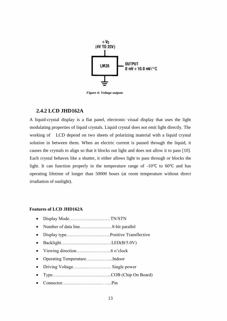
The LM35 series are precision integrated-circuit temperature sensors. Its output voltage
is linearly proportional to the Celsius temperature for a large range of temperature
values. The LM35 thus has an upper hand over linear temperature sensors calibrated in
° Kelvin, as the user is not required to subtract a large constant voltage from its output
to obtain convenient Centigrade scaling. The LM35 need not use any external
calibration or trimming to provide usual accuracies of ±1⁄4°C at room(moderate)
temperature and ±3⁄4°C over a full −55 to +150°C temperature range [5].

12
Features of LM35
Calibrated directly in ° Celsius (Centigrade)
Linear + 10.0 mV/°C scale factor
0.5°C accuracy guarantee (at +25°C)
Rated for full −55° to +150°C range
Suitable for remote applications
Low cost due to wafer-level trimming
Operates from 4 to 30 volts
Less than 60 μA current drain
Low self-heating, 0.08°C in still air
Nonlinearity only ±1⁄4°C typical
Low impedance output, 0.1 W for 1 mA load[ 5 ]
Figure 2: Plastic package LM35 DZ
Figure 3: Pin layout
13
2.4.2 LCD JHD162A
A liquid-crystal display is a flat panel, electronic visual display that uses the light
modulating properties of liquid crystals. Liquid crystal does not emit light directly. The
working of LCD depend on two sheets of polarizing material with a liquid crystal
solution in between them. When an electric current is passed through the liquid, it
causes the crystals to align so that it blocks out light and does not allow it to pass [10].
Each crystal behaves like a shutter, it either allows light to pass through or blocks the
light. It can function properly in the temperature range of -10℃ to 60℃ and has
operating lifetime of longer than 50000 hours (at room temperature without direct
irradiation of sunlight).
Features of LCD JHD162A
Display Mode………………………TN/STN
Number of data line…………………8-bit parallel
Display type………………………..Positive Transflective
Backlight……………………………LED(B/5.0V)
Viewing direction…………………..6 o’clock
Operating Temperature……………...Indoor
Driving Voltage……………………. Single power
Type………………………………...COB (Chip On Board)
Connector……………………… …..Pin
Figure 4: Voltage outputs

14
Driving method……………………..1/16 duty,1/5 bias
Display construction………………..16 Characters * 2 Lines
Figure 5: 16X2 LCD
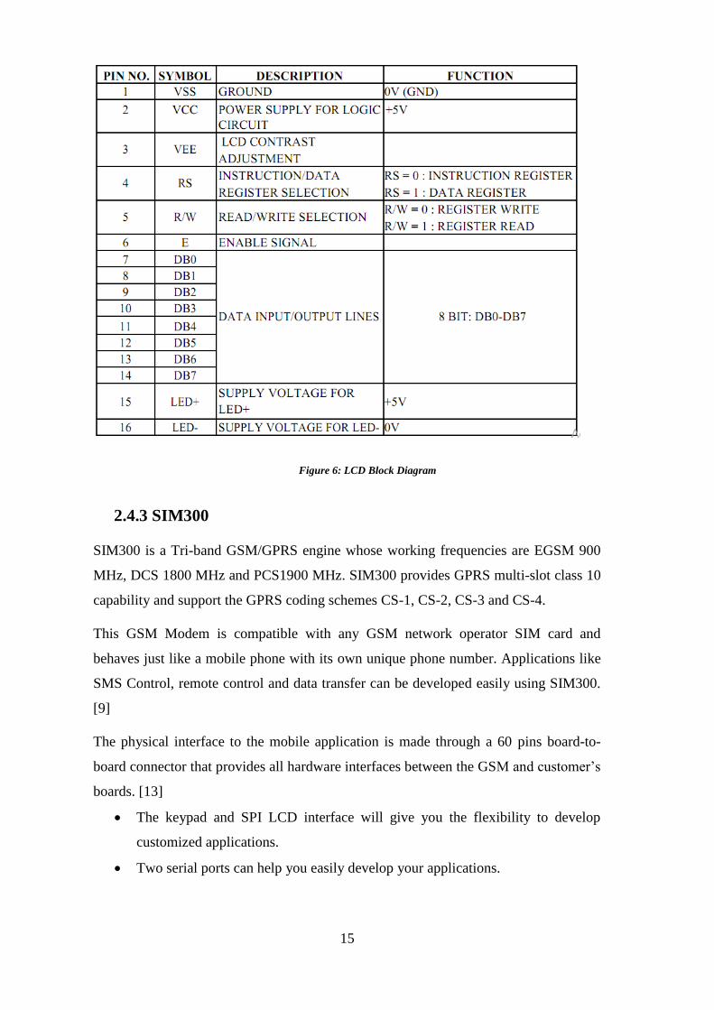
Table 3: Pin configuration of LCD
15
2.4.3 SIM300
SIM300 is a Tri-band GSM/GPRS engine whose working frequencies are EGSM 900
MHz, DCS 1800 MHz and PCS1900 MHz. SIM300 provides GPRS multi-slot class 10
capability and support the GPRS coding schemes CS-1, CS-2, CS-3 and CS-4.
This GSM Modem is compatible with any GSM network operator SIM card and
behaves just like a mobile phone with its own unique phone number. Applications like
SMS Control, remote control and data transfer can be developed easily using SIM300.
[9]
The physical interface to the mobile application is made through a 60 pins board-to-
board connector that provides all hardware interfaces between the GSM and customer’s
boards. [13]
The keypad and SPI LCD interface will give you the flexibility to develop
customized applications.
Two serial ports can help you easily develop your applications.
Figure 6: LCD Block Diagram

16
Two audio channels i.e. two microphones inputs and two speaker outputs are
present. This can be easily accessed by AT command.
Features of SIM300
Single supply voltage of 3.4V – 4.5V.
Typical power consumption in SLEEP mode to 2.5mA
SIM300 works in Tri-band: EGSM 900, DCS 1800, and PCS 1900.
Normal operation in temperature range of -20°C to +55°C
Stores SMS in SIM card
External Antenna is connected via 50 Ohm antenna connector or antenna pad.
It has two serial interfaces.
Timer function is programmable via AT commands.
Figure 7: Overview of SIM300

17
Figure 8: Block diagram & pin configuration of SIM300
18
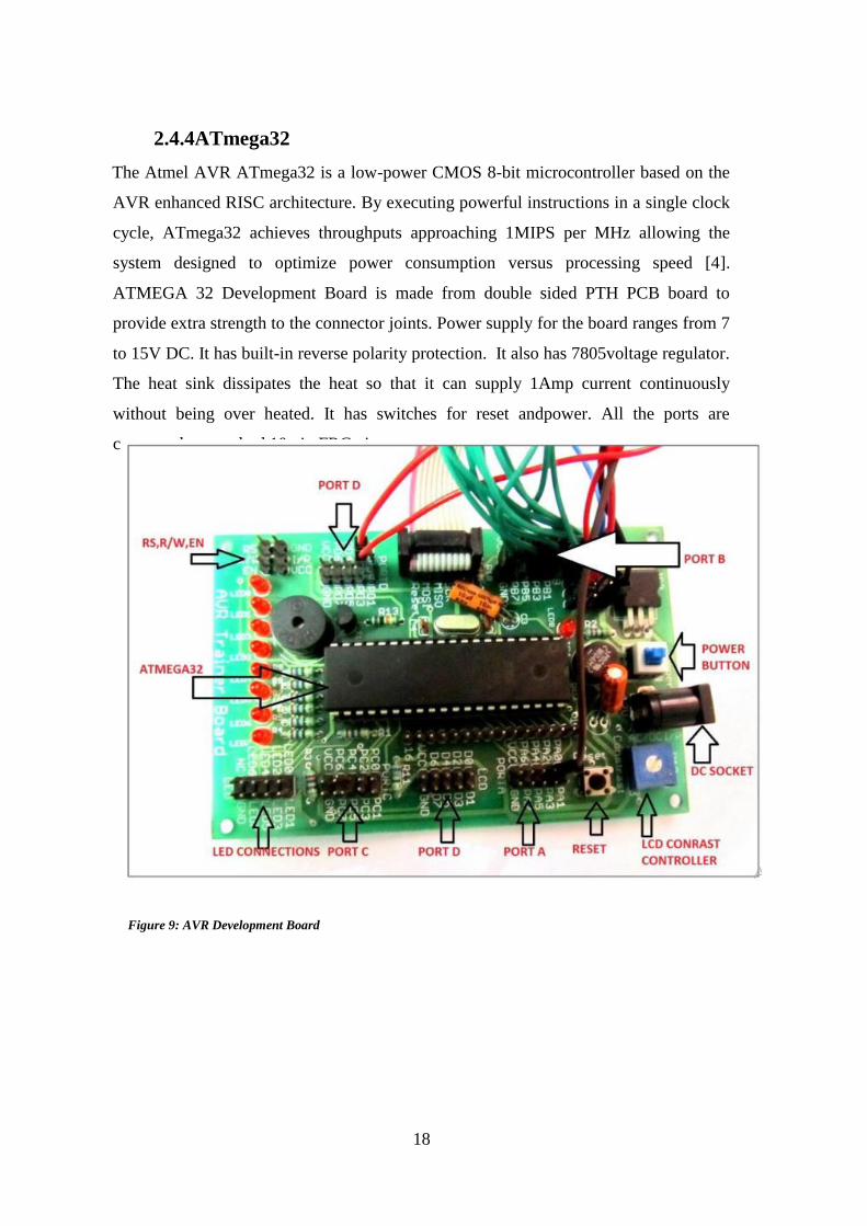
2.4.4ATmega32
The Atmel AVR ATmega32 is a low-power CMOS 8-bit microcontroller based on the
AVR enhanced RISC architecture. By executing powerful instructions in a single clock
cycle, ATmega32 achieves throughputs approaching 1MIPS per MHz allowing the
system designed to optimize power consumption versus processing speed [4].
ATMEGA 32 Development Board is made from double sided PTH PCB board to
provide extra strength to the connector joints. Power supply for the board ranges from 7
to 15V DC. It has built-in reverse polarity protection. It also has 7805voltage regulator.
The heat sink dissipates the heat so that it can supply 1Amp current continuously
without being over heated. It has switches for reset andpower. All the ports are
connected to standard 10 pin FRC pins.
Figure 9: AVR Development Board

19
Features of AVR Microcontrollers (ATMEGA-32)
32K bytes of ISP Flash Program memory with Read-While-Write capabilities.
1Kbyte EEPROM.
A programmable Watchdog Timer with Internal Oscillator.
2K byte SRAM.
32 general purpose I/O lines.
32 general purpose working registers.
A JTAG interface is available.
On-chip debugging support and programming.
Timer/Counters with compare modes.
A serial programmable USART.
A byte oriented Two-wire Serial Interface.
An 8-channel, 10-bit ADC.
An SPI serial port.
6 software selectable power saving modes [4]
20
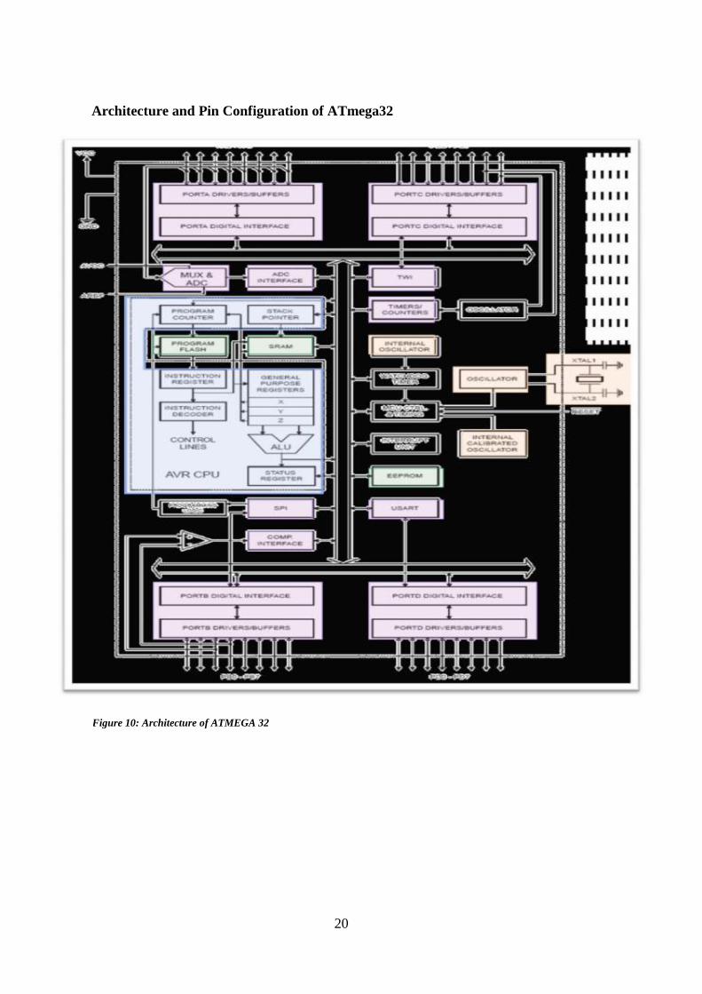
Architecture and Pin Configuration of ATmega32
Figure 10: Architecture of ATMEGA 32

21
2.4.5 Relay
Relay is an electromagnetic switchbased on electromagnetic induction used to control
the switching of an electrical device. The relay’s switch connections are labelled COM,
NC and NO
COM = Common, it is the moving part of the switch.
NC = Normally Closed, when the relay coil is off then the COM is connected to the
NC.
NO = Normally Open, when the relay coil is on then the COM is connected to the NO.
Figure 11: Pin configuration

22
This project uses 12V DC relays to control the switching on and offof the industrial
process loads.
2.4.6Matrix Keypad
A Matrix keypad consists of a set of pushbuttons which are interconnected. In this
project, a 4X4 matrix keypad in which there are 4 rows and 4 columns is used.
2.4.7 Buzzer
A piezoelectric buzzer/beeper is used in this project because of its portability and low
power consumption. The buzzer beeps in case of a wrong system start-up password
input to alert the authorities.
Figure 12: Relay
Figure 13: Matrix keypad

23
2.4.8 Power Supply
The microcontroller and other devices get power supply from AC to Dc adapter through
7805, 5 volts regulator. The adapter output voltage will be 12V DC non-regulated. The
7805/7812 voltage regulators are used to convert 12 V to 5V/12V DC.
2.4.9 Software Module
The program is written in Embedded C in AVR Studio 4. AVR Studio is an Integrated
Development Environment (IDE) to write and debug AVR applications in Windows
based operating systems; ex windows 8. AVR Studio provides a project management
tool, simulator, assembler and source file editor for C/C++, emulation, programming
and on-chip debugging .The project in AVR Studio is created under AVR GCC type.
The AVR GCC plug-in is a GUI front-end to GNU make and avr-gcc. The build and
run tool is WINAVR tool is used to convert C Language to HEX File. The HEX file is
dumped into the ATmega32 microcontroller using SinaProg 1.3.5.6. [6]
Figure 14: Buzzer
DC Output AC Power
AC/DC
Adapter
Regulator
(7805)
Filter
Figure 15: AC-to-DC Conversion
24
CHAPTER THREE
METHODOLOGY
3.0 Introduction
This chapter will explain the system design i.e. architecture and interfacing of the
devices used in this project.
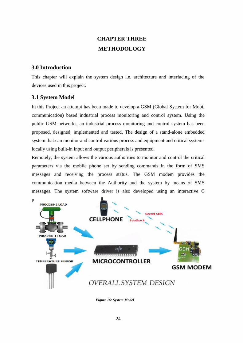
3.1 System Model
In this Project an attempt has been made to develop a GSM (Global System for Mobil
communication) based industrial process monitoring and control system. Using the
public GSM networks, an industrial process monitoring and control system has been
proposed, designed, implemented and tested. The design of a stand-alone embedded
system that can monitor and control various process and equipment and critical systems
locally using built-in input and output peripherals is presented.
Remotely, the system allows the various authorities to monitor and control the critical
parameters via the mobile phone set by sending commands in the form of SMS
messages and receiving the process status. The GSM modem provides the
communication media between the Authority and the system by means of SMS
messages. The system software driver is also developed using an interactive C
programming language platform.
Figure 16: System Model

25
3.2 Basic Principle of System Model
Atmega32 Microcontroller is interfaced with sensors, actuators, LCD display
and with GSM modem.
Atmega32 Microcontroller is programmed with the default control algorithm.
The sensor information processed by the controller can be rooted to the users
by power on controller sends status SMS to predefined numbers
User can update the control algorithm by sending an SMS.
User can get the status and change mode also by sending SMS.
Modem performs the operation and gives acknowledgment message to the
user.
3.3 Working of System Model
Micro controller is interfaced with sensors like Temperature, IR, Smoke sensors and
actuators that control industrial processes. The basic idea of these sensors is to monitor
the parameters of various systems. For example monitoring the boiler performance in a
thermal / Nuclear power plant can be done by using Temperature of the boiler. If any
increase in the temperature of the system beyond the threshold has been recorded, the
controller is instructed to initiate a corrective action. At the initial phase the controller
will send an SMS to the authorised user. Based on the information received the user can
initiate the corrective action. In the above case the temperature can be brought down by
controlling the heat input. The same instruction will be initiated by the user. After
receiving the corrective command, the controller will activate the necessary modules to
reduce the heat input.
The basic functionality of the smoke sensors is to control the parameters of the process
based on the external parameters and uncontrolled combustion happening, because of
the malfunction and break down of certain combustion process.
26
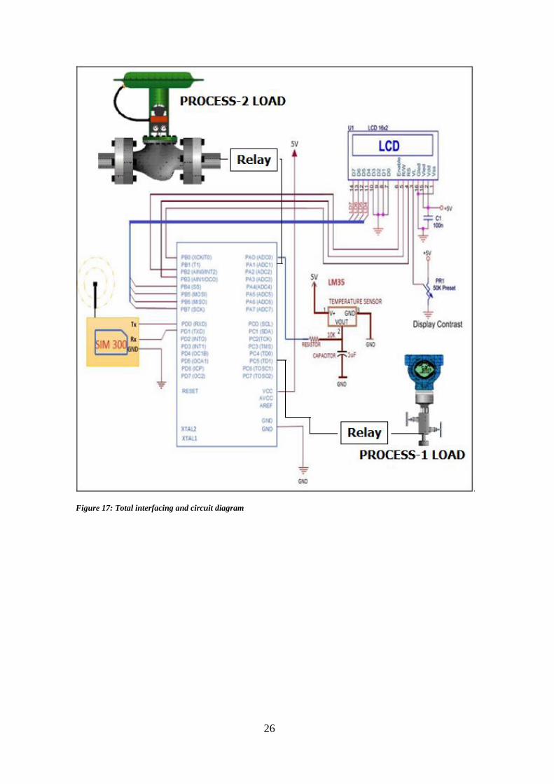
Figure 17: Total interfacing and circuit diagram

27
3.4 Interfacing of Devices Used
3.4.1 LM35 interfacing with AVR Board
3.4.2 Algorithm for ADC conversion with flowchart
The output of LM35 linearly varies with temperature.
The output is in 10MilliVolts per degree centigrade.
The ADC gives an output in the range of 0-1023 value.
Each step is of size 5MilliVolts.
If ADC value is X then analog voltage value is X*5mVolts.
Final TEMPERATURE=(X*5)/10 degree centigrade.
Table 4: LM35 interfacing with AVR Board

28
Figure 18: Flowchart for ADC Conversion
29
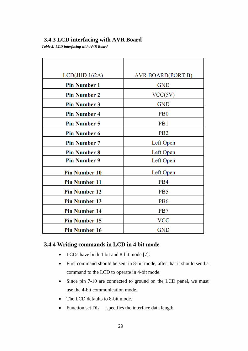
3.4.3 LCD interfacing with AVR Board
3.4.4 Writing commands in LCD in 4 bit mode
LCDs have both 4-bit and 8-bit mode [7].
First command should be sent in 8-bit mode, after that it should send a
command to the LCD to operate in 4-bit mode.
Since pin 7-10 are connected to ground on the LCD panel, we must
use the 4-bit communication mode.
The LCD defaults to 8-bit mode.
Function set DL — specifies the interface data length
Table 5: LCD interfacing with AVR Board

30
- 0-4 bit mode
- 1-8 bit mode
Figure 19: LCD 4 bit interface
31
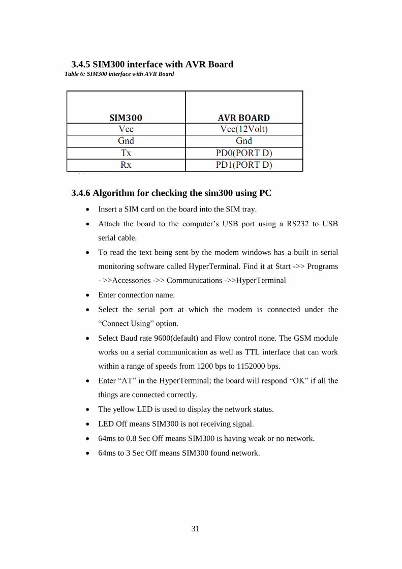
3.4.5 SIM300 interface with AVR Board
3.4.6 Algorithm for checking the sim300 using PC
Insert a SIM card on the board into the SIM tray.
Attach the board to the computer’s USB port using a RS232 to USB
serial cable.
To read the text being sent by the modem windows has a built in serial
monitoring software called HyperTerminal. Find it at Start ->> Programs
- >>Accessories ->> Communications ->>HyperTerminal
Enter connection name.
Select the serial port at which the modem is connected under the
“Connect Using” option.
Select Baud rate 9600(default) and Flow control none. The GSM module
works on a serial communication as well as TTL interface that can work
within a range of speeds from 1200 bps to 1152000 bps.
Enter “AT” in the HyperTerminal; the board will respond “OK” if all the
things are connected correctly.
The yellow LED is used to display the network status.
LED Off means SIM300 is not receiving signal.
64ms to 0.8 Sec Off means SIM300 is having weak or no network.
64ms to 3 Sec Off means SIM300 found network.
Table 6: SIM300 interface with AVR Board
32
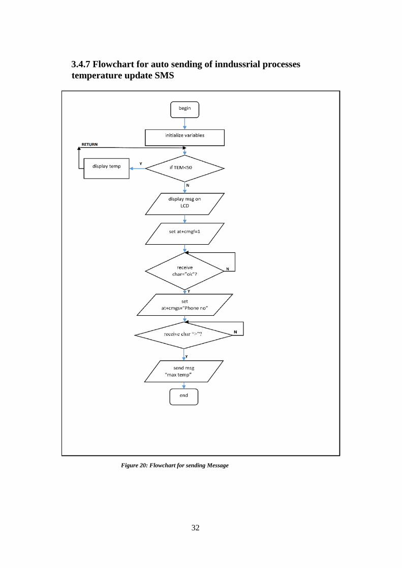
3.4.7 Flowchart for auto sending of inndussrial processes
temperature update SMS
Figure 20: Flowchart for sending Message
33
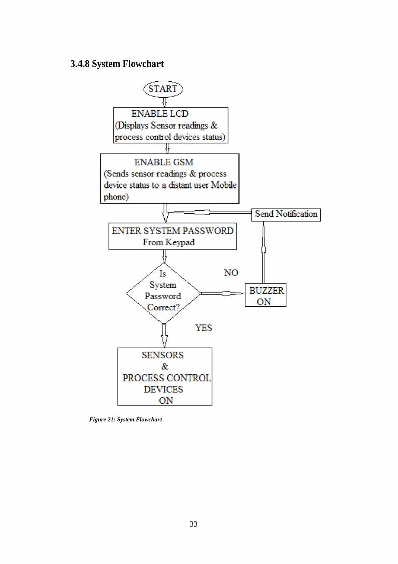
3.4.8 System Flowchart
Figure 21: System Flowchart
34
CHAPTER FOUR
RESULTS AND DISCUSSION
4.0 Introduction
This chapter will describe the results and output of the system design.
4.1 System Evaluation
The following steps were collectively carried out to test; the quality of design,
efficiency and also the reliability of the developed system.
Step 1: System start-up (power-up / boot)
Step 2: Enter the initial authentication system start-up password via the keypad to be
able to switch on industrial system sensors and process control devices.
Step 3: A notification is then displayed on the LCD display upon successful password
input and access control is granted.
Step 4: A wrong initial authentication password entered through the keypad triggers the
buzzer to beep and interrupts the entire system hence no access control is granted.
LM35 senses the temperature of the industrial processes and the data is sent to MCU.
Crystal-oscillator generates frequency of 11.0952MHz used for operation; the data is
stored in EPROM chip which is simultaneously displayed on LCD. Microcontroller
stores the digital data after converting the analog data from sensor unit through ADC,
for some delay unit of time (here 200ms) and resets the reading in MCU as well as in
LCD.
The system is programmed to display data on LCD continuously. Once the temperature
goes above 50 °C, An alert message is displayed “max temp” on LCD. At the same
time it sends a message to the programmed number which reads “max temp reached”
through the GSM Modem. Once the temperature goes below 50°C the MCU displays a
message on LCD which reads “temp now stable” and at the same time it sends
notification to the mobile station saying “temperature now stable”.
35
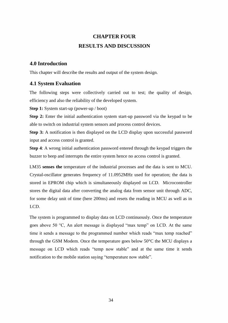
4.2 Results
Below is the list of figures in which LCD displays the output as per changing process
temperature:
1. Condition (temp<50)
The temperature is continuously being displayed till it is below 50 degree.
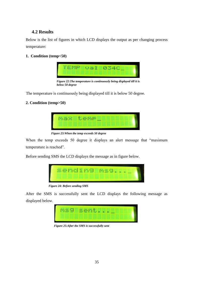
2. Condition (temp>50)
When the temp exceeds 50 degree it displays an alert message that “maximum
temperature is reached”.
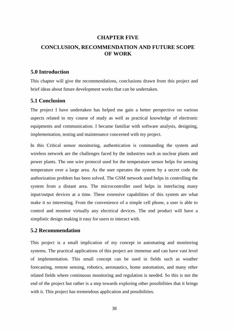
Before sending SMS the LCD displays the message as in figure below.
After the SMS is successfully sent the LCD displays the following message as
displayed below.
Figure 22:The temperature is continuously being displayed till it is
below 50 degree
Figure 23:When the temp exceeds 50 degree
Figure 24: Before sending SMS
Figure 25:After the SMS is successfully sent

36
3. Condition (temp<50)
When the temperature once again falls back below 50°C the following message is
displayed as shown below
Action can be taken to control the industrial process control devices by switching them
ON or OFF depending on the sent sensor data to the GSM phone of the industrial
operator. The following results were obtained.
Table 7: Output results Obtained
S/N
ACTION TAKEN RESULTS
Phone Action
1 pcd1on ProcessControl Device 1 ON
2 pcd1off Process Control Device 1 OFF
3 pcd2on Process Control Device 2 ON
4 pcd2off Process Control Device 2 OFF
Keypad Action
5 1234# System start-up
6 Wrong password# System Interrupt (Buzzer beeps)
4.3 Discussion
GSM Based Industrial Process Monitoring and Control System is a microcontroller
based project and can be implemented practically as displayed. In this project the
temperature sensor (LM 35), and process control devices are connected to ATMEGA32
microcontroller and the temperature readings and device status of the industrial process
control devices are captured and sent to distant Mobile station of the industrial operator
through the GSM modem. These data are simultaneously displayed on LCD. Based
upon the experimentation and implementation, I came to observe that the temperature
Figure 26:When the temperature once again falls back below 50°C

37
sensor data helps the operator to monitor the industrial process control devices and is
able to control the devices based on the data relayed through GSM.
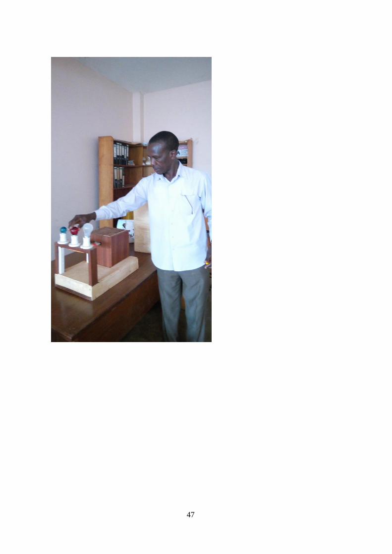
Figure 27: Working model of GSM Based Industrial Process Monitoring and Control System
38
CHAPTER FIVE
CONCLUSION, RECOMMENDATION AND FUTURE SCOPE
OF WORK
5.0 Introduction
This chapter will give the recommendations, conclusions drawn from this project and
brief ideas about future development works that can be undertaken.
5.1 Conclusion
The project I have undertaken has helped me gain a better perspective on various
aspects related to my course of study as well as practical knowledge of electronic
equipments and communication. I became familiar with software analysis, designing,
implementation, testing and maintenance concerned with my project.
In this Critical sensor monitoring, authentication is commanding the system and
wireless network are the challenges faced by the industries such as nuclear plants and
power plants. The one wire protocol used for the temperature sensor helps for sensing
temperature over a large area. As the user operates the system by a secret code the
authorization problem has been solved. The GSM network used helps in controlling the
system from a distant area. The microcontroller used helps in interfacing many
input/output devices at a time. These extensive capabilities of this system are what
make it so interesting. From the convenience of a simple cell phone, a user is able to
control and monitor virtually any electrical devices. The end product will have a
simplistic design making it easy for users to interact with.
5.2 Recommendation
This project is a small implication of my concept in automating and monitoring
systems. The practical applications of this project are immense and can have vast level
of implementation. This small concept can be used in fields such as weather
forecasting, remote sensing, robotics, aeronautics, home automation, and many other
related fields where continuous monitoring and regulation is needed. So this is not the
end of the project but rather is a step towards exploring other possibilities that it brings
with it. This project has tremendous application and possibilities.

39
5.3 Future Scope
The RISC Atmega32 microcontroller can be used for implementation of more complex
systems for complex tasks like controlling different systems like nuclear plants and
reactors in the industry. It can also be used in systems where there is need of
instrumentation, inverting and non-inverting amplifiers.
The project I have undertaken can be used as a reference or as a base for realizing a
scheme to be implemented in other projects of greater level such as weather forecasting,
temperature updates, device synchronization, etc. The project itself can be modified to
achieve a complete Home Automation System which will then create a platform for the
user to interface between himself and his household.
GPRS
General packet Radio service (GPRS) is a packet-based data bearer service for wireless
communication services that is delivered as a network overlay for GSM, CDMA and
TDMA networks. It applies a packet radio principle to transfer user data packet in an
efficient way between GSM mobile station and external packet data networks. Packet
switching is where data is split into packets that are transmitted separately and then
reassembled at the receiving end.
GPRS supports world’s leading packet based internet protocols that makes highly
efficient use of radio spectrum and enables high data speed. It enables any exiting IP or
X.25 application to operate over a GSM cellular connection. Its data speed varies from
115Kbps to 117Kbps but it is likely to average at 56Kbps.
It was developed to enable GSM operators to meet the following key features:
It is a step towards 3G Technology.
Higher bandwidth and therefore data speed.
Seamless, immediate and continues connection to the internet—‘always on-
line’.
New text and visual data content services.
Packet switched rather than circuit switched which enable higher radio spectrum
efficiency.
40
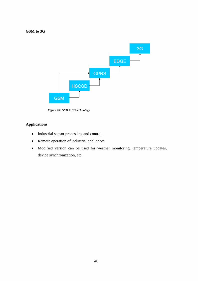
GSM to 3G
Applications
Industrial sensor processing and control.
Remote operation of industrial appliances.
Modified version can be used for weather monitoring, temperature updates,
device synchronization, etc.
Figure 28: GSM to 3G technology
41
REFERENCES
[1] Mohammad Javad Manashti, Houshang Ghamarnia, Soheila Amirian, Ramin
Mohammad Nezhad, "Design GSM-SMS based system for old structured
greenhouses with monitoring and logging network sensors," International
Research Journal of Applied and Basic Sciences, vol. 3, pp. 1497-1507, 2012.
[2] T. Murugan, Azha.Periasamy, S. Muruganand, "Embedded based Industrial
Temperature Monitoring System using GSM," International Journal of
Computer Applications, vol. 58, p. 0975 – 8887, 2012.
[3] Raghu K. Ganti, Fan Ye, and Hui Lei, "Mobile Crowd sensing:Current State
and Future Challenges," IEEE Communications Magazine, 2011.
[4] ATmega32 Datasheet, Atmel Corp., 2006.
[5] LM35 precision centigrade temperature sensors datasheet, National
Semiconductors.
[6] Subhani Sk., Sateesh, Chaitanya and Prakash Babu, "Implementation of GSM
Based Heart Rate and Temperature Monitoring System," Research Journal of
Engineering Sciences, vol. 2, pp. 43-45, April 2013.
[7] "Hitachi HD44780 LCD controller," Hitachi, 1998. [Online]. Available:
en.wikipedia.org/wiki/Hitachi HD44780 LCD controller.
[8] "JHD162A datasheet," [Online]. Available:
www.egochina.net.cn/eBay/Download/JHD162A.pdf.
[9] "SIM300 datasheet," [Online]. Available: probots.co.in/Manuals/SIM300.pdf.
[10] "Liquid-crystal display," Wikipedia, [Online]. Available:
https://en.wikipedia.org/wiki/Liquid-crystal_display.
[11] "Microcontroller to sensor interfacing techniques," BiPOM Electronics INC.,
[Online]. Available: www.bipom.com.
42
[12] Theophilus Wellem, Department of Information Systems, Bhudi Setiawan,
Department of Informatics, Satya Wacana Christian University Salatiga,
Indonesia.,
"A Microcontroller- based Room Temperature Monitoring System,"
International Journal of Computer Applications, vol. 53, no. 1, 2012.
[13] Jifeng Ding, Jiyin Zhao, Biao Ma, College of Electromechanical &
Information
Engineering, Dalian Nationalities University Dalian, China, "Remote
monitoring
system of temperature and humidity based on GSM," in 2nd International
Congress on Image and Signal Processing, 2009.

43
APPENDIX
Appendix A: Project Time-Frame
Table 8: Project Time-Frame
SN ACTIVITY/TASK PERIOD
2019
JAN FEB MAR APR
1. Title identification
2. Problem statement identification
3. Proposal writing
4. Proposal presentation and
Gathering requirements
5. System design
6. Testing and validation
7. Report draft and approval, and
Project presentation
8. Final report submission
44
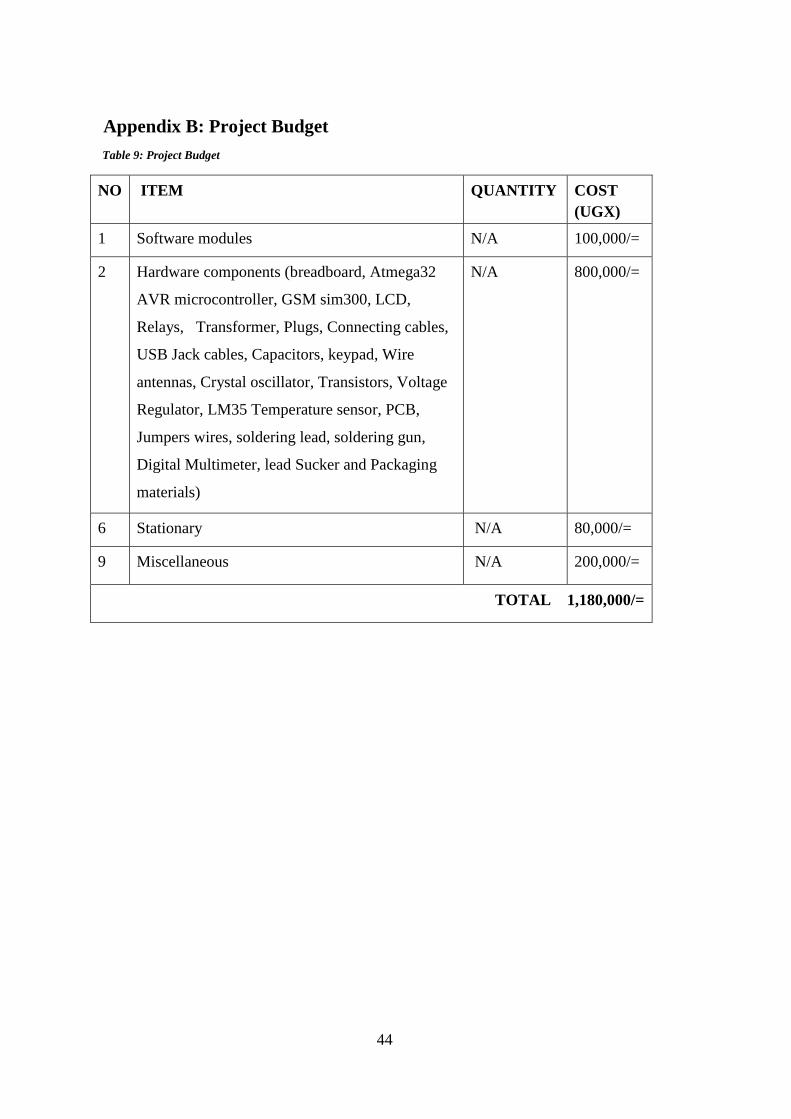
Appendix B: Project Budget
Table 9: Project Budget
NO ITEM QUANTITY COST
(UGX)
1 Software modules N/A 100,000/=
2 Hardware components (breadboard, Atmega32
AVR microcontroller, GSM sim300, LCD,
Relays, Transformer, Plugs, Connecting cables,
USB Jack cables, Capacitors, keypad, Wire
antennas, Crystal oscillator, Transistors, Voltage
Regulator, LM35 Temperature sensor, PCB,
Jumpers wires, soldering lead, soldering gun,
Digital Multimeter, lead Sucker and Packaging
materials)
N/A 800,000/=
6 Stationary N/A 80,000/=
9 Miscellaneous N/A 200,000/=
TOTAL 1,180,000/=

45

46
47