design and fabrication of bio-inspired …
TRANSCRIPT

The Pennsylvania State University
The Graduate School
Department of Mechanical and Nuclear Engineering
DESIGN AND FABRICATION OF BIO-INSPIRED MULTIFUNCTIONAL SLIPPERY
SURFACE COATINGS WITH NOVEL FUNCTIONALITIES
A Dissertation in
Mechanical Engineering
by
Jing Wang
2018 Jing Wang
Submitted in Partial Fulfillment
of the Requirements
for the Degree of
Doctor of Philosophy
August 2018
The dissertation of Jing Wang was reviewed and approved* by the following:
Tak Sing Wong
Assistant Professor of Mechanical Engineering and Bioengineering
Dissertation Advisor
Chair of Committee
Pak Kin Wong
Professor of Bioengineering and Mechanical Engineering
Donghai Wang
Associate Professor of Mechanical Engineering
Seong Kim
Professor of Chemical Engineering
Karen Thole
Distinguished Professor
Head of the Department of Mechanical and Nuclear Engineering
*Signatures are on file in the Graduate School

iii
ABSTRACT
Bio-inspired multi-functional liquid-repellent surfaces have been intensively studied for
the past decades because of their significant potentials for many industrial and biomedical
applications. To this end, state-of-the-art surfaces including superhydrophobic surfaces,
superoleophobic surfaces, and slippery liquid-infused porous surfaces (SLIPS) have been
developed, where these surfaces display a number of remarkable functions such as self-cleaning,
anti-biofouling, anti-icing, drag reduction, enhanced heat transfer and water harvesting. Despite
recent advances, surfaces that possess self-cleaning and anti-fouling properties while at the same
time are capable of repelling both liquids and viscoelastic solids or with enhanced mechanical
robustness are rare. A central feature of this dissertation is to develop design principles to create
such a multi-functional repellent coating, and develop a facile and scalable fabrication method to
apply the coating onto common materials such as glass, ceramics, metals, and plastics. Here, I
have developed a new form of cross-species bio-inspired slippery liquid-infused porous surfaces
(X-SLIPS) that can self-repair under thermal stimulation even under large area of physical and
chemical damages. These thermally self-healing omniphobic coatings can be applied onto a broad
range of metals, plastics, glass, and ceramics of various shapes, and show excellent repellency
towards aqueous and organic liquids. In addition, I have designed and fabricated liquid-
entrenched smooth surfaces (LESS) – a sprayable, anti-biofouling surface coating that is capable
of repelling both aqueous liquids and viscoelastic solids with dynamic viscosities spanning over 9
orders of magnitude, i.e., three orders of magnitude higher than previously reported. LESS can
significantly reduce adhesion from different viscoelastic solids up to ~90% compared to state-of-
the-art liquid-repellent materials. The amount of water required to clean LESS is only ~10% of
that required for untreated surfaces. The results have implications for significant reduction of
wastewater generation and biofouling in industrial and household settings, which may mitigate

iv
global water scarcity and transmission of the infectious diseases, associated with poor sanitation
facilities.

v
TABLE OF CONTENTS
LIST OF FIGURES ................................................................................................................. vii
LIST OF TABLES ................................................................................................................... xii
ACKNOWLEDGEMENTS ..................................................................................................... xiii
Chapter 1 Introduction ............................................................................................................. 1
1.1 A Brief Overview of Bio-inspired Liquid Repellent Surfaces ................................... 1
1.2 State-of-the-art Liquid Repellent Surfaces ................................................................. 4
1.2.1 Superhydrophobic and Superoleophobic Surfaces .......................................... 4
1.2.2 Slippery Liquid-infused Porous Surfaces ........................................................ 10
1.2.3 Limitations of the State-of-the-art Liquid Repellent Surfaces ........................ 15
1.3 Objectives of the Dissertation .................................................................................... 16
Chapter 2 Slippery Liquid-infused Porous Surfaces with Self-healing Property..................... 17
2.1 Motivation of the Study ............................................................................................. 17
2.2 Fabrication of Cross Species Bioinspired Slippery Liquid-Infused Porous
Surfaces (X-SLIPS) .................................................................................................. 19
2.3 Characterization of Self-Healing Mechanism ............................................................ 20
2.4 Robustness Characterization ...................................................................................... 25
2.5 Chapter Summary ...................................................................................................... 29
Chapter 3 Viscoelastic solid repellent surfaces ........................................................................ 30
3.1 Motivation of the Study ............................................................................................. 30
3.2 Design of Viscoelastic Solid Repellent Surfaces ....................................................... 33
3.2.1 Design Criteria I: Interfacial Adhesion ........................................................... 33
3.2.2 Design Criteria II: Interfacial Wetting ............................................................ 37
3.3 Fabrication of Liquid-Entrenched Smooth Surfaces (LESS) ..................................... 41
3.4 Adhesion of LESS against Viscoelastic Feces ........................................................... 42
3.5 Water Consumption of LESS ..................................................................................... 45
3.5.1 Simulated Toilet Flushing ............................................................................... 45
3.5.2 Water Consumption of Various Surfaces ........................................................ 47
3.6 Adhesion against Human Feces ................................................................................. 48
3.7 Anti-Bacterial Performance of LESS ......................................................................... 50
3.8 Durability of LESS ..................................................................................................... 55
3.9 Chapter Summary ...................................................................................................... 58
Chapter 4 Summary and Discussion ........................................................................................ 60
Appendix A Experiments on Fabrication and Characterization of X-SLIPS.......................... 62
Appendix B Calculation of Work of Adhesion ....................................................................... 65

vi
Appendix C Identification of Bacteria in Rainwater .............................................................. 66
References ................................................................................................................................ 67
vii
LIST OF FIGURES
Figure 1-1: A brief history of bio-inspired liquid-repellent surfaces. ...................................... 2
Figure 1-2: Other examples of bio-inspired liquid-repellent surfaces. The scanning
electron microscope (SEM) images for butterfly wing, mosquito eyes, and
leafhopper brochosomes are obtained from references [10], [11], and [12],
respectively. ..................................................................................................................... 3
Figure 1-3: State-of-the-art designs for superhydrophobic or superoleophobic surfaces,
including surface structure, structure orientation, structure size, and surface
chemistry. ......................................................................................................................... 5
Figure 1-4: Illustration of re-entrant and double re-entrant structures of superoleophobic
surfaces............................................................................................................................. 6
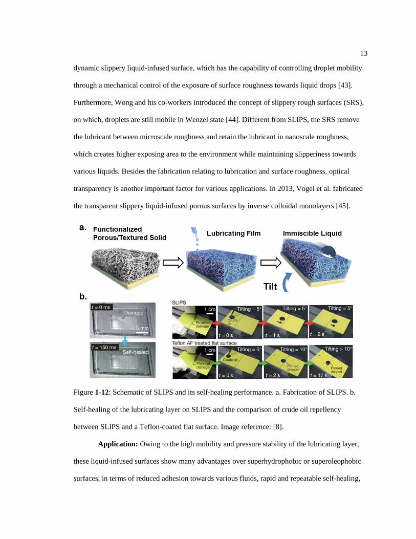
Figure 1-5: Cacida-inspired jumping droplet superhydrophobic surfaces for enhance heat
transfer. Image credit: Reference [18]. ............................................................................ 6
Figure 1-6: Chemical structures of PTFE, PDMS, and POSS. ................................................ 7
Figure 1-7: Re-entrant and double re-entrant surface structures created by silicon etching.
SEM images credit: Reference [5] and [7]. ...................................................................... 8
Figure 1-8: Superhydrophobic or superoleophobic surfaces created by micro/nano beads
self-assembly. a. Schematic showing how the self-assembled structure can repel
liquids. b. SEM image of self-assembled candle soot. c. SEM image of self-
assembled TiO2 beads. Image credit: reference [25] and [27]. ........................................ 9
Figure 1-9: Application examples of superhydrophobic surfaces. a. An illustration of drag
reduction. b. A demonstration of anti-icing performance on superhydrophobic
surfaces. c. Nano-cone shape superhydrophobic surface used for anti-fogging. d. A
patterned superhydrophilic/superhydrophobic surface for fog harvesting. Image
credit: Reference [15], [35], and [32]. .............................................................................. 10
Figure 1-10: Overview of state-of-the-art development of SLIPS. .......................................... 11
Figure 1-11: Schematic drawings illustrating the interfacial energy at different wetting
status. Image credit: Reference [8]. .................................................................................. 12
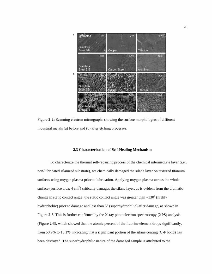
Figure 1-12: Schematic of SLIPS and its self-healing performance. a. Fabrication of
SLIPS. b. Self-healing of the lubricating layer on SLIPS and the comparison of
crude oil repellency between SLIPS and a Teflon-coated flat surface. ............................ 13
Figure 1-13: Application examples of slippery liquid-infused porous surfaces (SLIPS). a.
The anti-icing and frosting comparison of uncoated surfaces and SLIPS. b. Anti-
bacteria fouling comparison of superhydrophobic surfaces and SLIPS. c. Anti-
marine fouling performance of liquid-infused PDMS. d. Blood repellency of SLIPS-
viii
coated glass. e. An ultra-sensitive SERS detection SLIPS platform. Image credit:
References [45], [54], [48], [47], and [53], respectively. ................................................. 14
Figure 2-1: Cross-species bio-inspired slippery coating: X-SLIPS. a. Optical images
showing a plant leaf and a Nepenthes pitcher plant. b. Schematic showing the
concept of slippery coating fabrication process inspired by the slippery rim of the
Nepenthes pitcher plant. c. Schematic showing the concept of self-repairing inspired
by the wax repair of plant leaves. The excess silane layer (hydrophobic wax) on a
substrate serves a reservoir to repair the surface hydrophobicity, and to prevent the
lubricant from being displaced by the foreign liquids. Insets showing the liquid
repellency comparison of octane droplets on lubricated substrates with undamaged
(left) and damaged (right) silane coating. ........................................................................ 18
Figure 2-2: Scanning electron micrographs showing the surface morphologies of different
industrial metals (a) before and (b) after etching processes. ............................................ 20
Figure 2-3: Mechanism of thermal self-repairing. a. The contact angle change before and
after oxygen plasma damage, as well as after the thermal self-repairing. b. XPS data
of silanized surface before and after oxygen plasma, as well as after thermal
treatment. The substrate is titanium, and the silane is perfluorinated silane. The
atomic percent of fluorine and titanium at each condition is shown in the inset chart
and is the average of three different measuring areas. c. Schematics of self-repairing
mechanism, which involves the vaporization of the silane molecules. ............................ 22
Figure 2-4: Robustness and thermal self-healing performance on the chemical
intermediate layer of X-SLIPS. a. Optical images showing the water repellency
comparison between a damaged and a self-healed chemical intermediate layer on
titanium. b. A plot showing the thermal self-healing repeatability of the intermediate
layer of X-SLIPS. A 20 µL octane droplet was used for measuring the sliding angle
on a tilting stage. The intact or self-healing surface with lubricant has a very small
sliding angle of around 10o; while the surface after damage has a 90
o sliding angle. c.
A plot showing the dependence of thermal-healing time on applied temperature.
Damaged intermediate layer can be healed around 280 min at 60 ℃, while less 1
min at more than 180 ℃. The semi-log plot shows that the self-healing rate and the
heating temperature fits the Arrhenius relationship. In the inset, t is the thermal
healing time in second, and T is heating temperature in Kelvin. The sample for this
experiment is silanized titanium. Error bars indicate standard deviations for three
independent measurements. ............................................................................................. 23
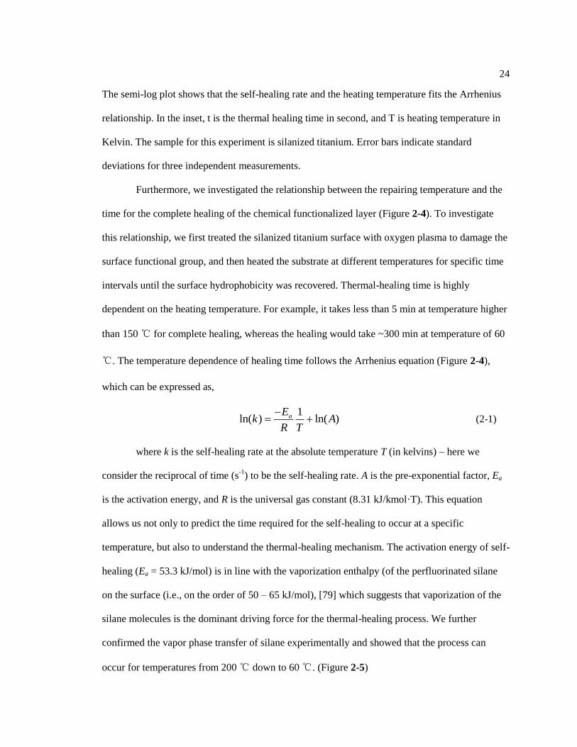
Figure 2-5: Demonstration of silane evaporation upon substrate heating. a. Silicon wafer
1 is etched with microstructures and is highly hydrophilic. b. Silicon wafer 2 is a
silanized surface with etched microstructures and is highly hydrophobic. c, d.
Schematic showing the experimental setup. Note that wafer 2 was in contact with
the hot plate and was heated at a temperature of at 60 oC for >3 hours or 200
oC for
10 min. e. After the heating process, the wafer 1 was observed to become
hydrophobic, confirming that part of the silane molecules were transferred from
wafer 2 to wafer 1. ........................................................................................................... 25

ix
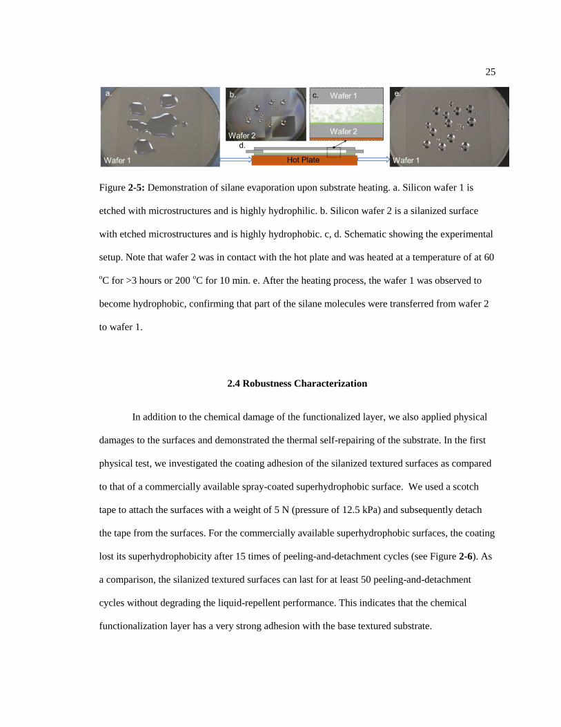
Figure 2-6: Coating adhesion test for the silanized textured surface and a commercial
surperhydrophobic coating. a. Performance comparison of the coating adhesion
between the silanized textured surface and the superhydrophobic coating. The
adhesion test protocol includes the use of a scotch tape to adhere onto the testing
surface with a 5 N weight on top of it. The tape was then peeled off from the
surface. After each peeling test, we measured the sliding angle of a 20 μL droplet of
deionized water. Low sliding angle indicated that the surface is slippery. b. Real
time images showing water repellency performance on the two surfaces after the
scotch tape peeling test. After 20 times of peeling, the commercial superhydrophobic
coating completely lost its superhydrophobicity; while our silane coating still
maintained its liquid repellency. Water is colored with blue dye for visual
representation. .................................................................................................................. 26
Figure 2-7: Self-repair of X-SLIPS coating. a. A plot showing the physical abrasion
performance comparison between lubricated and non-lubricated samples. Each
abrasion cycle involved dragging a sandpaper of average particle size of 470 µm
along with a pressure of 15.6 kPa across the surface with a velocity of ~0.02 m/s. b.
Optical images showing the thermal repair of X-SLIPS on glass, polyethylene, and
ceramic. The coating was damaged by physical abrasion of sandpaper. ......................... 28
Figure 2-8: Liquid repellency of X-SLIPS coating on various materials. a. A plot showing
the contact angle hysteresis of various liquids on the slippery surfaces. Inset shows a
dodecane droplet sliding with a very small sliding angle (less than 3°) on a coated
carbon steel substrate, indicating the super slippery nature of the surfaces. Error bars
represent the standard deviations for at least four independent measurements. b. The
coating method can be applied to various substrates such as stainless steel,
aluminum, titanium, glass, copper, carbon steel, ceramic, and polyethylene. The
yellow droplet is 10 μL dyed octane. c. Comparison of untreated and X-SLIPS-
coated stainless steels of different surface geometries (flat plate, pipe section, and
sphere) for the repellency of dyed octane (in yellow). ..................................................... 28
Figure 3-1: Overview of state-of-the-art liquid and viscoelastic solid repellent surfaces.
(A) Schematic and optical images showing the comparison of adhesion between
viscoelastic solids and different engineered surfaces including a superhydrophobic
glass (left), a SLIPS-coated glass (center), and a LESS-coated glass (right). The
superhydrophobic glass was created using a commercially available
superhydrophobic coating (NeverWet, LLC). The SLIPS-coated glass has an
underlying surface roughness ~1 µm. Synthetic feces with a solid content percentage
of 30% (dynamic viscosity = ~2406 Pa·s) were used in these experiments. (B) A plot
showing the reported dynamic viscosity range of liquids and viscoelastic solids that
can be repelled by the state-of-the-art liquid repellent surfaces and the present work. ... 31
Figure 3-2: Schematics showing adhesion of viscoelastic solids on surfaces with different
surface treatments. Adhesion of viscoelastic solids on a) an untreated surface; b) a
silanized surface; c) a lubricated surface without chemical treatment; and d)
lubricated surface with silanization treatment. ................................................................. 34

x
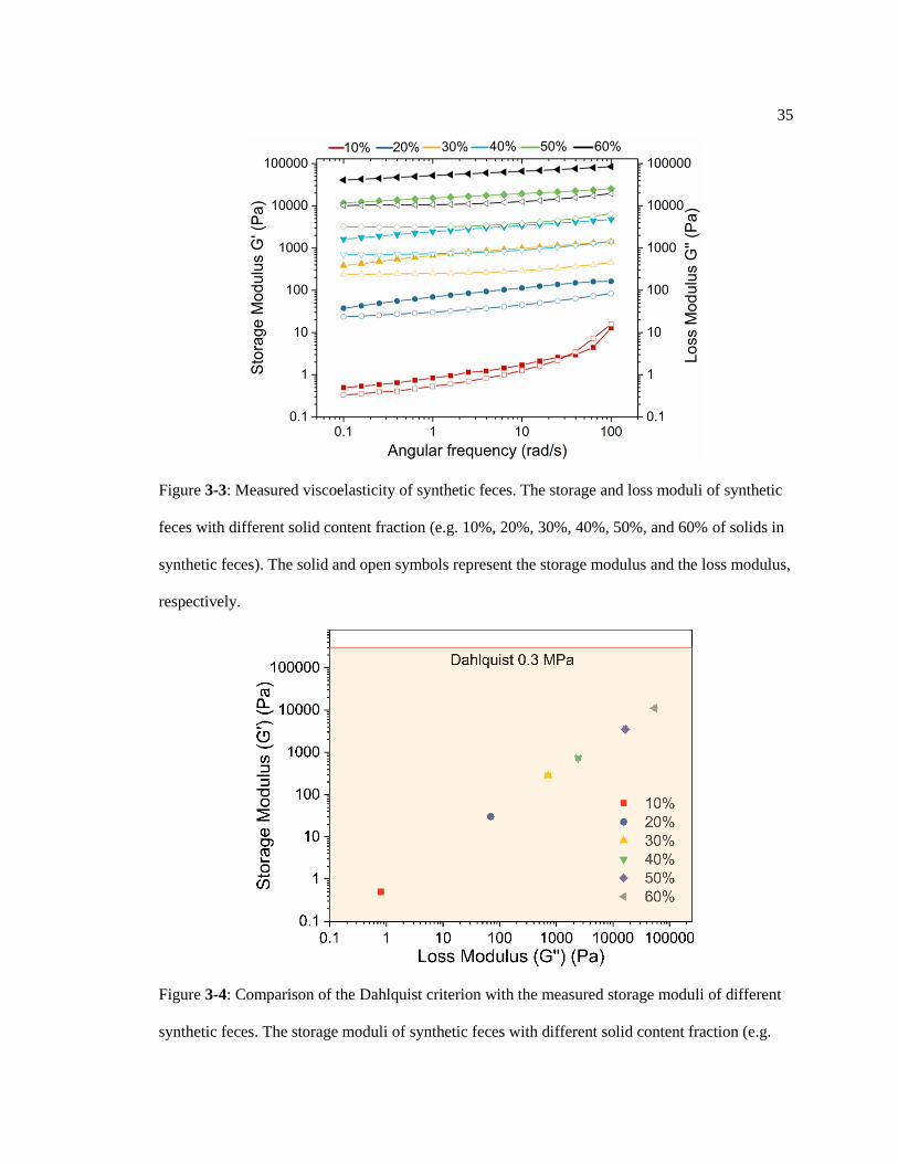
Figure 3-3: Measured viscoelasticity of synthetic feces. The storage and loss moduli of
synthetic feces with different solid content fraction (e.g. 10%, 20%, 30%, 40%,
50%, and 60% of solids in synthetic feces). The solid and open symbols represent
the storage modulus and the loss modulus, respectively. ................................................. 35
Figure 3-4: Comparison of the Dahlquist criterion with the measured storage moduli of
different synthetic feces. The storage moduli of synthetic feces with different solid
content fraction (e.g. 10%, 20%, 30%, 40%, 50%, and 60% of solid in synthetic
feces) under frequency of 1 rad/s. The error bars represent standard deviations of
storage moduli from three independent measurements. ................................................... 35
Figure 3-5: Fabrication of liquid-entrenched smooth surfaces (LESS). (A) Schematic
illustration showing a two-step spray coating process to form LESS. (B) Optical
images showing the individual coating processes on glass. The lubricant used was
silicone oil and the blue testing liquid was dyed water. ................................................... 41
Figure 3-6: XPS characterizations of silicon element on untreated (e.g. glass) and PDMS-
grafted substrates. a, The peak of silicon element is originated from silicon dioxide,
which is the main component of glass. b, The peak of silicon element (Si 2p) is
originated from silicon dioxide and silicone, which confirmed the presence of the
PDMS on the PDMS-grafted substrate. ........................................................................... 42
Figure 3-7: Adhesion comparison among different surfaces. .................................................. 43
Figure 3-8: Adhesion comparison among surfaces with different roughness. ......................... 44
Figure 3-9: Surface roughness measurement on different surfaces. ........................................ 45
Figure 3-10: Water consumption on different surfaces under different flow rate with
impact of different feces................................................................................................... 48
Figure 3-11: Experimental setup of simulated flushing. .......................................................... 48
Figure 3-12: Comparison of adhesion on different surfaces with impact of human fecal
waste. ............................................................................................................................... 49
Figure 3-13: Adhesion on SLIPS with impact of human fecal waste. ..................................... 50
Figure 3-14: Rainwater bacteria concentration measurement. ................................................. 51
Figure 3-15: Bacteria adhesion measurement on different surfaces. ....................................... 52
Figure 3-16: Sliding angle of urine on different surfaces. ....................................................... 53
Figure 3-17: Sterilization of liquid-infused surfaces with different underlying roughness. .... 54
Figure 3-18: Rainwater bacteria identification. ....................................................................... 54
Figure 3-19: Durability measurement on LESS with contamination of different feces. .......... 55

xi
Figure 3-20: Durability and replenishment of the lubricant layer on LESS. ........................... 57
xii
LIST OF TABLES
Table 3-1: Compositions of the synthetic feces. ...................................................................... 37
Table 3-2: Surface energy components for materials at ambient environment. ....................... 40
Table 3-3: Calculated spreading parameters (S) and Hamaker constant (A) for liquids on
PDMS-grafted glass. ........................................................................................................ 40
Table 3-4: Physical parameters for the simulated-toilet flushing systems. .............................. 47
Table 3-5: Bacteria identification from mass spectrometry. .................................................... 51

xiii
ACKNOWLEDGEMENTS
I would like to thank my adviser Professor Tak Sing Wong for his guidance and
encouragement over the course of this research. His leadership has not only enabled me to
develop as a graduate student but also instilled in me a sense of passion for the work one is
committed to. I would also like to thank my committee Professor Pak Kin Wong and Dr. Leon
Williams of Crafield University, UK, for their input in this research.
As the first PhD student in Prof. Wong’s group, I am extremely fortunate to experience
the establishment and development of the laboratory and the research team. I am grateful that
Prof. Wong has brought so many talented researchers and friendly colleagues in the group. I
would like to thank former postdoctoral researchers in the group, specifically, Dr. Shikuan Yang
for sharing his research experience and encouraging me to continue my research journey, Dr.
Xianming Dai and Dr. Yu Huang for involving me in their research projects. I would also like to
thank my colleagues, Nan Sun, Birgitt Boschitsch, Ryan Sikorski, Lin Wang, Antonino
Turrigiano, for the help in experiments and many fruitful discussions.
I would like to gratefully acknowledge the support of the National Science Foundation
(Grant Nos. 1351462 and 1757165) and PPG Foundation for funding this research. I would like to
thank the Materials Research Institute, Pennsylvania State University for using of their facilities
for micro/nano fabrication and material characterization. Specifically, I would like to thank Vince
Bojan for his help on XPS measurement, Dr. Bangzhi Liu for his help on SEM imaging, Michael
Labella and Chad Eichfeld for their help on photolithography, Tim Tighe for his help on AFM
and optical profilometer, Josh Stapleton for his help on optical measurements, and Maria Dicola
for her help and supervise on the laboratory safety.

xiv
I am forever indebted to my parents Zhuangzhi Wang and Liping Ma for their selfless
love, support, and encouragement throughout my life. They are the ones who are wholly and
solely behind all that I am. Finally, I would like to thank my beloved wife Yiyu Xu and lovely
daughter Skylar Wang, without whom I cannot achieve this work.

Chapter 1
Introduction
1.1 A Brief Overview of Bio-inspired Liquid Repellent Surfaces
Liquid repellency is a crucial property for various living species in nature, ranging from
plants to insects to animals. Researchers have been inspired by these species to design and
fabricate various liquid repellent surfaces for industrial, biomedical, agricultural, and daily-life
applications. In 1944 (Figure 1-1) [1], Cassie and Baxter studied how ducks use their feathers to
stay dry when contacting water, and developed the well-known Cassie-Baxter equation, which
predicts the influence of surface structure and chemistry on liquid repellency. This equation
becomes one of the most important fundamental governing equations in surface wetting science.
The Cassie-Baxter equation is also a powerful tool to guide the surface structure design for
superhydrophobic surfaces. With the first synthesis of polytetrafluoroethylene (PTFE) in 1938,
which is also known as Teflon, researchers have been trying to create man-made
superhydrophobic surfaces since then. The first reported synthetic superhydrophobic surface was
developed using roughened PTFE in 1991 [2]. In the late 1990s, Barthlott and Neinhuis [3] first
revealed the mechanism of the superhydrophobicity on lotus leaf by studying the surface structure
using high resolution scanning electron microscope (SEM). Lotus leaf can repel water and self-
clean because of the trapped air within its hierarchical micro and nano surface structures. The
contact angle of a water drop on a lotus leaf is generally around 170o. Since then, people have
discovered that many plant leaves also exhibit superhydrophobicity with a water contact angle of
around 160o.

2
Figure 1-1: A brief history of bio-inspired liquid-repellent surfaces.
In the 21st century, superhydrophobic surfaces have been developed rapidly for various
applications. Specifically, the high demand of oil-repellent surfaces has greatly accelerated the
progress of the field. Though oil-repellent surfaces have been created with porous PTFE fibers
[4], the underlying mechanism had not been understood until the creation of re-entrant surfaces in
2007 [5]. The re-entrant surface structure, also known as hoodoo structure, has been focused in
the past decade for creating scalable and durable superoleophobic surfaces. Four years later after
the discovery of re-entrant surfaces, people found out that natural species also use this special
surface structure to keep their body clean from muddy environment [6]. These nature species are
springtails. Springtails live in a harsher environment than plant leave, and thereby require better
liquid-repellency. To adapt to the muddy underground environment, springtails have evolved
these re-entrant or even double re-entrant surfaces in different body parts. Inspired by these
underground hexapods, the double re-entrant surfaces were first fabricated in 2014 [7]. Different
from hierarchical and re-entrant structure, which requires low surface energy chemical coatings,
the double re-entrant structure does not require surface chemistry modification to achieve
superoleophobicity.

3
Both superhydrophobic and superoleophobic surfaces use surface structures to trap a thin
layer of air in order to create a minimal contact of water towards solid surfaces. In this case,
liquid drops typically maintain a near spherical shape due to capillarity and roll off these surfaces
easily. In 2011, another type of liquid-repellent surfaces was developed by infusing lubricants
into porous surfaces [8]. Through the lubrication, surfaces can achieve repellency towards
immiscible foreign liquids. This liquid-infusing strategy was inspired by the Nepenthes pitcher
plant, whose rim gets wetted in moisture and becomes super slippery. Insects, such as ants, use
viscous oils on their feet to walk on smooth surfaces [9]. Owing to the immiscibility of the
adhesive oil and the water film on rim surfaces, ants will slide off from rim of pitcher plant due to
hydroplaning. Bohn and Federle discovered this passive pray strategy on pitcher plant in 2004
[10], which inspired material scientists to create the slippery liquid-infused porous surfaces
(SLIPS) and open up a new research direction in liquid-repellent surface design.
Figure 1-2: Other examples of bio-inspired liquid-repellent surfaces. The scanning electron
microscope (SEM) images for butterfly wing, mosquito eyes, and leafhopper brochosomes are
obtained from references [11], [12], and [13], respectively.

4
With over ~8.7 million eukaryotic species predicted globally [14], there are many more
biological examples that could inspire us for designing liquid-repellent surfaces with special
functions. In Figure 1-2, I have listed a few well-known species that have been studied in recent
years. For example, the butterfly wing surfaces have anisotropic micro/nano structures, which
makes water droplets roll in the direction away from butterfly body [15]. These structures inspire
research of directional superhydrophobic surfaces and directional slippery rough surfaces for drop
transportation and condensation applications, respectively. Additionally, the mosquito eyes have
been proven to repel micro droplets, showing significant anti-fogging performance [12]. A recent
research has revealed that the nanoscale pillars play an important role of anti-fogging [16], which
is significant for astronauts’ face shields [17]. In another example, the leafhopper brochosomes
demonstrate strong water repellency [18] as well as ultra-anti-reflective property. Researchers
have successfully manufactured the artificial brochosomes recently and demonstrated their strong
anti-reflection property [13]. These nano porous micro balls could be utilized as a surface coating
to enhance solar energy absorption. In summary, nature has been inspiring us to create novel
surface designs for a variety of applications, especially for liquid repellent coatings.
1.2 State-of-the-art Liquid Repellent Surfaces
1.2.1 Superhydrophobic and Superoleophobic Surfaces
Superhydrophobic and superoleophobic surfaces have been intensively studied in three
major areas: design, fabrication, and applications. In this section, I will briefly introduce the state-
of-the-art superhydro(oleo)phobic surfaces in each of these areas.

5
Figure 1-3: State-of-the-art designs for superhydrophobic or superoleophobic surfaces, including
surface structure, structure orientation, structure size, and surface chemistry.
Design: To design a superhydrophobic or superoleophobic surfaces, researchers have
focused on different design parameters, including surface structure, structure size, structure
orientation, and low surface energy chemicals, (Figure 1-3). Since the discovery of the
micro/nano hierarchical structure on lotus leaf, various surface structures have been designed
based on fundamental thermodynamic principles or by direct mimicking of specific natural
species. Among various surface structure designs, the re-entrant and double re-entrant surface
structures are the most significant designs for robust superhydrophobic surfaces. The re-entrant
structure enables robust superhydrophobicity on hydrophobic materials; while the double re-
entrant structure extends the robustness liquid repellency to hydrophilic materials (Figure 1-4). In
addition to re-entrant and double re-entrant structures, many other surface structures have been
designed to address different application requirements, for example, cone-shape structure (Figure
1-5) has been designed to induce jumping droplet effect for enhanced heat transfer in
condensation [19]. This surface structure was inspired by the surface of cicada wing, which can
stay dry in high moisture environment. Furthermore, by tuning the size of the cone-shape
structure, researchers have achieved a number of significant improvements on superhydrophobic
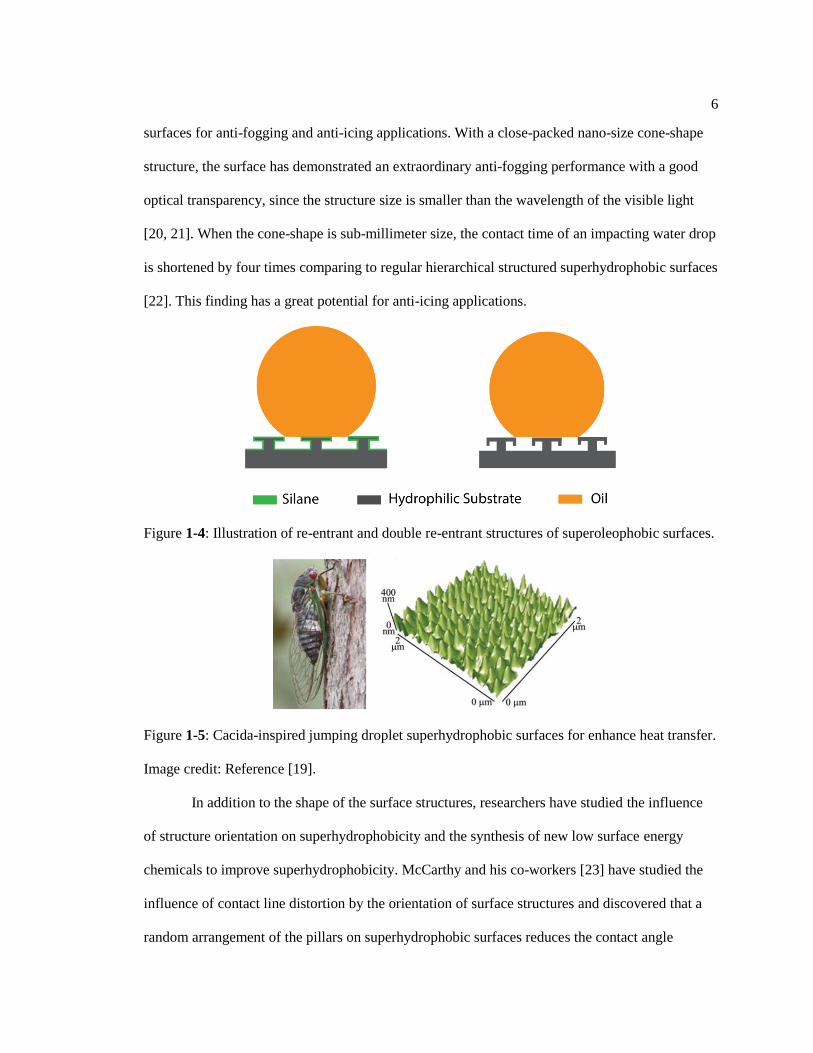
6
surfaces for anti-fogging and anti-icing applications. With a close-packed nano-size cone-shape
structure, the surface has demonstrated an extraordinary anti-fogging performance with a good
optical transparency, since the structure size is smaller than the wavelength of the visible light
[20, 21]. When the cone-shape is sub-millimeter size, the contact time of an impacting water drop
is shortened by four times comparing to regular hierarchical structured superhydrophobic surfaces
[22]. This finding has a great potential for anti-icing applications.
Figure 1-4: Illustration of re-entrant and double re-entrant structures of superoleophobic surfaces.
Figure 1-5: Cacida-inspired jumping droplet superhydrophobic surfaces for enhance heat transfer.
Image credit: Reference [19].
In addition to the shape of the surface structures, researchers have studied the influence
of structure orientation on superhydrophobicity and the synthesis of new low surface energy
chemicals to improve superhydrophobicity. McCarthy and his co-workers [23] have studied the
influence of contact line distortion by the orientation of surface structures and discovered that a
random arrangement of the pillars on superhydrophobic surfaces reduces the contact angle

7
hysteresis of a liquid droplet. Since the synthesis of PTFE and PDMS around 1940, researchers
have synthesized numerous silanes and siloxanes as low surface energy chemicals to create
superhydrophobic surfaces. One of the well-known chemicals developed in recent years is the
polyhedral oligomeric silsesquioxane (POSS) (Figure 1-6) [5], which has been successfully used
to fabricate robust superoleophobic surfaces.
Figure 1-6: Chemical structures of PTFE, PDMS, and POSS.
Fabrication: To fabricate superhydrophobic or superoleophobic surfaces, many
manufacture methods have been developed, with a particular focus on fabrication scalability and
the coating robustness. One early conventional method to create superhydrophobic surfaces is to
deposit low surface energy chemicals (e.g. PTFE) on rough or porous surfaces [2]. With a better
understanding of superhydrophobic surface design, various methods have been developed, such
as direct replication of natural surfaces [24], silicon etching [25], self-assembly of micro and nano
beads [26], block copolymer formation [27], etc. For example, the re-entrant and double re-
entrant structures are examples of super/oleohydrophobic surfaces fabricated using silicon etching
method (Figure 1-7). However, the key drawback of direct replication and silicon etching
methods is that they are scalable and for silicon etching, the process is relatively expensive.

8
Figure 1-7: Re-entrant and double re-entrant surface structures created by silicon etching. SEM
images credit: Reference [5] and [7].
To realize scalable superhydrophobic surfaces, several methods have been developed in
past decades. One of the most widely adapted methods is the self-assembly of micro and nano
beads (e.g. SiO2 and TiO2) (Figure 1-8) [26, 28]. Micro and nano beads with a certain ratio are
suspended in a silane solution. With the help of super glue, this mixture is sprayed onto the glue
layer, and strongly adheres onto the surface. Hierarchical or even re-entrant surface structures can
be created by this method. In a recent study, an organic superhydrophobic coating was created by
using PTFE beads [29]. Although the robustness of these superhydrophobic surfaces are stronger
than silicon-based superhydrophobic surfaces, these surfaces still cannot withstand extremely
harsh working environments, such as strong mechanical abrasion, high hydrostatic pressure,
marine biofouling, etc.

9
Figure 1-8: Superhydrophobic or superoleophobic surfaces created by micro/nano beads self-
assembly. a. Schematic showing how the self-assembled structure can repel liquids. b. SEM
image of self-assembled candle soot. c. SEM image of self-assembled TiO2 beads. Image credit:
reference [26] and [28].
Applications: Superhydrophobic surfaces have shown a number of potential applications
(Figure 1-10), such as drag reduction [30, 31], enhanced heat transfer [32], fog harvesting [33],
anti-fogging [16, 34], anti-icing [35, 36], etc. All these applications are enabled by the thin air
layer created by the surface structure and chemistry of the superhydrophobic surfaces. A number
of superhydrophobic surfaces are currently being commercialized, e.g., NeverWet®. Although
there are many potential applications of the superhydrophobic or superoleophobic surfaces,
pressure stability, scalable fabrication, and coating robustness are still major issues that need to be
solved.

10
Figure 1-9: Application examples of superhydrophobic surfaces. a. An illustration of drag
reduction. b. A demonstration of anti-icing performance on superhydrophobic surfaces. c. Nano-
cone shape superhydrophobic surface used for anti-fogging. d. A patterned
superhydrophilic/superhydrophobic surface for fog harvesting. Image credit: Reference [16], [36],
and [33].
1.2.2 Slippery Liquid-infused Porous Surfaces
To address the poor pressure stability in superhydrophobic or superoleophobic surfaces,
another type of liquid repellent surface was developed by changing the air-cushion into a liquid
lubricating layer, which makes the foreign immiscible liquid drops float on this lubricant layer.
This surface was first developed by infusing lubricant into a porous surface in 2011 [8] and
showed strong omniphobicity and great potential for various applications. The surface was

11
referred to as slippery liquid-infused porous surfaces (SLIPS). After the development of SLIPS,
many slippery liquid-infused surfaces have been designed, fabricated, and applied to numerous
applications, shown in Figure 1-10. I will briefly introduce some of the state-of-the-art
development of SLIPS in design, fabrication, and application.
Figure 1-10: Overview of state-of-the-art development of SLIPS.
Design: Currently, the design of slippery liquid-infused porous surfaces (SLIPS) is
primarily based on thermodynamic analysis. From the initial design of SLIPS, Wong and his co-
workers compared the surface energy of different wetting status (Figure 1-11), including liquid A
on substrate (EA), liquid B on substrate (E2), and liquid B on substrate with the present of liquid A
(E1). When the interfacial energy of EA is larger than E1 and E2, the surface is more favorable to
be wetted by liquid B in the present of both air and liquid A. In another method, Smith et al. have
introduced spreading parameter (S) to make sure that the lubricant can spread and wet on the
substrate [37]. In 2017, Wang and her co-workers [38] developed design criteria purely based on

12
the spreading parameters under several different wetting conditions. In the same year, Daniel et
al. [39] introduced disjoining pressure into the design criteria, which further strengthens the
design criteria of SLIPS.
Figure 1-11: Schematic drawings illustrating the interfacial energy at different wetting status.
Image credit: Reference [8].
Fabrication: Since the inception of SLIPS in 2011 (Figure 1-12), various fabrication
methods to create slippery liquid-infused surfaces have been proposed. The initial SLIPS was
created by infusing lubricating oils into porous polymers with a pore size ranging from few
hundred nano meters to a few microns. Another approach to create SLIPS-like material was
proposed by Jiang and his co-workers, who took advantage of nano porous network of cross-
linking polymers to create an oil-infused organo-gel [40]. This organo-gel can retain lubricant
within the bulk material, which can replenish the lubricant lost at the surface and thereby
enhancing the durability of its slippery function. Other exploration of lubricant retention
systematically studied the influence of the surface roughness scale, finding out that the nano
structure has the best lubricant retention under shear stress [41]. Moreover, to further enhance the
robustness of SLIPS, autonomous self-replenishment properties have also been introduced to this
liquid-infused surface system [42]. In addition to lubricant retention, Yao et al. developed a
13
dynamic slippery liquid-infused surface, which has the capability of controlling droplet mobility
through a mechanical control of the exposure of surface roughness towards liquid drops [43].
Furthermore, Wong and his co-workers introduced the concept of slippery rough surfaces (SRS),
on which, droplets are still mobile in Wenzel state [44]. Different from SLIPS, the SRS remove
the lubricant between microscale roughness and retain the lubricant in nanoscale roughness,
which creates higher exposing area to the environment while maintaining slipperiness towards
various liquids. Besides the fabrication relating to lubrication and surface roughness, optical
transparency is another important factor for various applications. In 2013, Vogel et al. fabricated
the transparent slippery liquid-infused porous surfaces by inverse colloidal monolayers [45].
Figure 1-12: Schematic of SLIPS and its self-healing performance. a. Fabrication of SLIPS. b.
Self-healing of the lubricating layer on SLIPS and the comparison of crude oil repellency
between SLIPS and a Teflon-coated flat surface. Image reference: [8].
Application: Owing to the high mobility and pressure stability of the lubricating layer,
these liquid-infused surfaces show many advantages over superhydrophobic or superoleophobic
surfaces, in terms of reduced adhesion towards various fluids, rapid and repeatable self-healing,

14
high temperature, and extreme pressure stability (up to ~676 atm) [8, 46]. The development of the
liquid-infused surfaces has opened up novel solutions to many challenging problems including
icing and frosting [47, 48], biofouling [45, 49, 50], drag reduction [51], condensation [52-54], and
single molecule detection [55] (Figure 1-13).
Figure 1-13: Application examples of slippery liquid-infused porous surfaces (SLIPS). a. The
anti-icing and frosting comparison of uncoated surfaces and SLIPS. b. Anti-bacteria fouling
comparison of superhydrophobic surfaces and SLIPS. c. Anti-marine fouling performance of
liquid-infused PDMS. d. Blood repellency of SLIPS-coated glass. e. An ultra-sensitive SERS
detection SLIPS platform. Image credit: References [47], [56], [50], [49], and [55], respectively.
In the anti-icing application, slippery liquid-infused surface systems have shown great
reduction on ice adhesion strength, from ~100 kPa (conventional superhydrophobic approach) to
~10 kPa (liquid-infused gel) [57], even down to 2 Pa (magnetic fluids) [58]. With the pressure
stability and immiscibility to the bacteria solution, SLIPS have been demonstrated excellent anti-

15
bacteria performance, especially outperforms superhydrophobic surface over long time exposure
to bacteria [59]. In addition to repel bacterial fouling, SLIPS have found to exhibit great
performance on repelling mussel adhesion (Figure 1-13), which is considered as one of the
stickiest creatures in the world. Furthermore, SLIPS have been demonstrated to repel various
biological fluids, leading to many biomedical applications, such as tubing and catheters [49, 60],
endoscopy [61], dental care [62], etc. With high droplet shading rate, SLIPS with certain
roughness designs have also shown extradentary water collecting ability through condensation
and fog harvesting, for example, the bumpy SLIPS [63] and directional SRS [54]. In addition,
SLIPS can also be used as a detection platform for surface enhanced Raman scattering (SERS),
since any droplets would shrink and evaporate into a small dot without contact line pinning. This
process can dramatically increase the concentration of the targeting material, which then would
be easily detected by SERS.
1.2.3 Limitations of the State-of-the-art Liquid Repellent Surfaces
Current state-of-the-art liquid repellent surfaces usually have three components: surface
structure/roughness, chemical functional layer, and repellent functional layer (air-cushion or
lubricant layer). The damage of any components would cause the loss of the liquid repellency on
the surface. Although slippery liquid-infused porous surfaces (SLIPS) have already shown a great
pressure stability and self-healing of the lubricant, significantly enhancing the robustness of
repellent functional layer from superhydro(oleo)phobic surfaces, the chemical functional layer
can still be easily damaged through mechanical abrasion, chemical reaction (e.g., oxygen
plasma), high temperature (e.g., flame), etc. Introducing a robust and durable chemical functional
layer for SLIPS would further enhance the robustness of this liquid repellent coating system and

16
provide a slippery liquid-infused coating method more applicable for various industrial
applications.
Surface coatings that can repel various liquids are readily available; however state-of-the-
art coatings that can repel viscoelastic materials (e.g., feces) and exhibit strong anti-bacterial
properties are rare [50]. Viscoelastic materials usually exhibit strong adhesion towards various
surfaces and cause serious problems, for example, marine biofouling and congestion of oil
pipelines. Therefore, the design and fabrication of such viscoelastic solid repellent surfaces is
greatly desired and will further expand the repellency range of the current liquid repellent
surfaces.
1.3 Objectives of the Dissertation
This dissertation investigates the design and the fabrication for slippery liquid-infused
surfaces to enhance its robustness and to achieve super repellency towards both liquids and solids
for various applications. To accomplish this, the specific objectives are:
1. To develop a method to further enhance robustness and durability of slippery liquid-
infused surfaces in their chemical functional layer;
2. To explore the underlying mechanism of the self-healing;
3. To design and develop a coating method to repel viscoelastic solids for water-saving
application;
4. To develop a simple coating method for creating slippery liquid-infused surfaces on
common materials.

Chapter 2
Slippery Liquid-infused Porous Surfaces with Self-healing Property
2.1 Motivation of the Study
The recent development of Nepenthes pitcher plant inspired slippery liquid-infused
porous surfaces (SLIPS) has shown great promise in medical and industrial applications with
functions ranging from self-cleaning [8, 64], anti-icing [47], anti-fouling and anti-coagulation
[49, 56, 65, 66], anti-staining [67], and drag reduction [68, 69], to enhanced condensation heat
transfer [52, 53]. Applying SLIPS onto a substrate requires a micro/nano-textured surface with
proper surface chemical functionalization so that a liquid lubricant with lower surface energy will
completely wet the substrate. The lubricant layer is dynamically reconfigurable due to its liquid
state and lends SLIPS the ability to self-heal after damage. However, such self-healing requires
the presence of a molecularly continuous or nearly continuous underlying chemically
functionalized layer; if this layer is damaged, the lubricating liquid can no longer form a
continuous layer that adheres to the substrate, permanently damaging the overall liquid repellency
of the material. One method nature uses to address issues of self-repairing is exhibited in plant
leaves, which have a hydrophobic wax layer to protect them from biological and environmental
stresses, such as excessive water transpiration and irradiation from sunlight. If the protective layer
is damaged, the wax layer can be repaired by the plant to restore its function [70-75].

18
Figure 2-1: Cross-species bio-inspired slippery coating: X-SLIPS. a. Optical images showing a
plant leaf and a Nepenthes pitcher plant. b. Schematic showing the concept of slippery coating
fabrication process inspired by the slippery rim of the Nepenthes pitcher plant. c. Schematic
showing the concept of self-repairing inspired by the wax repair of plant leaves. The excess silane
layer (hydrophobic wax) on a substrate serves a reservoir to repair the surface hydrophobicity,
and to prevent the lubricant from being displaced by the foreign liquids. Insets showing the liquid
repellency comparison of octane droplets on lubricated substrates with undamaged (left) and
damaged (right) silane coating.
Inspired by the concepts of plant leaf wax repair [71-73] and the slippery surfaces of the
Nepenthes pitcher plant [10] (Figure 2-1), we report a new form of cross-species bioinspired
slippery liquid-infused porous surfaces (X-SLIPS) with a chemically functionalized layer that can
be self-repaired by heating, even after significant physical and chemical damage over large areas.
Our approach distinguishes from other state-of-the-art self-healing SLIPS coatings, which are
only capable to repair damages of physical size on the order of 1 mm [8, 76, 77]. We further

19
demonstrate that the thermally self-healing slippery coatings can be applied onto a broad range of
metals, plastics, ceramics, and glass of various shapes, and exhibit excellent repellency towards
various aqueous and organic liquids.
2.2 Fabrication of Cross Species Bioinspired Slippery Liquid-Infused Porous Surfaces (X-
SLIPS)
To create an X-SLIPS coating, we first created micro/nanoscale textures on a surface via
acid etching or sand blasting (Figure 2-2). [41] The textured surfaces are coated with
perfluorinated silane through liquid-phase silanization, making the surfaces highly hydrophobic
(Figure 2-1). The silane layer serves as an intermediate layer between the textured solid and the
lubricant to induce complete wetting of the liquid lubricant. While a monolayer of silane is
sufficient to create this intermediate layer, the important step here is that we prolong the
silanization process to ensure excess silane molecules are deposited onto the textured surfaces.
The excess silane molecules serve as a reservoir for the thermal self-repairing process (Figure 2-
1). After the silanization, we apply perfluorinated lubricant onto the chemically functionalized
surface by a spray coating or spin coating process. Since perfluorinated lubricant is immiscible to
both aqueous and organic phases, the resulting surface can then repel a broad range of aqueous
and organic fluids. The detailed fabrication process and materials list are in Appendix A.
20
Figure 2-2: Scanning electron micrographs showing the surface morphologies of different
industrial metals (a) before and (b) after etching processes.
2.3 Characterization of Self-Healing Mechanism
To characterize the thermal self-repairing process of the chemical intermediate layer (i.e.,
non-lubricated silanized substrate), we chemically damaged the silane layer on textured titanium
surfaces using oxygen plasma prior to lubrication. Applying oxygen plasma across the whole
surface (surface area: 4 cm2) critically damages the silane layer, as is evident from the dramatic
change in static contact angle; the static contact angle was greater than ~130o (highly
hydrophobic) prior to damage and less than 5° (superhydrophilic) after damage, as shown in
Figure 2-3. This is further confirmed by the X-ray photoelectron spectroscopy (XPS) analysis
(Figure 2-3), which showed that the atomic percent of the fluorine element drops significantly,
from 50.9% to 13.1%, indicating that a significant portion of the silane coating (C-F bond) has
been destroyed. The superhydrophilic nature of the damaged sample is attributed to the

21
generation of hydrophilic Si-O-chain network at the silane surface layer, produced during a
chemical reaction between the silane and oxygen plasma. [78] The undamaged perfluorinated
silane in the valleys of the textures, as well as those present underneath the network of Si-O
chains could serve as a reservoir to replenish the perfluorinated functional groups at elevated
temperatures.
To demonstrate that these reservoirs could facilitate functional layer repairing, we heated
the substrate at 150 ℃ for 5 min. After this heating process, we observed that the contact angle
returned to more than 150o (Figure 2-3), indicating the regeneration of the surface hydrophobic
property. Furthermore, the fluorine concentration increased and returned to the initial level after
the heating process. Specifically, XPS analysis demonstrated that the atomic percent of fluorine
returned to 54.4% after the heating process. If this increase in fluorine is a result of fluorine re-
functionalizing the damaged regions of the substrate, we would expect that it will cause a
decrease in non-functionalized substrate (here, titanium). We observed that the change in atomic
percent of titanium is indeed converse to the change of fluorine, confirming that the fluorine
reattached to the damaged substrate areas during the thermal process. The absence of titanium
after self-repairing suggests that the silane has become uniformly distributed again on the
textured titanium surface with a thickness larger than 10 nm–the penetration depth of the X-ray in
the X-ray photoelectron spectroscopy. This observation indicates the complete recovery of
perfluorinated silane on the whole titanium surface. The repaired silane layer is fully functional as
the perfluorinated lubricant can stably wet the repaired layer without being displaced by external
fluids, such as octane (surface tension ~21.6 mN/m).

22
Figure 2-3: Mechanism of thermal self-repairing. a. The contact angle change before and after
oxygen plasma damage, as well as after the thermal self-repairing. b. XPS data of silanized
surface before and after oxygen plasma, as well as after thermal treatment. The substrate is
titanium, and the silane is perfluorinated silane. The atomic percent of fluorine and titanium at
each condition is shown in the inset chart and is the average of three different measuring areas. c.
Schematics of self-repairing mechanism, which involves the vaporization of the silane molecules.
To further explore the thermal self-repairing performance, we investigated the healing
repeatability at a given temperature (Figure 2-4). In these tests, the silanized titanium pieces were
chemically damaged by 3 min oxygen plasma, and then heated at 250 ℃ for self-repairing. The
titanium pieces can last for at least seven damage-healing cycles. To further explore the
maximum number of damage-healing cycles on silanized titanium surfaces at a given
temperature, we repeated the damage-and-healing cycles, and counted the number of successful
healing until the samples failed to repair after 2 hours of continuous heating. At a healing
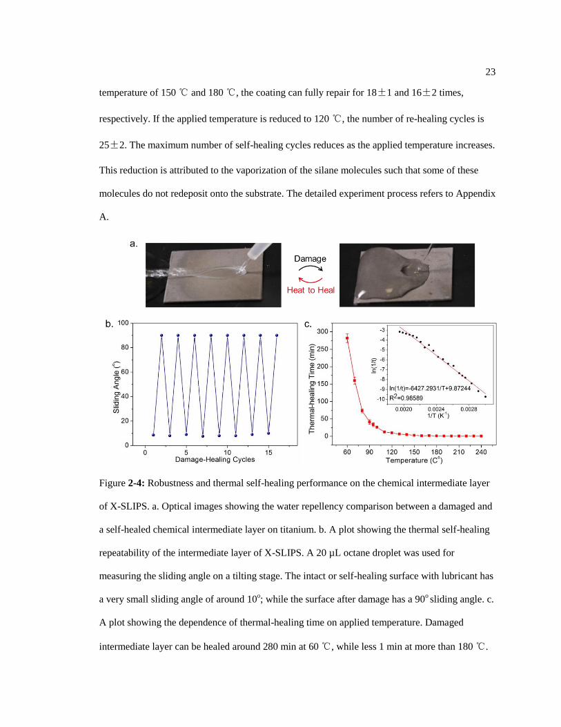
23
temperature of 150 ℃ and 180 ℃, the coating can fully repair for 18±1 and 16±2 times,
respectively. If the applied temperature is reduced to 120 ℃, the number of re-healing cycles is
25±2. The maximum number of self-healing cycles reduces as the applied temperature increases.
This reduction is attributed to the vaporization of the silane molecules such that some of these
molecules do not redeposit onto the substrate. The detailed experiment process refers to Appendix
A.
Figure 2-4: Robustness and thermal self-healing performance on the chemical intermediate layer
of X-SLIPS. a. Optical images showing the water repellency comparison between a damaged and
a self-healed chemical intermediate layer on titanium. b. A plot showing the thermal self-healing
repeatability of the intermediate layer of X-SLIPS. A 20 µL octane droplet was used for
measuring the sliding angle on a tilting stage. The intact or self-healing surface with lubricant has
a very small sliding angle of around 10o; while the surface after damage has a 90
o sliding angle. c.
A plot showing the dependence of thermal-healing time on applied temperature. Damaged
intermediate layer can be healed around 280 min at 60 ℃, while less 1 min at more than 180 ℃.
24
The semi-log plot shows that the self-healing rate and the heating temperature fits the Arrhenius
relationship. In the inset, t is the thermal healing time in second, and T is heating temperature in
Kelvin. The sample for this experiment is silanized titanium. Error bars indicate standard
deviations for three independent measurements.
Furthermore, we investigated the relationship between the repairing temperature and the
time for the complete healing of the chemical functionalized layer (Figure 2-4). To investigate
this relationship, we first treated the silanized titanium surface with oxygen plasma to damage the
surface functional group, and then heated the substrate at different temperatures for specific time
intervals until the surface hydrophobicity was recovered. Thermal-healing time is highly
dependent on the heating temperature. For example, it takes less than 5 min at temperature higher
than 150 ℃ for complete healing, whereas the healing would take ~300 min at temperature of 60
℃. The temperature dependence of healing time follows the Arrhenius equation (Figure 2-4),
which can be expressed as,
1
ln( ) ln( )aEk A
R T
(2-1)
where k is the self-healing rate at the absolute temperature T (in kelvins) – here we
consider the reciprocal of time (s-1
) to be the self-healing rate. A is the pre-exponential factor, Ea
is the activation energy, and R is the universal gas constant (8.31 kJ/kmol·T). This equation
allows us not only to predict the time required for the self-healing to occur at a specific
temperature, but also to understand the thermal-healing mechanism. The activation energy of self-
healing (Ea = 53.3 kJ/mol) is in line with the vaporization enthalpy (of the perfluorinated silane
on the surface (i.e., on the order of 50 – 65 kJ/mol), [79] which suggests that vaporization of the
silane molecules is the dominant driving force for the thermal-healing process. We further
confirmed the vapor phase transfer of silane experimentally and showed that the process can
occur for temperatures from 200 ℃ down to 60 ℃. (Figure 2-5)
25
Figure 2-5: Demonstration of silane evaporation upon substrate heating. a. Silicon wafer 1 is
etched with microstructures and is highly hydrophilic. b. Silicon wafer 2 is a silanized surface
with etched microstructures and is highly hydrophobic. c, d. Schematic showing the experimental
setup. Note that wafer 2 was in contact with the hot plate and was heated at a temperature of at 60
oC for >3 hours or 200
oC for 10 min. e. After the heating process, the wafer 1 was observed to
become hydrophobic, confirming that part of the silane molecules were transferred from wafer 2
to wafer 1.
2.4 Robustness Characterization
In addition to the chemical damage of the functionalized layer, we also applied physical
damages to the surfaces and demonstrated the thermal self-repairing of the substrate. In the first
physical test, we investigated the coating adhesion of the silanized textured surfaces as compared
to that of a commercially available spray-coated superhydrophobic surface. We used a scotch
tape to attach the surfaces with a weight of 5 N (pressure of 12.5 kPa) and subsequently detach
the tape from the surfaces. For the commercially available superhydrophobic surfaces, the coating
lost its superhydrophobicity after 15 times of peeling-and-detachment cycles (see Figure 2-6). As
a comparison, the silanized textured surfaces can last for at least 50 peeling-and-detachment
cycles without degrading the liquid-repellent performance. This indicates that the chemical
functionalization layer has a very strong adhesion with the base textured substrate.
26
In the second physical test, we investigated the scratch resistance of the X-SLIPS coating.
We used a sandpaper to create mechanical abrasions on a lubricated and non-lubricated nano-
textured aluminum substrate (see Supporting Information). Specifically, the lubricated coatings
can survive over 200 physical damage cycles than the non-lubricated coatings (~ 5 cycles) due to
the greatly reduced friction (Figure 2-7). In addition, with harder materials, for example titanium,
the surface textures have higher strength and therefore higher scratch resistance. By heating at
150 ℃ for 10 min, the X-SLIPS on aluminum substrate restore its liquid repellency shown in the
images in Figure 4a. The thermal healing process for lubricated aluminum surfaces generally
takes longer time than those of non-lubricated surfaces because the silane is limited to thermal
migration (i.e., the lubricant layer protects the silane from vaporizing). Unlike the chemical
damage where the silane layer is uniformly reacted or removed across the whole substrate,
mechanical abrasion removes the silane by destroying the surface texture of the substrate. The
undamaged silane coatings present near the mechanically damaged areas then serve as reservoirs
to replenish the silane coating upon heating. We have further demonstrated that the physically
damaged substrate can be thermally self-healed on different materials, such as glass, ceramic and
polyethylene (Figure 2-6).
Figure 2-6: Coating adhesion test for the silanized textured surface and a commercial
surperhydrophobic coating. a. Performance comparison of the coating adhesion between the

27
silanized textured surface and the superhydrophobic coating. The adhesion test protocol includes
the use of a scotch tape to adhere onto the testing surface with a 5 N weight on top of it. The tape
was then peeled off from the surface. After each peeling test, we measured the sliding angle of a
20 μL droplet of deionized water. Low sliding angle indicated that the surface is slippery. b. Real
time images showing water repellency performance on the two surfaces after the scotch tape
peeling test. After 20 times of peeling, the commercial superhydrophobic coating completely lost
its superhydrophobicity; while our silane coating still maintained its liquid repellency. Water is
colored with blue dye for visual representation.
Our coating method can be extended on most materials, such as metals (stainless steel,
aluminum, copper, titanium, etc.), glass, ceramics, and plastics (e.g., polyethylene) and a variety
of surface geometries (Figure 2-8). In Figure 2-8, commonly used industrial materials, stainless
steel, aluminum, titanium, glass, copper, carbon steel, ceramic, and polyethylene, are coated with
a perfluorinated silane and lubricated with perfluorinated oil (Dupont Krytox®). These surfaces
can repel aqueous fluids, hydrocarbons and other organic fluids with a broad range of surface
tensions ranging from ~21.6 mN/m (octane) to ~72.8 mN/m (water). The contact angle hysteresis
of these liquids on the lubricated surfaces is typically less than 5 degrees. In supporting videos 4
and 5, a coated ceramic can repel viscous complex liquids, such as ketchup (aqueous-based) and
mustard (oil-based). We have shown that these coated materials can be thermally healed under
large area chemical or physical damage. The robustness and self-repairing nature of our surfaces
will provide a robust and universal solution that could address many of the “sticky” problems in a
broad range of industrial, medical and daily life applications.

28
Figure 2-7: Self-repair of X-SLIPS coating. a. A plot showing the physical abrasion performance
comparison between lubricated and non-lubricated samples. Each abrasion cycle involved
dragging a sandpaper of average particle size of 470 µm along with a pressure of 15.6 kPa across
the surface with a velocity of ~0.02 m/s. b. Optical images showing the thermal repair of X-
SLIPS on glass, polyethylene, and ceramic. The coating was damaged by physical abrasion of
sandpaper.
Figure 2-8: Liquid repellency of X-SLIPS coating on various materials. a. A plot showing the
contact angle hysteresis of various liquids on the slippery surfaces. Inset shows a dodecane

29
droplet sliding with a very small sliding angle (less than 3°) on a coated carbon steel substrate,
indicating the super slippery nature of the surfaces. Error bars represent the standard deviations
for at least four independent measurements. b. The coating method can be applied to various
substrates such as stainless steel, aluminum, titanium, glass, copper, carbon steel, ceramic, and
polyethylene. The yellow droplet is 10 μL dyed octane. c. Comparison of untreated and X-SLIPS-
coated stainless steels of different surface geometries (flat plate, pipe section, and sphere) for the
repellency of dyed octane (in yellow).
2.5 Chapter Summary
Drawing inspirations from the wax repair of plant leaves and the slippery surfaces of the
Nepenthes pitcher plants, we have developed a cross-species bioinspired slippery coating that can
perform self-repair function upon thermal stimulation. We stress the importance of healing the
intermediate chemical functional layer as it is crucial for the proper function and longevity of the
slippery surfaces. The resulting surfaces can be applied onto a range of metals, glass, and plastics
with different surface geometries, and can self-repair even with critical large area physical
damage. The robustness and self-repairing nature of our surfaces will provide a robust and
universal solution that could address many of the “sticky” problems in a broad range of industrial,
medical and daily life applications.

Chapter 3
Viscoelastic solid repellent surfaces
3.1 Motivation of the Study
Water shortage is one of the most pressing global issues [80]. In 2016, a report showed
that 4 billion people in the world are facing severe water scarcity [81]. Meanwhile, it is estimated
that over 141 billion liters of water – nearly 6 times the daily water consumption of the entire
population in Africa [82] – is consumed globally everyday by toilet flushing alone [83]. A
number of approaches have been proposed to reduce fresh water consumption for toilet flushing
that range from the use of rainwater for flushing [84] to the use of self-contained dry toilets [85].
Owing to the great variety of complex factors such as local environment [86], resource
availability [87], and user preference [88], none of these approaches can completely address the
water consumption issue. A relatively unexplored approach is to engineer the material interface of
toilet surfaces to significantly weaken the adhesion of human feces and urine to reduce the
consumption of fresh water.
Surfaces that can repel various aqueous fluids (e.g., urine) are widely available such as
superhydrophobic surfaces and slippery liquid-infused porous surfaces (SLIPS) [5, 7, 8, 49, 56,
89-91]; however, it is more challenging to develop a surface to repel sticky viscoelastic solids
such as human feces whose viscosities can span from watery-like liquid to hard solid [92]. Owing
to the large variations of liquid and solid compositions of human feces, most types of feces
exhibit highly complex viscoelastic behaviors, leading to their strong stickiness towards various
surfaces. To the best of our knowledge, no state-of-the-art liquid repellent surfaces (i.e.,

31
superoleophobic or superhydrophobic surfaces or SLIPS) have demonstrated repellency against
viscoelastic solids with dynamic viscosity higher than ~100 Pa·s (Figure 3-1).
Figure 3-1: Overview of state-of-the-art liquid and viscoelastic solid repellent surfaces. (A)
Schematic and optical images showing the comparison of adhesion between viscoelastic solids
and different engineered surfaces including a superhydrophobic glass (left), a SLIPS-coated glass
(center), and a LESS-coated glass (right). The superhydrophobic glass was created using a

32
commercially available superhydrophobic coating (NeverWet, LLC). The SLIPS-coated glass has
an underlying surface roughness ~1 µm. Synthetic feces with a solid content percentage of 30%
(dynamic viscosity = ~2406 Pa·s) were used in these experiments. (B) A plot showing the
reported dynamic viscosity range of liquids and viscoelastic solids that can be repelled by the
state-of-the-art liquid repellent surfaces and the present work.
Here, we report the design and fabrication of liquid-entrenched smooth surfaces (LESS),
a sprayable, multifunctional surface coating designed to repel both aqueous fluids and
viscoelastic solids of dynamic viscosities spanning over 9 orders of magnitude (i.e, from ~10-3
Pa·s to ~105 Pa·s, see Figure 3-1). Distinct from the conventional liquid repellent surface design
principles [5, 7, 8, 89], our surface coating is designed based on the Dahlquist criterion (1966)
and interfacial adhesion analysis, together with rigorous thermodynamic considerations, in order
to achieve excellent viscoelastic solid repellency. LESS consist of a smooth solid surface that is
chemically functionalized to retain a microscopically thin layer of lubricant. Specifically, LESS
can be easily applied onto various hydrophilic surfaces within minutes, including materials
commonly used for toilets (e.g., ceramic, vitreous china, steel, etc.). Compared to traditional toilet
surfaces, LESS have shown significant reduction of adhesion to a wide range of viscoelastic
solids. In addition, we have shown that LESS can maintain non-stickiness toward human feces,
which outperforms other commercial and state-of-the-art materials such as ceramic, silicone,
Teflon, and SLIPS. Specifically, surfaces coated with LESS consume only ~10% of the water
required to completely clean an uncoated surface. We have also developed a displacement
wetting scheme that provides a simple and efficient mechanism to renew the surface for enhanced
coating robustness and longevity. Moreover, we have demonstrated that LESS possesses
excellent anti-biofouling properties comparable to the state-of-the-art antifouling coatings such as
SLIPS [56].
33
3.2 Design of Viscoelastic Solid Repellent Surfaces
3.2.1 Design Criteria I: Interfacial Adhesion
Adhesion between a viscoelastic solid and the underlying solid surface can be quantified
by the adhesion energy at the solid-to-solid interface. Specifically, the adhesion energy, Gc, can
be expressed as [93]:
Gc = wa Φv(da/dt, T, ϵ) (3-1)
where Φv is a mechanical loss function, which depends on crack growth rate da/dt,
temperature T, and strain ϵ of the viscoelastic solid, and wa is thermodynamic work of adhesion.
Since the crack growth rate and strain are inherit properties of the viscoelastic solid, reducing the
adhesion of the viscoelastic solid and the substrate surface would require lowering the work of
adhesion. Specifically, the work of adhesion can be expressed as wa = γ13 + γ23 – γ12, which can be
further simplified by Girifalco and Good equation [94] as:
wa = 2(γ13 • γ23)1/2
(3-2)
where γij is the interfacial energy at the i-j interface, and 1, 2, and 3 refer to the
underlying solid substrate, the viscoelastic solid, and air, respectively. In order to reduce the work
of adhesion, the interfacial energies of the underlying solid-air interface (γ13) and the viscoelastic
solid-air interface (γ23) would need to be reduced. Traditionally, there are two methods to
decrease these interfacial energies (γ13 and γ23, see Figure 3-2). The first method involves surface
chemistry modification of the underlying solid substrate (e.g. silanization), which can effectively
reduce γ13. The second method involves lubrication between the viscoelastic solid and the
substrate surface. As reported previously [95], the lubricant could be absorbed by the viscoelastic
solids instead of being adhered onto the substrate surface, resulting in the reduction of γ23. In
order to reduce both γ13 and γ23 concurrently, the lubricant would need to stably adhere on the

34
underlying surface so as to retain a thin layer of lubricant (Figure 3-2). In this specific case, the
adhesion interface changes from a solid-to-solid interface (i.e., viscoelastic solid-to-underlying
solid substrate) to a solid-to-lubricant interface (i.e., lubricant-infused viscoelastic solid-to-
lubricant-coated solid substrate). The detailed calculation can be found in Appendix B.
Figure 3-2: Schematics showing adhesion of viscoelastic solids on surfaces with different surface
treatments. Adhesion of viscoelastic solids on a) an untreated surface; b) a silanized surface; c) a
lubricated surface without chemical treatment; and d) lubricated surface with silanization
treatment.
In addition, the total work of adhesion between two surfaces is directly proportional to
their respective contact area, which could be significantly increased by the presence of roughness
[94]. In 1960s, Carl A. Dahlquist [96, 97] showed experimentally that when the storage modulus
of an adherent material is below a certain critical value (i.e., typically 0.3 MPa), the material will
begin to flow and form conformal contact with the surface roughness of the adherent regardless
of the applied pressure. This is widely known as the Dahlquist criterion, which has been the basis
for the design of pressure sensitive adhesives. For a viscoelastic material that satisfies the
Dahlquist criterion, any roughness present on the adherent would further increase the surface
adhesion. Therefore, reducing the surface roughness of the underlying solid substrate will be
another important method to further reduce the surface adhesion.
35
Figure 3-3: Measured viscoelasticity of synthetic feces. The storage and loss moduli of synthetic
feces with different solid content fraction (e.g. 10%, 20%, 30%, 40%, 50%, and 60% of solids in
synthetic feces). The solid and open symbols represent the storage modulus and the loss modulus,
respectively.
Figure 3-4: Comparison of the Dahlquist criterion with the measured storage moduli of different
synthetic feces. The storage moduli of synthetic feces with different solid content fraction (e.g.

36
10%, 20%, 30%, 40%, 50%, and 60% of solid in synthetic feces) under frequency of 1 rad/s. The
error bars represent standard deviations of storage moduli from three independent measurements.
To verify the adhesion mechanics of different surfaces, we prepared synthetic feces that
have organic solid content very similar to that of human feces [98] for adhesion characterization
on surfaces of varying roughness. The recipe of synthetic human feces was developed from the
original recipe developed at the University of KwaZulu Natal at South Africa. The synthetic
human feces are composed of yeast, psyllium, peanut oil, miso, polyethylene glycol, calcium
phosphate, cellulose, and water. All solid components are expressed as dry mass, and the
corresponding percentages are shown in Table 3-1. The compositions of the synthetic feces are
biologically very similar to human feces [98]. The viscosity of the synthetic feces can be tuned by
the percentage of solid contents. We made synthetic feces with solid percentage of 10%, 20%,
30%, 40%, 50%, and 60%. These synthetic feces were used within 5 hours of preparation for
viscoelasticity measurements, adhesion tests, and water consumption tests. Human feces can be
classified into 7 categories based on their solid content percentage and viscosities [92]. This
specific classification, known as Bristol stool scale, ranges from Type 1 (hard solids) to Type 7
(entirely liquid). A key reason for the use of synthetic feces is that one can control their
viscoelastic properties systematically by varying the corresponding solid content percentage
(Figure 3-3). The solid contents of the synthetic feces range from 10 wt% to 60 wt%, which
correspond to storage modulus of ~ 1 Pa (~10% solid content) to ~105 Pa (~60% solid content).
These values closely emulate those of the fresh human feces [99, 100]. Based on the Dahlquist
criterion, most of the synthetic feces used here would be conformally contacting the rough
surfaces, particularly for the synthetic feces whose storage moduli are much less than 0.3 MPa
(Figure 3-4). Our adhesion measurements showed that surface adhesion of the synthetic feces
increases with the surface roughness (with average roughness, Ra ranges from 0.87±0.06 nm to
4.12±0.26 µm), indicating a relatively smooth surface would be desirable in reducing surface

37
adhesion with feces. In accordance to Dahlquist criterion, LESS requires a relatively smooth
substrate for adhesion reduction which is in contrast to SLIPS where rough substrate is essential
for lubricant retention.
Table 3-1: Compositions of the synthetic feces.
Ingredients % dry mass Nutrition
Yeast 32.49 Biomass
Psyllium 10.84 Fibre
Peanut oil 17.31 Fat
Miso 10.84 Fibre/Protein/Fat
Polyethylene glycol 12.14 Carbohydrate
Calcium phosphate 10.84 Biomass
Cellulose 5.53 Carbohydrate
3.2.2 Design Criteria II: Interfacial Wetting
To satisfy the design criteria (i.e., forming a stable lubricant layer on a smooth substrate),
the lubricant has to preferentially adhere to a relatively smooth substrate, which would require
matching surface chemical affinity [49, 101]. Thermodynamically, to achieve this condition the
lubricant should have a positive spreading parameter S on the solid substrate and a positive
disjoining pressure П(e) [38, 39, 102] in the presence of both air and the foreign immiscible
liquid of interest (i.e., S > 0 and П(e) > 0), respectively. Here, we define the spreading parameters
of the lubricant on the solid substrate in the presence of air as Sls and that in the presence of the
foreign immiscible fluid droplet as Slsf, respectively. Specifically, these spreading parameters can
be expressed as Sls = σs – (σls + σl) and Slsf = σsf – (σls + σlf), where σs, σls, σl, σsf, and σlf are the

38
interfacial tensions of solid-air, lubricant-solid, lubricant-air, solid-immiscible fluid, and
lubricant-immiscible fluid interfaces, respectively.
In addition, the disjoining pressure of the lubricant film can be expressed as П(e) =
A/6πe3, where e is the lubricant film height, and A is the Hamaker constant expressed as[94]:
2 2 2 2
1/2 1/2 1/2 1/22 2 2 2 2 2 2 2
33
4 8 2
s l f lf ls l e
s l f ls l f l s l f l
n n n nhvA kT
n n n n n n n n
(3-3)
where k is the Boltzmann constant, T is the absolute temperature, h is the Planck’s
constant, and ve ~ 4×10¹⁵
s-1
is the plasma frequency of free electron gas, while ϵs/l/f and ns/l/f are
respectively the dielectric constants and refractive indices of the solid, lubricant, and immiscible
fluid of interest (air or water in our case), respectively.
Based on these criteria, we have designed a number of LESS coatings for silica-based
materials, such as glass, silicon, and china, etc. These substrates were chosen based on their
inherent smoothness (with Ra ~ 1 nm) and their hydroxyl groups availability, which made surface
functionalization facile [103]. Using these smooth substrates, we further functionalized these
surfaces with dimethyldimethoxysilane to create polydimethylsiloxane (PDMS)-grafted chemical
layer. In addition, silicone oil was chosen as the lubricating fluid due to its strong chemical
affinity towards the surfaces as well as its excellent chemical stability and low environmental
impact [104]. Our calculations of spreading parameters and Hamaker constants have shown that
this specific material combination (i.e., silicone oil and the PDMS-grafted surface) satisfies the
requirement for a stable lubricant film formation (i.e., S > 0 and A > 0, Tables 3-2), which are
consistent with our experimental observations. The formation of stable lubricant layer on a solid
surface requires that the lubricant should completely wet the solid surface and cannot be
displaced by immiscible foreign liquids. To achieve this, the spreading parameter S and the
disjoining pressure Π(e) of the lubricant on the solid surface should be positive under air and

39
foreign immiscible liquids of interest. Specifically, the spreading parameters under air (Sls) and
immiscible liquid (Slsf) conditions can be calculated using a method proposed by van Oss,
Chaudhury, and Good (vOCG) introduced in a recent publication [38], which are shown below:
( ) 2 2 2 2 4LW LW LW
ls s ls l s l l s s l l l lS (3-4)
( )
2 2 2 2 2 2
2 2 2 4
lsf fs ls fl
LW LW LW LW
s l f l l s s l l f f l
LW LW
f s s f f s l l
S
(3-5)
Note that σLW
indicates the Lifshitz-van der Waals component of the interfacial tension at
an interface; whereas σ+ and σ
- represent the acid and base terms of the polar component of the
interfacial tension, respectively [38]. The solid surface here is grafted-PDMS-coated glass. The
lubricant is silicone oil, and the foreign liquid is water or a perfluorinated fluid such as DuPont™
Krytox 101. Interfacial tensions of different material interfaces of consideration are listed in
Table 3-2. The sign of disjoining pressure can be determined by Hamaker constant, which can be
calculated with the dielectric constants and refractive indices of the materials of interest (see
Table 3-3). Based on the calculations from the spreading parameters and the disjoining pressures,
silicone oil can spread completely on PDMS-grafted smooth surfaces, and be able to repel
immiscible liquids, such as water and DuPont™ Krytox 101. These predictions are consistent
with our experimental observations.

40
Table 3-2: Surface energy components for materials at ambient environment.
Materials σ (mN/m) σLW
(mN/m)
σ+
(mN/m)
σ -
(mN/m)
PDMS 23.1 22.9 0 3.05
water 72.8 22.6 25.5 25.5
silicone oil 20.7 20.7 0 0
Krytox 101 16.6 11.9 0.019 0.155
Note: The interfacial tension values listed in the table were obtained from reference [38].
Table 3-3: Calculated spreading parameters (S) and Hamaker constant (A) for liquids on PDMS-
grafted glass.
solid lubricant foreign
fluid
ϵs ns ϵl nl ϵf nf A
(10-21
J)
S
(mN/m)
stable
lubrication
PDMS silicone air 2.32 1.4 2.6 1.41 1 1 2.07 1.85 Y
PDMS silicone water 2.32 1.4 2.6 1.41 80 1.33 0.233 29.7 Y
PDMS silicone K101 2.32 1.4 2.6 1.41 2.1 1.3 0.564 34.4 Y
PDMS water air 2.32 1.4 80 1.33 1 1 -8.42 -84.1 N
Note: K101 indicates Dupont™ Krytox 101 perfluorinated oil. All dielectric constants and
refractive indices listed in the table were obtained from reference [94] and [39].

41
3.3 Fabrication of Liquid-Entrenched Smooth Surfaces (LESS)
Figure 3-5: Fabrication of liquid-entrenched smooth surfaces (LESS). (A) Schematic illustration
showing a two-step spray coating process to form LESS. (B) Optical images showing the
individual coating processes on glass. The lubricant used was silicone oil and the blue testing
liquid was dyed water.
To form LESS on silica-based smooth substrates, we developed a two-step spray coating
process (Figure 3-5). The first step generates a chemical layer on the substrate, and the second
step creates an overcoat lubricant layer. Before the first step of surface functionalization, the
surfaces need to be rinsed with isopropanol and deionized water in order to remove the surface
contaminants and expose the hydroxyl groups. Once the surface is clean, a solution containing
silane molecules (e.g., dimethyldimethoxysilane) is sprayed onto the surface, allowing these
molecules to react with the hydroxyl groups and forming a PDMS-grafted layer on the substrate.
The silanized substrate then becomes hydrophobic and can repel both water and alkanes [91]. The
formation of the new surface functional group was confirmed by X-ray photoelectron
spectroscopy (XPS) measurements showing the formation of Si-O bonds associated with
dimethyldimethoxysilane (Figure 3-6). In the second step, the PDMS-grafted surface is

42
preferentially wetted by silicone oil, forming a stable lubricating layer. The two-step fabrication
process generally takes less than 10 minutes, and can be applied to other relatively smooth
hydrophilic materials such as ceramic, carbon steel, titanium, etc. LESS exhibited strong
repellency towards both aqueous liquids (contact angle = 105.5o±0.3
o and contact angle hysteresis
= 0.8o±0.2
o) and viscoelastic synthetic feces (see Figure 3-3) as compared to the uncoated surface,
superhydrophobic surface, and SLIPS-coated surface (Figure 3-5).
Figure 3-6: XPS characterizations of silicon element on untreated (e.g. glass) and PDMS-grafted
substrates. a, The peak of silicon element is originated from silicon dioxide, which is the main
component of glass. b, The peak of silicon element (Si 2p) is originated from silicon dioxide and
silicone, which confirmed the presence of the PDMS on the PDMS-grafted substrate.
3.4 Adhesion of LESS against Viscoelastic Feces
To test the anti-adhesion performance of LESS-coated surface, we performed systematic
surface adhesion measurements of the synthetic feces at different solid contents against other
control surfaces. In the adhesion measurements, the synthetic feces were brought into full contact
and then completely detached from the surfaces. The adhesion was quantified by the work of
debonding [105]. First, we investigated the importance of a stable lubricant layer for reducing

43
surface adhesion. The control surfaces in these tests include uncoated bare glass with and without
lubrication of silicone oil, and PDMS-grafted glass. We normalized the work of debonding of the
synthetic feces on lubricated surfaces (lubricated glass and LESS) by that of the uncoated bare
glass. Our results showed that lubrication on bare glass (without chemical functionalization) can
reduce the surface adhesion by ~41% for synthetic feces with 40% solid content (i.e., the stickiest
sample in the test). In comparison, grafted-PDMS glass can reduce the surface adhesion by
~75%, while the LESS coating can reduce the adhesion by ~90% (Figure 3-7). Qualitatively,
these experimental results are consistent to the predictions by Eq. 2. Our results indicate that the
presence of stable lubricating layer on the underlying solid substrate is critical to reduce surface
adhesion.
Figure 3-7: Adhesion comparison among different surfaces.

44
Figure 3-8: Adhesion comparison among surfaces with different roughness.
In the second set of tests, we investigated the influence of underlying surface roughness
of the lubricated substrates to the overall adhesion performance. The control surfaces in these
tests include uncoated glass and silicone-oil infused SLIPS samples with either microscale (Ra ~ 4
µm) or nanoscale roughness (Ra < 1 µm) on the underlying substrates (see Figures 3-7, 3-8). Our
measurements showed that the adhesion increases with increasing underlying surface roughness
(Figure 3-8). In general, the LESS-coated surface outperforms other control surfaces, including
uncoated surfaces with or without lubrication, and SLIPS with different underlying roughness.
According to these tests (Figure 3-6), LESS coating treatment can lead to 90% adhesion reduction

45
in synthetic feces (~40% solid content, with a viscoelasticity similar to a Type 3 – 4 healthy
human feces [99, 100]) compared to those of the uncoated surfaces.
The glass surface (VWR) was intrinsically smooth with a roughness less than 1 nm. We
created nanoscale porosity into the glass surfaces using an established protocol [90] by immersing
them into 0.5 mol/mL sodium bicarbonate solution, and boiling for 48 hr. The micro-roughened
glass was etched by two steps: first by using a universal laser systems VLS 2.3 (35% power and
90% cutting speed) and then by buffered oxide etch (6:1 40% NH4F in water to 49% HF in
water) for 20 minutes at room temperature. The surface roughness of all these glass slides and
other materials (e.g., ceramic, carbon steel, titanium, etc.) was measured either by an atomic force
microscope (AFM) in peak-force-tapping mode or an optical profilometer from Zygo, shown in
Figure 3-9.
Figure 3-9: Surface roughness measurement on different surfaces.
3.5 Water Consumption of LESS
3.5.1 Simulated Toilet Flushing
To simulate the condition of toilet flushing, we designed an open channel flow system
with 50 mm width, in which the flow rate can be precisely controlled. After measuring the height

46
of the flowing water level where the sample (i.e., synthetic feces) is located, we calculate the
hydraulic diameter as:
4
4 =h h
AD R
P (3-6)
where A is the flow area cross section, and P is the wetted perimeter. Based on the
hydraulic diameter, we can then estimate the Reynolds number as:
Re hD
vD
(3-7)
where v is the flow velocity, ρ is the water density, µ is the dynamic viscosity. Since all
the open-channel flow under investigations have Reynolds numbers ≥2500, these flows are in
turbulent flows and the wall shear can be estimated as:
.0.2 0.8 1.8
2 2
0.0225( ( 2 ))
4w
a h V
a h
(3-8)
where a is the flow width, and h is the flow height[106]. We also measured the height of
the flowing water level in a real toilet where the tilting of the surface is ~45o and performed the
same open channel flow calculation. The toilet we measured consumes 1.6 gallon per flush, and
each flush take ~5 s. The parameters of the flow were estimated as follows: 600 mm flow width,
300 mm from flushing outlet, and 3.97 mm flow height. Based on these parameters, the Reynolds
number is estimated as ~177000, and the corresponding wall shear is 0.74 Pa. The wall shear in
our open channel system under different flow rate is calculated as shown in Table 3-4. Note that
the wall shear in our system is in the same order of magnitude as those calculated for the real
toilet. Therefore, the open channel flushing system can realistically simulate the real toilet
flushing condition.

47
3.5.2 Water Consumption of Various Surfaces
A standard toilet in the United States uses ~1.6 gallon (~ 6 L) of water per flush [107]. To
investigate the amount of water that would be required to clean LESS after it is contaminated
with the synthetic feces, we built a simplified open-channel experimental setup to emulate the
toilet flushing process. Specifically, our setup is capable of generating a flow rate from 1 gallon
per minute (i.e., 3.8 L/min with Reynolds number, Re ~ 4570, calculated based on the hydraulic
diameter [106], see Supplementary section 6) up to 2.8 gallon per minute (i.e., ~10.6 L/min with
Re ~ 13100). The estimated wall shear stresses generated by these flows range from 0.093 Pa (at
1 gallon per min) up to 0.78 Pa (at 2.8 gallon per min), which are similar to those of typical toilets
(Table 3-4). To simulate the adhesion of feces to toilet surfaces during defecation, we dropped the
synthetic feces (~5 grams) from a height of ~400 mm onto the test surfaces at a tilting angle of
45o. We then put the surfaces inside our open channel flow system to determine the amount of
water required to completely remove the feces and their residues (Materials and Method, and fig.
S8). We verified the complete removal of the feces residues using fluorescent trace dye, which
was mixed with the synthetic feces during our tests (Figure 3-11). Compared to uncoated glass
surfaces, LESS-coated surfaces reduce water consumption by up to 90% for various synthetic
feces at different solid contents (Figure 3-12). We have also conducted similar characterizations
on SLIPS samples and found that the water consumption increases with increasing underlying
substrate roughness – a trend that is consistent with the observations in the adhesion tests (Figures
3-10 and 3-11).
Table 3-4: Physical parameters for the simulated-toilet flushing systems.
Flow Rate (gpm) 1 1.5 2 2.5 2.8
Height (mm) Re
Wall Shear (Pa)
4.75 4578 0.093
3.62 7136 0.33
5.11 9049 0.28
4.27 11632 0.60
4.15 13081
0.78

48
Figure 3-10: Water consumption on different surfaces under different flow rate with impact of
different feces.
Figure 3-11: Experimental setup of simulated flushing.
3.6 Adhesion against Human Feces
Finally, we compared the adhesion performance of human feces on LESS and other state-
of-the-art and commercially available surfaces (Figures 3-12, 3-13). Specifically, we used glazed
ceramic (a typical toilet material), Teflon, and silicone as the control surfaces. For these tests, we
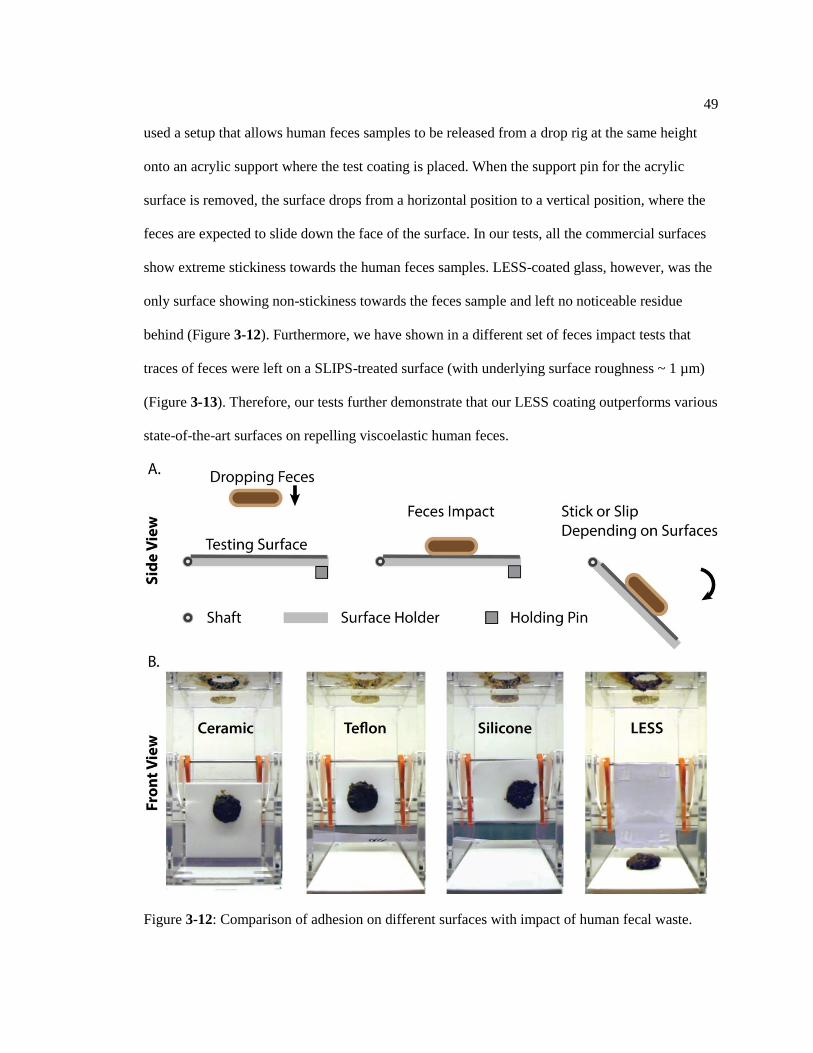
49
used a setup that allows human feces samples to be released from a drop rig at the same height
onto an acrylic support where the test coating is placed. When the support pin for the acrylic
surface is removed, the surface drops from a horizontal position to a vertical position, where the
feces are expected to slide down the face of the surface. In our tests, all the commercial surfaces
show extreme stickiness towards the human feces samples. LESS-coated glass, however, was the
only surface showing non-stickiness towards the feces sample and left no noticeable residue
behind (Figure 3-12). Furthermore, we have shown in a different set of feces impact tests that
traces of feces were left on a SLIPS-treated surface (with underlying surface roughness ~ 1 µm)
(Figure 3-13). Therefore, our tests further demonstrate that our LESS coating outperforms various
state-of-the-art surfaces on repelling viscoelastic human feces.
Figure 3-12: Comparison of adhesion on different surfaces with impact of human fecal waste.

50
Figure 3-13: Adhesion on SLIPS with impact of human fecal waste.
3.7 Anti-Bacterial Performance of LESS
One important reason that urinals or toilets need to be flushed and cleaned regularly is to
prevent the growth of bacteria and spread of infectious diseases. In certain regions (e.g., Brazil),
rainwater is used as the source for toilet flushing. However, rainwater can contain bacteria that
may contaminate the sanitation facilities [84]. Owing to the presence of the mobile lubricant
interface of LESS, we hypothesize that LESS may have comparable anti-biofouling performance
as state-of-the-art materials [56]. To verify this, we performed biofouling analyses on LESS-
coated substrate and other control surfaces using natural rainwater. Specifically, we collected
rainwater from a house roof in State College, PA, USA, and measured its bacteria content and
concentration (Figure 3-14).

51
Figure 3-14: Rainwater bacteria concentration measurement.
Table 3-5. Bacteria identification from mass spectrometry.
Organism
(best match)
Score
Value
Staphylococcus aureus 2.358
Enterobacter cloacae 2.281
Escherichia vulneris
Escherichia hermannii
Enterococcus mundtii
Acinetobacter calcoaceticus
2.256
2.212
2.219
2.077
Note: Any score value >2 indicates secure genus identification.
We identified the bacteria in the rainwater using a MALDI Biotyper system; and these
bacteria were identified as Staphylococcus aureus, Enterobacter cloacae, Escherichia vulneris,
Escherichia hermannii, Acinetobacter calcoaceticus, Enterococcus mundtii (Figures 3-15, 3-18,
Table 3-5), which are commonly found in rainwater [108]. We rinsed the LESS-coated substrate,
two SLIPS samples (one with underlying microscale roughness and the other with nanoscale

52
roughness), and uncoated bare glass with the collected rainwater for 1 min, and then immediately
incubated the substrates by attaching solid agar onto the surfaces in an incubator. After 36 hours
of incubation, we counted the bacterial colonies on these surfaces. Specifically, no observable
bacteria colonies were found on all SLIPS-coated and LESS-coated substrates; whereas the
untreated glass surfaces were contaminated with the bacteria in the rainwater (Figure 3-15). Our
results showed that the anti-biofouling performance of the LESS-coated substrate is comparable
to existing state-of-the-art anti-biofouling materials [56]. In addition to the rainwater tests, we
further characterized these surfaces with a mixture of E. coli and synthetic urine. 10 mL of this
contaminated urine was sprayed onto the test surfaces to simulate the urination process, followed
by the aforementioned procedures for the biofouling characterizations. Our test results are similar
to those found in the rainwater tests, where all of the SLIPS and LESS-coated samples showed no
observable bacteria colonies while the glass substrate showed significant contamination with
bacteria (Figure 3-15). We have further shown that SLIPS and LESS-coated substrates can repel
all bacteria-contaminated synthetic urine with a sliding angle of a droplet (10 µL) less than 5o
(Figure 3-16).
Figure 3-15: Bacteria adhesion measurement on different surfaces.

53
Figure 3-16: Sliding angle of urine on different surfaces.
It is interesting to note that in the case where the lubricant is fully depleted in SLIPS,
bacteria biofilm can attach onto rougher substrates persistently. Even after sterilization with
bleach and 70% of alcohol, there are still bacteria attached on the rough surfaces. In comparison,
the biofilms that are initially attached onto the lubricant-depleted LESS-coated surface can be
completely removed after the bleach sterilization (Figure 3-17). All of these results indicate that
LESS has excellent anti-biofouling performance and, therefore, could minimize the use of
disinfectants or other aggressive chemicals currently used for cleaning and sterilization.

54
Figure 3-17: Sterilization of liquid-infused surfaces with different underlying roughness.
Figure 3-18: Rainwater bacteria identification.

55
3.8 Durability of LESS
We have also investigated the durability of the LESS coating against realistic water flow
(i.e., 1 gallon/min to 2.8 gallon/min) and impact of synthetic feces. Specifically, the LESS coating
(with silicone oil of viscosity of ~20 cSt) can remain functional even after >100 flushes of water
at a flow rate of 2.8 gallon/min (Figure 3-20), as well as ~8 to 36 impact-and-flush cycles of
synthetic feces of various solid contents before further replenishment is required (Figure 3-20 and
Figure 3-19).
Note that typical thickness of LESS is <~3 µm and the estimated volume of lubricant
required to coat a typical toilet would be ~170 µL assuming a total surface area of 600 cm2 (as
compared to ~6 L of water per flush). Based on these characterizations, it is estimated that the
concentrations of the silicone oil in the flushed water is on the order of ~0.05 parts per million
[109] – a concentration that has shown with negligible impact to the environments [110].
Figure 3-19: Durability measurement on LESS with contamination of different feces.
Since LESS requires the use of lubricant for its function against aqueous liquids and
viscoelastic solids, it will be important to develop a lubricant replenishment strategy to renew the
surface in case the coating is depleted over time during toilet flushing. Since the PDMS-grafted

56
substrate of LESS is designed to adhere the silicone oil as opposed to aqueous liquids, it is
possible to replenish the lubricant layer by incorporating small amounts of silicone oil in the
flushing water so that the silicone oil can preferentially wet the surface through displacement
wetting (Figure 3-20). During the lubricant replenishment process, the following thermodynamic
condition has to be satisfied so that it is energetically favorable for the lubricant to displace the
aqueous liquid-wetted surface,
ΔE1 = σlcosθl – σfcosθf + σf – σl > 0 (3-9)
where σf represents the interfacial tension of the immiscible fluid-vapor interface, and θl
and θf, are the equilibrium contact angles of the lubricant and the foreign immiscible fluid on a
flat solid surface, respectively. Our experimental measurements (i.e., σf = 71.1±0.2 mN/m (water),
σl = 20.7±0.3 mN/m, θf = 106.5o±0.4
o, θl = ~ 0
o) have shown that Eq. (3-9) is satisfied (i.e., ΔE1 =
91.3 mN/m > 0) for the displacement wetting of the lubricant. Experimentally, we have further
shown that silicone oil wets the PDMS-grafted ceramic surface even when the surface has been
pre-wetted by water, and subsequently forms a functional layer to repel the water (Figure 3-20).

57
Figure 3-20: Durability and replenishment of the lubricant layer on LESS.
A critical criterion for displacement wetting is that the solid must be preferably wetted by
the lubricant rather than by the foreign liquid one wants to repel. To determine whether a solid
will be wetted by liquid B when liquid A already adheres onto the surface, we compare the total
interfacial energy of the individual wetting configurations. Specifically, configuration A refers to
the state where the smooth solid is wetted by the foreign liquid, and configuration B refers to the
state where the smooth solid is wetted by the lubricant. EA and EB represent the total interfacial
energies per unit area of the wetting configuration A and B, respectively. And σsf, σsl, σf, and σl
represent the interfacial tensions of the solid-immiscible fluid interface, solid-lubricant interface,
immiscible fluid-vapor interface, and lubricant-vapor interface, respectively. In order for the

58
lubricant to displace the foreign liquid and preferentially attach onto the solid substrate, wetting
configuration B should be at a lower energy state. To derive a thermodynamic relationship for the
displacement wetting from configuration A to configuration B, we have EA – EB > 0, which can
be further expressed as,
σsf – σsl > 0 (3-10)
In particular, Eq. (3-10) is reduced to experimentally measurable quantities with the use
of the Young equation [102], where we have,
σlcosθl – σfcosθf + σf – σl > 0 (3-11)
where θl and θf, are the equilibrium contact angles of the lubricant and the foreign
immiscible liquid on a flat solid surface, respectively.
3.9 Chapter Summary
In summary, we have developed a set of design criteria based on Dahlquist criterion and
interfacial adhesion and wetting analyses to design highly effective viscoelastic solid repellent
coatings against solids with dynamic viscosities over 9 orders of magnitude. Specifically, we
have created a facile and scalable LESS coating specifically designed to reduce adhesion to soft
viscoelastic solids (including both synthetic and human feces) with applications aimed to
minimize water consumption for sanitation and waste management. Our LESS coating can be
applied onto various clean hydrophilic surfaces (e.g. glass, ceramic, china, aluminum, titanium,
and carbon steel, etc.) within minutes through a simple two-step spray coating without the need to
access advanced deposition and fabrication facilities. More importantly, our LESS coating has
shown significant adhesion reduction (up to ~90%) for soft viscoelastic solids (with storage
modulus on the order of 1000 Pa) and requires only 10% of the cleaning water required for an
untreated control surface. The excellent anti-biofouling property of LESS could minimize not

59
only the bacteria attachment, but also the use of any aggressive chemicals currently used for
sterilization, thus reducing environmental impacts. In addition, the LESS coating can be
replenished through the displacement wetting mechanism, which offers a simple yet effective
surface renewal method. With over ~1 billion toilets and urinals around the world, it is
anticipated that the utilization of LESS in toilets and other sanitation facilities worldwide would
lead to significant water saving, allowing fresh water to be used for other essential human
activities such as irrigation for food production and sanitation to promote global health.

Chapter 4
Summary and Discussion
In this dissertation, I have addressed two of the major issues in some of the state-of-the-
art liquid repellent surfaces. The first one is the robustness of the slipper liquid-infused porous
surfaces (SLIPS). While SLIPS have shown great pressure stability and strong durability with a
self-healable lubricating layer, SLIPS could lose their liquid repellency if the intermediate
chemical layer is damaged. At the meantime, no suitable solutions have been proposed to enhance
the robustness of this chemical functional layer. Here, I have introduced a self-healing
mechanism into the chemical functional layer of slippery liquid-infused porous surfaces (SLIPS)
by a bioinspired approach. Inspired by the wax regeneration ability of plant leaves and the
slippery surfaces of the Nepenthes pitcher plants, I have developed a cross-species bioinspired
slippery coating (X-SLIPS) that can perform self-repair function upon thermal stimulation even
under large area physical and chemical damage. By characterizing the thermally self-healing
performance, I have explored the underlying mechanism of this phenomenon, providing a
valuable guidance of designing and fabricating such self-healable coating. With the enhanced
robustness, X-SLIPS will provide a universal solution that could address many of the durability
problems in a broad range of harsh working environment in industrial, medical and daily life
applications.
The second one is the viscoelastic solid repellency. Conventional liquid repellent surfaces
mostly require surface structure/roughness to either create a thin air layer or retain lubricant.
While this surface roughness requirement is beneficial to reduce contact or friction towards
liquids, it would instead dramatically increase the adhesion when the viscoelastic solid
61
conformally contacting the surface. In this dissertation, I have, for the first time, designed and
fabricated a slippery smooth surface coating that can repel not only liquids but also viscoelastic
sticky solids. I have developed a set of design criteria based on Dahlquist criterion and interfacial
adhesion and thermodynamic wetting analyses to design highly effective viscoelastic solid
repellent coatings against solids with dynamic viscosities over 9 orders of magnitude.
Furthermore, I have created a facile and scalable coating specifically designed to reduce adhesion
to soft viscoelastic solids, named as liquid-entrenched smooth surfaces (LESS) for saving water
from toilets. I have shown that LESS have significant adhesion reduction (up to ~90%) for soft
viscoelastic solids (with storage modulus on the order of 1000 Pa) and requires only 10% of the
cleaning water required for an untreated control surface. The excellent anti-biofouling property of
LESS could minimize not only the bacteria attachment, but also the use of any aggressive
chemicals currently used for sterilization.
To this end, many engineering opportunities emerge from this dissertation, leading to
some of the future studies for liquid/solid repellent surfaces. For example, state-of-the-art liquid
repellent surface manufacturing has covered most of the materials, except for some chemically
inert plastics. Plastics are one of the most widely used materials in industrial and biomedical
applications, and liquid repellency is usually a desired property for these applications. It remains
very challenging to chemically functionalize a plastic surface in order to achieve desired liquid
repellency. Inspired from a recent study about bio-adhesives [111], we may acquire the ability to
tune the surface chemistry of these plastics to make them more reactive to our functional low-
surface-tension chemicals. In this way, a novel fabrication method can be developed, and may
open up plenty of significant industrial and biomedical applications for liquid repellent surfaces,
for example, aeration membranes, face shield, ostomy bag, blood transfusion, etc.
62
Appendix A
Experiments on Fabrication and Characterization of X-SLIPS
Materials: Stainless steel 304, stainless steel 316, carbon steel, titanium, aluminum,
copper, glass, ceramics, polyethylene, polypropylene, polystyrene, and ABS were purchased from
McMaster-Carr Inc. 4-inch silicon wafers were purchased from Semiconductor Solutions, LLC.
Perfluorinated silane used in the experiment was (heptadecafluoro-1,1,2,2-
tetrahydrodecyl)trichlorosilane from Gelest Inc. Other types of silanes used in the experiments
included 1H,1H,2H,2H-perfluorodecyltriethoxysilane, trimethoxy(octyl)silane, and
trimethoxy(propyl)silane, all purchased from Sigma Aldrich Corporation. The chemical etchants
used for surface roughening were hydrochloric acid and ferric chloride acid both from Sigma
Aldrich Corporation. Sandpaper (grit 700) was purchased from 3M Company. The fluorinated
lubricant was DuPont Krytox oils (100 to 107) purchased from TMC Industries, Inc.
Surface Roughness Formation: Nanostructures can be formed on titanium surface
through etching using concentrated hydrochloric acid for 1 hour at 40 ℃. Stainless steel (304 and
316), carbon steel, and copper surfaces were etched with ferric chloride acid for 1 hour at 40 ℃ to
produce micro/nano structures. Aluminum surfaces were reacted with water vapor at 100 ℃ for
15 to 30 min, forming boehmite nanostructures.[112] We formed micro-structures on plastics,
including polyethylene, polypropylene, polystyrene, and ABS, through physical abrasion using
sandpaper. The glass surfaces were etched using a slow etching process where the sample was
immersed in 0.5 mol/mL of boiling sodium bicarbonate solution for 48 hours. The etching
process can form nano-porous structures on the surface.[113] Micro/nanostructures on silicon
were created by photo-lithography and deep reactive ion etch (DRIE). The ceramic was
intrinsically rough as received.

63
Chemical Functionalization and Lubrication: Before functionalizing the surface, the
roughened industrial metals, glass, ceramic, plastic, and silicon were cleaned and surface-
activated using oxygen plasma for 10 min. The materials were immersed in a silane solution
consisting of 1 – 4 mM of (heptadecafluoro-1,1,2,2-tetrahydrodecyl)trichlorosilane in ethanol.
During the silanization process, the solution was exposed to air. The surface chemical
functionalization process was completed upon the full evaporation of the solution which typically
took less than 24 hours. By heating the solution at 70 ℃, the evaporation can be accelerated to
less than 5 hours. The average thickness of the silane coating is ~ 2.40±0.01 µm on flat titanium
samples based on a 4 mM (heptadecafluoro-1,1,2,2-tetrahydrodecyl)trichlorosilane in ethanol.
The silane deposited onto the substrates is the byproduct of the reaction between
(heptadecafluoro-1,1,2,2-tetrahydrodecyl)trichlorosilane (C10H4Cl3F17Si) and ethanol
(C2H5OH):1H,1H,2H,2H-perfluorodecyltriethoxysilane (C16H19F17O3Si).[114] The chemical
functional intermediate layers created by these types of silane (e.g., 1H,1H,2H,2H-
perfluorodecyltriethoxysilane, trimethoxy(octyl)silane, and trimethoxy(propyl)silane) can all self-
repair under thermal stimulation (Figure S2). After chemically functionalizing the surface, the
surface was lubricated with perfluorinated oils by spraying or spin coating.
Thermal-Repairing Characterizations: We damaged the intermediate chemical layer of
X-SLIPS using oxygen plasma for 3 min. A plasma cleaner from Harrick Plasma was used for
oxygen plasma treatment in all of the experiments. The pressure in the plasma chamber is ~700
mTorr, and the maximum power is 30 W. The frequency is in the 10MHz range, and the
maximum voltage is 750 V. After the surface damage, we lubricated the surface with Krytox 101,
and then measured the sliding angle of a liquid droplet (i.e., 15 µL of octane) using a tilting stage
(Fowler adjustable v-block set). To repair the chemical layer, we heated up the substrate at
elevated temperature (e.g., from 60 ℃ to 200 ℃) for 5 to 15 min, and repeated the
aforementioned sliding angle measurement. A 20 µL octane droplet was used for measuring the

64
sliding angle on a tilting stage. The thermally repaired surface with lubricant has a very small
sliding angle of ~10°; while the surface after damage has a 90° sliding angle.
Physical Abrasion Test: The abrasion test was performed on lubricated (Krytox 100)
and non-lubricated aluminum surfaces, which were boehmitized and silanized. Each abrasion
cycle involved dragging a sandpaper (solid fraction of ~0.5) of average particle size of 470 µm
along with a pressure of 15.6 kPa across the surface with a velocity of ~0.02 m/s. After each 5
cycles, we measured the sliding angle of a 20 μL droplet with our tilting stage. The liquid
droplets used for the tests were decane for lubricated surfaces and deionized water for the non-
lubricated surfaces.

65
Appendix B
Calculation of Work of Adhesion
The work of adhesion, wa, at the feces and substrate interface can be simplified as wa =
2(γ13 • γ23)1/2
by the Girifalco and Good equation [94]. Health human feces contain ~70% of water
[92] with the rest consisting of organic matters. Therefore, we can estimate the upper bound of
their surface energy (γ13) to be similar to that of water [102] (i.e., γ13 ≤~72 mJ/m2). From previous
literature, glass surface [102] (γ23) has surface energy as 310 mJ/m2. Based on the aforementioned
equation, the work of adhesion between human feces and glass surface (wa0) is ≤299 mJ/m2.
There are three different methods to reduce the work of adhesion (Figure 3-2). The first method
involves silanization of the glass surface with grafted-polydimethylsiloxane (PDMS). Since the
grafted PDMS has nearly identical chemical structure as the silicone oil, one can assume their
surface energies to be similar. The surface energy of silicone oil is measured to be ~21 mJ/m2.
Therefore, the work of adhesion between the synthetic feces and a PDMS-grafted glass (wa1)
would be ~78 mJ/m2. In the second method, a lubricating layer (silicone oil) can be added in
between the feces and an untreated glass surface to reduce the adhesion. Since silicone oil is
preferably to be absorbed to feces, only the surface energy of feces (γ13) changes. Note that the
silicone oil could be partially or fully infused into the feces, therefore we assume that the surface
energy of feces (γ13) to be ~72 mJ/m2 ≥ γ13 ≥ ~21 mJ/m
2. As a result, the work of adhesion
between the synthetic feces and a silicone-oil lubricated glass (wa2) would be ~299 mJ/m2 ≥ wa2 ≥
~161 mJ/m2. The third method involves coating a lubricating layer between the feces and a
chemically treated glass so as to retain a thermodynamically stable lubricant layer on the
substrate. In this case, we have ~72 mJ/m2 ≥ γ13 ≥ ~21 mJ/m
2, and γ23 ≈ 21 mJ/m
2. Therefore, the
work of adhesion on the LESS-treated glass (wa3) is ~78 mJ/m2 ≥ wa3 ≥ 42 mJ/m
2. Overall, we
have wa2 > wa1 ≥ wa3 and this trend is consistent with the experimental measurements.

66
Appendix C
Identification of Bacteria in Rainwater
The bacteria in collected rainwater were identified in following processes.50 µL of
rainwater was spread uniformly onto four different agar mediums: Thermo Scientific™ Blood
Agar (TSA with Sheep Blood) Medium, Thermo Scientific™ MacConkey Agar Medium, BD
BBL CHROMagar Orientation (Figure 3-18), and BD BBL MHB agar. Then the bacteria were
incubated for 24 hours. Isolates were prepared for analysis using a direct transfer method
following a standard Bruker protocol. Individual colonies from 24-hour cultures were transferred
onto a MALDI target plate using a sterile pipette tip and allowed to dry. The cells were lysed by
applying 1 µL of 80% formic acid solution in water, samples were allowed to dry and 1 µL of 10
mg/mL HCCA matrix solution in 50% aqueous acetonitrile containing 2.5% trifluoroacetic acid
was applied to each sample and allowed to dry. A bacterial test standard (BTS; Bruker Daltonics)
was used for instrument calibration and as a positive control. Matrix blank spots were included in
each analysis to ensure that the target plate was thoroughly cleaned and there is no carryover
signal. MALDI mass spectra were acquired on a Bruker Ultraflextreme MALDI TOF/TOF mass
spectrometer in the linear, positive-ion mode. Spectra were processed using a factory default
processing method for the Biotyper application and searched against a Bruker library containing
entries of 6903 cellular organisms using MALDI Biotyper Version 3.1 software (Bruker). The
results are shown in Table 3-5.

References
[1] A. Cassie and S. Baxter, "Wettability of porous surfaces," Transactions of the Faraday
society, vol. 40, pp. 546-551, 1944.
[2] Y. Chong and N. Watanabe, "A novel composite having super hydrophobic property,"
Journal of Fluorine Chemistry, vol. 54, p. 43, 1991.
[3] W. Barthlott and C. Neinhuis, "Purity of the sacred lotus, or escape from contamination
in biological surfaces," Planta, vol. 202, pp. 1-8, 1997.
[4] Y. Kenigsberg and E. Shchori, "process for treating a porous substrate to achieve
improved water and oil repellency," ed: Google Patents, 1992.
[5] A. Tuteja, W. Choi, M. Ma, J. M. Mabry, S. A. Mazzella, G. C. Rutledge, et al.,
"Designing Superoleophobic Surfaces," Science, vol. 318, pp. 1618-1622, 2007.
[6] R. Helbig, J. Nickerl, C. Neinhuis, and C. Werner, "Smart skin patterns protect
springtails," PloS one, vol. 6, p. e25105, 2011.
[7] T. Liu and C.-J. Kim, "Turning a surface superrepellent even to completely wetting
liquids," Science, vol. 346, 2014.
[8] T.-S. Wong, S. H. Kang, S. K. Tang, E. J. Smythe, B. D. Hatton, A. Grinthal, et al.,
"Bioinspired self-repairing slippery surfaces with pressure-stable omniphobicity,"
Nature, vol. 477, pp. 443-447, 2011.
[9] H. M. Whitney and W. Federle, "Biomechanics of plant–insect interactions," Current
opinion in plant biology, vol. 16, pp. 105-111, 2013.
[10] H. F. Bohn and W. Federle, "Insect aquaplaning: Nepenthes pitcher plants capture prey
with the peristome, a fully wettable water-lubricated anisotropic surface," Proceedings of
the National Academy of Sciences of the United States of America, vol. 101, pp. 14138-
14143, 2004.
[11] D. Zhang, W. Zhang, J. Gu, T. Fan, Q. Liu, H. Su, et al., "Inspiration from butterfly and
moth wing scales: Characterization, modeling, and fabrication," Progress in Materials
Science, vol. 68, pp. 67-96, 2015.
[12] X. Gao, X. Yan, X. Yao, L. Xu, K. Zhang, J. Zhang, et al., "The dry‐style antifogging
properties of mosquito compound eyes and artificial analogues prepared by soft
lithography," Advanced Materials, vol. 19, pp. 2213-2217, 2007.
[13] S. Yang, N. Sun, B. B. Stogin, J. Wang, Y. Huang, and T.-S. Wong, "Ultra-antireflective
synthetic brochosomes," Nature communications, vol. 8, p. 1285, 2017.
[14] C. Mora, D. P. Tittensor, S. Adl, A. G. Simpson, and B. Worm, "How many species are
there on Earth and in the ocean?," PLoS biology, vol. 9, p. e1001127, 2011.
[15] Y. Zheng, X. Gao, and L. Jiang, "Directional adhesion of superhydrophobic butterfly
wings," Soft Matter, vol. 3, pp. 178-182, 2007.
[16] T. Mouterde, G. Lehoucq, S. Xavier, A. Checco, C. T. Black, A. Rahman, et al.,
"Antifogging abilities of model nanotextures," Nature materials, vol. 16, p. 658, 2017.
[17] J. P. Holmquist, A. Mancuso, P. Ostberg, and P. Axelsson, "Moisture barrier cone," ed:
Google Patents, 2007.
[18] R. Rakitov and S. N. Gorb, "Brochosomal coats turn leafhopper (Insecta, Hemiptera,
Cicadellidae) integument to superhydrophobic state," Proceedings of the Royal Society of
London B: Biological Sciences, vol. 280, p. 20122391, 2013.
68
[19] K. M. Wisdom, J. A. Watson, X. Qu, F. Liu, G. S. Watson, and C.-H. Chen, "Self-
cleaning of superhydrophobic surfaces by self-propelled jumping condensate,"
Proceedings of the National Academy of Sciences, vol. 110, pp. 7992-7997, 2013.
[20] A. Nakajima, K. Hashimoto, T. Watanabe, K. Takai, G. Yamauchi, and A. Fujishima,
"Transparent superhydrophobic thin films with self-cleaning properties," Langmuir, vol.
16, pp. 7044-7047, 2000.
[21] D. Quéré, "Non-sticking drops," Reports on Progress in Physics, vol. 68, p. 2495, 2005.
[22] Y. Liu, L. Moevius, X. Xu, T. Qian, J. M. Yeomans, and Z. Wang, "Pancake bouncing on
superhydrophobic surfaces," Nature physics, vol. 10, p. 515, 2014.
[23] D. Öner and T. J. McCarthy, "Ultrahydrophobic surfaces. Effects of topography length
scales on wettability," Langmuir, vol. 16, pp. 7777-7782, 2000.
[24] K. Koch, B. Bhushan, Y. C. Jung, and W. Barthlott, "Fabrication of artificial Lotus leaves
and significance of hierarchical structure for superhydrophobicity and low adhesion," Soft
Matter, vol. 5, pp. 1386-1393, 2009.
[25] R. Fürstner, W. Barthlott, C. Neinhuis, and P. Walzel, "Wetting and self-cleaning
properties of artificial superhydrophobic surfaces," Langmuir, vol. 21, pp. 956-961, 2005.
[26] X. Deng, L. Mammen, H.-J. Butt, and D. Vollmer, "Candle soot as a template for a
transparent robust superamphiphobic coating," Science, vol. 335, pp. 67-70, 2012.
[27] M. Ma, R. M. Hill, J. L. Lowery, S. V. Fridrikh, and G. C. Rutledge, "Electrospun poly
(styrene-block-dimethylsiloxane) block copolymer fibers exhibiting
superhydrophobicity," Langmuir, vol. 21, pp. 5549-5554, 2005.
[28] Y. Lu, S. Sathasivam, J. Song, C. R. Crick, C. J. Carmalt, and I. P. Parkin, "Robust self-
cleaning surfaces that function when exposed to either air or oil," Science, vol. 347, pp.
1132-1135, 2015.
[29] C. Peng, Z. Chen, and M. K. Tiwari, "All-organic superhydrophobic coatings with
mechanochemical robustness and liquid impalement resistance," Nature materials, vol.
17, p. 355, 2018.
[30] J. P. Rothstein, "Slip on superhydrophobic surfaces," Annual Review of Fluid Mechanics,
vol. 42, pp. 89-109, 2010.
[31] C. H. Choi and C. J. Kim, "Large slip of aqueous liquid flow over a nanoengineered
superhydrophobic surface," Physical Review Letters, vol. 96, p. 4, Feb 2006.
[32] N. Miljkovic, R. Enright, Y. Nam, K. Lopez, N. Dou, J. Sack, et al., "Jumping-droplet-
enhanced condensation on scalable superhydrophobic nanostructured surfaces," Nano
letters, vol. 13, pp. 179-187, 2012.
[33] R. Garrod, L. Harris, W. Schofield, J. McGettrick, L. Ward, D. Teare, et al., "Mimicking
a Stenocara beetle's back for microcondensation using plasmachemical patterned
superhydrophobic− superhydrophilic surfaces," Langmuir, vol. 23, pp. 689-693, 2007.
[34] Y. Lai, Y. Tang, J. Gong, D. Gong, L. Chi, C. Lin, et al., "Transparent
superhydrophobic/superhydrophilic TiO 2-based coatings for self-cleaning and anti-
fogging," Journal of Materials Chemistry, vol. 22, pp. 7420-7426, 2012.
[35] L. L. Cao, A. K. Jones, V. K. Sikka, J. Z. Wu, and D. Gao, "Anti-Icing Superhydrophobic
Coatings," Langmuir, vol. 25, pp. 12444-12448, Nov 2009.
[36] L. Mishchenko, B. Hatton, V. Bahadur, J. A. Taylor, T. Krupenkin, and J. Aizenberg,
"Design of ice-free nanostructured surfaces based on repulsion of impacting water
droplets," ACS nano, vol. 4, pp. 7699-7707, 2010.
[37] J. D. Smith, R. Dhiman, S. Anand, E. Reza-Garduno, R. E. Cohen, G. H. McKinley, et
al., "Droplet mobility on lubricant-impregnated surfaces," Soft Matter, vol. 9, pp. 1772-
1780, 2013.

69
[38] D. J. Preston, Y. Song, Z. Lu, D. S. Antao, and E. N. Wang, "Design of Lubricant Infused
Surfaces," ACS applied materials & interfaces, vol. 9, pp. 42383-42392, 2017.
[39] D. Daniel, J. V. Timonen, R. Li, S. J. Velling, and J. Aizenberg, "Oleoplaning droplets on
lubricated surfaces," Nature Physics, vol. 13, p. 1020, 2017.
[40] H. Liu, P. Zhang, M. Liu, S. Wang, and L. Jiang, "Organogel‐based Thin Films for
Self‐Cleaning on Various Surfaces," Advanced Materials, vol. 25, pp. 4477-4481, 2013.
[41] P. Kim, M. J. Kreder, J. Alvarenga, and J. Aizenberg, "Hierarchical or not? Effect of the
length scale and hierarchy of the surface roughness on omniphobicity of lubricant-infused
substrates," Nano letters, vol. 13, pp. 1793-1799, 2013.
[42] J. Cui, D. Daniel, A. Grinthal, K. Lin, and J. Aizenberg, "Dynamic polymer systems with
self-regulated secretion for the control of surface properties and material healing," Nature
materials, vol. 14, p. 790, 2015.
[43] X. Yao, Y. Hu, A. Grinthal, T.-S. Wong, L. Mahadevan, and J. Aizenberg, "Adaptive
fluid-infused porous films with tunable transparency and wettability," Nature materials,
vol. 12, p. 529, 2013.
[44] X. Dai, B. B. Stogin, S. Yang, and T.-S. Wong, "Slippery wenzel state," Acs Nano, vol. 9,
pp. 9260-9267, 2015.
[45] N. Vogel, R. A. Belisle, B. Hatton, T.-S. Wong, and J. Aizenberg, "Transparency and
damage tolerance of patternable omniphobic lubricated surfaces based on inverse
colloidal monolayers," Nature communications, vol. 4, p. 2176, 2013.
[46] D. Daniel, M. N. Mankin, R. A. Belisle, T.-S. Wong, and J. Aizenberg, "Lubricant-
infused micro/nano-structured surfaces with tunable dynamic omniphobicity at high
temperatures," Applied Physics Letters, vol. 102, p. 231603, 2013.
[47] P. Kim, T.-S. Wong, J. Alvarenga, M. J. Kreder, W. E. Adorno-Martinez, and J.
Aizenberg, "Liquid-Infused Nanostructured Surfaces with Extreme Anti-Ice and Anti-
Frost Performance," ACS Nano, vol. 6, pp. 6569-6577, 2012.
[48] M. J. Kreder, J. Alvarenga, P. Kim, and J. Aizenberg, "Design of anti-icing surfaces:
smooth, textured or slippery?," Nature Reviews Materials, vol. 1, p. 15003, 2016.
[49] D. C. Leslie, A. Waterhouse, J. B. Berthet, T. M. Valentin, A. L. Watters, A. Jain, et al.,
"A bioinspired omniphobic surface coating on medical devices prevents thrombosis and
biofouling," Nature Biotechnology, vol. 32, pp. 1134-1140, Nov 2014.
[50] S. Amini, S. Kolle, L. Petrone, O. Ahanotu, S. Sunny, C. N. Sutanto, et al., "Preventing
mussel adhesion using lubricant-infused materials," Science, vol. 357, pp. 668-673, 2017.
[51] B. J. Rosenberg, T. Van Buren, M. K. Fu, and A. J. Smits, "Turbulent drag reduction over
air- and liquid-impregnated surfaces," Physics of Fluids, vol. 28, p. 8, Jan 2016.
[52] S. Anand, A. T. Paxson, R. Dhiman, J. D. Smith, and K. K. Varanasi, "Enhanced
condensation on lubricant-impregnated nanotextured surfaces," ACS nano, vol. 6, pp.
10122-10129, 2012.
[53] R. Xiao, N. Miljkovic, R. Enright, and E. N. Wang, "Immersion condensation on oil-
infused heterogeneous surfaces for enhanced heat transfer," Scientific reports, vol. 3,
2013.
[54] X. Dai, N. Sun, S. O. Nielsen, B. B. Stogin, J. Wang, S. Yang, et al., "Hydrophilic
directional slippery rough surfaces for water harvesting," Science advances, vol. 4, p.
eaaq0919, 2018.
[55] S. Yang, X. Dai, B. B. Stogin, and T.-S. Wong, "Ultrasensitive surface-enhanced Raman
scattering detection in common fluids," Proceedings of the National Academy of
Sciences, vol. 113, pp. 268-273, 2016.
[56] A. K. Epstein, T. S. Wong, R. A. Belisle, E. M. Boggs, and J. Aizenberg, "Liquid-infused
structured surfaces with exceptional anti-biofouling performance," Proceedings of the

70
National Academy of Sciences of the United States of America, vol. 109, pp. 13182-
13187, Aug 2012.
[57] K. Golovin, S. P. Kobaku, D. H. Lee, E. T. DiLoreto, J. M. Mabry, and A. Tuteja,
"Designing durable icephobic surfaces," Science advances, vol. 2, p. e1501496, 2016.
[58] P. Irajizad, M. Hasnain, N. Farokhnia, S. M. Sajadi, and H. Ghasemi, "Magnetic slippery
extreme icephobic surfaces," Nature communications, vol. 7, p. 13395, 2016.
[59] G. B. Hwang, K. Page, A. Patir, S. P. Nair, E. Allan, and I. P. Parkin, "The Anti-
Biofouling Properties of Superhydrophobic Surfaces are Short-Lived," ACS nano, 2018.
[60] N. MacCallum, C. Howell, P. Kim, D. Sun, R. Friedlander, J. Ranisau, et al., "Liquid-
Infused Silicone As a Biofouling-Free Medical Material," Acs Biomaterials Science &
Engineering, vol. 1, pp. 43-51, Jan 2015.
[61] S. Sunny, G. Cheng, D. Daniel, P. Lo, S. Ochoa, C. Howell, et al., "Transparent
antifouling material for improved operative field visibility in endoscopy," Proceedings of
the National Academy of Sciences of the United States of America, vol. 113, pp. 11676-
11681, Oct 2016.
[62] J. Yin, M. L. Mei, Q. Li, R. Xia, Z. Zhang, and C. H. Chu, "Self-cleaning and
antibiofouling enamel surface by slippery liquid-infused technique," Scientific reports,
vol. 6, p. 25924, 2016.
[63] K.-C. Park, P. Kim, A. Grinthal, N. He, D. Fox, J. C. Weaver, et al., "Condensation on
slippery asymmetric bumps," Nature, vol. 531, pp. 78-82, 2016.
[64] A. Lafuma and D. Quéré, "Slippery pre-suffused surfaces," EPL (Europhysics Letters),
vol. 96, p. 56001, 2011.
[65] P. Wang, Z. Lu, and D. Zhang, "Slippery liquid-infused porous surfaces fabricated on
aluminum as a barrier to corrosion induced by sulfate reducing bacteria," Corrosion
Science, vol. 93, pp. 159-166, 2015.
[66] S. Yang, R. Qiu, H. Song, P. Wang, Z. Shi, and Y. Wang, "Slippery liquid-infused porous
surface based on perfluorinated lubricant/iron tetradecanoate: Preparation and corrosion
protection application," Applied Surface Science, vol. 328, pp. 491-500, 2015.
[67] C. Shillingford, N. MacCallum, T.-S. Wong, P. Kim, and J. Aizenberg, "Fabrics coated
with lubricated nanostructures display robust omniphobicity," Nanotechnology, vol. 25,
p. 014019, 2014.
[68] C. Schönecker, T. Baier, and S. Hardt, "Influence of the enclosed fluid on the flow over a
microstructured surface in the Cassie state," Journal of Fluid Mechanics, vol. 740, pp.
168-195, 2014.
[69] B. R. Solomon, K. S. Khalil, and K. K. Varanasi, "Drag reduction using lubricant-
impregnated surfaces in viscous laminar flow," Langmuir, vol. 30, pp. 10970-10976,
2014.
[70] S. Eigenbrode, "The effects of plant epicuticular waxy blooms on attachment and
effectiveness of predatory insects," Arthropod Structure & Development, vol. 33, pp. 91-
102, 2004.
[71] K. Koch, C. Neinhuis, H. J. Ensikat, and W. Barthlott, "Self assembly of epicuticular
waxes on living plant surfaces imaged by atomic force microscopy (AFM)," Journal of
Experimental Botany, vol. 55, pp. 711-718, 2004.
[72] K. Koch, A. Dommisse, and W. Barthlott, "Chemistry and crystal growth of plant wax
tubules of lotus (Nelumbo n ucifera) and nasturtium (Tropaeolum m ajus) leaves on
technical substrates," Crystal growth & design, vol. 6, pp. 2571-2578, 2006.
[73] K. Koch, B. Bhushan, H.-J. Ensikat, and W. Barthlott, "Self-healing of voids in the wax
coating on plant surfaces," Philosophical Transactions of the Royal Society of London A:
Mathematical, Physical and Engineering Sciences, vol. 367, pp. 1673-1688, 2009.
71
[74] L. Gao, A. Burnier, and Y. Huang, "Quantifying instantaneous regeneration rates of plant
leaf waxes using stable hydrogen isotope labeling," Rapid Communications in Mass
Spectrometry, vol. 26, pp. 115-122, 2012.
[75] X. L. Wang, X. J. Liu, F. Zhou, and W. M. Liu, "Self-healing superamphiphobicity,"
Chemical Communications, vol. 47, pp. 2324-2326, 2011.
[76] Q. Wei, C. Schlaich, S. Prevost, A. Schulz, C. Bottcher, M. Gradzielski, et al.,
"Supramolecular Polymers as Surface Coatings: Rapid Fabrication of Healable
Superhydrophobic and Slippery Surfaces," Advanced Materials, vol. 26, pp. 7358-7364,
Nov 2014.
[77] Y. Li, S. Chen, X. Li, M. Wu, and J. Sun, "Highly transparent, nanofiller-reinforced
scratch-resistant polymeric composite films capable of healing scratches," ACS nano, vol.
9, pp. 10055-10065, 2015.
[78] N. J. Chou, C. H. Tang, J. Paraszczak, and E. Babich, "MECHANISM OF OXYGEN
PLASMA-ETCHING OF POLYDIMETHYL SILOXANE FILMS," Applied Physics
Letters, vol. 46, pp. 31-33, 1985.
[79] G. R. Alcott, R. M. C. M. van de Sanden, S. Kondic, and J. L. Linden, "Vapor Pressures
of Precursors for the Chemical Vapor Deposition of Silicon-Based Films," Chemical
Vapor Deposition, vol. 10, pp. 20-22, 2004.
[80] J. Eliasson, "The rising pressure of global water shortages," Nature, vol. 517, pp. 6-7,
2015.
[81] M. M. Mekonnen and A. Y. Hoekstra, "Four billion people facing severe water scarcity,"
Science Advances, vol. 2, 2016.
[82] U. N. D. Programme, Human Development Report: UNDP, 2006.
[83] W. H. Organization and UNICEF, Progress on sanitation and drinking water–2015
update and MDG assessment: World Health Organization, 2015.
[84] E. Ghisi and D. F. Ferreira, "Potential for potable water savings by using rainwater and
greywater in a multi-storey residential building in southern Brazil," Building and
Environment, vol. 42, pp. 2512-2522, 2007.
[85] WWAP, "The United Nations World Water Development Report 2016: Water and Jobs,"
Paris, UNESCO, 2016.
[86] M. Mahdavinejad, M. Bemanian, S. F. Farahani, and A. Tajik, "Role of toilet type in
transmission of infections," Academic Research International, vol. 1, p. 110, 2011.
[87] C. Paterson, D. Mara, and T. Curtis, "Pro-poor sanitation technologies," Geoforum, vol.
38, pp. 901-907, 2007.
[88] J. Lin, J. Aoll, Y. Niclass, M. I. s. Velazco, L. Wunsche, J. Pika, et al., "Qualitative and
quantitative analysis of volatile constituents from latrines," Environmental science &
technology, vol. 47, pp. 7876-7882, 2013.
[89] A. Tuteja, W. Choi, J. M. Mabry, G. H. McKinley, and R. E. Cohen, "Robust omniphobic
surfaces," Proceedings of the National Academy of Sciences, vol. 105, pp. 18200-18205,
2008.
[90] J. Wang, K. Kato, A. P. Blois, and T.-S. Wong, "Bioinspired Omniphobic Coatings with
a Thermal Self-Repair Function on Industrial Materials," ACS Applied Materials &
Interfaces, vol. 8, pp. 8265-8271, 2016.
[91] L. Wang and T. J. McCarthy, "Covalently attached liquids: instant omniphobic surfaces
with unprecedented repellency," Angewandte Chemie, vol. 128, pp. 252-256, 2016.
[92] S. Lewis and K. Heaton, "Stool form scale as a useful guide to intestinal transit time,"
Scandinavian journal of gastroenterology, vol. 32, pp. 920-924, 1997.
[93] A. Kinloch, Adhesion and adhesives: science and technology: Springer Science &
Business Media, 2012.

72
[94] J. N. Israelachvili, Intermolecular and surface forces: Academic press, 2011.
[95] A. Gent and J. Schultz, "Effect of wetting liquids on the strength of adhesion of
viscoelastic material," The Journal of Adhesion, vol. 3, pp. 281-294, 1972.
[96] C. A. Dahlquist, "Pressure-sensitive adhesives," Treatise on adhesion and adhesives, vol.
2, pp. 219-260, 1969.
[97] E. Chang, "Viscoelastic properties of pressure-sensitive adhesives," The Journal of
Adhesion, vol. 60, pp. 233-248, 1997.
[98] C. Rose, A. Parker, B. Jefferson, and E. Cartmell, "The characterization of feces and
urine: a review of the literature to inform advanced treatment technology," Critical
reviews in environmental science and technology, vol. 45, pp. 1827-1879, 2015.
[99] S. Woolley, R. Cottingham, J. Pocock, and C. Buckley, "Shear rheological properties of
fresh human faeces with different moisture content," Water SA, vol. 40, pp. 273-276,
2014.
[100] S. Woolley, C. Buckley, J. Pocock, and G. Foutch, "Rheological modelling of fresh
human faeces," Journal of Water Sanitation and Hygiene for Development, vol. 4, pp.
484-489, 2014.
[101] M. Tenjimbayashi, R. Togasawa, K. Manabe, T. Matsubayashi, T. Moriya, M. Komine,
et al., "Liquid‐Infused Smooth Coating with Transparency, Super‐Durability, and
Extraordinary Hydrophobicity," Advanced Functional Materials, vol. 26, pp. 6693-6702,
2016.
[102] P.-G. De Gennes, F. Brochard-Wyart, and D. Quéré, Capillarity and wetting phenomena:
drops, bubbles, pearls, waves: Springer Science & Business Media, 2013.
[103] L. Zhuravlev, "Concentration of hydroxyl groups on the surface of amorphous silicas,"
Langmuir, vol. 3, pp. 316-318, 1987.
[104] M. Nendza, "Hazard assessment of silicone oils (polydimethylsiloxanes, PDMS) used in
antifouling-/foul-release-products in the marine environment," Marine Pollution Bulletin,
vol. 54, pp. 1190-1196, 2007.
[105] D. Martina, C. Creton, P. Damman, M. Jeusette, and A. Lindner, "Adhesion of soft
viscoelastic adhesives on periodic rough surfaces," Soft Matter, vol. 8, pp. 5350-5357,
2012.
[106] A. C. Yunus and J. M. Cimbala, "Fluid mechanics fundamentals and applications,"
International Edition, McGraw Hill Publication, vol. 185201, 2006.
[107] A. Vickers, "Water-use efficiency standards for plumbing fixtures: benefits of national
legislation," Journal (American Water Works Association), pp. 51-54, 1990.
[108] C. Evans, P. J. Coombes, and R. Dunstan, "Wind, rain and bacteria: The effect of weather
on the microbial composition of roof-harvested rainwater," Water research, vol. 40, pp.
37-44, 2006.
[109] N. Fendinger, D. McAvoy, W. Eckhoff, and B. Price, "Environmental occurrence of
polydimethylsiloxane," Environmental science & technology, vol. 31, pp. 1555-1563,
1997.
[110] D. Graiver, K. Farminer, and R. Narayan, "A review of the fate and effects of silicones in
the environment," Journal of Polymers and the Environment, vol. 11, pp. 129-136, 2003.
[111] T. S. Sileika, D. G. Barrett, R. Zhang, K. H. A. Lau, and P. B. Messersmith, "Colorless
multifunctional coatings inspired by polyphenols found in tea, chocolate, and wine,"
Angewandte Chemie International Edition, vol. 52, pp. 10766-10770, 2013.
[112] J. Yang, H. Song, H. Ji, and B. Chen, "Slippery lubricant-infused textured aluminum
surfaces," Journal of Adhesion Science and Technology, vol. 28, pp. 1949-1957,
2014/10/02 2014.

73
[113] T. Fujima, E. Futakuchi, T. Tomita, Y. Orai, and T. Sunaoshi, "Hierarchical nanoporous
glass with antireflectivity and superhydrophilicity by one-pot etching," Langmuir, vol.
30, pp. 14494-7, Dec 9 2014.
[114] F. Shi, L. Wang, and J. Liu, "Synthesis and characterization of silica aerogels by a novel
fast ambient pressure drying process," Materials Letters, vol. 60, pp. 3718-3722, 2006.

VITA
Jing Wang
November 14, 1989 Born, Xi’an, Shaanxi, China
2008 – 2012 Bachelor of Engineering
Department of Precision Instrument and Mechanology
Tsinghua University
Beijing, China
2012 – 2018 Graduate Student Researcher
Department of Mechanical and Nuclear Engineering
The Pennsylvania State University, University Park
Pennsylvania, the United States of America
2013 – 2014 PPG Graduate Research Fellow
The Pennsylvania State University, University Park
Pennsylvania, the United States of America
PUBLICATIONS
1. Jing Wang, Keiko Kato, Alexandre Blois, and Tak-Sing Wong, “Bioinspired Omniphobic
Coatings with Thermal Self-Repair Function on Industrial Materials”, ACS Applied
Materials & Interfaces, vol. 8, pp. 8265 – 8271 (2016).
2. Yu Huang, Birgitt Boschitsch Stogin, Nan Sun, Jing Wang, Shikuan Yang, and Tak-Sing
Wong, “A Switchable Cross-Species Liquid-Repellent Surface”, Advanced Materials,
vol. 29, 1604641 (2017).
3. Shikuan Yang, Nan Sun, Birgitt Boschitsch Stogin, Jing Wang, Yu Huang, and Tak-Sing
Wong, “Ultra-antireflective Synthetic Brochosomes”, Nature Communications, vol. 8,
1285 (2017).
4. Xianming Dai, Nan Sun, Birgitt Boschitsch Stogin, Jing Wang, Shikuan Yang, and Tak-
Sing Wong, “Hydrophilic Slippery Rough Surfaces for Water Harvesting”, Science
Advances, 4: eaaq0919 (2018).
PATENTS
1. Jing Wang and Tak-Sing Wong, United States patent application US 15/302,315 (2014).
2. Xianming Dai, Birgitt Boschitsch, Jing Wang, Nan Sun and Tak-Sing Wong, United
States patent application US 62/152,532 (2015).
3. Jing Wang and Tak-Sing Wong, United States patent application US 62/424,062 (2016).
4. Jing Wang, Birgitt Boschitsch, and Tak-Sing Wong, United States Patent Application No.
62/671,054 (2018).