bioconstructs methods for bio-inspired and bio...
TRANSCRIPT
1
BioConstructs – Methods for B io- Insp i red and B io-Fabr icated Des ign.
by
Kat ia Zolotovsky
B.A in Biology, B.Arch. in Architecture and Urban Planning Technion- Israel Institute of Technology, October 2006
Submitted to the Department of Architecture
in partial fulfillment of the requirements for the degree of
Master of Science in Architecture Studies at the
MASSACHUSETTS INSTITUTE OF TECHNOLOGY
September 2012 ©2012 Massachusetts Institute of Technology
All rights reserved
Author ............................................................................................................................... Katia Zolotovsky
Department of Architecture August 17, 2012
Certified by .......................................................................................................................
Terry Knight Professor of Design and Computation
Thesis Supervisor Certified by .......................................................................................................................
Christine Ortiz Professor of Material Science and Engineering
Thesis Supervisor
Accepted by .................................................................................................................... Takehiko Nagakura
Associate Professor of Design and Computation Chair of the Department Committee on Graduate Students
2
B ioConstructs – Methods for B io- Insp i red and B io-Fabr icated Des ign.
by
Kat ia Zolotovsky
Terry Knight Professor of Design and Computation
Thesis Supervisor
Chr ist ine Ort iz Professor of Material Science and Engineering
Thesis Supervisor
Mary Boyce Ford Professor of Engineering
Thesis Reader
Serg io Araya Professor at Universidad Adolfo Ibanez, Chile
Thesis Reader
3
Table of Contents Abstract Acknowledgements Chapter 1: Introduct ion
1.1 BioConstructs 1.2 Innovation in the use of computation and digital fabrication methods 1.3 Collaboration with scientific community 1.4 Bio-inspired design and biofabrication 1.5 Thesis structure Chapter 2: The Polypterus study
2.1 Introduction 2.2 Background: design principles of Polypterus armor 2.3 Parametric design system
2.3.1 Unit shape variation and description 2.3.2 Functional zoning and its relation to the unit shapes 2.3.3 Kinetic description of joints 2.3.4 Parametric schema of the unit 2.3.5 Generative modeling algorithm 2.3.6 Parametric assemblies 2.3.7 Quantification of functional performance
2.4 Discussion and future directions Chapter 2: The Xy l inus study
3.1 Biofabrication: design through control of material production by biological system 3.2 Presentation of ideas:
3.2.1 Microbial cellulose – material production by living cell 3.2.2 Synthetic Biology – genetic design of material properties 3.2.3 Bio 3d printer – genetically modified additive/subtractive material process
3.3 Materials and methods 3.4 Parametric design conditions 3.5 Observations 3.5.1 Obs_1: Inherit versus emergent material properties 3.5.2 Obs_2: Responsive design system. Regrowth. 3.5.3 Obs_3: Molded growth as structure 3.5.4 Obs_4: Molded post-growth structure 3.5.5 Obs_5: Layering of BC as analogy to biological 3d printer 3.6 Discussion and future directions Conclus ions L ist of f igures B ib l iography

4
to Jacob with love, for never ever giving up.
Acknowledgements I would like to express my gratitude to: Prof. Christine Ortiz, for her guidance and support. The more time I spend in the Ortiz group, the more fascinated I become with the way material is organized in living systems and its potential impact on design. I am thrilled to continue the work in Ortiz group during my PhD. There will be an articulated armor for human body! Prof. Terry Knight, from whom I learned so much. I would like to thank for her careful attention and patience, and for the clarity of her thought that clears away the confusion. Prof. George Stiny, for inspiring me continuously. His classroom is a rear place at MIT where I can hear myself think. I would also like to thank Prof. Boyce and Prof. Oxman for their valuable input to the work on Polypterus project. The members of Ortiz group I got a chance to work with – Yaning, Juha, Swati, Erica, and Matt – I learned so much from them. Jon Babb, the researcher in the Weiss Lab for Synthetic Biology. I remember our first conversation in winter 2011 about “living material-producing machines”. One week after Sergio and I were already growing bacterial cellulose in the corner of the Weiss lab and filling incubators with growth containers. I would like to thank Prof. Weiss for his support of this project. Sergio, the most amazing project mate I ever had. His creative ideas and unbreakable belief were the driving force of the Xylinum project. My Computation group – Sarah, Theodora, Carolina, Carl, Alan, Josh, Will, Moritz, and Masoud – I was lucky to be a part of this group of amazing people. Their intelligence, creativity and skills were a great source of inspiration for me. Laia and Jorge, for their help and their friendship. PhD candidates Duks and Rizal for always finding the time and attention to share their wisdom with me. Kiril, for his help with my English writing. And most importantly my family – mom, dad, Ola, and Boris – for their support and trust. And my mom again, for inspiring me with her love to academic research, and for her wisdom and advice. And my son Adam, for being my sunshine every day for the last eight years. All the people above made me believe I can do this and I can do much more…
5
Abstract This work presents experimentation with design and fabrication methods, using biological systems either indirectly (as a source of inspiration and information for design) or directly (as a material production for fabrication). The focus is on “bioconstructs”— design methods and processes that are invented and developed under the influence of biological systems. Two projects are presented. The Polypterus project examines the unique design principles of the armor of an ancient fish and possible ways to use these principles in the design of synthetic protective and flexible applications (bio-inspired design). The project deals with the correlation between geometrical data (units’ shape and rules of their composition on a surface) and functional data (anisotropic flexibility of the surface) to formulate a parametric design system. The Xylinus project focuses on the adaptation of material production by bacteria to a fabrication process (biofabrication). This fabrication method combines digital tools and technologies with material production by a living biological system. The long-term objective is to use cellulose-producing bacteria to develop an additive manufacturing technique for architecture and product design. Both projects suggest methods to utilize biological systems for innovative design and fabrication methods.
6
List of f igures Figure 1: P. Senegalus is an ancient fish with a unique armor system: while providing protection from predator attacks it allows the flexibility for the swimming motion of the fish. Figure 2: The armor consists of semi-helical rings that are mirrored along the top (dorsal) and bottom (ventral) lines of fish body. Figure 3: The combination of flexibility and protection in the armor is achieved through two levels of segmentation. Figure 4: Schematic assembly of the scales through two types of connections – overlapping and peg and socket. Figure 5: X-ray tomography data reconstruction of the scanned unit shapes. Figure 6: The functional parts of scale shape. Figure 7: The comparison between the shape of units in the same raw, different functional zones. Figure 8: The functional differentiation across the surface of the armor. Figure 9: Kinetic schema of relative motion of C09S10 and C48S10. Figure 10: Parametric schema of three-dimensional unit shape. Figure 11: Generative modeling algorithm for scales generation. Figure 12: The unit geometry defines the rules of its assembly on surface. Figure 13: All the modeled scales according to their positions. Figure 14: Parametric homogeneous assemblies of C09S10 and C48S10. Figure 15: Unit shape interpolation through morphing: the modeled sequence between c09s10 and c48s10. Figure 15: Multi-material homogeneous prototype.
7
Figure 17: Mold design and fabrication and experimental set up. Figure 18: The “rod-indicator method” experiment set up. Figure 19: Quantification of anisotropic mechanical behavior of the homogeneous prototype. F igure 20: Parametric variations of the original prototype geometry were introduced to tailor flexibility and mechanical anisotropy. F igure 21: The “rod-indicator method” was used to experimentally quantify the mechanical behavior of 3D prototypes. F igure 22: 3d scanning method – quantification of relative motions directly from the scan using Konica Minolta VIVID 910 3d scanner with GeoMagic software. F igure 23: Cellulose production by Acetobacter Xylinus. F igure 24: Growth process of microbial cellulose. F igure 25: Heterogeneous material distribution in microbial cellulose structure. F igure 26: Spontaneous variation in the initial growth. F igure 27: Regrowth: self-healing of the cellulose membrane. F igure 28: Molding in-vivo. F igure 29: Molding in-vitro. F igure 30 by Serg io Araya: Schematic diagram of layering structure of cellulose membrane growth.
8
Introduct ion
1.1 B ioConstructs
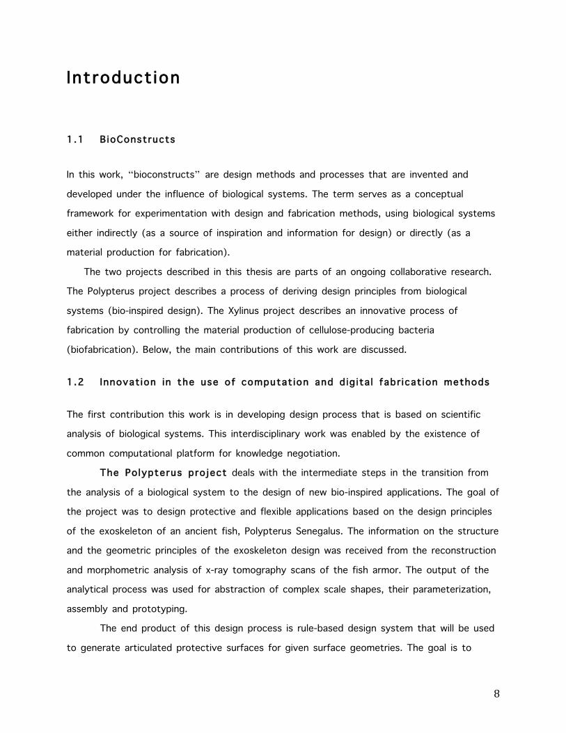
In this work, “bioconstructs” are design methods and processes that are invented and
developed under the influence of biological systems. The term serves as a conceptual
framework for experimentation with design and fabrication methods, using biological systems
either indirectly (as a source of inspiration and information for design) or directly (as a
material production for fabrication).
The two projects described in this thesis are parts of an ongoing collaborative research.
The Polypterus project describes a process of deriving design principles from biological
systems (bio-inspired design). The Xylinus project describes an innovative process of
fabrication by controlling the material production of cellulose-producing bacteria
(biofabrication). Below, the main contributions of this work are discussed.
1.2 Innovat ion in the use of computat ion and d ig ita l fabr icat ion methods
The first contribution this work is in developing design process that is based on scientific
analysis of biological systems. This interdisciplinary work was enabled by the existence of
common computational platform for knowledge negotiation.
The Polypterus project deals with the intermediate steps in the transition from
the analysis of a biological system to the design of new bio-inspired applications. The goal of
the project was to design protective and flexible applications based on the design principles
of the exoskeleton of an ancient fish, Polypterus Senegalus. The information on the structure
and the geometric principles of the exoskeleton design was received from the reconstruction
and morphometric analysis of x-ray tomography scans of the fish armor. The output of the
analytical process was used for abstraction of complex scale shapes, their parameterization,
assembly and prototyping.
The end product of this design process is rule-based design system that will be used
to generate articulated protective surfaces for given surface geometries. The goal is to
9
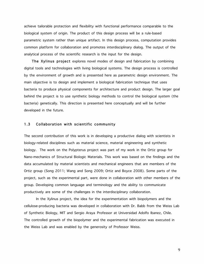
achieve tailorable protection and flexibility with functional performance comparable to the
biological system of origin. The product of this design process will be a rule-based
parametric system rather than unique artifact. In this design process, computation provides
common platform for collaboration and promotes interdisciplinary dialog. The output of the
analytical process of the scientific research is the input for the design.
The Xy l inus pro ject explores novel modes of design and fabrication by combining
digital tools and technologies with living biological systems. The design process is controlled
by the environment of growth and is presented here as parametric design environment. The
main objective is to design and implement a biological fabrication technique that uses
bacteria to produce physical components for architecture and product design. The larger goal
behind the project is to use synthetic biology methods to control the biological system (the
bacteria) genetically. This direction is presented here conceptually and will be further
developed in the future.
1.3 Col laborat ion with sc ient i f ic community
The second contribution of this work is in developing a productive dialog with scientists in
biology-related disciplines such as material science, material engineering and synthetic
biology. The work on the Polypterus project was part of my work in the Ortiz group for
Nano-mechanics of Structural Biologic Materials. This work was based on the findings and the
data accumulated by material scientists and mechanical engineers that are members of the
Ortiz group (Song 2011; Wang and Song 2009; Ortiz and Boyce 2008). Some parts of the
project, such as the experimental part, were done in collaboration with other members of the
group. Developing common language and terminology and the ability to communicate
productively are some of the challenges in the interdisciplinary collaboration.
In the Xylinus project, the idea for the experimentation with biopolymers and the
cellulose-producing bacteria was developed in collaboration with Dr. Babb from the Weiss Lab
of Synthetic Biology, MIT and Sergio Araya Professor at Universidad Adolfo Ibanez, Chile.
The controlled growth of the biopolymer and the experimental fabrication was executed in
the Weiss Lab and was enabled by the generosity of Professor Weiss.
10
This work looks for ways for the scientific and design communities to mutually contribute
to each other. On one hand, designers and architects can contribute their ability for
integrative thinking. Design process that is based on scientific analysis requires from the
designer the ability to be “productively ignorant” of the knowledge that does not serve the
design goal. Another aspect is the ability to think in terms of geometry and form, and see
the system behind the individual components. The process of thinking through making –
modeling, prototyping, experimenting with shapes and materials – is another way to
contribute to interdisciplinary research.
On the other hand, there are many aspects of the scientific analysis routine that can
contribute to architectural discipline as well. One such valuable lesson is that experimentation
includes cycles of failed experimentation, feedback and repeated experimentation. This
practice accumulates knowledge on the subject via iterative experiment, instead of using
one-attempt experimentation as it is commonly practiced in architectural disciplines.
1.4 Bio insp i red des ign versus B iofabr icat ion
This section will briefly summarize the two projects and their relation to each other. It will
also describe the main goals of the work on each project. The description of the projects is
organized in the table below. It addresses the main goals of the project by outlining what
the project is about, what is the methodology used, and why it is important.
Po lypterus pro ject {BIO-INSPIRED DESIGN}
The system of origin: protective and flexible exoskeleton of an ancient fish {S. POLYPTERUS}
WHAT: translation of a biological system to a parametric design method
HOW: knowledge negotiation between science and design method
WHY: design of articulated surfaces and bio-inspired joints
development of new analysis-informed design strategies
This project is dealing with the transition from the study of biological system to the
design of new protective and flexible application. This process of transition can be divided
into three main steps:
11
1. Study (analysis) of the system. The identification of main components and their
relation to each other.
2. Establishing the connection between the components of the system and the
functional performance. Identification and quantification of the main parameters in
play.
3. Design of new application with similar functional performance (synthesis) based on
the previous steps.
The work described here deals mainly step two above. It includes parameterization of unit
shape, parametric assemblies on flat surfaces and bending tests to quantify anisotropic
behavior of the assemblies.
Xy l inum project {BIO-FABRICATION}
The system of origin: cellulose-producing bacteria {A. XYLINUS}
WHAT: adaptation of a material process into fabrication process
HOW: knowledge negotiation between science and design methods
WHY: novel direct design-fabrication method, creating parametric conditions for the
material growth and distribution.
This project describes first steps of an innovative fabrication method. Cellulose-producing
bacteria is used to fabricate objects on a macro scale. A unique approach to fabrication with
living systems is proposed. The design process happens through controlling the environment
in which bacteria grow. The characteristics of material which is produced by bacteria are
designed on genetic level. The work described here deals with the following:
1. Initiation of material growth
2. Definition of the set up for growth as parametric environment
3. Description of experiments that attempt to control the generated shape by
modification of growth environment
4. Suggestion of conceptual construct of biological 3d printer for future research and
development.
12
1.5 Thes is structure
In the following chapters I will describe the work done on the two projects. Chapter 1 will
discuss the Polypterus project. Firstly, it will review the design principles of Polypterus armor.
Secondly, it will present the parametric design system for the armor. It will discuss the
functional differentiation, parametric unit shape, and the kinetic schema of relative motion in
the connections between units. Thirdly, the generative algorithm for 3D modeling of unit
shapes and parametric homogeneous assemblies will be described. Next, the gradual
transition between units through morphing will be discussed. Finally, experimental
quantification of functional performance for homogeneous 3D prototypes will be presented.
The Chapter will close with conclusions and future directions.
Chapter 2 will present the Xylinum project. The chapter will review the ideas that
guided experimentation with bacterial cellulose. It will explain the mechanism of material
production by bacteria. It will discuss the possibility of genetically engineering the bacteria to
achieve desired material properties, and also additive and subtractive modes of bacteria
activation. The idea of biological 3D printer will be conceptualized based on the above. Next,
the experimental part will be presented. The methods used will be mentioned. The idea of
the parametric design environment -- the environment for material growth -- will be
discussed in the frame of “design by environment”. Next, the experiments and observations
will be described and discussed. Lastly, the ideas for future development of this innovative
research will be presented.
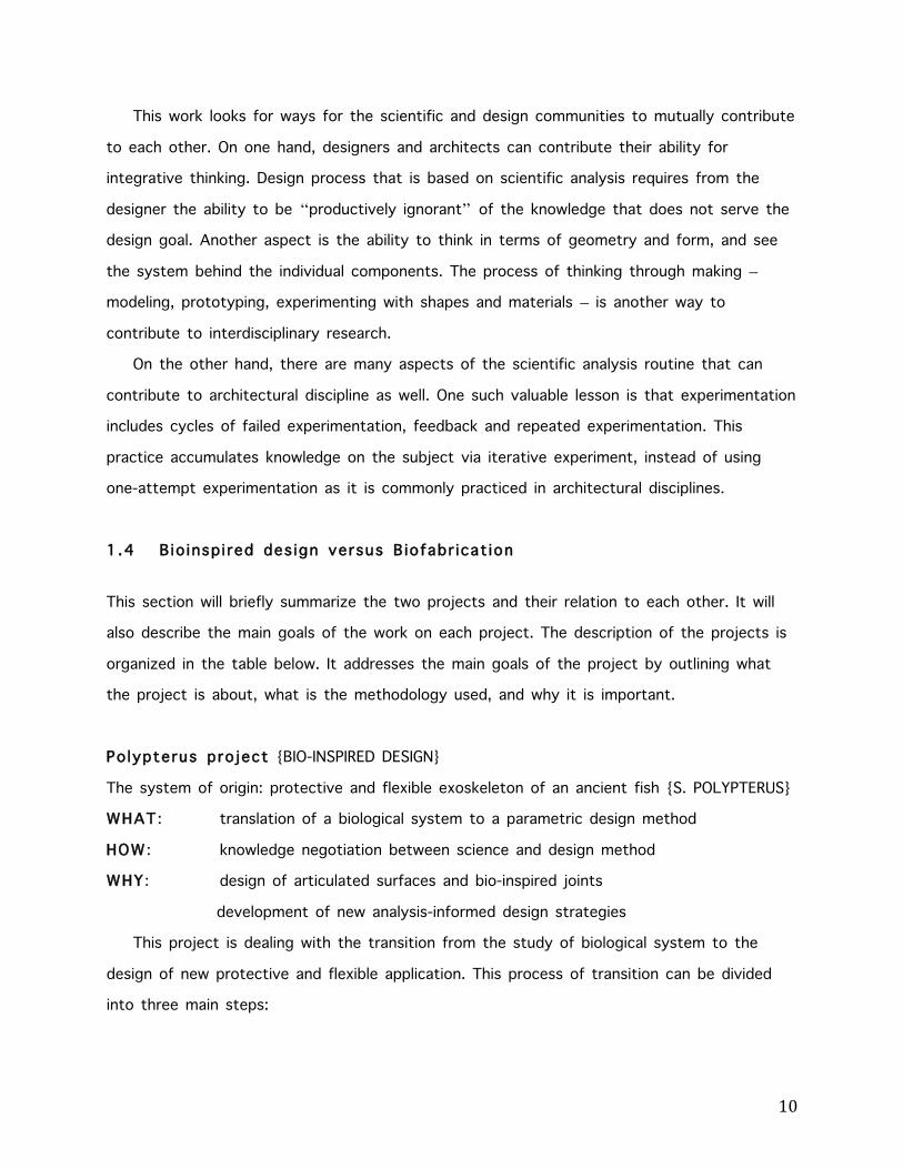
The Polypterus project 2.1 Introduct ion The Polypterus project examines an armor of an ancient fish, Polypterus Senegalus. This
armor is designed by nature to perform two seemingly contradictory functions: it provides
protection from predatory attacks yet allows the fish to swim and move freely
(F igure 1). The need for protection is addressed through a uniform layer of rigid (highly
mineralized) material across the body of the fish. The need for flexibility of motion is

13
resolved in segmentation of the armor into small units that move relative to each other. The
units are connected through convoluted morphological features with restricted degrees of
freedom. These joints provide anisotropic kinetic behavior to the armor. Nature provides a
unique solution to accommodate both protection and flexibility: an articulated surface that
constitutes of multiple components with convoluted geometry and articulated joints that
enable change due to motion of the fish. Previous studies describe mechanical functionality
of the individual scales (Bruet et al. 2008; Wang et al. 2009) and structural assessment and
biomechanical flexibility of the entire scale armor assembly (Pearson 1981; Brainerd 1994;
Gemballa 2002).
This study focuses on the description of the armor system as a parametric system. It
explores the functional differentiation of units across the surface of the armor. A parametric
design system is developed as an intermediate step for transition to a new functional
domain.
(from PhD thesis by J. Song, 2011 )
(photos by S.Reichert and J.Song, 2011)
F igure 1: P. Senegalus is an ancient fish with a unique armor system: while providing protection from predator attacks it allows the flexibility for the swimming motion of the fish.
Nature combines geometry-based and material-based design strategies to achieve
maximum performance (Ortiz and Boyce 2008). By studying these strategies we can develop
new design methodologies that will combine shape and material thinking. Furthermore, we
can design a new artificial system with similar functionality, such as body armors and
armored shields for vehicles.

14
The material-based principles in the design of Polypterus armor have been studied in
the Ortiz group and beyond (Sire 1989; Song 2011; Araya 2011). Geometry-based assembly
strategy of individual components into an armor system was previously described (Brainerd
1994; Gemballa and Bartsch 2002; Reichert 2011). In the previous study of geometric
principles of the Polypterus system, the following main steps were taken (Reichert 2011):
1) Individual scales were scanned using x-ray tomography to study the units’ shape
2) General rules of assembly of individual components into fish armor with anisotropic ranges
of motion were described based on the x-ray tomography data
3) A simplified unit was 3D modeled and a homogeneous composition was assembled on a
flat surface.
This thesis proposes the following steps toward the transition of the system to a new
functional domain for flexible and protective applications:
1. Parameterization of the system:
New data from full μCT profile of fish armor showed variation in the size and shape
of scales. Based on this variation, a parametric description of the unit shape was
created. Following this parametric description, a generative modeling algorithm was
developed.
2. Parametric assemblies:
In the biological model (the fish) the unit shapes vary across the surface of the
armor. This variation is due to local geometrical and functional characteristics of the
surface:
Geometric: the body surface curvature and the local volume in section.
Functional: the required local range of motion (for example, the tail is much more
mobile and flexible than the front area).
The local unit shape determines the connections with adjacent units and the local
surface performance. Using a generative modeling algorithm, variations of unit
assemblies were generated.
3. Quantification of anisotropic flexibility:
Bending tests were performed on homogeneous multi-material prototypes. These tests
quantify the flexibility of the prototypes and their anisotropic mechanical behavior.
The effect of the different parameters of the unit shape on anisotropic behavior of

15
the prototype was measured. A unique “rod indication” method was developed to
track the relative motion between two neighboring units as a function of their
orientation.
2.2 Background: des ign pr inc ip les of Po lypterus armor This section summarizes the basic design principles of fish armor of P. Senegalus as
previously described in the literature (Brainerd 1994; Gemballa and Bartsch 2002; Reichert
2011). In general, the armor consists of scales that are connected through convoluted
features. These types of connections define the range of relative motion between scales.
The restricted ranges of motion between units define overall anisotropic flexibility of the
armor.
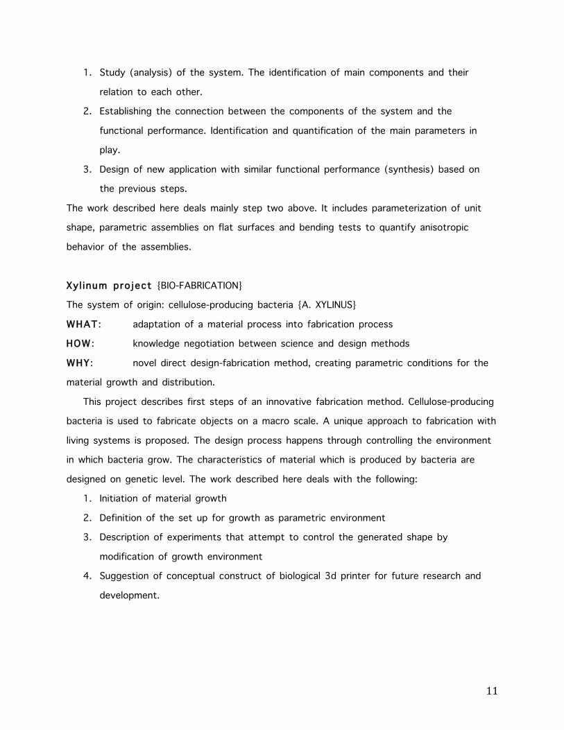
The armor has two levels of segmentation. On the first level, the armor consists of
an array of symmetric helical rings mirrored along the middle line of fish body as described
in F igure 2. These rings overlap between them and the relative sliding of the units
between the rings is one of the two mechanisms that provide flexibility to the armor. The
degree of overlapping varies across the surface of the armor and is largely defined by the
three dimensional unit shapes.
(S. Reichert, 2010)
F igure 2: The armor consists of semi-helical rings that are mirrored along the top (dorsal) and bottom (ventral) lines of fish body.
16
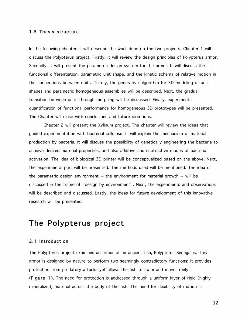
On the second level, the helical rings are subdivided into rhomboid-shaped segments
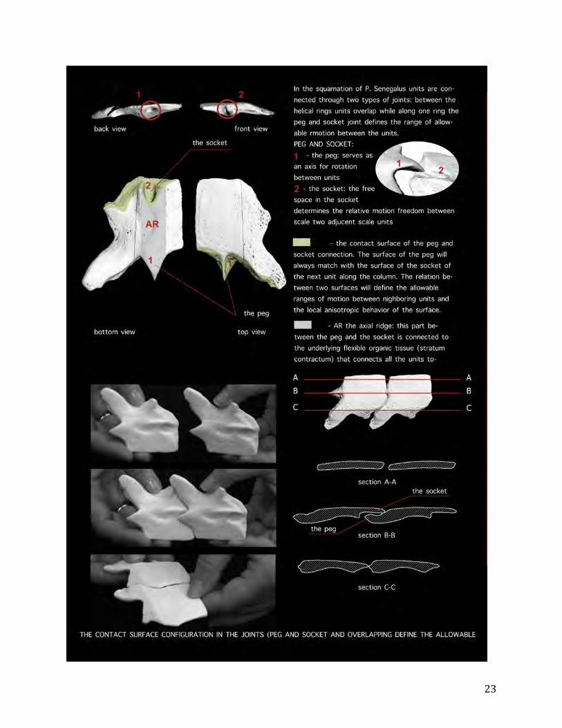
(the scales). The scales are connected through peg-and-socket joint. The surface of the peg
and socket connection defines the range of relative motions between the units as will be
further discussed in section 2.3.3. As the shape of the units vary in different areas of the
armor, the allowable ranges of motions are determined by the configuration of the contact
surface in the peg and socket connection. In addition to overlapping rings, this is the second
major mechanism responsible for the overall anisotropic flexibility of the system (F igure
3).
Figure 2
B
A
C
z
x
y
z
x
y
x
y
z
ß
Figure 2
B
A
C
z
x
y
z
x
y
x
y
z
ß
Figure 2
B
A
C
z
x
y
z
x
y
x
y
z
ß
Reichert, 2010)

17
F igure 3: The combination of flexibility and protection in the armor is achieved through two levels of segmentation.
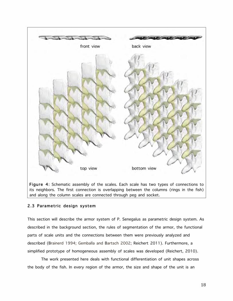
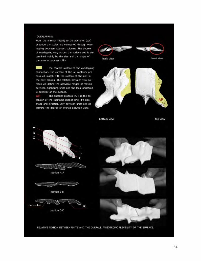
F igure 4 below shows the unfolded schematic assembly of scales in the armor. Each unit
has two types of connections to its neighbors: the overlapping between the columns and the
peg and socket connection between the scales in the column. Each type of connection while
assembled in linear array defines line of flexibility, a line of anisotropic flexibility. Below the
two types of lines – defined by two types of connections – are shown in two different
colors. The peg and socket connection is more restrictive then the overlapping in
determining the global flexibility of the surface. The anisotropic flexibility of the flat
homogenous assembly will be further discussed and experimentally quantified in section 2.3.8
Quantification of functional performance.
(Zolotovsky, 2012)
18
F igure 4: Schematic assembly of the scales. Each scale has two types of connections to its neighbors. The first connection is overlapping between the columns (rings in the fish) and along the column scales are connected through peg and socket.
2.3 Parametr ic des ign system
This section will describe the armor system of P. Senegalus as parametric design system. As
described in the background section, the rules of segmentation of the armor, the functional
parts of scale units and the connections between them were previously analyzed and
described (Brainerd 1994; Gemballa and Bartsch 2002; Reichert 2011). Furthermore, a
simplified prototype of homogeneous assembly of scales was developed (Reichert, 2010).
The work presented here deals with functional differentiation of unit shapes across
the body of the fish. In every region of the armor, the size and shape of the unit is an
19
indicator of the local anisotropic flexibility of the surface. By corresponding the geometrical
data (of units shape and rules of their composition on surface) and the functional data (local
anisotropic flexibility) it is possible to step away from analysis of an existing system to a
design of synthetic surfaces with tailorable local flexibility. The process involves identifying
the geometric parameters of unit shape at each location and establishing the correlation
between these parameters and the local functional performance.
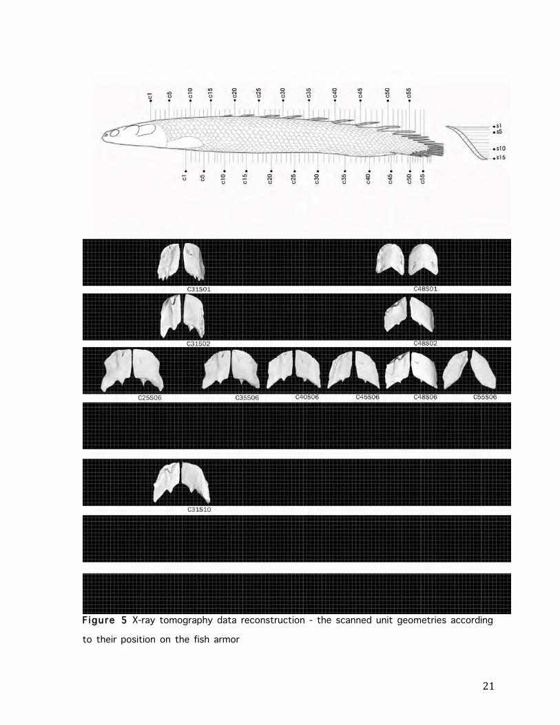
2.3.1 Unit shape var iat ion and descr ipt ion
The data on variation of unit shapes was collected through excising and x-ray tomography
scanning of scales from different positions on the body of the fish. The flow of information
in data analysis and the reconstruction of 3D shape of P.Senegalus scales were previously
described (Reichert 2010; Song 2011). In the resulting data set, each scale is registered
according to its position. Each helical ring is numbered from the head to the tail and
indicated as C (column number). The position of the unit on the ring is indicated as S (scale
number) counted from the top (dorsal) to the bottom (ventral) midlines of the fish body.
F igure 5 below summarizes the scanned unit geometries according to their position on the
body of the fish.

20
21
F igure 5 X-ray tomography data reconstruction - the scanned unit geometries according
to their position on the fish armor
22
Based on the x-ray tomography data, parametric design system of P. Senegalus armor
was created. The following steps are presented in this section:
1. Description of the unit shape and its functional parts including the contact surfaces
of the overlapping and the peg and socket joints (based on literature and
observation).
2. The parametric schema of the unit geometry that translates the variety in unit
shapes into fixed set of dimension parameters.
3. Description of uniform generative 3D algorithm that generates all the variety of unit
shapes.
4. The summery of all the model units that were modeled using the uniform generative
algorithm above.
5. Demonstration of gradual transition from one scale shape to another through
morphing. The interpolation of intermediate unit geometries is enabled by uniform
modeling algorithm. Gradual transition between functional zones in the fish armor
creates continuity and global flexibility of the armor. This enables the armor to
function as one flexible entity and allow free motion to the fish.
The process of interpolation between different scales geometries is a step toward
heterogeneous artificial assemblies with tailorable local flexibilities.
F igure 6 demonstrates the functional parts of scale shape. It also shows the flexible
connections between the units. The unit has rhomboid shape with extension called anterior
process (AR). This extension is believed to guide the horizontal locomotion of the fish
(Gemballa and Bartsch 2002). There are two types of joints: the peg and socket joint and
the overlapping that are shown as two pairs of corresponding contact surfaces. These
surfaces define the allowable ranges of motion between scales. The relative degrees of
freedom determine the local anisotropic flexibility of a surface as will be further discussed.
The axial ridge is the extended area between the peg and the socket. Through this part the
scale is connected to the underlying organic flexible tissue -- the stratum contractum
(Gemballa and Bartsch 2002).
23
24
25
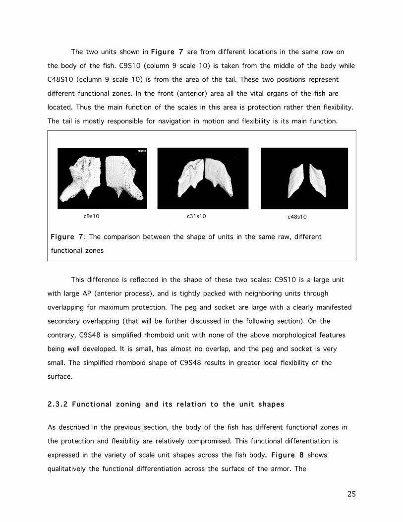
The two units shown in F igure 7 are from different locations in the same row on
the body of the fish. C9S10 (column 9 scale 10) is taken from the middle of the body while
C48S10 (column 9 scale 10) is from the area of the tail. These two positions represent
different functional zones. In the front (anterior) area all the vital organs of the fish are
located. Thus the main function of the scales in this area is protection rather then flexibility.
The tail is mostly responsible for navigation in motion and flexibility is its main function.
F igure 7: The comparison between the shape of units in the same raw, different
functional zones
This difference is reflected in the shape of these two scales: C9S10 is a large unit
with large AP (anterior process), and is tightly packed with neighboring units through
overlapping for maximum protection. The peg and socket are large with a clearly manifested
secondary overlapping (that will be further discussed in the following section). On the
contrary, C9S48 is simplified rhomboid unit with none of the above morphological features
being well developed. It is small, has almost no overlap, and the peg and socket is very
small. The simplified rhomboid shape of C9S48 results in greater local flexibility of the
surface.
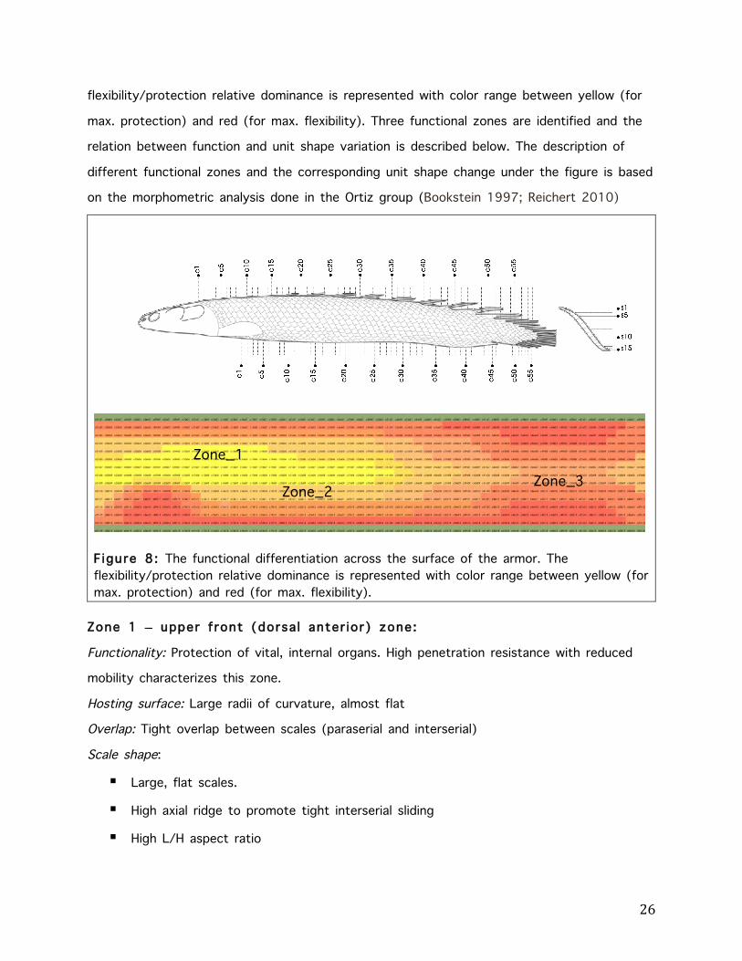
2.3.2 Funct iona l zon ing and its re lat ion to the un it shapes
As described in the previous section, the body of the fish has different functional zones in
the protection and flexibility are relatively compromised. This functional differentiation is
expressed in the variety of scale unit shapes across the fish body. F igure 8 shows
qualitatively the functional differentiation across the surface of the armor. The
c31s10 � c48s10 �c9s10 �
26
flexibility/protection relative dominance is represented with color range between yellow (for
max. protection) and red (for max. flexibility). Three functional zones are identified and the
relation between function and unit shape variation is described below. The description of
different functional zones and the corresponding unit shape change under the figure is based
on the morphometric analysis done in the Ortiz group (Bookstein 1997; Reichert 2010)
F igure 8: The functional differentiation across the surface of the armor. The flexibility/protection relative dominance is represented with color range between yellow (for max. protection) and red (for max. flexibility).
Zone 1 – upper front (dorsa l anter ior) zone:
Functionality: Protection of vital, internal organs. High penetration resistance with reduced
mobility characterizes this zone.
Hosting surface: Large radii of curvature, almost flat
Overlap: Tight overlap between scales (paraserial and interserial)
Scale shape:
§ Large, flat scales.
§ High axial ridge to promote tight interserial sliding
§ High L/H aspect ratio
Zone_1
Zone_2 Zone_3
27
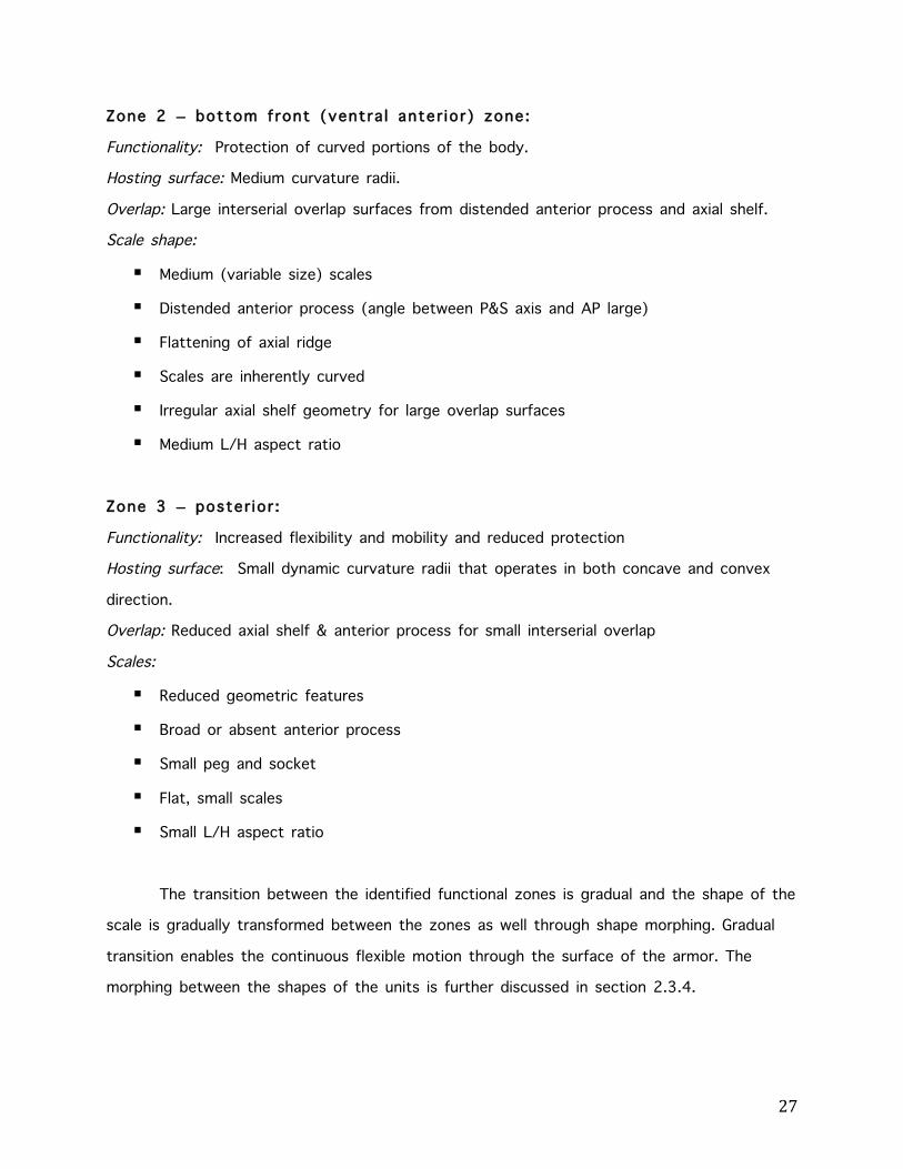
Zone 2 – bottom front (ventra l anter ior) zone:
Functionality: Protection of curved portions of the body.
Hosting surface: Medium curvature radii.
Overlap: Large interserial overlap surfaces from distended anterior process and axial shelf.
Scale shape:
§ Medium (variable size) scales
§ Distended anterior process (angle between P&S axis and AP large)
§ Flattening of axial ridge
§ Scales are inherently curved
§ Irregular axial shelf geometry for large overlap surfaces
§ Medium L/H aspect ratio
Zone 3 – poster ior :
Functionality: Increased flexibility and mobility and reduced protection
Hosting surface: Small dynamic curvature radii that operates in both concave and convex
direction.
Overlap: Reduced axial shelf & anterior process for small interserial overlap
Scales:
§ Reduced geometric features
§ Broad or absent anterior process
§ Small peg and socket
§ Flat, small scales
§ Small L/H aspect ratio
The transition between the identified functional zones is gradual and the shape of the
scale is gradually transformed between the zones as well through shape morphing. Gradual
transition enables the continuous flexible motion through the surface of the armor. The
morphing between the shapes of the units is further discussed in section 2.3.4.
28
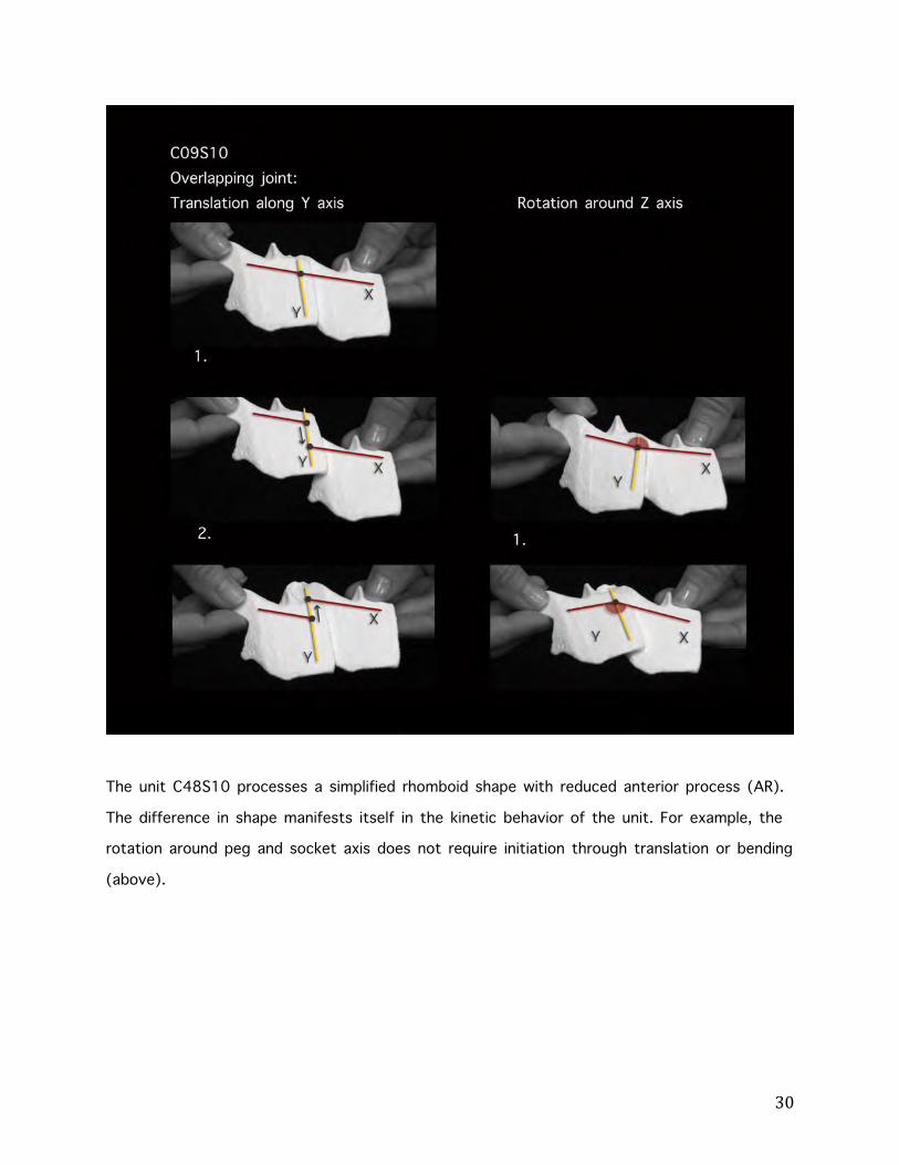
2.3.3 Kinet ic descr ipt ion of jo ints
F igure 9 demonstrates the difference in kinetic behavior of two units from two
functional zones. C09S10 (column 9 scale 10) is taken from the middle of the body while
C48S10 (column 9 scale 10) is from the area of the tail. These two positions represent
different functional zones. In the front (anterior) area all the vital organ of the fish are
located. Thus the main function of the scales in this area is protection rather then flexibility.
The tail is mostly responsible for navigation in motion and the flexibility is it’s main function.
The difference in function manifests itself in the unit shapes, as discussed in section 2.3.1,
but more importantly in the kinetic behavior of the flexible connections: the peg and socket
and the overlapping. Figure 9 demonstrates the compound motions of C09S10. In a tightly
packed mode, the relative motion between units is highly restricted by convoluted
morphological features. But as translation along peg and socket or bending occur, the
allowable ranges of motion increase (F igure 9).

29
30
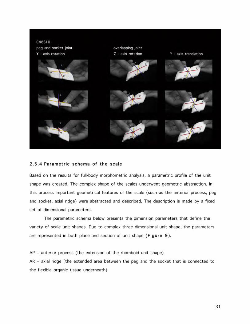
The unit C48S10 processes a simplified rhomboid shape with reduced anterior process (AR).
The difference in shape manifests itself in the kinetic behavior of the unit. For example, the
rotation around peg and socket axis does not require initiation through translation or bending
(above).
31
2.3.4 Parametr ic schema of the sca le Based on the results for full-body morphometric analysis, a parametric profile of the unit
shape was created. The complex shape of the scales underwent geometric abstraction. In
this process important geometrical features of the scale (such as the anterior process, peg
and socket, axial ridge) were abstracted and described. The description is made by a fixed
set of dimensional parameters.
The parametric schema below presents the dimension parameters that define the
variety of scale unit shapes. Due to complex three dimensional unit shape, the parameters
are represented in both plane and section of unit shape (F igure 9).
AP – anterior process (the extension of the rhomboid unit shape)
AR – axial ridge (the extended area between the peg and the socket that is connected to
the flexible organic tissue underneath)
32
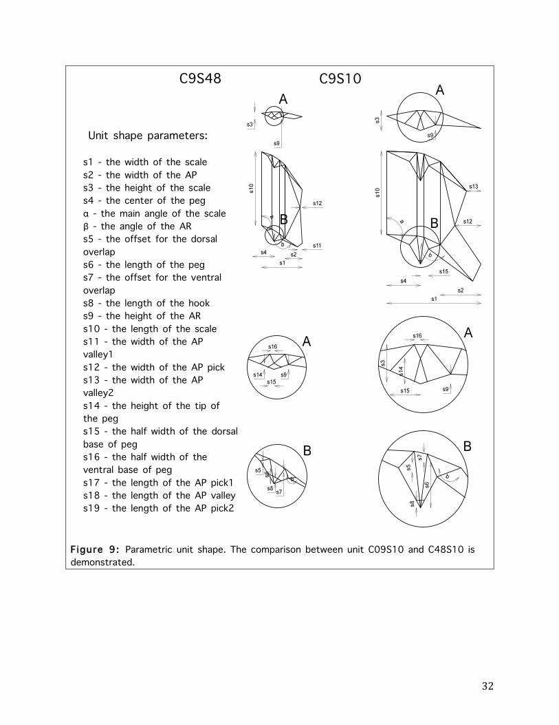
F igure 9: Parametric unit shape. The comparison between unit C09S10 and C48S10 is demonstrated.
Unit shape parameters: s1 - the width of the scale s2 - the width of the AP s3 - the height of the scale s4 - the center of the peg α - the main angle of the scale β - the angle of the AR s5 - the offset for the dorsal overlap s6 - the length of the peg s7 - the offset for the ventral overlap s8 - the length of the hook s9 - the height of the AR s10 - the length of the scale s11 - the width of the AP valley1 s12 - the width of the AP pick s13 - the width of the AP valley2 s14 - the height of the tip of the peg s15 - the half width of the dorsal base of peg s16 - the half width of the ventral base of peg s17 - the length of the AP pick1 s18 - the length of the AP valley s19 - the length of the AP pick2
C9S48 C9S10
33
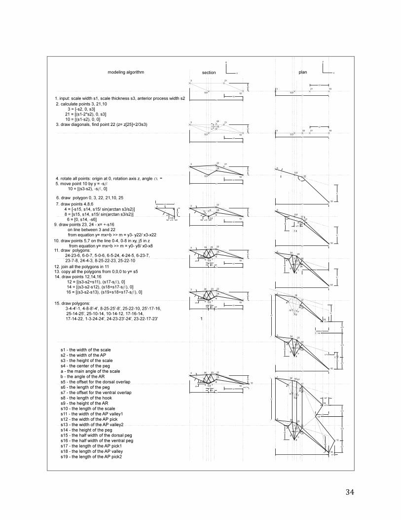
2.3.5 Generat ive model ing a lgor i thm
After the description of the unit shape in a parametric schema, a modeling algorithm was
developed. This algorithm can generate the entire range of biological scale shape variation by
the fixed set of dimension parameters listed in the previous section (F igure 10).
Steps 1-10 in the modeling procedure generate the contact surface of the peg and socket
joint. In the next steps the upper and bottom surfaces are completed with multi-polygon
enclosure.
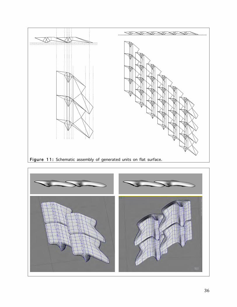
F igure 11 demonstrates the homogeneous assembly of generated units on a flat
surface. Two type of connections -- peg and socket and overlapping – guide the assembly.
In F igure 12 the modeled unit is shown after the surface geometry is converted to mesh
and the shape is smoothed using MeshSmooth algorithm. The modeling software used is
Autodesk® 3ds Max® Design software.
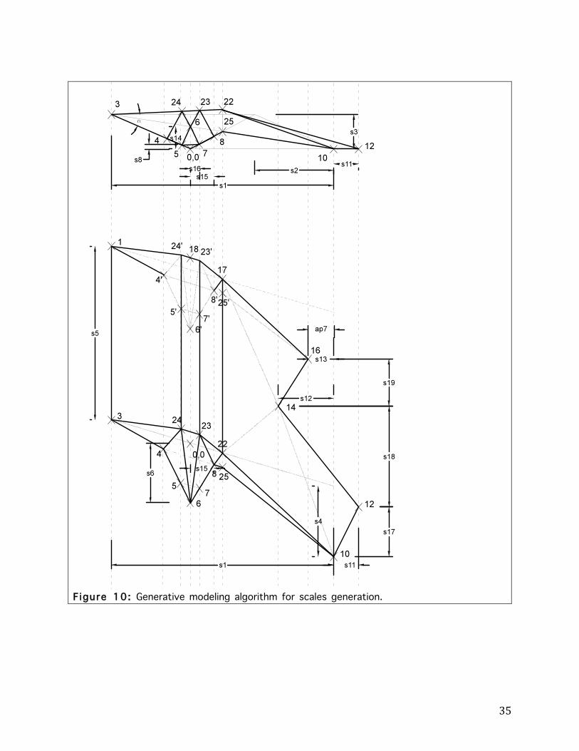
The basic principle of this modeling procedure is to define the 3d space for the unit
through the most basic geometric entities: the points. The procedure locates points in the
3d space in relation to one another. The lines on the figure are shown for the clarity of
presentation. The points are located one in relation to the other based on the input of 19
dimension parameters that are described in the previous section. Once all the points are
located, the shape is enclosed by polygons to generate a 3d shape of the unit. Alternatively,
this cloud of point can serve as a 3d scaffold for properties distribution. The complex unit
shape is a space for material distribution. As discussed in the introduction, the geometry is
only half of the story in the design of Polypterus armor. Once the geometrical principles are
parameterized, the focus of the project will shift on the material properties distribution as
will be further discussed in the conclusions to this project.
34
35
F igure 10: Generative modeling algorithm for scales generation.
36
F igure 11: Schematic assembly of generated units on flat surface.
37
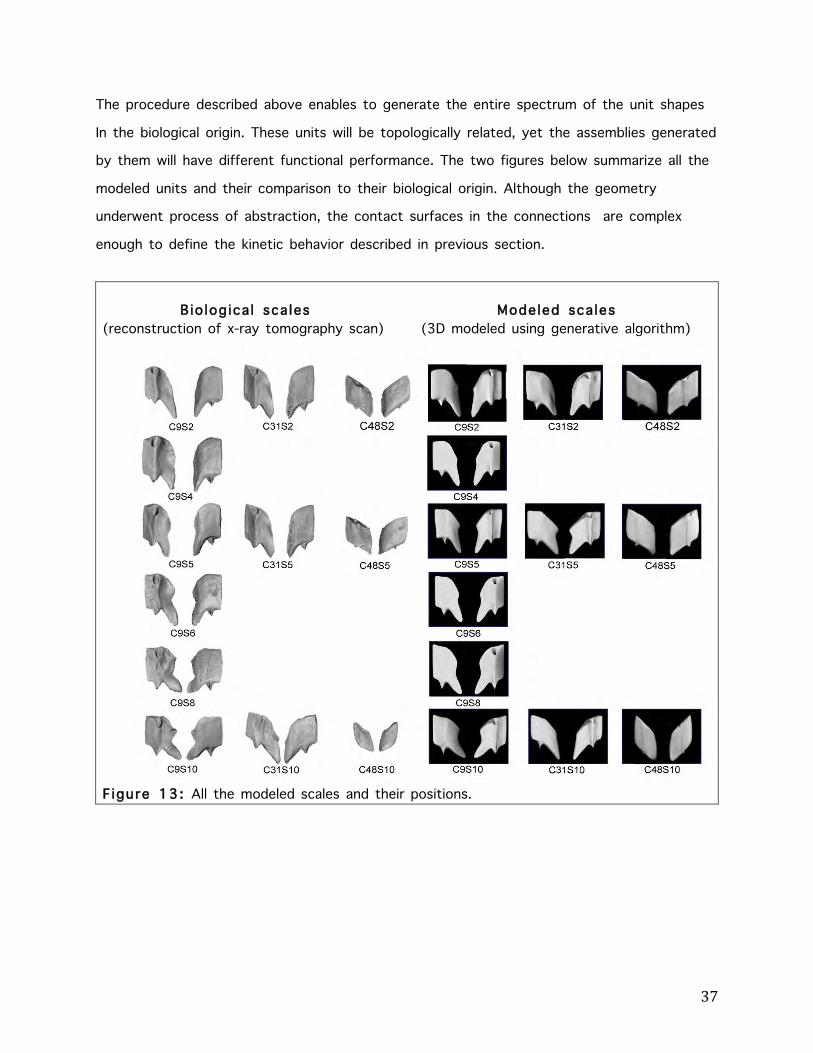
The procedure described above enables to generate the entire spectrum of the unit shapes
In the biological origin. These units will be topologically related, yet the assemblies generated
by them will have different functional performance. The two figures below summarize all the
modeled units and their comparison to their biological origin. Although the geometry
underwent process of abstraction, the contact surfaces in the connections are complex
enough to define the kinetic behavior described in previous section.
B io log ica l sca les Modeled sca les (reconstruction of x-ray tomography scan) (3D modeled using generative algorithm)
F igure 13: All the modeled scales and their positions.
38
39
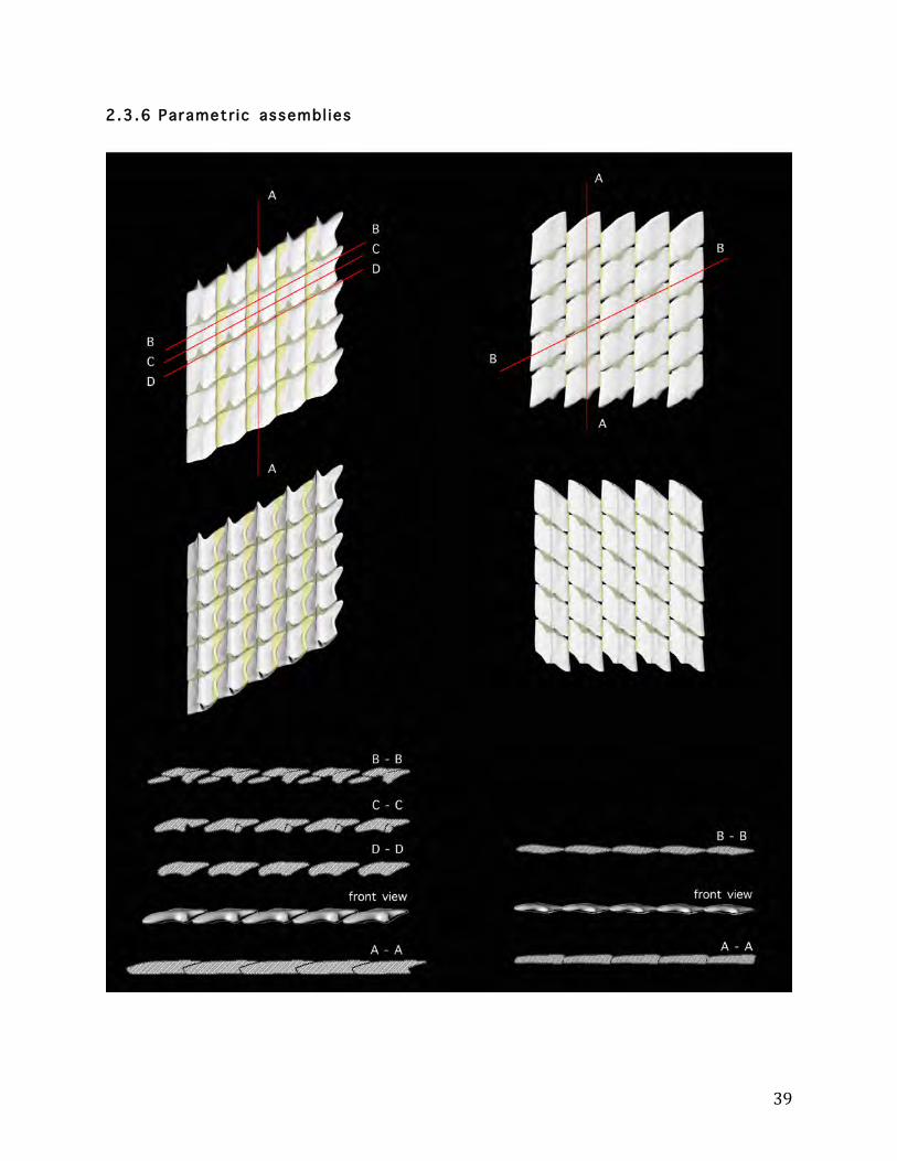
2.3.6 Parametr ic assembl ies

40
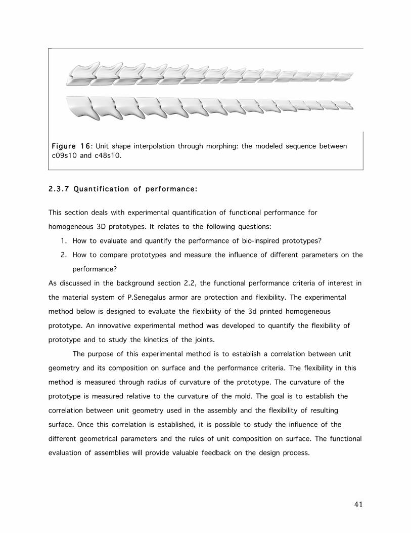
F igure 16 shows a representative parametric model of units across a row of scales
spanning the length of the biological exoskeleton. Two scales were chosen as the start and
end point of the model: C9S10 from the anterior region of the fish with high protective
function, and C48S10 from the tail region with high flexibility. Parametric gradation between
the two shapes generates a sequence of scales for the creation of a heterogeneous armor
assembly. Connections between neighboring units are defined by unit shape, and thus scale
assembly information is encoded into the modeled unit. This modeled assembly is the first
step towards the creation of surfaces with tailorable local performance.
c09s10&
c31s10& c48s10&
c48s10&
c9s10&
41
F igure 16: Unit shape interpolation through morphing: the modeled sequence between c09s10 and c48s10.
2.3.7 Quant i f icat ion of performance:
This section deals with experimental quantification of functional performance for
homogeneous 3D prototypes. It relates to the following questions:
1. How to evaluate and quantify the performance of bio-inspired prototypes?
2. How to compare prototypes and measure the influence of different parameters on the
performance?
As discussed in the background section 2.2, the functional performance criteria of interest in
the material system of P.Senegalus armor are protection and flexibility. The experimental
method below is designed to evaluate the flexibility of the 3d printed homogeneous
prototype. An innovative experimental method was developed to quantify the flexibility of
prototype and to study the kinetics of the joints.
The purpose of this experimental method is to establish a correlation between unit
geometry and its composition on surface and the performance criteria. The flexibility in this
method is measured through radius of curvature of the prototype. The curvature of the
prototype is measured relative to the curvature of the mold. The goal is to establish the
correlation between unit geometry used in the assembly and the flexibility of resulting
surface. Once this correlation is established, it is possible to study the influence of the
different geometrical parameters and the rules of unit composition on surface. The functional
evaluation of assemblies will provide valuable feedback on the design process.
42
In a next stage of design, different geometries of units will be composed on one
surface. The composition will be done according to local surface geometry and local
functional requirements. The overall goal is to develop design system for design of
protective articulated surfaces. These surfaces will have local tailorable flexibility and
protection according to functional requirements and accommodate surfaces with arbitrary
curvature.
Rod- Ind icator method (developed in collaboration with Y.Li and J.Song)
Flexible armor prototypes of homogeneous unit assemblies were 3D printed to study
fundamental morphometric principles, biomechanical mobility mechanisms, and the interaction
between material and morphometric design. A novel experimental technique, called the “rod-
indicator method,” was designed to measure the local flexibility and mechanical anisotropy of
homogeneous assemblies.
Two types of experiments were performed to characterize the anisotropic mechanical
behavior of the homogeneous prototype:
1. The global curvature analysis as function of the orientation of the prototype on mold.
2. The quantification of the local relative motion of adjacent scales as function of the
orientation of the prototype on mold.
For the global curvature analysis, variation in unit shape was introduced and the flexibility
of prototypes was quantified and compared using the rode indicator method. In addition, the
space in peg-and-socket joint was modified and measurements were made on the prototype
with no scales as a reference for these experiments.
43
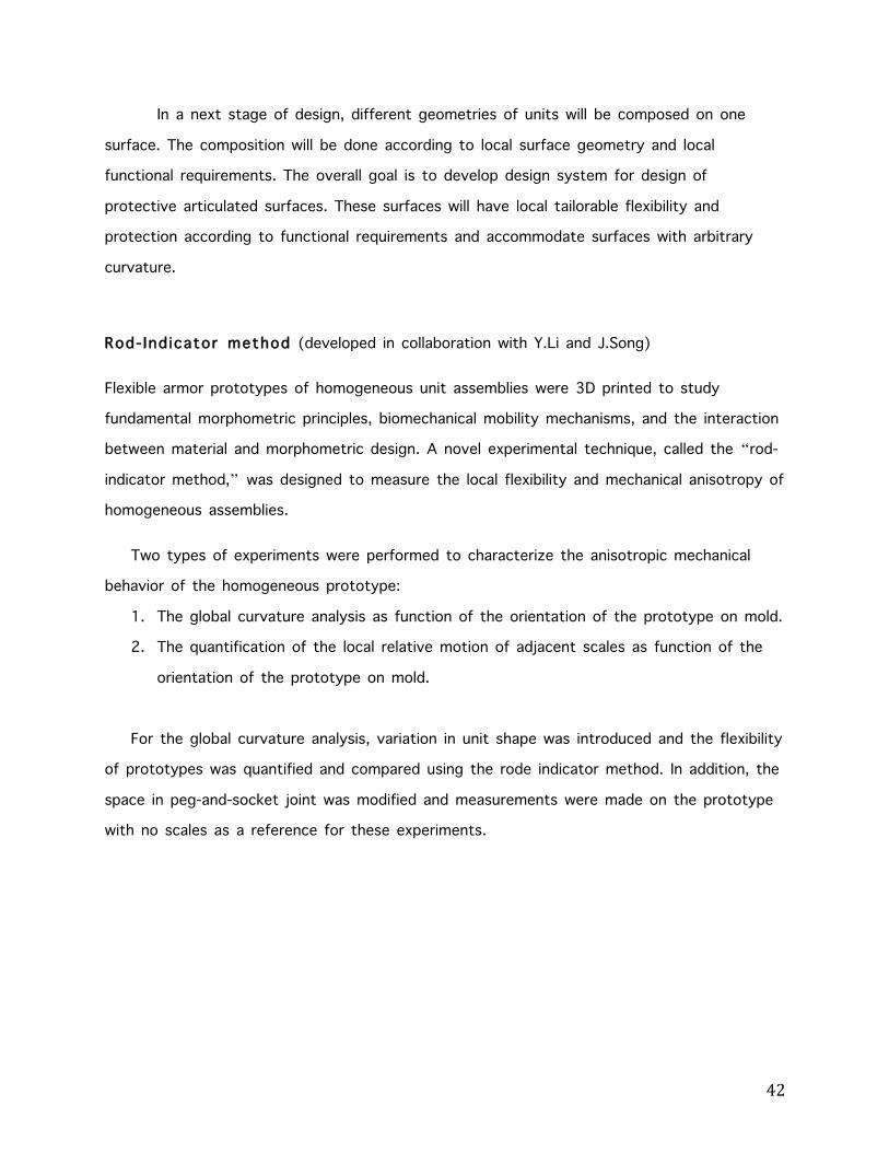
F igure 17: Mold design and fabrication and experimental set up: (a) fabrication of curved mold on vacuum forming machine (b,c) the mold (d) experimental set up
1. The g loba l curvature ana lys is as funct ion of the or ientat ion of the
prototype on mold (Θ) .
Experiment: The curved mold that was fabricated using vacuum forming fabrication method
(F igure 17a). The R/w ratio of 4 between the mold curvature radius (R) and the scale
unit length (w) was used to best demonstrate the anisotropic mechanical behavior of the
prototype. The homogeneous multi-material prototype fabricated as described in Section X
was placed on the mold while the line overlapping is along the zero curvature line of the
mold (Θ=0). The prototype was rotated 15 degrees at a time and the position of the
normal rods was registered and used to measure the curvature radius of the prototype for
each angle (Θ). F igure X shows the relation between the curvature radius of the prototype
(Rt) and the curvature radius of the mold (R) as function of the orientation (Θ).
Results: Mechanical properties are relatively consistent parallel to the rigid axis; perpendicular
to the rigid axis, the prototype exhibits a radius of curvature that rapidly increases with 30-
camera
Prototype on curved mold
A B. C.
D.
44
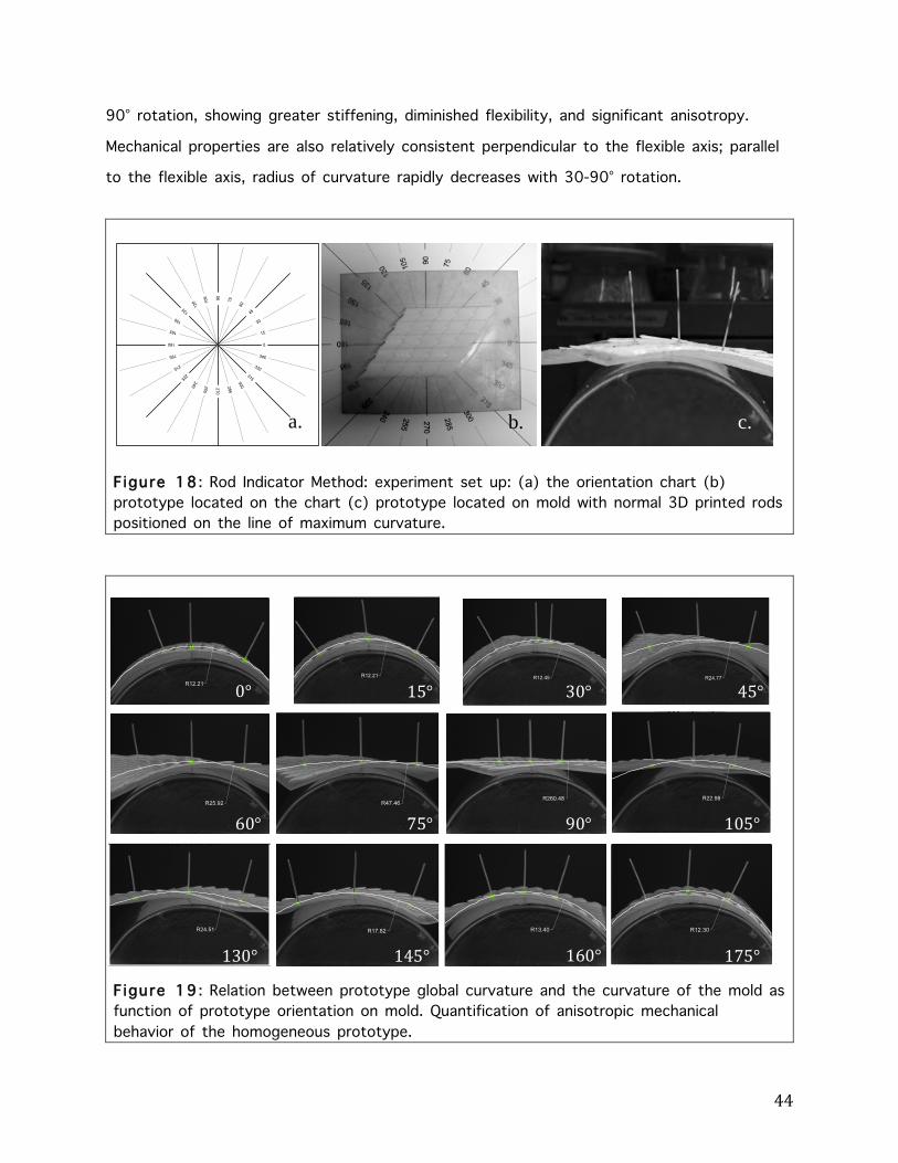
90° rotation, showing greater stiffening, diminished flexibility, and significant anisotropy.
Mechanical properties are also relatively consistent perpendicular to the flexible axis; parallel
to the flexible axis, radius of curvature rapidly decreases with 30-90° rotation.
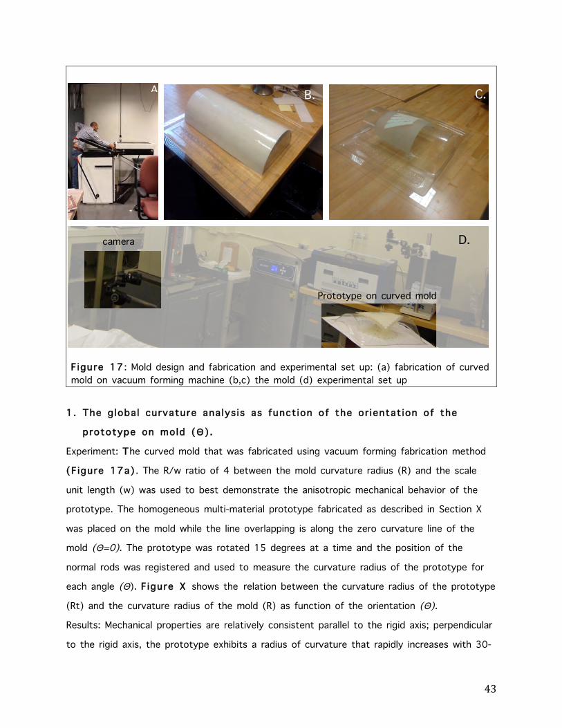
F igure 18: Rod Indicator Method: experiment set up: (a) the orientation chart (b) prototype located on the chart (c) prototype located on mold with normal 3D printed rods positioned on the line of maximum curvature.
F igure 19: Relation between prototype global curvature and the curvature of the mold as function of prototype orientation on mold. Quantification of anisotropic mechanical behavior of the homogeneous prototype.
0° 15° 30° 45°
60° 75° 90° 105°
130° 145° 160° 175°
a. b. c.
45
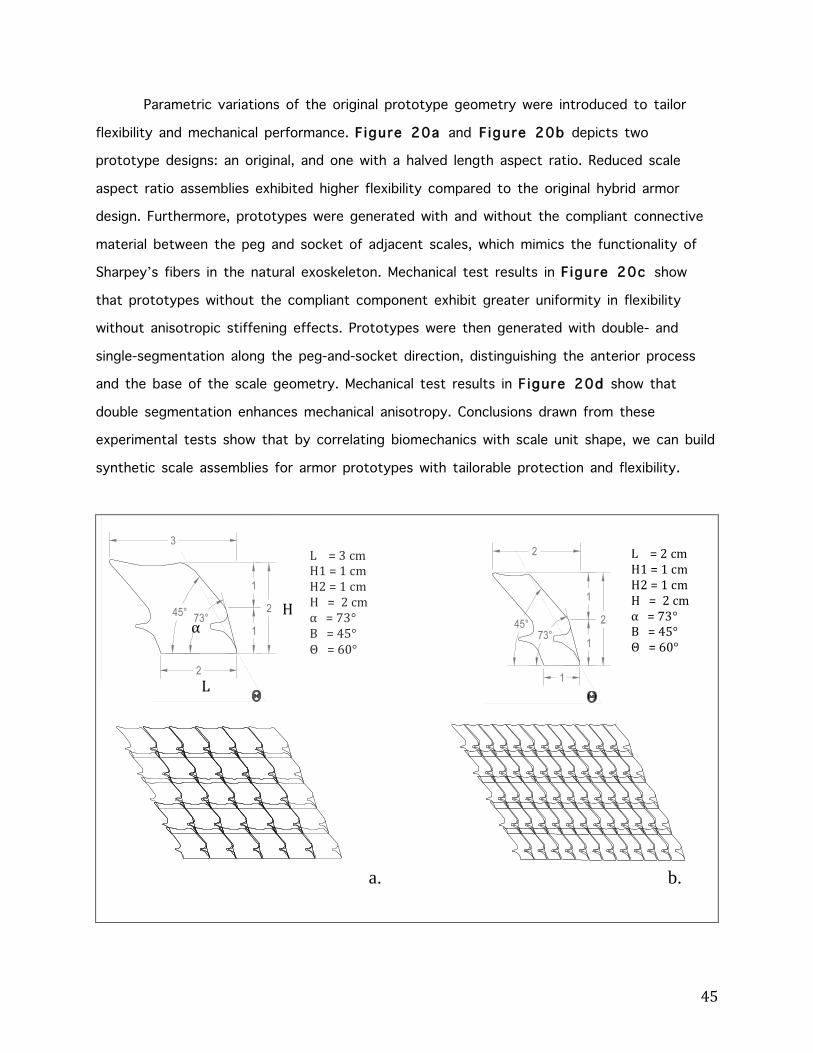
Parametric variations of the original prototype geometry were introduced to tailor
flexibility and mechanical performance. F igure 20a and F igure 20b depicts two
prototype designs: an original, and one with a halved length aspect ratio. Reduced scale
aspect ratio assemblies exhibited higher flexibility compared to the original hybrid armor
design. Furthermore, prototypes were generated with and without the compliant connective
material between the peg and socket of adjacent scales, which mimics the functionality of
Sharpey’s fibers in the natural exoskeleton. Mechanical test results in F igure 20c show
that prototypes without the compliant component exhibit greater uniformity in flexibility
without anisotropic stiffening effects. Prototypes were then generated with double- and
single-segmentation along the peg-and-socket direction, distinguishing the anterior process
and the base of the scale geometry. Mechanical test results in F igure 20d show that
double segmentation enhances mechanical anisotropy. Conclusions drawn from these
experimental tests show that by correlating biomechanics with scale unit shape, we can build
synthetic scale assemblies for armor prototypes with tailorable protection and flexibility.
L = 2 cm H1 = 1 cm H2 = 1 cm H = 2 cm α = 73° Β = 45° Θ = 60°
L = 3 cm H1 = 1 cm H2 = 1 cm H = 2 cm α = 73° Β = 45° Θ = 60°
L
H α
a. b.
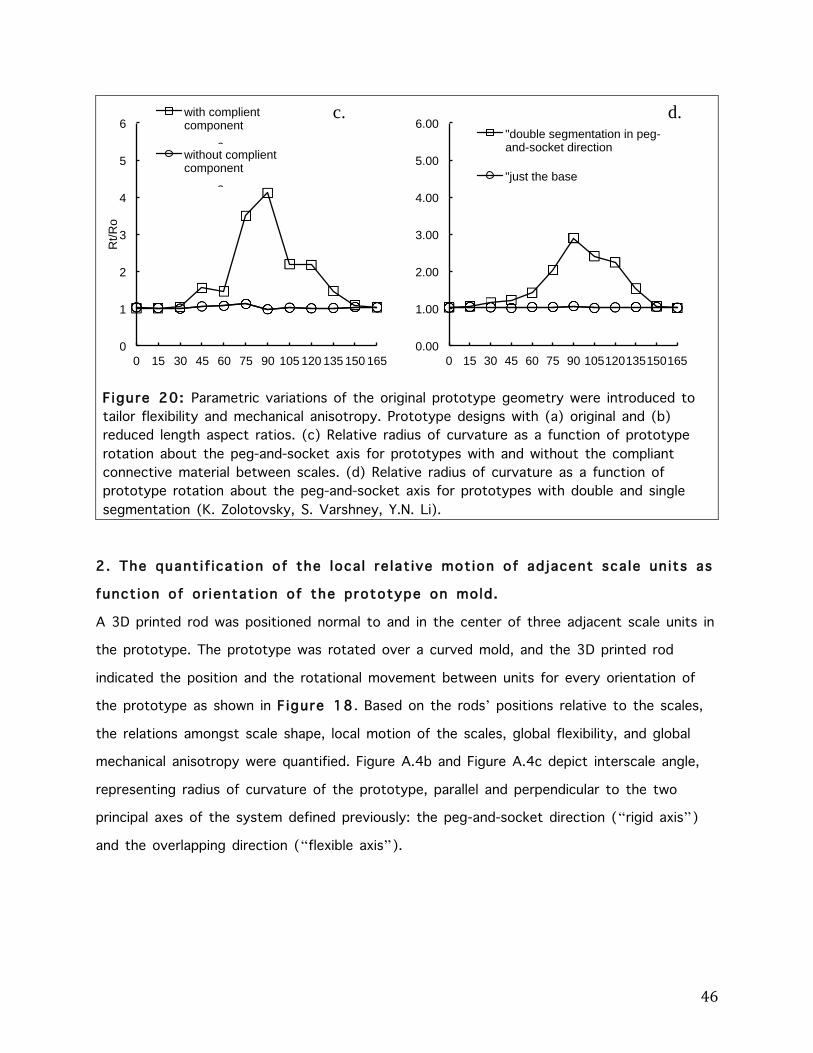
46
F igure 20: Parametric variations of the original prototype geometry were introduced to tailor flexibility and mechanical anisotropy. Prototype designs with (a) original and (b) reduced length aspect ratios. (c) Relative radius of curvature as a function of prototype rotation about the peg-and-socket axis for prototypes with and without the compliant connective material between scales. (d) Relative radius of curvature as a function of prototype rotation about the peg-and-socket axis for prototypes with double and single segmentation (K. Zolotovsky, S. Varshney, Y.N. Li).
2. The quant i f icat ion of the loca l re lat ive mot ion of adjacent sca le un its as
funct ion of or ientat ion of the prototype on mold.
A 3D printed rod was positioned normal to and in the center of three adjacent scale units in
the prototype. The prototype was rotated over a curved mold, and the 3D printed rod
indicated the position and the rotational movement between units for every orientation of
the prototype as shown in F igure 18. Based on the rods’ positions relative to the scales,
the relations amongst scale shape, local motion of the scales, global flexibility, and global
mechanical anisotropy were quantified. Figure A.4b and Figure A.4c depict interscale angle,
representing radius of curvature of the prototype, parallel and perpendicular to the two
principal axes of the system defined previously: the peg-and-socket direction (“rigid axis”)
and the overlapping direction (“flexible axis”).
0
1
2
3
4
5
6
0 15 30 45 60 75 90 105 120 135 150 165
Rt/R
o with complient component
without complient component
a
a
0.00
1.00
2.00
3.00
4.00
5.00
6.00
0 15 30 45 60 75 90 105 120 135 150 165
"double segmentation in peg-and-socket direction
"just the base
c. d.
47
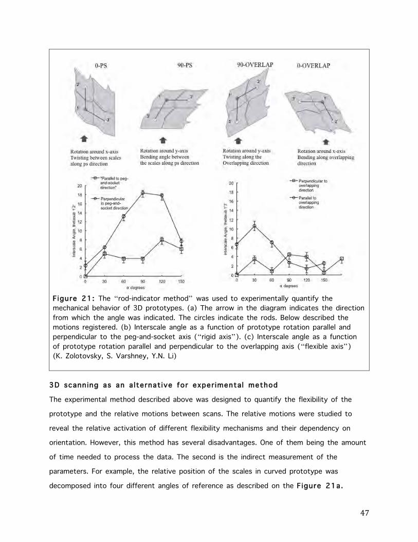
F igure 21: The “rod-indicator method” was used to experimentally quantify the mechanical behavior of 3D prototypes. (a) The arrow in the diagram indicates the direction from which the angle was indicated. The circles indicate the rods. Below described the motions registered. (b) Interscale angle as a function of prototype rotation parallel and perpendicular to the peg-and-socket axis (“rigid axis”). (c) Interscale angle as a function of prototype rotation parallel and perpendicular to the overlapping axis (“flexible axis”) (K. Zolotovsky, S. Varshney, Y.N. Li)
3D scann ing as an a lternat ive for exper imenta l method
The experimental method described above was designed to quantify the flexibility of the
prototype and the relative motions between scans. The relative motions were studied to
reveal the relative activation of different flexibility mechanisms and their dependency on
orientation. However, this method has several disadvantages. One of them being the amount
of time needed to process the data. The second is the indirect measurement of the
parameters. For example, the relative position of the scales in curved prototype was
decomposed into four different angles of reference as described on the F igure 21a.
48
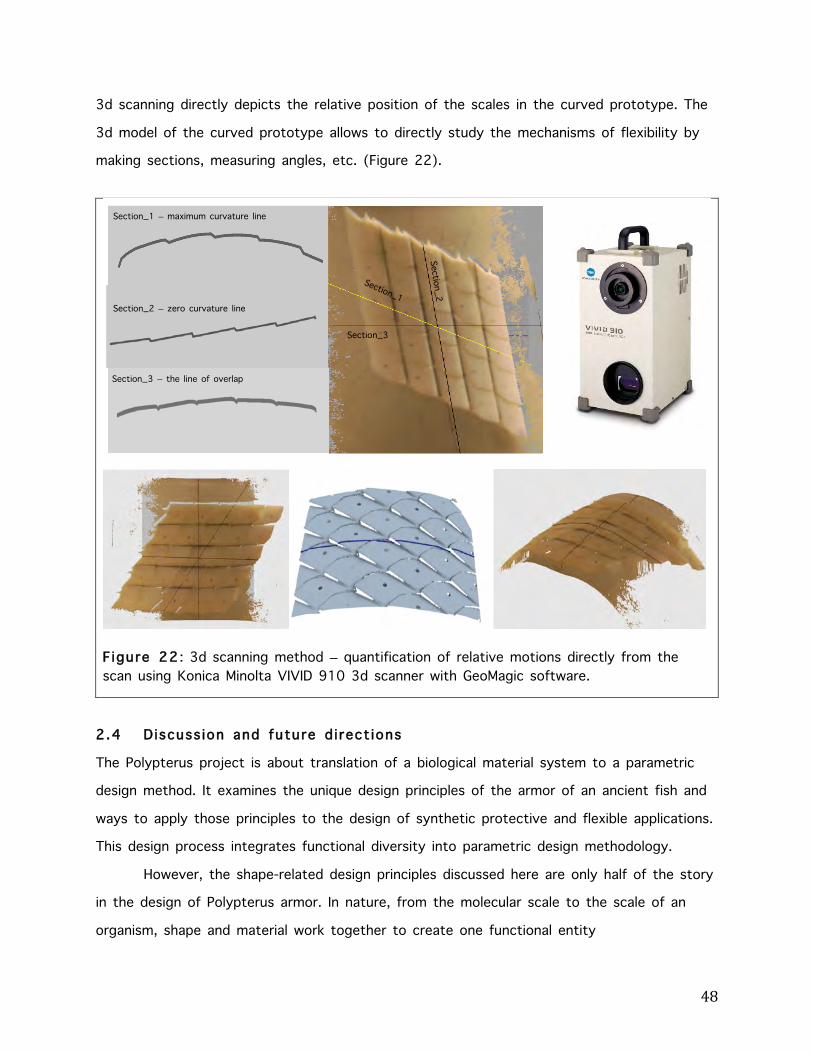
3d scanning directly depicts the relative position of the scales in the curved prototype. The
3d model of the curved prototype allows to directly study the mechanisms of flexibility by
making sections, measuring angles, etc. (Figure 22).
F igure 22: 3d scanning method – quantification of relative motions directly from the scan using Konica Minolta VIVID 910 3d scanner with GeoMagic software.
2.4 Discuss ion and future d i rect ions
The Polypterus project is about translation of a biological material system to a parametric
design method. It examines the unique design principles of the armor of an ancient fish and
ways to apply those principles to the design of synthetic protective and flexible applications.
This design process integrates functional diversity into parametric design methodology.
However, the shape-related design principles discussed here are only half of the story
in the design of Polypterus armor. In nature, from the molecular scale to the scale of an
organism, shape and material work together to create one functional entity
Section_2�
Section_2 – zero curvature line�
Section_1 – maximum curvature line�
Section_3 – the line of overlap��
Section_3�
49
(organism/structure). By understanding the material principles in design of natural systems, it
is possible to develop new design methodologies that combine material-based and geometry-
based strategies. Previous work has been done on the analysis of material strategies (8).
Synthetic prototypes that mimic granular internal material structure of the scales were
previously design and fabricated (9). As a future direction for project development, I would
like to integrate previously described and tested material composition strategies with the
parametric system described here. This approach can be viewed as distribution of material
properties in the parametric shape space to support function (9,10).
Another goal that will guide future development of the project is to step further from
the biological system of origin toward the new design application. The focus in the work
described here was on individual units and simplified surfaces with homogeneous unit
assemblies. The key development in the future work on this project will be the view of the
armor system as a whole. The armor operates as one functional entity, and it is connected
to the spine of the fish that guides the locomotion. The middle lines on the body of the fish
(the dorsal and ventral lines) are the main structural lines of the armor system (see Chapter
1). These lines provide structural and functional framework to the armor. The spine of the
fish is connected to the dorsal and ventral lines of specialized units, “lines of rigidity”, that
provide a functional framework to the armor. The units between these lines are connected
through non-structural joints -- peg-and-socket joints and overlapping. This hierarchy of lines
characterizes the fish armor as one functional entity. In the transition to the new application,
it is important to clearly define the new functional framework and its relation to the
functional framework of the biological origin.
The work on the P.Senegalus was performed in the Ortiz group toward the
development of articulated body armor for soldiers. In this relation, the new functional
domain for the segmented, flexible and protective armor is the human body. The strategy
for the transition is yet to be developed. It will require description of the human armor
through the similar terms of lines of connections with anisotropic ranges of allowable
motions.
In general, the work described here presents part of a step-by-step process of
transition from the functional domain of biological origin to the new functional domain (such
as human body). The parameterization process described here allows generation of unit
50
shape according to a fixed set of dimension parameters. The kinetic behavior of this unit in
assembly is determined by the contact surfaces of its morphometric features (peg and
socket, anterior process). The composition of the unit on homogeneous prototype and the
experimental evaluation of the flexibility of this prototype are also developed. This last step
establishes the link between two types of information: the geometrical information of unit
shape and the functional information on the performance of this unit’s assembly.
The transition to a new functional domain requires development of new functional
framework for armor assembly. In the Polypterus armor system, the functional framework
consists of lines of connections between units. The generation of these lines for the human
body will be guided by two main factors: the geometry of the hosting surface and the
kinetic diagram of allowable motions. Once the functional frame of lines of connections will
be created and characterized by allowable ranges of motion, it will provide the input
parameters for unit shape generation and design. The overall composition of units on surface
according to kinetic diagram of allowable motions is subject for further research.
To summarize, there are two main directions for future project development. The first
is the integration of material-based strategies in the parametric design system. The second
is the development of heterogeneous assemblies according to kinetic diagram of allowable
motion on arbitrary curved surfaces. Both open the possibility of fascinating research in bio-
inspired design.

51
The Xyl inus project
The Xylinus project explores novel modes of design and fabrication by combining digital tools
and technologies with living biological systems. This study describes an innovative process of
fabrication by controlling the material production of cellulose by bacteria (biofabrication). The
larger goal behind the project is to use synthetic biology methods to control the biological
system (the bacteria) genetically. In biofabrication, the properties of material and its spatial
organization are guided by two main factors. The first is inherent material properties that
can be designed on the genetic level. The design on genetic level is presented here
conceptually and will be further developed in the future. The second factor is the influence
of growth conditions. The experiments described here aim to direct the spatial organization
of cellulose through control of the growth environment. The goal of this research was to
understand how to design material structures and their performance through the control of
environmental conditions of growth. This approach can be called “design by environment”.
There are three main motivations for this work. The first relates to fabrication
with bacterial cellulose as an alternative to wood construction. As we look for a way to
reduce carbon dioxide emissions in the atmosphere, there is growing interest in the use of
native biopolymers as an alternative for paper and wood (Brown 2004). Nature has provided
us with rich alternative sources for cellulose, the main constituent of wood. The most
common bacteria on earth, Acetobactor Xylinus, produces cellulose as its basic life function.
Although extensive research has been done in the fields of biology, material science, and
chemistry, on cellulose structure, performance, and its use for medical applications, little
attention has been paid to the potential use of cellulose as a construction material. The
experimental work presented here is a first step toward scaling up fabrication with bacterial
cellulose for architecture and design purposes.
The second motivation for this project is the opportunity working with biological
systems provides. Instead of working with the material for construction as inert matter,
there is an opportunity to develop a fabrication method in which there is a constant dialog
between the environment and the design artifact. In the experiments described here, the
52
object is grown and formed under the influence of the environment and in constant dialog
with it.
The third motivation is recent developments of CAD-based additive fabrication
technology. Additive fabrication changes the way we work with matter. The idea of an
object being created bottom-up according to external instruction is very appealing as a
model for fabrication with native biopolymers. In section 3.2.4 the idea of biological 3d
printer will be further discussed.
The work presented here and the idea for the experimentation with biopolymers
and the cellulose-producing bacteria was developed in collaboration with Dr. Jon Babb from
the Weiss Lab of Synthetic Biology, MIT and Sergio Araya, Professor at Design Lab,
Universidad Adolfo Ibanez, Chile. The materials of this chapter were included in our
publication with Sergi Araya “Living Architecture. Micro Performances of Bio Fabrication” for
Ecaade 2012.
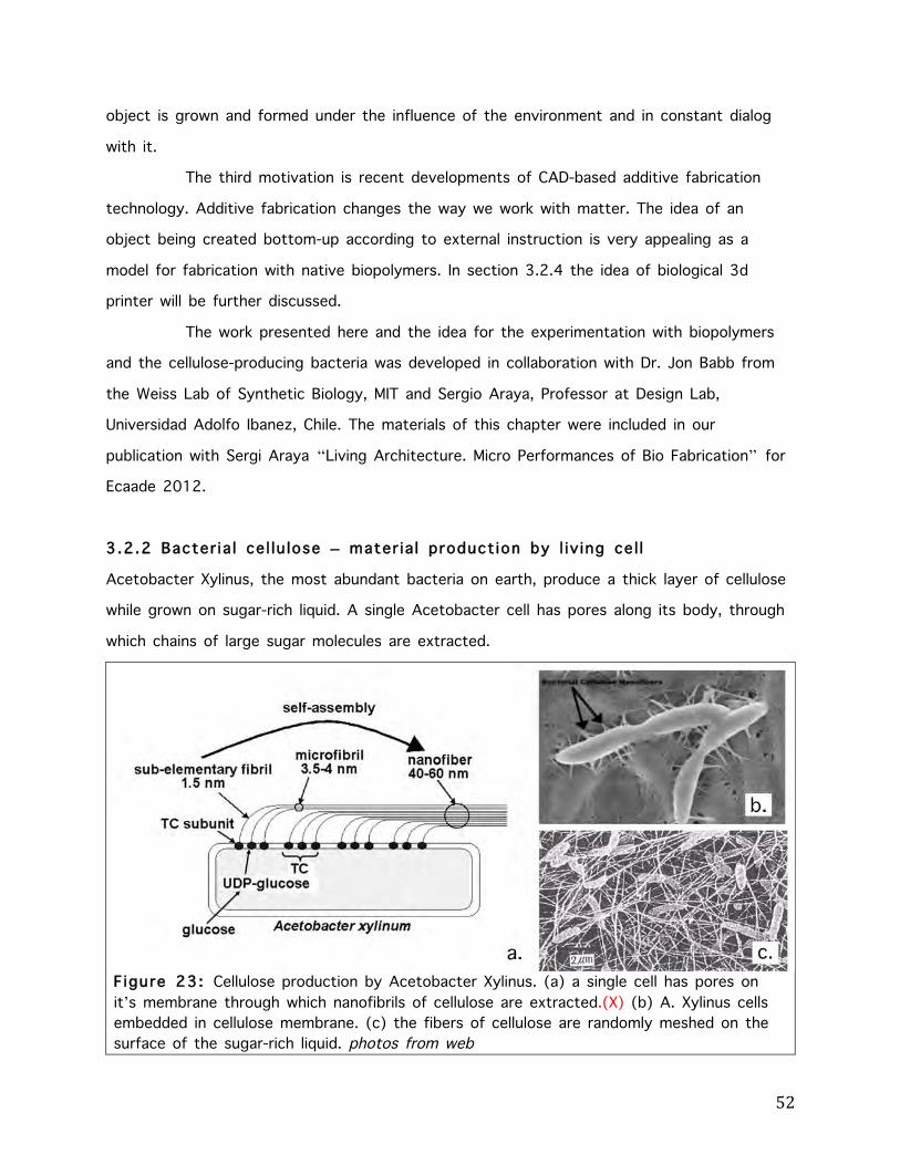
3.2.2 Bacter ia l ce l lu lose – mater ia l product ion by l iv ing ce l l
Acetobacter Xylinus, the most abundant bacteria on earth, produce a thick layer of cellulose
while grown on sugar-rich liquid. A single Acetobacter cell has pores along its body, through
which chains of large sugar molecules are extracted.
F igure 23: Cellulose production by Acetobacter Xylinus. (a) a single cell has pores on it’s membrane through which nanofibrils of cellulose are extracted.(X) (b) A. Xylinus cells embedded in cellulose membrane. (c) the fibers of cellulose are randomly meshed on the surface of the sugar-rich liquid. photos from web

53
A cell spins sugar chains together to create sub-microscopic fibers. These fibers then mesh
together to form a membrane on the surface of a liquid. When dried, this membrane
becomes a sheet of thick, paper-like material. The process is relatively simple and fast and
many researchers in the field have outlined the potential to control the growth of cellulose
into any desired form (Bielecki et al. 1996; Brown 1975; Brown 2004). Yet, most of the
research in the field concentrates on medical applications of bacterial cellulose, such as a
scaffold for tissue engineering.
F igure 24: Growth process of microbial cellulose. (a) Large culture set up: 1 – growth medium added to the tank, 2 – heating pad, 3 – time-lapsed camera. The white formation is the cellulose membrane growing on a surface. (b) The cellulose membrane taken out of the liquid
3.2.3 Synthet ic B io logy – genet ic des ign of mater ia l propert ies
By manipulating and reassembling bacterial genetic material, it is possible to alter material
properties of the produced cellulose and its spatial organization. This is possible by applying
genetic engineering techniques. The collaboration with the Weiss Lab for Synthetic Biology
allows feasibility of research in this direction. Below are two suggestions on ways to
introduce control over bacterial cellulose growth on genetic level. One suggestion is purely
instrumental. Most of the experience in genetic manipulations that researchers have gained
up to now is in bacteria called E.Coli. It has much higher growth rate than cellulose-producing
Acetobacter Xylinum and it can be easily manipulated. It would be worth trying to isolate the
genetic complex responsible for cellulose production and to transform it to E.Coli. This will
enable higher material production rates and more control over material properties produced.
Xylinum project independent study project, spring 2011 supervisor: Prof.Takehiko Nagakura
The most common bacteria on earth,Acetobactor Xylinum, produce cellulose as itsbasic life function. The cellulose forms a thickmembrane on a liquid surface.
Acetobacter Xylinumbacterial cellulose “micro-industry”
Acetobacter Xylinumthe tank static systemset up -- 04.24.2011
05.13.2011 initiating new layer of pellicle
------------------------ HS medium
------------ time-lapsed camera ------- heating pad
d-glucose 10gr peptone 2.5gr east extract 2.5gr sodium phosphate 1.35gr citric acid 0.75gr water 500ml
Bacteria cells spinning cellulose fibers, that mesh together to create a thick layer of bacterial cellulose onthe surface - microscopic images
a.
Xylinum project independent study project, spring 2011 supervisor: Prof.Takehiko Nagakura
The most common bacteria on earth,Acetobactor Xylinum, produce cellulose as itsbasic life function. The cellulose forms a thickmembrane on a liquid surface.
Acetobacter Xylinumbacterial cellulose “micro-industry”
Acetobacter Xylinumthe tank static systemset up -- 04.24.2011
05.13.2011 initiating new layer of pellicle
------------------------ HS medium
------------ time-lapsed camera ------- heating pad
d-glucose 10gr peptone 2.5gr east extract 2.5gr sodium phosphate 1.35gr citric acid 0.75gr water 500ml
Bacteria cells spinning cellulose fibers, that mesh together to create a thick layer of bacterial cellulose onthe surface - microscopic images
b. a.
1
2 3

54
F igure 25: Heterogeneous material distribution in microbial cellulose structure.
3.2.4 Bio 3d pr inter – genet ica l ly modif ied addit ive/subtract ive
mater ia l process
Another suggestion is to attach a genetic switch to the cellulose bacterial complex.
Genetic switch is an existing genetic mechanism in bacteria that has two configurations. In
its activated configuration, it will induce the function of specific gene or complex of genes,
in this case the complex responsible for production of bacterial cellulose. In its deactivated
state, such production will be suppressed. This switch, in turn, can be activated or
deactivated by external stimuli, such as UV light. By introducing a genetic switch to bacterial
complex, it will be possible to activate the production of cellulose in specific areas on the
surface of the liquid by lighting them. Similarly to 3D printing technique, this principle will
allow the configuration of each layer according to software analysis by applying UV light to
it. This will make possible to build a biological 3D printer that will grow the object layer-by-
layer according to the data received from a computational 3D model. There are many
55
possible directions for genetic manipulations, and this exploration will be much more workable
once the cellulose complex will be transformed to E.Coli.
As mentioned in the introduction to this chapter, design of material properties on genetic
level is only presented here conceptually. This discussion is mainly concerned with the
physical control over material growth and its spatial distribution. The following sections
describe and discuss the experimental work produced by myself and Sergio Araya in the
Weiss Lab of Synthetic Biology, MIT. Section 3.3 describes materials and methods used for
the experiments. Section 3.4 presents the physical set up for material growth as a
parametric system. In this system, controlled changes in the growth environment orchestrate
spatial organization of material. Section 3.5 discusses the experiments performed and the
observations made. This chapter concludes with the summery of observations and discussion
of future directions.
3.3 Mater ia ls and methods:
Bacteria strain
Gram negative cellulose-producing bacteria Acetobacter Xylinum. We used bacterial strain
ATCC number 10245 (http://www.atcc.org/). The original strain was received from Prof.
David Kaplan from TERC (Tissue Engineering Resource Center), from the Department of
Biomedical Engineering at Tufts University.
Growth medium*
In our experiments we used Schramm–Hestrin (SH) medium containing 2.0% D-glucose, 0.5%
yeast extract, 0.5% peptone, 0.51% di-sodium hydrogenphosphate heptahydrate, 0.115%
citric acid (Hestrin & Schramm, 1954).
*medium – nutrition-rich liquid for bacteria growth

56
Optical density (OD)
We used OD measurements to estimate and compare bacterial growth at the initial overnight
cultures. Samples of 1ml were measured and compared to pure HS media used as a blank.
Average values of 0.1 were read at 600 nm indicated overnight bacterial growth.
Static culture growth
In static mode of growth the bacteria was added to a measured volume of HS medium and
placed in the incubator/ heated with heating pad to achieve optimal temperature for bacteria
growth (+27°C according to literature).
Agitated culture growth
In agitated mode of growth, the culture was fixed on a vibrating platform and constantly
shaken. This created a continuous oxygen access to the bacteria in the liquid medium and
accelerated growth. The agitated cultures were placed in incubator (+30°C).
Molding in vivo*
*In vivo – “within the living” (from Latin)- experimentation using the whole, living organism.
Molds with varying surface textures and texture resolutions were designed, modeled in
Rhinoceros and 3D printed in Objet Convex. The mold was fixed in a 100ml cylindrical glass
container. 50ml HS medium was added to the containers. The cellulose membrane was pre-
grown on a Petri dish and introduced to the containers. After the membrane was stabilized
and the growth stopped, we took the mold with the membrane out and left it to dry in
room temperature overnight. Then de-molding was performed using scalpel to gently peel the
membrane of the mold.
Molding in vitro*
*In vitro – “within the glass” (from Latin)– in controlled environment, using isolated
components of living/dead organism.
In the in vivo molding experiment we used a static culture growth in an aquarium tank of
twenty-five gallon. Six liter of HS medium was added to the tank and seven days old pre-
grown small cellulose membranes from six Petri plates were introduced. The thermostat-

57
controlled heating pad kept temperature to the optimum of +27°C and time-lapsed web
camera was programmed to three times a day shots. The constant volume of medium was
kept by adding fresh medium every 3-4 days. When the membrane achieved its maximum
dimensions of 120*220*8 mm and stabilized, it was removed from the tank, rinsed with tap
water and placed on the CNC-milled wooden mold. Petroleum Jelly was applied on the mold
for easier de-molding. It was left to dry for four days in room temperature.
Lyophilization
We used lyophilization to evaporate the water and yet preserve the spatial configuration of
cellulose fibers. The samples were removed from the medium still on the 3D printed mold
and gradually frozen: first at (-20°C) for overnight, then at
(-80°C). The frozen samples were transferred to Labconco lyophilizer for several days and
kept frozen at (-20°C) before de-molding attempt.
3.4 Parametr ic condit ions:
The fabrication process of material structures and their performance are directly affected by
the environmental conditions. The central aspect of designing with living systems is carefully
planning and controlling the external environmental conditions in order to induce the behavior
of the organism. This is crucial both in the initial set up and over the growth time. Below we
list some of the main conditions affecting material production processes in our experiments:
Nutrients optimization:
The main input for the material production process is sugar (glucose) in the medium and
oxygen. We are currently working on replacing the sugar in HS medium with sugar-rich waste
from food industries. This will enable us to create a sustainable design process when the
waste from one industry production is used as basis resource for another, but also because
it would drop costs down allowing us to scale up the process towards construction material
standards.

58
Oxygen supply:
The bacteria need both oxygen and nutrients for material production. In static culture, the
cellulose membrane will be produced in the interface between the air and the liquid (medium
containing the nutrients). By designing the mode of oxygen supply both in the initial set up
and over time, we can control the spatial organization of the material and it’s material
properties.
Temperature, pH:
The temperature and pH affect the rate of material production. The optimal conditions
based on the literature are pH=6.0 and temperature of +27°C. Nonetheless, it has also been
proven that different strains of bacteria are productive at different environmental conditions,
aspect that is being investigated in order to fine tune the optimal pH and temperature
conditions to grow/reproduce the bacterial colony, then to induce or stop material
production, effectively orchestrating when and how cellulose structures are to be produced.
Timeline:
As growth of material structure is a gradual process, the conditions of the material
production can be orchestrated over time. For example, by adding medium in measured time
periods, the layering of cellulose structure with loose connections between the layers can be
achieved, thus creating a panel of cellulose with varying material properties.
3.5 Observat ions
3.5.1 Observat ion_1: Inher i t versus emergent mater ia l propert ies
Methods: agitated culture growth
For this stage of initial growth we used 25 falcon tubes, each containing 3ml of HS medium
inoculated with Xylinus. After an overnight growth in agitated culture in 30°C incubator, we
observed variety of formations in the tubes (F igure 26). Some of the cellulose formations
had a loose cloudy structure, other tubes presented dense granulated structures or even a
combination of both. Same variation in shape was later observed in larger volume growth.

59
F igure 26: Spontaneous variation in the initial growth.
Discussion:
Although the conditions of the 25 tubes were exactly the same, the variation probably
resulted from spontaneous mutation during bacterial growth. While working with living
matter, there is a constant dialog between the designer and the artifice, involving decision-
making, adaptation and alternation at each stage. For example, out of 25 different
formations we can choose those with material properties that suit best our design intentions
for further growth. The designer is able to influence and direct the process of co-adaptation
between the grown object and its environment.
3.5.2 Observat ion_2: Respons ive des ign system, Regrowth.
Methods: static culture growth
HS medium (10ml) were added on 10 Petri dishes and placed in 30°C incubator for static
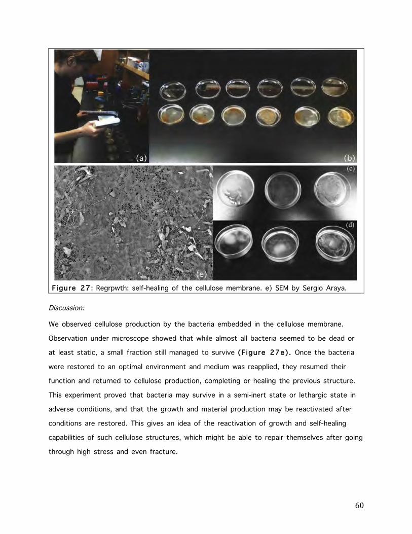
growth (F igure 27a). The next day the cellulose membrane was formed on the surface.
The medium evaporated due to large surface/volume ratio. More medium was added to the
plates and the samples were returned to the incubator. After 7 days the samples were taken
out. Due to the continuous evaporation and temperature the membranes were almost
completely dry, some of them even became dry and brittle and ended up cracking up
(F igure 27b,d) . They were then removed from the incubator, were inoculated with new
medium and returned to the 30°C incubator. The next day we observed renewed growth in
the samples, and new cellulose growing over and between the cracked edges of the
previously dry membrane (F igure 27e).
60
F igure 27: Regrpwth: self-healing of the cellulose membrane. e) SEM by Sergio Araya.
Discussion:
We observed cellulose production by the bacteria embedded in the cellulose membrane.
Observation under microscope showed that while almost all bacteria seemed to be dead or
at least static, a small fraction still managed to survive (F igure 27e). Once the bacteria
were restored to an optimal environment and medium was reapplied, they resumed their
function and returned to cellulose production, completing or healing the previous structure.
This experiment proved that bacteria may survive in a semi-inert state or lethargic state in
adverse conditions, and that the growth and material production may be reactivated after
conditions are restored. This gives an idea of the reactivation of growth and self-healing
capabilities of such cellulose structures, which might be able to repair themselves after going
through high stress and even fracture.
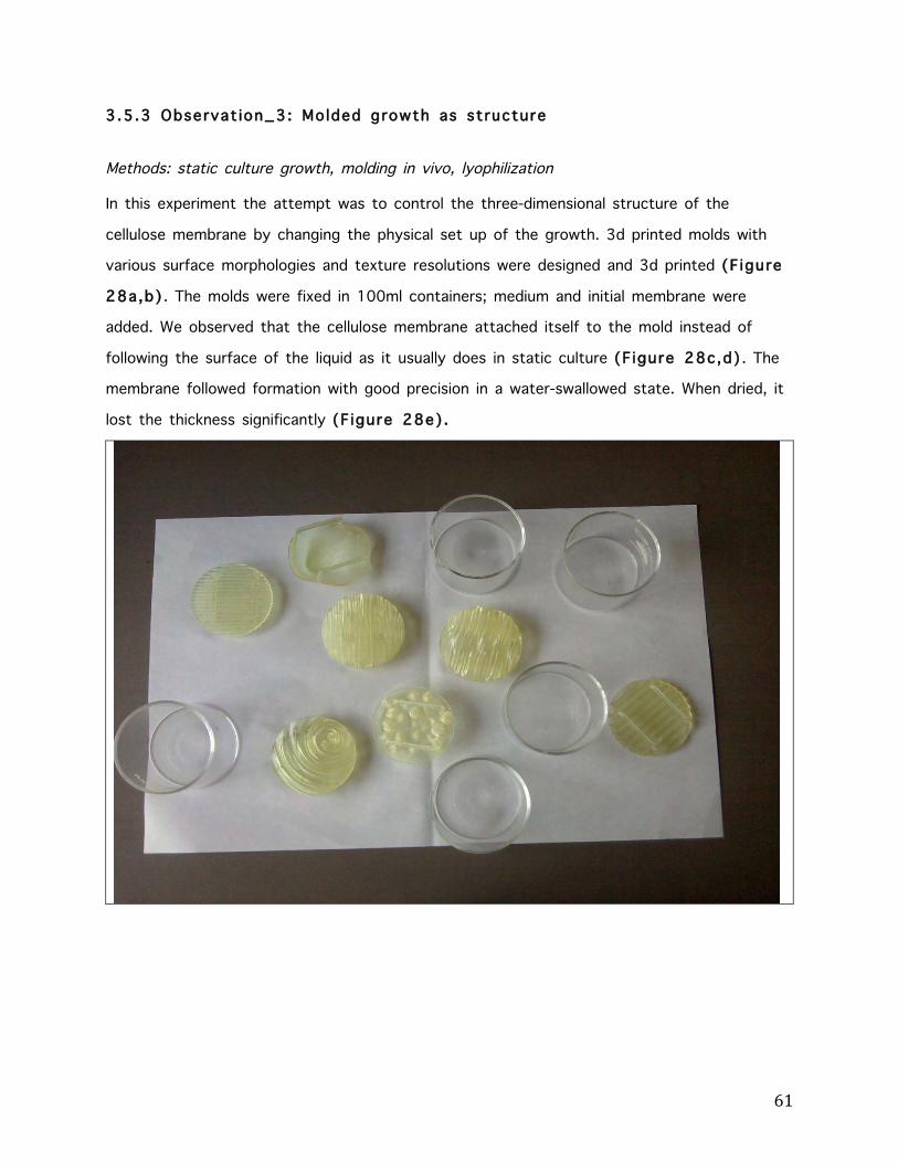
61
3.5.3 Observat ion_3: Molded growth as structure
Methods: static culture growth, molding in vivo, lyophilization
In this experiment the attempt was to control the three-dimensional structure of the
cellulose membrane by changing the physical set up of the growth. 3d printed molds with
various surface morphologies and texture resolutions were designed and 3d printed (F igure
28a,b) . The molds were fixed in 100ml containers; medium and initial membrane were
added. We observed that the cellulose membrane attached itself to the mold instead of
following the surface of the liquid as it usually does in static culture (F igure 28c,d) . The
membrane followed formation with good precision in a water-swallowed state. When dried, it
lost the thickness significantly (F igure 28e).
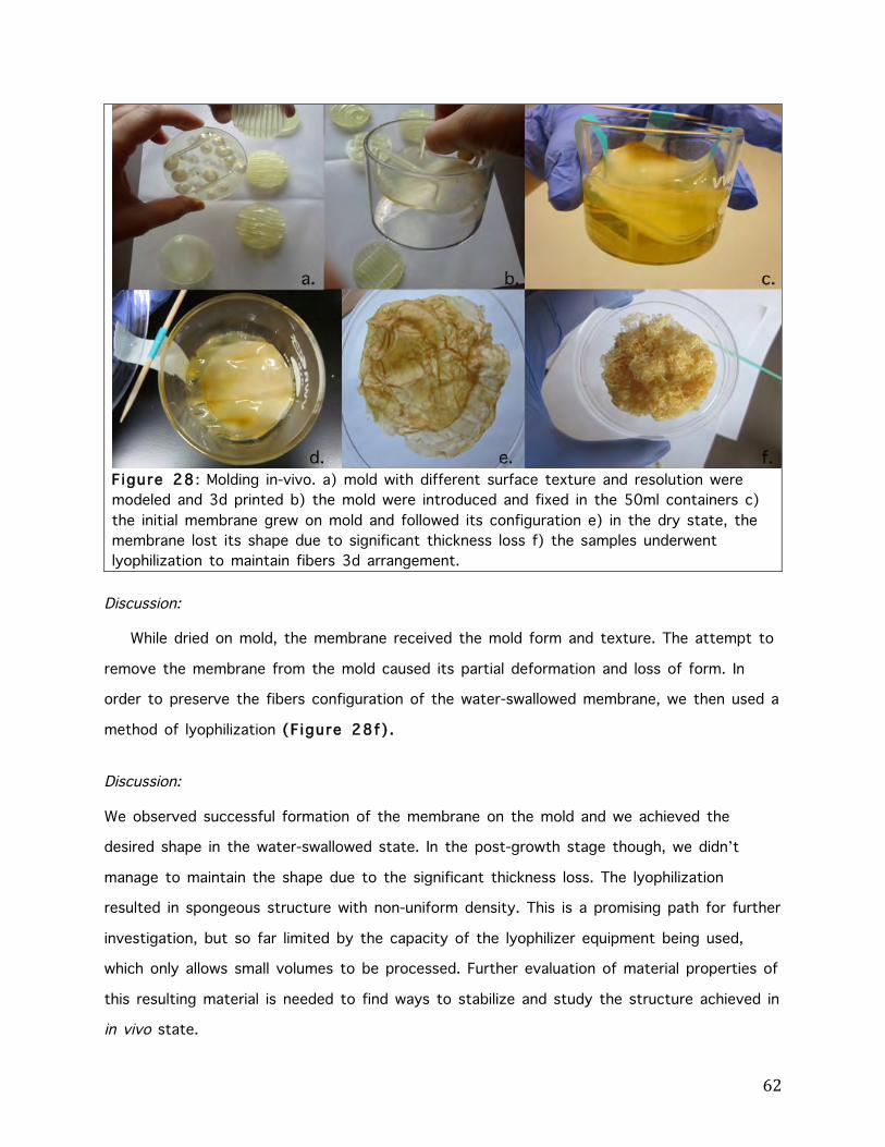
62
F igure 28: Molding in-vivo. a) mold with different surface texture and resolution were modeled and 3d printed b) the mold were introduced and fixed in the 50ml containers c) the initial membrane grew on mold and followed its configuration e) in the dry state, the membrane lost its shape due to significant thickness loss f) the samples underwent lyophilization to maintain fibers 3d arrangement.
Discussion:
While dried on mold, the membrane received the mold form and texture. The attempt to
remove the membrane from the mold caused its partial deformation and loss of form. In
order to preserve the fibers configuration of the water-swallowed membrane, we then used a
method of lyophilization (F igure 28f) .
Discussion:
We observed successful formation of the membrane on the mold and we achieved the
desired shape in the water-swallowed state. In the post-growth stage though, we didn’t
manage to maintain the shape due to the significant thickness loss. The lyophilization
resulted in spongeous structure with non-uniform density. This is a promising path for further
investigation, but so far limited by the capacity of the lyophilizer equipment being used,
which only allows small volumes to be processed. Further evaluation of material properties of
this resulting material is needed to find ways to stabilize and study the structure achieved in
in vivo state.
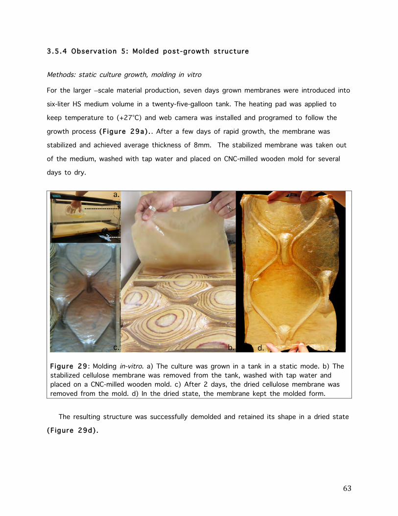
63
3.5.4 Observat ion 5: Molded post-growth structure
Methods: static culture growth, molding in vitro
For the larger –scale material production, seven days grown membranes were introduced into
six-liter HS medium volume in a twenty-five-galloon tank. The heating pad was applied to
keep temperature to (+27°C) and web camera was installed and programed to follow the
growth process (F igure 29a). . After a few days of rapid growth, the membrane was
stabilized and achieved average thickness of 8mm. The stabilized membrane was taken out
of the medium, washed with tap water and placed on CNC-milled wooden mold for several
days to dry.
F igure 29: Molding in-vitro. a) The culture was grown in a tank in a static mode. b) The stabilized cellulose membrane was removed from the tank, washed with tap water and placed on a CNC-milled wooden mold. c) After 2 days, the dried cellulose membrane was removed from the mold. d) In the dried state, the membrane kept the molded form.
The resulting structure was successfully demolded and retained its shape in a dried state
(F igure 29d).
64
Discussion:
Larger scale in vitro molding experiment was more successful then the in vivo in maintaining
the structure achieved. Even the finest texture of the mold was visible on the resulting
shape.
3.5.5 Observat ion 6: B io log ica l 3D pr inter
Methods: static culture growth
In the large-scale in vitro experiment described above, we observed the following material
production mode: once pre-grown initiation membrane is introduced to the medium, it enters
the stage of rapid growth. The nutrients and oxygen availability are the main limiting factors
in this process and at certain thickness the cellulose is stabilized and no additional growth is
observed. New layer can be initiated at this point by adding fresh medium on top of the old
one. When fresh medium was added on top of the stabilized membrane, new membrane was
initiated on the new surface level, while sending loose connecting fibrous formations to the
old layer below (F igure 30).

65
F igure 30 by Serg io Araya: Schematic diagram of layering structure of cellulose membrane growth. Once the first membrane stabilized, medium addition will initiate a new membrane on top. The new membrane will be connected to the old one by loose fibrous cellulose formation.
Discussion:
This layering technique gave us the idea of biological 3D printer – if the surface of the liquid
was constantly moved by adding fresh medium, constant material production might be
achieved. The layering mode can enable sequential build – up of an object.
If we learn enough about how to control the configuration of each layer, we can build up
(grow) a material formation (an object) into any desired shape. Conceptually, we can
suggest two possible ways to control the configuration of each layer:
Genetically: using genetic engineering methods it is possible to control the production of
cellulose. It is possible to engineer Xylinum cells to produce enzyme cellulaze that degrades

66
the cellulose. By spatially distributing cellulose-producing and cellulose-degrading bacteria in
each layer, it is possible to build up any desired shape.
Physiologically: it is also possible to combine genetic control with the physiological one.
For example, by attaching UV light-sensitive promoter to the cellulose-producing complex it is
possible to turn the production of cellulose on and off. The bacteria in the areas that
receive UV light will produce cellulose, and those in the dark areas won’t. This way to
control additive versus subtractive mode is through attaching genetic switch to the cellulose
production complex was discussed in introduction of this chapter.
Both of these ways to control cellulose production spatially will require extensive research
and experimentation in collaboration between designers, architects, and synthetic biologists.
3.6 Discuss ion and future d i rect ions
In the experiments presented here, we were able to obtain material production and achieve
some level of control over it. In the large-scale culture, the growth of a twelve by twenty-
two inches cellulose membrane was achieved. The membrane was almost 1cm thick in its
water-swollen condition. The resulting membrane showed significant strength and stability
compared to the membranes grown in smaller containers. Due to the membrane’s large size,
we were able to extract it from the tank culture, shape it on the CNC-milled wooden mold
and de-mold successfully.
The experiments in both larger and smaller scale showed that the growth is highly
dependent on the environmental conditions. The changes of these parameters – temperature,
nutrient-medium (HS), time – resulted in changes in the cellulose structure produced.
Furthermore, by introducing changes in the growth conditions, we were able to initiate
layering of cellulose structures. Separate layers of cellulose were produced by the same
culture, due to managing time intervals of medium addition.
While we have yet to test different extreme environmental parameters for the cultures,
we now know that the bacteria can resist and survive under unfavorable growth conditions.
In our experiment, we observed regrowth after several days of high temperature, shortage in
nutrition and medium evaporation. As soon as medium was added and optimal growth
conditions restored, cellulose production was fully resumed. This observation allows us to
speculate about the capacity of cellulose structures to become self-healing structures. One
67
advantage of such living and performing structure could be local response to stress. Once
stress is applied on cellulose structure and it is due to deformation and failure, the system
can respond with cellulose production and fix the damage. In more general terms, living
structures are able to respond to changes in the environmental conditions over time. The
response can be in rate of material production, the structure of spatial organization of
material, it’s density, etc. In our experiments, we were able to collect initial observation of
these responses.
For the next steps in this research, the characterization of material properties of
cellulose for large-scale fabrication will be experimentally tested and characterized. The
tension-compression tests will be performed and acoustic and thermal properties of microbial
cellulose membrane will be characterized. In addition, the co-use of microbial cellulose with
other materials will be created and tested for performance. Using microbial cellulose as
healing material for wooden structures is one idea in this direction. The ability of microbial
cellulose to grow in adaptive mode and adjust its structure and properties to the existing
environment will be explored.
In parallel to the physical aspects of cellulose research mentioned above, possibilities of
design on the genetic level will be further researched. As suggested in the introduction
section, there are two main initial goals for the design on a genetic level of microbial
cellulose production. First is the transformation of the genetic complex responsible for
cellulose production to E.Coli to induce growth rate and enable genetic manipulation. Second,
is the attachment of a genetic switch to the cellulose-producing complex. This will allow
switching on and off cellulose production by external stimuli such as UV light. Once the two
modes of operation – material production on and off – are enabled, the research will focus
on biological 3D printer development. Of course, the genetic design work will require close
collaboration with synthetic biologists.
In general, design with living matter requires new modes of operation in design and
fabrication. The parametric logic is applied to the environment of growth at both micro
(genetic design) and macro (physical setup of growth). The balance between independent
and dependent variables of the growth environment define the form and properties of the
produced object. This balance is in dynamic state and changes rapidly over time. Any change
in the growth conditions will result in changes of the growth process and the grown object.

68
These changes will reflect back on the environment and so on. The grown object is in
constant feedback loop with its environment. The designer needs to observe and respond to
the process by changing the growth environment parameters. This way, the designer, the
growth environment, and the grown object are in a constant feedback loop of operation and
response.
Design and fabrication with microbial cellulose opens up an exciting opportunity to
develop new way of design and fabrication. The main input for this manufacturing process is
sugar that can be obtained from the wastes of food industries (U.S. Army’s Natick 1974).
Furthermore, microbial cellulose structures can be degraded back to nature after they serve
their function (Beguin and Aubert 1994). The impact of this sustainable fabrication process
can be highly beneficial for the environment and might serve as a competitive alternative to
current manufacturing techniques once developed and established. Instead of processing
natural material and using them in their inert state for fabrication and construction, there is
a possibility of growing environment-responsive, self-healing and biodegradable cellulose
structures. The development of these manufacturing techniques requires interdisciplinary
collaboration in the fields of biology, computer science, engineering and architecture.
Although results of experimentation presented here are partial and incomplete, I believe they
are first steps towards new mode of fabrication with living material-producing biological
systems.
Conclusions
The work presented here is a part of ongoing research and investigation. In the Polypterus
project, the process of transition from analysis to synthesis is the main focus of the
research presented here. This process involves abstraction, parameterization and translation
of geometrical, material, and functional parameters. Discussed here are the parametric
definition of the variety of unit shapes and the correlation between this variation and the
functional performance of anisotropic flexibility of the homogeneous assemblies of units. An
experimental method to quantify the anisotropic flexibility for homogeneous units geometries
is presented.
69
As discussed in the conclusions for the Polypterus project, the experimental
evaluationof prototype anisotropic flexibility establishes the correlation between two types of
data. The first type is geometrical data of unit shape and the second is the functional data
of kinetic performance of the unit assembly. The generative modeling algorithm discussed in
section 2.3.5 generates unit shape according to a set of dimension parameters. The
experimental method presented in section 2.3.7 evaluates the anisotropic flexibility of
homogeneous assembly of this unit. In other words, the input of a fixed set of dimensional
parameters provides an output of functional performance – anisotropic flexibility of an
assembly.
There are two directions for the future development of this research as discussed in
section 2.4. One is the integration of material – based strategies of Polypterus armor to the
design. The other is the formulation of functional framework for armor assembly on new
functional domain. This functional framework will allow heterogeneous assemblies on curved
surfaces according to kinetic diagram of allowable motion. Both directions coexist in the
development of articulated armor for human body that is developed in the Ortiz group.
Bio-inspired design enables designers to approach the functional perfection of design
by nature. This design process involves a careful process of abstraction, adaptation and
translation of natural design principles. Within collaboration between designers and biology-
related science communities, such as biomimetic material science and mechanical engineering,
it is possible to develop new design methodologies. These innovative methodologies can
contribute to a design of new exciting applications, and also to rethinking of the design
process itself.
In the Xylinus project, microbial cellulose opens an exciting opportunity to develop new
ways of fabrication and design. The impact of this sustainable fabrication process can be
highly beneficial for the environment and once developed and established, it might serve as a
competitive alternative to current manufacturing techniques. Instead of processing natural
material and using them in their inert state for fabrication and construction, there is a
possibility of growing environment-responsive, self-healing and biodegradable cellulose
structures. The development of these manufacturing techniques requires interdisciplinary
collaboration in the fields of biology, computer science, engineering and architecture.
70
Bib l iography
Polypterus pro ject : Araya, S., 2011. Performative Architecture. PhD Dissertation, School of Architecture and Planning, Massachusetts Institute of Technology. Arciszewski, T., and Cornell, J., 2006. Bio-inspiration: Learning Creative Design Principia. Intelligent Computing in Engineering and Architecture, 32-53. Bookstein, F. L., 1997. Morphometric Tools for Landmark Data: Geometry and Biology. Rev and Expande. Cambridge University Press, June 28. Brainerd, E. L., 1994. Mechanical design of polypterid fish integument for energy storage during recoil aspiration. Journal of Zoology 232, no. 1: 7-19. = Bruet, B. J. F., 2008. Multiscale structural and mechanical design of mineralized biocomposites. PhD Dissertation, Department of Material Science and Engineering, Massachusetts Institute of Technology. Bruet, B.J. F., Song, J., Boyce, M.C., and Ortiz, C., 2008. Materials design principles of ancient fish armour. Nat Mater 7, no. 9: 748-756. Bunge, M., 1974. Treatise on Basic Philosophy, Vol. I Semantics I: Sense and Reference. Dordrecth-Boston: Reidel Publishing Co. Gemballa, S. and Bartsch, P., 2002. Architecture of the integument in lower teleostomes: functional morphology and evolutionary implications. Journal of Morphology 253, no. 3: 290-309. Ortiz, C. and Boyce, M.C., 2008. MATERIALS SCIENCE: Bioinspired Structural Materials. Science 319, no. 5866 (February 22): 1053-1054. doi:10.1126/science.1154295. Pearson, D. M., 1981. Functional aspects of the integument in polypterid fishes. Zoological Journal of the Linnean Society 72, no. 1: 93-106. Reichert, S., 2010. Reverse Engineering Nature: Design Principles for Flexible Protection Inspired by Ancient Fish Armor of Polypteridae, SMarchS thesis in Department of Architecture, Massachusetts Institute of Technology. Song, J., 2011. Multiscale Materials Design of Natural Exoskeletons: Fish Armor, PhD thesis in Department of Material Science and Engineering, Massachusetts Institute of Technology.

71
Wang, L.F., Song, J.H., Ortiz, C., Boyce, M.C., 2009. Anisotropic design of a multilayered biological exoskeleton. Journal of Materials Research 24, 3477-3494. Wu, L.Q. and Payne, G.f., 2004. Biofabrication: using biological materials and biocatalysts to construct nanostructured assemblies. TRENDS in Biotechnology Vol.22 No.11. Xy l inus pro ject : Araya, S., 2011, Performative Architecture, PhD Dissertation, School of Architecture and Planning, Massachusetts Institute of Technology. Beguin, P., and Aubert, J.P., 1994. The biological degradation of cellulose. FEMS Microbiology Reviews, Wiley Online Library. Bielecki, S., Krystynowicz, A., Turkiewicz M., and Kalinowska, H., 1996. Bacterial Cellulose. Biopolymers. Wiley-Interscience. Brown, R M, Willison, J. H., and Richardson, C.L. 1976. Cellulose biosynthesis in Acetobacter xylinum: visualization of the site of synthesis and direct measurement of the in vivo process. Proceedings of the National Academy of Sciences 73 (12): 4565 -4569. Brown, R. M., 1985. Microbial Synthesis of Cellulose. BIOEXPO 85: 325-335. Microbial Cellulose. Brown, R. M., 2004. Microbial Cellulose: A New Resource for Wood, Paper, Textiles, Food and Specialty Products, Department of Botany, The University of Texas at Austin.
Hwang, J. W, Yang, Y.K., Hwang, J. K. , Pyun, Y. R., and Kim Y. S., 1999. Effects of pH and dissolved oxygen on cellulose production by Acetobacter xylinum BRC5 in agitated culture. Journal of Bioscience and Bioengineering 88 (2): 183-188. Saxena, I., . Lin, F.C., and Brown R.M., 1990. Cloning and sequencing of the cellulose syntahse catalytic subunit gene of Acetobacter Xylinum. Plant Molecular Biology 15: 673-683.
Svenson, A., E. Nicklasson, Harrah, T., Panilaitis, B., and Kaplan, D.L., 2004. Bacterial cellulose as a potential scaffold for tissueengineering of cartilage. Biomaterials (26): 419-431.
Thomas, K. L., 2007. Material Matters: Architecture and Material Practice. 1st ed. Routledge, May 15. U.S. Army’s Natick, 1974. Waste cellulose possible glucose source. Chemical & Engineering News 52 (21) (May 27): 20. doi:10.1021/cen-v052n021.p020.

72