design and evaluation of a wearable skin stretch device
TRANSCRIPT

HAL Id: hal-01935192https://hal.inria.fr/hal-01935192
Submitted on 26 Nov 2018
HAL is a multi-disciplinary open accessarchive for the deposit and dissemination of sci-entific research documents, whether they are pub-lished or not. The documents may come fromteaching and research institutions in France orabroad, or from public or private research centers.
L’archive ouverte pluridisciplinaire HAL, estdestinée au dépôt et à la diffusion de documentsscientifiques de niveau recherche, publiés ou non,émanant des établissements d’enseignement et derecherche français ou étrangers, des laboratoirespublics ou privés.
Design and Evaluation of a Wearable Skin StretchDevice for Haptic Guidance
Francesco Chinello, Claudio Pacchierotti, Joao Bimbo, Nikos Tsagarakis,Domenico Prattichizzo
To cite this version:Francesco Chinello, Claudio Pacchierotti, Joao Bimbo, Nikos Tsagarakis, Domenico Prattichizzo. De-sign and Evaluation of a Wearable Skin Stretch Device for Haptic Guidance. IEEE Robotics andAutomation Letters, IEEE 2018, 3 (1), pp.524 - 531. �10.1109/LRA.2017.2766244�. �hal-01935192�

Design and evaluation of a wearable skin stretch device
for haptic guidance
Francesco Chinello, Claudio Pacchierotti, Member, IEEE, Joao Bimbo, Member, IEEE,
Nikos G. Tsagarakis, Senior Member, IEEE, Domenico Prattichizzo, Fellow, IEEE
Abstract— We present a wearable skin stretch device forthe forearm. It is composed of four cylindrical end effectors,evenly distributed around the user’s forearm. They can generateindependent skin stretch stimuli at the palmar, dorsal, ulnar,and radial sides of the arm. When the four end effectors rotatein the same direction, the wearable device provides cutaneousstimuli about a desired pronation/supination of the forearm.On the other hand, when two opposite end effectors rotate indifferent directions, the cutaneous device provides cutaneousstimuli about a desired translation of the forearm. To evaluatethe effectiveness of our device in providing navigation informa-tion, we carried out two experiments of haptic navigation. Inthe first one, subjects were asked to translate and rotate theforearm toward a target position and orientation, respectively.In the second experiment, subjects were asked to control a6-DoF robotic manipulator to grasp and lift a target object.Haptic feedback provided by our wearable device improvedthe performance of both experiments with respect to providingno haptic feedback. Moreover, it showed similar performancewith respect to sensory substitution via visual feedback, withoutoverloading the visual channel.
I. INTRODUCTION
Haptic devices capable of providing only cutaneous stimuli
have recently gained a great deal of attention in the haptics
and robotics research fields. Cutaneous feedback provides an
effective way to simplify the design of haptic interfaces [1],
[2], and it has been proven to play a key role in enhancing the
performance and effectiveness of telepresence and immersive
systems [3]–[5]. It is also particularly promising for robotic
teleoperation applications, as cutaneous stimuli do not affect
the stability and safety of the control loop [3], [5]–[8], and
navigation applications, as cutaneous stimuli can provide rich
information in an unobtrusive and private way.
Indeed, several researchers have developed and used
cutaneous devices for navigation purposes. Spiers et al. [9]
designed a shape-changing handheld device to provide
pedestrian navigation instructions. The device resembled a
cube with an upper half that rotates and translates with
F. Chinello is with the Dept. Business Development and Technol-ogy at Aarhus University in Herning, Midtjylland, Denmark. E-mail:[email protected]
C. Pacchierotti is with the CNRS at Irisa and Inria Rennes BretagneAtlantique, Rennes, France. E-mail: [email protected].
J. Bimbo, N. G. Tsagarakis, and D. Prattichizzo are with the Dept.Advanced Robotics, Fondazione Istituto Italiano di Tecnologia, Genova,Italy. E-mail: {nikos.tsagarakis, domenico.prattichizzo}@iit.it
D. Prattichizzo is also with the Dept. Information Engineering andMathematics, University of Siena, Siena, Italy.
This research received funding from the EU Seventh Framework Pro-gramme FP7/2007-2013 under grant n○601165 of the project “WEARHAP -WEARable HAPtics for humans and robots,” and from Rennes Metropoleunder the “Allocation d’Installation Scientifique (AIS) 2017” programme.
(a) View of the wearable skin stretch cutaneous device.
(b) CAD design. (c) Device being worn.
Fig. 1. Prototype of the wearable skin stretch cutaneous device. Fourcylindrical end effectors provide independent skin stretch stimuli at thepalmar, dorsal, ulnar, and radial sides of the arm. It is composed of the fourcylindrical end effectors (C), that accommodate four servomotors (B), andeight ergonomic pads (A), one in the rear and one in the front of each endeffector.
respect to the bottom half, that is grounded in the user’s
hand when held. The pose actuated by the device’s upper
half corresponds to heading and proximity to the target.
Similarly, Imamura et al. [10] described a shape-changing
handrail to guide users in unknown environments, and
Hemmert [11] presented a shape-changing mobile phone that
moves its back cover to point the user toward the target. In
addition to shape-changing devices, there is also an increasing
interest in vibrotactile cutaneous feedback. The compact and
lightweight form factor of vibrotactile motors has in fact
enabled researchers to design highly wearable and portable
vibrotactile interfaces. For example, Oron-Gilad [12] used
two vibrotactile motors on the hand to convey directional
information. The motors were placed either on the palm or on
the back of the hand. Results found no differences between
the two configurations. However, placing the motors on the
back of the hand was preferred to avoid any impairment when
(a) Guidance for clockwise rotation(pronation)
(b) Guidance for counter-clockwiserotation (supination)
(c) Vertical motion of the wrist(dorsal motion)
(d) Horizontal motion of the wrist(ulnar motion)
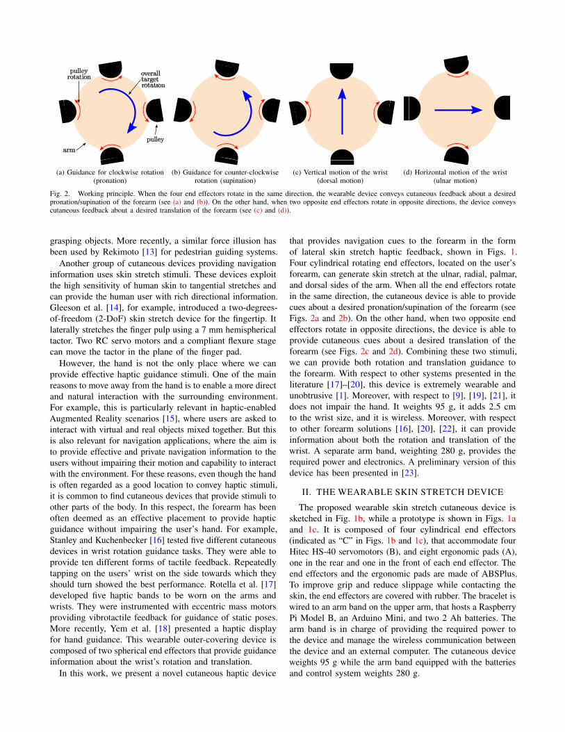
Fig. 2. Working principle. When the four end effectors rotate in the same direction, the wearable device conveys cutaneous feedback about a desiredpronation/supination of the forearm (see (a) and (b)). On the other hand, when two opposite end effectors rotate in opposite directions, the device conveyscutaneous feedback about a desired translation of the forearm (see (c) and (d)).
grasping objects. More recently, a similar force illusion has
been used by Rekimoto [13] for pedestrian guiding systems.
Another group of cutaneous devices providing navigation
information uses skin stretch stimuli. These devices exploit
the high sensitivity of human skin to tangential stretches and
can provide the human user with rich directional information.
Gleeson et al. [14], for example, introduced a two-degrees-
of-freedom (2-DoF) skin stretch device for the fingertip. It
laterally stretches the finger pulp using a 7 mm hemispherical
tactor. Two RC servo motors and a compliant flexure stage
can move the tactor in the plane of the finger pad.
However, the hand is not the only place where we can
provide effective haptic guidance stimuli. One of the main
reasons to move away from the hand is to enable a more direct
and natural interaction with the surrounding environment.
For example, this is particularly relevant in haptic-enabled
Augmented Reality scenarios [15], where users are asked to
interact with virtual and real objects mixed together. But this
is also relevant for navigation applications, where the aim is
to provide effective and private navigation information to the
users without impairing their motion and capability to interact
with the environment. For these reasons, even though the hand
is often regarded as a good location to convey haptic stimuli,
it is common to find cutaneous devices that provide stimuli to
other parts of the body. In this respect, the forearm has been
often deemed as an effective placement to provide haptic
guidance without impairing the user’s hand. For example,
Stanley and Kuchenbecker [16] tested five different cutaneous
devices in wrist rotation guidance tasks. They were able to
provide ten different forms of tactile feedback. Repeatedly
tapping on the users’ wrist on the side towards which they
should turn showed the best performance. Rotella et al. [17]
developed five haptic bands to be worn on the arms and
wrists. They were instrumented with eccentric mass motors
providing vibrotactile feedback for guidance of static poses.
More recently, Yem et al. [18] presented a haptic display
for hand guidance. This wearable outer-covering device is
composed of two spherical end effectors that provide guidance
information about the wrist’s rotation and translation.
In this work, we present a novel cutaneous haptic device
that provides navigation cues to the forearm in the form
of lateral skin stretch haptic feedback, shown in Figs. 1.
Four cylindrical rotating end effectors, located on the user’s
forearm, can generate skin stretch at the ulnar, radial, palmar,
and dorsal sides of the arm. When all the end effectors rotate
in the same direction, the cutaneous device is able to provide
cues about a desired pronation/supination of the forearm (see
Figs. 2a and 2b). On the other hand, when two opposite end
effectors rotate in opposite directions, the device is able to
provide cutaneous cues about a desired translation of the
forearm (see Figs. 2c and 2d). Combining these two stimuli,
we can provide both rotation and translation guidance to
the forearm. With respect to other systems presented in the
literature [17]–[20], this device is extremely wearable and
unobtrusive [1]. Moreover, with respect to [9], [19], [21], it
does not impair the hand. It weights 95 g, it adds 2.5 cm
to the wrist size, and it is wireless. Moreover, with respect
to other forearm solutions [16], [20], [22], it can provide
information about both the rotation and translation of the
wrist. A separate arm band, weighting 280 g, provides the
required power and electronics. A preliminary version of this
device has been presented in [23].
II. THE WEARABLE SKIN STRETCH DEVICE
The proposed wearable skin stretch cutaneous device is
sketched in Fig. 1b, while a prototype is shown in Figs. 1a
and 1c. It is composed of four cylindrical end effectors
(indicated as “C” in Figs. 1b and 1c), that accommodate four
Hitec HS-40 servomotors (B), and eight ergonomic pads (A),
one in the rear and one in the front of each end effector. The
end effectors and the ergonomic pads are made of ABSPlus.
To improve grip and reduce slippage while contacting the
skin, the end effectors are covered with rubber. The bracelet is
wired to an arm band on the upper arm, that hosts a Raspberry
Pi Model B, an Arduino Mini, and two 2 Ah batteries. The
arm band is in charge of providing the required power to
the device and manage the wireless communication between
the device and an external computer. The cutaneous device
weights 95 g while the arm band equipped with the batteries
and control system weights 280 g.

Fig. 3. Kinematic scheme of one skin stretch module. The proposedwearable device is composed of four skin stretch modules.
If no slip occurs, the movement of one of the end effectors
onto the skin Î∆S directly results in the same amount of skin
stretch. This movement can be calculated as
Î∆S =∆θp ⋅ r, (1)
where r = 20 mm is the end effector radius (see Fig. 3), and
∆θp is the commanded angle motion in radians.
To maximize the comfort and effectiveness of the haptic
device, we placed it 10 cm proximal to the lunate bone (i.e.,
near the wrist) and fasten it until the end effector applied
a force of 4 N normal to the skin. More details about this
choice can be found in [23].
III. EXPERIMENTAL EVALUATION
To evaluate the effectiveness of our device in providing
informative skin stretch sensations, we carried out two
experiments of haptic navigation.
A. Experiment #1: preliminary arm guidance
In the first experiment, we aim at evaluating the guiding
capabilities of our device in a simple wrist navigation task.
1) Experimental setup and task: The experimental setup
is composed of our wearable skin stretch device, as shown in
Fig. 1. The force applied on the forearm skin was registered
at the beginning of the experiment using four piezoresistive
Force Sensing Resistor (FSR) sensors placed between the
end effectors and the forearm. The FSR sensors were then
removed to enable the subject to carry out the tasks. At
the end of the experiment, the sensors were re-positioned to
register any significant change in the fastening force. The
maximum reduction of fastening force we registered was
0.6 N, which we found acceptable. No subject reported any
significant change in the fastening force or in the positioning
of the device.
To detect pronation, supination, and translation of the
forearm, we used a Leap Motion tracker.
The task consisted of rotating or translating the forearm
following the navigation cues provided by the skin stretch
device, being as accurate as possible. A video of the experi-
ment is available as supplemental material. To avoid external
distractions, subjects wore noise-canceling headphones and
were blindfolded. Reference rotations and translations were
0
2
4
6
8
10
12
(a) Rotation error (degrees)
0
20
40
60
80
100
120
(b) Translation error (mm)
Fig. 4. Experiment #1. Subjects were asked to rotate/translate the forearmfollowing the navigation information provided by the device, being as accurateas possible. Absolute orientation and position error provided a measure ofperformance. Mean and 95% confidence interval are plotted.
uniformly chosen in the θr ∈ [10,60]○ and dr ∈ [1,10] cm
ranges, respectively. The Leap Motion tracked the position
and orientation of the forearm. The task started when the
subject moved the forearm for the very first time and ended
when the subject felt to be in the right position.
2) Subjects and methods: Ten participants were involved
in this first experiment, including three women and seven
men. Seven participants had previous experience with haptic
interfaces. Before starting the task, the experimenter explained
the procedure and spent about two minutes adjusting the setup
to be comfortable. One practice trial was allowed.
Each subject carried out thirty-six randomized trials of the
navigation task, with twelve repetitions for each feedback
condition:
● navigation feedback regarding the desired rota-
tion/translation of the forearm using our wearable skin
stretch device (condition CF),
● navigation feedback regarding the desired rota-
tion/translation of the forearm using visual cues (condi-
tion V),
● no navigation feedback (condition N),
In the first condition CF, the wearable device provides
haptic navigation feedback about pronation, supination, and
translation of the forearm, as detailed in Sec. II and shown
in Fig. 2. Subjects should thus rotate/translate their forearm
following the cutaneous information provided by the device.
The closer the subject is to the target orientation/position of
the forearm, the less stretch the device applies to the skin.
When the subject reaches the desired orientation/position, the
device applies no skin stretch to the forearm. Another viable
control policy would have been to directly provide the target
hand pose, so that subjects would have had to try maintaining
a constant skin stretch. However, applying a constant stretch
stimulus for a long period results in a reduced sensation [24].
For this reason, we decided to provide information about the
error between the current and target hand poses. To avoid slip-
page and achieve the highest accuracy, the cutaneous device
maps the target rotation/translation to a skin stretch in the
[−8.75,8.75] mm range, corresponding to a pulley rotation
in the θp ∈ [−25,25]○ range [23]. This proportional control

policy for controlling the device rotations and translation
during the experiment is summarized by the two algorithms
below.
Algorithm 1: Skin stretch control policy for rotations
set target rotation θrforeach time step do
measure current rotation θm
θp = 25(θr − θm)∣θr ∣
.
if ∣θp∣ > 25 thenθp = sgn(θp)25.
end
apply rotation θp to all the pulleys (see Fig. 2).
exit when subject feels to be at the right orientation.end
Algorithm 2: Skin stretch control policy for translations
set target translation drforeach time step do
measure current translation dm
θp = 25(dr − dm)∣dr ∣
.
if ∣θp∣ > 25 thenθp = sgn(θp)25.
end
apply rotations ±θp to two opposite pulleys,
according to the target direction of motion (see Fig. 2).
exit when subject feels to be at the right position.end
In condition V, no cutaneous feedback is provided to the
subjects. An LCD screen is placed in front of them and
an arrow indicates the target direction or orientation. The
length of the arrow indicates how far the subject is from
the target direction or orientation. In condition N, neither
cutaneous nor visual feedback is provided to the subjects. At
the beginning of the task, the experimenter communicates
the target movement to the subject.
The ten participants carried out twelve repetitions of the
navigation task in each feedback condition, two times for
each navigation modality: pronation (Fig. 2a), supination
(Fig. 2b), translation to the right (Fig. 2d), translation to the
left, elevation (Fig. 2c), and lowering of the forearm.
3) Results: Rotation and position errors as well as com-
pletion time provided a measure of performance. Low values
for these metrics indicate the best performance.
Fig. 4a shows the average absolute rotation error at the end
of the task. All the data passed the Shapiro-Wilk normality
test and Mauchly’s Test of Sphericity. A one-way repeated-
measures ANOVA test showed statistically significant changes
between the feedback conditions (F(2, 18) = 35.351, p <
0.001). Post-hoc analysis with Bonferroni correction showed
statistically significant differences between CF vs. N with
p < 0.001 and V vs. N with p = 0.001. Fig. 4b shows
the average absolute translation error at the end of the task
for each condition. All the data passed the Shapiro-Wilk
normality test. Mauchly’s Test of Sphericity indicated that
the assumption of sphericity was violated (χ2= 22.286, p <
0.001). A one-way repeated-measures ANOVA test with a
Greenhouse-Geisser correction showed statistically significant
changes between the feedback conditions (F(1.016, 9.141) =
13.267, p < 0.001). The Greenhouse-Geisser correction is used
when the assumptions of sphericity or equal variances are
violated, as in this case. It corrects the analysis by calculating
new degrees of freedom and a new significance value p,
so that a valid F-ratio can be obtained. Post-hoc analysis
with Bonferroni correction showed statistically significant
differences between all conditions: CF vs. V, p = 0.032; CF
vs. N, p = 0.020; and V vs. N, p = 0.016. Finally, we also
measured the completion time. All the data passed the Shapiro-
Wilk normality test and Mauchly’s Test of Sphericity. A
one-way repeated-measures ANOVA indicated no significant
difference in the performance among feedback conditions.
Average completion time was 5.06 ± 1.02 s (mean ± SD).
Immediately after the experiment, subjects were also asked
to choose the condition they preferred the most. Condition
CF was preferred by two subjects, while condition V was
preferred by eight subjects.
B. Experiment #2: robotic telemanipulation
In the second experiment, we aim at evaluating the guiding
capabilities of our device in a robotic telemanipulation task.
1) Experimental setup and task: The experimental setup
and remote environment are shown in Fig. 5. The master side
is composed of our skin stretch device, as shown in Fig. 1.
Moreover, a Leap Motion tracker is in charge of registering
the position, orientation, and grasping configuration of the
operator’s hand. The hand grasping configuration, i.e., how
closed the hand is, is measured by considering the radian
angle gh between the index finger’s distal phalanx direction
hf and the hand direction hw (see Fig. 1a and [25]),
gh = cos−1 (hf ⋅ hw) . (2)
The slave robot is composed of the anthropomorphic Pisa/IIT
SoftHand soft robotic hand, attached to a 6-DoF Universal
Robot 5 manipulator (Universal Robots A/S, Denmark). A
small camera is attached to the robot’s wrist, showing the
environment in front of the robotic hand. The SoftHand uses
only one actuator to activate its adaptive synergy [26]. The
index, middle, ring, and little fingers have four phalanges,
while the thumb has three. The hand is connected to a
flange, to be fixed at the manipulator’s end effector, through a
compliant wrist allowing for three passively compliant degrees
of freedom. The motor of the hand is driven by commanding
a grasping variable gr ∈ [0,1], which sets the hand closure.
The 6-DoF manipulator is able to move the end effector at
up to 1 m/s and each joint at 180 deg/s. Its repeatability
is ±0.1 mm for quick-precision handling with a maximum
payload of 5 kg [27].
The desired pose of the robotic hand and wrist at time t,BTD(t), is commanded using a mapping between the Soft-
Hand and the user’s hand, tracked by the Leap Motion [25].

(a) Master side.
(b) Slave side.
Fig. 5. Experiment #2. The master system is composed of the wearable skinstretch device and a Leap Motion controller. The slave system is composedof the Pisa/IIT SoftHand soft robotic hand attached to the end effector ofa 6-DoF Universal Robot 5 manipulator. A camera attached to the robot’swrist shows the remote environment to the human operator. The desiredpose and grasping configuration of the robotic hand are controlled by thehuman operator as detailed in Sec. III-B.1. The keyboard works as a clutch.
The keyboard works as a clutch. All coordinate frames but
the one on the robot base B are shown in Figs. 5 and 6.
Frame B has its origin on the robot base, with the z axis
orthogonal to the table (pointing up), the x axis parallel to the
table (pointing toward the obstacle), and the y consequently
defined. When the space key is pressed, the current pose
of the user’s hand with respect to the Leap Motion baseLTH ∈ SE(3) and the robot’s end effector pose with respect
to its base BTE are saved:
LTH(0) =L TH(t)
BTE(0) =B TE(t).
As the user moves his hand, the desired end effector pose is
calculated according to eq. (3), using the poses saved when
the user started pressing the clutch, such that their relative
motions are equal, i.e., E0TD =H0 TH ,
BTD(t) =B TE(0) ⋅L T
−1
H (0) ⋅LTH(t). (3)
This mapping allows the robot to be commanded in a natural
way while looking at the camera: if the user moves his hand
in the z direction of the H frame, the robot will move along
the z direction of its frame E. This approach also allows the
user to start the motion with the hand at an arbitrary position
with respect to the Leap Motion, enabling the user to also
pause, move to a more comfortable or suitable position, and
then resume the control of the robot.
To also match as closely as possible the grasping configu-
ration of the operator’s hand, we define the input commanded
to the hand DC motor as gr = ghπ−1, where a command of
0% closure is sent when the index is parallel with the palm
direction and 100% closure is commanded when the index
finger is bent 180○ (see eq. (2) and Fig. 1a).
The remote environment is composed of the slave robot, an
obstacle, and a target object to grasp (i.e., a bottle of water).
The task consisted of moving the slave robot in the remote
environment and picking up the target object, following the
navigation information provided by the device and avoiding
contacts with obstacles (see Fig. 5). A video of the experiment
is available as supplemental material.
2) Subjects and Methods: Ten participants took part in the
experiment, including one women and nine men. Six of them
had previous experience with haptic interfaces. Before starting
the experiment, the experimenter explained the procedure
and spent about three minutes adjusting the setup to be
comfortable. One practice trial was allowed.
We considered two different trajectories (tr vs. tp), two
different orientations of the target object to grasp (od vs. ou),
and three different haptic feedback conditions (CF vs. V vs.
N), ending up with 2 (trajectories) × 2 (object orientations) ×3 (feedbacks) = 12 different experimental conditions. The two
trajectories are shown in Fig. 6. The first trajectory moves the
robot following a rectangular shape around the obstacle (tr),
while the second one moves the robot following a parabolic
shape around the obstacle (tp). The water bottle to grasp
can be either standing (ou) or laying (od) on the table. The
configuration of the bottle on the table also defines the final
target orientation for the robotic hand with respect to the B
frame, chosen to enable a successful grasp: γ = rot(x)B = 0○
for od (hand palm parallel to the table) and γ = rot(x)B = 90○
for ou (hand palm perpendicular to the table), i.e., with
the palm parallel to the bottle. The starting position and
orientation of the hand are chosen randomly around the
first point of the trajectory, as shown in Fig. 6. Finally,
the human operator receives navigation feedback about the
desired trajectory and orientation through our skin stretch
device (CF), through sensory substitution via visual feedback
(V), or receive no feedback at all (N).
Each trajectory is divided into 60 equidistant points (green
squares in Fig. 6). Given the hand position, the current target
point is defined as the point along the trajectory which comes
next after the one closest to the robotic hand (red square in
Fig. 6). All the points except the last one commands a target
orientation of rot(x)B = 0. The target orientation for the last
point depends on the bottle configuration, as specified above.
The control policy for this experiment is summarized in the

(a) Trajectory tr with the bottle standing on the table (ou) (b) Trajectory tp with the bottle laying on the table (od)
Fig. 6. Experiment #2. The task consisted of moving the slave robot in the remote environment and picking up the plastic bottle, following the navigationinformation provided by the device and avoiding contacts with obstacles. A video of the experiment is available as supplemental material.
algorithm reported below.
Algorithm 3: Selection of target position and orientation
set target trajectory ∗if bottle orientation ou then
set final hand orientation to γ = 90○
else if bottle orientation od thenset final hand orientation to γ = 0○
end
foreach time step domeasure current robot position dmmeasure current robot orientation θmfind closest point t∗(k), k = 1, . . . ,60 in trajectory ∗if k < 60 then
set the next point t∗(k + 1) as the target
set target orientation rot(x)B to 0○
else if k = 60 thenset last point t∗(60) as the target
set target orientation rot(x)B to γend
apply stimuli according to the feedback condition.
exit when bottle is grasped and liftedÔ⇒ success, or
exit when task fails Ô⇒ failureend
In condition CF, our wearable cutaneous device provides
the subject with navigation information about the translation
and orientation of the robotic hand. Similarly to Sec. III-A,
the more the subject rotates/translates the forearm toward
the target point of the trajectory, the less stretch the device
applies to the skin. As before, to avoid slippage and provide
the highest accuracy, the cutaneous device always maps
the target rotation/translation to a skin stretch in the range
[−8.75,8.75] mm. Once the target position and orientation is
defined as per Algorithm 3, skin stretch stimuli are provided
to the human operator combining the control policies detailed
in Algorithms 1 and 2. In condition V, no cutaneous feedback
is provided to the subjects. An arrow, superimposed on the
camera view of the remote environment, indicates the target
direction and orientation of the robotic hand. As for Sec. III-
A, the length of the arrow indicates how far the subject is
from the target direction or orientation. In condition N, no
navigation feedback is provided to the subjects. Before the
beginning of the task, the experimenter shows the subject a
picture of the target trajectory and orientation superimposed
to the environment, e.g., Fig. 6a or Fig. 6b. The operator has
then to rely only on the visual information provided by the
camera to complete the grasping task. Subjects performed
twenty-four repetitions of the navigation task, two for each
experimental condition.
3) Results: Translation error, orientation error, and out-
come of the task were measures of performance.
Fig. 7a shows the average absolute orientation error,
calculated as the RMS of the difference in orientation between
the robotic hand and the target orientation during the task. All
the data passed the Shapiro-Wilk normality test and Mauchly’s
Test of Sphericity. A one-way repeated-measures ANOVA
test revealed statistically significant changes between the
feedback conditions (F(2, 18) = 24.408, p < 0.001). Post-
hoc analysis with Bonferroni correction revealed statistically
significant difference between CF vs. N with p = 0.003 and
V vs. N with p = 0.001. Fig. 7b shows the average absolute
translation error, calculated as the RMS of the distance
between the robotic hand and the target trajectory during
the task. All the data passed the Shapiro-Wilk normality test.
Mauchly’s Test of Sphericity indicated that the assumption
of sphericity had been violated (χ2= 22.450, p < 0.001). A
one-way repeated-measures ANOVA test with a Greenhouse-
Geisser correction revealed statistically significant changes
between the feedback conditions (F(1.031, 9.280) = 25.387,
p = 0.001). Post-hoc analysis with Bonferroni correction
revealed statistically significant difference between conditions
CF vs. N, p = 0.002; and V vs. N, p = 0.002. Fig. 7c shows
the average success rate of the task. A task was considered
successfully completed when the slave robot was able to grasp
the bottle and lift it from the ground. A Friedman test showed
a statistically significant difference between the means of the
feedback conditions (χ2(2) = 8.909, p = 0.012). Post hoc
analysis with Bonferroni correction revealed a statistically
significant difference between conditions CF vs. N (p = 0.002)

0
5
10
15
(a) Rotation error (degrees)
0
20
40
60
80
100
120
140
(b) Translation error (mm)
0
0.2
0.4
0.6
0.8
1
(c) Success rate
0
2
4
6
8
10
12
(d) Perceived effectiveness
Fig. 7. Experiment #2. RMS orientation and position error, success rate, and perceived effectiveness provided a measure of performance for conditions CF(in blue), V (in red), and N (in green). Mean and 95% confidence interval are plotted.
and V vs. N (p = 0.004). The failures were due to too high
collisions forces between the robot and the obstacle, which
caused the manipulator to go into protective mode. We also
measured the completion time. All the data passed the Shapiro-
Wilk normality test and Mauchly’s Test of Sphericity. A
one-way repeated-measures ANOVA indicated no significant
difference in the performance among feedback conditions.
Average completion time was 168.93 ± 10.52 s (mean ± SD).
We also tested whether the task completion time affected the
task performance. Our hypothesis is that subjects who took
more time were able to also achieve higher performance in the
considered metrics. A Pearson’s product-moment correlation
was run to assess the relationship between this distance and
the error in following the desired trajectory with the gripper.
A preliminary analysis showed that the relationship was linear
with normally distributed variable, according to the Shapiro-
Wilk test, and there were no outliers. There was a strong
positive correlation between the completion time vs. rotation
error (r(x) = 0.750, p < 0.001) and translation error (r(x) =
0.880, p < 0.001), confirming our hypothesis.
Besides this evaluation, we also assessed the users’ ex-
perience. Immediately after the experiment, subjects were
asked to complete a questionaire that used bipolar Likert-
type eleven-point scales, reporting the effectiveness of each
feedback condition in completing the given task. Figure 7d
shows the perceived effectiveness of the three feedback
conditions. A Friedman test showed a statistically significant
difference between the means of the feedback conditions
(χ2(2) = 16.270, p < 0.001). Post hoc analysis with Bonfer-
roni correction revealed a statistically significant difference
between conditions CF vs. N (p = 0.002) and V vs. N (p
= 0.004). Finally, subjects were also asked to choose the
condition they preferred the most. Condition CF was preferred
by five subjects and condition V was preferred by five subjects.
No subject reported any significant change in the fastening
force or in the positioning of the device during the task.
IV. DISCUSSION AND CONCLUSIONS
In this paper we presented a wearable cutaneous device able
to provide navigation cues through lateral skin stretch haptic
feedback. The device is shown in Figs. 1. Four rotating end
effectors with cylindrical shape can generate skin stretches
independently at the ulnar, radial, palmar, and dorsal sides of
a user’s forearm. When the end effectors all rotate in the same
direction, the device provides cutaneous cues about a desired
pronation/supination of the forearm. When two opposite end
effectors rotate in opposite directions, the device provides
cutaneous cues about a desired translation of the forearm.
The device weights 95 g, it adds only 2.5 cm to the wrist
size, and it is wireless. A separate arm band, weighting 280 g,
provides the required power and electronics.
We carried out two experiments of haptic navigation,
enrolling a total of 20 subjects. In the first experiment,
subjects had to translate and rotate the forearm toward
a target position and orientation, respectively. Our haptic
device (CF) and sensory substitution with visual feedback (V)
significantly improved the performance of the task with
respect to providing no navigation feedback (N). Sensory
substitution with visual feedback outperformed cutaneous
feedback in one metric. Finally, most subjects preferred visual
feedback over cutaneous feedback, as they found the visual
information more natural and requiring less concentration
with respect to the cutaneous one. Nonetheless, this large
difference in preference (8 vs. 2 subjects for condition V)
did not reflect the task performance. In fact, a significant
lower error of condition V vs. condition CF was found only
for the translation metric (see Fig. 4b), while in the rotation
metric condition CF performed even better than condition
V (although no statistically significant difference was found,
see Fig. 4a).
In the second experiment, subjects were asked to control
the motion and orientation of a 6-DoF robotic manipulator to
grasp and lift a target object. Conversely to Experiment #1,
this time condition CF was more appreciated by the subjects,
who considered it as effective as visual feedback. However,
subjects again reported the visual condition to be more natural
with respect to the cutaneous one. Nonetheless, 9 subjects out
of 10 reported that in condition V it was hard to concentrate,
at the same time, on the arrow indicating the target hand pose
and on the camera view of the remote environment (see top
of Fig. 5a). In this respect, providing navigation information
through the skin stretch device prevented an overload of
the visual channel. Similar results have been demonstrated
also for other teleoperation applications, where providing

cutaneous feedback outperformed sensory substitution via
visual cues [28]–[31]. Results also showed that cutaneous
feedback and sensory substitution with visual feedback
significantly improved the performance of the task with
respect to providing no navigation feedback. No significant
difference was found between conditions CF and V.
Our skin stretch device was proven to be a viable solution
for navigation feedback in human guidance and robotic
telemanipulation systems. However, haptic guidance was still
found to be less natural to follow than visual guidance. In
this respect, we should take into account that we are used
everyday to follow visual navigation cues (e.g., turn-by-turn
car navigation systems, road signs), while we are not used
to follow haptic navigation stimuli at all. In this respect,
we expect more training to improve the performance of the
haptic modality. Moreover, while visual cues may be superior
when there are no other cues to follow, whenever the operator
receives more than one information flow through the visual
channel, providing haptic feedback seems a very good option.
This is a common situation in robotic teleoperation, where the
human operator looks at the camera visual stream and, at the
same time, is provided with additional information about the
forces exerted by the slave robot, a predetermined trajectory to
follow, or the presence of surrounding obstacles. While these
pieces of information can be superimposed on the screen, as
we have done in condition V of Experiment #2, our results
show that using haptic feedback can provide comparable
performance without overloading the visual channel – proving
cutaneous feedback to be the best choice.
In the future, we plan to run more experiments to study how
the performance and subjects’ preference change after some
training. We also plan to test the effect of providing navigation
information using visual and skin stretch cues together. Finally,
we also plan to run a longer evaluation session, in order to
understand if the current fasting mechanism is capable of
keeping the device in place during a prolonged use.
REFERENCES
[1] C. Pacchierotti, S. Sinclair, M. Solazzi, A. Frisoli, V. Hayward, andD. Prattichizzo, “Wearable haptic systems for the fingertip and thehand: taxonomy, review, and perspectives,” IEEE Trans. Haptics, 2017.
[2] F. Chinello, C. Pacchierotti, M. Malvezzi, and D. Prattichizzo, “Athree revolute-revolute-spherical wearable fingertip cutaneous devicefor stiffness rendering,” IEEE Trans. Haptics, 2017.
[3] C. Pacchierotti, Cutaneous haptic feedback in robotic teleoperation,ser. Springer Series on Touch and Haptic Systems, 2015.
[4] Z. F. Quek, S. B. Schorr, I. Nisky, A. M. Okamura, and W. R.Provancher, “Sensory augmentation of stiffness using fingerpad skinstretch,” in Proc. IEEE World Haptics, 2013, pp. 467–472.
[5] ——, “Augmentation of stiffness perception with a 1-degree-of-freedomskin stretch device,” IEEE Trans. Human-Machine Systems, vol. 44,no. 6, pp. 731–742, 2014.
[6] L. Meli, C. Pacchierotti, and D. Prattichizzo, “Experimental evaluationof magnified haptic feedback for robot-assisted needle insertion andpalpation,” International Journal of Medical Robotics and Computer
Assisted Surgery, 2017.
[7] C. Pacchierotti, A. Tirmizi, G. Bianchini, and D. Prattichizzo, “Enhanc-ing the performance of passive teleoperation systems via cutaneousfeedback,” IEEE Trans. Haptics, vol. 8, no. 4, pp. 397–409, 2015.
[8] C. Pacchierotti, L. Meli, F. Chinello, M. Malvezzi, and D. Prattichizzo,“Cutaneous haptic feedback to ensure the stability of robotic teleoper-ation systems,” International Journal of Robotics Research, vol. 34,no. 14, pp. 1773–1787, 2015.
[9] A. Spiers and A. Dollar, “Design and evaluation of shape-changinghaptic interfaces for pedestrian navigation assistance,” IEEE Trans.
Haptics, 2016.[10] Y. Imamura, H. Arakawa, S. Kamuro, K. Minamizawa, and S. Tachi,
“Hapmap: Haptic walking navigation system with support by the senseof handrail,” in Proc. ACM SIGGRAPH – Emerging Tech., 2011, p. 6.
[11] F. Hemmert, S. Hamann, M. Lowe, J. Zeipelt, and G. Joost, “Shape-changing mobiles: tapering in two-dimensional deformational displaysin mobile phones,” in Proc. CHI, 2010, pp. 3075–3080.
[12] T. Oron-Gilad, J. L. Downs, R. D. Gilson, and P. A. Hancock,“Vibrotactile guidance cues for target acquisition,” IEEE Trans. Systems,
Man, and Cybernetics, Part C, vol. 37, no. 5, pp. 993–1004, 2007.[13] J. Rekimoto, “Traxion: a tactile interaction device with virtual force
sensation,” in Proc. ACM SIGGRAPH – Emerging Tech., 2014, p. 25.[14] B. T. Gleeson, S. K. Horschel, and W. R. Provancher, “Design of
a fingertip-mounted tactile display with tangential skin displacementfeedback,” IEEE Trans. Haptics, vol. 3, no. 4, pp. 297–301, 2010.
[15] M. Maisto, C. Pacchierotti, F. Chinello, G. Salvietti, A. De Luca, andD. Prattichizzo, “Evaluation of wearable haptic systems for the fingersin augmented reality applications,” IEEE Trans. Haptics, 2017.
[16] A. Stanley, K. J. Kuchenbecker et al., “Evaluation of tactile feedbackmethods for wrist rotation guidance,” IEEE Trans. Haptics, vol. 5,no. 3, pp. 240–251, 2012.
[17] M. F. Rotella, K. Guerin, X. He, and A. M. Okamura, “Hapi bands:a haptic augmented posture interface,” in IEEE Haptics Symposium
(HAPTICS), 2012, pp. 163–170.[18] V. Yem, M. Otsuki, and H. Kuzuoka, “Development of wearable outer-
covering haptic display using ball effector for hand motion guidance,”in Haptic Interaction, 2015, pp. 85–89.
[19] T. Amemiya and H. Sugiyama, “Orienting kinesthetically: A haptichandheld wayfinder for people with visual impairments,” ACM Trans.
Accessible Computing, vol. 3, no. 2, p. 6, 2010.[20] Y. Kuniyasu, M. Sato, S. Fukushima, and H. Kajimoto, “Transmission
of forearm motion by tangential deformation of the skin,” in Proc. 3rd
Augmented Human International Conference, 2012, p. 16.[21] R. L. Koslover, B. T. Gleeson, J. T. de Bever, and W. R. Provancher,
“Mobile navigation using haptic, audio, and visual direction cues with ahandheld test platform,” IEEE Trans. Haptics, vol. 5, no. 1, pp. 33–38,2012.
[22] T. Nakamura, N. Nishimura, M. Sato, and H. Kajimoto, “Developmentof a wrist-twisting haptic display using the hanger reflex,” in Proc.
Conf. Advances in Computer Entertainment Technology, 2014, p. 33.[23] F. Chinello, C. Pacchierotti, N. G. Tsagarakis, and D. Prattichizzo,
“Design of a wearable skin stretch cutaneous device for the upper limb,”in Proc. IEEE Haptics Symposium (HAPTICS), 2016, pp. 14–20.
[24] P. t. Burgess and E. Perl, “Cutaneous mechanoreceptors and nocicep-tors,” in Somatosensory system. Springer, 1973, pp. 29–78.
[25] J. Bimbo, C. Pacchierotti, M. Aggravi, N. G. Tsagarakis, and D. Prat-tichizzo, “Teleoperation in cluttered environments with distributedwearable haptic feedback,” in Proc. IEEE/RSJ Int. Conf. Intelligent
Robots and Systems, 2017.[26] M. G. Catalano, G. Grioli, E. Farnioli, A. Serio, C. Piazza, and
A. Bicchi, “Adaptive synergies for the design and control of the pisa/iitsofthand,” Int. J. Robot. Res., vol. 33, no. 5, pp. 768–782, 2014.
[27] E. Ostergaard, “Lightweight robot for everybody [industrial activities],”IEEE Robot. Autom. Mag., vol. 19, no. 4, pp. 17–18, 2012.
[28] C. Pacchierotti, D. Prattichizzo, and K. J. Kuchenbecker, “Cutaneousfeedback of fingertip deformation and vibration for palpation in roboticsurgery,” IEEE Trans. Biomed. Eng., vol. 63, no. 2, pp. 278–287, 2016.
[29] M. Abayazid, C. Pacchierotti, P. Moreira, R. Alterovitz, D. Prattichizzo,and S. Misra, “Experimental evaluation of co-manipulated ultrasound-guided flexible needle steering,” Int J Med Robot, vol. 12, no. 2, pp.219–230, 2016.
[30] D. Prattichizzo, C. Pacchierotti, and G. Rosati, “Cutaneous forcefeedback as a sensory subtraction technique in haptics,” IEEE Trans.
Haptics, vol. 5, no. 4, pp. 289–300, 2012.[31] C. Pacchierotti, M. Abayazid, S. Misra, and D. Prattichizzo, “Tele-
operation of steerable flexible needles by combining kinesthetic andvibratory feedback,” IEEE Trans. Haptics, vol. 7, no. 4, pp. 551–556,2014.