design and control of facts-based high performance microgrid · 2016-01-09 · design and control...
TRANSCRIPT

Design and Control of FACTS-based high Performance Microgrid
By
Owais Muneer
A Thesis Submitted in Partial Fulfillment
of the Requirements for the Degree of
Master of Applied Science
In
The Faculty of Electrical and Computer Engineering
University of Ontario Institute of Technology
December 2015
© Copyright by Owais Muneer, 2015

Design and Control of FACTS-based high performance Microgrid
1
Acknowledgement
I would like to express my sincere appreciation to my supervisor, Prof. Hossam A. Gabbar for his
encouragement, supervision and support. In addition; I would like to thank Dr. Ahmed Abdelmaksoud
for their technical guidance. I take this opportunity to record my sincere thanks to all the faculty
members of the Department of Electrical and Computer Engineering of UOIT for providing me with
resources. Above all, I would like to express my appreciation to my family and closest friends for their
love, perpetual support and honorable commitment to my education.

Design and Control of FACTS-based high performance Microgrid
2
Abstract
The current power grid introduces many limitations and challenges in a world that is heavily
dependent on electricity. Many government agencies, utility companies, researchers and engineers
in the electric power industry have envisioned of transforming the existing grid into MicroGrid.
To facilitate domestic consumers’ ratings and needs, a microgrid has been developed that includes
Distributed Energy Resources (DER). It is expected to be an intelligent, sustainable, resilient and
reliable power grid suitable for the 21st century economy. Some of the main concerns for any grid
are power quality and efficiency as well as reactive and active power reliability for consumers. To
manage active and reactive power Flexible AC Transmission System (FACTS) technology is used
to improve power quality and efficiency. Since FACTS technologies have been developed, much
research has been done to acquire more accurate and reliable techniques and algorithms to
implement FACTS in the power system. The current microgrid scheme implemented with FACTS,
produces a highly efficient response monitored with different KPI indicators of the microgrid. A
newly developed AC/DC microgrid design with FACTS technology includes DER, which consist
of DC batteries, wind Turbines, PV systems (Solar photovoltaic system) and diesel generators.
Modulated Power Filter Compensators (MPFC) for AC and Green Plug Filter Compensators
(GPFC) for DC are used as FACTS controller. Optimization based on genetic algorithms and
intelligent control through fuzzy logic, are defined to optimize the performance of the microgrid.
Optimization and intelligent control are accomplished by self-adapting the controller gains and
converters gains to achieve the best microgrid energy utilization, stabilization of voltage and
reduction inrush current conditions. Key performance indicators are as follows: bus voltages
stabilizing, feeder losses reduction, power factor enhancement, improvement of power quality and
reduction of the total harmonic distortion at AC interface buses that are compared with and without
FACTS criterion. The AC/DC microgrid is modeled in both grid and islanded connected modes.

Design and Control of FACTS-based high performance Microgrid
3
List of Abbreviation:
AVR
DVR
FACTS
FL
GA
GTO
HVDC
IGBT
IGCT
LPF
LP
PSS
PWM
PQ
SSR
SSSC
STATCOM
SVC
TCBR
TCR
TCSC
UPFC
VSC
VSI
Automatic Voltage Regulator
Dynamic Voltage Restorer
Flexible AC Transmission System
Fuzzy Logic
Genetic Algorithm
Gate Turn-Off (Thyristor)
High Voltage Direct Current
Insulated Gate Bipolar Transistor
Integrated Gate Commutated Thyristor
Low Pass Filter
Low Pressure (turbine)
Power System Stabilizer
Pulse Width Modulation
Power Quality
Subsynchronous Resonance
Static Synchronous Series Compensator
Static (Synchronous) Compensator
Static Var Compensator
Thyristor Controlled Braking Resistor
Thyristor Controlled Reactor
Thyristor Controlled Series Capacitor
Unified Power Flow Controller
Voltage Source Converter
Voltage Source Inverter

Design and Control of FACTS-based high performance Microgrid
4
FACTS (Flexible AC Transmission System):
Alternating current transmission system incorporating power electronic based and other static
controllers to enhance controllability and increase power transfer capability [85].
FACTS is defined by the IEEE as "a power electronic based system and other static equipment
that provide control of one or more AC transmission system parameters to enhance controllability
and increase power transfer capability."
According to Siemens "FACTS Increase the reliability of AC grids and reduce power delivery
costs. They improve transmission quality and efficiency of power transmission by supplying
inductive or reactive power to the grid.

Design and Control of FACTS-based high performance Microgrid
5
Table of Content
Abstract ........................................................................................................................................... 2
1 Introduction ........................................................................................................................... 12
1.1 Objectives ....................................................................................................................... 12
1.2 Approach ........................................................................................................................ 12
1.3 Research Tasks ............................................................................................................... 13
1.4 Motivation ...................................................................................................................... 13
2 Literature Survey ................................................................................................................... 14
2.1 FACTS Concept ............................................................................................................. 15
2.2 Microgrid Concept ......................................................................................................... 16
3 Thesis Overview ........................................................................................................................ 30
3.1 Proposed framework ........................................................................................................... 31
3.2 Proposed Methodology ....................................................................................................... 32
3.3 Proposed Microgrid Scenarios ............................................................................................ 34
4 Modeling of FACTS Devices ................................................................................................ 35
4.1 Introduction .................................................................................................................... 35
4.2 FACTS devices .............................................................................................................. 35
4.3 Thyristor Controlled Reactor (TCR) .............................................................................. 36

Design and Control of FACTS-based high performance Microgrid
6
4.4 Thyristor Based FACTS Devices ................................................................................... 39
4.4.1 Static Var Compensators (SVCs)............................................................................ 39
4.4.2 Thyristor Controlled Series Capacitor (TCSC)....................................................... 41
4.5 SVS Based-FACTS Device ............................................................................................ 47
4.5.1 Static Compensator (STATCOM) .......................................................................... 47
4.5.2 Static Series Synchronous Compensator (SSSC) ................................................... 50
4.6. Unified Power Flow Controller (UPFC) ............................................................................ 53
4.7 Comparisons of FACTS devices ......................................................................................... 56
5 Microgrid Design & Control ...................................................................................................... 61
5.1 Introduction ......................................................................................................................... 61
5.2 Controlling in Microgrid ..................................................................................................... 62
5.2.1 Simple Class or Virtual ‘Prime Mover’ ........................................................................ 62
5.2.2 Master Class or Physical ‘Prime Mover’ ...................................................................... 63
5.3 DER control......................................................................................................................... 65
5.4. Grid-Connected-Mode DER Control ................................................................................. 65
6 Control Design of FACTS-Based Microgrid ............................................................................. 68
6.1 Hybrid AC/DC Microgrid Design ....................................................................................... 68
6.2 Modeling of the hybrid AC/DC Microgrid .................................................................... 71
6.2.1 Wind turbine ........................................................................................................... 71
6.2.2 Photovoltaic ............................................................................................................ 74

Design and Control of FACTS-based high performance Microgrid
7
6.2.3 Fuel Cell .................................................................................................................. 75
6.2.4 Energy Storage Batteries......................................................................................... 75
6.2.5 AC and DC loads .................................................................................................... 76
6.2.6 FACTS Devices ...................................................................................................... 76
6.3 Control Design .................................................................................................................... 79
6.3.1 PID Controller .............................................................................................................. 79
6.3.2 MPFC controlling: ........................................................................................................ 80
6.3.3 GPFC controlling .......................................................................................................... 82
6.3.4 AC/DC Converter controlling: ................................................................................ 83
6.3.5 Genetic Algorithms....................................................................................................... 85
6.3.6 Continuous-Parameter GA ........................................................................................... 85
6.3.7 Self Tunning of PID Controller Using Genetic Algorithm .......................................... 87
6.3.8 Intelligent Controlling .................................................................................................. 88
6.3.9 Integration of GA with Fuzzy ....................................................................................... 89
6.4 Matlab Simulation Block View ........................................................................................... 91
7 Simulation Results and Discussions .......................................................................................... 92
7.1 Grid Mode With/Without FACTS using PID controller ..................................................... 92
7.2 Islanded Mode With/Without FACTS using PID controller ............................................... 96
7.3 Grid With/Without FACTS using intelligent controller .................................................... 99
7.4 Islanded With/Without FACTS using intelligent controller ............................................. 102

Design and Control of FACTS-based high performance Microgrid
8
8 Conclusion ............................................................................................................................... 105
8.1 Future Work ...................................................................................................................... 105
9 References ................................................................................................................................ 106
10 Appendix ................................................................................................................................ 116
AC DER:.............................................................................................................................. 117
DC DER:.............................................................................................................................. 118

Design and Control of FACTS-based high performance Microgrid
9
List of Figures
Figure 2-1 Power system operation .............................................................................................. 14
Figure 3-1 General Thesis Overview ............................................................................................ 30
Figure 3-2 Thesis Framework ....................................................................................................... 31
Figure 3-3 Thesis Methodology .................................................................................................... 33
Figure 3-4 Thesis Scenario ........................................................................................................... 34
Figure 4-1 Thyristor Controlled Reactor .................................................................................... 37
Figure 4-2 Current waveforms in TCR (a) 90o, 180o (b) 100o (c) 130o (d) 150o [16] ............... 38
Figure 4-3 Static VAR compensator (SVC). [33] ......................................................................... 39
Figure 4-4 V-I characteristics. [33] ............................................................................................... 40
Figure 4-5 Thyristor controlled series capacitor (TCSC). [34]..................................................... 42
Figure 4-6 Series compensation vector diagram. [41] .................................................................. 42
Figure 4-7 TCSC reactance vs. firing angle α. [41] ...................................................................... 45
Figure 4-8 Static compensator (STATCOM) ............................................................................... 48
Figure 4-9 V-I characteristic of STATCOM. [55] ........................................................................ 49
Figure 4-10 SSSC Schematic Diagram ......................................................................................... 50
Figure 4-11 UPFC Schematic diagram ......................................................................................... 54
Figure 5-1 Mirogrid Architecture ................................................................................................. 61
Figure 5-2 diagram of a grid-connected DER system with voltage mode [10] ........................... 65
Figure 5-3 Schematic diagram of a grid-connected DER system with current mode [57] ........... 66
Figure 5-4 Schematic diagram of a grid-connected non-dispatchable DER system [57] ............. 67
Figure 6-1 Hybrid AC/DC microgrid ........................................................................................... 69
Figure 6-2 Full schematic of AC/DC microgrid ........................................................................... 70
Figure 6-3 Installed global wind capacity (1997 - 2014) source: gwec.net .................................. 71
Figure 6-4 Wind turbine with fixed speed .................................................................................... 73
Figure 6-5 Recorded and Forecasted PV Capacity. Source: evwind.es ........................................ 74
Figure 6-6 Modulated Power Filter Scheme ................................................................................. 78
Figure 6-7 Green Plug Filter Compensator Scheme ..................................................................... 78
Figure 6-8 MPFC multi-loop error driven scheme ....................................................................... 82
Figure 6-9 GPFC multi-loop error regulating scheme .................................................................. 83

Design and Control of FACTS-based high performance Microgrid
10
Figure 6-10 Overview of Genetic Algorithm................................................................................ 85
Figure 6-11 GA with Fuzzy .......................................................................................................... 89
Figure 6-12 Fuzzy system tuning .................................................................................................. 90
Figure 6-13 Simulink Block view Of Hybird AC/DC microgrid ................................................. 91
Figure 7-1 Voltage, Current, Reactive power and Power Factor at AC bus (VS) ........................ 92
Figure 7-2 Voltage, Current, Reactive power and Power Factor at AC bus (V1) ........................ 93
Figure 7-3 Voltage, Current, Reactive power and Power Factor at AC bus (Vg) ........................ 93
Figure 7-4 Voltage, Current and power at DC bus (Vdc) ............................................................. 93
Figure 7-5 reactive power and Power factors at Vg buses ............................................................ 96
Figure 7-6 Voltage and power at Vd bus ...................................................................................... 96
Figure 7-7 Voltage, Reactive power and Power factors at V1 buses............................................ 97
Figure 7-8 Voltage, Current, Reactive power and Power Factor at AC bus (VL) ........................ 99
Figure 7-9 Voltage, Current, Reactive power and Power Factor at AC bus (V1) ........................ 99
Figure 7-10 Voltage, Current, Reactive power and Power Factor at AC bus (VS) ...................... 99
Figure 7-11 Voltage, Current, Reactive power and Power Factor at AC bus (Vg) .................... 100
Figure 7-12 Voltage, Current and power at DC bus (Vdc) ......................................................... 100
Figure 7-13 Voltage, Reactive power and Power Factor at AC bus (V1)) ................................. 102
Figure 7-14 Voltage, Current, Reactive power and Power Factor at AC bus (Vg) .................... 102
Figure 7-15 Voltage, Current, Reactive power and Power Factor at AC bus (Vdc) .................. 103

Design and Control of FACTS-based high performance Microgrid
11
List of Tables
Table 5-1 Microgrid control method classifications [56] ............................................................. 64
Table 6-1 Wind Turbine Systems [52].......................................................................................... 72
Table 6-2 GA optimization parameters......................................................................................... 88
Table 7-1 Optimal values of PID controller ................................................................................. 94
Table 7-2 the %THD of voltage and current at all AC buses ....................................................... 94
Table 7-3 Optimal values of PID controller ................................................................................. 97
Table 7-4 the %THD of voltage and current at all AC buses ....................................................... 97
Table 7-5 optimal values of PID controller ................................................................................ 101
Table 7-6 the %THD of voltage and current at all AC buses ..................................................... 101
Table 7-7 Optimal values of PID controller ............................................................................... 103
Table 7-8 the %THD of voltage and current at all AC buses ..................................................... 103

Design and Control of FACTS-based high performance Microgrid
12
1 Introduction
1.1 Objectives
The main goal of this study is to design and control a hybrid AC/DC micro grid with
FACTS to enhance performance, efficiency, and quality. In order to achieve main target, the
following objectives are identified:
• Study advanced designs and controllers of MG
• Study advanced types/designs and controllers of FACTS within MG
• Define performance indicators (KPIs) of FACTS design, controller, and MG
• Evaluate overall MG performance using different FACTS designs / controllers, and their
application to building energy conservation
1.2 Approach
Firstly, several researches, journal papers that are related to microgrids and FACTS are
studied and reviewed. Literature reviews are completed on different designs and controllers of
FACTS in microgrid, control strategies for FACTS in microgrid, key performance indicators of
microgrid, and simulation of FACTS devices in microgrid. Based on literature review, SIMULINK
simulation model for defining FACTS in microgrid with fuzzy control are used to analyze
simulation of control and design strategies. Steady state and transient performance of the system
are observed using Matlab/Simulink simulation. Defining KPI for system that differ with and
without FACTS comparisons. Fuzzy logic will be implemented for defined control strategy and
optimized using Genetic algorithm as an intelligent algorithm.

Design and Control of FACTS-based high performance Microgrid
13
1.3 Research Tasks
The following are expected research tasks that will be completed in this thesis:
Literature reviews of microgrid modeling, control and operation
Literature reviews on FACTS modeling, control and operation
Literature reviews on Key performance indicators for microgrid with and without FACTS
Designing and modeling comprehensive microgrid case studies
Designing and modeling different types of FACTS within a microgrid
Control of power quality and stability through FACTS device in a microgrid
MATLAB/Simulink simulation model for the FACTS control in a microgrid
KPI comparison with/ without FACTS in a microgrid
1.4 Motivation
The use of renewable energy in the world is increasing gradually. Economical, technological and
environmental issues are shaping the characteristics of energy generation and transmission in the
power industry. Distributed energy resources (DER) include a wide range of technologies for
example; micro gas turbines, photovoltaic, fuel cells and wind-power. These technologies have
initial lower cost that can lead to benefits in economies and trade. Recent market of oil and gas has
variable and dynamic prices. Developing countries are facing economic challenges due to energy
crisis every year. These countries uses several energy generation techniques to meet country
energy consumption. In small communities, group of houses uses DERs to build local microgrid.
This microgrid can fulfill small community energy solution and in utility grid is off, microgrid
works as an islanded mode using DER to generate energy.

Design and Control of FACTS-based high performance Microgrid
14
2 Literature Survey
This chapter provides overview on FACTS and microgrid concept. Later in the chapter different
published papers are summarized to present literature survey on microgrid controls, FACTS
modeling and control with different optimizing techniques.
FACTS (Flexible Alternative Current Transmission System) has a real purpose which is to control
high voltage side of power system through electronic devices. Modern technologies and researches
had increased many unreliable resources to the power systems. Unbiased and nonlinear loads
results in poor quality, poor utilizations, low power factors and feeder over loading. These
problems can be solved through FACTS devices, can minimize many of these problems.
Power Generation
Transmission Distribution
Power Distribution Grid
Power QualityConsumer
(Unbiased Loads)
Voltage Quality
Figure 2-1 Power system operation
Some of these power quality problems are associated with voltage quality such as “voltage sags,
voltage swells, blackouts, voltage transients, frequency deviations. Also these power quality

Design and Control of FACTS-based high performance Microgrid
15
problems can be caused by current quality such as “harmonics distortions, waveform distortions”
that results in over current, voltage flickering.
2.1 FACTS Concept
The main purpose of using FACTS in power system is to use power electronic techniques and
algorithms to make high voltage power plow electronically controllable. FACTS (Flexible
Alternating Current Transmission System) is a term for devices that increase power flow, security,
flexibility and capacity of power transmission system. It is an integral technology that is a novel
concept that was put into development during the 1980s at the Electric Power Research Institute
(EPRI) for applications of North American army tasks [5].
FACTS are flexible alternating current transmission systems that incorporate power electronics
based and other static controllers to enhance controllability and power transfer capability [15].
FACTS can relate to many breakthroughs developed in the area of high-voltage, high-current
power electronics devices. FACTS also increase the control of power flow in a grid during steady-
state or transient conditions. Current innovation of controlling power systems electronically made
power systems equipments and technologies efficient enough to help operation of transmission
system. These changes had also affect the way energy consumption are conducted, as high-speed
control of the path of the energy flow is now available. FACTS by itself have many promising
benefits which backed up by the help of electrical system manufacturers, utilities, and research
organizations throughout the globe [6].

Design and Control of FACTS-based high performance Microgrid
16
The main objectives of FACTS controllers are following [15]:
Power flow regulation in defined transmission lines.
Loading of transmission lines with saving from their thermal limits.
Adding feature to emergency control by prevention of cascading outages.
Oscillation damping to secure from line capacity or security.
Many different types of FACTS devices are installed in various sections of the world. The most
popular are: inter-phase power controllers, load tap changers, phase-angle regulators, static VAR
compensators, thyristor-controlled series compensators, static compensators, and unified power
flow controllers. If any grid has Angular, thermal, voltage and transient stability, then no
breakdown to transmission lines and electric devices will occur. FACTS controllers gives systems
many benefits such as reduction of operation, transmission investment cost, increased system
security and system reliability, maximize power transfer capabilities, and an overall enhancement
of the quality of the electric energy delivered to customers [16]. FACTS technology gives the
strength to control in an adaptive manner. The high speed controlling in directions of the power
flows throughout the network was minimum. The ability to control the line impedance, the buses
voltage and phase angles at both the sending and the receiving ends of transmission lines, has
directly increased the transmission capabilities of the network. Also considerably enhancing the
security of the system is achieved.
2.2 Microgrid Concept
The U.S. Consortium for Electric Reliability Technology Solutions (CERTS) has published a
White Book [1] where a microgrid is defined as:

Design and Control of FACTS-based high performance Microgrid
17
“The Consortium for Electric Reliability Technology Solutions (CERTS) MicroGrid concept
assumes an aggregation of loads and microsources operating as a single system providing both
power and heat. The majority of the microsources must be power electronic based to provide the
required flexibility to insure operation as a single aggregated system. This control flexibility
allows the CERTS MicroGrid to present itself to the bulk power system as a single controlled unit
that meets local needs for reliability and security.”
The US Department of Energy (DOE) in [12]:
“a group of interconnected loads and distributed energy resources (DER) with
clearly defined electrical boundaries that acts as a single controllable entity
with respect to the grid and can connect and disconnect from the grid to enable
it to operate in both grid-connected or island mode.”
Apart from US, microgrid grid considered as by [13] and [14] as follows:
“a cluster of loads and relatively small energy sources operating as a single
controllable power network to supply the local energy needs.”
“Microgrid is a small grid in which distributed generations and electric loads
are placed together and controlled efficiently in an integrated manner. It
contributes to utility grid’s load levelling by controlling power flow between
utility grid and Microgrid according to predetermined power flow pattern. Also,
it contributes to an efficient operation of distributed generations by operation
planning considering grid economics and energy efficiency.”
From Hatziargyriou [11], microgrid can be defined as:

Design and Control of FACTS-based high performance Microgrid
18
“Microgrids are defined as low voltage or in some cases, e.g. Japan, as medium
voltage networks with distributed generation sources, together with storage
devices and controllable loads (e.g. water heaters, air conditioning) with total
installed capacity in the range of few kWs to couple of MWs.”
Micro grid is a distribution network which a group of small generators provides
power for a small neighbourhood such as local houses, parks, and office settings. Centralized
control works as supervisory control for all network. Large sources to several small utilities, power
is transmitted through distribution line that result in reliable power system. The main benefit of
using microgrid is to isolate the loads from disturbance during disturbances in the system, hence
maintaining the efficiency and reliability of the supply without effecting the main microgrid [1].
In microgrid several micro sources (<100KW) are used with power electronics controlling placed
at customer interface. These low cost, low voltages sources assure flexible and efficient control of
microgrid through power electronics devices. In [1] some microgrid characteristics are defined as;
Not controlled by utility
No central dispatching
Smaller rating 50-100 MW
Mostly interfaced with distribution system
Modern micro grids defined by small power grid that uses generating sources from both renewable
energy sources and conventional synchronous generators and customer loads are controlled with
respect to generated electric energy [2, 3]. Microgrid can be connected to main supply grid or can
be operated in islanded connected mode where on site sources provide basic electric power [3].
Using renewable energy sources as an input power generation sources, local consumption will be

Design and Control of FACTS-based high performance Microgrid
19
more efficient and cause less environmental problems. By using renewable sources enables
performances of microgrid optimized and enhanced the input reliability [4]. Microgrid sources are
to be on or near the grid, to supply that result in losses due to distribution electricity is minimized
[5]. Since using renewable sources for example wind, solar, enhanced microgrid generation and
reduce environmental issues but they also constraints economic and stability issues due to their
unpredictable outputs [6]. Distribution companies has obligation to customer that to supply voltage
in defined designated limit. These limit defines the configuration and durability of circuit used in
distribution system, several researches happened throughout the year to use maximum use of
circuitry to provide customer required voltage [1]. Some of distribution companies use controlling
of on load of distributing transformer through regulators and also use along with voltage
measurement current signal compounding at the switching capacitor throughout the feeder [7]. In
result of using distribution generator for power feeding cause bad impact on the distribution
voltage. In this case, the feeder demands are not fully read through regulator rather it measured
small values [8]. .
Power quality are mostly concerned on [1]:
Voltage variation in transient state
Harmonic distortion of the distribution voltage
Microgrid will undergo transient voltage disturbance on distribution network if huge current spikes
added to the system during connection or disconnection of generators [9]. Microgrid will cause
transient voltage variation at the local consumer power grid, these variation can be caused by the
changes in the outputs of microgrid units, quick variations or by voltage controlling device
interaction with microgrid in feeder [7]. Improperly modeling of power electronics devices to
specific microgrid system can cause harmonic voltages and currents that can result in voltage

Design and Control of FACTS-based high performance Microgrid
20
distortion in the network. How much dangerous or what type of harmonics added to the system
depends only what type of power conversion technology, the configuration of interface and mode
of operation used in the microgrid [10]. Recent researches in semiconductor devices developed the
usage of higher frequencies on carrier wave that can output in accurate waveform [8]. These
problems are reduced mainly through recent technology of insulated gate bipolar transistor (IGBT)
that generate sine wave through Pule width modulation (PWM) [7]. Different policies of microgrid
protection can initialized by [1]:
Generation equipment protection from internal problems
Distribution network faults protection from current provided by microgrid
Main grid or islanded protection
Microgrid protection on distribution system
In [18], the modeling of FACTS devices for power flow studies and the role of that modeling
in the study of FACTS devices for power flow control are discussed. Three essential generic
models of FACTS devices are presented and the combination of those devices into load flow
analysis, studies relating to wheeling, and interchange power flow control is explained. The
determination of the voltage magnitude and phase angle of the FACTS bus is provided by solving
two simultaneous nonlinear equations. These equations are solved with a separate Newton-
Raphson approach within each iteration of the large load flow analysis. Therefore, another set of
mismatch equations must be met for each iteration of the larger study. It is possible that this smaller
Newton-Raphson study will not converge, particularly when voltage magnitudes are significantly
less than rating. Therefore, the resultant solution may not converge due to divergence of the
internal search. The disadvantage of this model is that the firing angle corresponding to such a
compensation level should be calculated by reordering to an iterative process, in addition to the

Design and Control of FACTS-based high performance Microgrid
21
load flow solution. Moreover, it is not possible to evaluate within the load flow solution whether
or not the solution is occurring near of a resonant point of a TCSC. The only indication would be
a divergent iterative process.
In [17], a novel method for optimal allocation of SVC is determined to enhance the voltage
stability of power systems. Using second-order of the Taylor’s series expansion, the nonlinear bus
voltage participation factor is calculated. This method uses the nonlinear parts of power systems
into the process. Following advantages can be viewed using presented method;
1) Using normal forms of the method, more information about the nonlinearity of the power
system can be used. Hence, it is more efficient in analyzing complex nonlinear properties of power
systems.
2) For the power systems operating under the light loading condition, as the nonlinearity of the
system is not very high, the results from both the nonlinear bus voltage PF and the linear bus
voltage PF lead to well outputs. When the power networks are working under stressed conditions,
the nonlinearity has an essential role in the power system response. In this condition, the
nonlinearity of the system cannot be ignored. The nonlinear bus voltages PF will lead to results
that are more accurate related to the steady-state voltage stability index.
In [18], the modeling of FACTS devices for power flow studies and the role of that modeling
in the study of FACTS devices for power flow control are discussed. Three essential generic
models of FACTS devices are presented and the combination of those devices into load flow
analysis, studies relating to wheeling, and interchange power flow control is explained. The
determination of the voltage magnitude and phase angle of the FACTS bus is provided by solving
two simultaneous nonlinear equations. These equations are solved with a separate Newton-

Design and Control of FACTS-based high performance Microgrid
22
Raphson approach within each iteration of the large load flow analysis. The resultant solution may
not converge due to divergence of the internal search. The disadvantage of this model is due to the
firing angle corresponding to a compensated level that can be calculated by reordering in an
iterative process. Either way, it is not easy to evaluate in the load flow solution whether or not the
solution is occurring near of a resonant point of a TCSC. The only solution will be a divergent
iterative process.
In [19], the problems of UPFC modeling with the reference of optimal power flow solutions is
presented. The UPFC model is presented to control active and reactive power flow through sending
and receiver end of the buses. The UPFC model suitable for optimal power flow solutions is
presented for the first time in this study.
In [20], there is a proposal for a new optimal routing algorithm to minimize power loss and to
maximize the voltage stability in power systems. The resultant characteristics of this research can
be presented as follows.
• An powerful a voltage stability index (VSI) is applied to evaluate the voltage stability, which
is well suited for frequent switching features. As shown in the case studies, the voltage stability of
a radial system can be rapidly evaluated by the proposed VSI. Furthermore, information of all
buses along the critical transmission path (CTP) and the critical bus can be automatically
determined through the BE procedure. Therefore, operators can prepare a preventive action
scheme in a sudden contingency or disturbance environment that may cause the voltage variation
in a regional distribution system.
• An improved branch exchange (IBE) approach is presented to decrease the computational
time. The IBE method depends on the loss calculation index. The index can be applied as an
Design and Control of FACTS-based high performance Microgrid
23
efficient judge to evaluate the change of power loss without solving the iterative load flow during
the BEs in a loop network. For calculation of the new tie-branch power flow resulting from load
transfer during the BEs, the newly derived TBP equation is used with reasonable accuracy.
• The optimal routing algorithm (ORA) also has used the GA as a global search algorithm to
look for an initial radial network. As indicated in numerical results, this hybrid method is very
powerful in large-scale systems.
In [21], a new method to determine the power flow control of FACTS for the optimal active
power flow problem is presented. The linearized network (DC) model is used. Main types of
FACTS devices; TCPS, UPFC and the TCSC, are studied. The proposed new method decomposes
the solution in such way that it modified optimum power flow (OPF) problem in iteration of two
different problems. The first is a power flow control and the second is a normal OPF problem.
Further research work is needed for other OPF algorithms with an AC network model.
In [22, 23], a new load flow model for the UPFC and TCSC is presented. The state variable in
the TCSC is firing angle that is linked with the nodal voltages and angles of the grid for a combined
iterative process using a Newton-Raphson method. Under different operation of the TCSC models,
this load flow model presented in the loop current that exists in the TCSC for both partial and full
conduction modes. Also, the model provides usage of the resonant points characterized by the
TCSC frequency impedance. A series of analytical equations is derived to make best UPFC initial
parameters. Specific guidelines are proposed for a reliable control of two or more UPFCs that are
operating in series or parallel.
In [24], using the steady sate configurations of FACTS devices, the control limits and control
ranges of the power flow on distribution line occupied by one FACTS device are researched. That

Design and Control of FACTS-based high performance Microgrid
24
paper mainly concerns with the commitment of several FACTS devices. To handle this issue, a
novel method using genetic algorithm (GA) has been presented. In this presented technique, how
many number of FACTS can used to maximum range of the power flow control is analyzed. It is
found that the controllability of the power flow is consisted on the number of FACTS devices used
in the system and power flow control range with multiple FACTS devices is larger than that with
only one such device. Therefore, the commitment of control performances of various devices is a
very essential issue for future power system planning and operation.
A linear optimal controller is proposed [25] to enhance the system dynamics and to coordinate
three SVCs depending on two control levels, the local control to insure optimum Performance at
the local level and the global control to make the coordination by decoupling the state equation for
each area. Also a state observer is suggested to obtain the unmeasured states. PSCAD/MTDC is
used to simulate the system. The problem of coordination is also handled in [26], a coordinated
controller is designed according to the linear quadratic problem; the gain matrix is modified to
allow the controller to depend on output feedback. In addition, the system states are reduced since
the controller is concerned with the range of frequencies of the inter-area modes.
A methodology to obtain the robust locations ranges and feedback signals of FACTS
controllers is proposed in [27]. In proposed criterion is to insure good performance for the
controller not only at the designed operating condition but also at the different operating conditions
of the power system. An eigen-free index is introduced to evaluate the performance of the
controller.
Reference [28] proposed the application of a Takagi-Sugeno (TS) fuzzy controller to provide
regulation of UPFC with the series voltages and shunt voltage source inverters, to damp the inter-

Design and Control of FACTS-based high performance Microgrid
25
area and local modes in a several staged machine power system. The UPFC injection model, which
consists of two controllable loads, was used and the dynamics of the DC voltage was expressed by
a differential equation. The reactive and active power deviations, which were feedback signals to
the reactive and active components of the series voltage source respectively, were fuzzefied using
two fuzzy sets, positive and negative. By applying Zadeh’s rules for AND operation and the
general defuzzifier, the output of the controller was obtained. In [29], it proposed a conventional
lead-lag controller for UPFC to reduce the oscillation damping of a single-machine system with
infinite buses. The generator speed deviation control is the controller input signal. Based on the
linearized model, the damping function of the UPFC is investigated.
A robust fixed-structured power system damping controllers using genetic algorithm is
indicated in [30]. The designed controllers have a classical structure structuring from a gain, a
washout stage and two lead-lag stages. The GA searches for an optimum solution over the
controller’s parameter space. The approach is applied to design SVC and TCSC damping
controllers to improve the damping of the inter-area modes. Local voltage and current
measurements are used to synthesis remote feedback signals.
In [31], different control strategies for damping inter-area oscillations by using SVCs,
STATCOM and PSSs are presented. The oscillation problem is studied from Hopf bifurcations
perspective. It is analyzed that the damping added by the STATCOM and SVC devices that have
only voltage control possess lower damping as compared by the PSSs and the STATCOM. The
reason is these controllers are manage to internally move their active power within the system.
Reference [32] concerns with minimizing the active losses in the power systems by adding
UPFC in the system. UPFC used in that paper as series element to work as a series compensator

Design and Control of FACTS-based high performance Microgrid
26
and/or to work as a phase shifter. To find optimal phase angles, optimal values of series reactance
genetic algorithms is used, the simulations are applied on IEEE 30-bys system.
Reference [33] focuses on optimal power flow with presence of UPFC in the system. And then
it apples Genetic Algorithm (GA) to find the optimal dispatch of the generation powers of the
generating units in the network to achieve the minimum total cost ($/hr). The model, which is
used in modeling, is the injected model of FACTS device. The simulations are applied on IEEE
14-bys system. The results show that FACTS device not conclude to a specific reduction for the
cost of the generating power. It can be used in controlling and increase the feasibility of the power
network.
In [34], a design of fuzzy damping controller of UPFC through genetic algorithm is presented.
It applies a fuzzy controller as external controller provides supplementary damping signal to
UPFC. The design includes the shape and the number of membership functions for the input and
the output variables. The genetic algorithm is used to optimize the scaling factors, which are used
in the scaling portion of the fuzzy controller. The simulations are applied on four machines
interconnected power system, which used as a test system. A comparison between the fuzzy
controller and the conventional controller and also without presence of controller is performed.
Reference [35] presented the optimal location of FACTS controllers. It compares between the
simulated annealing method, genetic algorithm method and Tabu search method. Main objective
is to find the optimal location for some FACTS controllers for example TCSC, TCVR, TCPST,
SVS and UPFC. The study is performed on the steady-state models, and the simulations are
occurred on IEEE bus system. The problem is that, this paper represents UPFC as two separated
Design and Control of FACTS-based high performance Microgrid
27
devices, without modeling the UPFC itself as stand-alone device. It presents a limitation of the
number of FACTS devices. It states that GA is better in the simulations.
Reference [36] studies the harmony search algorithm and genetic algorithm in optimal
installation of FACTS controllers related to voltage stability and losses issues. It concerns with
determining the optimal location of FACTS controllers. The applied devices, which are used in
that paper, are TCPAR, UPFC, and SVC. The concerning criteria are the loss and the voltage
stability. The used mathematical model of FACTS controllers is the injected power model. The
simulations are applied on IEEE 30-bys system.
Reference [37] presents a control method on UPFC based on genetic algorithm, but applied on
a single-machine infinite-bus system. The aim of UPFC installation on that system is to damp the
system oscillations. The UPFC voltage sources are converted into three power injections at the
receiving and sending buses. The applied controller is an external genetic algorithm PI controller
trying to return the response deviation to zero. The fitness function is termed on the real and
imaginary parts of the dominant eigenvalues.
Reference [38] proposes a micro genetic algorithm based fuzzy logic controller to coordinate
between TCSC and UPFC in the system. The micro genetic controller is designed to operate to
reach the optimal criteria as fast as possible without enhancing the performance. The micro genetic
algorithm is applied when it available to use small size and value of population not more than 10.
These characteristics direct the simulations to be executed on three-machine power system. The
genetic algorithm search for the optimal membership functions. In [39], it studies the same
application, in addition to use parallel micro genetic algorithms to speed up the initialization

Design and Control of FACTS-based high performance Microgrid
28
process covering the search-space, also it uses neuro-fuzzy technique to escape from dropping in
the local minimum.
Reference [40] concerns with enhancement of voltage stability and reduction in investment
cost by installing multi-type FACTS devices using genetic algorithm. The fitness functions is
termed by the FACTS devices cost functions and the system losses. Three different FACTS
devices are used: TCSC, SVC, and UPFC. The paper uses the decoupled model for UPFC, which
it less complex but it lacks to the modifications in Jacobian matrix. Multi.-type FACTS devices
can achieve the required criteria but the economic aspects must be considered.
In [41], a genetic algorithm using interior point method is derived for optimal reactive power
flow. A new technique in for optimal reactive power flow (ORPF) applications is presented by
combining a genetic algorithm (GA) with non-linear Interior Point Method (IPM). New techniques
has two sections, first is to solve ORPF using IPM by reducing discrete characteristics variables.
Second section is consists on distributing original ORPF into two sub-problems, that is continuous
and discrete optimization. The optimal solution can be achieved by solving separately the two sub-
problems. Genetic algorithm is use to accomplish discrete optimization with variables are kept
fixed and IPM solve continuous optimization with variables are kept constant.
In [42, 43], they present a new method for optimal location of UPFC to improve the load ability
by using genetic algorithm. The analysis studies the comparison of installing one, two or three
UPFC in the system. The objective function concerns with maximizing the load ability of the
transmission lines, and that is the only technical benefit is taken into consideration. The objective
function is termed by exponential mathematical formula to describe the required criteria. The
process depends on increase the number of UPFC installed in the system. The simulations are
Design and Control of FACTS-based high performance Microgrid
29
occurred on high loading operating conditions for the transmission lines. The simulations are
applied on IEEE 14-bus system. Specially [43], it takes the same area and analysis with some more
case studies for improving the reactive and active power. In [44], it concerns with a hybrid genetic
algorithm for determining UPFC optimal control setting. The injected-power model is the static
modeling of UPFC, which is the used in the simulations. The objective function is related to
optimal power flow to minimize the operating cost especially for the power of the generating units.
The optimization process searches the control setting of UPFC to minimize the cost of the
operation. The results is achieved by first finding the optimal setting of UPFC using genetic
algorithm, then simulate the system and UPFC with that setting to get the objective. The
simulations are applied on IEEE 14-bus system.
Design and Control of FACTS-based high performance Microgrid
30
3 Thesis Overview
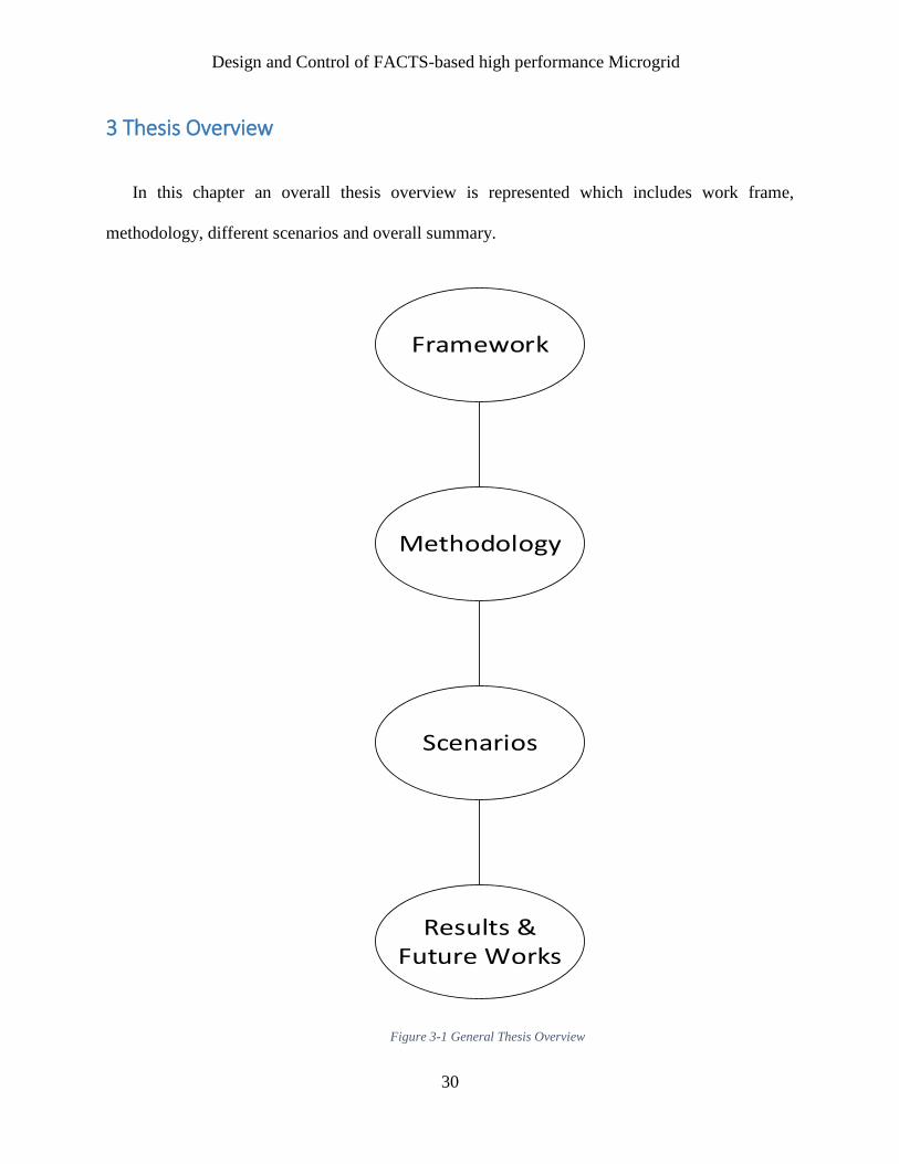
In this chapter an overall thesis overview is represented which includes work frame,
methodology, different scenarios and overall summary.
Framework
Methodology
Scenarios
Results & Future Works
Figure 3-1 General Thesis Overview

Design and Control of FACTS-based high performance Microgrid
31
3.1 Proposed framework
This section gives on review on thesis framework which conclude by review different papers and
journals about microgrid, FACTS, Key Performance Indicators (KPI) of microgrid and modeling
of microgrid. A flowchart on thesis framework is mention below:
Figure 3-2 Thesis Framework

Design and Control of FACTS-based high performance Microgrid
32
3.2 Proposed Methodology
The proposed methodology, with respect to the thesis framework, is as follows:
Microgrid Modelling: Develop model libraries of MEG technologies and identify design and
operation parameters and state variables. This includes voltage profile, power factor, and active
and reactive power, and the associated operational constraints such as voltage limits, line flow
limits, and heat balance constraints.
FACTS modeling: Developing microgrid with FACTS, performance analysis through microgrid
can achieve good reactive power control, voltage and current profile.
Performance KPI Modelling: Detailed key performance indicators (KPI) modelling to evaluate
MEG design, control, operation, installations, and maintenance, in view of lifecycle engineering.
Intelligent heuristic/control System: Design intelligent heuristic/control system for optimized MG
based on Key Performance Indicators and parameters specific to MG installations to meet AC/DC
energy demands, and cogeneration capacities, in view available distributed generation, storage,
and grid inputs. The proposed control will ensure stability to meet acceptable performance of MG
systems.
Integrated Simulation: Design and develop integrated simulation for the MG integration and
infrastructures, with all identified KPIs to evaluate different design and operation scenarios,

Design and Control of FACTS-based high performance Microgrid
33
including the evaluation of the proposed MG control with self-healing and resiliency based on
overall performance, and tuning of the control design.
Figure 3-3 Thesis Methodology

Design and Control of FACTS-based high performance Microgrid
34
3.3 Proposed Microgrid Scenarios
For checking the proposed microgrid design, configuration and verification, different scenarios are
tested that are:
Islanded mode with/ without FACTS with conventional controller
Grid mode with/without FACTS with conventional controller
Islanded mode with/ without FACTS with Intelligent controller
Grid mode with/ without FACTS with Intelligent controller
Figure 3-4 Thesis Scenario

Design and Control of FACTS-based high performance Microgrid
35
4 Modeling of FACTS Devices
4.1 Introduction
This chapter presents systematically review of the most FACTS devices that currently are using
in the industry. Their characteristics, modeling, control, voltage regulation, active and reactive
power flow control, and power quality enhancement are described in this chapter. All FACTS
controllers are modeled in both phasor and time domain, while their steady state operation are
observed.
4.2 FACTS devices
FACTS techniques are divided into four different categories:
1. Series devices
2. Shunt devices
3. Combined Series-Series devices
4. Combined Series-Shunt devices
4.2.1. Series Devices
These devices consist of variable source with main frequencies, sub-synchronous frequencies and
harmonic frequencies. Fundamentally, all series devices inject voltage in series to the system. Main
purpose is to inject voltage in phase that result in reactive power to supply or consume that results
in real power will used.
4.2.2. Shunt Devices
Shunt devices consist of variable impedance, variable source, or combinations of these elements.
Shunt devices inject current into the system at the point of connection. Variable shunt impedance
connected to the line voltage causes a variable current flow and hence represents injection of
Design and Control of FACTS-based high performance Microgrid
36
current into the line. Same as series devices if injected current is in phase reactive power will be
used either way real power will supplied or consumed.
4.2.3. Combined Series-Series Devices
Series-Series devices also known by interline power flow controllers, which are a combination of
separate series devices controlled in a coordinated manner. They have the ability to balance both
real and reactive power flows in the lines
4.2.4. Combined Series-Shunt Devices
Series-Shunt devices are a combination of shunt and series devices, which are controlled in a
coordinated manner. In principle, shunt-series devices inject current into the system with the shunt
part of the controller, and voltage in series in the line with the series part of the controller.
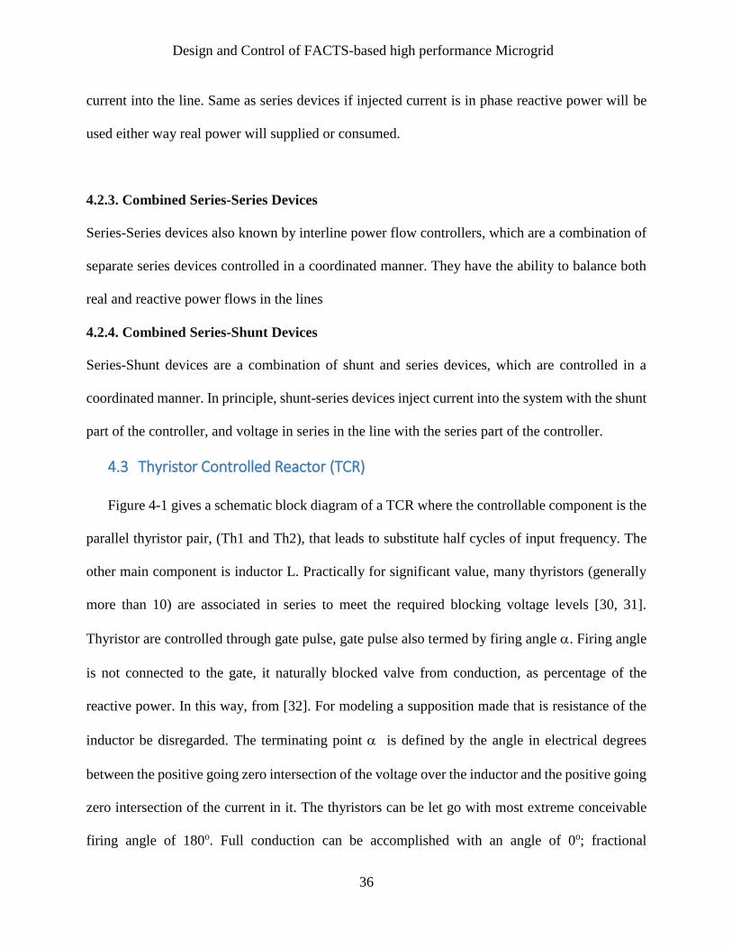
4.3 Thyristor Controlled Reactor (TCR)
Figure 4-1 gives a schematic block diagram of a TCR where the controllable component is the
parallel thyristor pair, (Th1 and Th2), that leads to substitute half cycles of input frequency. The
other main component is inductor L. Practically for significant value, many thyristors (generally
more than 10) are associated in series to meet the required blocking voltage levels [30, 31].
Thyristor are controlled through gate pulse, gate pulse also termed by firing angle . Firing angle
is not connected to the gate, it naturally blocked valve from conduction, as percentage of the
reactive power. In this way, from [32]. For modeling a supposition made that is resistance of the
inductor be disregarded. The terminating point is defined by the angle in electrical degrees
between the positive going zero intersection of the voltage over the inductor and the positive going
zero intersection of the current in it. The thyristors can be let go with most extreme conceivable
firing angle of 180o. Full conduction can be accomplished with an angle of 0o; fractional

Design and Control of FACTS-based high performance Microgrid
37
Figure 4-1 Thyristor Controlled Reactor
conduction can be accomplished with firing angle between 90o and 180o with zero current at 180o.
Firing angle, under 90o are not fit for produce unsymmetrical currents with a high DC part [8].
The fundamental part of TCR current have an aberrant association with firing angle, i.e. reduce in
current result in firing angle increment. That means an increase in the reactor inductance, reducing
both of its reactive power and its current. In Figure 4-2a, the voltage over the TCR inductor and
the current through it are appeared at full conduction. The proportional reactance of the TCR is
equivalent to the inductor reactance. In Figure 4-2b, the present waveform is appeared for a firing
angle of 100o. Just section of the sinusoidal voltage is connected to the inductor, the current and
the voltage are not sinusoidal any longer. The essential part of the current is not as much as that
the present at a 90o firing angle, bringing about an identical reactance of the TCR higher than the
inductor reactance. Figure 4-2c and 4-2d demonstrate the TCR current waveform for a firing angle
of 130o and 150o. The central part of the current through the inductor is little, the equivalent
reactance of the TCR is high, and at 180o it becomes infinite.

Design and Control of FACTS-based high performance Microgrid
38
Figure 4-2 Current waveforms in TCR (a) 90o, 180o (b) 100o (c) 130o (d) 150o [16]
Design and Control of FACTS-based high performance Microgrid
39
4.4 Thyristor Based FACTS Devices
TCR based FACTS devices are Static Var Compensators (SVC) and Thyristor Controlled
Series Capacitor (TCSC).
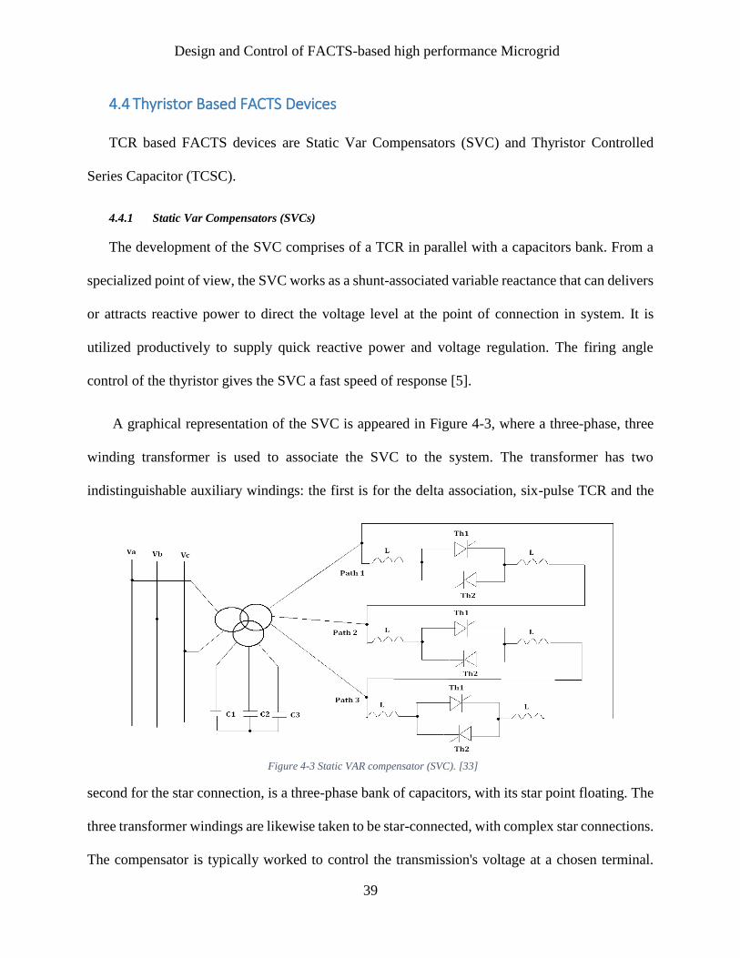
4.4.1 Static Var Compensators (SVCs)
The development of the SVC comprises of a TCR in parallel with a capacitors bank. From a
specialized point of view, the SVC works as a shunt-associated variable reactance that can delivers
or attracts reactive power to direct the voltage level at the point of connection in system. It is
utilized productively to supply quick reactive power and voltage regulation. The firing angle
control of the thyristor gives the SVC a fast speed of response [5].
A graphical representation of the SVC is appeared in Figure 4-3, where a three-phase, three
winding transformer is used to associate the SVC to the system. The transformer has two
indistinguishable auxiliary windings: the first is for the delta association, six-pulse TCR and the
second for the star connection, is a three-phase bank of capacitors, with its star point floating. The
three transformer windings are likewise taken to be star-connected, with complex star connections.
The compensator is typically worked to control the transmission's voltage at a chosen terminal.
Figure 4-3 Static VAR compensator (SVC). [33]

Design and Control of FACTS-based high performance Microgrid
40
Figure 4-4 V-I characteristics. [33]
The V-I characteristics for the SVC, appeared in Figure 4-4, shows that regulation with a given
incline around the nominal voltage can be accomplished in the ordinary operating range that are
characterized by the maximum capacitive and inductive currents of the SVC. While the most
capacitive current lessens linearly and the delivered reactive power is in quadrature with the system
voltage since the SVC goes about as an altered capacitor when the greatest capacitive output is
accomplished. Results in, the voltage regulation ability of the traditional thyristor-controlled static
Var compensator expediently impairs with reducing system voltage [33].
SVCs are likewise utilized for transient first swing, steady state stability and damping changes.
SVC acts like a perfect mid-point compensator until the maximum capacitive induction BCmax is
accomplished. From this point power transmission curve becomes same while its admittance is
BCmax. The steady state stability of power oscillation damping can be acquired by replacing the
output of the SVC between appropriate capacitive and inductive values to change the angular
acceleration and deceleration of the units involved. The purpose is to increase the outputted
electrical power by changing the transmission line voltage (via capacitive vars) when the units
accelerate and reducing the voltage (via inductive vars) when the units decelerate. The powerful
of the SVC in power oscillation damping is a function of the allowed voltage variation.

Design and Control of FACTS-based high performance Microgrid
41
4.4.2 Thyristor Controlled Series Capacitor (TCSC)
A basic TCSC module consists of a TCR in parallel with a capacitor. An actual TCSC
comprises one or more modules. Figure 4-5 shows the layout of one phase of the TCSC installed
in the Slatt substation on USA. The TCSC comprises a capacitor bank inserted in series with the
transmission line, a parallel metal oxide varistor (MOV) to protect the capacitor against over-
voltage and a TCR branch, with a thyristor valve in series with a reactor, in parallel with the
capacitor. Mechanically bypass breakers are provided in parallel with the capacitor bank and in
parallel with the thyristor valve. During normal operation, the bypass switch is open, the bank
disconnect switches (1 and 2) are closed and the circuit breaker is open. When it is required to
disconnect the TCSC, the bypass circuit breaker is switched on first, and then the bypass switch is
switched on. The damping circuit is used to limit the current when the capacitor is switched on or
when the bypass circuit breaker is switched on.
In the fixed-capacitor thyristor-controlled reactor scheme, the degree of series compensation
in the capacitive operating region and the admittance of the TCR are kept below that of the parallel-
connected capacitor is changed with the change in the thyristor conduction angle and also with
TCR current. Minimum series compensation is achieved when the TCR is off. The TCR may be
designed to reach the capability to limit the voltage across the capacitor during faults and other
system contingencies of similar effect.

Design and Control of FACTS-based high performance Microgrid
42
Figure 4-5 Thyristor controlled series capacitor (TCSC). [34]
The overall impedance of the TCSC is given as:
(4.1)
The problem of the last equation is that the harmonic analysis has only been conducted for the
TCR while the analysis of the capacitor charging has been neglected. The total impedance has
LC
LC
TCSCXX
XXX
]2sin)(2[
Figure 4-6 Series compensation vector diagram. [41]

Design and Control of FACTS-based high performance Microgrid
43
been obtained by paralleling the TCR equivalent impedance at the fundamental frequency and the
fixed capacitor. This makes equation (4.1) only valid for the first cycle of the current. The reason
is that after the first cycle has elapsed, the capacitor stores charge, leading to higher steady state
voltages compared to cases when the capacitor charging effect is neglected.
The derivation of the TCSC impedance is started by examining the voltages and currents in
the TCSC under the full range of operating conditions. The basic equation is:
line
TCSC
TCSCI
VZ
)1(
)1( (4.2)
VTCSC (1) is the fundamental frequency voltage across the TCSC model, Iline is the fundamental
frequency line current. The voltage VTCSC (1) is equal to the voltage across the TCSC capacitor and
(4.2) can be written as:
line
capC
TCSCI
IjXZ
)1(
)1(
(4.3)
If the external power network is represented by an idealized current source, as seen from the
TCSC terminals, this current source is equal to the sum of the currents following through the TCSC
capacitor and inductor. The TCSC can then be expressed as:
line
TCRlineC
TCSCI
IIjXZ
)( )1(
)1(
(4.4)
ITCR (1): The fundamental component of the TCR current, can be found by the following:
The line current is, sinsincoscos)cos( tttiline (4.5)

Design and Control of FACTS-based high performance Microgrid
44
The voltage across the TCSC, o
CcapTCR Vdti
Cd
diL
1 (4.6)
Where Vocal is the voltage across the capacitor when the thermistor turns on. In Laplace form
equation (4.5) and (4.6) are
2222sincos
ss
sIline (4.7)
o
CTCRcap CVLCIsI 2 (4.8)
Applying Kirchhoff current low, caplineTCR III (4.9)
Substituting (4.7) and (4.8) into (4.9), and solving for ITCR,
22
2
2222
2
2222
2
))((
1sin
))((cos
o
o
Co
o
o
o
oTCRs
CV
ssss
sI
(4.10)
Where LC
o
12 (4.11)
Substituting the expression for ITCR (1) (The fundamental component of the TCR current) into
(4.4) and assuming Iline = Im cost, leads to the fundamental frequency TCSC equivalent reactance,
as a function of the TCSC firing angle as:
α))(πα))(πω(ωα)((π C
α)))(π(α)(π(CXX CTCSC
tantancos
2sin2
2
2
1
(4.12)
Where

Design and Control of FACTS-based high performance Microgrid
45
ω
ωω 0 ,
LCωo
12 , π
XXC LCC
1 , πX
XC
L
LC2
2
4 ,
LC
LC
LCXX
XXX
Comparing Equations 4.1 and 4.12, the resonant firing angle in the two equations are not the
same. Depending on the ratio between XC and XL, there could be more than one resonant angle for
the TCSC expressed by Equation 4.5.
Figure 4-7 TCSC reactance vs. firing angle α. [41]

Design and Control of FACTS-based high performance Microgrid
46
4.4.2.2 Resonance firing angle:
Examining (4.5), the firing angle that cause resonance is obtained when
0))(cos()cos( resres (4.13)
So , ...., , where n X
X)π(nπα
C
Lres 420
2
1
(4.14)
Although of the effective enhancement on transmittable power, high levels of series
compensation are not typically used. The feasible upper boundary to the limit of series
compensation is about 70 % [53], as more steady state compensation may produce uncontrollable
variations in the power for low alteration in terminal voltages or angles, and large transient currents
and voltages during disturbances at series resonance conditions.

Design and Control of FACTS-based high performance Microgrid
47
4.5 SVS Based-FACTS Device
Among the SVS based Facts devises are the STATCOM, the SSSC and the UPFC.
4.5.1 Static Compensator (STATCOM)
The STATCOM consists of one VSC and its associated shunt-connected transformer. It is the
static form of the rotating synchronous condenser but it supplies or draws reactive power with a
fast rate because there is no moving parts inside it. In principle, it performs the same voltage
regulation function as the SVC but in a more robust manner because, unlike the SVC, its operation
is not impaired by the presence of low voltages. A schematic representation of the STATCOM and
its equivalent circuit are shown in Figure 4-8.
If the energy storage is of suitable rating, the SVS can exchange both active and reactive power
with the network. The active and reactive power, supplied or drawn by the SVS, can be controlled
independently of each other, and any combination of active power, generated or absorbed, with
active power, generated or absorbed, is possible. The active power that the SVS exchanges at its
network terminals with the grid must, of course, be supplied to, or absorbed from, its DC terminals
by the energy storage device. In contrast, the reactive power exchanged is internally generated by
the SVS, without the DC energy storage device playing any significant part in it.
The bi-directional real power exchange capability of the SVS, that is, the ability to absorb
energy from the AC system and deliver it to the DC energy storage device (large storage capacitor,
battery, superconducting magnet) and to reverse this process and deliver power for the AC system
from the energy storage device, makes complete, temporary system support possible. Specifically,
this capability may be used to improve system efficiency and prevent power outages. In addition,

Design and Control of FACTS-based high performance Microgrid
48
Figure 4-8 Static compensator (STATCOM)
in combination with fast reactive power control, dynamic active power exchange is considered as
an extremely powerful method for transient and dynamic stability enhancement.
If the SVS is used strictly for reactive shunt compensation, like a conventional static Var
compensator, then the DC energy storage device can be replaced by a relatively small DC
capacitor, as shown in Figure 4-8. In this case, the steady-state power exchange between the SVS
and the AC system can only be reactive.
When the SVS is applied for reactive power supplying, the inverter itself can maintain the capacitor
charged to the desired voltage level. This is achieved by making lagging in the output voltages of
the inverter and the system voltages by a little angle. In this way, the inverter draws a small amount
of active power from the grid to replenish its internal losses and keep the capacitor voltage at the
required level. The same control procedure can be applied to raise or reduce the capacitor voltage,
and thereby the magnitude of the output voltage of the inverter, for the purpose of controlling the
reactive power generation or absorption. The DC capacitor also has a function of establishing an
energy balance between the input and output during the dynamic changes of the Var output.

Design and Control of FACTS-based high performance Microgrid
49
Figure 4-9 V-I characteristic of STATCOM. [55]
The V-I characteristic of the STATCOM is shown in Figure 4-9. As can be seen, the
STATCOM can act as both capacitive and inductive compensators and it is able to control its
output current independently over the maximum range of the capacitive or inductive of the network
voltage. That is, the STATCOM can produce complete capacitive output current at any grid
voltage level. On the other side, the SVC can supply only output current with reducing system
voltage as calculated by its maximum equivalent capacitive admittance. The STATCOM is,
therefore, superior to the SVC in providing voltage support.

Design and Control of FACTS-based high performance Microgrid
50
Figure 4-10 SSSC Schematic Diagram
4.5.2 Static Series Synchronous Compensator (SSSC)
The Static Synchronous Series Compensator (SSSC) is a series connected FACTS controller
based on VSC and can be viewed as an advanced type of controlled series compensation, just as a
STATCOM is an advanced SVC.
A SSSC has several advantages over a TCSC such as (a) elimination of bulky passive
components (capacitors and reactors), (b) improved technical characteristics (c) symmetric
capability in both inductive and capacitive operating modes (d) the possibility of connecting an
energy source on the DC side to exchange real power with the AC network.
A solid-state synchronous voltage source, consisting of a multi-pulse, voltage-sourced inverter
and a DC capacitor, is shown in series with the transmission line in Figure 4-10.

Design and Control of FACTS-based high performance Microgrid
51
In general, the active and reactive power exchange is controlled by the phase displacement of the
injected voltage with respect to the line current. For example, if the injected voltage is in phase
with the line current, then only active power is exchanged, and if it is in quadrature with the line
current then only reactive power is exchanged.
The series-connected synchronous voltage source is an extremely powerful tool for power flow
control and, it is able to control both the transmission line impedance and angle. Its capability to
exchange active power with the grid makes it very effective in enhancing dynamic stability by
means of alternately inserting a virtual positive and negative damping resistor in series with the
line in sympathy with the angular acceleration and deceleration of the disturbed generators.
The idea of the solid-state synchronous voltage source for series reactive compensation is
based on the rule that the characteristic between the impedance and the frequency of the practically
employed series capacitor, which is different than the filter techniques, has no role in achieving
the required line compensation. The function of the series capacitor is simply to produce an
appropriate voltage at the fundamental AC system frequency in series with the line to partially
cancel the voltage drop developed across the inductive line impedance by the fundamental
component of the line current. So that the resulting total voltage drop of the compensated line
becomes electrically equivalent to that of a shorter line. Therefore, if an AC voltage supply with
fundamental frequency, which has a quadrature lagging relationship to the line current and whose
magnitude is proportional to the line current is injected in series with the line, a series
compensation equivalent to that supplied by a series capacitor at the fundamental frequency is
provided.

Design and Control of FACTS-based high performance Microgrid
52
Mathematically, this voltage source can be defined as follows:
Vn = –jkXI (4.15)
Where Vn is the injected compensating voltage phasor, I is the line current phasor, X is the
series reactive line impedance, and k is the degree of series compensation. For conventional series
compensation, k is defined as XC /X, where XC is the impedance of the series capacitor.
For regular capacitive compensation, the output voltage must lag the line current by 90 degrees,
in order to directly oppose the inductive voltage drop of the line impedance. However, the inverter
output voltage can be reversed by a proper control method to direct it to be leading the line current
by 90 degrees. At this moment, the injected voltage is in phase with the voltage produced across
the inductive line impedance and thus the series compensation has the same effect as if the reactive
line impedance was raised. This capability can be invested to increase the effectiveness of power
oscillation damping and, with sufficient inverter rating; it can be used for fault current limitation.
In practice, however, the semiconductor switches of the inverter are not loss-less, and therefore
the energy stored in the DC capacitor would be used up by the internal losses of the inverter. These
losses can be supplied from the AC system itself by making the inverter voltage lag the line current
by somewhat less than 90 degrees. The typical deviation from 90 degrees is a fraction of a degree.
In this way, the inverter absorbs a small amount of real power from the AC system to replenish its
internal losses and keep the DC capacitor voltage at the desired level. This control procedure can
also be applied to raise or reduce the DC capacitor voltage by making the inverter voltage lag the
line current by an angle smaller or greater than 90 degrees. Thereby, control the magnitude of the
AC output voltage of the inverter and the degree of series compensation.

Design and Control of FACTS-based high performance Microgrid
53
4.6. Unified Power Flow Controller (UPFC)
The UPFC may be considered to be constructed of two VSCs sharing a common capacitor on
their DC side and a unified control system. A simplified schematic representation of the UPFC is
given in Figure 4-11.
The UPFC gives simultaneous control of real and reactive power flow and voltage amplitude
at the UPFC terminals. Additionally, the controller may be adjusted to govern one or more of these
criteria in any combination or to control none of them. This technique allows not only the
combined application of phase angle control with controllable series reactive compensations and
voltage regulation, but also the real-time transition from one selected compensation mode into
another one to deal with particular system contingencies more effectively. For example, series
reactive compensation could be replaced by phase-angle control or vice versa. This may become
essentially important when relatively large numbers of FACTS devices will be applied in
interconnected power grids, and control compatibility and coordination may have to be keep in the
face of devices failures and system changes. The technique would also give considerable operating
flexibility by its inherent adaptability to power system expansions and changes without any
hardware alterations.
The implementation problem of the unrestricted series compensation is simply that of
supplying or absorbing the real power that it exchanges with the AC system at its AC terminals,
to or from the DC input sides of the inverter applied in the solid-state synchronous voltage source.
The implementation in the proposed configuration called unified power flow controller (UPFC)
[55] employs two voltage-sourced inverters operated from a common DC link capacitor; it is

Design and Control of FACTS-based high performance Microgrid
54
shown schematically in Figure 4.11. This arrangement is actually a practical realization of an AC
to DC power converter with independently controllable input and output parameters.
Inverter 2 in the arrangement shown is used to generate voltage VB (t) = VB sin (t-B) at the
fundamental frequency with variable amplitude (0 VB VBmax) and phase angle (0 B 2),
which is added to the AC system terminal voltage by the series connected coupling (or insertion)
transformer. With these stipulations, the inverter output voltage injected in series with the line can
be used for direct voltage control, series compensation, and phase-shift.
The inverter output voltage inserted in series with the line is considered mainly as an AC
voltage source. The current flowing through the injected voltage source is the transmission line
current; it depends on the transmitted electric power and the impedance of the transmission line.
The product of the maximum injected voltage determines the VA rating of the injected voltage
source of Inverter 2 and the maximum line current at which power flow control is still provided.
This total VA consists of two components: the first is the maximum active power, which is
calculated by the maximum line current, and the maximum injected voltage component that is in
phase with this current. The second is the maximum reactive power, which is calculated by the
Figure 4-11 UPFC Schematic diagram

Design and Control of FACTS-based high performance Microgrid
55
maximum line current and the maximum injected voltage component that is in quadrature with
this current.
It is evident that if the unified power flow controller is operated only with the phase angle
reference input, it automatically acts as a perfect phase-shifter. It internally supplies the reactive
power involved in the phase-shifting process and negotiates the necessary real power from the AC
system. Since the active power component is generally smaller than the total VA demand resulting
from phase-shifting, the rating of Inverter 1 would be normally less than that of Inverter 2, unless
the “surplus” rating of Inverter 1 is, again, intentionally utilized for controllable reactive shunt
compensation.

Design and Control of FACTS-based high performance Microgrid
56
4.7 Comparisons of FACTS devices
4.7.1 SVC and STATCOM
SVC STATCOM
An SVC operates as a shunt connected,
controlled reactive admittance.
STATCOM functions as a shunt connected
synchronous voltage source. This difference
accounts for the STATCOM’s superior
functional characteristics, better performance,
and greater application flexibility than those
attainable with an SVC.
In the linear operating range the V-I
characteristics and functional compensation
capability are similar to an SVC
In the linear operating range the V-I
characteristics and functional compensation
capability are similar to an SVC
The maximum attainable compensating current
of the SVC decreases linearly with the AC
voltage.
In the non-linear operating range, the STATCOM
is able to control its output current over the rated
maximum capacitive or inductive range
independently of the AC system voltage.

Design and Control of FACTS-based high performance Microgrid
57
4.7.2 SSSC and TSSC
TSSC TCSC SSSC
TSSC is a impedance type
series compensator
TCSC is a impedance type
series compensator
SSSC is a voltage source
inverter type series
compensator
The compensating voltage
of the TSSC over a given
control range is
proportional to the line
current.
The TCSC can maintain
compensating voltage
with
decreasing line current
over a control range
determined by the current
boosting capability of the
thyristor controlled
reactor.
The SSSC is capable of
internally generating a
controllable compensating
voltage over identical
Inductive and Capacitive
range independently of the
magnitude of the line
current.
An SVC does not have the capability to provide
the active power compensation.
STATCOM can provide active power
compensation in addition to the reactive power
compensation.

Design and Control of FACTS-based high performance Microgrid
58
TSSC cannot exchange
real power with the
transmission line and can
only exchange reactive
power
TCSC cannot exchange
real power with the
transmission line and can
only exchange reactive
power
The SSSC has the
inherent ability to interface
with an external DC power
supply to provide
compensation for the line
resistance by the injection
of real power, as well as
for the line reactance by
the injection of reactive
power for the purpose of
keeping the effective X/R
ratio high, independently
of the degree of series
compensation.
The TSSC uses
conventional thyristors
(with no internal turn-off
capability). These
thyristors are rugged
power semiconductors,
available with the highest
voltage and current
The TCSC uses
conventional thyristors
(with no internal turn-off
capability). These
thyristors are rugged
power semiconductors,
available with the highest
voltage and current
The SSSC uses the GTO
thyristors. These devices
presently have lower
voltage and current ratings
and considerably lower
short-term surge current
ratings. They are suitable
for short term bypass

Design and Control of FACTS-based high performance Microgrid
59
ratings, and they also have
the highest surge current
capability. For short-term
use they also provide
bypass operation to
protect the associated
capacitors during line
faults.
ratings, and they also have
the highest surge current
capability. For short-term
use they also provide
bypass operation to
protect the associated
capacitors during the line
faults.
operation only if the
anticipated line fault
current is relatively low.
Therefore they need
external fast protection
during severe line faults by
an auxiliary conventional
thyristor by pass switch.
TSSC are coupled directly
to the transmission line
and therefore are installed
on the high voltage
platform. The cooling
system and control are
located on the ground with
high voltage insulation
requirements and control
interface.
TCSC are coupled
directly
to the transmission line
and therefore are installed
on the high voltage
platform. The cooling
system and control are
located on the ground
with
high voltage insulation
requirements and control
interface.
The SSSC requires a
coupling transformer rated
at 0.5 p.u. of the total
series compensating
range, and a DC storage
capacitor. However, it is
installed in a building at
ground potential and
operated at a relatively low
voltage. Thus the
installation needs low
voltage insulation for the
cooling system and a
control interface.

Design and Control of FACTS-based high performance Microgrid
60
At rated line current the
loss exhibited by the
TCSC would be 0.5% of
the rated VAr output.
At rated line current the
loss exhibited by the
TCSC would be 0.5% of
the rated VAr output.
At rated line current the
loss exhibited by the
SSSC would be 0.7 to
0.9% of the rated VAr
output

Design and Control of FACTS-based high performance Microgrid
61
5 Microgrid Design & Control
This chapter gives an overview on microgrid configuration, modeling,controlling parameters and
control modes in a microgrid.
5.1 Introduction
Figure 5-1 shows a microgrid architecture which consist of several busses. There is single
connection to the main utility grid called Point of Coupling (PCC). CB1 in figure 1 means
separation device works as an instant switch, which can disconnect grid from the microgrid
whenever any fault occur in the microgrid. AC & DC loads are connected to their respective
busses, these loads are subsidized by local generation. FACTS devices are connected to both load
busses and marked as GP-EE. Corresponding FACTS for AC is MPFC and for DC is GPFC.
Figure 5-1 Mirogrid Architecture

Design and Control of FACTS-based high performance Microgrid
62
The microgrid central controller works as a central control in power systems that controls
distributed generator operations added to the microgrid [54].
5.2 Controlling in Microgrid
Main objective for microgrid is to inject or absorbed energy from the grid, control the power
flows, and balance the voltage profile in grid. Generators, small storage devices, and loads are to
be controlled to achieve these objectives. To connect distributed sources such as Wind turbines,
PV, fuel cells or storage devices power electronic devices interfaces is used within the micro-grid
[54]. According to [56] micro-grids are divided into different type of classes based on their
controlling topology. Depending on their topology, microgrid control can be divided into three
classes [55].
5.2.1 Simple Class or Virtual ‘Prime Mover’
In this class, a central controller records the microgrid’s state variables and provides
information to all local distributed generators. This topology makes one central virtual power
supply which control all system generation and distribution behavior. Central control is based on
telecommunication system that provides sub system access. Whole microgrid system shutdown if
communication to the central control breaks. Also there are limited numbers of distributed
generators channels are available. If all channels are full the central controller has to be replaced.

Design and Control of FACTS-based high performance Microgrid
63
5.2.2 Master Class or Physical ‘Prime Mover’
In this class a separate and bigger central controller is installed within the microgrid. Mainly a
generator or an energy storage device. Central controller works as a “master” to control all transient
flows and balance the voltage profile in microgrid with utility grid (islanded connection). The other
sources works as a “slave” that injects current to the microgrid buses. As one large central control
all sources, it has some disadvantages too, as all control depends on one master controller, system
reliability also depends on master unit. In future if any loads needed to increase in the microgrid
results in resizing of central controller to adopt load changes.
5.2.3 Peer to Peer or Distributed Control
In this class each units provides automatic variations for local variables such as power flow or
voltage magnitude. This local control accommodates transient or local behavior. Each controllers
in microgrid has to ensure enough computational frequency to be able to secure stable operation
in the microgrid. For ensuring frequency and voltage stability an ‘intelligent’ local controller is
provided at each generation source location. On islanded connection mode, power flow in
microgrid has to balance loads and sources without voltage variations. In the Table 5.1, the
different methods of controlling microgrid and their characteristics are described.

Design and Control of FACTS-based high performance Microgrid
64
Table 5-1 Microgrid control method classifications [56]
Simple or
“Virtual Prime
Mover”
Master Control or
Physical “Primer
Mover”
Peer to Peer
Control
or Distributed
Control
Specific
Characteristics
All sources acts as
one
central power plant
One “Master”
generator control the
voltage level and the
“Slave” generators
works as a current
sources.
Each
sources have
their own local
controller that
controls
frequency,
voltage
stability.
Common
Characteristics
Several sources are injecting power on several loads
in multiple locations.
All the sources are connected to the microgrid bus.
Every event are detected and response are controlled

Design and Control of FACTS-based high performance Microgrid
65
5.3 DER control
There are two main functions of DER control are
(i) real- and reactive power control in the grid-connected mode
(ii) Frequency and voltage regulation of microgrid in islanded mode
5.4. Grid-Connected-Mode DER Control
Grid connected mode DER control works with the frequency and magnitude of system voltages,
which are provided by the grid controlled by utility. The main task in grid connected mode is to
control active and reactive power exchange within the local networks. For regulation of output
powers it can use current or voltage mode control technique. In Figure 5-2 defines a simplified
schematic diagram of a voltage-controlled DER system, DER system is connected with the grid
through a three phase inductor L and Voltage-Sourced Converter (VSC). In voltage mode control
strategy, the output active and reactive powers (Po, Qo) are controlled through phase-angle and
magnitude of the VSC on AC terminal voltage vtabc [57].
Figure 5-2 diagram of a grid-connected DER system with voltage mode [10]

Design and Control of FACTS-based high performance Microgrid
66
Hence it conclude as every phase of voltage can added by VSC, (v∗ tabc) is calculated from
shifting the phase-angle and scaling the amplitude of the substitute phase of vsabc [57].
For the voltage-mode and current-mode control techniques of Figure 5-2 and 5-3 is used. The DER
has been assumed to be ready to be dispatched, output real and reactive powers can be
controlled by the set points Pore f and Qore f (which, in turn, are determined by the MCC). By
contrast, the output powers of a non-dispatchable DER system are commonly the by-products of
an optimal operating condition. For example, a PV system normally operates in the Maximum
Power- Point Tracking (MPPT) mode [58], that is, it extracts the maximum possible power from
its solar panels.
Figure 5-3 Schematic diagram of a grid-connected DER system with current mode [57]

Design and Control of FACTS-based high performance Microgrid
67
Figure 5-4 Schematic diagram of a grid-connected non-dispatchable DER system [57]
Figure 5-4 illustrates a simplified schematic diagram of a non-dispatchable DER system (e.g.,
a PV system [58]) in which the DER has been modeled by a dc voltage source whose voltage,
vdc, is related to its current, iDER, through a v-i characteristic. As Figure 5-4 illustrates, the
kernel of the control system that is the real- and reactive-power control scheme (of Figure 5-3) by
which Po and Qo can be controlled independently.

Design and Control of FACTS-based high performance Microgrid
68
6 Control Design of FACTS-Based Microgrid
This chapter gives an overview on modeling and design of microgird with FACTS devices.
Also including the equations involved with different generation units which are PV, gas turbines,
wind turbines, fuel cells and batteries.
The proposed microgrid design has modeled with FACTS devices on both AC and DC loads
busses. Modulated power filter compensators (MPFC) are used at AC side to improve voltage
stability, reduce harmonic current and power loss. Also green plug filter compensators (GPFC) are
added at the DC-side FACTS device to stabilize DC voltage performance. Multi-loop error driven
control strategies are configured for the converters to properly benefit the AC and DC buses with
their FACTS. Intelligent algorithm using genetic algorithm is used for self-tune the converter and
FACTS controllers gain.
6.1 Hybrid AC/DC Microgrid Design
The design of the hybrid AC/DC microgrid system is pictured in Figure 6-1, a connected meshed
microgrid with different AC and DC sources and loads are connected to their alternating sub grids.
Also these loads are connected to utility bus with hybrid local loads. The AC and DC grid is linked
to utility sub grid with 10km and 5km feeder respectively. At AC sub grid a step up transformer is
used to boost up AC and with DC sub grid a step down transformer is used. AC and DC both grid
are also connected with AC/DC, DC/AC converter and inverter to exchange a hybrid connection
in the grid. All parameters for microgrid loads, FACTS, DER and other sources specifications are
mentioned in the Appendix section.

Design and Control of FACTS-based high performance Microgrid
69
Energy
Storage
FC
H2
Micro
Gas
turbine
T4
Vg
1.6/0.6 kV
2 MVA
300 μF
25 kV
T3
Vg1 Vg2
Wind
Energy
138/25 kV
5 MVA
VS
AC Grid
T1
T5
T2
Multi Loop
Controller
Multi Loop
Controller
MPFC
Multi Loop
Controller
V1
VdcVd1
25/4.16 kV
2 MVA
25/0.6 kV
2 MVA
25/1.6 kV
2 MVA
Converter 1
Controller
Converter 2
Controller
Vg1 Ig1Vdc
Vac1
Vac1
Vd1
Id1
Hybrid AC
Load 2 DC Loads
Hybrid AC
Load 1
5 km
Feeder
10 km
Feeder
10 km
Feeder
PV
Array
Battery
MPFC
GPFC
CB
V1
I1
Scheme 1
Scheme 2 Converter 1
Converter 2
VL
Gate 2
Gate 1
~
=
~
=
Boost
Chopper
Boost
Chopper
Microgrid
Point of
Coupling
(MPC)
Figure 6-1 Hybrid AC/DC microgrid

Design and Control of FACTS-based high performance Microgrid
70
Figure 6-2 Full schematic of AC/DC microgrid
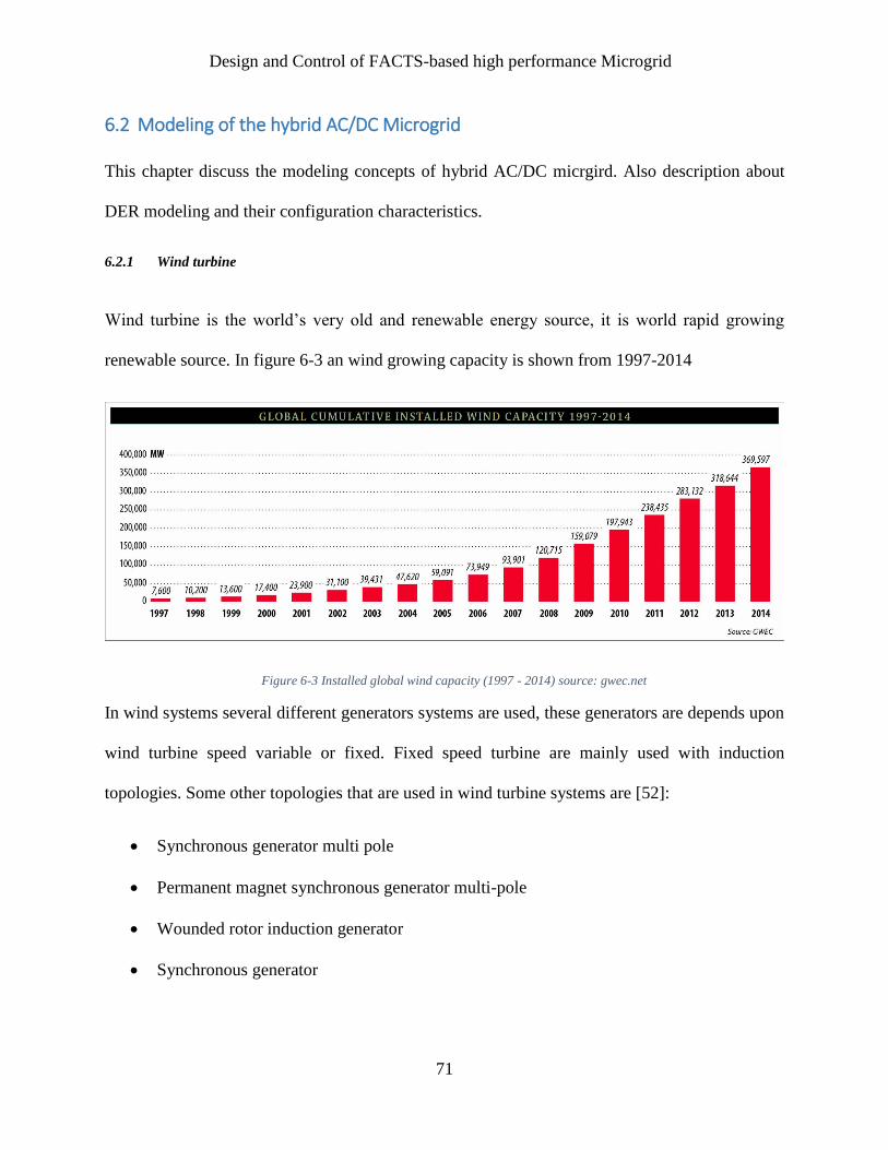
Design and Control of FACTS-based high performance Microgrid
71
6.2 Modeling of the hybrid AC/DC Microgrid
This chapter discuss the modeling concepts of hybrid AC/DC micrgird. Also description about
DER modeling and their configuration characteristics.
6.2.1 Wind turbine
Wind turbine is the world’s very old and renewable energy source, it is world rapid growing
renewable source. In figure 6-3 an wind growing capacity is shown from 1997-2014
Figure 6-3 Installed global wind capacity (1997 - 2014) source: gwec.net
In wind systems several different generators systems are used, these generators are depends upon
wind turbine speed variable or fixed. Fixed speed turbine are mainly used with induction
topologies. Some other topologies that are used in wind turbine systems are [52]:
Synchronous generator multi pole
Permanent magnet synchronous generator multi-pole
Wounded rotor induction generator
Synchronous generator
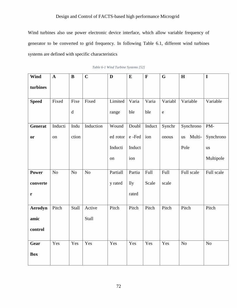
Design and Control of FACTS-based high performance Microgrid
72
Wind turbines also use power electronic device interface, which allow variable frequency of
generator to be converted to grid frequency. In following Table 6.1, different wind turbines
systems are defined with specific characteristics
Table 6-1 Wind Turbine Systems [52]
Wind
turbines
A B C D E F G H I
Speed Fixed Fixe
d
Fixed Limited
range
Varia
ble
Varia
ble
Variabl
e
Variable Variable
Generat
or
Inducti
on
Indu
ction
Induction Wound
ed rotor
Inducti
on
Doubl
e -Fed
Induct
ion
Induct
ion
Synchr
onous
Synchrono
us Multi-
Pole
PM-
Synchrono
us
Multipole
Power
converte
r
No No No Partiall
y rated
Partia
lly
rated
Full
Scale
Full
scale
Full scale Full scale
Aerodyn
amic
control
Pitch Stall Active
Stall
Pitch Pitch Pitch Pitch Pitch Pitch
Gear
Box
Yes Yes Yes Yes Yes Yes Yes No No

Design and Control of FACTS-based high performance Microgrid
73
A fixed speed wind turbine is considered in this proposed design, shown in figure 6-4
G
Wind
Turbine Rotor
Gear Box
Squirrel Cage
Induction
Generator
Soft Starter
Compensation
Capacitor
Figure 6-4 Wind turbine with fixed speed
From [23] an equation for output is derived as:
𝑃𝑚 = 0.5𝜌𝐴𝐶𝑝(𝜆, 𝛽)𝑉𝑤3 (6.1)
Where
ρ = air density,
A = rotor swept area,
Vw = wind speed,
Cp (λ, β) = the power coefficient with function of tip speed ratio λ and pitch angle β.
Wind turbine output power depends on Cp which is a power coefficient under constant wind
speed. For maximum power from wind turbine, Cp have to control for optimum values of turbine
rotating speed and pitch angle. Standard active controller is the controller of machine. Wind
turbine is controlled with a soft starter and bank of capacitors in the grid.

Design and Control of FACTS-based high performance Microgrid
74
6.2.2 Photovoltaic
Photovoltaic (PV) generation usage are increasing significantly, due to their noise less and small
size, PVs becoming famous day by day. In figure 6-5, an overview of current installed and
forecasted PV solar capacity are shown.
A series and parallel combination of PV cells constitute a PV array. The simplified equivalent
circuit of the PV array is used where the output voltage is a function of the output current while
the current is a function of load current, ambient temperature and radiation level [47]. The current
and voltage equation of the PV is defined by [47]:
𝑉𝑃𝑉 =𝐴𝑘𝑇𝑐
𝑒𝐿𝑛 (
𝐼𝑝ℎ+𝐼𝑜−𝐼𝐶
𝐼𝑜) − 𝑅𝑆𝐼𝐶 (6.2)
where A is a constant value for curve fitting, e is the electron charge (1.602×10⁻¹⁹ C), k is
Boltzmann constant (1.38×10⁻²³ J/K), Ic is the output current of PV cell, Iph is the photocurrent
Figure 6-5 Recorded and Forecasted PV Capacity. Source: evwind.es

Design and Control of FACTS-based high performance Microgrid
75
(1 A), Io is the diode reverse saturation current (0.2 mA), Rs is the series resistance of PV cell
(1mΩ), VPV is the output voltage of PV cell and Tc is the PV cell reference temperature (25◦ C).
The output boost chopper controls the voltage Vout across the capacitor.
6.2.3 Fuel Cell
Fuel Cells are emerging as an attractive power supply source for applications such as distributed
generation and small grids because of their high efficiency and high reliability [48]. A typical
PEMFC (proton exchange membrane fuel cell) are connected in series/parallel for desired output
rating. For regulating Fuel cell output DC voltage a boost chopper is used. An overall circuitry is
detailed in following figure.
V(i)
+
-
Vc
+
-
I
Boost Chopper
6.2.4 Energy Storage Batteries
Common energy storage lead acid batteries are used. These batteries are low cost, have fast
response and have prolong half-life. These batteries power capacity are based on the size and
geometry of electrodes. A standard 240 V battery is selected for current microgrid model.

Design and Control of FACTS-based high performance Microgrid
76
6.2.5 AC and DC loads
As viewed in figure 6-1, there are following loads:
Hybrid AC load 1, that are resistive load consist of an induction motor with a nonlinear
load which is combination of harmonic and unbalance load.
Hybrid AC load 2, consist of different ratings but same loads as AC load 1.
DC loads, consist of resistive load connected with series DC motor.
6.2.6 FACTS Devices
Two types of FACTS devices used in current AC/DC microgrid
Modulated Power Filter Compensator (MPFC):
The circuitry diagram shown in Figure 6-7, which is consists of one series and two shunt capacitor
banks including a tuned arm power filter. The output path for shunt capacitors is created by the
diode rectifier having resistance (Rf) and inductance (Lf) for tuned arm filter at the rectifier’s DC
length [49, 50]. Two IGBT switches (Sa and Sb) are controlled by two adjacent switching signals
(P1 and P2), as viewed in figure 6-6. These signals are created by dynamic multi-loop error driven
in PID controller. Then feed to the PWM switching circuit to control IGBT switches.
The MPFC can be substituted in following cases;
Case 1: If P1 is high and then P2 is low, the resistor and inductor will be connected into the circuit
as a tuned arm filter.

Design and Control of FACTS-based high performance Microgrid
77
Case 2: If P1 is low and P2 is high, the resistor and inductor of the arm filter will be fully shorted
and the combined shunt and series capacitors will provide the required shunt and series capacitive
compensation to the AC distribution system.
Green Plug Filter Compensator (GPFC):
The main reason to adding FACTS at the DC side of microgrid is to enhance DC performance and
to stabilize buses voltages. GPFC compensation block diagram can be viewed in figure 6-8,
introducing a switching signal through PID controller. GPFC will regulate DC bus voltage and
decrease inrush current sampling transients and also for FC and PV nonlinear Volt-Ampere
characteristics.

Design and Control of FACTS-based high performance Microgrid
78
Sa
Sb Rf
Lf
Cs
Cf1 Cf2
+ -
P2
P1
Bridge
Rectifier
PID
Controller
Loop Error
Figure 6-6 Modulated Power Filter Scheme
S0
RS LS
Cs
+ -
P0
Bridge
Rectifier
VdcVd1
PID
controller
Loop Error
Figure 6-7 Green Plug Filter Compensator Scheme

Design and Control of FACTS-based high performance Microgrid
79
6.3 Control Design
For controlling all FACTS device PID controller are used, that can control whole microgrid
performance. PID controller is a set of three controllers by names are proportional, integral,
derivative controller. An optimal method for tuning PID controller which includes time varying
delays is considered in current microgrid scheme. PID controller’s parameters are considered as
function of the time constant.
6.3.1 PID Controller
PID controller is mainly used in many industrial application because of its easy control strategy,
cheap cost and simple design. But mainly the performance of PID controller is very bad for highly
nonlinear and uncontrolled loads schemes. In PID, proportional controller uses ‘portion’ of system
error to control whole system output, Integral controller’s output is proportional to the length of
time error present in the system, lastly derivative controller is proportional to the rate at which
error changes in the system. By using proportional controller an offset of error is introduced in the
system, by integral controller this offset error is removed from the system and by derivative
controller overshoot in the system is reduced. PID control scheme for current control model using
time varying dependent is described as:
∆u(t) = 𝑘𝑐𝑇𝑠𝑘𝑐𝑇𝑠
𝑇𝐼e(t) − kc(∆ +
𝑇𝐷
𝑇𝑠∆2)y(t), t = 0.1, 2,…………………………………………….(6.3)

Design and Control of FACTS-based high performance Microgrid
80
Where
u(t) = The control variable,
e(t) = The control error signal,
e(t)=yref(t)−y(t)
,yref(t) = The reference value,
y(t) = The system output.
kc, TI and TD are the proportional gain, integral
and the derivative time, respectively.
For controlling FACTS devices and other converter following are controlled through PID are:
MPFC
GPFC
AC/ DC converter
6.3.2 MPFC controlling:
For controlling modulated power filter compensator a multi-loop error driven dynamic controller
is added in coordinate with PWM switching. The multi-loop global error (e1) is the sum of the
multi-loop individual errors including synthesis dynamic power loops, voltage stability and current
limiting. Error vector (eV, eI, eP) and global error (e1) are evaluated by the following equations:
𝒆𝑽𝟏=
𝑽𝟏𝒓𝒆𝒇−𝑽𝟏(𝟏
𝟏+𝑺𝑻𝟏)
𝑽𝟏𝒃𝒂𝒔𝒆 (6.4)
𝒆𝑰𝟏=
𝑰𝟏𝒓𝒆𝒇−𝑰𝟏(𝟏
𝟏+𝑺𝑻𝟏)
𝑰𝟏𝒃𝒂𝒔𝒆 (6.5)

Design and Control of FACTS-based high performance Microgrid
81
𝒆𝑷𝟏= (
𝑽𝟏
𝑽𝟏𝒃𝒂𝒔𝒆×
𝑰𝟏
𝑰𝑳𝒃𝒂𝒔𝒆) − (
𝑽𝟏
𝑽𝟏𝒃𝒂𝒔𝒆×
𝑰𝟏
𝑰𝟏𝒃𝒂𝒔𝒆) (
𝟏
𝟏+𝑺𝑻𝟐) (6.6)
𝒆𝟏 = 𝜸𝑽𝟏|𝒆𝑽𝟏
| + 𝜸𝑰𝟏|𝒆𝑰𝟏
| + 𝜸𝑷𝟏|𝒆𝑷𝟏
| (6.7)
The output of the PWM generator is a series of pulses with varying duty cycles and constant
frequency. MPFC scheme for voltage controlling in the system can be defined by:
𝑽𝑪𝟏(𝒕) = 𝑲𝑷𝟏𝒆𝟏(𝒕) + 𝑲𝑰𝟏 ∫ 𝒆𝟏(𝒕)𝒅𝒕𝒕
𝟎+ 𝑲𝒅𝟏
𝒅(𝒆𝟏(𝒕))
𝒅𝒕 (6.8)
The filter arm modulation is achieved through two complementary pulses (Sa and Sb) governed
by PWM. These signal are controlled through gate pulse which is dependent of switching
frequency (𝑓𝑠𝑤).
𝑇𝑆𝑤 =1
𝑓𝑠𝑤= 𝑇𝑜𝑛 + 𝑇𝑜𝑓𝑓 (6.8)
Where
fsw = The switching frequency and 0<Ton<Tsw

Design and Control of FACTS-based high performance Microgrid
82
Figure 6-8 MPFC multi-loop error driven scheme
6.3.3 GPFC controlling The GPFC control scheme is handled through voltage and decoupled current part of DC bus, shown
in figure 6-9. Following are multi-loop error equations:
𝒆𝟑 = 𝜸𝑽𝒅𝟏|𝒆𝑽𝒅𝟏
| + 𝜸𝑰𝒅𝟏|𝒆𝑰𝒅𝟏
| + 𝜸𝑷𝒅𝟏|𝒆𝑷𝒅𝟏
| (6.9)
𝒆𝑽𝒅𝟏=
𝑽𝒅𝟏𝒓𝒆𝒇−𝑽𝒅𝟏(𝟏
𝟏+𝑺𝑻𝟓)
𝑽𝒅𝟏𝒃𝒂𝒔𝒆 (6.10)
𝒆𝑰𝒅𝟏=
𝑰𝒅𝟏
𝑰𝒅𝟏𝒃𝒂𝒔𝒆(
𝟏
𝟏+𝑺𝑻𝟓) (𝟏 −
1
1+𝑆𝑇6) (6.11)
𝑒𝑃𝑑1= (
𝑉𝑑1
𝑉𝑑1𝑏𝑎𝑠𝑒×
𝐼𝑑1
𝐼𝑑1𝑏𝑎𝑠𝑒) (1 −
1
1+𝑆𝑇6) (6.12)
GPFC scheme in the time domain for the controlling PID controller through PWM has following
equations:

Design and Control of FACTS-based high performance Microgrid
83
𝑉𝐶3(𝑡) = 𝐾𝑃3𝑒3(𝑡) + 𝐾𝐼3 ∫ 𝑒3(𝑡)𝑑𝑡𝑡
0+ 𝐾𝑑3
𝑑(𝑒3(𝑡))
𝑑𝑡 (6.13)
Vd1-
ƔPd1
+
Id1
+
-
+
-
ƔVd1
ƔId1
Vd1ref
+
++
PWM
LimiterPID
tuning
Controller
Voltage Stabilization Loop
Current ripple Limiting Loop
fsw
baseV
1
d1
baseI
1
d1
e3 SeVC3
eVd1
ePd1
eId1
51
1
ST
51
1
ST
61
1
ST
61
1
ST
Figure 6-9 GPFC multi-loop error regulating scheme
6.3.4 AC/DC Converter controlling:
AC/DC control through by changing the pulses of duty cycle that used to change on/off state. By
controlling that pulse DC output voltage of controller is stabilize.
For tunning and optimizing all controller that effect overall microgrid performance all controllers’
gains are objected in optimization problem.
MPFC PID controller gains (Kp1, Ki1and Kd1),
GPFC PID controller gains (Kp2, Ki2 and Kd2),
AC/DC converter 1 controller gains (Kp3, Ki3 and Kd3)
In current microgird model shown in figure 6-1, two MPFC, two AC/DC converter and one GPFC
are used. To minimize the sum of all controllers’ errors:
𝐽 = 𝑒1 + 𝑒2 + 𝑒3 + 𝑒4 + 𝑒5 (6.14)

Design and Control of FACTS-based high performance Microgrid
84
Current system has following Key Performance Indicators (KPI), by optimizing these KPI whole
microgrid performance are optimized:
1) The voltage stabilizations at the AC and DC buses:
Vmin ≤ Vbus≤ Vmax (6.15)
2) The feeder current capacity limit:
0 ≤ 𝐼𝐹𝑒𝑒𝑑𝑒𝑟 ≤ 𝐼𝑚𝑎𝑥 (6.16)
3) The power factor at the AC buses:
𝑃𝐹𝐴𝐶 ≥ 𝑃𝐹𝐴𝐶𝑟𝑒𝑓 (6.17)
4) The total harmonic distortion of the voltage (THDv) at the AC buses:
THDv < THDv,max (6.18)
The THD can be calculated by: 𝑇𝐻𝐷𝑣 =√∑ 𝑉ℎ
2𝑛ℎ=2
𝑉1 (6.19)
5) the total harmonic distortion of the current (THDi) at the AC buses:
THDi < THDi,max (6.20)
𝑇𝐻𝐷𝑖 =√∑ 𝐼ℎ
2𝑛ℎ=2
𝐼1 (6.21)
The power balance equation of overall hybrid AC/DC microgrid is as follows:
𝑃𝑔𝐴𝐶+ 𝑃𝑔𝐷𝐶
± 𝑃𝑆 = 𝑃𝐿𝐴𝐶+ 𝑃𝐿𝐷𝐶
+ 𝑃𝐿𝑜𝑠𝑠𝑒𝑠
Where
𝑃𝑔𝐴𝐶: Generated real power of the AC sources (Micro gas turbine and wind turbine)
𝑃𝑔𝐷𝐶: Generated power of the DC sources (PV, fuel cells, battery)
𝑃𝑆 : Injected power from/to the utility grid.

Design and Control of FACTS-based high performance Microgrid
85
6.3.5 Genetic Algorithms
The genetic algorithms (GAs); is used for optimizing above KPI. GA is inspired by Darwin’s
reproduction and survival of fittest individual. GA searches for the fittest individual from a group
of solutions known by population. These solution is corresponds to mutation, crossover and
selection operators to find the best solution. The fitness function estimate the possibility of every
individual. The selection operator selects the fittest individual. For variety and different scenarios
crossover and mutation operators are used. Starting values or chromosomes are randomly
generated and selected for the initial population. The crossover
and mutation probability are constant from start till end of the
function. The size of population is remain fixed throughout the
process, with fittest chromosome in each generation is saved.
Then saved chromosome is directly moved to the next step to
be evaluate again until expected population is converged. The
whole algorithm ends when the population consist of the fit or
the optimal solution [61] – [63]. The optimal solution are
presented a set of parameters, these parameters are known as
‘gene’. These genes are formed together to form a string called
a chromosome.
6.3.6 Continuous-Parameter GA
In the fitness function parameters are continuous, these function are represented as floating
numbers. The fittest possible individual is selected by random generation considering the highest
probability is selected. If P1 and P2 are chosen to perform crossover, the resulting crossover
equation are to be:
Define Parameters fitness function
Create population
Evaluate fitness
Select mate
Perform crossover
Mutate
Test convergence
Stop
Figure 6-10 Overview of Genetic Algorithm

Design and Control of FACTS-based high performance Microgrid
86
P`1 = r.P1 + (1-r).P2 (6.22)
P`2 = (1-r).P1 + r.P2 (6.23)
Where
r = random number between 0 and 1.
Non-uniform mutation is defined as follows, if an element Pk of a parent P is selected for
mutation, the result would be:
1)()(
)()(
is digit random a if genfPLBP
0 is digit random a if genf PUBPP
kk
kk
k (6.24)
Where
UB and LB are the upper and lower bounds of the Pk ,
gen is the current generation.
b
gen
genrgenf ))
max1.(()( (6.25)
r = random number in the range [0, 1],
genmax = The maximum number of generation,
b = The shape parameter to calculate the non-uniformity.

Design and Control of FACTS-based high performance Microgrid
87
6.3.7 Self Tunning of PID Controller Using Genetic Algorithm
Continuous genetic algorithm is used for current optimization problem. Self tunning of PID
controller is done through genetic algorithms that simulated in MATLAB/ Simulink using GA
toolbox [28]. It uses a low probability scheme usually in range of 0.001% to 0.01%.
The function of mutation is to ensure that the probability for searching never becomes to zero and
to works as safety wall to safe best genetic solution that lost in corresponding process. There are
three option for mutation operator as it has multi non-uniformity distribution.
The total number of mutations, with a probability of around 0.1%.
The maximum number of generations.
The shape of the distribution.
The genetic algorithm was initialized with a population of 30 and iterated for 50 generations. The
bounds of the genetic algorithm reduced to a smaller range of numbers.
The genetic algorithm code simulated the Simulink file, which includes the plant, and the
RLS estimator. GA takes parameter estimates and start performing search through current values.
GA optimization parameter are shown in Table 6-2. After possible solution GA updates all
specified PID controller gains to get a stable system output. Through discrete poles values (real
and imaginary) system stability is examined.

Design and Control of FACTS-based high performance Microgrid
88
Table 6-2 GA optimization parameters
Genetic Algorithm Parameter Value
Population size 30
Maximum generation 50
Probability of crossover 70 %
Probability of mutation 0.5 %
Convergence tolerance 1X 10⁻⁶
6.3.8 Intelligent Controlling
Intelligent controlling means to make controller self-reliable, self-adjustable and self-tuned.
Making a controller an intelligent controllers is to impose the controller with humanlike behavior.
In current controlling strategy fuzzy logic algorithm is used. Fuzzy logic is a set of fuzzy values
that clearly defined within boundary. These sets form a degree of membership. This membership
Function (MF) shows every point as an input criterion to a membership values (0 and 1). In fuzzy
logic controller the dynamic behavior of system is configured through defined set of rules. These
rules in the form of
IF (a set of condition are matched, that added with fuzzy terms) THEN (a set of results can
occur in the system)

Design and Control of FACTS-based high performance Microgrid
89
6.3.9 Integration of GA with Fuzzy
Integeration of GA with Fuzzy logic Algorithm will enahnce the dynamic response of the
microgrid, that are done through controlling the PID gains. Firstly all possible best KPI values of
microgrid are inputted in the GA to calculate an initial generation. By inspecting overall microgrid
performance using random controllers’ gains, best response of controller gains and KPI values are
obtained. These values are used to self-tuned fuzzy system. These values are integrating in fuzzy
system, figure 6-11 gives an overview of whole controlling of fuzzy integrating with PID and GA.
Figure 6-11 GA with Fuzzy

Design and Control of FACTS-based high performance Microgrid
90
In Figure 6-12, gives an overview of fuzzy system. It has KPI’s of microgrid as input to the system
and PID controllers gains as its output. After tuning and updating whole fuzzy system, best tuned
controller gains are selected for the PID controller. This microgrid performance is more intelligent
and reliable by using fuzzy gains for PID controller.
GA
optimization
Fuzzy PID Gains
(Kp, Ki, Kd)
Kp, Ki, KdKPI’s
Figure 6-12 Fuzzy system tuning

Design and Control of FACTS-based high performance Microgrid
91
6.4 Matlab Simulation Block View
Figure 6-13 Simulink Block view Of Hybird AC/DC microgrid

Design and Control of FACTS-based high performance Microgrid
92
7 Simulation Results and Discussions
In this chapter simulation results is defined. Different scenarios are discussed with several
parameters and configurations. These scenarios are consisted of
Grid connected mode with FACTS using PID/Conventional Controller
Islanded mode with FACTS using PID/Conventional Controller
Grid connected mode with FACTS using Fuzzy Controller
Islanded mode with FACTS using Fuzzy Controller
Each scenarios are compared with FACTS/ Without FACTS comparison.
7.1 Grid Mode With/Without FACTS using PID controller
In this mode Utility grid is still connected to the microgrid. Voltage, Line current, Reactive and
power and power factor through all busses (Vs, VL, Vg, and V1) are monitored. Conventional PID
controller is connected to control all FACTS devices and converters.
Figure 7-1 Voltage, Current, Reactive power and Power Factor at AC bus (VS)

Design and Control of FACTS-based high performance Microgrid
93
Figure 7-2 Voltage, Current, Reactive power and Power Factor at AC bus (V1)
Figure 7-3 Voltage, Current, Reactive power and Power Factor at AC bus (Vg)
Figure 7-4 Voltage, Current and power at DC bus (Vdc)
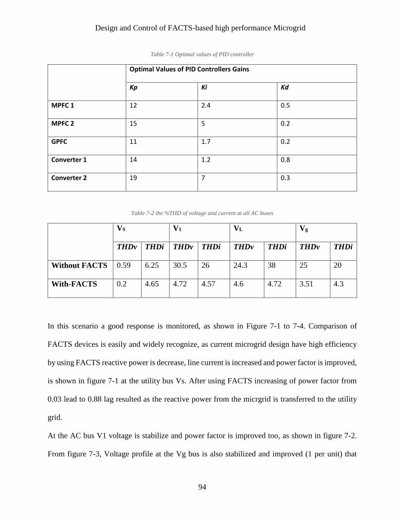
Design and Control of FACTS-based high performance Microgrid
94
Table 7-1 Optimal values of PID controller
Optimal Values of PID Controllers Gains
Kp Ki Kd
MPFC 1 12 2.4 0.5
MPFC 2 15 5 0.2
GPFC 11 1.7 0.2
Converter 1 14 1.2 0.8
Converter 2 19 7 0.3
Table 7-2 the %THD of voltage and current at all AC buses
VS V1 VL Vg
THDv THDi THDv THDi THDv THDi THDv THDi
Without FACTS 0.59 6.25 30.5 26 24.3 38 25 20
With-FACTS 0.2 4.65 4.72 4.57 4.6 4.72 3.51 4.3
In this scenario a good response is monitored, as shown in Figure 7-1 to 7-4. Comparison of
FACTS devices is easily and widely recognize, as current microgrid design have high efficiency
by using FACTS reactive power is decrease, line current is increased and power factor is improved,
is shown in figure 7-1 at the utility bus Vs. After using FACTS increasing of power factor from
0.03 lead to 0.88 lag resulted as the reactive power from the micrgrid is transferred to the utility
grid.
At the AC bus V1 voltage is stabilize and power factor is improved too, as shown in figure 7-2.
From figure 7-3, Voltage profile at the Vg bus is also stabilized and improved (1 per unit) that

Design and Control of FACTS-based high performance Microgrid
95
shows reactive power is fully compensated by FACTS. At the DC bus, voltage, current and power
is stabilize and definite comparison of FACTS can be seen. In Table 7-2, THD for all busses are
evaluated, this table shows the reduction in harmonic orders of microgrid voltage and current.
Using FACTS all THD values for voltage and currents are improved and controlled to ensure them
in within limits.

Design and Control of FACTS-based high performance Microgrid
96
7.2 Islanded Mode With/Without FACTS using PID controller
In this scenario, utility grid is disconnected from the microgrid and connected DER uses to
compensate loads needs. Control scheme is modeled with conventional PID controller.
Figure 7-5 reactive power and Power factors at Vg buses
Figure 7-6 Voltage and power at Vd bus

Design and Control of FACTS-based high performance Microgrid
97
Figure 7-7 Voltage, Reactive power and Power factors at V1 buses
Table 7-3 Optimal values of PID controller
Optimal Values of PID Controllers Gains
Kp Ki Kd
MPFC 1 12 2.4 0.5
MPFC 2 15 5 0.2
GPFC 11 1.7 0.2
Converter 1 14 1.2 0.8
Converter 2 19 7 0.3
Table 7-4 the %THD of voltage and current at all AC buses
V1 VL Vg
THDv THDi THDv THDi THDv THDi
Without FACTS 30.5 26 24.3 38 25 20
With-FACTS 4.5 3.5 4.7 4.4 4.2 4.6

Design and Control of FACTS-based high performance Microgrid
98
All KPI shown in figure 7-5 to 7-7, shows the voltage profile, power factor and current is
improved using FACTS. In Table 7-4, THD values for AC is calculated for voltage and current,
as current microgrid performance criterion is in +5%. Through using FACTS THD of all busses
are limited and controlled within normal regions, with significant high regional drops from 30.4
to 4.5 % at voltage harmonic order of V1 bus.

Design and Control of FACTS-based high performance Microgrid
99
7.3 Grid With/Without FACTS using intelligent controller
Figure 7-10 Voltage, Current, Reactive power and Power Factor at AC bus (VS)
Figure 7-9 Voltage, Current, Reactive power and Power Factor at AC bus (V1)
Figure 7-8 Voltage, Current, Reactive power and Power Factor at AC bus (VL)

Design and Control of FACTS-based high performance Microgrid
100
Figure 7-12 Voltage, Current and power at DC bus (Vdc)
Figure 7-11 Voltage, Current, Reactive power and Power Factor at AC bus (Vg)

Design and Control of FACTS-based high performance Microgrid
101
Table 7-5 optimal values of PID controller
Optimal Values of PID Controllers Gains
Kp Ki Kd
MPFC A 13 2.4 0.5
MPFC B 14 4.8 0.3
GPFC 11 1.7 0.2
Converter 1 12 1.4 0.8
Converter 2 18.5 6.5 0.25
Table 7-6 the %THD of voltage and current at all AC buses
VS V1 VL Vg
THDv THDi THDv THDi THDv THDi THDv THDi
Without FACTS 0.59 6.25 30.5 26 24.3 38 25 20
With-FACTS 0.22 4.462 4.72 4.67 4.65 4.63 3.62 5.45
All KPI shown in figure 7-8 to 7-12, shows the voltage profile, power factor and current is
improved using FACTS. In Table 7-6, THD values for AC is calculated for voltage and current,
and by using FACTS THD for all busses are reduced and improved to +5% range. Wisely by
comparing intelligent controller microgrid response with conventional controller, a significant
change can be viewed. With power losses are decreased and current are increased as compared
with conventional controller. Comparing PID with fuzzy controller KPI readings, a 6%
improvement viewed through current KPI criterion.

Design and Control of FACTS-based high performance Microgrid
102
7.4 Islanded With/Without FACTS using intelligent controller
In this scenario, utility grid is disconnected from the microgrid and on site DER uses to compensate
loads supply needs. Control scheme is modeled with fuzzy controller.
Figure 7-13 Voltage, Reactive power and Power Factor at AC bus (V1))
Figure 7-14 Voltage, Current, Reactive power and Power Factor at AC bus (Vg)

Design and Control of FACTS-based high performance Microgrid
103
Table 7-7 Optimal values of PID controller
Optimal Values of PID Controllers Gains
Kp Ki Kd
MPFC A 13 2.4 0.5
MPFC B 14 4.8 0.3
GPFC 11 1.7 0.2
Converter 1 12 1.4 0.8
Converter 2 18.5 6.5 0.25
Table 7-8 the %THD of voltage and current at all AC buses
V1 VL Vg
THDv THDi THDv THDi THDv THDi
Without FACTS 30.5 26 24.3 38 25 20
With-FACTS 6.72 5.67 5.65 6.63 5.62 6.45
Figure 7-15 Voltage, Current, Reactive power and Power Factor at AC bus (Vdc)

Design and Control of FACTS-based high performance Microgrid
104
All KPI shown in figure 7-13 to 7-15, shows the voltage profile, power factor and current is
improved using FACTS. In Table 7-8, THD values for AC is calculated for voltage and current,
and by using FACTS THD for all busses are reduced and improved to +5% range. As currently
utility grid is not connected to the modeled micrgord, still by using onsite DER it gives improved
performance. Significant performance of overall microgrid is improved, by using fuzzy
controller, with power losses are decreased and current are increased as compared with
conventional controller. Fuzzy controller good and better response with improvement of 3% as
compared with conventional controller.

Design and Control of FACTS-based high performance Microgrid
105
8 Conclusion
The modeling and control of FACTS-based microgrid has been successfully accomplished.
Current model consisted of Distributed Energy Resources (DER) include Solar PV Cells, wind
energy, fuel cell, battery, and batteries. Novel FACTS device, Green Plug-Filter Compensator
(GPFC) and Modulated Plug-Filter Compensator (MPFC) with two DC/AC schemes installed in
current microgird design. Integrated Genetics algorithm (GA) with Fuzzy controller applied to
control the parameter settings of FACT, to fine-tune the system dynamic response. Integrated GA
and fuzzy adapted the dynamic gains of PID regulation error tri-loop. The proposed controller
ensures the adaptation of the global control error to operate with online optimal profile. The
proposed strategy leads to get full microgrid utilization by increasing the energy efficiency and
reliability that ensure various technical impacts. Current model gives an effective and reliable
design of microgrid that compensate reactive power, reduce THD and stabilize voltage and current
profile, power factor improvement, bus voltage stabilizing, feeder loss minimization and power
quality enhancement are achieved. Both Grid connected and islanded mode are simulated and
compared, with adding fuzzy controller to the system, more improved and refined results are
accomplished.
8.1 Future Work
Economic analysis of designing FACTS-based microgrid
Optimal location analysis of FACTS device effects on microgird
Different control strategies such as ANFIS, fuzzy –Neural can be used to tune gains
of FACTS controllers.

Design and Control of FACTS-based high performance Microgrid
106
9 References [1] Robert H.Lasseter and Paolo Piagi, "Microgrid: a conceptual solution," Power Electronics
Specialists Conference, 2004. PESC 04. 2004 IEEE 35th Annual, vol.6, no., pp.: 4285- 4290 Vol.6,
20-25 June 2004.
[2] C.L. Smallwood, “Distributed generation in autonomous and non-autonomous micro grids,”
IEEE Rural Electric Power Conference, 2002, pp.: D1 - D1_6, 2002.
[3] F. Katiraei, M.R. Iravani, and P.W. Lehn, “Micro-grid autonomous operation during and
subsequent to islanding process,” IEEE Transactions on Power Delivery, vol. 20, no. 1, pp.: 248 –
257, 2005.
[4] A. Molderink, V. Bakker, M.G.C. Bosman, J.L. Hurink, and G.J.M. Smit, “Management and
control of domestic smart grid technology,” IEEE Transactions on Smart Grid, vol. 1, no. 2, pp.:
109 – 119, 2010.
[5] G. Marshall, Modeling of a micro grid system, Bachelor Thesis, University of Newcastle,
Australia. October 2004.
[6] A.M.L.L. da Silva, W.S. Sales, L.A. da Fonseca Manso, and R. Billinton, "Long-term
probabilistic evaluation of operating reserve requirements with renewable sources," IEEE
Transactions on Power Systems, vol.25, no.1, pp.: 106-116, Feb. 2010.
[7] P. P. Barker and B. K Johnson. Power system modeling requirements for rotating machine
interfaced distributed resources. In Power Engineering Society Summer Meeting, volume 1,
pages 161–166, July 2002.

Design and Control of FACTS-based high performance Microgrid
107
[8] S. Blazwicz and D. Kleinschmidt. Distributed generation: System interface.
[Online]. Available:http://www.encorp.com/dwnld/pdf/whitepaper/wp_ADL_2.pdf, May 1999.
[9] T. Ackermann and V. Knyazkin. Interaction between distributed generation and the distribution
network: operation aspects. In Transmission and Distribution Conference and Exhibition 2002:
Asia Pacific. IEEE/PES, volume 2, pages 1357–1362, Oct 2002.
[10] A. Amstutz and K. Luigi. EGO sensor based robust output control of EGR in diesel engines.
IEEE Transactions on Control System Technology, 3(5):39 – 48, March 1995.
[11] Hatziargyriou ND, Anastasiadis AG, Tsikalakis AG, Vasiljevska J. Quantification of
economic, environmental and operational benefits due to significant penetration of
Microgrids in a typical LV and MV Greek network. European Transactions on
Electrical Power. 2011; 21:1217-37.
[12] DOE Microgrid Workshop Report. Microgrid workshop. San Diego, California, 2001.
[13] Abu-Sharkh S, Arnold R, J K, Li R, Markvart T, Ross J, et al. Can microgrids make a
major contribution to UK energy supply? Renewable and Sustainable Energy
Reviews. 2006; 10:78-127.
[14] Zhang Z, Huang X, Jiang J, Wu B. A load-sharing control scheme for a microgrid with
a fixed frequency inverter. Electric Power Systems Research. 2010;80:311-7.
[15] R. M. Mathur and R. S. Basati, Thyristor-Based FACTS Controllers for Electrical
Transmission Systems. IEEE Press Series in Power Engineering, 2002.
[16] H. Ambriz-Perez, 1998, “Flexible AC Transmission Systems Modelling in Optimal Power
Flows Using Newton's Method”, Department of Electronics and Electrical Engineering, University
of Glasgow, Glasgow, 1998.

Design and Control of FACTS-based high performance Microgrid
108
[17] J. Zhang, J. Y. Wen, S. J. Cheng, and J. Ma, “A Novel SVC Allocation Method for Power
System Voltage Stability Enhancement by Normal Forms of Diffeomorphism”, IEEE Transactions
on Power Systems, Vol. 22, No. 4, pp. 1819-1822, November 2007.
[18] C. W. Taylor, “Improving Grid Behavior”, IEEE Spectrum, Vol. 36, No. 6,
pp. 40-45, June 1999.
[19] Canadian Electrical Association, “Static Compensators for Reactive Power
Control,” Context Publications, 1984.
[20] J. Shin, B. Kim, J. Park, and K. Y. Lee, “A New Optimal Routing Algorithm for Loss
Minimization and Voltage Stability Improvement in Radial Power Systems”, IEEE Transactions
on Power Systems, Vol. 22, No. 2, pp. 648-651, May 2007
[21] G. Bonnard, “The Problems Posed by Electrical Power Supply to Industrial
Installations,” Proc. of IEE Part B, vol. 132, pp. 335-340, Nov. 1985.
[22] N. Mithulananthan, “Hopf Bifurcation Control and Indices for Power System with Interacting
Generator and FACTS Controllers”, Ph.D. Thesis, University of Waterloo, Ontario, Canada, 2002.
[23] “FACTS Technology for Open Access”, CIGRE Report, August 2000.
[24] N. Li, Y. Xu, and H. Chen, “FACTS-Based Power Flow Control in Interconnected Power
Systems”, IEEE Transactions on Power System, Vol. 15, No. 1, pp. 257-262, Feb. 2000.
[25] R. Mihalic, “Power Flow Control with Controllable reactive series elements”, IEE
Proceeding., Generation, Transmission and Distribution, Vol. 145, No. 5, pp. 493-498, Sept. 1998.
[26] S. Y. Ge and T S Chung, “Optimal power flow incorporating Power Flow Control Needs in
Flexible AC Transmission Systems”, IEEE Transactions on Power System, Vol. 14, No. 2, pp.

Design and Control of FACTS-based high performance Microgrid
109
738-744, May 1999.
[27] C.R. Fuerte-Esquivel, E. Acha, and H. Amprez-Pêrez, “A Thyristor Controlled Series
Compensation Model for the Power Flow Solution of Practical Power Networks”, IEEE
Transactions on Power System, Vol. 15, No. 1, pp. 58-64, Feb. 2000.
[28] C.R. Fuerte-Esquivel, E. Acha, and H. Amprez-Pêrez, “A Comprehensive Newton-Raphson
UPFC Model for the Quadratic Power Flow Solution of Practical Power Networks”, IEEE
Transactions on Power System, Vol. 15, No. 1, pp. 102-109, Feb. 2000.
[29] F. P. De Mello and T. F. Laskowski, “Concepts of Power System Dynamic Stability”, IEEE
Power Apparatus and Systems (PAS) Transactions, Vol. 94, pp. 827-833, May 1979.
[30] G. N. Taranto and D. M. Falcao, “Robust Decentralized Control Design Using Genetic
Algorithm in power System Damping Control”, IEE Proc. Generation, Transmission and
Distribution, Vol. 145, No. 1, pp. 1-6, Jan. 1998.
[31] T. Luor, Y. Hsu, T. Guo, J. Lin, and C. Huang, “Application of Thyristor Controlled Series
Compensators to Enhance Oscillatory Stability and Transmission Capability of Longitudinal
Power System”, IEEE Transactions on Power System, Vol. 14, No. 1, pp. 179-185, Feb. 1999.
[32] L. L. Li and J. T. Ma, “Power Flow Control with UPFC Using Genetic Algorithms”,
International Conference on Intelligent Systems Applications to Power Systems, Orlando, FL, Feb
1996.
[33] H. C. Leung and T. S. Chung, “Optimal Power Flow with a Versatile FACTS controller by
Genetic Algorithm Approach”, Power Engineering Society IEEE Winter Meeting, Vol. 4, pp. 2806
– 2811, 2000.

Design and Control of FACTS-based high performance Microgrid
110
[34] T. K. Mok, Y. Ni, and F. F. Wu, “Design of Fuzzy Damping Controller of UPFC through
Genetic Algorithm”, Power Engineering Society IEEE Winter Meeting, USA, Vol. 3, pp. 1889 -
1894, 16-20 July 2000.
[35] S. Gerbex, R. Cherkaoui, and A. J. Germond, “Optimal Location of FACTS Devices to
Enhance Power System Security”, IEEE PowerTech Conference, Bologna, pp.1 -7, June 2003.
[36] A. Parizad, A. Khazali, and M. Kalntar, “Application of HAS and GA in Optimal Placement
of FACTS Devices Considering Voltage Stability and 160 Losses”, Conference on Electric Power
& Energy Conversion Systems, EPECS '09, Sharjah, pp. 1 - 7, 10-12 Nov. 2009.
[37] S. O. Faried and A. A. Eldamaty, “Damping Power System Oscillations Using A Genetic
Algorithm Based Unified Power Flow Controller”, Conference on Electrical & Computer
Engineering, Canada, Vol. 1, pp. 65 - 68, 2-5 May 2004.
[38] L. Khan, K. L. Lo, and N. Ahmed, “Micro-GA based Fuzzy Logic Controllers for Coordinated
FACTS Control”, 7th International Conference on Multi Topic INMIC 2003, Islamabad, pp. 269
- 275, 8 9 Dec. 2003.
[39] L. Khan, N. Ahmed, and C. Lozano “GA Neuro-Fuzzy Damping Control System for UPFC
to Enhance Power System Transient Stability”, 7th International Conference on Multi Topic
INMIC 2003, pp. 276 - 282, Dec. 2003.
[40] H. R. Baghaee, M. Jannati, and B. Vahidi, “Improvement of Voltage Stability and Reduce
Power System Losses by Optimal GA-based Allocation of Multi-type FACTS Devices”, 11th
International Conference on Optimization of Electrical and Electronic Equipment, OPTIM 2008,
pp. 209 – 214, 22-24 May 2008.

Design and Control of FACTS-based high performance Microgrid
111
[41] W. Yan, F. Liu, C. Chung, and K. Wong, “A Hybrid Genetic Algorithm–Interior Point Method
for Optimal Reactive Power Flow”, IEEE Transactions on Power Systems, Vol. 21, No. 3, pp.
1163-1166, August 2006
[42] A. Kazemi, D. Arabkhabori, M. Yari, and J. Aghaei, “Optimal Location of UPFC In Power
Systems for Increasing Loadability By Genetic Algorithm”, Universities Power Engineering
Conference, UPEC '06, UK, Vol. 2, pp. 774 – 779, 6-8 Sept. 2006.
[43] D. Arabkhabori, A. Kazemi, M. Yari, and J. Aghaei, “Optimal Placement of UPFC In Power
Systems using Genetic Algorithm”, IEEE International Conference on Industrial Technology
(ICIT), India, pp. 1694 - 1699, 18-21 Dec. 2006.
[44] H. C. Leung, and T. S. Chung, “A Hybrid GA Approach for Optimal Control Setting
Determination of UPFC”, IEEE Power Engineering Review, Vol. 21, pp. 62 - 65, Dec. 2001.
[45] K. Vijayakunar, R. P. Kumudinidevi, and D. Suchithra, “A Hybrid Genetic Algorithm for
Optimal Power Flow Incorporating FACTS Devices”, Conference on Computational Intelligence
and Multimedia Applications, India, Vol. 1, pp. 463 - 467, 13-15 Dec. 2007.
[46] Ackermann, T.: "Wind Power in Power System", John Wiley & Sons: Ltd, 2005, pp. 53-78.
[47] Altas, I .H., Sharaf, A. M., “A novel photovoltaic on-line search algorithm for maximum
energy utilization”, in Proc. of Int. Conf. on Communication, Computer and Power (ICCCP
February, 2007), Oman.
[48] Sethakul, P., Rael, S., Davat, B., Thounthong, P.: “Fuel cell high-power applications”, IEEE
Industrial Electronics Magazine, 2009, 3, pp. 32– 36.
[49] Sharaf, A. M, Abdelsalam, A. A., Eldesouky, A. A., Sallam, A.A.: “A Novel FACTS Based
Modulated Power Filter Compensation Scheme for Smart Electric Grid Stabilization and

Design and Control of FACTS-based high performance Microgrid
112
Efficient Utilization”, International Journal of Distributed Energy Resources, 2011, 7, (4), pp.
311-328.
[50] Sharaf, A. M., Abdelsalam, A. A.: “A Novel FACTS Based Dynamic Voltage Compensation
Scheme for Smart Electric Grid Stabilization and Efficient Utilization” The 24th IEEE
Canadian Conference on Electrical and Computer Engineering, CCECE ‘11, 2011, pp 42-47.
[51] Lasseter, R. H.: “MicroGrids,” in IEEE Power engineering society winter meeting, 2002, 1,
pp. 305–308.
[52] Lasseter, R., Paigi, H. P.: "Microgrid: a conceptual solution," IEEE 35th Annual Power
Electronics Specialists Conference, PESC 04, 2004, 6, pp. 4285- 4290.
[53] Jiayi, H., J. Chuanwen, X. Rong,” A review on distributed energy resources and MicroGrid”,
Renewable and Sustainable Energy Reviews, 2008, 12, pp. 2472–2483.
[54] J. M. Guerrero, J. C. Vasquez, J. Matas, M. Castilla, and L. G. de Vicuna, “Control strategy
for flexible microgrid based on parallel line-interactive UPS systems,” Industrial Electronics,
IEEE Transactions on, vol. 56, no. 3, pp. 726– 736, 2009.
[55] M. Barnes, J. Kondoh, H. Asano, J. Oyarzabal, G. Ventakaramanan, R. Lasseter, N.
Hatziargyriou, and T. Green, “Real-world microgrids-an overview,” 2007, pp. 1–8.
[56] J. Stevens, Characterization of microgrids in the United States. 2005.
[57] A. Yazdani and R. Iravani, Voltage-Sourced Converters in Power Systems, IEEE/JohnWiley,
2010.
[58] A. Yazdani, A. R. Di Fazio, H. Ghoddami, M. Russo, M. Kazerani, J. Jatskevich, K.
Strunz, S. Leva and J. A. Martinez “Modeling guidelines and a benchmark for power system
simulation studies of three-phase single-stage photovoltaic systems,” IEEE Transactions
on Power Delivery, vol. 26, no. 2, pp. 1247-1264, April 2011.

Design and Control of FACTS-based high performance Microgrid
113
[59] Chen, D, Xu, L., Yao, L.: "DC Voltage Variation Based Autonomous Control of DC
Microgrids," IEEE Transactions on Power Delivery, April 2013, 28, (2), pp. 637-648.
[60] Xiong L., Peng W., and Poh Chiang L.: “A Hybrid AC/DC Microgrid and Its Coordination
Control,” IEEE Trans. Smart Grid, June. 2011, 2, (2), pp. 278-286.
[61] Zhao, B., Zhang, X., and Chen, J.: “Integrated Microgrid Laboratory System”, IEEE
Transactions on Power Systems, November 2012, 27, (4), pp. 2175- 2185.
[62] Hamzeh M., Karimi, H., and Mokhtari, H.: “A New Control Strategy for A Multi-Bus MV
Microgrid under Unbalanced Conditions”, IEEE Transactions on Power Systems, November
2012, 27, (4), pp. 2225- 2232,
[63] Divshali, P. H., Alimardani, A., Hosseinian, S. H., and Abedi, M.: “Decentralized Cooperative
Control Strategy of Microsources for Stabilizing Autonomous VSC-Based Microgrids”, IEEE
Transactions on Power Systems, November 2012, 27, (4), pp. 1149- 1159.
[64] Vandoorn, T. L., Meersman, B., De Kooning, J.D. M., and Vandevelde, L.:” Directly-Coupled
Synchronous Generators with Converter Behavior in Islanded Microgrids”, IEEE Transactions
on Power Systems, August 2012, 27, (3), pp. 1395- 1406.
[65] Sani, A. M. and Iravani, R.: “Potential-Function Based Control of a Microgrid in Islanded
and Grid-Connected Modes”, IEEE Transactions on Power Systems, November 2010, 25, (4),
pp. 1883- 1991.
[66] Elnady, A., Salama, M. A.: “Unified Approach for Mitigating Voltage Sag & Voltage Flicker
by The DSTATCOM”, IEEE Trans on Power Delivery, 2005, 20, (2), pp. 992-1000.
[67] Babaei, E., Kangarlu, M. F., Sabahi, M. “Mitigation of Voltage Disturbances Using Dynamic
Voltage Restorer Based on Direct Converters”, IEEE Transactions on Power Delivery, 2010,
25, (4), pp. 2676-2683.
Design and Control of FACTS-based high performance Microgrid
114
[68] Lee, W. C., Lee, D. M., Lee, T. K.: “New Control Scheme for A Unified Power Quality
Compensator with Minimum Active Power Injection”, IEEE Transactions on Power Delivery,
2010, 25, (2), pp. 1068-1076.
[69] Sharaf, A.M., Wang, W., Altas, I. H.: “Novel STATCOM Controller for Reactive Power
Compensation in Distribution Networks with Dispersed Renewable Wind Energy”, IEEE
Canadian Conference on Electrical and Computer Eng. CCECE '07, 2007, pp. 3648-3654.
[70] Aredes, M., Heumann, K. and Watanabe, E. H.: “An Universal Active Power Line
Conditioner”, IEEE Trans. Power Delivery, 1998, 13, (2), pp. 545-557.
[71] Handbook of Measuring System Design, edited by Peter H. Sydenham and
Richard Thorn. 2005 John Wiley & Sons, Ltd. ISBN: 0-470-02143-8.
[73] C.M. Bishop, “Neural Networks for Pattern Recognition”, Oxford University Press, UK,
1995.
[74] T. K. Mok, Yixin Ni and Flex F. Wu, “Design of Fuzzy Damping Controller of UPFC through
Genetic Algorithm”, IEEE Transaction on Power Systems, Vol. 1, No. 2, pp. 1889-1894,
Nov. 2000.
[75] J. Holland, “Adaptation in Natural and Artificial Systems”, University of Michigan Press,
Ann Harbor, MI, 1975.
[76] J. R. Koza, “Genetic Programming”, MIT Press, Cambridge, MA, 1992.
[77] H. T. Nguyen and E. A. Walker, “A First Course in Fuzzy Logic”, CRC Press, USA, 1999.
[78] J. Pearl, “Probabilistic Reasoning in Intelligent Systems: Networks of Plausible Inference”,
Morgan Kaufmann Publishers, San Francisco, CA, 1997.

Design and Control of FACTS-based high performance Microgrid
115
[79] A. M. Turing, “Computing Machinery and Intelligence”, http://abelard.org
/turpap/turpap.htm, VOL. LIX. No. 236, October 1950.
[80] L. A. Zadeh, “Fuzzy Sets”, Journal of Information and Control, Vol. 8, pp. 338–353, 1965.
[81] R. L. Haupt and S. E. Haupt, “Practical Genetic Algorithms”, John Wiley & Sons, 1998.
[82]S. Mitra and Y. Hayashi, “Neuro-Fuzzy Rule Generation: Survey in Soft Computing
Framework”, IEEE Transaction on Neural Networks, Vol. 11, No. 3, pp. 748-768, May 2000.
[83] H. C. Chang and M. Wang, “Neural Network-Base Self-Organizing Fuzzy Controller for
Transient Stability of Multi-machine Power Systems”, IEEE Transaction on Energy
Conversion, Vol. 10, No. 2, pp. 339-346, June 1995.
[84] J. W. Hines, “MATLAB Supplement to Fuzzy and Neural Approaches in Engineering”, John
Wiley & Sons, 1997.
[85] Proposed terms and definitions for flexible AC transmission system (FACTS)," in Power
Delivery, IEEE Transactions on, vol.12, no.4, pp.1848-1853, Oct 1997
doi: 10.1109/61.634216

Design and Control of FACTS-based high performance Microgrid
116
10 Appendix
The parameters of the hybrid AC/DC microgrid are as follow:
AC Grid: 138 KV LL, 5 GVA, X/R=10.
Micro Gas Turbine: V=1.6 kV, P= 100 kW.
Wind Turbine: V= 1.6 kV, P= 0.5 Mw.
PV: 240V, 100 KW, Ns = 318, Np = 150, Tx = 293, Sx = 100, Iph = 5, Tc = 20, Sc = 205
Fuel Cell: 240 V, 100 KW, number of Cells = 220, nominal Efficiency, 55%,
Battery: 240 V, Rated capacity: 300 Ah, Initial State-Of-Charge: 100%, discharge current: 10, 5 A,
Rs1 = 0.1 Ω, Ls1 = 10 mH, Cs1 =10 μF.
Hybrid AC Load 1: linear load: 0.5 MVA, 0.8 lag pf,
non-linear load: 0.5 MVA, Motorized load is an induction motor: 3phase, 0.8 MVA, 0.85
pf.
Hybrid AC Load 2: linear load: 200 kVA, 0.8 lag pf., non-linear load: 200 kVA, Motorized load is an induction
motor: 3phase, 100 kVA, 0.8 pf.
DC Load: resistive load: 100 kw, motorized load dc series motor: 100 kw.
Feeders: R/km = 0.4 Ω , X/km= 0.3 Ω.
MPFC 1: Cs1=1000 μF, Cf1=Cf2= 50 μF, Rf1 = 0.25 Ω, Lf1 = 3 mH
MPFC 2: Cs2=150 μFCf3=Cf4= 40 μF, Rf2 = 0.1 Ω, Lf2 = 1mH.
GPFC: Cs= 100 μF, Rs= 0.1 Ω, Ls = 5mH.
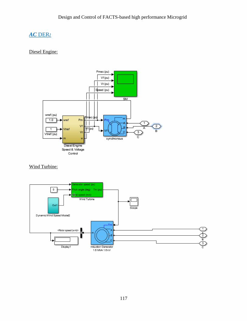
Design and Control of FACTS-based high performance Microgrid
117
AC DER:
Diesel Engine:
Wind Turbine:

Design and Control of FACTS-based high performance Microgrid
118
DC DER:
Batteries
PV Array:
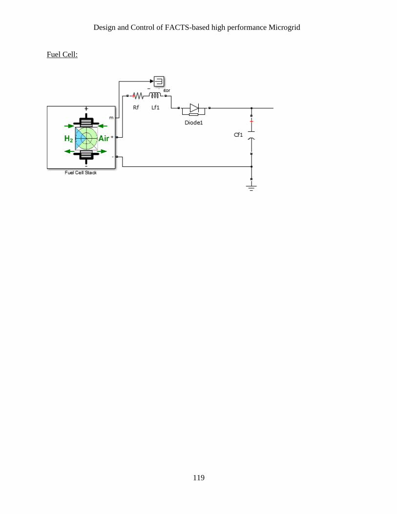
Design and Control of FACTS-based high performance Microgrid
119
Fuel Cell: