design and construction of pile-bents in …reaaa.vms.my/images/4/44/(13-39)design_and... · in...
TRANSCRIPT

International Commemorative Symposium for the Incheon Bridge, Korea, 23 Sep., 2009
DESIGN AND CONSTRUCTION OF PILE-BENTS IN INCHEON BRIDGE PRIVATE INVESTMENT PROJECT
Hyeok-Soo Son Deputy General Manager, Ph.D., Seoyeong Engineering Co., Ltd. [email protected] Suk-Koo Suh Vice President, P.E., Seoyeong Engineering Co., Ltd. [email protected] Sang-Hee Lee Senior Managing Director, P.E., Seoyeong Engineering Co., Ltd. [email protected] Jong-Ho Yang General Manager, Samsung C&T Corporation Co., Ltd. [email protected] Young-Jae Choi General Manager, Samsung C&T Corporation Co., Ltd. [email protected] Abstract: The main objective of this paper is to represent the seismic design of pile-bents in Incheon Bridge Viaduct, which is under construction in Korea. Especially, for the pile-bents, the overall safety against seismic events will be governed by the structural displacement rather than strength capacity. Therefore, it is very important to estimate its seismic performance based on displacement design approach. To estimate the seismic performance of pile-bents, nonlinear push-over analysis on simplified model based on equivalent cantilever column approach was performed. And then, seismic performance assessment was conducted by using ADRS(Acceleration Displacement Response Spectrum) method. From the analysis and assessment results, pile-bents show adequate performance and safety under the given seismic conditions. In addition, the structural analysis method applied to the pile-bents, effective stiffness and reinforcement details in accordance with AASHTO LRFD are summarized. Keywords: pile-bent, seismic design, nonlinear analysis, seismic performance 1. INTRODUCTION Incheon Bridge was primarily planned to link the Incheon International Airport on Yeongjong Island to Songdo City and its construction was launched in June 2005 aiming for completion in 2009. The bridge will be the longest cable-stayed bridge in Korea and the fifth longest one in the world. The private-investment section (12.343 km-long) of the bridge is designed/constructed on a fast-track approach to reduce construction period and make the most of opportunity cost. Sea-crossing section of the Incheon Bridge is composed of 3 major parts such as the Cable-stayed bridge, the Approach bridge and the Viaduct as shown in Figure 1 and Table 1. The typical Viaduct is a 5-span continuous bridge with a 50m span which is a precast prestressed concrete box girder. The superstructure is supported on bearings, composed of the elastomeric bearing and the pot bearing, resting on bridge columns. Elastomeric bearings are installed on expansion joint piers while pot bearings are on intermediate piers to distribute seismic force. Most Viaduct substructures of the bridge use integral pile shaft-columns, so called “pile-
1

International Commemorative Symposium for the Incheon Bridge, Korea, 23 Sep., 2009
bents,” for the first time in Korea. This paper intends to introduce the seismic design and construction of pile-bents of Incheon Bridge’s Viaduct.
Cable-stayed bridge
Approach bridge (east)
Approach bridge (west)
Viaduct (west)
Viaduct (east)
Incheon International Airport
Songdo International City
Cable-stayed bridge
Approach bridge (east)
Approach bridge (west)
Viaduct (west)
Viaduct (east)
Incheon International Airport
Songdo International City
Figure 1 : Incheon bridge private investment project layout
Table 1 : Layout and features of Incheon bridge
Category Layout Features
Cable-Stayed Bridge
• Total length : 1,480m • Spans : 80+260+800+260+80m • Pylon : 230.5m high reinforced concrete • Stay Cables : Two fan-shaped planes of NPWS cables • Deck : 33.4m wide steel box girder
Approach Bridge
• Total length : 889m(west)+889m(east) • Spans : 82+5@145+82=889m • Superstructure : Precast Prestressed Concrete box girder • Pier : Rectangular hollow section • Foundation : Drilled shaft foundation (pile+pile cap)
Viaduct
• Total Length : 5,950m(west)+2,450m(east) • Typical Bridge Length : 5@50m Span Continuous=250m • Substructure : Drilled shaft foundation (pile+pile cap),
Pile-bent (integral pile-shaft column) • Superstructure : Precast Prestressed Concrete box girder
2. PILE-BENTS IN INCHEON BRIDGE VIADUCT Pile-bents use the pile and the column as a continuous single member without a pile-cap, differently from the general substructure foundation composed of 3-kind elements of a pier(column), a pile-cap, and a pile. The advantages of the pile-bents are: 1) Lateral resistance per pile is high due to the large pile diameter; 2) Excavation is reduced since the pile has no pile-cap; 3) Bearing soil layer can be checked during the excavation; 4) Disturbance of surrounding soil is minimized; 5) The pile can penetrate into the stratum where a driven pile is hard to be installed; 6) Noise and vibration can be minimized during construction; and 7) The pile is advantageous to control scour since it can keep a sufficient embedment depth. There are two types of pile-bents as shown in Figure 2. Type I pile-bents are designed so the plastic hinge will form below ground in the pile shaft. Therefore, the cross section of the confined core is the same for both the column and the pile shaft. On the other hand, type II pile-bents are designed so the
2
International Commemorative Symposium for the Incheon Bridge, Korea, 23 Sep., 2009
plastic hinge will form at or above the pile shaft/column interface. Type II shafts usually have diameters larger than those of columns and have sections enlarged by reinforcing cages. (a) Type I (b) Type II
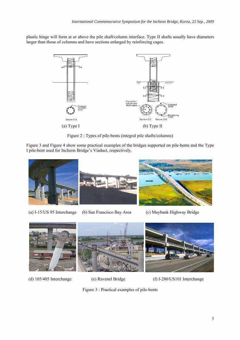
Figure 2 : Types of pile-bents (integral pile shafts/columns) Figure 3 and Figure 4 show some practical examples of the bridges supported on pile-bents and the Type I pile-bent used for Incheon Bridge’s Viaduct, respectively.
(a) I-15/US 95 Interchange (b) San Francisco Bay Area (c) Maybank Highway Bridge
(d) 105/405 Interchange (e) Ravenel Bridge (f) I-280/US101 Interchange
Figure 3 : Practical examples of pile-bents
3

International Commemorative Symposium for the Incheon Bridge, Korea, 23 Sep., 2009
GIRDER
-2% -2%
3,000
2,850DIM MIN.
3,000
2,850DIM MIN.
1,50
01,
500
PIER
300 3,000 300
3,600
1,50
01,
500
2,00
01,
000
GIRDER
2,850DIM MIN.
(a) General View (b) Configuration
Figure 4 : Pile-bents of Viaduct in Incheon Bridge
3. SEISMIC DESIGN Incheon Bridge is a long span marine bridge, which is designed to secure sufficient safety against design seismic events considering the importance and functionality of the bridge. Especially, in the case of Viaduct pile-bents, excessive damage to the pile-bents due to the design seismic force could adversely affect bridge safety and may cause bridge collapse. Seismic design of pile-bents in Incheon Bridge Viaduct has been carried out according to AASHTO LRFD Bridge Design Specifications[1](hereinafter referred to as "AASHTO LRFD"). For the acceleration coefficient and site coefficient, 0.154 and 1.5, were used, respectively. These values correspond to Seismic Zone 2 and Soil Profile Type III in the AASHTO LRFD. The response modification factor, R, for pile-bents specified in AASHTO LRFD is 2.0(Incheon bridge is classified as an “Essential Bridge”), however, the response modification factor of 1.5 was applied according to the PPR(Project Performance Requirements) and CSR(Concessionaire Supplementary Requirements) of Incheon Bridge Project. Therefore, seismic design results of pile-bents in the Incheon Bridge Viaduct will be more conservative than other bridges designed in accordance with AASHTO LRFD. 3.1 Modeling and Analysis Various methods are commonly used for the modeling of seismic response of pile-bents[5,6] as shown in Figure 5. In this study, the 6x6 stiffness matrix model considering nonlinear characteristics of soil layers(p-y spring) was applied to obtain rational analysis results and to provide conveniences to the analysis by using a commercial structural analysis program. Therefore, as shown in Figure 6, the pile and the column are classified on the basis of ground level. MIDAS/CIVIL, which is a structural analysis program, developed by MIDAS IT Co., Ltd. for the column above ground as well as FB-PIER, which is pile nonlinear analysis program developed by Florida DOT, for the pile below ground were applied. The analysis procedures are summarized as follows; - Step 1 : Perform structural analysis on the global bridge model with a fixed end as boundary condition
on ground level. - Step 2 : Determine reaction forces on the ground level based on the analysis results. - Step 3 : Input the reaction forces determined in step 2 as applied loads into the FB-PIER pile analysis
model.
4

International Commemorative Symposium for the Incheon Bridge, Korea, 23 Sep., 2009
- Step 4 : Calculate the representative 6x6 stiffness matrix where nonlinearity of pile and soils are considered.
- Step 5 : Perform re-analysis on the global bridge model with the 6x6 stiffness matrix calculated in step 4 as boundary conditions on ground level.
- Step 6 : Repeat the steps from 2 to 5, until member forces or displacements on the ground level are converged.
(a) pile-bent (b) p-y spring (c) equivalent cantilever (d) 6x6 spring matrix
Figure 5 : Various modeling methods for pile-bent structures
Figure 6 : Modeling and Analysis for Pile-Bent Structure 3.2 Effective Stiffness An assumed stiffness of structural members of a bridge strongly influences the computed response of the seismic conditions. It is widely known that using effective stiffness rather than gross-section stiffness is reasonable in a structural analysis for the seismic design of RC(reinforced concrete) bridge columns.
5

International Commemorative Symposium for the Incheon Bridge, Korea, 23 Sep., 2009
Determining an effective stiffness by moment-curvature nonlinear analysis is the most reasonable and accurate solution. For RC columns, there are some recommended design charts(e.g. ATC-32(2) and Caltrans, Seismic Design Criteria(3)) and proposed equations made based on various experimental and analytical studies and thus the effective stiffness can be calculated relatively simply without conducting complicated nonlinear analysis. However, when it comes to the RC bridge columns surrounded by steel casings(i.e. a type of CFT(Concrete-Filled steel Tubular) composite column) such as the pile-bent in this study, no equation and/or design chart on the effective stiffness has been provided yet. Against this backdrop, in this study, moment-curvature nonlinear analysis was performed in order to calculate the effective stiffness of RC columns with steel casings. The pile/column section considered in this study is a typical design section of pile-bent in the Incheon Bridge Viaduct, with a diameter of 3.0m, a cover of 160mm and the steel casing thickness of 22mm with the specified yield strength of 240MPa as shown in Figure 8(a). Longitudinal reinforcement was provided by 52-D51, giving a longitudinal steel ratio of 0.0149; transverse confinement reinforcement was provided by 2-D19 bundled spirals pitched at 90mm, giving a volumetric ratio of spiral of 0.0092. The concrete compressive strength is 30MPa, the yield strength of both longitudinal and spiral reinforcement is 400MPa, and the applied axial load is 0.12fc′Ag. The moment-curvature analysis results are shown in Figure 8(b). From the analysis result, the effective stiffness of EsIs + 0.5EcIc was applied to the design of pile-bents.
Non-linearBehavior
F
FEL
FEQ
EIgEIeff
y
Elastic Analysis
Δ Δu Δ (a) Definition of effective stiffness (b) Design chart of effective stiffness
Figure 7 : Effective stiffness for RC columns
Conc. comp. strength : 30MPa Re-bar yield strength : 400MPa
9 ) Longitudinal re-bar: 52-D51 (1.4 %Axial force : 25,000kN (0.12fc'Ag)
0
20000
40000
60000
80000
100000
120000
140000
0.00E+00 2.00E-03 4.00E-03 6.00E-03 8.00E-03
Curvature [rad/m]
Mo
ment
[kN
-m
]
WELD SPLICE(TO BE STAGGERED)
W2 D19@3,000
STEEL CASING
22160
3,000
2,68022160
1-2 D51
2-2 D51
2D19@90-1S2
F.B 65X6
RC + Steel casing(t = 22mm)
Yielding (re-bar)
Yielding (steel casing)
RC section
Yielding (re-bar)
(a) Section Detail (b) Moment-Curvature Analysis Results Figure 8 : Moment-curvature analysis results and effective stiffness
6

International Commemorative Symposium for the Incheon Bridge, Korea, 23 Sep., 2009
3.3 Reinforcement Detail Indeed, any bridge design specifications do not make a clear distinction between the pile and the column for pile-bents. Therefore, the pile and the column can be divided on the basis of the ground level from a physical view, or on the basis of moment distribution from a structural engineering view, or on the basis of lateral deflection/lateral support of soil from a geotechnical engineering view. Namely, the reinforcement details of pile-bents may be changed according to the basis of distinction between the pile and the column. Thus, the designer’s reasonable engineering judgment based on structural and geotechnical knowledge and experience are required. Figure 9 shows a representative example of reinforcement details of pile-bents in the Incheon Bridge Viaduct. Under longitudinal seismic response, the bridge acts as a simple vertical cantilever(i.e. plastic hinge will be formed in the vicinity of maximum below-ground moment.), while under transverse seismic response, the pile-bent is subject to double bending(i.e. plastic hinge will be formed both around the column-coping joint and around the maximum below-ground moment.). The longitudinal reinforcements are designed to satisfy the PM(axial force-moment) interaction diagram ignoring the steel casing against plastic seismic moment applying the response modification factor considering steel casing stiffness, and the transverse reinforcements are designed into different types(plastic hinge zone, column-coping joint, non-plastic hinge zone, etc.) in accordance with the AASHTO LRFD.
⇒ 2-D19@75mm
: confinement spiral re-bar (expected plastic hinge region
& connection requirements) ⇒ 2-D19@110mm : minimum spiral re-bar
(column)
⇒ 2-D19@90mm : confinement spiral re-bar (expected plastic hinge region)
⇒ D19@150mm
⇒ D16@225mm
: minimum transverse re-bar (based on shear demand) : minimum transverse re-bar (based on pile requirements)
Figure 9 : Transverse Reinforcement Detail of Pile-Bent
4. ASSESSMENT OF SEISMIC PERFORMANCE The steel casing provides some confinement for the concrete, which in turn delays local buckling of the steel. For seismic performance assessment, in this study, only RC section was considered while effect of steel casing was ignored because that is a mandatory requirement of Incheon Bridge Project based on the PPR. The pile-bent was transformed into equivalent cantilever column as shown in Figure 10(6), and then seismic performance evaluation was conducted. Details of pile-bent that generate maximum member force in the longitudinal direction among the pile-bents of the Viaduct of Incheon Bridge are representatively shown in Figure 8(a) and Figure 9. Figure 11 represents the analysis results on the envelope curve of the lateral load-displacement for the equivalent cantilever column. The aspect ratio(column length/section diameter) of the pile-bent transformed into an equivalent cantilever model is approximately 10. It means that P-Δ effect needs to be considered because the lateral displacement of
7

International Commemorative Symposium for the Incheon Bridge, Korea, 23 Sep., 2009
bridge columns during a seismic event is typically large. Figure 12 represents the result of seismic performance evaluation by using the ADRS(Acceleration Displacement Response Spectrum) method[3], which is very useful and reasonable to evaluate seismic performance because it provides a visual evaluation to present how the structure will perform when it is subject to design earthquake event.
Figure 10 : Equivalent Cantilever Column Figure 11 : Load-Displacement Analysis Result
0.00
0.02
0.04
0.06
0.08
0.10
0.12
0.14
0.16
0.18
0.20
0 20 40 60 80 100 120 140 160 180 200
Spectral Displacement [cm]
Spec
tral A
ccel
erat
ion
[g]
Demand Spectrum(Fu n c tion a l Ope r a tion Le ve l)
(R e tu r n P e r iod=100y r s , A=0.063)
Figure 12 : Seismic Assessment Result for Pile-bent
From the result, the pile-bent satisfies both the functional operation level and collapse prevention level for the design seismic event because the yielding point, A, exceeds the demand spectrum corresponding to the functional operation level and the ultimate point, E, exceeds the demand spectrum corresponding to AASHTO LRFD design seismic event(acceleration coefficient, A=0.154), respectively. With regard to expected damage, it is expected that some flexural crack and longitudinal reinforcement yielding would be developed under the design seismic event based on the general experimental result of RC columns. However, any serious damage which can cause plastic hinge would not be made. Also, after the action of design seismic force, basic function of the bridge will be performed and strength/ductility capacity will be secured without any repair and retrofit. According to the analysis by the ADRS method, pile-bent shows adequate performance and safety under the given seismic conditions. It shows that its seismic performance is adequate for both life safety level and the structural stability level, based on the elastic spectrum with a 5% damping ratio. It is noted that if actual damping ratio of structures and strength of steel casing are considered, the seismic performance will provide safer and more conservative result.
Demand Spectrum(Collapse P revention Level)
(Return Period=1000y rs , A=0.154)
Acce lera tion Coeffic ient : A=0.154 So il Pro file Type : III (S ite Coeffic ient S=1.5)
Capacity Spectrumw ith P-Δ ef fec t
y ie ld ingu l t im ate
crack ing
Δy = 39.2cm Δpe r = 45.2cm
Perfo rm ancePo int
A
B
C
DE
8

International Commemorative Symposium for the Incheon Bridge, Korea, 23 Sep., 2009
5. CONSTRUCTION OF THE PILE-BENT The piles in the pile-bent are constructed by placing fluid concrete in a drilled hole with a steel casing. Reinforcing steels are installed in the excavation prior to placing the concrete.
(a) Working Platform asing Fabrication
(b) Steel C (c) Re-bar Cage Fabrication
(e) Rebar Cage Installation
(d) RCD Excavation (f) Cleaning Bored Hole
9

International Commemorative Symposium for the Incheon Bridge, Korea, 23 Sep., 2009
(g) Pile Concrete Pouring (h) Pile Head Treatment (i) Pier-cap Formwork
(j) Pier-cap Rebar Placing (k) Pier-cap Concrete Placing (l) Completion Figure 13 : Construction of pile-bents in Incheon Bridge Viaduct
The excavation for pile-bents is carried by the Reverse Circulation Drill method & Benoto method as a
e pile. The brief construction sequences are: 1) driving of steel casing; 2) excavation; re-bar cage; 4) placing concrete; and 5) curing. For transverse confinement
inforcement, spiral reinforcing steels with seismic details were used for both the below-ground pile and meter is
the fabrication is carried d
spe s shown in Fig. 13(c). This ances. An
add nstruction. Fig. 9 represents fabrication
typical pile-bents in the Incheon Bridge Viaduct.
his paper covers the outlines of Incheon Bridge (only for the private-investment section), the structural haracteristics of pile-bents, the design and construction cases relavant to Incheon Bridge, the structural
analysis method applied to the pile-bents of Incheon Bridge’s Viaduct, and the reinforcement details in conformity with AASHTO LRFD. Meanwhile, the nonlinear analysis of pile-bents was performed to determine and verify effective stiffness and to evaluate seismic performance. According to the analysis results obtained by ADRS method, the pile-bents show adequate performance and satisfy given seismic conditions. The case studies and design examples introduced in this study are expected to be utilized as reference information for analysis and design of pile-bents to be carried out hereafter. REFERENCES
type of cast-in-plac3) installation of rethe above-ground column. Adopting spiral reinforcing steel for piles or columns with a large dia
first ever trial in Korea. Every rebar cage work including cutting, bending andout by the rebar cage forming machine in the casting yard in accordance with specified drawings an
cifications. The spiral reinforcing steels are fabricated automatically afabrication provides a cage very uniform in length and diameter, with much stricter toler
itional benefit is the cost savings both in fabrication and coand details of reinforcing steel, steel casing, installation of reinforcing steel cage and general view of
6. CONCLUSIONS
Tc
10

International Commemorative Symposium for the Incheon Bridge, Korea, 23 Sep., 2009
11
[1] AASHTO LRFD Bridge Design Specifications, American Association of State Highway and Transportation Officials, 2003 Interim edition, Washington, D.C., USA, 2003.
[2] ATC-32, Improved Seismic Design Criteria for California Bridges : Provisional Recommendations, Report ATC-32, Applied Technology Council, California, USA, 1996.
[3] ATC-40, Seismic Evaluation and Retrofit of Concrete Buildings, Report ATC-40, Applied Technology Council, Redwood City, California, USA, 1996.
[4] Caltrans, Seismic Design Criteria Version 1.3, California Department of Transportation, Sacramento, February, 2004.
[5] Priestley, M. J. N., Seible, F., and Calvi, G. M., Seismic Design and Retrofit of Bridges, John Wiley and Sons, New York, USA, 1996.
[6] T. C. Hutchinson, R. W. Boulanger, Y. H. Chai, and I. M. Idriss, "Inelastic Seismic Response of Extended Pile Shaft Supported Bridge Structures," PEER Report, December 2002.