design and analysis of a compact planar dualband-notched uwb · pdf file ·...
TRANSCRIPT
December, 2015 Microwave Review
Design and Analysis of a Compact Planar DualBand-notched UWB Antenna
Sanjiv Tomar, Ajay Kumar
Abstract – In this paper a compact planar Ultra-wideband
(UWB) antenna with double band-notched characteristics has been presented. The design consists of a unique lamp post shaped radiator fed through a microstrip feedline with one U-shaped slot and a C-shaped slot etched on the radiator and a slotted ground plane. The proposed antenna has been successfully simulated and fabricated. The proposed antenna of size 30 mm x 30 mm printed on 1.6 mm FR4 substrate reports a large bandwidth from 2.6 GHz to 10.7 GHz with VSWR ≤ 2 over the entire range except at two notched bands for WiMax systems at 3.3-3.7 GHz and WLAN systems at 5.15-5.85 GHz. The gain of the antenna increases steadily rom 2 dBi to 5.5 dbi over the entire impedance bandwidth except at notched bands where a sharp dip in gain is noticed. The proposed antenna exhibits nearly omni-directional radiation pattern and a stable gain over the entire impedance bandwidth except for the two notched bands.
Keywords – Ultra-wideband (UWB), dual band-notched antenna, planar UWB antenna, slotted ground plane, C-shaped slot, U-shaped slot, WLAN, WiMax.
I. INTRODUCTION
Since the time Federal Communications Commission (FCC) in Mar 2002 approved [1] the release of S11 ≤ -10 dB un -licencened bandwidth of 7.5 GHz ranging from 3.1 to 10.6 GHz with an effective isotropic radiated power (EIRP) spectral density of -41.3 dBm/MHz for commercial use in radio communication, intense research in the field of UWB communication has been witnessed all over the world to make use of this bandwidth for enhanced data rate and variety of other purposes. The interest of researchers in UWB communication also emanates from the inherent advantage of small size, low power consumption, simple structure and ease of integration together with high transmission rate and relatively good omni-direction property.
While this bandwidth of 7.5 GHz is the core motivation for developing high data rate devices, there exist other narrowband services which may potentially interfere with UWB communication such as WiMax communication at 3.5 GHz (3.3 to 3.7 GHz) and WLAN IEEE 802.11/a operating at 5.2 GHz (5.15 to 5.35 GHz and 5.725 to 5.875 GHz) . Antenna being an essential component of UWB communication, it is thus desired to design the same having band notched function to avoid interference with the existing wireless network technologies. While integrating filters with
Sanjiv Tomar and Ajay Kumar are with Department of Electronics
and Communication Engineering, Manipal University, Jaipur, India, E-mails: [email protected] and [email protected]
the UWB antenna may increase the complexity and cost of manufacturing [2], a simpler way is to use antenna filtering technique which is simple and inexpensive since the antenna size itself is quite small. Till now a number of methods have been reported for band notched functions which includes etching C shaped [3,4], T shaped [5], L shaped [6,7], Pi shaped [8], H and U shaped [9], and E shaped [10] slots and also circular slots on the radiating patch [11], ground plane or feedline. Other methods involve embedding stubs of different shapes or resonating strips near the feedline or near ground plane [12-14] and split ring resonator (SRR) or stepped impedance resonator (SIR) close to feedline [15,16].Use of above mentioned techniques in different combinations can yield single notched band [17-18 ] double notched band [19-20 ] or triple notched band [21-23] capability.
A large number of such antennas have been reported in various research works till now. However, the size of the antennas is relatively large and the notched bands are quite wide in terms of bandwidth and the useable bandwidth is reduced to a large percentage. As a result, intense simulation is needed to make the structure compatible having low profile, stable gain and radiation pattern. This paper is based on simulation and fabrication of a novel design of a dual notched band antenna having a unique lamp post shaped structure using CST Microwave Studio. The double band-notched characteristics have been achieved by making use of one inverted U slot and one C slot etched on the radiating patch. The length of the slot is taken to be one half of the guided wavelength of the centre frequency of the respective notched bands. The length of the each slot can be calculated using the expression (1) as under:
(1)
where fnotch is the centre frequency of the notch band, Lslot is the length of the slot, εeff is the effective dielectric constant and c is the velocity of light in free space.
The position and dimensions of each slot can be altered independently and optimized. The proposed antenna is compact in size having LxW as 30 x 30 mm2 with -10 dB impedance bandwidth of more than 7.5 GHz with two notched bands for avoiding interference from respective narrow band services.
19
Mikrotalasna revija Decembar 2015.
II. DESIGN OF A COMPACT PLANAR MONOPOLE
ANTENNA WITH DOUBLE NOTCHED BANDS SLOTS
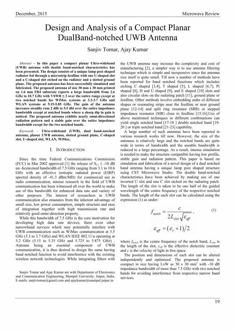
The geometry of the proposed UWB antenna is shown in Fig. 1. The dimension of the proposed antenna is 30 x 30 mm2. It has been prototyped on FR4 substrate of 1.6 mm thickness with dielectric constant εr as 4.4 and loss tangent of 0.02. The antenna is fed through a 50 Ω microstrip feedline having a rectangular ground plane. An inverted U shaped slot and a C shaped slot has been etched on the radiating patch while the ground plane has a square slot to increase the impedance bandwidth. The fabricated antenna is shown in Fig. 2. An initial estimation of the slot dimension was done using the expression (1).
Fig. 1. Geometry of the proposed compact planar UWB antenna
Fig. 2. Photograph of the fabricated compact planar UWB antenna The inverted U-shaped slot S1 is designed to notch the
frequency band covering 3.3 to 3.7 GHz with centre frequency at 3.5 GHz. The second C-shaped slot S2 is designed for frequency band 5.15 to 5.85 GHz with centre frequency of 5.5 GHz. The optimized parameters of the antenna are as follows: L = 30 mm, W= 30 mm, Lg = 12 mm, R = 8.3 mm, W1 = 8 mm, W2 =3 mm, W3 =2 mm, W4 =2 mm, L1 =9.5 mm, L2 = 1 mm, g = 0.4 mm, L3 = 2 mm, W5 = 2.8 mm.
The dimensions of the two slots have been initially estimated based on the expression (1) and later optimized through simulation. The design of the slots is given in Fig. 3 and dimensions of the slots after optimization process are as follows: W6=13.5 mm, W7=0.75 mm, L4= 5 mm, W8= 2.5 mm, W9= 7 mm, W10= 0.65 mm, L5= 4.45 mm.
(a) (b)
Fig. 3. Geometry of (a) Slot S1, (b) Slot S2
III. RESULTS AND DISCUSSION
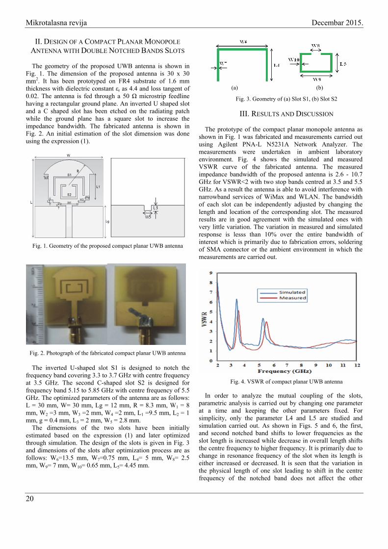
The prototype of the compact planar monopole antenna as shown in Fig. 1 was fabricated and measurements carried out using Agilent PNA-L N5231A Network Analyzer. The measurements were undertaken in ambient laboratory environment. Fig. 4 shows the simulated and measured VSWR curve of the fabricated antenna. The measured impedance bandwidth of the proposed antenna is 2.6 - 10.7 GHz for VSWR<2 with two stop bands centred at 3.5 and 5.5 GHz. As a result the antenna is able to avoid interference with narrowband services of WiMax and WLAN. The bandwidth of each slot can be independently adjusted by changing the length and location of the corresponding slot. The measured results are in good agreement with the simulated ones with very little variation. The variation in measured and simulated response is lesss than 10% over the entire bandwidth of interest which is primarily due to fabrication errors, soldering of SMA connector or the ambient environment in which the measurements are carried out.
Fig. 4. VSWR of compact planar UWB antenna
In order to analyze the mutual coupling of the slots, parametric analysis is carried out by changing one parameter at a time and keeping the other parameters fixed. For simplicity, only the parameter L4 and L5 are studied and simulation carried out. As shown in Figs. 5 and 6, the first, and second notched band shifts to lower frequencies as the slot length is increased while decrease in overall length shifts the centre frequency to higher frequency. It is primarily due to change in resonance frequency of the slot when its length is either increased or decreased. It is seen that the variation in the physical length of one slot leading to shift in the centre frequency of the notched band does not affect the other
20
December, 2015 Microwave Review
notched bands. It is due to the fact that the etched slots are located at different location and coupling between them is quite weak. It can therefore be inferred that the notched band can be controlled individually by controlling the dimension and location of the slots. Dimension of gap ‘g’ is also changed to study its effect on VSWR. As seen in Fig. 7 that on increasing the dimension of gap ‘g’ between lower edge of radiator patch and upper edge of ground plane, the notched bands cantered at 3.5 GHz and 5.5 GHz shifts to lower frequency while decrease in gap dimension shifts the centre frequency to higher ones.
Fig. 5. Optimization of slot L4
Fig. 6. Optimization of slot L5
Fig. 7. Optimization of gap ‘g’
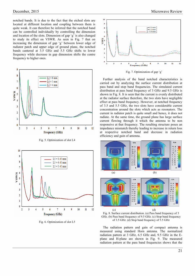
Further analysis of the band notched characteristics is carried out by analyzing the surface current distribution at pass band and stop band frequencies. The simulated current distribution at pass band frequency of 3 GHz and 9.5 GHz is shown in Fig. 8. It is seen that the current is evenly distributed at the radiator surface therefore, the two slots have negligible effect at pass band frequency. However, at notched frequency of 3.5 and 5.5 GHz, the two slots have considerable current concentration around the slots which acts as resonators. The current in radiator patch is quite small and hence, it does not radiate. At the same time, the ground plane has large surface current flowing through it which the antenna to be non responsive at that frequency. The resulting structure poses an impedance mismatch thereby leading to increase in return loss at respective notched band and decrease in radiation efficiency and gain of antenna.
(a) (b) (c) (d)
Fig. 8. Surface current distribution. (a) Pass band frequency of 3 GHz. (b) Pass band frequency of 9.5 GHz. (c) Stop band frequency
of 3.5 GHz. (d) Stop band frequency of 5.5 GHz
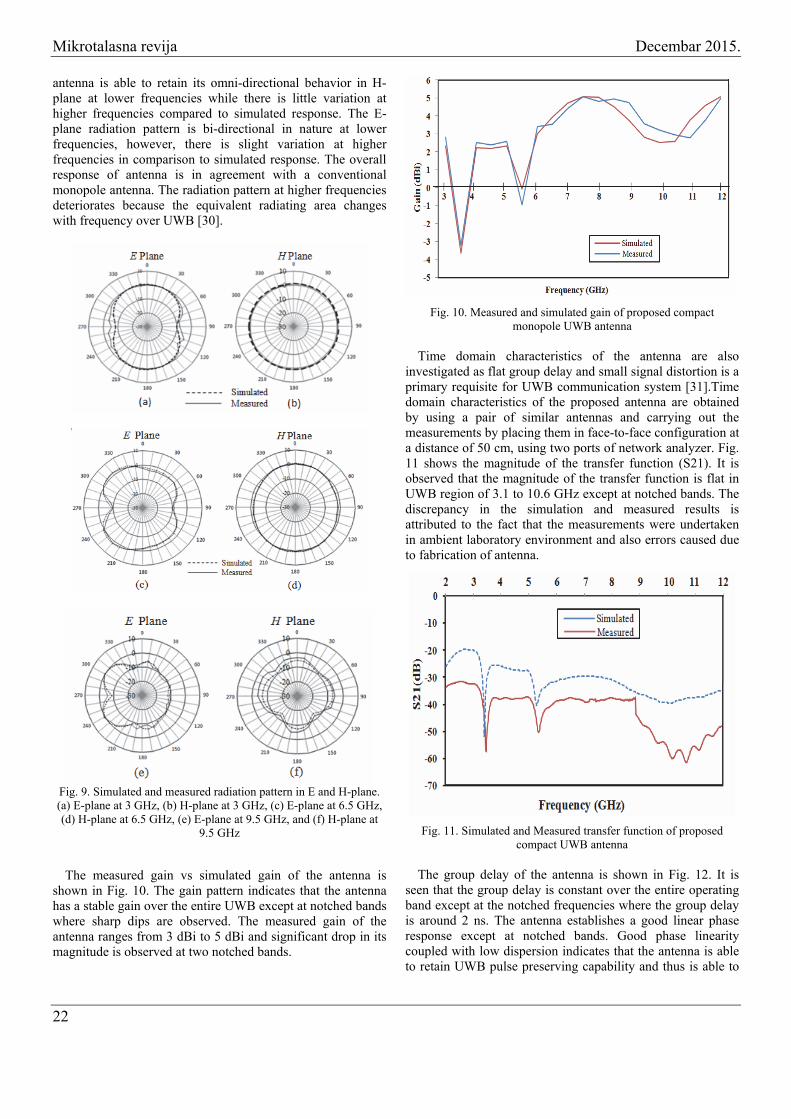
The radiation pattern and gain of compact antenna is measured using standard Horn antenna. The normalized radiation pattern at 3 GHz, 6.5 GHz and, 9.5 GHz in the E-plane and H-plane are shown in Fig. 9. The measured radiation pattern at the pass band frequencies shows that the
21
Mikrotalasna revija Decembar 2015.
antenna is able to retain its omni-directional behavior in H-plane at lower frequencies while there is little variation at higher frequencies compared to simulated response. The E-plane radiation pattern is bi-directional in nature at lower frequencies, however, there is slight variation at higher frequencies in comparison to simulated response. The overall response of antenna is in agreement with a conventional monopole antenna. The radiation pattern at higher frequencies deteriorates because the equivalent radiating area changes with frequency over UWB [30].
Fig. 9. Simulated and measured radiation pattern in E and H-plane. (a) E-plane at 3 GHz, (b) H-plane at 3 GHz, (c) E-plane at 6.5 GHz, (d) H-plane at 6.5 GHz, (e) E-plane at 9.5 GHz, and (f) H-plane at
9.5 GHz
The measured gain vs simulated gain of the antenna is
shown in Fig. 10. The gain pattern indicates that the antenna has a stable gain over the entire UWB except at notched bands where sharp dips are observed. The measured gain of the antenna ranges from 3 dBi to 5 dBi and significant drop in its magnitude is observed at two notched bands.
Fig. 10. Measured and simulated gain of proposed compact monopole UWB antenna
Time domain characteristics of the antenna are also
investigated as flat group delay and small signal distortion is a primary requisite for UWB communication system [31].Time domain characteristics of the proposed antenna are obtained by using a pair of similar antennas and carrying out the measurements by placing them in face-to-face configuration at a distance of 50 cm, using two ports of network analyzer. Fig. 11 shows the magnitude of the transfer function (S21). It is observed that the magnitude of the transfer function is flat in UWB region of 3.1 to 10.6 GHz except at notched bands. The discrepancy in the simulation and measured results is attributed to the fact that the measurements were undertaken in ambient laboratory environment and also errors caused due to fabrication of antenna.
Fig. 11. Simulated and Measured transfer function of proposed
compact UWB antenna
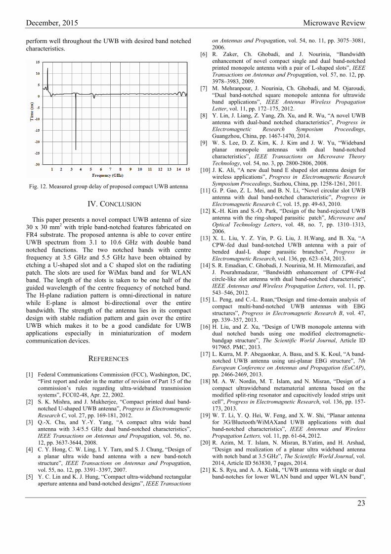
The group delay of the antenna is shown in Fig. 12. It is seen that the group delay is constant over the entire operating band except at the notched frequencies where the group delay is around 2 ns. The antenna establishes a good linear phase response except at notched bands. Good phase linearity coupled with low dispersion indicates that the antenna is able to retain UWB pulse preserving capability and thus is able to
22
December, 2015 Microwave Review
perform well throughout the UWB with desired band notched characteristics.
Fig. 12. Measured group delay of proposed compact UWB antenna
IV. CONCLUSION
This paper presents a novel compact UWB antenna of size 30 x 30 mm2 with triple band-notched features fabricated on FR4 substrate. The proposed antenna is able to cover entire UWB spectrum from 3.1 to 10.6 GHz with double band notched functions. The two notched bands with centre frequency at 3.5 GHz and 5.5 GHz have been obtained by etching a U-shaped slot and a C shaped slot on the radiating patch. The slots are used for WiMax band and for WLAN band. The length of the slots is taken to be one half of the guided wavelength of the centre frequency of notched band. The H-plane radiation pattern is omni-directional in nature while E-plane is almost bi-directional over the entire bandwidth. The strength of the antenna lies in its compact design with stable radiation pattern and gain over the entire UWB which makes it to be a good candidate for UWB applications especially in miniaturization of modern communication devices.
REFERENCES
[1] Federal Communications Commission (FCC), Washington, DC, “First report and order in the matter of revision of Part 15 of the commission’s rules regarding ultra-wideband transmission systems”, FCC02-48, Apr. 22, 2002.
[2] S. K. Mishra, and J. Mukherjee, “Compact printed dual band-notched U-shaped UWB antenna”, Progress in Electromagnetic Research C, vol. 27, pp. 169-181, 2012.
[3] Q.-X. Chu, and Y.-Y. Yang, “A compact ultra wide band antenna with 3.4/5.5 GHz dual band-notched characteristics”, IEEE Transactions on Antennas and Propagation, vol. 56, no. 12, pp. 3637-3644, 2008.
[4] C. Y. Hong, C. W. Ling, I. Y. Tarn, and S. J. Chung, “Design of a planar ultra wide band antenna with a new band-notch structure”, IEEE Transactions on Antennas and Propagation, vol. 55, no. 12, pp. 3391–3397, 2007.
[5] Y. C. Lin and K. J. Hung, “Compact ultra-wideband rectangular aperture antenna and band-notched designs”, IEEE Transactions
on Antennas and Propagation, vol. 54, no. 11, pp. 3075–3081, 2006.
[6] R. Zaker, Ch. Ghobadi, and J. Nourinia, “Bandwidth enhancement of novel compact single and dual band-notched printed monopole antenna with a pair of L-shaped slots”, IEEE Transactions on Antennas and Propagation, vol. 57, no. 12, pp. 3978–3983, 2009.
[7] M. Mehranpour, J. Nourinia, Ch. Ghobadi, and M. Ojaroudi, “Dual band-notched square monopole antenna for ultrawide band applications”, IEEE Antennas Wireless Propagation Letter, vol. 11, pp. 172–175, 2012.
[8] Y. Lin, J. Liang, Z. Yang, Zh. Xu, and R. Wu, “A novel UWB antenna with dual-band notched characteristics”, Progress in Electromagnetic Research Symposium Proceedings, Guangzhou, China, pp. 1467-1470, 2014.
[9] W. S. Lee, D. Z. Kim, K. J. Kim and J. W. Yu, “Wideband planar monopole antennas with dual band-notched characteristics”, IEEE Transactions on Microwave Theory Technology, vol. 54, no. 3, pp. 2800-2806, 2008.
[10] J. K. Ali, “A new dual band E shaped slot antenna design for wireless applications”, Progress in Electromagnetic Research Symposium Proceedings, Suzhou, China, pp. 1258-1261, 2011.
[11] G. P. Gao, Z. L. Mei, and B. N. Li, “Novel circular slot UWB antenna with dual band-notched characteristic”, Progress in Electromagnetic Research C, vol. 15, pp. 49-63, 2010.
[12] K.-H. Kim and S.-O. Park, “Design of the band-rejected UWB antenna with the ring-shaped parasitic patch”, Microwave and Optical Technology Letters, vol. 48, no. 7, pp. 1310–1313, 2006.
[13] X. L. Liu, Y. Z. Yin, P. G. Liu, J. H.Wang, and B. Xu, “A CPW-fed dual band-notched UWB antenna with a pair of bended dual-L shape parasitic branches”, Progress in Electromagnetic Research, vol. 136, pp. 623–634, 2013.
[14] S. R. Emadian, C. Ghobadi, J. Nourinia, M. H. Mirmozafari, and J. Pourahmadazar, “Bandwidth enhancement of CPW-Fed circle-like slot antenna with dual band-notched characteristic”, IEEE Antennas and Wireless Propagation Letters, vol. 11, pp. 543–546, 2012.
[15] L. Peng, and C.-L. Ruan,“Design and time-domain analysis of compact multi-band-notched UWB antennas with EBG structures”, Progress in Electromagnetic Research B, vol. 47, pp. 339–357, 2013.
[16] H. Liu, and Z. Xu, “Design of UWB monopole antenna with dual notched bands using one modified electromagnetic-bandgap structure”, The Scientific World Journal, Article ID 917965. PMC, 2013.
[17] L. Kurra, M. P. Abegaonkar, A. Basu, and S. K. Koul, “A band-notched UWB antenna using uni-planar EBG structure”, 7th European Conference on Antennas and Propagation (EuCAP), pp. 2466-2469, 2013.
[18] M. A. W. Nordin, M. T. Islam, and N. Misran, “Design of a compact ultrawideband metamaterial antenna based on the modified split-ring resonator and capacitively loaded strips unit cell”, Progress in Electromagnetic Research, vol. 136, pp. 157-173, 2013.
[19] W. T. Li, Y. Q. Hei, W. Feng, and X. W. Shi, “Planar antenna for 3G/Bluetooth/WiMAXand UWB applications with dual band-notched characteristics”, IEEE Antennas and Wireless Propagation Letters, vol. 11, pp. 61-64, 2012.
[20] R. Azim, M. T. Islam, N. Misran, B.Yatim, and H. Arshad, “Design and rrealization of a planar ultra wideband antenna with notch band at 3.5 GHz”, The Scientific World Journal, vol. 2014, Article ID 563830, 7 pages, 2014.
[21] K. S. Ryu, and A. A. Kishk, “UWB antenna with single or dual band-notches for lower WLAN band and upper WLAN band”,
23
Mikrotalasna revija Decembar 2015.
24
IEEE Transactions on Antennas and Propagation, vol. 57, pp. 3942-3950, 2009.
[22] H. S. Schantz, G. Wolenec, and E. M. Myszka,“Frequency notched UWB antennas”, IEEE Proceedings, UWBST, pp. 214-218, 2003.
[23] H.-J. Zhou, B-H. Sun, Q-Zh Liu, and J-Y. Deng, “Implementation and investigation of U-shaped aperture UWB antenna with dual band-notched characteristics”, Electronics Letters, vol. 44, no. 24, pp. 1387-1388, 2008.
[24] Q-X. Chu, and Y-Y. Yang, “3.5/5.5 GHz dual band-notch ultra-wideband antenna”, Electronics Letters, vol 44, no. 3, pp. 172-174, 2008.
[25] T. D. Nguyen, D. H. Lee, and H. Ch. Park, “Design and analysis of compact printed triple band-notched UWB antenna”, IEEE Antennas and Wireless Propagation Letters, vol. 10, pp. 403-406, 2011.
[26] J.-Y. Deng, Y-Z. Yin, Sh-G. Zhou, and Q-Zh. Liu, “Compact ultra-wideband antenna with tri-band notched characteristic”, Electronics Letters , vol 44, no. 21, pp. 1231-1233, 2008.
[27] M. M. Sharma, J. K. Deegwal, A. Kumar, and M. C. Govil, “Compact planar monopole antenna with quadruple band-notched characteristics”, Progress in Electromagnetic Research C, vol. 47, pp. 29-36, 2014.
[28] Ch.-M. Luo, J.-S. Hong, and H. Xiong, “A tri-notched UWB antenna with low mutual coupling between the band-notched structure”, Radioengineering, vol. 22, no 4, pp. 1233-1238, 2013.
[29] Q.-X. Chu, and Y.-Y. Yang, “A compact ultrawideband antenna with 3.4/5.5 GHz dual band-notched characteristics”, IEEE Transactions on Antenna and Propagation, vol. 56, no. 12, pp. 3637-3644, 2008.
[30] Q. Wu, R. Jin, J. Gong, and M. Ding, “Printed omni-directional UWB antenna with very compact size”, IEEE Transactions on Antennas and Propagation, vol. 56, pp. 896-899, 2008.
[31] Q. Wang, and Y. Zhang, “Design of a compact UWB antenna with triple band notched characteristics”, International Journal of Antennas and Propagation, vol. 2014, Article ID 892765, 2014.