design & simulation of optical fiber bragg grating pressure sensor
TRANSCRIPT

Journal of Theoretical and Applied Information Technology
© 2005 - 2009 JATIT. All rights reserved.
www.jatit.org
515
DESIGN & SIMULATION OF OPTICAL FIBER BRAGG GRATING PRESSURE SENSOR FOR MINIMUM
ATTENUATION CRITERIA
1REEMA SHARMA, 2RAJESH ROHILLA, 3 MOHIT SHARMA, 4DR. T.C.MANJUNATH, Ph.D. (IIT Bombay), Fellow IETE, Member IEEE
1Lecturer, E & C Engg. Dept., New Horizon College of Engg., Bangalore, Karnataka, India. Email : [email protected] Phone : +91 09901048873; Fax : 080-28440770
2Former Lecturer, E & C Engg. Dept., National Institute of Technology, Kurukshetra, Haryana, India. 3Team Leader, Hewlett Packard, Bangalore, Karnataka, India
Email : [email protected] Phone : +91 09845558034 4Professor & Head, E & C Engg. Dept., New Horizon College of Engg., Bangalore, Karnataka, India.
Email : [email protected] [email protected] Phone : +91 080 66297777 (Off.) +91 09449820361 (Mob) Extn. 2004 ; Fax : 080-28440770
ABSTRACT
This paper presents the design & simulation of an Optical Fiber Bragg Grating (OFBG) sensor for stress, strain measurement and also demonstrates the methodology to arrive at the optimal grating pitch dimensions for a given interrogating wavelength. The wavelength chosen for interrogation of the Fiber Bragg Grating (FBG) sensor is from the third window so as to minimize the attenuation of the light signal in the communication link from Fiber Bragg Grating sensor to the electronic instrumentation. Before actually inscribing the grating in the fiber, simulation tools provide valuable help in optimizing the design parameters. From the graphical simulations, it can be concluded that increase in the grating pitch will change the reflectivity of the interrogating wavelength. Once the sensor is simulated using the advanced simulation tools, then it is tested for its reliability. The simulation results presented in this paper show the effectiveness of the developed method, which can be further implemented in real time for various industrial applications. Keywords : Fiber, Bragg Grating, Sensor, Optics, Simulation, Instrumentation, Window, Modulation,
Power, Reflection, Wave-length. 1. INTRODUCTION
Over the past 20 years, two major product revolutions have taken place due to the growth of the photonics, opto-electronics and the fiber optic communication industries. The opto-electronics industry has brought about such products as compact disc players, laser printers, bar code scanners and laser pointers. The fiber optic communication industry has literally revolutionized the telecommunication industry by providing higher performance, more reliable telecommunication links with ever decreasing bandwidth cost. This revolution is bringing about the benefits of high volume production to component users and a true information super-highway built of glass [1]. In parallel with these developments, fiber optic sensor technology has been a major user of technology
associated with the opto-electronic & fiber optic communication industry.
Many of the components associated with these industries were often developed for fiber optic sensor applications. Fiber optic sensor technology in turn has often been driven by the development and subsequent mass production of components to support these industries [2]. As component prices have fallen and quality improvements have been made, the ability of fiber optic sensors to displace the traditional sensors for rotation, acceleration, electric and magnetic field measurement, temperature, pressure, displacement, acoustics, vibration and linear and angular position, stress, strain, humidity viscosity, chemical measurements and a host of other sensor applications, has been enhanced. In the early days of fiber optic sensor

Journal of Theoretical and Applied Information Technology
© 2005 - 2009 JATIT. All rights reserved.
www.jatit.org
516
technology, most commercially successful fiber optic sensors were squarely targeted at the markets where existing sensor technology was marginal or in many cases non-existent [3].
An optical fiber (or fibre) is a glass or plastic fiber that carries light along its length. Fiber optics is the overlap of applied science and engineering concerned with the design and application of optical fibers. Optical fibers are widely used in fiber-optic communications, which permits transmission over longer distances and at higher bandwidths (data rates) than other forms of communications. Fibers are used instead of metal wires because signals travel along them with less loss, and they are also immune to electromagnetic interference [38].
Light is kept in the core of the optical fiber by total internal reflection. This causes the fiber to act as a waveguide. Fibers which support many propagation paths or transverse modes are called multi-mode fibers (MMF), while those which can only support a single mode are called single-mode fibers (SMF). Multi-mode fibers generally have a larger core diameter, and are used for short-distance communication links and for applications where high power must be transmitted. Single-mode fibers are used for most communication links longer than 550 meters (600 yards).
Fibers are also used for illumination, and are wrapped in bundles so they can be used to carry images, thus allowing viewing in tight spaces. Specially designed fibers are used for a variety of other applications, including sensors and fiber lasers [38]. Fibers have many uses in remote sensing. In some applications, the sensor is itself an optical fiber. In other cases, fiber is used to connect a non-fiberoptic sensor to a measurement system.
Depending on the application, fiber may be used because of its small size, or the fact that no electrical power is needed at the remote location, or because many sensors can be multiplexed along the length of a fiber by using different wavelengths of light for each sensor, or by sensing the time delay as light passes along the fiber through each sensor. Time delay can be determined using a device such as an optical time-domain reflectometer [38].
Optical fibers can be used as sensors to measure strain, temperature, pressure and other quantities by modifying a fiber so that the quantity to be measured modulates the intensity, phase, polarization, wavelength or transit time of light in the fiber. Sensors that vary the intensity of light are the simplest, since only a simple source and
detector are required. A particularly useful feature of such fiber optic
sensors is that they can, if required, provide distributed sensing over distances of up to one meter. Extrinsic fiber optic sensors use an optical fiber cable, normally a multi-mode one, to transmit modulated light from either a non-fiber optical sensor, or an electronic sensor connected to an optical transmitter. A major benefit of extrinsic sensors is their ability to reach places which are otherwise inaccessible [39].
An example is the measurement of temperature inside aircraft jet engines by using a fiber to transmit radiation into a radiation pyrometer located outside the engine. Extrinsic sensors can also be used in the same way to measure the internal temperature of electrical transformers, where the extreme electromagnetic fields present make other measurement techniques impossible. Extrinsic sensors are used to measure vibration, rotation, displacement, velocity, acceleration, torque, and twisting.
The inherent advantages of fiber optic sensors which include their ability to be light-weight of very small size, passive, low power, resistant to electromagnetic interference, high sensitivity, wide bandwidth and environmental ruggedness were heavily used to offset their major disadvantages of high cost and unfamiliarity to the end-user [40].
Generally, optical fibers are used for communication. However, these days optical fibers are being increasingly used in sensing applications in the area of civil structures, novel materials, medicines, aerospace, power generation, transportation, military and scientific research [1-9]. Their insensitivity to electromagnetic radiations offers wide usage in places where other instruments are unable to function properly due to effects of radiations. Besides being EMI / RFI immune, optical fibers are electrically inert and its flexibility and small size makes routing easy [5].
Nuclear environments are one such place where optical fiber sensors are being used. However, when optical fibers are exposed to ionizing radiations it results in a wavelength-dependent attenuation increase [10-13]. The use of fiber bragg grating sensors can circumvent this problem.
Fiber Bragg Gratings (FBGs) are spectral filters fabricated within the segments of optical fibers. They typically reflect light over a narrow wavelength range and transmit all other wavelengths, but they also can be designed to have more complex spectral responses [4].

Journal of Theoretical and Applied Information Technology
© 2005 - 2009 JATIT. All rights reserved.
www.jatit.org
517
Many users exist for FBGs in today’s fiber communication systems, which rely heavily on Dense Wavelength Division Multiplexing (DWDM) and optical amplification. Besides this, FBGs have found applications in sensor systems, which they stand out from all other technologies, in the performance, reliability & the cost. A FBG consists of a periodic modulation of the index of refraction along the core of an optical fiber.
FBGs are created by exposition of a photosensitive fiber to an intensity pattern of UV light. In its basic form, the resulting grating reflects selectively the light guided by the optical fiber at the bragg wavelength λ = 2nΛ , where n and Λ are the effective index of refraction of the fiber and the pitch of the grating in the fiber respectively [14].
Various types of simulation software packages are available on the Internet like PC-Grate, GratingMod, SPSS, FOGS, etc for the simulation of a FBG sensor. Complete documentation in the form of user guides and manuals are available as .pdf files and support is also available in the form of example model files. FBG model can be constructed using one of these software packages and simulated to evaluate grating efficiency for various grating shape parameters, number of plane sections and wavelengths [7].
In this research paper, an optical FBG sensor model is being simulated with the help of advanced software modules such as the GratingMODTM and the modeled sensor is evaluated for the grating efficiency for various grating shape parameters, pitch, the number of plane sections and different wavelengths. Finally, the results are summarized. Before actually inscribing the grating in the fiber, simulation tools provide a valuable help in optimizing the design parameters [6] which is being taken care of in our research work.
The paper [40] is organized in the following sequence. A brief introduction to the related work and the literature survey, i.e., about the optic fiber sensors and about the FBGs was presented in the previous paragraphs, i.e., in section 1. The section 2 depicts the information about the software methodology used to design the FBG sensor. In the section 3, the design details of the FBG sensor is presented with the step-by-step procedure. Next, the simulation results along with the discussions about the work touched upon in this paper is presented. Further, this section is followed by the conclusions & the scope for future work in this area, acronyms, the references & the biographies.
2 SOFTWARE METHODOLOGY USED TO DESIGN THE FBG SENSOR
In this section, we describe the methodology that has been used in the software tool for designing the Fiber Bragg Grating sensor. The tool used is GratingMODTM and is a general design tool for analysing and synthesizing complicated grating profiles in optical fibres and integrated wave-guide circuits for a wide variety of photonic applications. Speedy algorithms, capable of handling gratings embedded in arbitrary wave-guide profiles, make the GratingMOD a synergistic addition to the Rsoft tool-suite. The following steps give a brief introduction about the various concepts that are used in the design and simulation of the FBG sensor that is done in our research work using the Grating MOD tool.
Setting up of the fiber The grating layout utility Modifying the utility output Displaying the index profile Performing the first simulation Performing the second simulation Decorating the plots (optional) Reflection spectra & delay vs. wavelength
3. DESIGN OF THE FBG SENSOR
FBG’s are flexible and affordable components in many of the fiber optic systems. A whole host of fiber parameters can be modified in order to obtain a desired spectral performance, including, index modulation, structure length, apodization, chirp and the ability to control the type and the number of both forward and backward propagating modes. In this work, we are using the GratingMOD to simply change the refractive index modulation depth of a FBG and note the changes in the reflection spectra. The user is encouraged further to explore the effects of apodization, chirp and grating length on their own [8].
Fiber Bragg Gratings are based on the principle of Bragg reflection. When light propagates through periodically alternating regions of higher and lower refractive index, it is partially reflected at each interface between those regions. If the spacing between those regions is such that all the partial reflections add up in phase when the round trip of the light between two reflections is an integral number of wavelengths, the total reflection can grow nearly 100 %, even if the individual reflections are very small.

Journal of Theoretical and Applied Information Technology
© 2005 - 2009 JATIT. All rights reserved.
www.jatit.org
518
Of course, that condition will hold only for specific wavelengths. For all other wavelengths, the out of phase reflections end up cancelling each other, resulting in high transmission. The condition for high reflection is known as Bragg condition. FBG consists of a periodic modulation of the index of refraction along the core of an optical fiber as shown in Fig. 1.
Fig. 1 : Principle of operation of a FBG sensor
FBG sensors are based on the fact that the Bragg wavelength changes with change in the pitch of the grating and the change in the refractive index [15]. Thus, any physical parameter (like temperature, stress, strain) which causes change in the above mentioned parameters can be sensed using a FBG, by measuring the shift in the Bragg wavelength or the change in reflection coefficient of a particular wavelength [27].
The manufacturing techniques for Fiber Bragg Gratings are still evolving. The earliest and still one of the most popular, side writing methods for producing fiber gratings is the UV holographic [16-18]. This uses two-beam interference from amplitude splitting mirror interferometer to fabricate the gratings [28]. The UV holographic method has the advantage of being a flexible system which allows gratings to be written over a wide range of wavelengths, but does require a mechanically stable experimental set-up for CW or multipulse writing. Adjusting the angle of intersection between the two writing beams controls the Bragg wavelength. Another common method of grating fabrication is to use a phase mask [29].
In the usual near field configuration, the diffracted first order beams from the phase mask interfere at the optical fiber placed in close proximity to the phase mask surface. In the far field version the +/− 1 order beams are reflected off the sides of a fused silica block before they are recombined at the optical fiber [30].
The phase mask techniques are less sensitive to environmental disturbances and produce gratings with highly repeatable characteristics. Manufacturing facility for fiber Bragg gratings involves huge infrastructure and financial involvement. Simulation is an important tool which
helps us in optimal design of fiber Bragg grating sensors before fabricating [31]. Different operations are involved in the design of the FBG sensor, which could be briefly discussed as follows one after another. 3.1 SETTING UP OF THE FIBER
Consider a simple uniform FBG and define the FBG via a sinusoidal index perturbation along the propagation axis of the fiber. The fiber cladding index normally chosen is to be around 1.45, and in this paper, it is assumed to be infinite. The fiber core will be 5.25 μm in diameter, and will have an index of 1.458. The modulation depth of the index perturbation will be varied in order to visualize the changes in the grating performance around a particular central wave-length. Note that the 3D structure type is a fiber, simulation tool used is Grating MOD & the profile type is a step index / single mode.
3.2 THE GRATING LAYOUT UTILITY
The grating layout utility is used to speed up the time needed to produce this type of grating for the particular specification chosen by us. Open the grating layout utility via the utility option in the CAD menu. Set the layout option to fiber, the grating type to volume index, and the modulation depth to 0.0012 in order to specify that we wish to create an index modulated fiber structure.
Then, set the width and height to 5.25 μm, and delta to 0.008 to set the index and geometry related parameters. Finally, enter a layout file meta pre-fix such as fbg and click the OK button. The file, fbg.ind, will be created and will be opened automatically in the CAD window [9] as shown in the Fig. 2.
The created file fbg.ind contains a single fiber segment with the desired index perturbation. The user is encouraged to explore the segment properties dialog box, which can be accessed by right-clicking on the segment. This dialog box controls all the parameters for the fiber, including the index modulation and perturbation. In this case, the index perturbation is set by a user-defined grating taper function [10].
3.3 MODIFYING THE UTILITY OUTPUT
Once the basic structure is defined, we need to make several additional modifications in order to obtain the desired structure. Open the global setting dialog box, and change the value of the
Journal of Theoretical and Applied Information Technology
© 2005 - 2009 JATIT. All rights reserved.
www.jatit.org
519
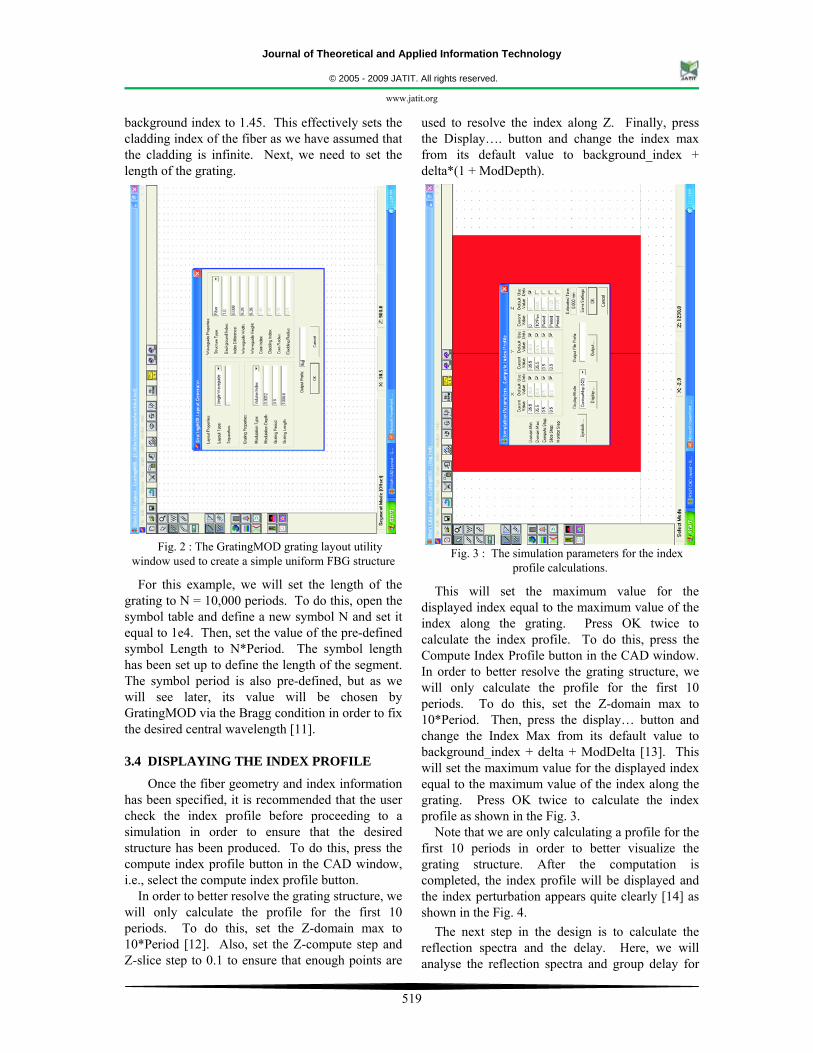
background index to 1.45. This effectively sets the cladding index of the fiber as we have assumed that the cladding is infinite. Next, we need to set the length of the grating.
Fig. 2 : The GratingMOD grating layout utility window used to create a simple uniform FBG structure
For this example, we will set the length of the grating to N = 10,000 periods. To do this, open the symbol table and define a new symbol N and set it equal to 1e4. Then, set the value of the pre-defined symbol Length to N*Period. The symbol length has been set up to define the length of the segment. The symbol period is also pre-defined, but as we will see later, its value will be chosen by GratingMOD via the Bragg condition in order to fix the desired central wavelength [11]. 3.4 DISPLAYING THE INDEX PROFILE
Once the fiber geometry and index information has been specified, it is recommended that the user check the index profile before proceeding to a simulation in order to ensure that the desired structure has been produced. To do this, press the compute index profile button in the CAD window, i.e., select the compute index profile button.
In order to better resolve the grating structure, we will only calculate the profile for the first 10 periods. To do this, set the Z-domain max to 10*Period [12]. Also, set the Z-compute step and Z-slice step to 0.1 to ensure that enough points are
used to resolve the index along Z. Finally, press the Display…. button and change the index max from its default value to background_index + delta*(1 + ModDepth).
Fig. 3 : The simulation parameters for the index profile calculations.
This will set the maximum value for the displayed index equal to the maximum value of the index along the grating. Press OK twice to calculate the index profile. To do this, press the Compute Index Profile button in the CAD window. In order to better resolve the grating structure, we will only calculate the profile for the first 10 periods. To do this, set the Z-domain max to 10*Period. Then, press the display… button and change the Index Max from its default value to background_index + delta + ModDelta [13]. This will set the maximum value for the displayed index equal to the maximum value of the index along the grating. Press OK twice to calculate the index profile as shown in the Fig. 3.
Note that we are only calculating a profile for the first 10 periods in order to better visualize the grating structure. After the computation is completed, the index profile will be displayed and the index perturbation appears quite clearly [14] as shown in the Fig. 4.
The next step in the design is to calculate the reflection spectra and the delay. Here, we will analyse the reflection spectra and group delay for

Journal of Theoretical and Applied Information Technology
© 2005 - 2009 JATIT. All rights reserved.
www.jatit.org
520
various index modulation depths. We will produce the results for a modulation depth of both 0.0012 and 0.0003 and then display these results later.
Fig. 4 : The computed index profile for a uniform FBG
3.5 PERFORMING THE FIRST SIMULATION
Before starting the simulation process, note that we have set the grating to have a 0.0012 modulation depth. This is done via the symbol ModDelta, which was defined by the grating layout utility.
To perform the simulation, click the Perform Simulation Icon in the CAD window to open the GratingMod analysis dialog box. Be sure that the simulation module is set to Grating analysis, which indicates that a grating analysis will be performed [15].
As discussed earlier, we are going to fix the central wavelength and allow the GratingMod to calculate the Period in order to satisfy the Bragg condition.
To enable this, select Fix Centre Wavelength and then set the wavelength to 1.55. For this example, the default values for the rest of the simulation parameters are appropriate [16] as shown in Fig. 5.
Next, click the output…. button in order to set the output options for this simulation. Set output spectrum to reflected and show the delay / dispersion to yes. This will save the desired data
from the simulation to disk. Finally, set an output prefix such as bragg_12 and click OK to perform the simulation [17].
Fig. 5 : The GratingMod simulation parameters for the
grating analysis
Fig. 6 (a) : The simulation results from the first grating analysis
The reflection spectrum contained in the file shown, bragg_12.dat. Note that the grating period automatically calculated to satisfy the Bragg condition is displayed on
the top of the graph.
After the automatic mode calculation, the reflected spectrum will be shown. The data from this simulation has been saved in the files with the

Journal of Theoretical and Applied Information Technology
© 2005 - 2009 JATIT. All rights reserved.
www.jatit.org
521
prefix bragg_12 with the associated plot files. For instance, the reflection spectrum data is saved in the file bragg_12.dat with an associated WinPLOT file bragg_12.pics. The first simulation results are shown in the Figs. 6(a) & (b) respectively. The user is encouraged to look through the contents of the current working directory in order to see the files produced [18].
Fig. 6 (b) : Simulation results from 1st grating analysis The delay information is contained in the file
bragg_12_delay_dispersion.pcs
3.6 PERFORMING SECOND SIMULATION
Once the first simulation is complete, a second simulation can be performed with a modulation depth of 0.0003. Change the value of ModDelta to 0.0003, set the output prefix to a different name, such as bragg_03 and perform a second simulation. The results will be saved in files with the prefix bragg_03.dat [19]. The second simulation results are shown in the Figs. 7(a) & (b) respectively.
Fig. 7 (a) : The simulation results from the first grating analysis
The reflection spectrum contained in the file shown, bragg_03.dat. Note that the grating period automatically calculated to satisfy the Bragg condition is displayed on
the top of the graph.
3.7 DECORATING THE PLOTS (OPTIONAL)
This section contains optional tutorial steps which guide the user through the usage of WinPLOT. While not necessary for the usage of GratingMOD, this section is recommended for the users who wish to understand the WinPLOT and use it to effectively display the simulation data.
Fig. 7 (b) : Simulation results from 1st grating analysis The delay information is contained in the file
bragg_03_delay_dispersion.pcs
Once the two simulations have been completed, we can display the results in a different, and hopefully more meaningful, way. Both the simulations produced a few data files and their corresponding WinPlot files [20].
Fig. 8 : Reflection spectra vs. normalized wavelength for uniform FBG shown for 2 different index modulation depths. Note that the x-axis corresponds to normalized
wavelengths.
We are going to create new plot files in order to display the reflected spectrum of both gratings on the same plot, as well plots for the reflected spectrum & delay for each grating on the same plot respectively. This will not only result in useful graphs, but it will provide a basic training in the use of the data display program WinPLOT. It is sometimes useful to see two reflection spectra

Journal of Theoretical and Applied Information Technology
© 2005 - 2009 JATIT. All rights reserved.
www.jatit.org
522
displayed on the same graph as is shown in the Fig. 8.
3.8 GRAPHS OF REFLECTION SPECTRA
In this section, we plot the graphs of reflection spectra’s v/s the wavelength.
(i) REFLECTION SPECTRA v/s NORMALIZED WAVE-LENGTH
To create a graph as shown in the Fig. 8, we will utilize the data contained in the files bragg_12.dat and bragg_03.dat [22]. To do this, we will create a WinPLOT command file reflection_spectra.pcs by either modifying an existing file in WinPLOT or with any text editor such as notepad or emacs [23] is created. Some of the commands used are shown in Fig. 9.
Fig. 9 : The WinPLOT command file used to create the plot shown in the Fig. 6
(ii) REFLECTION SPECTRA & DELAY VS. WAVELENGTH
It can also be useful to plot the reflection spectra and group delay on the same plot. The Fig. 10 shows the type of plot for a uniform FBG with a index modulation of 0.0012[24]. To create this graph as shown in the Fig. 10, we will utilize the reflection spectra data contained in the first column of the file bragg_12.dat and the group delay data contained in the first column of the file bragg_12.dly.
To do this, we will create a win plot command file bragg_12_results_pcs by either modifying an existing file in the WinPLOT or with any text editor such as notepad or emacs. The commands shown in the Fig. 11 were used to obtain the plot shown in the Fig. 10 and are similar to those used in the file shown in the previous plot in Fig. 8 [25]. The new commands are :
Fig. 10 : Reflection spectra & group delay vs. normalized wavelength for uniform FBG shown for 2 different index modulation depths. Note that x-axis
corresponds to normalized wavelengths (15 % index modulation)
Fig. 11 : The WinPLOT command file used to create the above plot.
A similar plot can also be created for the uniform FBG with 0.0003 index modulation. The graph shown in the Fig. 12 can be created in the same manner as in previous figure by simply changing the file names from bragg_12.dat and bragg_12.dly to bragg_03.dat and bragg_03.dly [26].
Fig. 12 : The reflection spectra and group delay vs. wave length for a uniform FBG with 3.75 % index modulation

Journal of Theoretical and Applied Information Technology
© 2005 - 2009 JATIT. All rights reserved.
www.jatit.org
523
4. Simulation Results & Discussions
In this section, we present the simulation results and also present a brief report on the simulation results.
Simulation of the FBG sensor was performed with a powerful simulation tool. The following parameters were chosen for the construction of FBG model. Single mode optical fiber of core diameter 7 μm was chosen. Index of refraction of the core was fixed as 1.46 and index difference as 0.01. The length of the grating was taken as 1 mm under unperturbed conditions.
The approximate number of grating pitches in this length is 2000 [32]. Care was taken to ensure that the simulated strain induced is well within the limits of the breaking strain, which is approximately 4 % [15]. For another reflection spectra, the following parameters were chosen and the simulations were carried out and one such result is shown in Fig. 12. The parameters chosen are
Simulation tool : Grating MOD
Profile type : Step index, single mode
Structure type : Fiber
Grating type : Volume index
Modulation depth : 0.0012
Waveguide width : 5.25 μm
Waveguide height : 5.25 μm
n = 10,000
Period = 0.5
Length = n * period = 5000
Fix wavelength = 1.0275 μm
The sequence of windowing operations used for designing the grating sensor with the chosen specifications is shown in the Figs. 13-21 respectively.
The wavelength of the interrogating light signal was chosen as 1550 nm since it falls in the third window and suffers minimum attenuation during communication from Fiber Bragg Grating sensor to the electronic instrumentation [16].
Fig. 13 : The GratingMOD grating layout utility window which is used to create a simple uniform FBG structure
Fig. 14 : Window 1 - selection of parameter specs

Journal of Theoretical and Applied Information Technology
© 2005 - 2009 JATIT. All rights reserved.
www.jatit.org
524
Fig. 15 : Window 2 - selection of parameter specs
Fig. 16 : Window 3 - selection of parameter specs
Fig. 17 : Window 4 - selection of parameter specs
Fig. 18 : Window 5 - selection of parameter specs

Journal of Theoretical and Applied Information Technology
© 2005 - 2009 JATIT. All rights reserved.
www.jatit.org
525
Fig. 19 : Window 6 - selection of parameter specs
Fig. 20 : Simulation result-1, Grating spectral response, i.e., relative power vs. wavelength (wavelength chosen as
1.0075 μm)
Fig. 21 : Simulation result-2, Comparison of relative power vs. wavelength at 2 different wavelengths, i.e.,
1.0075 μm & 1.0275 μm
Optical fiber attenuation as a function of wavelength is shown in the Fig. 22. Iterations were performed to arrive at the optimal pitch for this wavelength and after several round of iterations. Finally, it was found out that for a grating pitch of 0.5325 μm & for a wavelength of 1550 nm a maximum reflection of 94.69 % was obtained for the designed sensor, i.e., in other words, for a grating pitch of 0.5325 μm, maximum reflected power was recorded at a wave-length of 1550 nm. This result is shown in Fig. 23 [33].
Fig. 22 : Optic fiber attenuation as a function of wave-length

Journal of Theoretical and Applied Information Technology
© 2005 - 2009 JATIT. All rights reserved.
www.jatit.org
526
Fig. 23 : Reflected power as a function of wavelength at 1550 nm
The effect of strain in elongating the optical fiber and thus the grating pitch has been simulated by taking the output graphs by varying the grating pitch from 0.5323 μm to 0.5327 μm in regular intervals of 0.0001 μm [36].
From these results, we observe that change in the pitch of the grating changes the reflection coefficient of the interrogating wavelength 1550 nm. By observing this change, the strain in the fiber can be calculated and the corresponding measurements can be made.
In Fig. 24, we can observe that for a grating pitch of 0.5323 μm, the reflectivity of the chosen wavelength of 1550 nm had reduced to approximately 81.5 % [37].
Fig. 24 : Reflected power as a function of wavelength with fiber having pitch 0.5323 μm. Reflected power at
1550 nm is approximately 81.5 %
In the Fig. 25, we can see that for a grating pitch of 0.5324 μm, the reflectivity of the chosen wavelength of 1550 nm had reduced to approximately 93 %.
Fig. 25 : Reflected power as a function of wavelength with fiber having pitch 0.5324 μm. Reflected power at
1550 nm is approximately 93% In Fig. 26, we can observe that for a grating
pitch of 0.5326 μm, the reflectivity of the chosen wavelength of 1550 nm had reduced to approximately 91.5 %.
Fig. 26 : Reflected power as a function of wavelength with fiber having pitch 0.5326 μm. Reflected power at
1550 nm is approximately 91.5%
In Fig. 27, we can observe that for a grating pitch of 0.5327 μm, the reflectivity of the chosen wavelength of 1550 nm had further reduced to 81 % [37].
Thus, we can conclude that change in the pitch, changed the reflectivity of the interrogating wavelength.
The simulation results shown in the following Figs. 23 - 27 depict the effectiveness of the developed method to design a FBG sensor. Also, the designed & simulated sensor characteristics were also studied.

Journal of Theoretical and Applied Information Technology
© 2005 - 2009 JATIT. All rights reserved.
www.jatit.org
527
Fig. 27 : Reflected power as a function of wavelength with fiber having pitch 0.5327 μm . Reflected power at a
reflectivity of 1550 nm is approx 81 %
The final simulation results for different pitch considerations and percentage of reflected powers is summarized in the form of a table as shown below in Table 1.
No. Pitch Wave-length Relative power 1. 0.5323 μm 1550 nm 81.5 % 2. 0.5324 μm 1550 nm 93 % 3. 0.5325 μm 1550 nm 94.6 % 4. 0.5326 μm 1550 nm 91.5 % 5. 0.5327 μm 1550 nm 81 %
Table 1: Reflected power as a function of wavelength
From these simulated results shown in the above table and from the graphical simulations, we can come to a conclusion that increase in the pitch will change the reflectivity of the interrogating wavelength. It can be observed from the graphs (simulation results) that the reflection coefficient at interrogating wavelength of 1550 nm can be same for two different pitches, one lesser and one greater than the grating pitch of 0.5325 μm (which give Bragg wavelength of 1550 nm). Therefore, before measuring any physical parameter, it has to be determined in which direction the pitch would change [35].
5. Conclusions
Simulation of a FBG sensor for minimum attenuation criteria has been worked on and presented in this paper. From the outcome of this research work depicted in this paper, one can design a FBG sensor starting from the fundamental concepts using a software tool. Using the simulation tools, it is possible to design the fiber
Bragg grating sensor for strain measurement by first estimating approximately the grating pitch for maximum reflective power for a given interrogating wavelength and then characterizing the sensor by varying the grating pitch as it would change on application of strain and noting the decrease in reflected power for the chosen wavelength.
So, before actually inscribing the grating in the fiber, simulation tools provide valuable help in optimizing the design parameters. FBG sensors are based on the fact that the Bragg wavelength changes with change in the pitch of the grating and the change in the refractive index. Thus, any physical parameter (like temperature, strain, stress) which causes changes in the above mentioned parameters can be sensed using a FBG, by measuring the shift in the Bragg wavelength or the change in reflection coefficient of a particular wavelength.
When we interrogate the fiber bragg grating with a light of given wavelength, the reflection coefficient changes with the change in the grating pitch & / or the refractive index induced by the physical parameter to be measured. So, FBG is a longitudinal periodic variation of the index of the refraction in the core of an optical fiber. The spacing of the variation is determined by the wavelength of the light to be reflected.
In this research work undertaken which is presented in this paper, we are considering the physical parameter as strain to be sensed using a Fiber Bragg Grating sensor, we can further consider other parameters such as rotation, acceleration, electric field & magnetic field measurement, temperature, pressure, displacement, acoustics, vibration and linear and angular position, stress, strain, humidity viscosity and chemical measurements in which, the refractive index could also be included. Several softwares provide facility to plot the graphs between the wavelengths vs. reflective power to find the efficiency of the FBG sensor, which can also be taken up as a future work. Also, the simulated FBG sensor could be fabricated and tested for the reliability. Conducting a real time experiment, which can be a future work, can also validate the experimental results and the simulated results.
6. Abbreviations
OFBG Optical Fiber Bragg Grating FBG Fiber Bragg Grating MMF Multi-Mode Fibers SMF Single-Mode Fiber EMI Electro Magnetic Interference RFI Radio Frequency Interference

Journal of Theoretical and Applied Information Technology
© 2005 - 2009 JATIT. All rights reserved.
www.jatit.org
528
WDM Wavelength Division Multiplexing DWDM Dense Wavelength Division Multiplexing CAD Computer Aided Design BW Bandwidth UV Ultraviolet 7. Acknowledgements
We would like to acknowledge Shri. Mohan Manghnani, Chairman, NHEI, Dr. H.G. Chandrakanth, Principal of NHCE for providing the facilities for writing the paper in this renowned institution, the NHCE. We also thank all our colleagues directly or indirectly for helping us while developing this paper. We also thank all the faculties of NIT Kurukshetra for providing the base for doing the research works. 8. References
[1] Alberto Fernandez Fernandez, Andrei I. Gusarov, Benoıˆt Brichard, Serge Bodart, Koen Lammens, Francis Berghmans, Marc Decre´ton, Patrice Me´gret, Michel Blondel, Alain Delchambre, “Temperature monitoring of nuclear reactor cores with multiplexed fiber Bragg grating sensors”, J. Opt. Eng. Society of Photo-Optical Instrumentation Engineers., pp. 1246 - 1254, Jun. 2002.
[2] Berghmans F., Van Uffelen M., Nowodzinski A., Fernandez Fernandez A. Brichard B., Gusarov M, Decréton M., “Radiation effects in optical communication devices”.
[3] Branko Glišiæ, Daniele Inaudia, “Long-Gage Fiber Optic Sensors For Global Structural Monitoring”, First International Workshop on Structural Health Monitoring of Innovative Civil Engineering Structures, ISIS Canada, pp. 285-295, Sept. 19-20, Winnipeg, Manitoba, Canada, 2002.
[4] Broderick N. G. R., Richardson D. J., and Ibsen M., “Nonlinear switching in a 20-cm-long fiber Bragg grating”, Optics Letters, Vol. 25, No. 8, pp. 536 - 538, Apr. 15, 2000.
[5] Dasgupta Abhijit & Sirkis James S, “Importance of coatings to optical fiber sensors embedded in smart structures”, An Inst Aeronaut Astronaut J, Vol. 30, No. 5, pp. 1337-1343, 1992.
[6] Fernandez Fernandez A., Brichard B., Borgermans P., Berghmans F., Decr´eton M., M´egret P., Blondel M. and Delchambre A, “Fiber bragg grating temperature sensor for harsh nuclear environments”, Proceedings in the 15th International Conference on Optical Fiber Sensors, pp. 63-66, 2002.
[7] Fernandez Fernandez A., Brichard A., Berghmans F., “In Situ Measurement of Refractive Index Changes Induced by Gamma Radiation in Germanosilicate Fibers”, IEEE Photonics Technology Letters, Vol. 15, No. 10, pp. 1428 - 1430, Oct. 2003.
[8] Fernandez Fernandeza A., et.al., “Multi-component force sensors based on fiber Bragg grating strain sensors for highly radioactive environments”.
[9] Fernando G.F., Webb D.J., and Pierre Ferdinand, “Optical-Fiber Sensors”, Guest Editors, www.mrs.org/publications/bulletin
[10] François Ouellette, “Fiber Bragg Gratings”, Communications Research Center.
[11] Fuhr P L, Huston D R, Kajenski P J & Ambrose T P, “Performance and health monitoring of Stafford Medical Building using embedded sensors”, Smart Mater. & Struct, Vol. 1, No. 1, pp. 63-68, 1992.
[12] Gerd Keiser, “Optical Fiber Communications”, A Text Book, pp. 92-93.
[13] Grattan K T V & Meggitt B T, “Optical Fiber Sensor Technology”, Chapman & Hall, London, 1995.
[14] Gusarov A., Fernandez Fernandez A., Berghmans F., Deparis O., Defosse Y., Mégret W., Decréton M., and Blondel M., “Temperature monitoring with fibre Bragg grating sensors for MGy dose level gamma radiation environments”, OPTORAD98, Europhysique symposium, France, 1998.
[15] Gusarov1 A.I., Berghmans F., Fernandez Fernandez A. O., Deparis, Defosse1 Y., Starodubov D., Decréton M., Mégret P. and Blondel M., “Behavior of fibre Bragg gratings under high total dose gamma radiation”.
[16] Gornall W. and Amarel T., “Fiber Bragg Grating Sensors White Paper #1 of a series Applications and techniques for fiber Bragg grating sensor measurements”.
[17] Habel Wolfgang R & Polster Helmut, “The influence of cementations building materials on polymeric surfaces of embedded optical fibers for sensors”, Proc. J. Light wave Technol., Vol. 13, No. 7, pp. 1324-1330, 1995.
[18] Jain SC, Nahar Singh, Chhabra J K and Aggarwal A K, “Experimental Feasibility Study of Fibre Optic Extrinsic Fabry-Perot Interferometric Sensor for Civil Structures and Other Applications, Journal of Scientific & Industrial Research”, Vol. 60, pp. 779-785, Oct. 2001.

Journal of Theoretical and Applied Information Technology
© 2005 - 2009 JATIT. All rights reserved.
www.jatit.org
529
[19] John Dakin & Brian Culshaw, “Optical Fiber Sensors, Components and Subsystems”, Artech House Publishing, Boston, Vol. III, pp. 45-49, 1997.
[20] Kashyap R., “Fiber Bragg Gratings”, Academic Press, pp. 458, 1999.
[21] Martelluci Sergio, Chester Arthur N & Mignani Anna Grazia, “Optical Sensors and Microsystems”, Kluwer Academic/Plenum Publishers, NY, 2000.
[22] Mendez A & Morse T F, “Overview of optical fiber sensors embedded in concrete”, Proc. SPIE, Fibre Optic Smart Structures and Skins, Vol. V, pp. 205-216, 1992.
[23] Michael H. Lim, T. E. Murphy, Juan Ferrera, Jay N. Damask, Henry I. Smith, “Fabrication of Grating-Based Optical Devices”.
[24] Michael L Dockney, Stephen W James and Ralph P Tatam, “Fibre Bragg gratings fabricated using a wavelength tuneable laser source and a phase mask based interferometer”, Proc Rapid Communication, Meas. Sci. Technol. Vol. 7, pp. 445–448, UK, 1998.
[25] Nahar Singh, Subhash C. Jain and A. K. Aggarwal, “Fabrication Technology of optical fiber Bragg gratings”, Journal of the instrument society of India, Vol. 32, No. 2, pp. 148-156.
[26] Nahar Singh, Subhash C. Jain and Aggarwal AK, “Fabrication of In-Fiber Bragg gratings using phase mask technique”, National conference on Advances in contemporary physics and energy, pp. 172-173, Feb 8-9, 2002.
[27] Per Eklund, Staffan Rydblom, “Fiber optic sensors”, Report in TFFY22 Optoelectronics.
[28] Quiett C.J., Lindesay J.V., Lyons D.R., “The Design Of Fiber Optic Sensors For Measuring Hydrodynamic Parameters”, Research Center for Optical Physics, Hampton University.
[29] Rego G., Fernandez Fernandez A., Santos JL, Salgado H., Berghmans F., and Gusarov A., “Optical fiber sensors for nuclear environments”, Proc. Applied Physics, 2003.
[30] Rosenfeldt H., Ch .Knothe, J. Cierullies, E. Brinkmeyer, “Evolution of Amplitude and Dispersion Spectra during Fiber Bragg Grating Fabrication”.
[31] Thomas Edward Murphy, Jeffrey Todd Hastings, and Henry I. Smith, “Fabrication and Characterization of Narrow-Band Bragg-Reflection Filters in Silicon-on-Insulator Ridge Waveguides”, Journal Of Light wave Technology, pp. 1938-1942, 2001.
[32] Topical Day - 06.12.2000, Photonics for Nuclear Environments : from Basics to Applications, Book of Abstracts SCK•CEN, Boeretang 200 - B-2400 MOL BLG-859, www.sckcen.be
[33] Udd Eric, “Fiber Optic Sensors - An Introduction for Engineers and Scientists”, John Wiley & Sons Inc., NY, 1991.
[34] Udd Eric, “Fiber Optic Smart Structures”, John Wiley & Sons Inc., NY, 1995.
[35] Xiao Chun Li, Fritz Prinz and John Seim, “Thermal behavior of a metal embedded fiber Bragg grating sensor”, Journal of Smart Mater. Struct., Vol. 10, pp. 575-579, 2001.
[36] Jin W., et. al., “A fibre-optic grating sensor for the study of flow-induced vibrations,” J. Sensors and Acutatiors A-Physical, Vol. 79, No. 1, pp. 36-45, Jan. 2000.
[37] Meltz G., Morey W.W., and Glenn W.H., “Formation of Bragg gratings in onptical fibers by a transverse holographic method”, Optics Letters, Vol. 14, No. 15, pp. 823, 1989.
[38] http://www.wikipedia.org [39] www.home.earthlink.net [40] Reema Sharma, “Simulation of Fiber Bragg
Grating Sensor”, M.Tech. Dissertation Report, Electronics & Communication Engg. Dept., National Institute of Technology, Kurukshetra, Haryana, India, 2002.
BIOGRAPHY:
Mrs. Reema Sharma was born in Batala, Dist.
Gurdaspur, Punjab, India on Apr. 4, 1980 & received the B.Tech. Degree from the prestigious Punjab Technical University (PTU) in Jalandhar, Punjab in the year 2001 in First Class and M.Tech. in Electronics & Communication Engg. from
the prestigious National Institute of Technology Kurukshetra (formerly, Regional Engg. College) in 2005 in First Class with distinction, respectively. She has got an industrial experience of 1 year and teaching experience of more than 3 years in various engineering colleges all over the country and is currently working as a Lecturer in the Department of Electronics and Communication Engineering in New Horizon College of Engineering in Bangalore, Karnataka, India, which is affiliated to Visvesvaraya Technological University, Belgaum. She has also participated, coordinated in a number

Journal of Theoretical and Applied Information Technology
© 2005 - 2009 JATIT. All rights reserved.
www.jatit.org
530
of workshops & other events. She has also guided few projects & presented few papers in national & international events. She has also developed a number of programs in the field of VHDL, signal processing & image processing. She has also worked as a coordinator for various items in her academic career. Her current areas of interest are Operation research, Digital Signal Processing & Digital Image Processing, Digital switching systems, Digital communications, Optic fiber communications & its allied subjects. Dr. T.C. Manjunath was born in Bangalore,
Karnataka, India on Feb. 6, 1967 & received the B.E. Degree from the prestigious R.V. College of Engg. (Bangalore University) in 1989 in First Class and M.E. with specialization in Automation, Control and Robotics from L.D. College
of Engg. (Gujarat University) in 1995 in First Class with Distinction and Ph.D. in the field of Systems and Control Engineering from the prestigious Indian Institute of Technology Bombay (IIT Bombay) in the year 2007, respectively. He has got a teaching experience of nearly 20 long years in various engineering colleges all over the country (Karnataka, Tamil Nadu, Gujarat, Maharashtra) and is currently working as Professor and Head of the Department of Electronics and Communication Engineering in New Horizon College of Engineering in Bangalore, Karnataka, India. He also worked as a Project Assistant and as a Research Engineer in the Systems and Control Engineering (IIT Bombay, India) for nearly a year and worked on control of space launch vehicles using FOS feedback technique. He has published a number of papers in various National, International journals and Conferences and published three textbooks on Robotics, one of which has gone upto the fourth edition, titled, ‘Fast Track to Robotics’ and the other, which has gone upto the fifth edition, titled, ‘Fundamentals of Robotics’ in 2 volumes, Vol.-1 and Vol.-2 along with a CD which contains about 150 C / C++ programs for performing various simulations on robotics. He has also published a research monograph in the International level from the Springer-Verlag publishers based on his Ph.D. thesis topic titled, “Modeling, Control and Implementation of Smart Structures”, Vol. 350, LNCIS, costing 79.95 Euros & was a student member of IEEE for 6 years (currently, a member), SPIE student member and IOP student member for 4 years, life member of ISSS (India), life member
of the ISTE (India), life member of ISOI (India), life member of SSI (India) and life member of the CSI (India) and life member cum fellow of the IETE (India). He has also presented a number of guest lectures and various seminars and participated in more than a dozen CEP / DEP courses, seminars, workshops, symposiums in the various parts of the country in different institutions and also conducted a few courses. He has visited Singapore, Russia, United States of America and Australia for the presentation of his research papers in various international conferences. My biography was published in 23rd edition of Marquis’s Who’s Who in the World in the 2006 issue. He has also guided more than 2 dozen robotic projects (B.Tech./M.Tech.) in various engineering colleges where he had worked so far. Many of his guided projects, interviews have appeared in various national newspapers and magazines. He has also presented a number of guest lectures and various seminars and participated in more than a dozen CEP / DEP courses, seminars, workshops, symposiums in the various parts of the country in different institutions and also conducted (convened & coordinated) more than 1 dozen courses / workshops / symposiums / technical festivals. He has also reviewed many research papers for the various international conferences such as IEEE IECON-06, IEEE-ISIE-2007, NSC-07, SICE-2009, IEEE-WCSN-07, IEEE-PSACO2008, etc., and has also reviewed many journal papers for journals such as IJAMT, etc.,. He has also given many invited talks / plenary lecturers in various national & international conferences, workshops, symposiums and chaired many sessions & also conducted more than half a dozen courses / workshops / technical paper fests / student level technical symposiums, etc., in various colleges where he has worked. My Ph.D. research work was based on the mathematical modeling, control and implementation of smart structures and its applications to Robotics, Aerospace & Civil Engg. His current research interests are in the area of Robotics, Smart Structures, Control systems, Network theory, Mechatronics, Process Control and Instrumentation, MATLAB, Signals and systems (CT and DT), Industrial automation, Artificial intelligence, Digital signal processing, Digital Image Processing, Periodic output feedback control, Fast output feedback control, Sliding mode control of SISO and multivariable systems and many of the control related subjects and its allied labs and their various applications.