department of transportation - nhtsa...vii. key differences between the final rule and the nrpm...
TRANSCRIPT

NOTE: This document has been signed and we are submitting it for publication in the Federal Register. While we have taken steps to ensure the accuracy of this Internet version of the document, it is not the official version. Please refer to the official version in a forthcoming Federal Register publication or on GPO’s Web Site. You can access the Federal Register at: www.federalregister.gov.
DEPARTMENT OF TRANSPORTATION
National Highway Traffic Safety Administration
49 CFR Part 571
Docket No. NHTSA-2015-0056
RIN 2127-AK97
Federal Motor Vehicle Safety Standards;
Electronic Stability Control Systems for Heavy Vehicles
AGENCY: National Highway Traffic Safety Administration (NHTSA), Department of
Transportation (DOT).
ACTION: Final rule.
SUMMARY: This document establishes a new Federal Motor Vehicle Safety Standard No. 136
to require electronic stability control (ESC) systems on truck tractors and certain buses with a
gross vehicle weight rating of greater than 11,793 kilograms (26,000 pounds). ESC systems in
truck tractors and large buses are designed to reduce untripped rollovers and mitigate severe
understeer or oversteer conditions that lead to loss of control by using automatic computer-
controlled braking and reducing engine torque output.
In 2018, we expect that, without this rule, about 34 percent of new truck tractors and 80
percent of new buses affected by this final rule would be equipped with ESC systems. We
believe that, by requiring that ESC systems be installed on the rest of truck tractors and large
buses, this final rule will prevent 40 to 56 percent of untripped rollover crashes and 14 percent of
loss-of-control crashes. As a result, we expect that this final rule will prevent 1,424 to 1,759

2
crashes, 505 to 649 injuries, and 40 to 49 fatalities at $0.1 to $0.6 million net cost per equivalent
life saved, while generating positive net benefits.
DATES: The effective date of this rule is [INSERT DATE 60 DAYS AFTER DATE OF
PUBLICATION IN THE FEDERAL REGISTER]. The incorporation by reference of certain
publications listed in the rule is approved by the Director of the Federal Register as of [INSERT
DATE 60 DAYS AFTER DATE OF PUBLICATION IN THE FEDERAL REGISTER].
Petitions for reconsideration: Petitions for reconsideration of this final rule must be received not
later than [INSERT DATE 45 DAYS AFTER DATE OF PUBLICATION IN THE
FEDERAL REGISTER].
ADDRESSES: Petitions for reconsideration of this final rule must refer to the docket and notice
number set forth above and be submitted to the Administrator, National Highway Traffic Safety
Administration, 1200 New Jersey Avenue SE, Washington, DC 20590.
FOR FURTHER INFORMATION CONTACT: For technical issues, you may contact
Patrick Hallan, Office of Crash Avoidance Standards, by telephone at (202) 366-9146, and by
fax at (202) 493-2990. For legal issues, you may contact David Jasinski, Office of the Chief
Counsel, by telephone at (202) 366-2992, and by fax at (202) 366-3820. You may send mail to
both of these officials at the National Highway Traffic Safety Administration, 1200 New Jersey
Avenue, S.E., Washington, DC 20590.
SUPPLEMENTARY INFORMATION:
Table of Contents
I. Executive Summary II. Statutory Authority III. Background IV. Safety Need
A. Heavy Vehicle Crash Problem B. Contributing Factors in Rollover and Loss-of-Control Crashes

3
C. NTSB Safety Recommendations D. Motorcoach Safety Plan E. International Regulation
V. Summary of the May 2012 NPRM VI. Overview of the Comments VII. Key Differences Between the Final Rule and the NRPM VIII. ESC Requirement
A. Whether to Require Stability Control B. Whether to Require ESC or RSC C. Definition of ESC D. Technical Documentation
IX. Vehicle Applicability and Phase-In A. Trucks
1. Summary of the NPRM 2. Exclusions From ESC Requirement 3. Single-Unit Trucks 4. Compliance Dates
B. Buses 1. Summary of the NPRM 2. Buses Built on Truck Chassis
(a) Summary of NPRM (b) Summary of Comments (c) NHTSA’s Response to Comments
3. Hydraulic-Braked Buses 4. School Buses 5. Transit Buses 6. Minimum Seating Capacity and Seating Configuration 7. Compliance Dates 8. Class 3 Through 6 Buses
C. Retrofitting X. Performance Testing
A. NHTSA’s Proposed Performance Tests 1. Characterization Test – SIS 2. Roll and Yaw Stability Test – SWD 3. Lateral Displacement
B. Comments on SIS and SWD Maneuvers C. Alternative Maneuvers Considered in the NPRM D. Comments on Alternative Test Maneuvers E. NHTSA Examination and Testing of EMA Maneuvers F. Roll Stability Performance Test -- J-Turn Test
1. Rationale for Using J-Turn Test 2. Test Procedure and Performance Requirements 3. System Responsiveness 4. Engine Torque Reduction 5. Roll Stability Performance Requirements
G. Yaw Stability

4
H. Understeer XI. Test Conditions and Equipment
A. Outriggers B. Automated Steering Machine C. Anti-Jackknife System D. Control Trailer E. Sensors F. Ambient Conditions G. Road Test Surface H. Vehicle Test Weight I. Tires J. Mass Estimation Drive Cycle K. Brake Conditioning L. Compliance Options M. Data Collection
XII. ESC Disablement A. Summary of Comments B. Response to Comments
XIII. ESC Malfunction Detection, Telltale, and Activation Indicator A. ESC Malfunction Detection B. ESC Malfunction Telltale C. Combining ESC Malfunction Telltale with Related Systems D. ESC Activation Indicator
XIV. Benefits and Costs A. Target Crash Population B. System Effectiveness
1. Summary of the NPRM 2. Summary of Comments and Response
(a) ATRI Study (b) Bendix Study
3. Effectiveness Estimate C. Benefits Estimates
1. Safety Benefits 2. Monetized Benefits
D. Cost Estimate Truck Tractors Large Buses
E. Cost Effectiveness F. Comparison of Regulatory Alternatives
XV. Regulatory Analyses and Notices A. Executive Order 12866, Executive Order 13563, and DOT Regulatory Policies and Procedures B. Regulatory Flexibility Act C. Executive Order 13132 (Federalism) D. Executive Order 12988 (Civil Justice Reform) E. Protection of Children from Environmental Health and Safety Risks

5
F. Paperwork Reduction Act G. National Technology Transfer and Advancement Act H. Unfunded Mandates Reform Act I. National Environmental Policy Act J. Incorporation by Reference K. Regulatory Identifier Number (RIN) L. Privacy Act
I. Executive Summary
This final rule establishes a new Federal Motor Vehicle Safety Standard (FMVSS) No.
136, Electronic Stability Control Systems for Heavy Vehicles, to reduce rollover and loss of
directional control of truck tractors and large buses. The standard requires that truck tractors and
certain large buses with a gross vehicle weight rating (GVWR) of greater than 11,793 kilograms
(26,000 pounds) to be equipped with an electronic stability control (ESC) system that meets the
equipment and performance criteria of the standard. ESC systems use engine torque control and
computer-controlled braking of individual wheels to assist the driver in maintaining control of
the vehicle and maintaining its heading in situations in which the vehicle is becoming roll
unstable (i.e., wheel lift potentially leading to rollover) or experiencing loss of control (i.e.,
deviation from driver’s intended path due to understeer, oversteer, trailer swing or any other yaw
motion leading to directional loss of control). In such situations, intervention by the ESC system
can assist the driver in maintaining control of the vehicle, thereby preventing fatalities and
injuries associated with vehicle rollover or collision.
This final rule is made pursuant to the authority granted to NHTSA under the National
Traffic and Motor Vehicle Safety Act (“Motor Vehicle Safety Act”). Under 49 U.S.C. Chapter
301, Motor Vehicle Safety (49 U.S.C. 30101 et seq.), the Secretary of Transportation is
responsible for prescribing motor vehicle safety standards that are practicable, meet the need for
motor vehicle safety, and are stated in objective terms. The responsibility for promulgation of

6
Federal motor vehicle safety standards is delegated to NHTSA. This rulemaking also completes
NHTSA’s rulemaking pursuant to a directive in the Moving Ahead for Progress in the 21st
Century Act (MAP-21) that the Secretary consider requiring stability enhancing technology on
motorcoaches.1
There have been two types of stability control systems developed for heavy vehicles. A
roll stability control (RSC) system is designed to prevent rollover by decelerating the vehicle
using braking and engine torque control. The other type of stability control system is ESC,
which includes all of the functions of an RSC system plus the ability to mitigate severe oversteer
or understeer conditions by automatically applying brake force at selected wheel-ends to help
maintain directional control of a vehicle. To date, ESC and RSC systems for heavy vehicles
have been developed for air-braked vehicles. Truck tractors and buses covered by today’s final
rule make up a large proportion of air-braked heavy vehicles and a large proportion of the heavy
vehicles involved in both rollover crashes and total heavy vehicle crashes.
As a result of the data analysis research, we determined that ESC systems can be 40 to 56
percent effective in reducing first-event untripped rollovers and 14 percent effective in
eliminating loss-of-control crashes caused by severe oversteer or understeer conditions. This
estimate is based on an update of the estimate presented in a 2011 research note analyzing the
effectiveness of ESC systems discussed in the Final Regulatory Impact Analysis (FRIA)
accompanying this final rule.2
The agency considered requiring truck tractors and large buses to be equipped with RSC
systems. When compared to the ESC requirement in today’s final rule, RSC systems would cost
1 P.L. 112-141 (July 6, 2012). 2 See Wang, Jing-Shiam, “Effectiveness of Stability Control Systems for Truck Tractors” (January 2011) (DOT HS 811 437); Docket No. NHTSA-2010-0034-0043.

7
less than ESC systems, be slightly more cost-effective, but would produce net benefits that are
much lower than the net benefits from this final rule. This is because RSC systems are less
effective at preventing rollover crashes and much less effective at preventing loss-of-control
crashes. We also considered requiring trailers to be equipped with RSC systems. However, this
alternative would save many fewer lives, would not be cost-effective, and would not result in net
benefits.
This final rule requires ESC systems to meet both definitional criteria and performance
requirements. It is necessary to include definitional criteria and require compliance with them
because developing separate performance tests to cover the wide array of possible operating
ranges, roadways, and environmental conditions would be impractical. The definitional criteria
are consistent with those recommended by SAE International and used by the United Nations
(UN) Economic Commission for Europe (ECE), and similar to the definition of ESC in FMVSS
No. 126, the agency’s stability control standard for light vehicles. This definition describes an
ESC system for heavy vehicles as one that will enhance both the roll and yaw stability of a
vehicle using a computer-controlled system that can receive inputs such as the vehicle’s lateral
acceleration and yaw rate, and use the information to apply brakes individually, including trailer
brakes, and modulate engine torque.
This final rule is applicable to all new typical three-axle truck tractors manufactured on or
after August 1, 2017. We believe that two years of lead time is sufficient for these vehicles to be
equipped with ESC, given that this is a common platform for which ESC systems are readily
available today. We are allowing four years of lead time for all other truck tractors. These
vehicles include two-axle vehicles, which have been more recently required to satisfy new,

8
reduced minimum stopping distance requirements, and severe-service tractors, for which we
believe two additional years of lead time is necessary to design and test ESC systems.
This final rule is applicable to buses over 14,969 kilograms (33,000 pounds) GVWR
manufactured more than three years after the date of this final rule. Although we proposed a
two-year lead time for buses in the NPRM, the Motorcoach Enhanced Safety Act mandates that
new rules, including stability enhancing technology, be applicable to all buses manufactured
more than three years after publication of a final rule. However, for buses with a GVWR greater
than 11,793 kilograms (26,000 pounds) but not more than 14,969 kilograms (33,000 pounds), we
believe that three years of lead time is not feasible. Some of these buses include vehicles with
body-on-frame construction and hydraulic brakes, for which ESC system availability is not as
widespread. Therefore, we are allowing four years of lead time for buses with a GVWR greater
than 11,793 kilograms (26,000 pounds) but not more than 14,969 kilograms (33,000 pounds).
We believe that including buses with body-on-frame construction and hydraulic brakes in this
final rule will spur development of ESC systems for other hydraulic-braked vehicles, including
vehicles with a GVWR of greater than 4,536 kilograms (10,000 pounds) but not more than
11,793 kilograms (26,000 pounds), which are not covered by this rulemaking.
We have chosen an alternative performance test to demonstrate an ESC system’s ability
to mitigate roll instability to what was proposed. After considering the public comments and
conducting additional track testing, we have determined that a 150-foot-radius J-turn test
maneuver is an efficient means to ensure vehicles maintain roll stability. Like the test maneuver
in the NPRM, the J-turn test maneuver is among those available to manufacturers to demonstrate
compliance with the UNECE mandate for ESC on trucks and buses.

9
The J-turn test maneuver, based on an alternative test discussed in the NPRM, involves
accelerating to a constant speed on a straight stretch of high-friction track before entering into a
150-foot radius curve. After entering the curve, the driver attempts to maintain the lane. At a
speed that is at up to 1.3 times the speed at which the ESC system activates, but in no case below
48.3 km/h (30 mph), an ESC system must activate the vehicle’s service brakes to slow the
vehicle’s speed to 46.7 km/h (29 mph) within 3 seconds after entering the curve and 45.1 km/h
(28 mph) within 4 seconds after entering the curve. Additional J-turn tests are conducted to
ensure that an ESC system is able to reduce engine torque.
The performance metric for the J-turn (reduction in forward speed) is easy to obtain and
serves as a proxy for absolute lateral acceleration. Lateral acceleration on a fixed-radius curve is
a function of forward velocity. On a 150-foot radius curve, a forward speed of 48.3 km/h (30
mph) corresponds to a lateral acceleration of approximately 0.4g. Based on prior NHTSA
testing, we have found that 0.4g represents the margin of lateral stability on a typical fully loaded
truck tractor with the loads having a high center of gravity (CG). That is, lateral acceleration
levels greater than 0.4g (or forward speeds on a 150-foot radius curve of greater than 48.3 km/h
(30 mph)) on a typical truck tractor are likely to lead to lateral instability, wheel lift, and possible
rollover. However, lateral acceleration levels less than 0.4g (or forward speeds on a 150-foot
radius curve of less than 48.3 km/h (30 mph)) on a typical truck tractor are unlikely to lead to
lateral instability, wheel lift, and rollover.
This final rule includes a requirement proposed in the NPRM that an ESC system be able
to mitigate yaw instability. This requirement is similar to one proposed in the NPRM, and
adopted in this final rule, requiring an ESC system be able to mitigate understeer. However, this
final rule does not include any performance test to evaluate the ability of an ESC system to

10
mitigate yaw instability. Although the NPRM included the sine with dwell (SWD) maneuver to
test both roll and yaw instability, we have decided not to include it in this final rule. The SWD
maneuver is only a partial test of the ability to mitigate yaw instability. It tests an ESC system’s
ability to mitigate loss of control resulting from oversteer conditions, but not its ability to
mitigate understeer, which is the most common loss-of-control scenario for heavy vehicles.
NHTSA has been unable to develop a test for understeer mitigation. As argued by many
commenters, performing the SWD maneuver entails substantial time and instrumentation
burdens. We do not believe that this additional time and cost is justified solely to test an ESC
system’s ability to mitigate yaw instability caused by oversteer conditions when a majority of the
benefits of this final rule are derived from rollover prevention and the majority of benefits
attributed to prevented loss-of-control crashes in heavy vehicles are derived from understeer
mitigation, which would not have been tested in the SWD maneuver. However, we are
continuing to examine possible yaw performance maneuvers, including the SWD maneuver, to
test yaw stability performance in the future.
The decision to adopt the J-turn test maneuver as the performance test in this final rule
has caused us to reconsider test conditions and equipment. However, many aspects of testing
remain identical to the proposal. For example, we will conduct performance testing on a high-
friction surface. We believe that the potential for variance in surface friction on a low-friction
surface may introduce variabilities in ESC testing that may lead to inconsistent results. We are
still equipping all test vehicles with outriggers and truck tractors with anti-jackknife systems for
the safety of test drivers.
On the other hand, many proposed aspects of testing had to be modified to accommodate
the J-turn test maneuver. Because the J-turn test maneuver is a path-following maneuver, we are

11
not using a steering wheel controller that was proposed in the NPRM. We noted potential
variabilities in the proposed specification for the control trailer. However, because the
performance metric for the J-turn test maneuver is different than the proposed SWD
requirements, those variabilities identified in the NPRM that were related to the SWD maneuver
are no longer relevant. We have modified the loading condition to load the vehicle to its GVWR
because that is the most severe test condition with the J-turn test maneuver. Finally, the number
of sensors used in testing is substantially reduced because the vehicle’s actual lateral acceleration
throughout the maneuver does not need to be measured.
We have considered comments on the issue of allowing ESC system disablement. This
final rule does not allow the driver to disable the ESC system at speeds higher than 20 km/h
(12.4 mph), which we have defined as the minimum speed at which an ESC system must
operate. Many of the comments we received arguing in favor of allowing ESC system
disablement were, in fact, arguing for disablement of traction control to allow a vehicle to start
moving on certain surfaces with low friction such as on snow, ice, or off-road conditions.
However, we do not believe that an ESC system would prevent a heavy vehicle from moving in
these circumstances. Rather, we believe that manufacturers may wish to disable an automatic
traction control system to allow the vehicle to move. NHTSA does not require traction control
systems, nor does NHTSA prohibit the installation of an on/off switch for a traction control
system. We understand that traction control systems are related to ESC systems in that they can
control engine torque output and activate the brakes on individual wheel ends. However, we do
not find these arguments to be a compelling reason to allow an ESC system deactivation switch
or automatic deactivation of ESC systems at speeds above 20 km/h (12.4 mph).

12
Today’s final rule requires that an ESC system be able to detect a malfunction and
provide a driver with notification of a malfunction by means of a telltale. This requirement is
similar to the malfunction detection and telltale requirements for light vehicles in FMVSS No.
126. After considering public comments, we have changed the vehicle depicted on the telltale to
better represent the profile of a combination vehicle or bus rather than a passenger car.
Based on the agency’s effectiveness estimates, this final rule will prevent 1,424 to 1,759
crashes per year resulting in 505 to 649 injuries and 40 to 49 fatalities. This final rule will also
result in significant monetary savings as a result of the prevention of property damage and travel
delays.
Without today’s final rule, we project that, in 2018, manufacturers would have equipped
33.9 percent of truck tractors with ESC systems, 21.3 percent of truck tractors would be
equipped with RSC systems, and 80.0 percent of large buses would be equipped with ESC
systems. Based on the agency’s cost teardown study, the average ESC system cost is estimated
to be $585 for truck tractors and $269 for large buses. The incremental cost of installing an ESC
system in place of an RSC system on a truck tractor is estimated to be $194. Based upon the
agency’s estimate that 150,000 truck tractors and 2,200 buses covered by this final rule will be
manufactured annually, the agency estimates the total technology cost of this final rule to be
approximately $45.6 million.
This final rule is highly cost effective and beneficial. The net benefits of this final rule
are estimated to range from $412 to $525 million at the 3 percent discount rate and $312 to $401
million at the 7 percent discount rate. The agency estimates that this rule will result in societal
economic savings resulting from preventing crashes, reducing congestion, and preventing
property damage, such that the net cost of this final rule range from $3.6 to $12.3 million at a 3

13
percent discount rate and from $12.3 to $19.2 million at 7 percent discount rate. As a result, the
net cost per equivalent life saved ranges from $0.1 to $0.3 million at the 3 percent discount rate
and from $0.3 to $0.6 million at the 7 percent discount rate. The costs and benefits of this rule
are summarized in Table 1.
TABLE 1 -- Estimated Annual Cost, Benefits, and Net Benefits of the Final Rule (in millions of 2013 dollars)
Vehicle Costs
Societal Economic Savings
VSL
Savings
Total Monetized
Savings
Cost Per Equivalent Live Saved
Net
Benefits At 3% Discount
$45.6 $33.3 – $42.1 $424 - $528 $458 - $571 $0.1 - $0.3 $412 - $525
At 7% Discount
$45.6 $26.4 – $33.3 $332 - $413 $358 - $446 $0.3 - $0.6 $312 - $401
II. Statutory Authority
NHTSA is issuing this final rule under the National Traffic and Motor Vehicle Safety Act
(“Motor Vehicle Safety Act”). Under 49 U.S.C. Chapter 301, Motor Vehicle Safety (49 U.S.C.
30101 et seq.), the Secretary of Transportation is responsible for prescribing motor vehicle safety
standards that are practicable, meet the need for motor vehicle safety, and are stated in objective
terms. “Motor vehicle safety” is defined in the Motor Vehicle Safety Act as “the performance of
a motor vehicle or motor vehicle equipment in a way that protects the public against
unreasonable risk of accidents occurring because of the design, construction, or performance of a
motor vehicle, and against unreasonable risk of death or injury in an accident, and includes
nonoperational safety of a motor vehicle.” “Motor vehicle safety standard” means a minimum
performance standard for motor vehicles or motor vehicle equipment. When prescribing such
standards, the Secretary must consider all relevant, available motor vehicle safety information.

14
The Secretary must also consider whether a standard is reasonable, practicable, and appropriate
for the types of motor vehicles or motor vehicle equipment for which it is prescribed and the
extent to which the standard will further the statutory purpose of reducing traffic accidents and
associated deaths. The responsibility for promulgation of Federal motor vehicle safety standards
is delegated to NHTSA.
On July 6, 2012, President Obama signed MAP-21, which incorporated in Subtitle G the
“Motorcoach Enhanced Safety Act of 2012.” Section 32703(b)(3) of the Act states that, not later
than two years after the date of enactment of the Act, the Secretary shall consider requiring
motorcoaches to be equipped with stability enhancing technology, such as electronic stability
control and torque vectoring, to reduce the number and frequency of rollover crashes of
motorcoaches. The Secretary was directed to prescribe regulations that address stability
enhancing technology if the Secretary determines that such standards meet the requirements and
considerations set forth in subsections (a) and (b) of 49 USC 30111. These requirements are
discussed in the preceding paragraph.
The Motorcoach Enhanced Safety Act directs the Secretary to consider various other
motorcoach rulemakings, in provided timeframes, related to safety belts,3 improved roof support
standards, advanced glazing standards and other portal improvements to prevent partial and
complete ejection of motorcoach passengers, tire pressure monitoring systems, and tire
performance standards. The Act also includes provisions on fire research, interior impact
protection, enhanced seating designs, and collision avoidance systems, and the consideration of
3 Pursuant to the Motor Vehicle Safety Act and the Motorcoach Enhanced Safety Act, NHTSA published a final rule requiring lap/shoulder seat belts for each passenger seating position on all new over-the-road buses, and in new buses other than over-the-road buses with a GVWR greater than 11,793 kilograms (26,000 pounds) beginning on November 26, 2016. 78 FR 70415 (Nov. 25, 2013).

15
rulemaking based on such research. There also are provisions in the Motorcoach Enhanced
Safety Act relating to improved oversight of motorcoach service providers, including
enhancements to driver licensing and training programs and motorcoach inspection programs.
In section 32702, “Definitions,” of the Motorcoach Enhanced Safety Act, the Act states at
section 32702(6) that “the term ‘motorcoach’ has the meaning given the term ‘over-the-road bus’
in section 3038(a)(3) of the Transportation Equity Act for the 21st Century (TEA-21) (49 U.S.C.
5310 note), but does not include a bus used in public transportation provided by, or on behalf of,
a public transportation agency; or a school bus, including a multifunction school activity bus.”
Section 3038(a)(3) states: “The term ‘over-the-road bus’ means a bus characterized by an
elevated passenger deck located over a baggage compartment.”
Under section 32703(e)(1) of the Motorcoach Enhanced Safety Act, any regulation
prescribed in accordance with section 32703(b) (and several other subsections) shall apply to all
motorcoaches manufactured more than three years after the date on which the regulation is
published as a final rule, take into account the impact to seating capacity of changes to size and
weight of motorcoaches and the ability to comply with State and Federal size and weight
requirements, and be based on the best available science.
Prior to enactment of the Motorcoach Enhanced Safety Act, the agency’s May 23, 2012
NPRM proposed requiring truck tractors and large buses with a GVWR of greater than 11,793 kg
(26,000 lb.) to be equipped with stability enhancing technology. Thus, the agency had already
considered requiring motorcoaches to have stability enhancing technology, and had proposed
requiring the same, prior to the enactment of the Motorcoach Enhanced Safety Act.
The agency does not interpret the Motorcoach Enhanced Safety Act on its own as a
mandate to require stability enhancing technology on over-the-road buses. With respect to

16
rollover crash avoidance, section 32703(b)(3) of the Motorcoach Enhanced Safety Act directs the
agency to “consider requiring” stability enhancing technology such as electronic stability control
or torque vectoring on over-the-road buses. However, the agency was also directed in section
32703(b) to prescribe a regulation if the Secretary determines that such standards meet the
requirements and considerations for issuing a motor vehicle safety standard under the Motor
Vehicle Safety Act. The Motorcoach Enhanced Safety Act does not provide independent
statutory authority to require stability enhancing technologies on over-the-road buses.4 Thus,
any mandate requiring stability enhancing technology pursuant to the Motorcoach Enhanced
Safety Act is dependent on satisfying the considerations and requirements of the Motor Vehicle
Safety Act.
In issuing this final rule, we took into account the considerations of section 32703(e)(1)
of the Motorcoach Enhanced Safety Act regarding the implementation of regulations prescribed
in accordance with subsection (b)(3). Unlike subsection (b)(3), subsection (e)(1) does not use
permissive language. Because this final rule is issued in accordance with subsection (b)(3), we
believe the considerations regarding the application of regulations in subsection (e)(1) must be
addressed in this rulemaking. Nonetheless, because the Motorcoach Enhanced Safety Act
contains no independent statutory authority in support of a mandate for stability enhancing
technology, the considerations in subsection (e)(1) are constrained by the agency’s authority to
issue standards under the Motor Vehicle Safety Act. Therefore, where the considerations in
subsection (e)(1) conflict with any requirements and considerations set forth in subsections (a)
4 In contrast, the Motorcoach Enhanced Safety Act specifically mandated that the agency prescribe regulations requiring safety belts to be installed at each designated seating position on all over-the-road buses.

17
and (b) of 49 USC 30111, the requirements of the Motor Vehicle Safety Act supersede the
Motorcoach Enhanced Safety Act.5
Today’s final rule is practicable, meets a need for motor vehicle safety, and is stated in
objective terms. With respect to the considerations of the Motorcoach Enhanced Safety Act, we
believe that Congress intended that a final rule based on the 2012 NPRM would complete the
rulemaking proceeding specified in section 32703(b)(3) of the Act. Electronic stability control
will reduce the number and frequency of rollover crashes of motorcoaches. This rulemaking is
based on the best available science. Further, we have considered the impact to seating capacity
and changes to size and weight of motorcoaches, and we believe that this rule will have no effect
on these considerations. ESC systems will add less than 10 pounds of additional weight to over-
the-road buses.6
Although the Motorcoach Enhanced Safety Act also suggested torque vectoring as a
possible technology to consider requiring on motorcoaches, we did not propose requiring torque
vectoring in the May 2012 NPRM, and it is beyond the scope of this rulemaking proceeding.
Even if it was within scope to require torque vectoring, the agency would not do so in this
rulemaking. The agency’s understanding of torque vectoring is that it is a technology that allows
a vehicle’s differential or brakes to vary the power supplied to the drive axle wheel end. In
contrast, ESC systems activate the vehicle’s service brakes to vary the braking on each wheel
end combined with the ability to reduce engine torque (which reduces power on drive axle wheel
ends). In the May 2012 NPRM, we noted that, all things being equal, a vehicle entering a curve
5 See section IX.B below for such a finding with respect to the application of this final rule to buses with a GVWR of 14,969 kilograms (33,000 pounds) or less. 6 “Report: Cost and Weight Analysis of Electronic Stability Control (ESC) and Roll Stability Control for Heavy Trucks,” Docket No. NHTSA-2011-0066-0034.

18
at a higher speed is more likely to roll over than a vehicle entering a curve at a lower speed.7
Once a vehicle is about to enter a curve at a high enough speed that would generate sufficient
lateral acceleration to cause a possible rollover, the most effective manner to vary the individual
wheel speeds in an attempt to prevent the rollover is primarily through the activation of a
vehicle’s service brakes along with the decrease in engine power and the use of engine braking.
Torque vectoring systems that are differential-based would not provide adequate braking power
and would be less effective than ESC at slowing a vehicle down to allow it to maneuver a curve
without rolling over. Likewise, brake-based torque vectoring systems would be less effective
than ESC for braking in a curve. In brake-based systems, the inside wheels are braked during
cornering in order to prevent any loss of traction, which could result because there is less weight
on those wheel during cornering. ESC provides braking to both the inside and outside wheels of
the vehicle resulting in better brake performance.
III. Background
In the NPRM, we provided a detailed explanation of how rollovers occur, how stability
control technologies such as roll stability control and electronic stability control function and
reduce rollover, examples of situations in which stability control systems may not be effective,
and the differences between stability enhancing technology on light vehicles and heavy
vehicles.8 This section is a summary of that information.
A turning maneuver initiated by the driver’s steering input results in a vehicle response
that can be broken down into two phases. As the steering wheel is turned, the displacement of
7 77 FR 30771. 8 77 FR 30771-74.

19
the front wheels generates a slip angle at the front wheels and a lateral force is generated. That
lateral force leads to vehicle rotation, and the vehicle starts rotating about its center of gravity.
Then, the vehicle’s yaw causes the rear wheels to experience a slip angle. That causes a lateral
force to be generated at the rear tires, which causes vehicle rotation. All of these actions
establish a steady-state turn in which lateral acceleration and yaw rate are constant. In
combination vehicles, which typically consist of a tractor towing a trailer, an additional phase is
the turning response of the trailer, which is similar to, but slightly delayed, when compared to the
turning response of the tractor.
If the lateral forces generated at either the front or the rear wheels exceed the friction
limits between the road surface and the tires, the result will be a vehicle loss-of-control in the
form of severe understeer (loss of traction at the steer tires) or severe oversteer (loss of traction at
the rear tires). In a combination vehicle, a loss of traction at the trailer wheels would result in the
trailer swinging out of its intended path. Conversely, rollover conditions occur on a vehicle
when high lateral forces are generated at the tires from steering or sliding and result in a vehicle
lateral acceleration that exceeds the rollover threshold of the vehicle.
High lateral acceleration is one of the primary causes of rollovers. Figure 1 depicts a
simplified untripped rollover condition. As shown, when the lateral force (i.e., lateral
acceleration) is sufficiently large and exceeds the roll stability threshold of the tractor-trailer
combination vehicle, the vehicle will roll over. Many factors related to the drivers’ maneuvers,
heavy vehicle loading conditions, vehicle handling characteristics, roadway design, and road
surface properties would result in various lateral accelerations and influences on the rollover
propensity of a vehicle. For example, given other factors are equal, a vehicle entering a curve at
a higher speed has a higher lateral acceleration and, as a result, is more likely to roll than a

20
vehicle entering the curve at a lower speed. Also, transporting a high-CGload would increase the
rollover probability more than transporting a relatively lower CG load.
Figure 1: Rollover Condition
Stability control technologies help a driver maintain directional control and help to
reduce roll instability. Two types of heavy vehicle stability control technologies have been
developed. One such technology is roll stability control or RSC. RSC systems are available for
truck tractors and for trailers. A tractor-based RSC system consists of an electronic control unit
(ECU) that is mounted on a vehicle and continually monitors the vehicle’s speed and lateral
acceleration based on an accelerometer, and estimates vehicle mass based on engine torque
information.9 The ECU continuously estimates the roll stability threshold of a vehicle, which is
the lateral acceleration above which a combination vehicle will roll over. When the vehicle’s
9 RSC systems are not presently available for large buses.

21
lateral acceleration approaches the roll stability threshold, the RSC system intervenes.
Depending on how quickly the vehicle is approaching the estimated rollover threshold, the RSC
system intervenes by one or more of the following actions: Decreasing engine power, using
engine braking, applying the tractor’s drive-axle brakes, or applying the trailer’s brakes. When
RSC systems apply the trailer’s brakes, they use a pulse modulation protocol to prevent wheel
lockup because tractor stability control systems cannot currently detect whether or not the trailer
is equipped with ABS.
An RSC system can reduce rollovers, but is not designed to help to maintain directional
control of a truck tractor. Nevertheless, RSC systems may provide some additional ability to
maintain directional control in some scenarios, such as in a low-center-of-gravity scenario, where
an increase in a lateral acceleration may lead to yaw instability rather than roll instability.
In comparison, a trailer-based RSC system has an ECU mounted on the trailer, which
typically monitors the trailer’s wheel speeds, the trailer’s suspension to estimate the trailer’s
loading condition, and the trailer’s lateral acceleration. A trailer-based RSC system works
similarly to a tractor-based system. However, a trailer-based RSC system can only apply the
trailer brakes to slow a combination vehicle, whereas a tractor-based RSC system can apply
brakes on both the tractor and trailer.
The other type of stability control systems available for truck tractors and large buses is
an ESC system. An ESC system incorporates all of the inputs of an RSC system. However, it
also has two additional sensors to monitor a vehicle for loss of directional control, which may
result due to either understeer or oversteer. The first additional sensor is a steering wheel angle

22
sensor, which senses the driver’s steering input. 10,11 The other is a yaw rate sensor, which
measures the actual turning movement of the vehicle. These system inputs are monitored by the
system’s ECU, which estimates when the vehicle’s directional response begins to deviate from
the driver’s steering command, either by oversteer or understeer. An ESC system intervenes to
restore directional control by taking one or more of the following actions: Decreasing engine
power, using engine braking, selectively applying the brakes on the truck tractor to create a
counter-yaw moment to turn the vehicle back to its steered direction, or applying the brakes on
the trailer. An ESC system enhances the RSC functions because it has the added information
from the steering wheel angle and yaw rate sensors, as well as more braking power because of its
additional capability to apply the tractor’s steer axle brakes.12
Figure 2 illustrates the oversteering and understeering conditions. While Figure 2 may
suggest that a particular vehicle loses control due to either oversteer or understeer, it is quite
possible that a vehicle could require both understeering and oversteering interventions during
progressive phases of a complex crash avoidance maneuver such as a double lane change.
Figure 2: Loss-of-Control Conditions
10 Because ESC systems must monitor steering inputs from the tractor, ESC systems are not available for trailers. 11 Some RSC systems also use a steering wheel angle sensor, which allows the system to identify potential roll instability events earlier. 12 This is a design strategy to avoid the unintended consequences of applying the brakes on the steering axle without knowing where the driver is steering the vehicle.

23
Understeering. The left side of Figure 2 shows a truck tractor whose driver has lost
directional control during an attempt to drive around a right curve. The ESC system
momentarily applies the right rear brake, creating a clockwise rotational force, to turn the
heading of the vehicle back to the correct path. It will also reduce engine power to gently slow
the vehicle and, if necessary, apply additional brakes (while maintaining the uneven brake force
to create the necessary yaw moment).
Oversteering. The right side of Figure 2 shows that the truck tractor whose driver has
lost directional control during an attempt to drive around a right curve. In a vehicle equipped
with ESC, the system immediately detects that the vehicle’s heading is changing more quickly
than appropriate for the driver’s intended path (i.e., the yaw rate is too high). To counter the
clockwise rotation of the vehicle, it momentarily applies the left front brake, thus creating a
counter-clockwise counter-rotational force and turning the heading of the vehicle back to the
correct path. It will also reduce engine power to gently slow the vehicle and, if necessary, apply
additional brakes (while maintaining the uneven brake force to create the necessary yaw
moment). The ESC activation can be so subtle that the driver does not perceive the need for
steering corrections.
A stability control system will not prevent all rollover and loss-of-control crashes. A
stability control system has the capability to prevent many untripped on-road rollovers and first-

24
event loss-of-control events. Nevertheless, there are real-world situations in which stability
control systems may not be as effective in avoiding a potential crash. Such situations include:
• Off-road maneuvers in which a vehicle departs the roadway and encounters a steep
incline or an unpaved surface that significantly reduces the predictability of the vehicle’s
handling
• Entry speeds that are much too high for a curved roadway or entrance/exit ramp
• Cargo load shifts or liquid sloshing within the trailer during a steering maneuver
• Vehicle tripped by a curb or other roadside object or barrier
• Truck rollovers that are the result of collisions with other motor vehicles
• Inoperative antilock braking systems – the performance of stability control systems
depends on the proper functioning of ABS
• Brakes that are out-of-adjustment or other defects or malfunctions in the ESC, RSC, or
brake system.
• Maneuvers during tire tread separation or sudden tire deflation events.
On April 6, 2007, the agency published a final rule that established FMVSS No.
126, Electronic Stability Control Systems, which requires all passenger cars, multipurpose
passenger vehicles, trucks and buses with a GVWR of 4,536 kg (10,000 lb.) or less to be
equipped with an electronic stability control system beginning in model year 2012.13 The system
must be capable of applying brake torques individually at all four wheels, and must comply with
the performance criteria established for stability and responsiveness when subjected to the sine
with dwell steering maneuver test. For light vehicles, the focus of the FMVSS No. 126 is on
13 72 FR 17236.

25
addressing yaw instability, which can assist the driver in preventing the vehicle from leaving the
roadway, thereby preventing fatalities and injuries associated with crashes involving tripped
rollover, which often occur when light vehicles run off the road. The standard does not include
any equipment or performance requirements for roll stability.
The dynamics of light vehicles and heavy vehicles differ in many respects. First, on light
vehicles, the yaw stability threshold is typically lower than the roll stability threshold. This
means that a light vehicle making a crash avoidance maneuver, such as a lane change on a dry
road, is more likely to reach its yaw stability threshold and lose directional control before it
reaches its roll stability threshold and rolls over. On a heavy vehicle, however, the roll stability
threshold is lower than the yaw stability threshold in most operating conditions, primarily
because of its higher center-of-gravity height.14 As a result, there is a greater propensity for a
heavy vehicle, particularly in a loaded condition, to roll during a severe crash avoidance
maneuver or when negotiating a curve, than to become yaw unstable, as compared with light
vehicles.
Second, a tractor-trailer combination unit is comprised of a power unit and one or more
trailing units with one or more articulation points. In contrast, although a light vehicle may
occasionally tow a trailer, a light vehicle is usually a single rigid unit. The tractor and the trailer
have different center-of-gravity heights and different lateral acceleration threshold limits for
rollover. A combination vehicle rollover frequently begins with the trailer where the rollover is
initiated by trailer wheel lift.
14 One instance where a heavy vehicle’s yaw stability threshold might be higher than its roll stability threshold is in an unloaded condition on a low-friction road surface.

26
Third, due to greater length, mass, and mass moments of inertia of heavy vehicles, they
respond more slowly to steering inputs than do light vehicles. The longer wheelbase of a heavy
vehicle, compared with a light vehicle, results in a slower response time, which gives the
stability control system the opportunity to intervene and prevent rollovers.
Finally, the larger number of wheels on a heavy vehicle, as compared to a light vehicle,
makes heavy vehicles less likely to become yaw unstable on dry road surface conditions.
IV. Safety Need
A. Heavy Vehicle Crash Problem
This section presents data on the safety problem associated with rollover and loss of
control of heavy vehicles. The information has been updated from similar information contained
in the NPRM. For the specific target population used to support the agency’s system
effectiveness and estimated benefits, see Section XIV.
The Traffic Safety Facts 2012 reports that tractor trailer combination vehicles are
involved in about 72 percent of the fatal crashes involving large trucks, annually.15 According to
FMCSA’s Large Truck and Bus Crash Facts 2011, these vehicles had a fatal crash involvement
rate of 1.46 crashes per 100 million vehicle miles traveled during 2011, whereas single-unit
trucks had a fatal crash involvement rate of 1.00 crashes per 100 million vehicle miles traveled.16
Combination vehicles represent about 24 percent of large trucks registered but travel 61 percent
of the large truck miles, annually. Traffic tie-ups resulting from loss-of-control and rollover
15 DOT HS 812 032, available at http://www-nrd.nhtsa.dot.gov/Pubs/812032.pdf. 16 FMCSA-RRA-13-049 (Oct. 2013), available at http://www.fmcsa.dot.gov/sites/fmcsa.dot.gov/files/docs/LargeTruckandBusCrashFacts2011.pdf.

27
crashes also contribute to in millions of dollars of lost productivity and excess energy
consumption each year.
According to Traffic Safety Facts 2012, the overall crash problem for tractor trailer
combination vehicles in that year was approximately 180,000 crashes, 42,000 of which involve
injury. The overall crash problem for single-unit trucks is nearly as large – in 2012, there were
approximately 154,000 crashes, 35,000 of which were injury crashes. However, the fatal crash
involvement for truck tractors is much higher. In 2011, there were 2,736 fatal combination truck
crashes and 1,066 fatal single-unit truck crashes.
The rollover crash problem for combination trucks is much greater than for single-unit
trucks. In 2011, there were approximately 8,000 crashes involving combination truck rollover
and 5,000 crashes involving single-unit truck rollover. As a percentage of all crashes,
combination trucks are involved in rollover crashes at a higher rate compared to single-unit
trucks. Approximately 4.6 percent of all combination truck crashes were rollovers, but 3.2
percent of single-unit truck crashes were rollovers. Combination trucks were involved in 3,000
injury crashes and 373 fatal crashes, and single-unit trucks were involved in 3,000 injury crashes
and 194 fatal crashes.
According to FMCSA’s Large Truck and Bus Crash Facts 2011, cross-country intercity
buses were involved in 39 of the 242 fatal bus crashes in 2011. The bus types presented in the
crash data include school buses, cross-country intercity buses, transit buses, van-based buses, and
other buses. From 2002 to 2011, cross-country intercity buses, on average, accounted for
approximately 12 percent of all buses involved in fatal crashes, whereas transit buses and school
buses accounted for 34 percent and 40 percent, respectively, of all buses involved in fatal
crashes. However, most of the transit bus and school bus crashes are not rollover or loss-of-

28
control crashes that ESC systems are capable of preventing. Fatal rollover and loss-of-control
crashes are a subset of these crashes.
There are many more fatalities in buses with a GVWR greater than 11,793 kg (26,000 lb.)
compared to buses with a GVWR between 4,536 kg and 11,793 kg (10,000 lb. and 26,000 lb.).17
In the 10-year period between 2000 and 2009, there were 42 fatalities on buses with a GVWR
between 4,536 kg and 11,793 kg (10,000 lb. and 26,000 lb.) compared to 209 fatalities on buses
with a GVWR greater than 11,793 kg (26,000 lb.). Among buses with a GVWR of greater than
11,793 kg (26,000 lb.), over 70 percent of the fatalities were cross-country intercity bus
occupants, “other buses,” and “unknown buses.”18 Thus, although these buses are only involved
in 12 percent of fatal crashes involving buses, they represent the majority of fatalities from bus
crashes.
Furthermore, the size of the rollover crash problem for cross-country intercity buses is
greater than in other buses. According to FARS data from 2000 to 2009, there were 114
occupant fatalities as a result of rollover events on cross-country intercity buses, “other buses,”
and “unknown buses” with a GVWR of greater than 11,793 kg (26,000 lb.), which represents 55
percent of bus fatalities on those bus types.,
B. Contributing Factors in Rollover and Loss-of-Control Crashes
Many factors related to heavy vehicle operation, as well as factors related to roadway
design and road surface properties, can cause heavy vehicles to become yaw unstable or to roll.
17 This data was taken from the FARS database and was presented in the final rule requiring that seat belts be installed on certain buses. See 78 FR 70,415, 70,423-26 (Nov. 25, 2013). 18 The FARS database has five bus body type categories: (1) cross-country/intercity bus, (2) transit bus, (3) school bus, (4) other bus, and (5) unknown bus. Transit bus and school bus body types were excluded from the analysis because they are easily recognized and categorized as such by crash investigators and those coding the FARS data. Thus, those vehicles are unlikely to be miscoded as other buses.

29
Listed below are several real-world situations in which stability control systems may prevent or
lessen the severity of such crashes.
• Speed too high to negotiate a curve – The entry speed of vehicle is too high to safely
negotiate a curve. When the lateral acceleration of a vehicle during a steering maneuver
exceeds the vehicle’s roll or yaw stability threshold, a rollover or loss of control is
initiated. Curves can present both roll and yaw instability issues to these types of
vehicles due to varying heights of loads (low versus high, empty versus full) and road
surface friction levels (e.g., wet, dry, icy, snowy).
• Road design configuration – Some drivers may misjudge the curvature of ramps and not
brake sufficiently to negotiate the curve safely. This includes driving on ramps with
decreasing radius curves as well as operating on curves and ramps with improper signage.
A vehicle traveling on a curve with a decrease in super-elevation (banking) at the end of a
ramp where it merges with the roadway causes an increase in vehicle lateral acceleration,
which may increase even more if the driver accelerates the vehicle in preparation to
merge.
• Sudden steering maneuvers to avoid a crash – The driver makes an abrupt steering
maneuver, such as a single- or double-lane-change maneuver, or attempts to perform an
off-road recovery maneuver, generating a lateral acceleration that is sufficiently high to
cause roll or yaw instability. Maneuvering a vehicle on off-road, unpaved surfaces such
as grass or gravel may require a larger steering input (larger wheel slip angle) to achieve
a given vehicle response, and this can lead to a large increase in lateral acceleration once
the vehicle returns to the paved surface. This increase in lateral acceleration can cause
the vehicle to exceed its roll or yaw stability threshold.

30
• Loading conditions – A loss of yaw stability due to severe over-steering is more likely
to occur when a vehicle is in a lightly loaded condition and has a lower center-of-gravity
height than it would have when fully loaded. Heavy vehicle rollovers are much more
likely to occur when the vehicle is in a fully loaded condition, which results in a high
center of gravity for the vehicle. Cargo placed off-center in the trailer may result in the
vehicle being less stable in one direction than in the other. It is also possible that
improperly secured cargo can shift while the vehicle is negotiating a curve, thereby
reducing roll or yaw stability. Sloshing can occur in tankers transporting liquid bulk
cargoes, which is of particular concern when the tank is partially full because the vehicle
may experience significantly reduced roll stability during certain maneuvers.
• Road surface conditions – The road surface condition can also play a role in the loss of
control a vehicle experiences. On a dry, high-friction asphalt or concrete surface, a
tractor trailer combination vehicle executing a severe turning maneuver is likely to
experience a high lateral acceleration, which may lead to roll or yaw instability.
However, a similar maneuver performed on a wet or slippery road surface is not as likely
to experience the high lateral acceleration because of less available tire traction. Hence,
the vehicle is more likely to be yaw unstable than roll unstable.
C. NTSB Safety Recommendations
The National Transportation Safety Board (NTSB) has issued several safety
recommendations relevant to ESC systems on heavy and other vehicles. One is H-08-15, which
addresses ESC systems and collision warning systems with active braking on commercial
vehicles. Recommendations H-11-07 and H-11-08 specifically address stability control systems
on commercial motor vehicles and buses with a GVWR above 10,000 pounds. Two other safety

31
recommendations, H-01-06 and H-01-07, relate to adaptive cruise control and collision warning
systems on commercial vehicles and are indirectly related to ESC on heavy vehicles because
these technologies require the ability to apply brakes without driver input.
• H-08-15: Determine whether equipping commercial vehicles with collision warning
systems with active braking19 and electronic stability control systems will reduce
commercial vehicle accidents. If these technologies are determined to be effective in
reducing accidents, require their use on commercial vehicles.
• H-11-07: Develop stability control system performance standards for all commercial
motor vehicles and buses with a gross vehicle weight rating greater than 10,000 pounds,
regardless of whether the vehicles are equipped with a hydraulic or pneumatic brake
system.
• H-11-08: Once the performance standards from Safety Recommendation H-11-07 have
been developed, require the installation of stability control systems on all newly
manufactured commercial vehicles with a GVWR greater than 10,000 pounds.
D. Motorcoach Safety Plan
In November 2009, the U.S. Department of Transportation Motorcoach Safety Action
Plan was issued.20 Among other things, the Motorcoach Safety Action Plan includes an action
item for NHTSA to assess the safety benefits for stability control on large buses and develop
objective performance standards for these systems.21 Consistent with that plan, NHTSA made a
decision to pursue a stability control requirement for large buses.
19 Active braking involves using the vehicle’s brakes to maintain a certain, preset distance between vehicles. 20 See supra, note 6. 21 Id. at 28-29.

32
In March 2011, NHTSA issued its latest Vehicle Safety and Fuel Economy Rulemaking
and Research Priority Plan (Priority Plan).22 The Priority Plan describes the agency plans for
rulemaking and research for calendar years 2011 to 2013. The Priority Plan includes stability
control on truck tractors and large buses, and states that the agency plans to develop test
procedures for a Federal motor vehicle safety standard on stability control for truck tractors, with
the countermeasures of roll stability control and electronic stability control, which are aimed at
addressing rollover and loss-of-control crashes.
E. International Regulation
The United Nations (UN) Economic Commission for Europe (ECE) Regulation 13,
Uniform Provisions Concerning the Approval of Vehicles of Categories M, N and O with Regard
to Braking, has been amended to include Annex 21, Special Requirements for Vehicles Equipped
with a Vehicle Stability Function. Annex 21’s requirements apply to trucks with a GVWR
greater than 3,500 kg (7,716 lb.), buses with a seating capacity of 10 or more (including the
driver), and trailers with a GVWR greater than 3,500 kg (7,716 lb.). Trucks and buses are
required to be equipped with a stability system that includes rollover control and directional
control, while trailers are required to have a stability system that includes only rollover control.
The directional control function must be demonstrated in one of eight tests, and the rollover
control function must be demonstrated in one of two tests. For compliance purposes, the ECE
regulation requires a road test to be performed with the function enabled and disabled, or as an
alternative, accepts results from a computer simulation. No test procedure or pass/fail criterion is
included in the regulation, but it is left to the discretion of the Type Approval Testing Authority
in agreement with the vehicle manufacturer to show that the system is functional. The
22 See Docket No. NHTSA-2009-0108-0032.

33
implementation date of Annex 21 was 2012 for most vehicles, with a phase-in based on the
vehicle type.
V. Summary of the May 2012 NPRM
Since 2006, the agency has been involved in testing truck tractors and large buses with
stability control systems. To evaluate these systems, NHTSA sponsored studies of crash data in
order to examine the potential safety benefits of stability control systems. NHTSA and industry
representatives separately evaluated data on dynamic test maneuvers. At the same time, the
agency launched a three-phase testing program to improve its understanding of how stability
control systems in truck tractors and buses work and to develop dynamic test maneuvers to
challenge roll propensity and yaw stability. By combining the studies of the crash data with the
testing data, the agency is able to evaluate the potential effectiveness of stability control systems
for truck tractors and large buses.
The agency conducted a three-phase testing program for truck tractors and large buses
that was described at length in the NPRM and in published reports in order to develop one or
more test maneuvers to ensure that ESC systems can reduce vehicle instability. As a result of the
agency’s testing program and the test data received from industry, the agency was able to
develop reliable and repeatable test maneuvers that could demonstrate a stability control
system’s ability to prevent rollover and loss of directional control among the varied
configurations of truck tractors and buses in the fleet.
After considering and evaluating several test maneuvers, the agency proposed using two
test maneuvers for performance testing: the slowly increasing steer (SIS) maneuver and the sine
with dwell (SWD) maneuver. The SIS maneuver is a characterization maneuver used to

34
determine the amount of steering input required by the SWD maneuver. By determining the
relationship between a vehicle’s steering wheel angle and the lateral acceleration, the SIS
maneuver normalizes the severity of the SWD maneuver. The SIS maneuver was also proposed
to be used to ensure that the system has the ability to reduce engine torque.
Using a steering wheel angle derived from the SIS maneuver, the agency proposed
conducting the sine with dwell maneuver. The SWD test maneuver challenges both roll and yaw
stability by subjecting the vehicle to a sinusoidal input. This maneuver would be repeated for
two series of test runs (first in the counterclockwise direction and then in the clockwise
direction) at several target steering wheel angles from 30 to 130 percent of the angle derived in
the SIS maneuver.
We proposed measuring, recording, and processing lateral acceleration, yaw rate, and
engine torque data derived from the SIS and SWD maneuvers to determine four performance
metrics: Lateral acceleration ratio (LAR), yaw rate ratio (YRR), lateral displacement, and engine
torque reduction. The LAR and YRR metrics ensure that the system reduces lateral acceleration
and yaw rate, respectively, after an aggressive steering input, thereby preventing rollover and
loss of control, respectively. The lateral displacement metric ensures that the stability control
system is not set to intervene solely by making the vehicle nonresponsive to driver input. The
engine torque reduction metric ensures that the system has the capability to automatically reduce
engine torque in response to high lateral acceleration and yaw rate conditions.
The agency also considered several test maneuvers based on its own work and that of
industry. In particular, the agency’s research included both a J-turn maneuver and a ramp steer
maneuver (RSM) for evaluating roll stability. The J-turn maneuver is a path-following maneuver
where a vehicle is driven on a test course consisting of a straight lane followed by a fixed radius

35
curve. The steering wheel angle is determined by the driver making adjustments and corrections
to maintain the fixed path. In the RSM maneuver, a vehicle is driven at a constant speed and a
steering wheel input that is based on the steering wheel angle derived from the SIS maneuver.
The steering wheel angle is then held for a period of time before it is returned to zero. In both
the J-turn and RSM maneuvers, a stability control system acts to reduce lateral acceleration, and
thereby wheel lift and roll instability, by applying selective braking. A vehicle without a
stability control system being tested with these maneuvers would exhibit high levels of lateral
acceleration and potentially experience wheel lift or rollover.
The NPRM also set forth the test conditions that the agency would use to ensure safety
and demonstrate sufficient performance. All vehicles were proposed to be tested using
outriggers for the safety of the test driver. The agency proposed using an automated steering
controller for the RSM, SIS, and SWD maneuvers to ensure reproducible and repeatable test
execution performance. The agency proposed testing truck tractors with an unbraked control
trailer to eliminate the effect of the trailer’s brakes on testing. The agency also proposed a test to
ensure that system malfunction is detected.
The NPRM proposed that a final rule would take effect for most truck tractors and
applicable buses produced two years after publication of a final rule. We stated that two years of
lead time would be necessary to ensure sufficient availability of stability control systems from
suppliers of these systems and to complete necessary engineering on all vehicles. For three-axle
tractors with one drive axle, tractors with four or more axles, and severe service tractors, we
proposed allowing two years of additional lead time. We stated this additional time would be
necessary to develop, test, and equip these vehicles with ESC systems. Although the agency has
statutory authority to require retrofitting of in-service truck tractors, trailers, and large buses, the

36
agency did not propose to require retrofitting, but sought comment on its feasibility, given the
integrated aspects of a stability control system.
VI. Overview of the Comments
This section presents a brief overview of the comments received in response to the
NPRM. The comments are addressed in detail in the section related to the subject of the
comment. However, those comments that merely advocated the adoption or rejection of the
proposal or some aspect thereof without any underlying explanation are not addressed further.
We also conducted a public hearing on July 24, 2012 in Washington, D.C.23 Summaries
of the oral testimony and a transcript of the hearing are both available in the docket.24 Although
we have considered the public hearing testimony as if it was a written comment received in the
docket, much of the testimony was duplicated in the written comments. We have discussed
public hearing testimony below only where that testimony was not reflected in written comments
received by the agency.
In addition to the comments received at the public hearing, we received written
comments from 43 individuals or entities. The commenters represented wide-ranging interests,
including individuals, truck drivers, truck fleet operators, vehicle component manufacturers,
truck and bus manufacturers, and safety advocacy organizations. The identity of the 46
commenters, their self-identified interest or affiliation, if given, where the comments can be
located in the docket are cited in Table 2.25
23 Notice of the hearing was published in the Federal Register on July 2, 2012. 77 FR 39206. 24 Summaries of the oral testimony provided by the presenters are contained in Docket No. NHTSA-2012-0065-0049. A transcript of the public hearing is contained in Docket No. NHTSA-2012-0065-0056. 25 Three commenters presented comments only at the public hearing.

37
TABLE 2 – List of Commenters and Location of Comments in the Docket Commenter Docket Number Vehicle Manufacturers Blue Bird Body Company (Blue Bird)
NHTSA-2012-0065-0034
Daimler Trucks North America LLC (Daimler)
NHTSA-2012-0065-0028
EvoBus GmbH NHTSA-2012-0065-0027 Fire Apparatus Manufacturer’s Association
NHTSA-2012-0065-0014
Navistar, Inc. NHTSA-2012-0065-0039 Schneider National Inc. (Schneider)
NHTSA-2012-0065-0033
Temsa Global (Temsa) NHTSA-2012-0065-0019 Truck & Engine Manufacturers Association (EMA)
NHTSA-2012-0065-0044
Volvo Group NHTSA-2012-0065-0031 Component Manufacturers Bendix Commercial Vehicle Systems
NHTSA-2012-0065-0046 NHTSA-2012-0065-0048 NHTSA-2012-0065-0055
Heavy Duty Brake Manufacturers Council (HDBMC)
NHTSA-2012-0065-0041
Meritor WABCO NHTSA-2012-0065-0035 Robert Bosch LLC (Bosch) NHTSA-2012-0065-0036 Drivers and Fleet Operators American Trucking Associations, Inc. (ATA), including report of the American Transportation Research Institute (ATRI)
NHTSA-2012-0065-0016 NHTSA-2012-0065-0030 NHTSA-2012-0065-0057
Associated Logging Contractors – Idaho
NHTSA-2012-0065-0042
John Boyle NHTSA-2012-0065-0017 Jim Burg, James Burg Trucking Company
NHTSA-2012-0065-0056 (public hearing)
John H. Hill, The Hill Group NHTSA-2012-0065-0056 (public hearing)
Alexander J. MacDonald NHTSA-2012-0065-0005 National Ready Mixed Concrete Association
NHTSA-2012-0065-0038

38
Commenter Docket Number National School Transportation Association
NHTSA-2012-0065-0037
Owner-Operator Independent Drivers Association (OOIDA)
NHTSA-2012-0065-0024
Skagit Transportation Inc. NHTSA-2012-0065-0006 Bob Waterman NHTSA-2012-0065-0052 Safety Organizations AAA Public Affairs (AAA) NHTSA-2012-0065-0043 Advocates for Highway and Auto Safety (Advocates)
NHTSA-2012-0065-0047
American Highway Users Alliance
NHTSA-2012-0065-0040
Commercial Vehicle Safety Alliance (CVSA)
NHTSA-2012-0065-0050
Consumers Union NHTSA-2012-0065-0053 Insurance Institute for Highway Safety (IIHS)
NHTSA-2012-0065-0021
Kentucky Injury Prevention and Research Center
NHTSA-2012-0065-0007
National Association for Pupil Transport (NAPT)
NHTSA-2012-0065-0023
National Transportation Safety Board (NTSB)
NHTSA-2012-0065-0015
Road Safe America NHTSA-2012-0065-0004 Other Organizations and Private Individuals
American Association for Justice (AAJ)
NHTSA-2012-0065-0020
American Trauma Society NHTSA-2012-0065-0009 Justin C. Barriault NHTSA-2012-0065-0010 Robert M. Chin NHTSA-2012-0065-0011 Jerry R. Curry NHTSA-2012-0065-0018 Jerry J. Evans NHTSA-2012-0065-0003 Fried Rogers Goldberg, LLC NHTSA-2012-0065-0025 Nadya V. Gerber NHTSA-2012-0065-0012 The Martec Group, Inc. (Martec)
NHTSA-2012-0065-0051
Mercatus Center at George Mason University (Mercatus)
NHTSA-2012-0065-0022
Josh A. Sullivan NHTSA-2012-0065-0013 Hon. Betty Sutton NHTSA-2012-0065-0056
(public hearing)

39
Commenter Docket Number
VII. Key Differences Between the Final Rule and the NRPM
This section summarizes the significant differences between the NPRM and this final
rule. Less significant changes are noted in the appropriate sections of the preamble.
The most significant change between the NPRM and the final rule is that the agency has
chosen an alternative performance test maneuver to demonstrate an ESC system’s ability to
maintain vehicle stability. After considering public comments and conducting additional track
testing, we have adopted a 150-foot J-turn maneuver as the performance test maneuver in this
final rule. In the NPRM, we proposed using a slowly increasing steer (SIS) maneuver as a
characterization maneuver and a sine with dwell (SWD) maneuver as a roll and yaw performance
maneuver. The 150-foot J-turn test maneuver is discussed in the NPRM and is a variation of an
alternative test maneuver proposed in the NPRM.
Because the 150-foot J-turn test maneuver only tests an ESC system’s ability to mitigate
roll instability and the agency lacks any alternative test maneuver to test an ESC system’s ability
to mitigate yaw instability, this final rule does not include a performance test to evaluate yaw
instability. However, this final rule carries forward the requirement that an ESC system be
capable of mitigating yaw instability.
The 150-foot J-turn maneuver also uses a different performance metric than the SWD
maneuver. The SWD maneuver’s performance criteria were the change in lateral acceleration
and yaw rate through the maneuver. In this final rule, we are using a simpler metric – reduction
in forward speed.

40
The change in performance test maneuver has also led to changes in the test conditions
and equipment. Because the test maneuver in this final rule is conducted over a fixed path,
rather than fixed steering used for the SWD maneuver, an automated steering wheel controller
will not be used for the J-turn maneuver. We have also modified the loading condition for
vehicles to test them at GVWR. We have also reduced the instrumentation requirements in light
of the simpler performance metric.
VIII. ESC Requirement
A. Whether to Require Stability Control
In the May 2012 NPRM, the agency proposed to require that all truck tractors and certain
buses with a GVWR of more than 11,793 kg (26,000 lb.) to be equipped with ESC. The agency
preliminarily found that the proposed standard met the need for motor vehicle safety.26 That
finding was based upon the safety problem discussed in the NPRM and summarized in section
IV above.27 Moreover, the agency found that requiring ESC systems on truck tractors and
certain large buses would be cost-effective.28
We received many comments addressing the general question of whether stability control
systems should be required on truck tractors and large buses. Several commenters questioned
the need for a stability control mandate on truck tractors and certain large buses and
recommended against adopting a final rule requiring any type of stability control system. A
consistent theme in many of the comments received from private individuals was also expressed
26 77 FR 30788. 27 77 FR 30769-71. 28 77 FR 30791.

41
in the comment from Yankee Trucks. These commenters argued that the decision to include
ESC should be decided by the vehicle’s end user.
Other commenters such as Mercatus and OOIDA were concerned that NHTSA failed to
look at alternative methods to improve motor vehicle safety problems caused by rollover and
loss-of-control crashes. Mercatus suggested that NHTSA failed to look at driver fatigue
detection, road condition sensors, improved safety procedures, or driver training, which might be
less costly. OOIDA highlighted driver training, enforcement of traffic laws, driver incentives,
improved crashworthiness, and road signage as alternative ways to deal with the rollover
problem. Several other commenters highlighted driver training and accountability related to both
driving and vehicle loading as alternative methods that could prevent rollover and loss-of-control
crashes. The Boyle Brothers, OOIDA, and several individual commenters both noted that
stability control systems would not prevent crashes caused by driving too fast for conditions.
Both Mercatus and OOIDA believe that alternative measures are less costly than a stability
control mandate at preventing rollover and loss-of-control crashes.
Individual commenters, many of whom identified themselves as truck drivers, also
questioned the safety of stability control systems and their ability to prevent crashes. One
commenter believes that stability control systems are unsafe based on personal experience
because it often engaged the service brakes in curves. Another commenter was concerned that
drivers would become too dependent on stability control systems and cause them to drive
through curves faster with the system than without.
OOIDA and many individual commenters were concerned about the total cost of the rule
and whether the benefits justified the costs. Relatedly, several commenters raised concerns that
stability control systems would add complexity to the brake system by requiring additional parts,

42
and thus, higher repair costs. Yankee Trucks also raised concerns that if a stability control
system malfunctions, ABS would also not function. OOIDA claimed that a stability control
requirement would cause drivers and truck companies to keep existing vehicles in service longer
or even go out of business due to the added costs of stability control and other regulatory
mandates.
Some commenters also expressed concerns that stability control technologies could have
negative effects on safety. For example, individual commenters questioned whether it was safe
to have stability control systems braking the vehicle automatically in wet conditions or on
curves. Associated Logging Contractors opposed a mandate because it believes that a stability
control requirement may cause safety issues on forest roads, which are different from highways.
Commenters from a wide variety of backgrounds supported a stability control mandate.
These organizations include organizations such as Road Safe America, the Kentucky Injury
Prevention and Research Center, the American Trauma Society, the American Association for
Justice, Advocates, the American Highway Users Alliance, AAA, the Commercial Vehicle
Safety Alliance, and Consumers Union. Business associations representing brake suppliers
(HDBMC), truck manufacturers (EMA), and truck fleet operators (ATA) all supported a stability
control mandate. Brake suppliers such as Bosch, Bendix, and Meritor WABCO also supported a
stability control mandate. Individual truck and bus manufacturers who commented also such as
Daimler, Volvo, and Navistar supported a stability control mandate. Some motor carriers who
commented also supported a stability control mandate. The NTSB and a former Member of
Congress, Betty Sutton, both supported a stability control mandate. Many individual
commenters also supported a stability control mandate.

43
Although these commenters come from varied backgrounds, their reasons for supporting
a stability control mandate were generally consistent. Commenters supporting a mandate
generally cited research from NHTSA, the manufacturing industry, and others regarding the
effectiveness of stability control systems, and their ability to prevent rollover and loss-of-control
crashes and save lives. IIHS, for example, cited its own research suggesting that having ESC
systems on all truck tractors could prevent as many as 295 fatal crashes each year. Some
individual commenters also cited personal experience with stability control systems. John Hill
observed that the cost of a stability control system on a vehicle is comparable to the cost to the
government of a single compliance review of a motor carrier’s safety practices. These
commenters generally agreed that the benefits of a stability control mandate far exceed its costs.
After considering all public comments, the agency is proceeding with adopting FMVSS
No. 136 to require all truck tractors and certain large buses with a GVWR of more than 11,793
kg (26,000 lb.) to have stability control systems. This decision is largely driven by the data
before the agency. In developing the proposal, the agency analyzed crash data to identify risks
not addressed in existing FMVSSs. These safety risks include rollover and loss-of-control
crashes that are caused by many factors including traveling at a speed too high to negotiate a
curve, sudden steering maneuvers to avoid a crash, loading conditions, road surface conditions,
and road design configuration. The agency’s research, described at length in the NPRM, shows
that stability control technologies could prevent crashes in these situations.
With respect to the comments suggesting that vehicles braking during a curve or on wet
conditions could have adverse safety consequences, we observe that an ESC system is designed
to slow the vehicle in a curve in order reduce the lateral acceleration and allow the operator to
maintain roll and yaw control of the vehicle only in situations where instability is imminent.

44
After careful qualitative and quantitative assessment, we have concluded that requiring stability
control systems will improve the overall safety of the vehicle.
Regarding other possible improvements to reduce crashes, we do not disagree that many
of the suggestions regarding driver training, enforcements, and crashworthiness of trucks and
buses could improve motor vehicle safety and (except for the latter) reduce vehicle rollover and
loss-of-control crashes. However, driver training and enforcement of traffic safety laws are
outside of NHTSA’s regulatory authority under the Safety Act. Moreover, the commenters
advocating these alterative means to address the safety problem did not provide data to support
their conclusions that their alternatives would be less costly or more cost-effective than a
stability control mandate. Although the issues related to costs and benefits will be addressed
more specifically in section XIV below, the agency has concluded that requiring ESC systems on
truck tractors and certain large buses is cost-effective and the most effective means to address the
safety problem identified in this rulemaking.
B. Whether to Require ESC or RSC
The agency proposed to require that truck tractors and large buses be equipped with ESC
systems rather than RSC systems. An ESC system is capable of all of the functions of an RSC
system. In addition, an ESC system has the additional ability to detect yaw instability, provide
braking at front wheels, and detect the steering wheel angle. These additions, as demonstrated
by NHTSA’s testing, allow an ESC system to have better rollover prevention performance than
an RSC system in addition to the yaw instability prevention component. This is because the
steering wheel angle sensor allows the ESC system to anticipate changes in lateral acceleration
based upon driver input and to intervene with engine torque reduction or selective braking
sooner, rather than waiting for the lateral acceleration sensors to detect potential instability.

45
The NPRM stated that mandating ESC systems rather than RSC systems will prevent
more crashes, injuries, and fatalities. The additional benefits from ESC systems can be attributed
to both the ESC’s system’s ability to intervene sooner and its ability to prevent yaw instability
that would lead to loss-of-control crashes.
The NPRM stated that mandating ESC systems rather than RSC systems will result in
higher initial costs to manufacturers. Moreover, while our benefit and cost estimates led to the
preliminary conclusion that mandating RSC systems would be more cost-effective than
mandating ESC systems, mandating ESC systems would result in higher net benefits.
Several commenters agreed with NHTSA’s proposal to require ESC systems rather than
RSC systems. Jerry Curry and Bendix specifically mentioned that ESC systems should be
required instead of RSC systems. Mr. Curry and IIHS also commented that RSC systems would
not be the best platform to use when considering future technological advances. John Hill
similarly observed that ESC systems have the potential to support future collision avoidance and
crash mitigation technologies. Mr. Hill also observed that loss-of-control crashes can be difficult
to identify and classify. Road Safe America, Mr. MacDonald, and AAA said the agency should
require ESC equipment on truck tractors and buses. IIHS and Jim Burg recommended requiring
ESC systems over RSC systems because loss-of-control collisions can be reduced using ESC
systems. Volvo, while not expressly advocating for an ESC mandate, stated that it had
investigated the use of RSC systems, but found they were unable to provide stability control in a
wide range of driving conditions and environments that its customers operate.
In its comment, Bendix stated that an ESC system has an effectiveness that is 31%
greater than a RSC system. Bendix also commented that ESC systems provide "more
information about what the vehicle is doing" because these systems include two additional

46
sensors. Bendix also said that ESC systems provide more effective interventions through
selective application of all available vehicle brakes.
Other commenters supported RSC as a minimum requirement rather than ESC.
Schneider, for example, asserted that it considered purchasing vehicles with ESC system, but
determined that ESC systems would provide a negligible benefit at substantially higher costs
when compared to RSC. ATA also asserted that marginal benefit of ESC over RSC is not
justified by the added cost based on current information. ATA cited the variability of the truck-
tractor industry in four areas: (1) private trucking vs. for-hire companies; (2) the size of loads;
(3) the type of truck and trailer being used (e.g., box, van, refrigerated, liquid and bulk tankers);
and by operation (e.g., agricultural, long haul, short haul, over size, overweight, etc.). ATA
believes this diversity may warrant choosing ESC or RSC depending on the individual vehicle.
Both Schneider and ATA cited a study by the American Transportation Research Institute
(ATRI) that surveyed stability control technology used in the trucking industry. This study
collected crash and financial data from the trucking industry, including information regarding
whether the vehicle was equipped with an ESC system, an RSC system, or no stability control
system at all. The sample included 135,712 trucks, of which 68,647 had RSC systems, 39,529
had ESC systems, and 27,536 had no stability control systems. The study included unit costs of
stability systems, average annual miles per tractor, the total number of safety incidents (including
rollover crashes), and the average cost of each incident. The crash analysis concluded that
industry-wide installation of RSC systems would result in fewer rollover, jackknife, and
tow/stuck crashes compared to industry-wide installation of ESC systems.
NHTSA agrees with those commenters recommending ESC systems instead of RSC
systems. However, we are not relying on the assertions of Mr. Curry, Mr. Hill and IIHS that

47
ESC systems provide a better platform for future technological advances. We believe the
justification for ESC systems is satisfied using benefits estimates for today’s ESC systems,
without having to consider possible future advances such as forward collision mitigation
systems. Similarly, we are not relying on Bendix’s assessment of ESC system effectiveness.
While Bendix’s analysis of the effectiveness of ESC and RSC systems is addressed in more
detail in section XIV below, we believe that our own analysis based on an effectiveness study
conducted by University of Michigan Transportation Research Institute (UMTRI) and Meritor
WABCO is a more accurate assessment of the effectiveness of ESC and RSC systems. Although
both NHTSA and Bendix reached the conclusion that ESC systems will be more effective than
RSC systems at preventing rollover crashes, we believe that Bendix’s method of determining
system effectiveness is arbitrarily biased in favor of ESC systems.
Regarding ATA’s assertion of the variability of trucks, we agree that truck tractors are
varied and that some of those variations affect vehicle stability. However, we believe that
variability justifies choosing to require ESC systems rather than RSC systems. In particular,
ATA observed that trucks carry various loads, implying that certain kinds of loads may be more
suited to ESC systems whereas other loads may only require RSC systems to achieve equal
effectiveness. However, the nature of the trucking industry is such that a truck tractor may end
up towing many different types of trailers in its lifetime, including flatbed trailers, box trailers,
and tanker trailers. A vehicle manufacturer is unlikely to know at the time of a vehicle’s
production whether a specific truck tractor is going to be carrying loads that are more likely to
cause a rollover or loss-of-control crash because the load has a high center of gravity or has the
potential to slosh. The only way to ensure that the vehicles that ATA believes would perform
better with ESC systems is to require all truck tractors to be equipped with ESC systems.

48
The ATRI study will be addressed more specifically in the benefits and costs discussion
in section XIV below and in the FRIA accompanying this final rule. However, for the purpose
of determining whether to require ESC systems or RSC systems, the ATRI study’s suggestion
that RSC systems would be more beneficial than ESC systems reflects the specific truck carriers
they studied, but does not necessarily constitute a representative sample of the truck fleet.
ATRI’s conclusion is contrary to NHTSA’s own findings that ESC systems are more effective
and have greater net benefits than RSC systems. First, as explained above, ESC systems contain
all of the functions of RSC systems, plus have additional sensors such as a steering wheel angle
sensor, to allow a system to intervene based on a predicted rise in lateral acceleration rather than
waiting for the lateral acceleration to rise. Second, ESC systems have the capability to braking
all of the vehicle’s axles, whereas an RSC system is generally unable to brake the steering axle
of the vehicle. Third, although NHTSA’s own research found that one RSC system performed
as well or slightly better than an ESC system under certain conditions, we attributed the
performance difference to that particular RSC system being programmed to brake more
aggressively than the ESC system on the same vehicle.29 For these reasons, we conclude that the
ATRI study is not representative of the entire trucking industry or the performance of ESC
systems compared to RSC systems.
Based on the foregoing, this final rule will require that truck tractors and certain buses be
equipped with ESC systems rather than RSC systems. As discussed in section XIV below, RSC
systems are less beneficial than ESC systems in reducing rollover crashes and much less
beneficial in addressing loss-of-control crashes. Although RSC systems are slightly more cost
beneficial than ESC systems, ESC systems provide substantially higher net benefits because ESC
29 77 FR 30779.

49
systems will prevent many more crashes.30 NHTSA has concluded that the additional safety
benefits of ESC systems in both rollover and loss-of-control crashes justify the additional cost of
ESC systems compared to RSC systems.
C. Definition of ESC
The NPRM included definitional criteria in the proposed regulatory text. We reasoned
that, relying solely on performance-based tests without mandating any specific equipment may
require a battery of tests to cover the complete operating range of the vehicle. Given the wide
array of possible configurations and operating ranges for heavy vehicles, the agency did not
believe it was practical to develop performance tests that address the full range of possibilities
and remain cost-effective. Accordingly, the agency proposed to include definitional criteria in
the NPRM, which included equipment that would be required as part of a compliant ESC
system.31 We note that, when developing the ESC requirement for light vehicles, the agency
chose to include such a requirement in FMVSS No. 126.
SAE International has a Recommended Practice on Brake Systems Definitions-Truck and
Bus, J2627 (Aug. 2009), which includes a definition of Electronic Stability Control and Roll
Stability Control. SAE International’s definition of an ESC system requires that a system have
an electronic control unit that considers wheel speed, yaw rate, lateral acceleration, and steering
angle and that the system must intervene and control engine torque and auxiliary brake systems
to correct the vehicle’s path.
30 Cost-effectiveness is measured in terms of lower cost per equivalent life saved. For more discussion of the costs and benefits of this rule see Section XIV, below, and the Final Regulatory Impact Analysis accompanying this final rule, which has been placed in the docket. 31 Similar requirements exist in the light vehicle ESC requirements. See 49 CFR 571.126, S4.

50
The UN ECE Regulation 13 definition for the electronic stability control system,
promulgated in Annex 21, includes the following functional attributes for directional control:
sensing yaw rate, lateral acceleration, wheel speeds, braking input and steering input; and the
ability to control engine power output. For vehicles with rollover control, the functions required
by the stability control include: sensing lateral acceleration and wheel speeds; and the ability to
control engine power output.
In developing a definition for ESC, the agency reviewed the functional attributes
contained in SAE J2627 and the requirements of Annex 21 of UN ECE Regulation 13, and
incorporated parts of both of definitions the NPRM. The proposed definition was similar in
wording to the definition from FMVSS No. 126, which specifies certain features that must be
present, that ESC be capable of applying all the brakes individually on the vehicle, and that it
have a computer using a closed-loop algorithm to limit vehicle oversteer and understeer when
appropriate. Unlike the light vehicle standard, which focuses on yaw stability, the NPRM
proposed to require a stability control system that also helps to mitigate roll instability
conditions.
Furthermore, the proposed definition required that the ESC system must be operational
during all phases of driving, including acceleration, coasting, deceleration, and braking, except
when the vehicle is below a low-speed threshold where loss of control or rollover is unlikely.
According to information the agency obtained from vehicle manufacturers and ESC system
suppliers, the low speed threshold for a stability control system is 10 km/h (6.2 mph) for yaw
stability control and 20 km/h (12.4 mph) for roll stability control. For the purposes of the
NPRM, the agency set a single threshold of 20 km/h (12.4 mph) as the speed below which ESC
is not required to be operational.

51
The benefit of an ESC system is that it will reduce vehicle rollovers and loss of control
under a wide variety of vehicle operational and environmental conditions. However, the
performance tests in the NPRM would only evaluate ESC system performance under very
specific conditions. To ensure that a vehicle is equipped with an ESC system that met the
proposed definition, we proposed that vehicle manufacturers make available to the agency
documentation that would enable NHTSA to ascertain that the system includes the components
and performs the functions of an ESC system.
Meritor WABCO, HDBMC, and Bendix recommended a change to the definition of an
ESC system. Where the definition required that the system both augment vehicle directional
stability and enhance rollover stability by applying and adjusting brake torques, the commenters
recommended that the words “having the capability of” be added to each instance. Bendix also
recommended that each instance of “brake torque” should be changed to “deceleration torque.”
We agree with the commenters’ recommendation to change the requirement that ESC
systems augment vehicle directional stability and enhance rollover stability by “applying and
adjusting vehicle brake torques” to “having the capability of applying and adjusting vehicle
brake torques.” The wording in the NPRM could be construed to require brake torques to be
applied simultaneously at each wheel position for correcting yaw moment or reduce lateral
acceleration. This was not our intention. Rather, we intended to require that brake torque at
each wheel position be capable of being applied and adjusted individually. In analogous portions
of the ESC system definition, we use the words “has a means,” which is similar in meaning to
“capable.”
However, we are not making Bendix’s suggested change of the term “brake torque” to
“deceleration torque.” We are not sure that Bendix’s suggested language would be functionally

52
different than the proposal and cannot see how it adds clarity. We are specifically interested in
requiring that systems be capable of controlling the brakes independently at each wheel end on at
least one front and at least one rear axle of the vehicle.
Bendix also recommended a change to the requirement that the system enhance vehicle
directional stability by applying and adjusting the vehicle brake torques. Bendix requested that
NHTSA clarify that the “vehicle” referred to in this requirement is the truck tractor or bus and
not the trailer. That is, Bendix wanted to ensure that the trailer is omitted from the vehicle
directional stability requirements. Bendix noted that the requirements regarding the system’s
ability to control trailer brakes is addressed elsewhere.
We agree with Bendix’s recommendation. It was not our intention to include trailers in
the requirement that vehicles be capable of maintaining directional stability. Bendix is correct
that there could to be some confusion with the proposed requirement because a trailer is also a
motor vehicle and consequently, the proposed requirement that vehicles have the capability to
maintain directional stability and the roll stability may be misinterpreted to apply to a trailer.
Therefore, we have revised the ESC definition to specify that truck tractors and buses must have
the means to apply and adjust vehicle brake torques on at least one front and at least one rear
axle.
Regarding the definitional criteria for mass estimation, Meritor WABCO, HDBMC, and
Bendix suggested an addition to the requirement that a system have a means to estimate the
vehicle (or combination vehicle) mass. The commenters request that NHTSA include language
allowing a system to automatically obtain the vehicle’s mass.
NHTSA is not making the suggested change. The suggested change would require a
system to have a means to estimate or automatically obtain vehicle mass. We do not believe

53
there is a manner in which to automatically obtain the vehicle’s mass short of weighing it on a
scale. Any other calculation of the vehicle’s mass is an estimate. We note that the means for
obtaining the vehicle’s mass is not prescribed. The requirement is necessary to ensure that the
ESC system is capable of using the vehicle mass data in the closed-loop algorithm of its
computer to apply and adjust the vehicle brake torques for enhancing rollover stability and
inducing correcting yaw moment. Adding “automatically obtain” to the definition does not
improve or clarify the requirement to have a means of estimating vehicle mass.
In summary, NHTSA continues to believe that the definitional criteria, including required
equipment and system capabilities, are necessary to ensure that ESC systems perform as they are
intended and as they currently perform. These criteria are objective in terms of explaining to
manufacturers what type of performance is required and the minimal equipment necessary for
that purpose.
D. Technical Documentation
The NPRM proposed requiring that the vehicle manufacturer provide a system diagram
that identifies all ESC system hardware; a written explanation, with logic diagrams included,
describing the ESC system’s basic operational characteristics; and a discussion of the pertinent
inputs to the computer and how its algorithm uses that information to prevent rollover and limit
oversteer and understeer. Because the proposed definition for ESC systems on truck tractors
included the capability to provide brake pressure to a towed vehicle, the agency proposed
requiring that, as part of the system documentation, the manufacturer include the information
that shows how the tractor provides brake pressure to a towed trailer under the appropriate
conditions.

54
Volvo questioned the need for manufacturers to submit technical documentation to
NHTSA, stating that NHTSA has relied on the manufacturer’s certification that the system meets
the FMVSSs. HDBMC and Bendix requested confirmation that this technical documentation
would be considered proprietary information and would not be released to the public. Finally,
Bendix was concerned about the acceptance criteria for the evaluation of the submitted technical
documentation. Bendix stated that there was no objective acceptance criteria in the proposed
standard and recommended that the agency add acceptance criteria.
Upon consideration of the comments, we have decided to remove from the regulatory text
references to specific documentation that NHTSA would request from manufacturers. However,
NHTSA’s Office of Vehicle of Safety Compliance often requests, as part of its testing to verify
compliance with the FMVSSs, certain information from manufacturers. For example, NHTSA
may ask how a manufacturer’s system meets the definition of an “ESC System” set forth in this
final rule. Information such as the technical documentation that was listed in the regulatory text
of the NPRM may be included in or responsive to such a request. Of course, a manufacturer’s
inability to demonstrate that its system meets the definition of an “ESC System” could lead to a
finding of noncompliance with S5.1 of FMVSS No. 136.
IX. Vehicle Applicability and Phase-In
A. Trucks
1. Summary of the NPRM
Vehicles with a GVWR greater than 10,000 pounds include a large variety of vehicles
ranging from medium duty pickup trucks to different types of single-unit trucks, buses, trailers
and truck tractors. Vehicles with a GVWR of greater than 10,000 pounds are divided into

55
Classes 3 through 8. Class 7 vehicles are those with a GVWR greater than 11,793 kilograms
(26,000 pounds) and up to 14,969 kilograms (33,000 pounds), and Class 8 vehicles are those
with a GVWR greater than 14,969 kilograms (33,000 pounds).
About 85 percent of truck tractors sold annually in the U.S. are air-braked three-axle
(6x4) tractors with a front axle that has a GAWR of 14,600 pounds or less and with two rear
drive axles that have a combined GAWR of 45,000 pounds or less, which we will refer to as
“typical 6x4 tractors.” Other truck tractors, including two-axle (4x2) tractors, tractors with four
or more axles, and severe service tractors, represent about 15 percent of the truck-tractor market
in the U.S.
In the NPRM, the agency proposed that truck tractors with a GVWR greater than 11,793
kilograms (26,000 pounds) would be required to have ESC systems. The agency did not propose
requiring stability control systems on trailers, primarily because trailer-based RSC systems were
determined by the agency research to be much less effective than tractor-based RSC or ESC
systems in preventing rollover. Trailer-based RSC systems are capable of applying braking only
on the trailer’s brakes. Tractor-based systems can command more braking authority by using
both the tractor and trailer brakes. As a result, trailer-based RSC systems do not appear to
provide additional safety benefits when used in combination with tractor-based RSC or ESC
systems. In addition, the typical service life of a trailer is 20 to 25 years compared with about 8
to 10 years for a truck tractor. Because new tractors are added to the U.S. fleet at a faster rate
than new trailers, the safety benefits from stability control systems would be achieved at a faster
rate by requiring stability control systems to be installed on a tractor.
Our proposed rule also excluded certain types of low-volume, highly specialized vehicle
types. In these cases, the vehicle’s speed capability does not allow it to operate at speeds where

56
roll or yaw instability is likely to occur. These exclusions were drawn from FMVSS No.
121, Air brake systems, which exclude any vehicle equipped with an axle that has a gross axle
weight rating of 29,000 pounds or more; any truck or bus that has a speed attainable in two miles
of not more than 33 mph; and any truck that has a speed attainable in two miles of not more than
45 mph, an unloaded vehicle weight that is not less than 95 percent of its GVWR, and no
capacity to carry occupants other than the driver and operating crew.
2. Exclusions From ESC Requirement
The Fire Apparatus Manufacturers’ Association (FAMA) was generally supportive of the
rule. However, they stated that the rule would not be feasible if it is interpreted to apply to a
Tractor Drawn Aerial Apparatus. As FAMA explained, this apparatus is a combination vehicle
used for firefighting, which are used in many large urban fire departments. The distinguishing
feature of this vehicle is that it has two drivers, one in the truck tractor and one in the trailer.
FAMA believes that an ESC algorithm on such a vehicle would be very complex because it
would need to consider two steering wheels rather than one. FAMA suggested that NHTSA
exclude from a final rule any combination vehicle that requires more than one operator to steer it.
The agency is not adding the exclusion suggested by FAMA. Although FAMA stated
that its vehicles would not be subject to the exclusion of vehicles with an axle having a gross
axle weight rating of 29,000 pounds or more, it is not clear that this or other exclusions do not
apply. Moreover, absent specific information that more fully explains why an exclusion is
necessary and not overly broad, NHTSA cannot agree that an exclusion for all combination
vehicles that require more than one operator to steer it is necessary.
Furthermore, the scope of the exclusion suggested by FAMA is not consistent with the
scope of the rule. Specifically, this final rule, like the NPRM, applies to truck tractors, not

57
trailers. However, the suggested exclusion would apply to combination vehicles, which include
both a truck tractor and a trailer. That is, the presence of a trailer would form the basis for the
exclusion. If this exclusion was added to the final rule, then the basis for the exclusion would be
dependent on the trailer that is attached to the vehicle. This would be confusing and
unnecessarily complicate enforcement.
Finally, FAMA has not articulated why its vehicles cannot be equipped with ESC
systems. Because the ESC requirement applies only to the truck tractor, the system would only
need to take account of one steering wheel input. There would be no requirement that the
vehicle respond to any inputs from the trailer. Moreover, NHTSA would conduct compliance
testing of the truck tractor using the control trailer specified in the test procedure, not a trailer
with a steering wheel.
Several commenters suggested that the agency reduce the scope of the ESC requirement.
EMA requested that NHTSA exclude all severe duty trucks from the scope of a final rule. It
reasoned that manufacturers offer multiple configurations of truck tractors with different
wheelbases, axle, and suspension combinations. Furthermore, it claimed that manufacturers
often build only a few vehicles in each configuration and in some cases of severe duty trucks,
may only build a single vehicle in a particular configuration.
The agency is not excluding severe duty trucks as EMA suggests. Currently,
manufacturers are able to produce products in small volumes that meet all the requirements of
the Federal Motor Vehicle Safety Standards (FMVSS). The addition of the ESC rule will not
unduly burden the manufacturers with regard to their small volume products. EMA’s actions
related to this rulemaking support this conclusion. For example, EMA provided test data to the
agency after performing multiple test maneuvers with severe duty trucks equipped with ESC
58
systems. EMA also included the test results from the severe duty trucks to form its
recommended test criteria for an alternate roll stability test.
Meritor WABCO requested NHTSA to add the words "pneumatically braked" to the
definitions of truck tractors and buses in the ESC rule. Similarly, EMA recommended that
NHTSA include the ESC requirements within FMVSS No. 121 rather than in a separate
standard.
We are not expressly limiting the scope of the final rule to air braked vehicles. Although
Class 8 vehicles typically use pneumatic or air brakes, Class 7 vehicles vary between either air or
hydraulic brakes. The scope of the NPRM includes all truck tractors and Class 7 and 8 buses,
which showed the greatest rollover problem of all the buses according to our research. In order
to address the safety problem with these classes of buses, the ESC rule must include both air and
hydraulic brakes. Limiting the scope of this rulemaking to air braked vehicles could provide an
incentive for some manufacturers to equip vehicles with hydraulic brakes rather than air brakes
to circumvent an ESC system requirement.
3. Single-Unit Trucks
The agency did not propose to include single-unit trucks with a GVWR over 4,536 kg
(10,000 pounds). Several commenters recommended expanding the scope of the rule to include
straight trucks. Skagit, NTSB, IIHS, and NAPT all suggested that ESC should be mandated on
all commercial vehicles greater than 10,000 pounds GVWR, including straight trucks.
Advocates recommended that NHTSA should consider the FMCSA study stating the number of
fatalities by single-unit trucks, based on data from 2008, are 1,147 each year. Bosch stated that
the rule should be expanded to cover all vehicles over 10,000 pounds GVWR vehicles, including
hydraulic-braked vehicles, because this segment accounts for a large number of commercial and

59
load bearing vehicles on the U.S. roads. Bosch claims that a mandate with a phase-in period is
needed to facilitate industry development of ESC systems on these vehicles. On the other hand,
Bendix recommended that “[t]he decision by the agency regarding if and when to consider
rulemaking on single-unit trucks should be based on the same level of research undertaken for
tractor and coach.”
We are not expanding the scope of this rulemaking to include single-unit trucks. We
believe that a level of research closer to what we had to support the NPRM for truck tractors and
large buses is necessary before NHTSA would propose to mandate ESC on all single-unit trucks.
After publishing the NPRM, we began a research and testing program to study the safety benefits
and performance criteria of ESC systems on single-unit trucks. The research is not yet complete.
Furthermore, as we stated in the NPRM, the complexity of the single-unit truck population and
the limited crash data available present a significant challenge to determining the effectiveness of
stability control on these vehicles. At this time, we will not include single-unit trucks in the
ESC rule. However, we believe including buses with hydraulic brakes in this final rule will spur
development of ESC systems for other hydraulic-braked vehicles, including trucks with a
GVWR of greater than 4,536 kilograms (10,000 pounds) but not more than 11,793 kilograms
(26,000 pounds).
4. Compliance Dates
The agency proposed that all new typical 6x4 truck tractors would be required to meet the
proposed standard beginning two years after a final rule is published. Because there are
currently only two suppliers of truck tractor and large bus stability control systems, Bendix and
Meritor WABCO, we reasoned that the industry would require lead time to ensure that the

60
necessary production stability control systems are available to manufacturers. NHTSA also
proposed a two-year lead time for two-axle tractors.
For severe service tractors and tractors with four axles or more, which represent about 5
percent of annual truck tractor sales, the agency believed additional lead time was necessary to
develop, test, and equip these vehicles with a stability control system. Therefore, we proposed to
require that severe service tractors and other atypical tractors be equipped with ESC systems
beginning four years after the final rule is published.
Four commenters addressed the compliance dates for trucks proposed by the NPRM.
Daimler requested an additional lead time for ESC implementation because it said that it only
has RSC systems developed on some models and needs more time to design and validate ESC on
all of its models.
In its comment, EMA mentioned that this ESC rule should align with the implementation
dates of the new FMVSS No. 121 stopping distance requirements to give manufacturers the
opportunity to refine the braking systems prior to the implementation of this ESC rule. EMA
said it is impractical for manufacturers to certify compliance tests using the tests in the NPRM
for all typical 6x4 tractors within 2 years of the final rule. Moreover, EMA said that tractors
with four or more axles and severe service tractors have not been evaluated using the tests in the
NPRM and likely would need additional lead time. However, EMA did not specify how much
additional lead time was necessary. Finally, EMA and Bendix recommended including two-axle
tractors in the longer lead time period because it appears to be an error.
In contrast, HDBMC stated its belief that the suppliers of ESC systems are prepared to
meet the anticipated deployment demands by the implementation dates proposed.
61
We recognize the recent changes to the stopping distance requirements in FMVSS No.
121 affected truck tractors. Truck tractors, other than three-axle truck tractors, were recently
subjected to the reduced stopping distance changes that went into effect on August 1, 2013.
Manufacturers of these truck tractors were given two additional years beyond the timeframe for
three-axle truck tractors to comply with the amendments to FMVSS No. 121. We agree with
Daimler and EMA that at least four years of lead time is warranted for all truck tractors other
than typical 6x4 tractors (three-axle truck tractors with a front axle that has a GAWR of 6,622 kg
(14,600 pounds) or less and with two rear drive axles that have a combined GAWR of 20,412 kg
(45,000 pounds) or less). Although HDMA said that its member companies are ready to supply
brake components by the implementation dates proposed, we realize that truck tractor
manufacturers need extra time to integrate the ESC systems into their products and to perform
the necessary testing to ensure compliance. In addition, manufacturers recently made brake
system changes to these models of truck tractors in order to comply with the new requirements in
the FMVSS No. 121 amendments. We recognize that ESC systems must be integrated into the
brake systems, and we expect that manufacturers may need to modify the brake systems for a
second time.
B. Buses
1. Summary of the NPRM
This NPRM proposed that certain buses would be required to be equipped with ESC
systems. The applicability of the proposal to buses mirrored the applicability of the agency’s
proposal that certain large buses be equipped with seat belts. 32 The proposal for seat belts was
applicable to buses with a gross vehicle weight rating (GVWR) of 11,793 kilograms (26,000
32 75 FR 50,958 (Aug. 18, 2010).

62
pounds) or greater, 16 or more designated seating positions (including the driver), and at least 2
rows of passenger seats that are rearward of the driver’s seating position and are forward-facing
or can convert to forward-facing without the use of tools.” That proposal excluded school buses
and urban transit buses sold for operation in urban transportation along a fixed route with
frequent stops. The agency proposed a very similar applicability in the NPRM for this
rulemaking.33 We believed that the proposal encompassed the category of “cross-country
intercity buses” represented in the FARS and FMCSA data (identified in section II.A above) that
had a higher involvement of crashes that ESC systems are capable of preventing.
2. Buses Built on Truck Chassis
(a) Summary of NPRM
The agency tested three air-braked buses, all of which had a GVWR over 14,969 kg
(33,000 lb.) (Class 8). Nevertheless, the agency included Class 7 buses (buses with a GVWR of
more than 11,793 kg (26,000 lb.) but not greater than 14,969 kg (33,000 lb.). We reasoned that,
although many Class 7 buses are built on chassis similar to those of single-unit trucks for which
ESC has not been widely developed, and we are not aware of any Class 7 bus that is equipped or
currently available with ESC. Class 7 buses represent less than 20 percent of the market.
Although the agency was not aware of any Class 7 bus currently available with ESC, we were
aware that stability control systems are available on a limited number of Class 8 single-unit
trucks, such as concrete trucks, refuse trucks, and other air-braked trucks, and that the same
technology could be developed for use on Class 7 buses, which we believed were also air-braked
vehicles. We also believed that the manufacturers of Class 7 buses would need additional lead
33 The primary difference is that the ESC proposal was not made applicable to buses with a GVWR of exactly 11,793 kilograms (26,000 pounds) in order to exclude Class 6 vehicles from the proposal.

63
time to have the ESC systems developed, tested and installed on their vehicles. Hence, for large
buses, the agency proposed an effective date of two years after the final rule is published,
primarily to accommodate manufacturers of Class 7 buses.
However, we sought comment on the feasibility of including Class 7 buses that are built
on chassis similar to those of single-unit trucks within two years. We noted that, although we
believed that Class 7 buses were primarily air braked and that ESC systems were readily
available for air-braked buses, system availability for any hydraulic-braked buses that may be
covered may be more limited. We requested that, if hydraulic-braked buses were covered by the
proposal, commenters address manners in which hydraulic-braked buses may be differentiated
for exclusion or a different phase-in period.
(b) Summary of Comments
Several commenters raised issues related to the NPRM’s definition for large buses. EMA
and Navistar commented that the "large bus" definition should not include commercial buses,
which are buses greater than 11,793 kg (26,000 lb.), but are not traditional intercity buses. They
claimed that many of these buses are built on truck chassis and are different than the Class 8
buses tested by NHTSA. They stated that these buses are built in multiple stages by multiple
manufacturers, which would make compliance certification difficult.
According to Navistar, NHTSA did not "reach out" to Navistar regarding its commercial
buses because it claimed NHTSA was not aware of its Class 8 commercial buses from the sole
fact that they were not specifically mentioned in list of bus manufacturers included in the NPRM.
In its comments, EMA opined that non-motorcoach buses with a GVWR over 11,793 kg
(26,000 lb.) are more closely related to single-unit trucks. It also commented that some of the

64
same issues related to requiring ESC systems on single-unit trucks are also present for large
buses.
EMA stated that consistent with the Motorcoach Enhanced Safety Act (part of MAP-21),
it considered the term “motorcoach” to have the same meaning as “over-the-road-bus,” which
“means a bus characterized by an elevated passenger deck located over a baggage
compartment.”34 EMA and Daimler also commented that a “motorcoach” has some, if not all, of
the following attributes: a GVWR greater than 33,000 pounds (Class 8); air disc brakes;
passenger deck floor more than 45 inches above the ground; rear engine configuration;
monocoque35 construction; 40 or more passenger seats; no provisions for standee passengers;
and one passenger entrance and exit door. EMA asserted that NHTSA did not study ESC on
other non-motorcoach buses, and therefore, the rule should not apply to those buses.
(c) NHTSA’s Response to Comments
NHTSA is not changing the general applicability of the ESC requirement to buses. As
we stated in the NPRM, we intended the applicability of the ESC requirement to buses to be
similar to the applicability of the agency’s requirement that buses have seat belts at each
passenger seating position. In both rulemakings, the target vehicles were high occupancy buses
associated with a known fatality and injury risk. The buses typically carried a large number of
passengers and were operated at highway speeds. We examined the involvement of high
occupancy buses in fatal crashes over a 10-year period (FARS data files, for the NPRM, 1999–
2008). In this examination of high occupancy bus data, we inspected crash data for buses with a
GVWR greater than 4,536 kg (10,000 lb.). We analyzed the construction type and various
34 The rulemaking requirements of the Motorcoach Enhanced Safety Act are addressed in section II above. 35 Monocoque means a type of vehicular construction in which the body is combined with the chassis as a single unit.

65
attributes of the vehicles. The 2000–2009 FARS data show that for buses over 4,536 kg (10,000
lb.), there were 49 passenger fatalities in buses with a GVWR less than 11,793 kg (26,000 lb.),
but there were 209 in buses with a GVWR greater than 11,793 kg (26,000 lb.).
Moreover, MAP-21, which was enacted after publication of the NPRM, requires the
Secretary to consider requiring ESC systems on certain large buses if the Secretary determines
that such a requirement is consistent with the requirements of the Motor Vehicle Safety Act. We
believe that mandating ESC systems on the buses covered by the NPRM, subject to some minor
changes discussed below, is consistent with those requirements. That is, this standard is
practicable, meets the need for motor vehicle safety, and may be stated in objective terms. We
believe that ESC systems are currently available for must buses covered by this final rule and can
be developed for the others. Moreover, the safety problem discussed in Section IV.D above
highlights the rollover problem in buses with a GVWR greater than 11,793 kg (26,000 lb.).
NHTSA has decided to adopt the proposal to require all buses with a GVWR over 11,793
kg (26,000 lb.), subject to some modified exclusions for school buses, transit buses, and
perimeter seating buses. In Section V.B.1 of the NPRM, NHTSA mentioned the rationale for not
including a requirement for ESC on single-unit trucks with a GVWR over 4,536 kilograms
(10,000 pounds) at this time.36 The rationale was primarily based on the differences between
truck tractors and single-unit trucks; it was not intended and did not mention the differences
between buses built on truck chassis and buses built with monocoque construction. Although the
NPRM stated that single-unit trucks as a whole are more complex and diverse than truck tractors,
this does not necessarily apply to buses built on truck chassis. Among the different bodies that
could be assembled on a truck chassis, a bus body presents a degree of complexity and diversity
36 77 FR 30789.

66
that is substantially less than the other truck bodies. For example, a bus body presents a scenario
where center-of-gravity height and cargo type are more easily calculated because the bus is
limited to transporting people and their luggage rather than varied cargo. The chassis supplier
for a bus would be more likely to have knowledge of critical vehicle design parameters that
affect ESC calibration.
NHTSA reviewed various definitions used in motorcoach safety legislation including the
“over-the-road bus” definition in TEA-21 that was referenced in MAP-21. Similar to the final
rule requiring seat belts on certain buses, we are not limiting the applicability of the ESC
requirement to TEA-21’s definition of over-the-road buses.37 We believe that the definitions
referring to over-the-road buses or over-the-road bus service are too narrow, because a number
of intercity transport buses involved in fatal crashes were body-on-chassis buses that lacked an
elevated passenger deck over a baggage compartment. Further, definitions based on the intended
use of the vehicle could pose difficulties for manufacturers and dealers, because the intended use
of a vehicle might not be known at the time of vehicle manufacture or sale. We want to make
sure as reasonably possible that the buses we most wanted to affect (high-capacity buses
associated with known fatality and injury risks) would meet the “motorcoach” safety standards,
without having to depend on the state of knowledge of persons in the manufacturing and
distribution chain about the prospective use of the bus.
Currently, there is no common Departmental or industry definition of “motorcoach.”
FMCSA does not have a definition for motorcoach in its regulations, but it considers a
“motorcoach” to be an over-the-road bus. As noted above, over-the-road buses are a subset of the
37 78 FR 70429.

67
buses NHTSA believes should be regulated as “motorcoaches,” encompassing a part of but not
enough of the heavy bus safety problem we seek to address.
We reviewed the underlying chassis structure of high-occupancy vehicles involved in
fatal crashes. Some had a monocoque structure with a luggage compartment under the elevated
passenger deck (“over-the-road buses”). However, an elevated passenger deck over a baggage
compartment was not an element common to the buses involved in fatal intercity transport. In
FARS data for buses with a GVWR greater than 11,793 kg (26,000 lb.), 36 percent of the
fatalities were in the other bus and unknown bus categories, i.e., not in the over-the-road bus
category. Some buses were built using body-on-chassis configurations.
We believe that body-on-chassis configurations are newer entrants into the motorcoach
services market. They appear to be increasing in number. A cursory review of the types of buses
being used in the Washington, DC area for motorcoach services showed that traditional
motorcoaches are generally used for fixed-route services between major metropolitan areas.
However, for charter, tour, and commuter transportation from outlying areas, many bus types are
used. Some are of monocoque structure, while others are of body-on-chassis structure.
The agency tested Class 8 buses, those with a GVWR greater than 14,969 kg (33,000 lb.),
because these buses have larger dimensions and masses than Class 7 buses, and it places them on
the most severe end of the spectrum. The performance criteria were created based on the testing
of the larger Class 8 buses, and the agency has made a reasoned determination that the criteria
are applicable for Class 7 buses, as well. If a Class 8 bus with a larger GVWR can pass the
minimum performance criteria for ESC systems, a Class 7 bus with a smaller GVWR can
reasonably be required to meet the same criteria.

68
Despite the fact that some of these buses are built in multiple stages by multiple
manufacturers, the agency does not agree that compliance with the ESC standard will be very
difficult. Presently, manufacturers building buses in various stages must provide an incomplete
vehicle document (49 CFR 568) to subsequent manufacturers listing each standard that applies.
One example of a standard that must be documented is FMVSS No. 121, Air Brake Systems. A
number of factors such as GVWR, GAWR, and any other specific conditions given by the
manufacturer must be considered when determining if a bus will be compliant with the braking
requirements after it is built. Likewise, the agency expects manufacturers to give similar
conditions of final manufacture under which the manufacturer specifies that the completed
vehicle will conform to the ESC standard. The agency considers that burden of bus
manufacturers to comply with the ESC rule will not be more difficult than the current burden of
complying with the air brake requirements in FMVSS No. 121.
3. Hydraulic-Braked Buses
In the NPRM, we requested comment on manners in which hydraulic-braked buses may
be differentiated, such as by exclusion or a different phase-in period for the ESC rule. Six
commenters provided statements about hydraulic-braked buses and how they should be
excluded. Specifically, Blue Bird opposes an ESC mandate on hydraulic-braked buses with a
GVWR of 36,200 pounds and less. It also commented that the agency should wait until ESC
systems are developed and fully evaluated for hydraulic-braked medium or heavy buses and not
include hydraulic-braked buses as part of the ESC rule at this time. Blue Bird, Daimler, Meritor
WABCO, Navistar, and EMA all commented that they are not aware of any ESC systems
available for hydraulic-braked buses covered by the NPRM. Meritor WABCO recommended
that NHTSA exclude vehicles that are not "pneumatically braked.” Finally, both Daimler and

69
EMA stated that they want the ESC regulation to extend only to motorcoaches over 33,000
pounds.
NHTSA has no convincing evidence to exclude hydraulic-braked buses from this ESC
rule. The NPRM proposed to require ESC on both Class 7 and Class 8 buses. The mandate in
the Motorcoach Enhanced Safety Act makes no differentiation between Class 7 and Class 8
buses. In order to address the rollover and loss-of-control safety problems with these classes of
buses, the ESC rule must include both air and hydraulic brakes.
Based on feedback received from the commenters, we recognize that Class 7 buses are
composed of both air- and hydraulic-braked vehicles. We recognize that manufacturers who
produce large buses equipped with hydraulic-powered brakes might need extra time to ensure the
proper integration between the ESC system and the vehicle’s chassis, engine, and braking
system. Rather than exclude hydraulic-braked buses from the rule entirely, NHTSA will extend
the compliance date for buses that may be equipped with hydraulic brakes. NHTSA
acknowledges that ESC systems are still in development for large buses with hydraulic-braked
buses, and therefore, manufacturers and suppliers need additional time to implement this new
technology. However, whether the bus is equipped with air brakes or hydraulic brakes, we
expect the performance requirements to apply because they are based on the stability of the bus
as defined by its attributes such as geometry, mass, inertia, and center-of-gravity height. There is
a negligible change in these attributes between an air-braked and a hydraulic-braked bus.
4. School Buses
Six commenters recommended that NHTSA include a requirement that school buses be
equipped with ESC systems in the final rule. Consumers Union commented that ESC
technology should be required for school buses in order to set a precedent for future crash

70
avoidance technologies. Martec recommended that ESC be required on all buses because it
claims that “large school buses satisfy multiple criteria described by NHTSA in its 2011-2013
Rulemaking and Research Priority Plan: the addition of ESC/RSC to school buses would offer
large safety benefits, would apply to high-occupancy vehicles, and would apply to a vulnerable
population - children." Skagit, NTSB, and IIHS all want ESC to be mandated on all buses
greater than 10,000 lb., including school buses.
Conversely, Daimler and NSTA both agreed that NHTSA not include school buses in a
final rule mandating ESC systems on large buses. NSTA asserted that, if school buses were
subject to an ESC mandate, the costs to purchase school buses would increase. NSTA is
concerned that the added costs would reduce the number of school buses on the road, and,
consequently, reduce the number of children riding buses to school. NTSA claims that students
riding school buses are eight times safer than riding in the family vehicle because school buses
travel at lower speeds and largely in residential areas.
As in the NPRM, we are excluding school buses from the ESC requirement. Each
NHTSA rulemaking must address a present safety need and be justified by present safety
benefits. We cannot accept Consumers Union’s recommendation to do rulemaking now based
on speculative benefits of ESC systems on school buses. According to FARS data between 2000
and 2009, among the large buses, more than 70% of fatalities on large buses with a GVWR
greater than 11,793 kg (26,000 lb.) were related to cross-country intercity bus crashes. Similarly,
we stated in the NPRM that FMCSA’s Large Truck and Bus Crash Facts 2008 indicates that
most of the school bus crashes are not rollover or loss-of-control crashes that ESC systems are
capable of preventing. For these reasons, we will not require school buses to be equipped with
ESC at this time.

71
Navistar, EMA, and Daimler requested that the school bus exclusion extend into its line
of school bus derivatives. Navistar and EMA reasoned that some commercial buses are built on
truck chassis. Because of their similarities to school buses, they reasoned that those buses should
be exempted from the ESC rule. According to Daimler, school bus derivatives are vehicles built
with hydraulic brakes, and no ESC system is available on these types of hydraulic brakes in the
market today.
We disagree with Daimler, EMA, and Navistar that the school bus exception should
extend to other buses that are similar or “derivatives” as Daimler stated. If the commenters’
reasoning was adopted, any manufacturer could offer a school bus version of a particular bus
model and claim that the school bus exception should apply because of the artificially created
similarities. This would create an unintended loophole for the ESC requirement and potentially
undermine the rule.
5. Transit Buses
The NPRM proposed to exclude from the ESC system requirements urban transit buses
sold for operation in urban transportation along a fixed route with frequent stops. EMA and
Volvo suggested that we exclude certain buses based on the intended use of the vehicle in public
transit. Volvo requested that the agency base the exclusion on the Federal Transit
Administration’s (FTA) bus procurement guidelines. Volvo suggested excluding “urban transit
buses which may be used on suburban express service and general service on urban arterial
streets along a fixed route with frequent stops.” Similarly, EMA suggested adding to the
exclusion for transit buses “urban transit buses used in suburban express service.” Conversely,
Volvo stated during the public hearing that it was practical and technologically feasible to equip
its urban buses with ESC, but it did not want to do so because it did not perceive a safety need.

72
The Motorcoach Enhanced Safety Act excludes from its mandate to consider requiring
ESC systems on large buses a bus used in public transportation provided by, or on behalf of, a
public transportation agency. However, as we explained in the previous section regarding school
buses, an exclusion based on the intended use of the vehicle could pose difficulties for
manufacturers and dealers, because the intended use of a vehicle might not be known at the time
of vehicle manufacture or sale. Consequently, we will not adopt the recommendation suggested
by EMA and Volvo to exclude urban transit buses used in suburban express service.
The final rule requiring seat belts at all passenger seating position on certain buses noted
that commenters on that NPRM were troubled that the proposed transit bus exclusion was not
sufficiently clear. To make the definition more clear, the final rule made clarifications that we
believe are also warranted in this final rule requiring ESC systems on certain buses.38 First, we
made the regulatory text clearer in describing a “transit bus” by referring to a structural feature (a
stop-request system) that buses must have to be a “transit bus.” A “stop-request system” means
a vehicle-integrated system for passenger use to signal to a vehicle operator that a stop is
requested. Second, we expanded the description of a transit bus by recognizing that a transit bus
could be sold for public transportation provided not only by, but also on behalf of, a State or
local government, for example, by a contractor.
Finally, we made clear that over-the-road buses, as defined by TEA-21, do not qualify as
“transit buses,” even if the over-the-road bus has a stop-request system or is sold for public
transportation provided by or on behalf of a State or local government. This final clarification
ensures both that a manufacturer cannot integrate a simple stop-request system on any bus and
make it subject to the transit bus exclusion. We recognize that any over-the-road bus used for
38 78 FR 70438.

73
public transportation provided by or on behalf of a State or local government is likely to be used
as a commuter express bus that would carry large numbers of passengers over long distances at
highway speeds. However, this use case is similar to the use of over-the-road buses by private
companies in intercity service.
6. Minimum Seating Capacity and Seating Configuration
The NPRM also excluded buses that had fewer than 16 designated seating positions
(DSPs), including the driver. This reference was included in the seat belt NPRM based on
FMCSA’s definition of a “commercial motor vehicle,” for purposes of FMCSA’s commercial
driver’s license requirements.39 In the final rule, however, NHTSA noted that FMCSA’s
regulations state that buses with a GVWR greater than 11,793 kg (26,000 lb.) are commercial
vehicles under the commercial driver’s license regulations, regardless of the number of DSPs.
Accordingly, that exclusion was removed from the final rule.40
EMA and Daimler suggested that the rule exclude all buses with fewer than 40 passenger
seats, which they imply would exclude buses that are not considered “motorcoaches.” However,
neither EMA nor Daimler included any explanation for why 40 passenger seats is an appropriate
cutoff for an ESC system requirement, and we can perceive none. We do not believe that a
minimum number of passenger seats would serve to include or exclude buses that are being
driven at long distances or at highway speeds.
The NPRM also proposed to exclude buses with fewer than two rows of passenger seats
that are rearward of the driver’s seating position and are forward-facing or can convert to
forward-facing without the use of tools. This reference was included in the large bus seat belt
39 75 FR 50969. 40 78 FR 70433.

74
NPRM to distinguish buses with perimeter seating such as those used to transport passengers in
airports between the terminal and locations such as a rental car facility or long term parking.41
These buses typically have a single forward-facing row of seats in the back of the vehicle and
seats along one or both sides of the bus. These buses typically carry people for a relatively short
period, often transport standees, generally accommodate baggage and other items, and are
designed for rapid boarding and alighting. These buses were excluded because we believed they
would be used for relatively short distances on set routes, which are not widely exposed to
general traffic.
In the seat belt final rule, the agency simplified the exclusion by defining these vehicles
as perimeter seating buses and excluding them from the seat belt requirement rather than
specifying the number of rows and seats that a bus has. Second, we referred to the maximum
number of forward-facing DSPs that the vehicle may have rather than the number of “rows” it
may have. We made this change because there is no definition of “row” generally applicable to
the FMVSSs and it was difficult to define “row” for the purpose of excluding perimeter-seating
buses using plain language. Thus, we defined a “perimeter-seating bus” as a bus with 7 or fewer
DSPs rearward of the driver’s seating position that are forward-facing or can convert to forward-
facing without the use of tools, and excluded perimeter-seating buses from the seat belt
requirement.42
We believe that this exclusion is similarly applicable to the ESC system requirement, and
we are adopting in this final rule the simplified language used in the seat belt final rule. A
perimeter-seating bus typically carries people for short distances on set routes and is often less
41 78 FR 70434. 42 See 78 FR 70434-35.

75
exposed to general traffic than transit buses. However, consistent with the Motorcoach
Enhanced Safety Act, we are not excluding from the ESC system requirement perimeter-seating
buses that are also over-the-road buses. Some of these buses may include vehicles often referred
to as “limo buses” or “party buses.” These vehicles may also be used as touring or entertainment
buses with eating and sleeping accommodations that are used by celebrities and entertainers on
tour. We expect that these types of buses will be used for intercity travel and driven at highway
speeds.
7. Compliance Dates
The NPRM proposed that buses meet the ESC system requirements two years after
publication of a final rule implementing the proposal. Although we did not receive any
comments specifically addressing the compliance date for large buses, the Motorcoach Enhanced
Safety Act specifically states that a stability enhancing requirement shall apply to all
motorcoaches manufactured more than 3 years after the date on which the regulation is published
as a final rule. Based on the Congressional determination that any enhancing stability
technology rulemaking shall apply to all over-the-road buses manufactured more than 3 years
after the final rule is published, we will allow bus manufacturers that amount of time inasmuch
as a three-year lead time is practical.
With respect to Class 7 buses, the agency has determined that a three-year compliance
date is not practical. The scope of this final rule includes buses that are hydraulic-braked. We
recognize the manufacturers of hydraulic-braked buses will likely require extra time to ensure
system availability and that the ESC system is properly integrated with the vehicle. Based on the
comments received from the bus industry, Class 7 buses are equipped with both air and hydraulic
brakes. Rather than differentiate between brake systems of the Class 7 buses, we believe it

76
would be better to base the compliance date requirements on GVWR. This will also address the
concerns of manufacturers of buses built on truck chassis, for which ESC systems may not
currently be equipped. We believe that at least four years of lead time are necessary to ensure
that suppliers have ESC systems available for hydraulic-braked large buses. Accordingly, this
final rule allows Class 7 bus manufacturers four years of lead time before the requirements of
this final rule become applicable.
8. Class 3 Through 6 Buses
Some of the commenters recommended that we expand the scope to include mid-size
buses which are typically built on single-unit truck frames. Skagit, NTSB, IIHS, NAPT,
Advocates, and Bosch all suggested that ESC should be mandated on all buses greater than
10,000 pounds. The NTSB estimated that 11,600 mid-size buses (buses with a GVWR between
10,000 pounds and 26,000 pounds) are produced each year. Advocates recommended that
NHTSA should consider the NTSB recommendation that all buses over 10,000 pounds GVWR
should be equipped with stability control systems. Bosch stated that the agency should develop a
performance standard to cover vehicles in Classes 3 through 7 with hydraulic brakes because this
segment accounts for a large number of commercial and load bearing vehicles on the U.S. roads.
Bosch claims that a standard with a phase-in period is needed to facilitate industry development
of ESC systems for these vehicles. Bosch also cites Annex 21 of UN ECE Regulation 13, which
requires ESC on buses operating in the European Union.
We are not expanding the scope of this rule to include vehicles with a GVWR of 11,793
kilograms (26,000 pounds) or less. After publishing the NPRM, we began a research program to
study the safety benefits and performance criteria of ESC systems on single-unit trucks, which
includes mid-size buses. The research is not yet complete on single-unit trucks or smaller buses.

77
However, we believe including buses with hydraulic brakes in this final rule will spur
development of ESC systems for other hydraulic-braked vehicles, including buses with a GVWR
of greater than 4,536 kilograms (10,000 pounds) but not more than 11,793 kilograms (26,000
pounds).
C. Retrofitting
NHTSA considered proposing to require retrofitting of in-service truck tractors, trailers,
and large buses with stability control systems. The Secretary has the statutory authority to
promulgate safety standards for “commercial motor vehicles and equipment subsequent to initial
manufacture.”43 The Secretary has delegated authority to NHTSA to “promulgate safety
standards for commercial motor vehicles and equipment subsequent to initial manufacture when
the standards are based upon and similar to [an FMVSS] promulgated, either simultaneously or
previously, under chapter 301 of title 49, U.S.C.”44 Additionally, the Federal Motor Carrier
Safety Administration (FMCSA) is authorized to promulgate and enforce vehicle safety
regulations, including those aimed at maintaining commercial motor vehicles so they continue to
comply with the safety standards applicable to commercial motor vehicles at the time they were
manufactured.
Although the NPRM did not propose requiring truck tractors, trailers, or large buses to be
equipped with stability control systems “subsequent to initial manufacture,” we requested public
comment on several issues related to retrofitting in-service truck tractors, trailers, and buses:
43 See Motor Carrier Safety Improvement Act of 1999, § 101(f), Pub. L. 106-159 (Dec. 9, 1999). 44 See 49 CFR 1.50(n).

78
• The extent to which a proposal to retrofit in-service vehicles with stability control
systems would be complex and costly because of the integration between a stability
control system and the vehicle’s chassis, engine, and braking systems.
• The changes necessary to an originally manufactured vehicle’s systems that interface
with a stability control system, such as plumbing for new air brake valves and lines and a
new electronic control unit for a revised antilock brake system.
• The additional requirements that would have to be established to ensure that stability
control components are at an acceptable level of performance for a compliance test, given
the uniqueness of the maintenance condition for vehicles in service, particularly for items
such as tires and brake components that are important for ESC performance.
• The original manufacture date of vehicles that should be subject to any retrofitting
requirements.
• Whether the performance requirements for retrofitted vehicles should be less stringent or
equally stringent as for new vehicles, and, if less stringent, the appropriate level of
stringency.
• The cost of retrofitting a stability control system on a vehicle, which we believe would
exceed the cost of including stability control on a new vehicle.
Several commenters addressed issues related to retrofitting in-service vehicles with ESC
systems. We received comments both favoring and opposing retrofitting.
Road Safe America, NTSB, and Advocates supported a requirement for ESC to be
retrofitted to existing heavy vehicles. Road Safe America recommended that RSC systems be
retrofitted on all existing truck trailers. NTSB cited its recommendation that RSC systems be
retrofitted on in-use cargo tank trailers. In its comments, Advocates said that there should be a

79
retrofit requirement to install ESC systems on all in-service vehicles. Advocates stated that the
failure to require retrofitting could significantly delay fleet penetration of ESC systems because
of the extended service life of the affected vehicles.
Many more commenters were opposed to a retrofit requirement for ESC systems. IIHS
stated that ESC systems should not be required to be retrofitted at this time, but that the agency
should explore the feasibility creating a requirement in the future. American Highway Users
requested that there should be no retrofit requirements for existing vehicles in order to
incorporate ESC systems and would oppose any efforts to implement a retrofit requirement. In
its comment, ATA did not support a retrofit requirement for ESC systems because it claims there
is an average of a 4-5 year turnover for a majority of Class 7 and Class 8 tractors. Volvo
commented that there should not be a retrofit of trucks because the changes to the vehicle are too
significant, and there is no way to assure the quality of the retrofit.
Meritor WABCO stated that there should not be a retrofit of vehicles because, as a
system supplier, it does not offer an ESC system retrofit option. Meritor WABCO also specified
that ESC systems must be engineered and validated for each vehicle model and parts must be
added, which would be difficult to do on in-service vehicles. Meritor WABCO further stated
that an ESC system requires a steering wheel angle sensor, which is difficult to design for in-
service vehicles. Meritor WABCO also expressed concern about the possibility of incomplete or
incorrect retrofit installations if retrofits are required.
The National Ready Mix Concrete Association argued that there should not be an ESC
system retrofit requirement on single-unit trucks or truck tractors because retrofit costs will be
higher on existing trucks than installations on new trucks. They further stated that a variety of
improvised techniques are needed when doing retrofit installations, and these techniques result in

80
higher maintenance costs. They were also concerned that a retrofitted system would not work on
some older trucks because of unworkable truck designs and interference with safety and
electronic features.
HDBMC stated that there should be no retrofit requirement because retrofitting of ESC
systems is impractical and difficult. HDBMC cited the challenges of ESC system retrofitting,
which include: (1) Compatibility of the vehicle; (2) computer hardware and software issues; (3)
issues with new component installation; (4) vehicle downtime to make the conversion; (5) testing
and validation; and (6) further unknown variables.
EMA asserted that it would be unsafe to implement a retrofit requirement because ESC
systems are not currently installed over existing components. EMA also believes that
aftermarket facilities do not have the capability to design, test, and implement ESC systems.
EMA stated that rotational sensors, yaw rate, and lateral accelerometers must be mounted close
to the vehicle's center of yaw rotation, or complex calculations must be used to compensate for
any deviations in the mounting. Finally, EMA commented that the necessary components for an
ESC system do not exist for older vehicle models.
Bendix commented that it had, for the purposes of research and development, retrofitted
ESC to more than 25 vehicles. Bendix estimated that retrofitting in-service vehicles would take
between 80 and 120 person-hours for installation because each installation would have to be
customized and there would be little or no OEM support.
After considering the public comments, NHTSA has decided not to include a retrofit
requirement in this final rule. NHTSA recognizes that the costs and safety risks of mandating an
ESC system retrofit may exceed the benefits. Those commenters supporting an ESC system
retrofit did not provide any information to mitigate issues such as: (1) The complexity and cost to

81
retrofit in-service vehicles with ESC systems; (2) the changes necessary to integrate the ESC
system to the vehicle’s chassis, engine, and braking system; (3) the changes necessary on the in-
service vehicle to interface with the ESC system such as plumbing for new air brake valves and
lines and a new electronic control unit for the ABS system; and (4) the additional requirements
for in-service vehicles considering the uniqueness of the maintenance condition of the tire and
brake components. Considering that the potential safety risks and certain high costs associated
with a requirement to retrofit in-service vehicles with ESC systems greatly exceed the benefits,
NHTSA has not included a retrofit requirement in this final rule.
X. Performance Testing
A. NHTSA’s Proposed Performance Tests
The agency’s research initially focused on a variety of maneuvers that we could use to
evaluate the roll stability performance and the yaw stability performance of truck tractors and
large buses. Several of these maneuvers were also tested by industry and some of them are
allowed for use in testing for compliance to the UN ECE stability control regulation. The
agency’s goal was to develop one or more maneuvers that showed the most promise as
repeatable and reproducible roll and yaw performance tests for which objective pass/fail criteria
could be developed. Based on the agency’s own testing and the results from industry-provided
test data, two stability performance tests were proposed to evaluate ESC systems on truck
tractors and large buses – the SIS test and the SWD test.
1. Characterization Test – SIS
The agency proposed using the slowly increasing steer maneuver (SIS) as a
characterization test to determine the unique dynamic characteristics of a vehicle. This

82
maneuver would allow the agency to determine the relationship between the steering wheel angle
and lateral acceleration of a vehicle. Also as part of the SIS characterization test, the ability of
the ESC system to reduce engine torque is determined. During each of the SIS maneuvers, ESC
activation is confirmed by verifying that the system automatically reduces the driver requested
engine torque output. The NPRM proposed that, for each of the SIS maneuver test runs, the
commanded engine torque and the driver requested torque signals must diverge at least 10
percent for 1.5 seconds after the beginning of ESC system activation. This test demonstrates that
the ESC system has the capability to reduce engine torque, as required in the functional
definition. The vehicles that the agency tested were all able to meet this proposed performance
level.
2. Roll and Yaw Stability Test – SWD
In the NPRM, we proposed using the sine with dwell maneuver (SWD) to test the ability
of an ESC system to mitigate conditions that would lead to rollover or loss of control.
Conceptually, the steering profile of this maneuver is similar to that expected to be used by real
drivers during some crash avoidance maneuvers. As the agency found in the light vehicle ESC
research program, the severity of the SWD maneuver makes it a rigorous test, while maintaining
steering rates within the capabilities of human drivers. We believed that the maneuver is severe
enough to produce rollover or vehicle loss-of-control without a functioning ESC system on the
vehicle.
The agency’s test program was able to develop test parameters for the SWD maneuver so
that both roll stability and yaw stability could be evaluated using a single loading condition and
test maneuver. Previously, the SWD maneuver had typically been used to evaluate only the yaw
instability of a vehicle. NHTSA evaluated several loading conditions and found that a loading

83
condition of 80 percent of the tractor’s GVWR enabled us to evaluate both the yaw and roll
stability control of the ESC system.
For a truck tractor, the agency would conduct the SWD test with the truck tractor coupled
to an unbraked control trailer and loaded with ballast directly over the kingpin. The combination
vehicle would be loaded to 80 percent of the tractor’s GVWR. For a bus, the vehicle is loaded
with a 68 kilogram (150 pound) ballast in each of the vehicle’s designated seating positions,
which would bring the vehicle’s weight to less than its GVWR. The test vehicles were proposed
to be equipped with outriggers to prevent the trailer from rolling over in case the ESC system
does not function properly.
The SWD test would be conducted at a speed of 72 km/h (45 mph). An automated
steering machine would be used to initiate the steering maneuver. Each vehicle is subjected to
two series of test runs. One series uses counterclockwise steering for the first half-cycle, and the
other series uses clockwise steering for the first half-cycle. The steering amplitude for the initial
run of each series is 0.3A, where A is the steering wheel angle determined from the SIS
maneuver. In each of the successive test runs, the steering amplitude would be increased by
increments of 0.1A until a steering amplitude of 1.3A or 400 degrees, whichever is less, is
achieved. Upon completion the test runs, the agency would conduct post-processing of the yaw
rate and lateral acceleration data to determine the lateral acceleration ratio, yaw rate ratio, and
lateral displacement, as discussed below.
The lateral acceleration ratio (LAR) is a performance metric developed to evaluate the
ability of a vehicle’s ESC system to prevent rollovers. Lateral acceleration is measured on a bus
or a tractor and corrected for the vehicle’s roll angle. As a performance metric, the lateral
acceleration value is normalized by dividing it by the maximum lateral acceleration that was
84
determined at any time between 1.0 seconds after the beginning of steering and the completion of
steering. The two proposed performance criteria are described below:
• A vehicle must have a LAR of 30 percent or less 0.75 seconds after completion of steer.
• A vehicle must have a LAR of 10 percent or less at 1.5 seconds after completion of steer.
The yaw rate ratio (YRR) is a performance metric used to evaluate the ability of a
vehicle’s ESC system to prevent yaw instability. The YRR expresses the lateral stability criteria
for the sine with dwell test to measure how quickly the vehicle stops turning, or rotating about its
vertical axis, after the steering wheel is returned to the straight-ahead position. The lateral
stability criterion, expressed in terms of YRR, is the percent of peak yaw rate that is present at
designated times after completion of steer. This performance metric is identical to the metric
used in the light vehicle ESC system performance requirement in FMVSS No. 126. The two
proposed performance criteria are described below:
• A vehicle must have a YRR of 40 percent or less 0.75 seconds after completion of steer.
• A vehicle must have a YRR of 15 percent or less at 1.5 seconds after completion of steer.
3. Lateral Displacement
Lateral displacement is a performance metric used to evaluate the responsiveness of a
vehicle, which relates to its ability to steer around objects. Stability control intervention has the
potential to significantly increase the stability of the vehicle in which it is installed. However,
we believe that these improvements in vehicle stability should not come at the expense of poor
lateral displacement in response to the driver’s steering input.
A hypothetical way to pass a stability control performance test would be to make either
the vehicle or its stability control system intervene simply by making the vehicle poorly
responsive to the speed and steering inputs required by the test. An extreme example of this

85
potential lack of responsiveness would occur if an ESC system locked both front wheels as the
driver begins a severe avoidance maneuver that might lead to vehicle rollover. Front wheel
lockup would create an understeer condition in the vehicle, which would result in the vehicle
plowing straight ahead and colliding with an object the driver was trying to avoid. It is very
likely that front wheel lockup would reduce the roll instability of the vehicle since the lateral
acceleration would be reduced. This is clearly, however, not a desirable compromise.
Because a vehicle that simply responds poorly to steering commands may be able to meet
the stability criteria proposed in the NPRM, a minimum responsiveness criterion was also
proposed for the SWD test. The proposed lateral displacement criterion was that a truck tractor
equipped with stability control must have a lateral displacement of 2.13 meters (7 feet) or more
at 1.5 seconds from the beginning of steer, measured during the sine with dwell maneuver. For a
bus, the proposed performance criterion is a lateral displacement of 1.52 meters (5 feet) or more
at 1.5 seconds after the beginning of steer. The lateral displacement criteria is less for a bus
because a large bus has a longer wheelbase than a truck tractor and higher steering ratio, which
makes it less responsive than a truck tractor.
B. Comments on SIS and SWD Maneuvers
The agency received many comments, particularly from representatives of ESC system,
truck tractor, and bus manufacturers specifically addressing the slowly increasing steer and sine
with dwell maneuvers proposed in the NPRM. The comments raised issues regarding the
relevance of the SWD and SIS tests, the amount of space required to perform the test, and the
automated steering machine.
Daimler Trucks North America (DTNA), the ATA, and Navistar claimed the SWD was
not representative of a real-world maneuver. EMA stated the no manufacturer to date was using

86
the SWD maneuver to test and validate an ESC system. Navistar claimed the standard width of a
highway lane does not allow room for the SWD maneuver to be completed. EMA shared
Navistar’s belief that a driver of a truck tractor would require 6 to 8 lanes of road width to
perform a SWD maneuver on a roadway, and the SWD test is unlike any maneuver likely to
occur on public roads.
DTNA asserted that the SWD test fails to provide adequate pass/fail criteria as an ESC
performance test. Similarly, Volvo stated that the SWD performance test criteria is impractical
and unnecessary because there are established validation test methods available and in use.
DTNA, Navistar, and EMA suggested that tuning the ESC system to pass the SWD test
could compromise the system performance. Navistar reasoned that focusing on the SWD test
would diminish the amount of design work done to optimize ESC performance for other
conditions. Navistar also speculated that some ESC systems may not comply with the SWD test
and may require a lengthy research and development plan to redesign the systems. On the other
hand, Bendix Commercial Vehicle Systems (Bendix) assured the agency that tractors equipped
with the current Bendix ESC systems could pass the proposed SWD and SIS tests.
DTNA and EMA alleged that there would be additional burdens and restrictions on
manufacturers caused by a SWD performance test. DTNA stated that manufacturers have a
burden to conduct extensive ESC testing because of the lack of experience with the SWD test.
EMA claimed that heavy vehicle options would be restricted to ensure compliance with the SWD
test. Neither commenter provided details to support its claims.
We also received comments on the amount of space required to conduct SIS and SWD
tests. According to Navistar, EMA, and Bendix, the SWD and SIS tests require a large area in
order to perform the tests. Navistar, EMA, DTNA, Volvo, and the HDBMC claimed that the

87
Transportation Research Center (TRC) in Ohio is the only test facility large enough to perform
the SWD and SIS tests. Based on this belief, they assume an increase in the number of
manufacturers using TRC will limit the test facility availability. Bendix provided data and
calculations to support its recommendation for the test area dimensions needed to safely perform
the SIS and SWD tests. According to Bendix, the SIS test needs an area of 176 m (563.2 ft.) by
151 m (483.2 ft.), and the SWD test needs a smaller area of 112 m (358.4 ft.) by 58 m (185.6 ft.).
Bendix further argued that the ESC performance tests should be portable, meaning that any test
facility that can run FMVSS No. 121 tests should be able to run FMVSS No. 136 tests.
In the NPRM, we proposed using a steering machine to provide the steering wheel inputs
for the vehicles during the SIS and SWD tests. Advocates recommended that the SWD and SIS
tests should be required along with an automated steering machine. However, Bendix, Volvo,
and EMA expressed concern regarding the steering machine and the capabilities of a vehicle’s
steering system to perform the SWD maneuver. Bendix stated that the steering robot specified in
the NPRM is inadequate and suggested that more research needs to be done to find a steering
controller more suited for large vehicles. According to Volvo, the same steering machine
requirements as those found in FMVSS No. 126 would not be sufficient for heavy vehicles.
EMA and Bendix expressed concerns that the SWD requires steering inputs that approach the
limit of what a human being can accomplish. EMA also claims the SWD test exceeds the
capacity of power steering systems on some tractors, which affects the results of the SWD and
exposes the driver to safety risks.
Commenters also addressed the costs of conducting the proposed SIS and SWD tests.
ATA and EMA stated that the proposed SWD test would be costly because of the logistics and
preparation costs to test at TRC. Navistar said that a new facility would need to be built to

88
conduct the SWD tests at an estimated cost of $4 to 6 million plus additional costs for
maintenance and repair of the facility.
Meritor WABCO, EMA, and Volvo provided estimates regarding the costs and burden of
conducting the SWD test. Meritor WABCO commented that the tests are too costly and
estimated the costs to be in excess of $28,000 per tractor. EMA claimed the SWD is too
expensive because heavy vehicles have many variations, small volumes, and typically testing is
performed on saleable vehicles. EMA estimated that each truck tractor manufacturer would need
to run 50 to 80 tests for its 6x4 tractors causing a high cost for the SWD testing, which is spread
out over a low production volume of heavy vehicles. EMA further commented that
manufacturers might have to redesign steering systems to comply in order to perform the SWD
tests, which would further increase the costs. Additionally, EMA claims NHTSA did not test
any severe service tractors using SWD testing, and the sample of truck tractors NHTSA tested
was too narrow to support the proposal. Further EMA criticized NHTSA’s test program for
using only one control trailer and one test facility. Volvo alleged that the proposed performance
tests could potentially damage test vehicles, and some manufacturers conduct assurance tests on
customer vehicles.
C. Alternative Maneuvers Considered in the NPRM
We considered other test maneuvers besides the SIS and SWD tests in the NPRM. The
SWD maneuver was chosen in the NPRM over other maneuvers because our research
demonstrated that it has the most optimal set of characteristics, including the severity of the test,
repeatability and reproducibility of results, and the ability to address rollover, lateral stability,
and responsiveness. However, we left within the scope of the NPRM several other test
maneuvers that could be used to test an ESC system’s ability to mitigate instability.

89
With respect to rollover instability mitigation, we discussed the ramp steer maneuver
(RSM) and J-turn maneuver. The two tests are similar in that both maneuvers require the tested
vehicle to be driven at a constant speed and then the vehicle is turned in one direction for a
certain period of time. The test speed and the severity of the turn are designed to cause a test
vehicle to approach or exceed its roll stability threshold such that, without a stability control
system, the vehicle would exhibit signs of roll instability. Both tests would be performed with
the tractor loaded to its GVWR. Furthermore, we do not expect a vehicle that could pass one test
to fail the other.
The most notable difference between the J-turn and the RSM maneuvers is that the J-turn
is a path-following maneuver. That is, it is performed on a fixed path curve. In contrast, the
RSM maneuver is a non-path-following maneuver that is performed with a fixed steering wheel
input determined for each vehicle. For example, during the agency’s and EMA’s testing, the J-
turn maneuver was performed on a 150-foot radius curve. In contrast, the RSM is performed
based on a steering wheel angle derived from the SIS test. We expect that, with the RSM, the
radius of the curve would be close to the fixed radius used in the J-turn maneuver. However, in
the RSM, the vehicle would be steered with a steering controller and the driver would not have to
make adjustments and corrections to steering to maintain the fixed path.
We included both maneuvers in our roll stability testing. We also included possible
performance metrics. For the RSM, these performance metrics were included in the preamble to
the NPRM. For the J-turn maneuver, the performance metrics were included in materials
supporting the NPRM that were placed in the docket.45
45 See “Tractor Semi-Trailer Stability Objective Performance Test Research – Roll Stability,” Docket No. NHTSA-2010-0034-0009 Pages xiv, 18, 22-27, 35.

90
When comparing the J-turn to the RSM in the NPRM, the agency considered the RSM to
be a preferable test maneuver because the RSM maneuver can be performed with an automated
steering wheel controller. Because the J-turn is a path-following maneuver, a test driver must
constantly make adjustments to the steering input for the vehicle to remain in the lane throughout
the test maneuver. Moreover, driver variability could be introduced from test to test based upon
minor variations in the timing of the initial steering input and the position of the test vehicle in
the lane.
In addition, the RSM appeared to be more consistent because it involves a fixed steering
wheel angle rather than a fixed path. There is negligible variability based on the timing of the
initial steering input because the test is designed to begin at the initiation of steering input, rather
than the vehicle’s position on a track. Moreover, an automated steering wheel controller can
more precisely maintain the required steering wheel input than a driver can. Therefore, we
tentatively concluded that the RSM is more consistent and more repeatable than the J-turn, which
is critical for agency compliance testing purposes.
Notwithstanding the above observations, we recognized that many manufacturers
perform NHTSA’s compliance tests in order to certify that their vehicles comply with NHTSA’s
safety standards. We also recognize that, over time, manufacturers are likely to use other
methods such as simulation, modeling, etc., to determine compliance with Federal Motor Vehicle
Safety Standards. In this regard, we observed that, because the J-turn and the ramp steer
maneuvers are so similar, manufacturers may be able to determine compliance with a stability
control standard by using the J-turn maneuver even if the agency ultimately decided to use the
RSM for compliance testing. Thus, if a manufacturer sought to certify compliance based upon

91
performance testing, a manufacturer would not necessarily need to perform compliance testing
with an automated steering controller.
The RSM would use a similar, but not identical lateral acceleration ratio performance
metric to evaluate roll stability. As with the SWD maneuver, the LAR used in the RSM would
indicate that the stability control system is applying selective braking to lower lateral
acceleration experienced during the steering maneuver. In the SWD maneuver, the LAR is the
ratio of the lateral acceleration at a fixed point in time to the peak lateral acceleration during the
period from one second after the beginning of steer to the completion of steer. In contrast, the
LAR metric we would use for the RSM would be the ratio of the lateral acceleration at a fixed
point in time to the lateral acceleration at the end of ramp input, which is the moment at which
the steering wheel angle reaches the target steering wheel angle for the test. Also, in contrast to
the SWD maneuver, the LAR measurements for the RSM would be taken at a time when the
steering wheel is still turned. This means that, although the SWD maneuver is a more dynamic
steering maneuver, the LAR criteria for the RSM would be greater than the LAR criteria for the
SWD maneuver. The performance criteria for the RSM would depend on whether fixed-rate
steering or fixed-time steering input is used.
In a March 2012 submission given to the agency prior to the publication of the NPRM,
which was revised with additional details in April 2012, EMA suggested that NHTSA use
different test speeds and performance criteria for the J-turn maneuver.46 EMA suggested that a
test speed that is 30 percent greater than the minimum speed at which the ESC system intervenes
with engine, engine brake, or service brake control. Instead of measuring LAR, EMA suggested
that, during three out of four runs, the vehicle would be required to decelerate at a minimum
46 Docket No. NHTSA-2010-0034-0032; Docket No. NHTSA-2010-0034-0040.

92
deceleration rate. NHTSA has conducted testing on variations of this EMA maneuver, and we
suggested that we would conduct further testing. We requested comments on EMA’s suggested
test procedure and performance criteria for the J-turn maneuver.
After evaluating several maneuvers on different surfaces, the agency was unable to
develop any alternative performance-based dynamic yaw test maneuvers that were repeatable
enough for compliance testing purposes. Bendix described two maneuvers intended to evaluate
the yaw stability of tractors.47 However, neither of these test maneuvers was developed to a
level that would make them suitable for the agency to consider using as yaw performance tests.
In July 2009, EMA provided research information on several yaw stability test
maneuvers.48 One of these maneuvers was the SWD on dry pavement that is similar to what was
proposed in the NPRM. The second maneuver was a SWD maneuver conducted on wet Jennite.
The third maneuver was a ramp with dwell maneuver on wet Jennite.49 EMA did not provide
any test data on the last two maneuvers. Thus, we considered them to be concepts rather than
fully developed maneuvers that we could consider using for yaw stability testing.
We received no other alternative yaw performance tests from industry until EMA’s
submission of data in late 2010.50 EMA suggested using a wet Jennite drive through test
maneuver demonstrated yaw performance in a curve on a low friction surface. The maneuver is
based upon a maneuver the agency currently conducts on heavy vehicles to verify stability and
control of antilock braking systems while braking in a curve. As part of the test, a vehicle is
47 These tests are discussed in section IV.E.3. See Docket No. NHTSA-2010-0034-0037 and Docket No. NHTSA-2010-0034-0038. 48 Docket No. NHTSA-2010-0034-0035. 49 This ramp with dwell maneuver is the same one identified by Bendix referenced in the prior paragraph and in section IV.E.3. 50 Docket No. NHTSA-2010-0034-0022; Docket No. NHTSA-2010-0034-0023.

93
driven into a 500-foot radius curve with a low-friction wet Jennite surface at increasing speeds to
determine the maximum drive-through speed at which the driver can keep the vehicle within a
12-foot lane. As with the J-turn, we are concerned about the repeatability of this test maneuver
because of variability in the wet Jennite test surface and the drivers’ difficulty in maintaining a
constant speed and steering input in the curve.
In a March 2012 submission, which was revised with additional details in April 2012,
EMA provided information about another yaw stability test along with additional information on
the J-turn maneuver.51 This maneuver simulates a single lane change on a wet roadway surface.
It is be conducted within a 3.7 meter (12 foot) wide path. The roadway condition is be a wet,
low friction surface such as wet Jennite with a peak coefficient of friction of 0.5. The other test
conditions (i.e., road conditions, burnish procedure, liftable axle position, and initial brake
temperatures) are similar to those proposed in the NPRM. In this maneuver, the truck enters the
path at progressively higher speeds to establish the minimum speed at which the ESC system
intervenes and applies the tractor’s brakes. The maneuver is then be repeated four times at that
speed with the vehicle remaining within the lane at all times during the maneuver. EMA
suggests, as a performance criterion, that during at least three of the four runs, the ESC system
must provide a minimum level (presently unspecified) of differential braking. At the NPRM
phase, the agency had not had an opportunity to conduct testing of this maneuver, but we
expressed an intention to determine whether this is a viable alternative yaw stability test. The
agency requested comment on all aspects of EMA’s yaw stability test discussed in its March and
April 2012 submissions, including the test conditions, test procedure, and possible performance
criteria that would allow the agency to test both trucks and buses with this maneuver.
51 Docket No. NHTSA-2010-0034-0032; Docket No. NHTSA-2010-0034-0040.

94
D. Comments on Alternative Test Maneuvers
Seven commenters (Daimler, Volvo, Meritor WABCO, Navistar, HDMA, EMA, and
Bendix) recommended that NHTSA adopt alternative dynamic performance test maneuvers
instead of the SIS and SWD. These alternative maneuvers were either described in the NPRM or
included in comments submitted in response to the NPRM.
EMA submitted a comment including general test conditions for a J-turn maneuver to test
roll stability and a single lane change on a wet surface to test yaw stability. In a later
submission, EMA provided actual test information and suggested performance criteria based on
data gathered at two different test facilities using 10 different truck tractors. Daimler, Meritor
WABCO, HDMA, EMA, and Bendix supported adopting EMA’s J-turn test maneuver as the
performance test requirement for testing roll stability.
The J-turn maneuver described in EMA’s submissions uses a test course with straight
lane connected to a 45.7-meter (150-foot) radius, a lane width of 3.7 meters (12 feet), and a
surface coefficient of 0.9. The test speed of the maneuver is determined by driving a vehicle on
the test course and identifying the minimum vehicle speed that causes the ESC system to apply
the service brakes. That speed is the reference speed. The vehicle is then driven on the test
course, entering the curve at 1.3 times the reference speed. The deceleration rate is determined
from a time starting at when the ESC system activates the service brakes. The brakes are
considered to be activated when at least 35 kPa (5 psi) is observed at the service brakes. EMA
recommended that four test runs be performed and that the deceleration rate must be at least 0.91
m/s2 (3.0 ft./s2) in three of the four test runs.
With respect to the SWD test in the agency’s proposal, EMA stated that the SWD
maneuver is nearly identical to the maneuver used in FMVSS No. 126. However, in FMVSS

95
No. 126, NHTSA stated that the maneuver was only used to test yaw stability, not roll stability.
EMA observed that heavy vehicles are different from light vehicles because they have higher
centers of gravity and are more likely to roll over than to lose directional control. Because the
SWD test does not test roll stability on light vehicles, EMA reasoned that the maneuver should
not be used to test roll stability on heavy vehicles.
Regarding yaw testing, EMA disagreed with NHTSA’s assessment in the NPRM that low
friction surfaces such as wet Jennite may be too variable to conduct ESC testing, citing
NHTSA’s use of wet Jennite in testing air brake performance in FMVSS No. 121. EMA
recommended using a test course with an overall length of 58.5 meters (192 feet). The vehicle
proceeds into the maneuver in a 3.1-meter (10-foot) wide entrance lane. A steering maneuver is
made within 28 meters (92 feet), and the vehicle completes the maneuver by entering a second
3.7-meter (12-foot) wide departure lane with a length of 15.2 meters (50 feet). The coefficient of
friction of the road surface is 0.5. The maneuver is similar to a single lane change on a wet
surface test. The test is conducted at a speed that is 1.6 km/h (1 mph) greater than the reference
speed determined in the rollover maneuver. The vehicle is driven on the test course for four test
runs at the test speed and the brake pressure is measured at opposite wheel ends. EMA
recommended that a differential brake pressure of at least 69 kPa (10 psi) in three of the four test
runs as a minimum performance requirement.
Daimler, HDMA, EMA, and Bendix recommended that NHTSA adopt the single lane
change maneuver described in EMA’s comment for testing yaw stability, if the test is workable.
Otherwise, they recommended removing performance requirements related to yaw stability,
leaving only an equipment definition requiring yaw stability performance.

96
Other commenters had similar views on yaw testing. For example, Meritor WABCO
recommended that NHTSA should wait to test yaw stability until it could develop a new yaw
stability test. Bendix submitted test data and criteria using a ramp with dwell maneuver, which it
suggested could be used for testing both the roll and yaw stability of a vehicle. IIHS did not
endorse a particular performance test, but made a general statement that there should be a
requirement of performance tests for ESC.
Furthermore, EMA agrees with NHTSA’s assessment that it is difficult to test for
understeer control. EMA believes that the reasoning for not testing understeer control in
FMVSS No. 126 can be carried over to heavy vehicle ESC. In that rulemaking, NHTSA
concluded that the understeer prevention requirement that was included in the system capability
requirements was objective, even without a performance test.52
E. NHTSA Examination and Testing of EMA Maneuvers
In response to the March and April 2012 submission from EMA and additional data
submitted to the agency in June 2012 and November 2012 after the issuance of the NPRM
containing results of additional tests discussed by EMA, the agency conducted its own testing in
2013 using EMA’s suggested rollover performance maneuver. 53 The results of this testing are
summarized in the report “2013 Tractor Semitrailer Stability Objective Performance Test
Research – 150-Foot Radius J-Turn Test Track Research.”54 This section provides a summary of
this report.
52 72 FR 17261 (Apr. 6, 2007). 53 Docket No. NHTSA-2010-0034-0032; Docket No. NHTSA-2010-0034-0040; Docket No. NHTSA-2012-0065-0059; Docket No. NHTSA-2012-0065-0060. 54 Add citation when available.

97
This report does not address the yaw stability performance maneuver suggested by EMA
to test yaw stability. EMA’s lane change maneuver test is performed on a wet level surface with
a peak friction coefficient of 0.5. NHTSA’s past test results with this test surface and similar
performance maneuvers has shown that ESC systems have the capability to improve vehicle yaw
and roll stability performance on low friction surfaces. However, vehicle handling
characteristics dictated the performance of the vehicle on low friction surfaces. Test data
revealed that, depending on whether the tractor understeered or oversteered with respect to the
trailer, the ESC system behavior changed. Under such varying behaviors, measures of
performance that were investigated could not be standardized to capture the benefits of an ESC
system over the whole range of vehicles tested. We have concluded that objective performance
tests for ESC using a low friction surface requires additional data analysis, maneuver design, and
test procedure development, which would require further delaying this final rule with no
assurance that an acceptable maneuver on a low-friction surface could be developed. Therefore,
we have not further tested EMA’s suggested yaw performance maneuver. We may investigate
this maneuver in the future.
The main objective of NHTSA’s testing was to gain additional experience with a the 150-
foot radius J-turn maneuver procedures suggested by EMA and to collect test track performance
data on air braked truck tractors equipped with stability control system. The agency conducted
tests on three class 8 air-braked truck tractors and two control trailers. The three trucks used
were a 2006 Freightliner 6x4 equipped with separate RSC and ESC systems, a 2006 Volvo 6x4
equipped with an ESC system, and a 2011 Mack 4x2 equipped with an ESC system.

98
The test procedures were derived from those EMA submitted in April 2012, which the
agency placed in the docket with the NPRM.55 The test course consisted of a 12-foot wide
curved lane with a 150-foot radius measured from the center of the lane and a peak surface
friction coefficient of 0.9. The curved lane formed a semicircle, and a straight lane used for
bringing the vehicle up to speed was oriented tangentially at both ends of the curved lane. This
allowed the same test course to be used in both a clockwise and counterclockwise orientation.
The agency placed cones at every 11.25 degrees of arc angle to mark the inner and outer lane
boundaries.
Prior to testing, the test tractors were loaded to the GVWR by attaching them to one of
the two unbraked control trailers used for testing. The remaining test conditions (i.e., road
surface friction, ambient temperature conditions, burnish procedure, liftable axle conditions)
largely mirrored those specified in FMVSS No. 121 for testing air brakes, which also generally
mirrored the test conditions set forth in the NPRM.
The test driver maneuvered the test vehicle into the straight lane and approached the
curve, then traveled through the 180 degrees of arc in the curve. The driver attempted to steer
the vehicle in such a manner that it stayed in the lane throughout the maneuver. The brake
pressure was measured at each wheel end and was monitored using a computer. All maneuvers
were conducted in one direction, and then the entire procedure was completed in the opposite
direction, so that vehicles were tested both clockwise and counterclockwise independently. The
test sequence was repeated for each of the test vehicles and, for the Freightliner, repeated
separately with the ESC and RSC systems enabled.
55 Docket No. NHTSA-2010-0034-0040.

99
Each test was conducted at a specified entrance speed, with a tolerance of +/- 1 mph,
which the driver would reach and maintain prior to entering the curve. The test driver released
the throttle two or more seconds after the stability control system intervened with either torque
reduction or brake application. However, it was discovered that it was easier for the test driver
to control speed if throttle was maintained until the stability control system reduced the vehicle’s
forward speed by 2 to 3 mph.
Initially, vehicles were tested with an entrance speed of 20 mph. Additional test runs
were conducted at entrance speeds increased incrementally by 1 mph until a reference speed
could be determined. The reference speed was the speed at which the stability system intervened
with at least 5 psi of service brake pressure. Additional tests were conducted at speeds
incremented by 1 mph until the target test speed was reached, which was 130 percent of the
reference speed. Four additional test runs were conducted at the target test speed.
Near the end of testing, the agency conducted four additional test runs at the reference
speed, during which the test driver fully depressed the accelerator pedal after crossing the start
gate. The purpose of this testing was to evaluate the stability control system’s ability to reduce
driver-commanded engine torque.
Following this procedure, the agency determined reference speeds and target test speeds
for each test vehicle connected to each of the control trailers and run in each direction. All
vehicles tested had the ESC systems intervene at entrance speeds not greater than 30 mph. The
results are summarized in the following table.
TABLE 3 – Reference speed, target test speed, and lane violations observed during 150-foot J-turn tests.
Tractor Control Trailer Reference Speed (mph) Target Test Speed (mph)
[Reference Speed x 1.3]
Lane Violations Observed at or
below the Target Test Speed
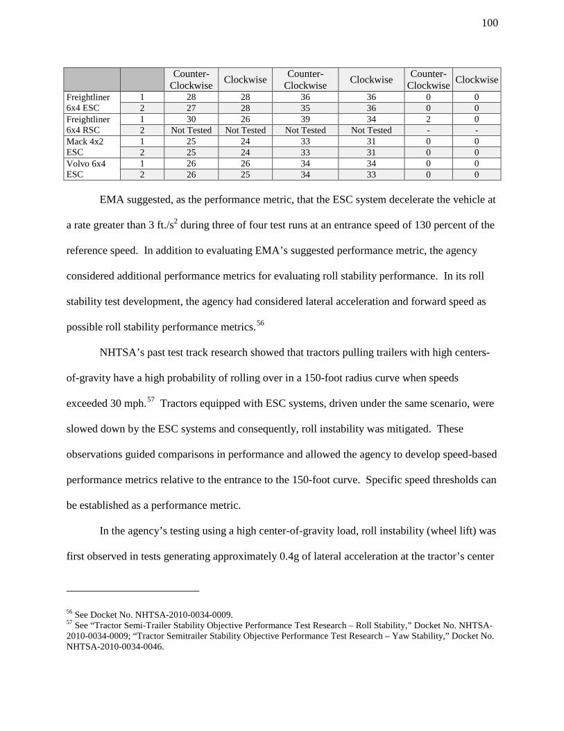
100
Counter-Clockwise Clockwise Counter-
Clockwise Clockwise Counter-Clockwise Clockwise
Freightliner 6x4 ESC
1 28 28 36 36 0 0 2 27 28 35 36 0 0
Freightliner 6x4 RSC
1 30 26 39 34 2 0 2 Not Tested Not Tested Not Tested Not Tested - -
Mack 4x2 ESC
1 25 24 33 31 0 0 2 25 24 33 31 0 0
Volvo 6x4 ESC
1 26 26 34 34 0 0 2 26 25 34 33 0 0
EMA suggested, as the performance metric, that the ESC system decelerate the vehicle at
a rate greater than 3 ft./s2 during three of four test runs at an entrance speed of 130 percent of the
reference speed. In addition to evaluating EMA’s suggested performance metric, the agency
considered additional performance metrics for evaluating roll stability performance. In its roll
stability test development, the agency had considered lateral acceleration and forward speed as
possible roll stability performance metrics.56
NHTSA’s past test track research showed that tractors pulling trailers with high centers-
of-gravity have a high probability of rolling over in a 150-foot radius curve when speeds
exceeded 30 mph.57 Tractors equipped with ESC systems, driven under the same scenario, were
slowed down by the ESC systems and consequently, roll instability was mitigated. These
observations guided comparisons in performance and allowed the agency to develop speed-based
performance metrics relative to the entrance to the 150-foot curve. Specific speed thresholds can
be established as a performance metric.
In the agency’s testing using a high center-of-gravity load, roll instability (wheel lift) was
first observed in tests generating approximately 0.4g of lateral acceleration at the tractor’s center
56 See Docket No. NHTSA-2010-0034-0009. 57 See “Tractor Semi-Trailer Stability Objective Performance Test Research – Roll Stability,” Docket No. NHTSA-2010-0034-0009; “Tractor Semitrailer Stability Objective Performance Test Research – Yaw Stability,” Docket No. NHTSA-2010-0034-0046.

101
of gravity. Wheel lift was generally observed between 3 and 4 seconds after the steering input,
which is when 0.4g of lateral acceleration was sustained. Based on these observations, the
agency set the tractor lateral acceleration thresholds for roll stability during the 150-foot J-turn
maneuver at a maximum of 0.375 g at 3.0 seconds after the vehicle crossed the start gate and
0.350 g at 4.0 seconds after the vehicle crossed the start gate.
However, because the radius of the curved portion of the track is fixed, these lateral
acceleration thresholds can be related to speed thresholds using the formula A=V2/R, where A is
the lateral acceleration, V is the vehicle’s forward speed, and R is the radius of the curve.
Inserting the specified lateral acceleration levels and the radius of the curve, the agency’s lateral
acceleration thresholds converted to maximum speed thresholds of 29 mph and 28 mph at 3.0
and 4.0 seconds, respectively.
Each tractor and stability control system tested exceeded EMA’s suggested 3 ft./s2
minimum deceleration test criteria. Each tractor and stability control system tested also
exceeded NHTSA’s speed and lateral acceleration thresholds.
F. Roll Stability Performance Test -- J-Turn Test
1. Rationale for Using J-Turn Test
NHTSA has decided to substitute the J-turn maneuver in place of the SIS and SWD
maneuvers as the performance test for an ESC system. The J-turn test will be used to evaluate
the roll stability of a vehicle. Likewise, the J-turn will also be used to ensure that the ESC
system reduces engine torque to the wheels. Because the J-turn is conducted on a fixed curve,
longitudinal velocity (speed) directly correlates to lateral acceleration. NHTSA has determined
that the J-turn test is the most cost-effective and least burdensome alternative that achieves the
objectives of the ESC rule. Moreover, the roll stability mitigation performance requirements

102
associated with the J-turn maneuver are comparable to the minimum performance requirements
associated with the SWD maneuver proposed in the NPRM.
To be clear, however, the agency rejects much of the criticism of the SWD maneuver in
the comments from truck manufacturers. Although we are abandoning the proposed SIS and
SWD maneuver in favor of a J-turn maneuver to test roll stability in this final rule, NHTSA still
considers the SWD test to be a viable test to measure the minimum performance of an ESC
system on a heavy vehicle.
We do not agree with the commenters’ assertions about the relevance of the SWD
maneuver. The lack of voluntary adoption of the SWD test by vehicle manufacturers does not,
by itself, make the SWD test irrelevant.
Likewise, the comments regarding the width of public roads and how the maneuver is not
likely to occur on public roads are inapposite. The purpose of the performance test is to
determine the minimum performance requirements of ESC systems using an objective and
repeatable test. The fact that the SWD test will not be performed on public roads and must be
performed on a test track, which can be 6 to 8 lanes of public road width or larger, is not by itself
a persuasive argument that the test is irrelevant.
Nor does the agency agree with the commenters suggesting that additional design work
would be necessary in order for vehicles to meet SWD performance requirement. None of the
commenters suggesting additional design work was necessary submitted information to justify
the assertion. Moreover, Bendix, a system supplier, asserted that current ESC systems could
pass the proposed SWD test. NHTSA’s own testing using two typical 6x4 tractors each
equipped with ESC systems consistently met the proposed performance requirements using the

103
SWD test. In addition, no commenter submitted supporting information describing any specific
design compromises that would occur as a result of complying with the SWD test.
Likewise, the agency does not characterize the testing of saleable vehicles as an
unnecessary cost increase. Contrarily, performing the tests on saleable vehicles, as opposed to
manufacturing a vehicle solely for testing purposes, reduces the amount of cost to a
manufacturer. The manufacturers have provided no basis for their assertions that they could not
resell vehicles after conducting SWD tests. Although they have asserted that the vehicles may be
damaged during testing, NHTSA has not experienced any vehicle damage during its own testing.
In response to Volvo’s claim of potential damage to vehicles being tested, the agency recognizes
that any performance test, if done unsafely, could potentially damage the vehicle being tested.
Nevertheless, NHTSA believes the J-turn test maneuver is more efficient than the SWD
test for assessing the roll instability mitigation of ESC systems. The J-turn test can demonstrate
roll stability using only a single test. There is no need to analyze and extrapolate data between
two separate test maneuvers as there is using the SIS and SWD tests. This will allow the agency
to complete a compliance test more quickly using the J-turn than using the SIS and SWD tests.
We did not receive any estimate from EMA or its members regarding the costs to
perform the J-turn test. However, EMA and its members did not object to the cost of its
suggested performance test, nor did any commenter discuss the difference in cost of the J-turn
test versus the SWD and SIS tests. Instead, the agency received a recommendation from dozens
of commenters to adopt the J-turn test. The agency estimates that it would cost approximately
$13,400 per truck tractor and $20,100 per large bus to conduct the full series of J-turn test
maneuvers contained in this final rule.

104
We also note that the J-turn maneuver is similar to the Ramp Steer Maneuver (RSM),
which was discussed at length in the NPRM. Both maneuvers use a test course with a straight
lane connected to a curved lane. However, the RSM maneuver is an open loop type test, uses an
automated steering controller, and requires conducting an SIS maneuver to determine the
appropriate steering wheel angle for testing. The J-turn is a path-following maneuver and the
vehicle is steered by the driver. We have chosen a path-following maneuver over the fixed-
steering RSM because of track space concerns regarding the SIS maneuver. We believe that the
amount of track space necessary to conduct the SIS maneuver may only be available at one or
two test facilities in the United States. While one of these facilities is readily available to
NHTSA for compliance testing purposes, we recognize that manufacturers may wish to test their
own vehicles as part of their compliance certification.
We emphasize that the adoption of the J-turn maneuver should not in any way diminish
the roll stability performance we have observed from ESC systems. The performance criteria
associated with the J-turn test maneuver in this final rule have been chosen to ensure a level of
roll instability mitigation performance similar to that required to satisfy the SWD maneuver.
Although the test is conducted at a lower speed, the radius of the curve will increase lateral
acceleration to a level that would generate roll instability in vehicles without ESC systems. We
believe that all large trucks and buses equipped with current generation ESC systems will meet
the minimum performance requirements just as we believe they would have met the minimum
performance requirements associated with the SWD maneuver. Therefore, we do not believe
that the use of a different test maneuver will change the expected performance of ESC systems.
We also observe that, like the sine with dwell maneuver, the J-turn maneuver that is one
of the demonstration tests in Annex 21 of UN ECE Regulation 13. If a manufacturer chooses the

105
J-Turn test as a demonstration test to show compliance with Annex 21 and can achieve the
performance criteria established in this final rule, then there would be compatibility between the
performance tests of FMVSS No. 136 and UN ECE Regulation 13.
NTSB provided comments indicating that rollover performance standards should be
measured by static rollover stability. NHTSA does not agree with the NTSB’s suggestion.
NHTSA developed test methods that could evaluate an ESC system’s performance dynamically.
The goal is to create a measure of performance that will ensure that an ESC system could prevent
a rollover. A static stability test would not measure how an ESC system reduces lateral
acceleration to reduce untripped rollovers.
2. Test Procedure and Performance Requirements
The J-turn test procedure developed based on EMA’s suggestion is a sequential
procedure in which the test vehicle is repeatedly driven through a 150-foot radius curve. The test
is conducted on the same test course and is generally performed in the manner suggested by
EMA with only minor changes added to test lateral responsiveness and to test the ESC system’s
ability to reduce engine output. We have also modified the minimum performance criteria to use
forward speed rather than deceleration rate. We found that using deceleration rate as a minimum
performance criteria would not address vehicle wheel lift and subsequent rollover, especially
when the vehicle has a load with a high center-of-gravity. EMA’s suggestion only measures the
braking rate, but it does not measure the ESC system’s capability to lower vehicle lateral
acceleration to an acceptable threshold.
A diagram of the curve is included below. We have also included a diagram in the
regulatory text to clarify any ambiguities in the description of the course, which is included in
Figure 3 below. Although the lane markings are depicted with dots on the figure, there is no

106
specification for how the lane is marked. It may, for example, be marked with cones or painted
lines. Although the figure depicts a counter-clockwise layout, the test is conducted in both
directions.
Figure 3. J-turn Test Maneuver Course (shown with the curved lane section in the counter-clockwise direction)
The start gate is placed at the point of the test course where the straight lane section
intersects with the curved section of the lane. An end gate is placed on the curved portion of the
lane at 120 degrees of arc angle from the start gate. It will take a test vehicle more than 4
seconds to pass through the end gate. Therefore, all of the necessary data will be collected by
that point.

107
For truck tractors, the lane width is 3.7 meters (12 feet) for both the straight section and
curved section of the course. However, large buses require additional lane width on the curved
section of the course because buses have longer wheelbases, which make it substantially more
difficult to maintain a narrower lane within the curve. The large buses that the agency tested did
not physically fit in the curved section of the 12-foot lane because of their long wheelbases.
During testing, the rear wheels of the buses departed the lane even at very low entrance speeds
because of the geometry of the buses, not because of a lack of stability. Therefore, for buses, the
lane width on the curved section of the course is 4.3 meters (14 feet).
Each is subjected to multiple J-turn test runs with a test speed starting at 32 km/h (20
mph) and increased in 1.6 km/h (1 mph) increments until ESC service brake activation is
observed. The test driver will not apply the service brakes or the engine exhaust braking during
the maneuver. For air-braked vehicles, ESC service brake activation occurs when the ESC
system causes the pressure in the service brake system to reach at least 34 kPa (5 psi) for a
continuous duration of at least 0.5 second. For vehicles with hydraulic brakes, ESC service
brake application occurs when the ESC system causes the pressure in the service brake system to
reach at least 172 kPa (25 psi) for a continuous duration of at least 0.5 second. This speed is
considered the Preliminary Reference Speed. This procedure is conducted separately using
clockwise and counterclockwise steering.
The J-turn maneuver is then repeated four times at the Preliminary Reference Speed to
confirm that this is the speed at which ESC service brake activation occurs. To do this, four test
runs are performed and ESC service brake application is verified. If ESC service brake
application is verified, this speed is considered the Reference Speed. If ESC service brake
activation does not occur during at least two of the four test runs, the Preliminary Reference

108
Speed is incremented by 1.6 km/h (1 mph) and ESC service brake application is again verified.
Again, the Reference Speed is determined for both the clockwise and counterclockwise direction.
Once the Reference Speed is determined, the ESC system’s ability to reduce engine
torque is verified. Two series of four test runs (one series clockwise, the other series
counterclockwise) are conducted at the Reference Speed. During these maneuvers, the driver
will fully depress the accelerator pedal after entering the curve and throughout the curve.
NHTSA will verify that the engine torque output is less than the driver-requested output. This
ensures that the driver’s attempt to accelerate the vehicle does not override the ESC service
brake application and verifies the system’s ability to mitigate instability by reducing engine
torque.
Thereafter, the vehicle is subjected to multiple series of test runs (both clockwise and
counterclockwise) at an entrance speed up to a maximum test speed, which is up to 1.3 times the
Reference Speed, but no less than 48 km/h (30 mph). At a speed between 48 km/h (30 mph) and
the maximum test speed, the vehicle is subjected to eight maneuvers, during which ESC service
brake activation is verified. The vehicle must be able to meet the roll stability performance
criteria discussed below at any speed between 48 km/h (30 mph) and the maximum test speed.
3. System Responsiveness
The NPRM described the need for a lateral displacement performance metric because of
the possibility of a manufacturer making the vehicle poorly responsive to the speed and steering
inputs required by the SWD test. The risk of poor lateral displacement in response to the driver’s
steering input was mitigated by a minimum responsiveness criterion. Although the SWD test is
being replaced with the J-turn test, we still need to account for vehicle responsiveness. The

109
nature of the J-turn test provides two criteria for ensuring vehicle responsiveness: Maintaining
the lane within the fixed radius curve and a minimum test speed.
The first responsiveness criterion is the requirement that the vehicle maintain the lane
during at least six of eight runs in the roll performance test series or at least two of four runs in
any other test series. This requirement ensures that, during J-turn test runs at increasing speeds,
the ESC system actually activates before the vehicle becomes unstable. We are not imposing
this requirement for each test run within a series to account for driver variability and possible
driver error in conducting the maneuver. Absent driver error, we do not expect any vehicle
equipped with current-generation ESC systems to leave the lane during any J-turn test.
The other responsiveness criterion in this final rule is the minimum vehicle entry speed of
48 km/h (30 mph) for the roll performance test. This will discourage a manufacturer from
designing a system that will intervene only at very low speeds, thus artificially decreasing the
speed at which the vehicle will enter the curve during the roll performance test.
4. Engine Torque Reduction
As proposed in the NPRM, there must be at least a 10 percent reduction in engine torque
when measured 1.5 seconds after the activation of the ESC system. The percent reduction is
measured between the actual engine torque output and the driver-requested torque input. This
measurement was to be taken during the slowly increasing steer maneuver. However, now that
the agency has adopted the J-turn test as its performance test, the SIS test is no longer necessary.
Accordingly, the agency has modified the engine torque reduction test in the NPRM so
that it can be used with the J-turn test. The reference speed, which is the lowest test speed at
which the ESC system activated the vehicle’s service brakes, is determined as part of the J-turn
test sequence. An additional two test series (one using clockwise steering and the other using

110
counterclockwise steering) are conducted after the reference speed is calculated. The driver then
fully depresses the accelerator pedal after the vehicle crosses the start gate. After ESC activation
occurs, data is collected to determine the difference between the actual engine torque output and
the driver requested torque. After analyzing research data from the J-turn testing, we have
determined that the ESC system must reduce the driver requested engine torque by at least 10
percent for at least 0.5 second during the time period between 1.5 seconds after the vehicle
passes the start gate and when it travels through the end gate. We are not considering reduced
engine torque before 1.5 seconds after the vehicle crosses the start gate (and the driver fully
depresses the accelerator pedal) because our testing has shown that there is a lag between when
the operator of the vehicle requests full throttle and when the vehicle responds by providing full
throttle.
5. Roll Stability Performance Requirements
Based on NHTSA’s research, for a typical combination vehicle, an ESC system must
reduce the heavy vehicle’s lateral acceleration to less than 0.4g to prevent wheel lift and possible
vehicle rollover.58 NHTSA considered how to measure lateral acceleration during the J-turn
maneuver. However, lateral acceleration is a function of longitudinal velocity. Using the
equation A=V2/R, where A is lateral acceleration, V is longitudinal velocity, and R is the radius
of the curve, when driven in a fixed radius curve, with a 45.7-meter (150-foot) radius, 0.4g of
lateral acceleration would be achieved at a forward velocity of approximately 48 km/h (30 mph).
That is, at speeds below 30 mph, a vehicle would generate less than 0.4g of lateral acceleration
and would be unlikely to roll over. This was confirmed in the agency’s testing, where the test
vehicles remained stable at speeds below 30 mph.
58 See 77 FR 30776-78.

111
NHTSA track testing has shown that the minimum test speed for effectively testing the
ESC system is 48 km/h (30 mph). However, where the ESC system activates at a speed such that
1.3 times the minimum activation speed is greater than 48 km/h (30 mph), the vehicle may be
tested at a speed up to 1.3 times the minimum activation speed. A multiplication factor of 1.3
will be used to ensure that ESC systems operate over a range of speeds. A factor of 1.3 allows
the vehicle’s ESC system to reach a level where maximum brake force is applied by the system,
and, as a result, ensures the ESC system reduces the longitudinal velocity and lateral acceleration
of the vehicle are below the threshold values. At factors below 1.3, our testing has shown that
ESC systems have not yet achieved their maximum braking force. At factors above 1.3, we have
concerns about the safety of testing because the ESC systems have achieved their maximum
braking force and the lateral acceleration of the vehicle could remain high.
In contrast, using a performance requirement such as EMA’s suggested minimum
deceleration metric provides no assurance that the deceleration will be sufficient to prevent
rollover. For example, using EMA’s suggested procedure, if a vehicle is able to enter a curve at
a relatively high rate of speed before an ESC system activates, the performance requirement will
be more stringent than if a system is tuned to activate at lower rates of speed. Particularly, if a
test is conducted at an entrance speed of less than 48 km/h (30 mph), the system’s ability to
prevent rollover is not challenged because the vehicle is unlikely to experience lateral forces that
have the potential to cause instability, even if the vehicle was not equipped with an ESC system.
We considered, but rejected, using the lateral acceleration ratio, which was the proposed
performance criteria for both the SWD maneuver and the alternative RSM, rather than the
reduction in absolute lateral acceleration. Using the J-turn maneuver, it was sufficient to ensure
that the absolute lateral acceleration was below the threshold for wheel lift after the vehicle has

112
begun its turn. Furthermore, unlike the SWD and RSM maneuver where the beginning of steer
can be determined, the beginning of the J-turn maneuver occurs when the vehicle crosses the
start gate. At this point, the lateral acceleration of the vehicle is zero or close to zero because the
vehicle is traveling in a straight line. After the vehicle crosses the start gate, the driver has some
discretion for steering the vehicle and maintaining the lane. The low initial lateral acceleration
and the driver variation both make the lateral acceleration ratio an inappropriate performance
metric for the J-Turn test. Instead, we found that reduction in the absolute lateral acceleration of
a vehicle, which on a fixed curve is a function of velocity, was sufficient to determine the
performance of an ESC system with respect to roll stability control.
Thus, the minimum performance requirement to demonstrate roll stability performance in
this final rule is expressed in terms of a vehicle’s forward speed (longitudinal velocity) at two
points in time. The specific requirements are:
• The longitudinal velocity measured at 3.0 seconds after vehicle passes through the start
gate to the J-turn maneuver must not exceed 47 km/h (29 mph).
• The longitudinal velocity measured at 4.0 seconds after vehicle passes through the start
gate to the J-turn maneuver must not exceed 45 km/h (28 mph).
NHTSA’s research indicates than an ESC system’s ability to maintain an absolute lateral
acceleration below the criteria would provide an acceptable probability that the vehicle would
remain stable and that a level of absolute lateral acceleration above the criteria would result in a
high probability of the vehicle becoming unstable.
G. Yaw Stability
NHTSA has decided to defer research on the yaw maneuver suggested by EMA, the
single lane change on a wet surface test. EMA did not provide any data showing how its

113
performance criterion (differential brake pressure) measures the capability of the ESC system to
prevent yaw instability. Moreover, EMA submitted data showing that at least three of its tested
vehicles failed to meet the criteria. NHTSA would need to further research the EMA maneuver
and determine adequate performance metrics. More data is needed to create criteria that
represent appropriate stability thresholds by showing an acceptable probability that the vehicle
would remain stable if the ESC system maintains those criteria.
The SWD maneuver was designed to test the ESC system’s ability to prevent yaw
instability by measuring how quickly the vehicle stops turning, or rotating about its vertical axis,
after the steering wheel is returned to the straight-ahead position. The vehicle that continues to
turn or rotate about its vertical axis under these conditions is most likely experiencing oversteer,
which is what ESC is designed to prevent. EMA’s data does not show how its yaw maneuver
will adequately test the ESC system’s capabilities to prevent oversteer. Likewise, the Bendix
test, a ramp with dwell maneuver, will not be examined by NHTSA at this time for yaw stability
testing. In order to create a performance test, NHTSA would need to do further research on the
Bendix maneuver and determine adequate performance metrics.
We are also concerned that the maneuver is conducted on a low-friction wet Jennite
surface. EMA stated that it disagrees with the statement in the NPRM that low-friction surfaces
such as wet Jennite are too variable to make them unusable for ESC testing. EMA believes that
the use of wet Jennite in FMVSS No. 121 for air-brake testing makes wet Jennite suitable for
ESC testing. However, we remain concerned about the potential for variability in surface
friction on a wet Jennite surface for ESC system testing.
To date, we have found that only the SWD maneuver proposed in the NPRM is suitable
for testing yaw stability, and even that test is limited to testing oversteer. As discussed above,

114
we have decided not to conduct compliance tests on vehicles using the SWD because of the
substantial time and instrumentation burden associated with the SWD maneuver. We do not
believe that this additional time and cost is justified solely to test yaw stability when a majority
of the benefits of this final rule are derived from rollover prevention. Moreover, the SWD
maneuver would only test oversteer mitigation of yaw instability, whereas understeer is the
primary type of yaw instability that we observed in our testing. However, we are continuing to
examine possible yaw performance maneuvers, including the SWD maneuver and the lane
change maneuver suggested by EMA to test yaw stability control performance in the future.
H. Understeer
As we stated in the NPRM, the agency has no performance test to evaluate how the ESC
responds when understeer is induced. The technique used by a stability control system for
mitigating wheel lift, excessive oversteer or understeer conditions is to apply unbalanced wheel
braking so as to generate moments (torques) to reduce lateral acceleration and to correct
excessive oversteer or understeer. However, for a vehicle experiencing excessive understeer, if
too much oversteering moment is generated, the vehicle may oversteer and spin out with obvious
negative safety consequences. In addition, excessive understeer mitigation acts like an anti-roll
stability control where it momentarily increases the lateral acceleration the vehicle can attain.
Hence, too much understeer mitigation can create safety problems in the form of vehicle spin out
or rollover.
During the testing to develop FMVSS No. 126 for light vehicles, the agency concluded
that understanding both what understeer mitigation can and cannot do is complicated, and that
there are certain situations where understeer mitigation could potentially produce safety
disbenefits if not properly tuned. Therefore, the agency decided to enforce the requirements to

115
meet the understeer criterion included in the ESC definition using a two-part process. First, the
requirement to meet definitional criteria ensured that all had the hardware needed to limit vehicle
understeer. Second, the agency required manufacturers to make available engineering
documentation to NHTSA upon request to show that the system is capable of addressing vehicle
understeer.
Based on the agency’s experience from the light vehicle ESC rulemaking and the lack of
a suitable test to evaluate understeer performance, the agency did not propose a test for
understeer to evaluate ESC system performance for truck tractors and large buses. The agency
sought comment on the lack of an understeer test.
Advocates stated in its comment that there should be a compliance test for understeer
performance. It said the ESC equipment requirement for understeer is not enough to ensure
sufficient performance to mitigate understeer conditions.
While we agree with the Advocates goal of having an understeer test, we have not been
able to develop a test that safely challenges an ESC system’s ability to mitigate understeer.
Moreover, we believe the definitional criteria are robust enough to ensure that an ESC system
will reduce loss-of-control crashes in both understeer and oversteer conditions.
XI. Test Conditions and Equipment
A. Outriggers
Throughout the agency’s research program, truck tractors and buses were equipped with
outrigger devices to prevent vehicle rollover. During the program, the agency encountered many
instances of wheel lift and outrigger contact with the ground indicating that it was probable that
rollover could occur during testing. Over many years of research of ESC systems, it has been

116
proven that outriggers are essential to ensure driver safety and to prevent vehicle and property
damage during NHTSA’s compliance testing. Although NHTSA conducted some of its testing
with ESC systems disabled, thereby increasing the need for outriggers, outriggers are still
necessary as a safety measure during testing of vehicles equipped with an ESC system in case the
system fails to activate.
The agency proposed that outriggers be used on all truck tractors and buses tested. We
believe that outrigger influence on heavy vehicles is minimal because of the higher vehicle
weight and test load. To reduce test variability and increase the repeatability of the test results,
the agency proposed to specify a standard outrigger design for the outriggers that will be used for
compliance testing. The agency used this same approach in FMVSS No. 126 for compliance
testing of light vehicle ESC systems. The agency also made available the detailed design
specifications by reference to a design document located in the agency public docket.
For truck tractors, the document detailing the outrigger design to be used in testing has
been placed in a public docket.59 This document provides detailed construction drawings,
specifies materials to be used, and provides installation guidance. For truck tractor
combinations, the outriggers are mounted on the trailer. The outriggers are mounted mid-way
between the center of the kingpin and the center of the trailer axle (in the fore and aft direction of
travel), which is generally near the geometric center of the trailer. They will be centered
geometrically from side-to-side and bolted up under the traditional flatbed control trailer. Total
weight of the outrigger assembly, excluding the mounting bracket and fasteners required to
mount the assembly to the flatbed trailer, is less than 2,500 pounds. The bulk of the mass is for
the mounting bracket which is located under the trailer near the vehicle’s lateral and longitudinal
59 Docket No. NHTSA-2010-0034-0010.

117
center of gravity so that its inertial effects are minimized. The width of the outrigger assembly is
269 inches and the contact wheel to ground plane height is adjustable to allow for various
degrees of body roll. A typical installation on a flatbed type trailer involves clamping and
bolting the outrigger mounting bracket to the main rails of the flatbed.
The NPRM proposed that the outrigger design have a maximum weight of 726 kg (1,600
lb.). However, the agency raised the weight limit of the outriggers used for testing to
accommodate the use of older and heavier outrigger designs. This final rule raises the maximum
weight of the outriggers to 1,134 kg (2,500 lb.).
For buses, the outrigger installations will not be as straightforward as the outrigger
installations on the control trailers, and the NPRM solicited comments on bus outrigger designs.
This is because outriggers cannot be mounted under the flat structure, but instead must extend
through the bus. NHTSA used outriggers on the three large buses tested during its research
program and will use outriggers for testing buses for compliance with this rule. The agency
plans to use the same outrigger arms of the standard outrigger design that it plans to use for truck
tractor testing. Therefore, the size, weight, and other design characteristics will be similar.
The location and manner of mounting the outriggers on buses cannot be identical to truck
tractors. Nonetheless, there are a limited number of large bus manufacturers, which results in a
limited number of unique chassis structural designs. Also, the agency understands that large bus
structural designs do not change significantly from year-to-year. We believe that once outrigger
mounts have been constructed for several different bus designs, those mountings can be modified
and reused during subsequent testing. The agency has, in the document described above,
provided additional engineering design drawings and further installation guidelines for installing
the standard outrigger assemble to large buses.

118
B. Automated Steering Machine
The NPRM proposed using an automated steering machine be used for the test
maneuvers on the truck tractors and large buses in an effort to achieve highly repeatable and
reproducible compliance test results. In the SWD maneuver, the steering must follow an exact
sinusoidal pattern over a three-second time period. For the SWD maneuver, each test vehicle is
subjected to as many 22 individual test runs all requiring activation at a specific vehicle speed,
each of which will require a different peak steering wheel angle and corresponding steering
wheel turning rate.
However, the agency has chosen the J-turn maneuver for the performance test. Although
the SWD test requires a fixed steering wheel angle, the J-turn test is a path-following maneuver.
This means a steering controller will not be required for the J-turn test because the driver
provides the steering wheel input in order to keep the vehicle within the lane during the test
maneuver.
Because the driver must attempt to keep the vehicle within the lane width, he has some
discretion on the steering wheel angle and the position of the vehicle within the lane as the
vehicle crosses the start gate. Depending on the experience and technique of the driver, the
vehicle may have a steering wheel angle that is varied by the time the vehicle crosses the start
gate. This variance is tolerable because we do not expect that it will be difficult for a
professional test driver to maintain the vehicle lane. Nevertheless, to ensure that variability in
testing does not affect vehicle compliance, the performance requirements need only be satisfied
during two out of four runs of a test series (or six out of eight runs of the final series).

119
C. Anti-Jackknife System
The agency proposed using an anti-jackknife system when testing truck tractors. An anti-
jackknife system prevents the trailer from striking the tractor during testing in the event that a
jackknife event occurs during testing. This would prevent damage to the tractor that may occur
during testing. We do not believe that the use of an anti-jackknife system will affect test results,
nor have we observed any damage to test vehicles, including vehicle finishes, caused by anti-
jackknife cables.
The agency proposed using cables to limit the angle of articulation between the truck
tractor and trailer, and set a minimum angle of 45 degrees because setting the cables too tight
could artificially help the ESC system maintain control during testing. However, if the angle of
articulation is set too low the turning radius of the combination vehicle decreases to a point
where maneuverability of the vehicle becomes an issue. A vehicle with too low of a turning
radius would not be able to drive through the J-turn test course. Therefore, we must to set a
minimum articulation angle for the jackknife system that ensures safety during testing, but is not
too low such that it would affect test results. However, our testing has shown that 45 degrees is
too high of an angle for a 4x2 truck tractor, because the trailer could still contact the truck
tractor. Therefore agency is specifying 30 degrees as the minimum articulation angle in this
final rule, which is sufficient to provide safety during the testing of all truck tractors.
D. Control Trailer
The agency proposed using a control trailer to evaluate the performance of a truck tractor
in the loaded condition. In FMVSS No. 121, the agency specifies the use of an unbraked control
trailer for compliance testing purposes. An unbraked control trailer minimizes the effect of the
trailer’s brakes when testing the braking performance of a tractor in its loaded condition.

120
Nevertheless, in the NPRM, we identified potential variability in the control trailer that affected
the repeatability of SWD testing and asked for comments on how the control trailer may be
specified to prevent variability.60
Navistar and EMA commented on a specific truck tractor that satisfied the proposed
SWD criteria with the ESC system disabled. We believe this is “Vehicle J” that was identified in
the NPRM. NHTSA conducted its own testing on “Vehicle J” using a different control trailer.
In contrast to EMA’s test results, NHTSA’s testing showed that Vehicle J became laterally
unstable with the ESC system disabled.
Volvo, EMA, Advocates, and Bendix commented on the control trailer specifications.
Volvo asserted that further specifications need to be made for the control trailer because trailer
configuration greatly affects compliance of the SWD test. EMA stated that the control trailer’s
track width, deck height, ballast, suspension, tires and torsional stiffness affect the SWD test
results, and small variations in the control trailer influence the SWD testing. EMA further
indicated that would not be practical to build trailers with stricter design specifications in order
to perform SWD tests and obtain consistent results. Conversely, Advocates and Bendix
recommended that the agency add new specifications and tighten up existing requirements in
order to reduce the variability in testing. Advocates recommended specifying track width, trailer
CG height, and load CG height in the standard because it would minimize variation in testing.
Other than soliciting comments in the NPRM, the agency did not investigate whether
variations in the control trailer significantly affect the results of the SWD maneuver. However,
60 There were three specifications, not set forth in control trailer specifications in FMVSS No. 121, that the agency identified that might affect SWD test performance and prevent repeatable, consistent test results using different control trailers. First, the track width of the control trailer is not specified. Second, the center of gravity of the control trailer is not specified. Third, the center of gravity of the load in FMVSS No. 121 testing is only specified to be less than 24 inches above the top of the tractor’s fifth wheel.

121
the agency has not further modified the specifications of the control trailer. Rather, we believe
that, by using the J-turn maneuver rather than the SWD maneuver, any potential test variability
caused by different control trailers is ameliorated. The agency’s research shows that, because the
performance metric is vehicle speed rather than lateral acceleration ratio, the effect that the
control trailer has on the lateral acceleration is negligible. The sole consideration in the
performance criteria in this final rule is speed reduction, which has not been observed to be
affected by variations in the control trailer.
We note that Volvo, EMA, and Bendix recommended the adoption of the J-turn test,
which is one of the alternative tests discussed in the NPRM. None of the commenters supporting
adoption of the J-turn test raised issues regarding variability in the control trailer with the J-turn
maneuver. Rather, their comments regarding control trailer variability were limited to the SWD
test maneuver.
Further, the agency conducted J-turn testing using two different control trailers. We did
not find any relevant differences in the ESC system performance of the truck tractors when
connected to different control trailers. We believe, based on our testing and the lack of
comments related to the control trailer in the J-turn maneuver, that the potential for variability
identified in the NPRM related to the control trailer was limited to the SWD maneuver. We
conclude that the factors identified in the NPRM will have no effect on the performance of
vehicles using the J-turn maneuver.
Volvo also commented that the control trailer specified in FMVSS No. 121 will not work
with four or more axle tractors such as 8x6 truck tractor’s because the trailer’s fifth wheel
position causes interference between the tractor frame and trailer frame. NHTSA has considered
this comment and believes that there is merit in Volvo’s assertion. A control trailer at the length

122
specified in the NPRM of 6550 ± 150 mm (258 ± 6 in) may be too short to test vehicles with four
or more axles. In this final rule, we are changing the specified length of the control trailer to
allow for testing with a longer trailer. We are specifying that truck tractors will be tested with a
control trailer that is between 6400 mm and 7010 mm (252 in and 276 in), inclusive. However,
for truck tractors with four or more axles, at the manufacturer’s option, NHTSA will test with a
control trailer with a length up to 13,208 mm (520 in). We do not believe that using a control
trailer longer than that specified in the proposal would cause variability in testing.
E. Sensors
The vehicle speed is measured with a non-contact GPS-based speed sensor. Accurate
speed data is required to ensure that the SWD maneuver is executed at the required 72.4 + 1.6
km/h (45.0 + 1.0 mph) test speed. Sensor outputs are available to allow the driver to monitor
vehicle speed.
F. Ambient Conditions
The ambient temperature range specified in other FMVSSs for outdoor brake
performance testing is 0 °C to 38 °C (32 °F to 100 °F). However, when the agency proposed a
range of 0 °C to 40 °C (32 °F to 104 °F) for FMVSS No. 126, the issue of tire performance at
near freezing temperatures was raised. The agency understood that near freezing temperatures
could impact the variability of compliance test results. As a result, the agency increased the
lower bound of the temperature range to 7 °C (45 °F) to minimize test variability at lower
ambient temperatures. For the same reasons, the NPRM proposed an ambient temperature range
of 7 °C to 40 °C (45 °F to 104 °F) for testing.
In their comments, Meritor WABCO, EMA, and Bendix recommended changes to the
minimum ambient temperature allowed for testing. The three commenters requested that the

123
minimum temperature for performance tests to be reduced. Meritor WABCO recommended a
minimum temperature of 2 °C (35 °F). Both EMA and Bendix recommended a minimum
temperature of 0 °C (32 °F). EMA asserted that the minimum temperature of 7 °C (45 °F)
proposed in the NPRM reduces the amount of time available to test vehicles during the year. We
agree that a minimum test temperature of 7 °C (45 °F) restricts the agency’s ability to test for
compliance in certain areas of the United States, including NHTSA’s Vehicle Research and Test
Center in Ohio. Thus, we are lowering the minimum testing temperature to 2 °C (35 °F). We
believe this change will have a negligible effect on the outcome of performance testing.
EMA further recommended that the upper limit be decreased from 40 °C (104 °F) to 38
°C (100 °F) to match the FMVSS No. 121 ambient temperature specifications. We are not
adopting this suggestion to match the temperature specifications in FMVSS No. 121. EMA gave
no reason other than consistency with FMVSS No. 121 for adopting this change. Allowing for a
larger temperature range for testing ESC systems does not have any effect on the agency’s ability
to conduct consecutive FMVSS No. 121 and FMVSS No. 136 tests because the FMVSS No. 121
testing is conducted at an ambient temperature of not greater than 38 °C (100 °F). Thus,
compliance testing will be conducted at any temperature between 2 °C (35 °F) and 40 °C (104
°F). The agency proposed a maximum wind speed for conducting the compliance testing of no
greater than 5 m/s (11 mph). This is the same value specified for testing multi-purpose
passenger vehicles (MPVs), buses, and trucks under FMVSS No. 126. This is also the same
value used for compliance testing for FMVSS No. 135, Light Vehicle Brake Systems.
As for other ambient conditions, Bendix recommended that the maximum wind speed be
raised from 11 mph (5 m/s) to 22 mph (10 m/s). Bendix did not specify any rationale for

124
wanting the increase in the allowable wind speed. The agency sees no reason to increase the
wind speed at this time.
G. Road Test Surface
The NPRM proposed that the SWD maneuver be executed on a high friction surface with
a peak friction coefficient (PFC) of 0.9, which is typical of a dry asphalt surface or a dry concrete
surface. As in other standards where the PFC is specified, we proposed that the PFC be
measured using an ASTM E1136 standard reference test tire in accordance with ASTM Method
E1337-90, at a speed of 64.4 km/h (40 mph), without water delivery. We proposed incorporating
these ASTM provisions into the standard.
Although we have changed the performance test maneuver, we have not changed the
specifications for the road test surface. The J-turn maneuver is conducted on a high friction
surface with a PFC of 0.9. Thus, we are incorporating the relevant ASTM provisions into this
standard.
Bendix recommended adding a restriction that there be no ice or snow buildup on the test
track surface. NHTSA has not adopted this suggested change. We believe that the surface PFC
specification of 0.9 already ensures that the test track will be free of snow and ice.
H. Vehicle Test Weight
The agency proposed that truck tractors be tested with the combined weight of the truck
tractor and control trailer be equal to 80 percent of the tractor’s GVWR. To achieve this load
condition, we proposed that the tractor be loaded with the fuel tanks filled to at least 75 percent
capacity, test driver, test instrumentation, and ballasted control trailer with outriggers. The
center of gravity of all ballast on the control trailer was proposed to be located directly above the
kingpin. When possible, load distribution on non-steer axles will be in proportion to the tractor’s

125
respective axle GAWRs. Load distribution will be adjusted by altering fifth wheel position, if
adjustable. In the case where the tractor’s fifth wheel cannot be adjusted so as to avoid
exceeding a GAWR, ballast will be reduced so that axle load equals specified GAWR,
maintaining load proportioning as close as possible to specified proportioning.
In its comments, EMA recommended changing the loading requirements from 80 percent
of the truck tractor’s GVWR to 100 percent of the truck tractor’s GVWR requirements. EMA
wanted this loading condition because it is used in FMVSS No. 121 testing, and it would
eliminate the burden of changing the vehicle’s load when going from FMVSS No. 121 testing to
FMVSS No. 136 testing.
In light of the change to the J-turn maneuver, we have determined that the vehicle should
be tested at its GVWR rather than 80 percent of the truck tractor’s GVWR. The agency
proposed SWD testing at 80 percent of GVWR because it was determined that such a weight
would enable the agency to evaluate both roll and yaw stability with a single maneuver. The J-
turn maneuver is designed to evaluate only roll stability, and testing the vehicle at its GVWR is
the most severe configuration for the maneuver. Thus, the agency can use the same loading
condition that it uses for FMVSS No. 121 testing.
EMA also suggested removing the proposed test condition that the fuel tank be 75
percent full. EMA reasoned that high fuel volume is dangerous for testing. Also, EMA
observed that a 75% fuel filling condition is not included in FMVSS No. 121.
Regarding the fuel tank filling, NHTSA specifies the 75 percent fuel level in FMVSS No.
126 for testing light vehicles. The goal of the fuel level specification in FMVSS No. 126 was to
ensure consistent vehicle test weights for the performance tests. With the adoption of the J-turn
maneuver, NHTSA did not find any evidence of varying fuel levels affecting the results of the

126
ESC performance tests. Therefore, NHTSA agrees with EMA and will remove the specification
of a minimum fuel tank level.
The agency proposed that liftable axles be in the down position for testing. This was
because we proposed to conduct our performance test in a loaded condition. Although the
NPRM proposed to load the truck tractor to 80 percent of its GVWR, we believed that a truck
tractor would operate with liftable axles in the down position. In the final rule, we are testing
vehicles at GVWR. Consequently, we will test vehicles equipped with liftable axles in the down
position. This is consistent with the test conditions for testing fully loaded air braked vehicles
under FMVSS No. 121.
For testing buses, the agency proposed loading the vehicle to a simulated multi-passenger
configuration. For this configuration the bus would be loaded with the fuel tanks filled to at least
75 percent capacity, test driver, test instrumentation, outriggers and simulated occupants in each
of the vehicle’s designated seating positions. The simulated occupant loads would be obtained
by securing 68 kilograms (150 pounds) of ballast in each of the test vehicle’s designated seating
positions without exceeding the vehicle’s GVWR and GAWR. The 68 kilogram (150 pound)
occupant load was chosen because that is the occupant weight specified for use by the agency for
evaluating a vehicle’s load carrying capability under FMVSS Nos. 110 and 120. During loading,
if any rating is exceeded the ballast load would be reduced until the respective rating or ratings
are no longer exceeded.
In the final rule, we have removed the specification that the ballast consists of water
dummies. We do not believe that it is necessary to specify the type of ballast in the test
procedure. We note that, for truck tractors, the type of ballast that is loaded on the control trailer
is not specified. We do not believe, especially in light of the change to the J-turn test, that the

127
type of ballast used (whether it is water, sand, or some other ballast) would have an effect on the
ESC system’s ability to lower the vehicle’s forward speed.
Unlike in the NPRM, this final rule specifies that buses are tested at its GVWR. This is
the most severe loading condition for testing buses using the J-turn test maneuver. The NPRM
specified that buses would be tested with a simulated full passenger load, without any cargo
other than test equipment. We have increased the testing load, which makes the load condition
consistent with the loading NHTSA uses to test FMVSS No. 121 compliance. We have added
specification to the loading procedure to allow for the vehicle to be loaded to GVWR. First,
simulated passengers are loaded. Next, ballast is added to the lowest baggage compartment. If
the bus does not have a baggage compartment or additional ballast is needed because the
baggage compartment is loaded to capacity, ballast is added to the floor of the passenger
compartment to load the bus to its GVWR. During loading, if any axle rating is exceeded, the
ballast is reduced in the reverse order it is loaded until the GVWR or GAWR of any axle is no
longer exceeded.
I. Tires
We proposed testing the vehicles with the tires installed on the vehicle at time of initial
vehicle sale. The agency’s compliance test programs generally evaluate new vehicles with new
tires. Therefore, we proposed that a new test vehicle have less than 500 miles on the odometer
when received for testing.
For testing, the agency proposed that tires be inflated to the vehicle manufacturer’s
recommended cold tire inflation pressure(s) specified on the vehicle’s certification label or the
tire inflation pressure label. We will not change the vehicle’s tires during testing unless test

128
vehicle tires are damaged before or during testing. We did not propose using inner tubes for
testing because we have not seen any tire debeading in any test.
Before executing any test maneuvers, the agency proposed to condition tires to wear
away mold sheen and achieve operating temperatures. To begin the conditioning the test vehicle
would be driven around a circle 46 meters (150 feet) in radius at a speed that produces a lateral
acceleration of approximately 0.1g for two clockwise laps followed by two counterclockwise
laps.
EMA asserted that there should be no requirement for testing using the tires installed on
the vehicle at the time of initial sale. According to EMA, sometimes a test vehicle is used for
certifying compliance, but sometimes a vehicle that is later sold to a customer is tested. Further,
EMA notes that heavy truck manufacturers often offer hundreds of different tire options for their
customers. EMA notes that different tires would change the road adhesion and cornering
stiffness, potentially affecting test results.
Finally, EMA recommended using language from FMVSS No. 121 for the tire inflation
procedure specified by manufacturer for the vehicle’s GVWR, instead of the procedure proposed
in the NPRM, which is to use the vehicle’s certification label or tire inflation pressure label.
EMA reasoned that the actual tires installed on the vehicle may differ from the specifications
given on the label.
First, inasmuch as EMA is referring to the tires used for certifying compliance, we note
that our regulations do not specify how manufacturers certify compliance. We recognize that
some manufacturers do wish to base their certification of compliance on a vehicle’s performance
in NHTSA’s test maneuvers. However, there is no obligation for manufacturer’s to conduct
NHTSA’s compliance test for any vehicle, much less for every possible tire combination. For

129
instance, manufacturers currently certify that their vehicles meet the minimum stopping distance
and ABS requirements of FMVSS No. 121. They must satisfy those requirements for any
vehicle-tire combination that is sold. That is, manufacturers have an obligation to certify
compliance with all applicable standards in whatever configuration that tires are delivered to
customers. We expect that manufacturers design their ESC systems to account for any potential
differences in tires that might be installed on the vehicle at the time of initial sale.
However, with respect to the tire inflation pressure at which testing will be conducted, we
agree with EMA that we should not use the inflation pressure specified on the vehicle’s
certification or tire information labels. As EMA observes, a heavy truck may be sold with many
different tire combinations. However, nothing requires that all of those combinations be listed
on the certification or tire information label.61 However, multiple combinations may be listed on
the label. Thus, we are removing from the regulatory text the reference to the vehicle’s
certification or tire information label and merely specifying that the tires’ inflation pressure will
be the inflation pressure specified for the GVWR of the vehicle.
Regarding tire conditioning, Bendix requested clarification of whether the presence of a
tire conditioning procedure means that the vehicle must be equipped with new tires. Bendix also
recommended that the agency remove this section about the removal of mold sheen because by
performing the brake conditioning test procedure, the same result is likely to be achieved.
To clarify, the agency is not specifying that new tires must be installed prior to the ESC
testing. However, in the event the vehicle has not been driven prior to testing (for example, a
FMVSS No. 121 compliance test has not been performed), we do not believe that the brake
61 In fact, S5.1.2 of FMVSS No. 120, the standard that provides for tire information labeling on vehicles over 10,000 pounds GVWR, expressly contemplates that a vehicle may be sold with a tire size designation that is not listed on the tire information label.

130
burnishing procedure is sufficient to wear away any mold sheen on the tire prior to ESC testing.
Therefore, the requirement to perform four laps is necessary for the consistency and repeatability
of the ESC tests. We do not believe that this procedure is especially burdensome, even if the
mold sheen was removed during prior testing.
J. Mass Estimation Drive Cycle
Both truck tractors and large buses experience large variations in payload mass, which
affects a vehicle’s roll and yaw stability thresholds. To adjust the activation thresholds for these
variations, stability control systems estimate the mass of the vehicle after ignition cycles, periods
of static idling, and other driving scenarios. To estimate the mass, these systems require a period
of initial driving.
The agency proposed including a mass estimation drive cycle as a part of pre-test
conditioning. To complete this drive cycle the test vehicle is accelerated to a speed of 64 km/h
(40 mph), and then, by applying the vehicle brakes, decelerated at 0.3g to 0.4g to a stop.
Meritor WABCO requested that the mass estimation drive cycle procedure be made
manufacturer-specific. That is, Meritor WABCO requested that the procedure be changed to
specify that NHTSA would contact the ESC system supplier for a mass estimation procedure.
Although we specified a mass estimation procedure in the NPRM, that procedure is based
on current ESC system designs. We recognize that system designs could change or new
suppliers could enter the market with different designs that estimate vehicle mass differently.
Thus, we accept Meritor WABCO’s request that NHTSA not specify a mass estimation cycle.
However, we do not agree with Meritor WABCO’s suggestion that NHTSA contact the
ESC system supplier for the mass estimation cycle. It is the vehicle’s manufacturer that is
ultimately responsible for certifying compliance with the FMVSSs. Thus, we believe it is the

131
vehicle’s manufacturer, not the ESC system supplier, who should be responsible for supplying
NHTSA with the mass estimation cycle procedure. Thus, we expect that the vehicle
manufacturer will be able to provide the mass estimation cycle procedure to NHTSA upon
request in advance of any compliance testing.
K. Brake Conditioning
Heavy vehicle brake performance is affected by the original conditioning and
temperatures of the brakes. We believe that incompletely burnished brakes and excessive brake
temperatures can have an effect on ESC system test results, particularly in the rollover
performance testing, because a hard brake application may be needed for the foundation brakes
to reduce speed to prevent rollover.
The agency proposed that the burnish procedure specified in S6.1.8 of FMVSS No. 121
be conducted prior to ESC system testing. The burnish procedure is performed by conducting
500 brake snubs62 between 40 mph and 20 mph at a deceleration of 10 fps2. If the vehicle has
already completed testing to FMVSS No. 121, the agency did not propose to repeat the full
burnishing procedure. Instead, the brakes are conditioned for ESC system testing with 40 snubs.
The agency proposed that the brake temperatures be in the range of 65 °C to 204 °C (150 °F to
400 °F) at the beginning of each test maneuver. We also proposed that the brake temperature be
measured by plug-type thermocouples installed on all brakes and that the hottest brake be used
for determining whether cool-down periods required.
We received no comment on the burnishing procedure and are adopting the proposed
procedure in this final rule, with two exceptions. First, in the NPRM, we proposed to repeat the
FMVSS No. 121 burnish procedure at the manufacturer’s option. However, in this final rule, we
62 A snub is a brake application where the vehicle is not braked to a stop but to a lower speed.

132
have removed the option. Rather, we are merely specifying that a burnish procedure similar to
the one in FMVSS No. 121 be completed prior to testing. Furthermore, rather than referencing
FMVSS No. 121, we have included the entire burnishing in FMVSS No. 136 to avoid the need to
cross-reference between Standards. Second, we have altered the metric conversion of 150 °F
from 65 °C to 66 °C to be more accurate.
In the NPRM, the agency suggested, as a general rule, that a new test vehicle have less
than 500 miles on the odometer when received for testing. EMA commented on this suggestion,
requesting that there be no odometer requirements on a test vehicle. EMA believes that this
requirement may require transporting the test vehicle by hauling it on a trailer to the test site if
the test site is located far away from the place of manufacture. NHTSA agrees with EMA that it
is not feasible to require that a test vehicle have less than 500 miles on its odometer prior to
testing. This is particularly true in light of the burnishing procedure, which could itself require
500 miles of driving. Thus, the final rule does not have a mileage requirement for test vehicles.
L. Compliance Options
Both Bendix and Volvo requested clarification of the proposed regulatory text specifying
compliance options. That provision would require that a manufacturer identify which
compliance option was selected for compliance test purposes and provide that information to the
agency upon request. Bendix and Volvo raised this issue because they did not believe that any of
the proposed requirements offered manufacturers any compliance options to choose from.
In this final rule, we are giving manufacturers a compliance option with respect to the
length of the control trailer used for testing truck tractors. As discussed in section XI.D,
manufacturers of truck tractors with four or more axles may, at the manufacturer’s option, have

133
testing conducted with a longer control trailer. Thus, we are retaining the language requiring
manufacturers to specify compliance options prior to agency testing.
M. Data Collection
In the NPRM, we proposed that the collection of data from the vehicle, such as engine
torque output and driver-requested torque, come from the SAE J1939 communication data link.
Bendix requested that NHTSA change the collection procedure to specify that the data come
from the vehicle controller area network (CAN) bus, which is a more generic reference instead of
specifically requiring a SAE J1939 data link. The CAN bus is what allows a vehicle’s electronic
control units and other devices to communicate with each other. SAE J1939 is a recommended
practice to standardize vehicle communications. Bendix believes that citing SAE J1939
specifically may have the effect of limiting vehicle design in the future.
We agree with Bendix that the reference to SAE J1939 should be changed to a more
generic reference. This will allow future technological advances regarding in-vehicle
communications, including the adoption of new industry recommended practices. Accordingly,
we are specifying that data be collected from the vehicle’s communication network or CAN bus.
Bendix also commented upon the filtering of engine torque data received from an analog
signal. Bendix noted that data from an SAE J1939 compliant communication network is digital
data. However, because we are removing the references to SAE J1939 in response to Bendix’s
comment, we are not changing the procedure for filtering analog data signals because recognize
that some communication systems could use analog signals.

134
XII. ESC Disablement
A. Summary of Comments
In the NPRM, the agency considered allowing a control for the ESC to be disabled by the
driver. Because, heavy vehicles currently equipped with ESC systems do not include on/off
controls for ESC that allow a driver to deactivate or adjust the ESC system, the agency did not
propose allowing an on/off switch for ESC systems. The agency sought public comment on the
need to allow an on/off switch, and asked that commenters specifically address why
manufacturers might need such a switch and how manufacturers would implement a switch in
light of the ABS requirements.
Temsa and Advocates opposed allowing the disablement of the ESC system. They stated
that the ESC system should not be allowed to be deactivated by a switch because the driver may
inadvertently forget to reactivate the system.
In contrast, Daimler, Volvo, Meritor WABCO, HDBMC, Associated Logging, EMA, and
Bendix recommended that we allow the ESC systems to be disabled. The commenters asserted
that the ESC system may need to be disabled in certain conditions such as slippery roads in snow
and mud, off-road operation, and when using snow chains on the tires.
Daimler stated in its comment that the current ESC and traction control systems are
interlinked, and the disablement of traction control will disable ESC systems. Daimler asserted
that disabling traction control may be necessary in conditions such as starting from rest on sloped
ground, driving on slippery roads, and using snow chains. HDBMC also asserted that ESC
disablement is needed for gaining traction in snow and mud and to provide optimum
performance when using snow chains. Meritor WABCO similarly referred to the need for the
ability to change the control scheme of the ESC system to allow for deep snow and mud.

135
In contrast, Bendix stated that its ESC system is tuned for both on-road and mild off-road
conditions. However, Bendix suggested that different vehicle tuning may be necessary for
severe off-road conditions.
Regarding the absence of ESC disablement on current truck tractors, EMA also suggested
that some small volume tractors are more likely to need to have an ESC disablement function for
off-road operation and claimed that at least one manufacturer had equipped a vehicle with such a
switch to temporarily disable ESC. Further, EMA suggested that ESC disablement functions are
not prevalent because large fleet customers have been purchasing ESC systems.
HDMBC recommended that vehicles that have a switch to disable ESC systems be
equipped with a lamp indicating that the ESC system is off similar to the ESC Off telltale in
FMVSS No. 126. In its comment, Meritor WABCO suggested that the ESC malfunction lamp
should be constantly illuminated if ESC is deactivated.
Meritor WABCO, HDBMC, Bendix, EMA, and Volvo also suggested that vehicles be
allowed to automatically disable their ESC systems under certain conditions. Meritor WABCO
claimed that all-wheel drive is an example of when ESC should automatically be disabled.
HDBMC, EMA, and Bendix said there should be the ability to automatically disable ESC system
for certain applications such as all-wheel drive and truck tractors with multiple steering axles.
Volvo asserted that, while it has no plans to offer an ESC on/off switch, it recognizes that some
customers may want to convert a truck tractor to a truck. Volvo believes that it may be
preferable to allow an ESC off switch rather than having converters disabling the ESC system
during a conversion.
In its comment, Bendix also recommended changing the minimum speed at which an
ESC system is required to operate from 20 km/h (12.4 mph) to 25 km/h (15.5 mph) to

136
accommodate the wide variation of tires sizes, tone ring tooth counts, and production tolerances.
Bendix said the higher speed threshold is necessary based on wheel-speed sensor signal strength
and antilock braking system functionality.
B. Response to Comments
This final rule does not allow a function to disable an ESC system at speeds where ESC
systems are required to operate.
First, we address the integration between traction control systems and ESC systems.
Both systems use the vehicle’s brake control system to accomplish different goals. Traction
control reduces engine power and applies braking to a spinning drive wheel in order to transfer
torque to the other drive wheel on the axle. This function is used to allow a vehicle to move
forward in certain conditions where wheel spin may otherwise prevent forward movement. In
contrast, ESC systems are designed to maintain roll and yaw stability rather than facilitate
forward movement.
While we agree that traction control may need to be disabled in slippery conditions such
as snow or mud or other off-road conditions, the commenters do not explain why ESC functions
must be disabled in those circumstances. Although ESC may share components with traction
control, the requirements for ESC are independent of those for traction control. As explained
above, ESC mitigates roll and yaw instability of the vehicle by reducing lateral acceleration and
maintaining directional control, respectively. Although traction control provides mobility in
starting on slippery surfaces, it does not improve lateral stability beyond what ESC provides
through braking and reduction in engine torque. Likewise, traction control does not improve
yaw stability by providing directional control. Traction control provides no further assistance
when lateral or yaw instability is detected.

137
Furthermore, we are not requiring the ESC system to activate at extremely low vehicle
speeds, which is when the vehicle would be starting from rest. This concern may be remedied by
optimizing traction control, and a manufacturer has the option to activate traction control or
allow deactivation of traction control at any vehicle speed. If the disablement of traction control
also disables the ESC system, then the disablement function is prohibited from disabling ESC
functionality at speeds above the minimum speed ESC systems are required to operate. This
means that the ESC system must automatically reactivate once the vehicle reaches the minimum
speed at which the ESC system is required to operate.
Some of the commenters asserted the need for ESC disablement on vehicles with all-
wheel-drive or multi-steering axles. In FMVSS No. 126, we allow the ESC to be disabled on
light vehicles for certain four-wheel drive modes. None of the commenters asserted any
similarities that truck tractors and large buses have with light vehicles regarding enhanced
traction modes such as four-wheel drive low. Therefore, we do not believe any exceptions
should be made for all-wheel drive vehicles because there was insufficient data submitted to
justify an exception for heavy vehicles.
With regard to vehicles with multiple steering axles, we received no specific information
about the vehicle operation and why vehicle with multiple steer axles should be allowed to have
their ESC systems disabled either by switch or automatically. Without any information, the
agency cannot justify an exception.
Regarding off-road use, Bendix and Meritor WABCO discussed ESC tuning differences
between on-road and off-road uses in their comments. However, neither supplier provided
detailed reasons for why ESC system disablement would be beneficial when used in off-road

138
circumstances. In contrast, Bendix said the off-road situations need ESC disablement at low
speeds and different ESC tuning is expected.
Regarding Volvo’s assertion that an ESC disablement switch may be preferable to
converters disabling ESC during a conversion of a vehicle from a truck tractor to a truck, we do
not believe that this limited circumstance justifies an ESC disablement switch. Volvo was not
specific on the nature of the conversion it was referring to and why the ESC system would need
to be disabled.
Bendix suggested that a switch could be allowed to disable an ESC system below a
maximum speed of 25 mph. Bendix believes that this would allow for maneuverability in
slippery conditions such as mud or snow. Relatedly, Bendix suggested that the minimum ESC
operational speed be raised from the proposed 20 km/h (12.4 mph) to 25 km/h (15.5 mph).
After considering the comments, we are not raising the minimum speed at which an ESC
system must operate. We proposed the minimum operating speed of 20 km/h (12.4 mph) based
on information we obtained from vehicle manufacturers and ESC system suppliers, including
Bendix. As we stated in the NPRM, the low speed thresholds of ESC systems were 10 km/h (6.2
mph) for yaw stability control and 20 km/h (12.4 mph) for roll stability control. We believed
that setting a single low speed threshold was preferable because yaw and roll stability functions
are intertwined. Bendix’s recommendation for increasing the minimum speed criteria presents
new information to the agency. We also observe that the proposed minimum speed threshold is
the same as UN ECE Regulation 13. Instead of raising the minimum activation speed, at which
an ESC system must operate, manufacturers may wish to disable the traction control system,
where disabling traction control does not cause the ESC system to be in a malfunction state,
without compromising the effectiveness of an ESC system. However, once a vehicle reaches a

139
forward speed of 20 km/h (12.4 mph), the ESC system is required to be functional to prevent roll
and yaw instability. We believe that changes to the traction control system operation will
mitigate the concerns raised by the commenters regarding system operability in slippery or off-
road conditions.
Finally, we also sought and received comments on how a manufacturer would implement
an ESC disablement switch. Because we have decided not to allow ESC disablement above the
minimum speed at which ESC is required to operate, we need not address these comments in this
final rule.
XIII. ESC Malfunction Detection, Telltale, and Activation Indicator
A. ESC Malfunction Detection
The NPRM proposed that that vehicles would be required to be equipped with an
indicator lamp, mounted in front of and in clear view of the driver, which would be activated
whenever there is a malfunction that affects the generation or transmission of control or response
signals in the vehicle’s ESC system. Heavy vehicles presently equipped with ESC generally do
not have a dedicated ESC malfunction lamp. Instead, they share that function with the
mandatory ABS malfunction indicator lamp or the traction control activation lamp. The agency
proposed requiring a separate ESC malfunction lamp because it would alert the driver to the
malfunction condition of the ESC and would help to ensure that the malfunction is corrected at
the earliest opportunity.
The ESC malfunction telltale would be required to remain illuminated continuously as
long as the malfunction exists whenever the ignition locking system is in the “On” (“Run”)

140
position. The proposal required that ESC malfunction telltale extinguish after the malfunction
has been corrected.
The NPRM also included a test that would allow the engine to be running and the vehicle
to be in motion as part of the diagnostic evaluation. The agency proposed simulating several
possible malfunctions to ensure the system and corresponding malfunction telltale provides the
required warning to the vehicle operator, such as by disconnecting the power source to an ESC
system component or disconnecting an electrical connection to or between ESC system
components. After a malfunction has been simulated and identified by the system, the system
would be restored to normal operation. The engine is started and the malfunction telltale is
checked to ensure it has cleared.
We received no adverse comments on the requirement that an ESC system malfunction
be displayed to the driver, nor did we receive comments on the test procedure for ensuring
malfunction detection. Therefore, we are adopting these requirements as proposed in the NPRM.
B. ESC Malfunction Telltale
The NPRM proposed requiring that an ESC malfunction lamp provide a warning to the
driver when one or more malfunctions that affect the generation of control or response signals in
the vehicle’s electronic stability control system is detected. Specifically, the ESC malfunction
telltale would be required to be mounted in the driver’s compartment in front of and in clear
view of the driver and be identified by the symbol shown for “ESC Malfunction Telltale” or the
specified words or abbreviations listed in Table 1 of FMVSS No. 101, Controls and displays.
FMVSS No. 101 includes a requirement for the telltale symbol, or abbreviation, and the color
required for the indicator lamp to show a malfunction in the ESC system.

141
The agency proposed that the symbol and color used to identify ESC malfunction should
be standardized with the symbol used on light vehicles. The symbol established in FMVSS No.
126 is the International Organization for Standardization (ISO) ESC symbol, designated J.14 in
ISO Standard 2575. The symbol shows the rear of a vehicle trailed by a pair of “S” shaped skid
marks, shown below in Figure 4. The malfunction telltale is displayed in the color yellow, which
communicates the malfunction of a system that does not require immediate correction. The
agency found that the ISO J.14 symbol and close variations were the symbols used by the
greatest number of light vehicle manufacturers that used an ESC symbol before the requirement
was established. Furthermore, FMVSS No. 126 allows, as an option, the use of the text “ESC”
in place of the telltale symbol. This same option was proposed in the NPRM for heavy vehicles.
Figure 4: ESC Malfunction Telltale Symbol in FMVSS No. 101
In addition to the ESC malfunction telltale being used to warn the driver of a malfunction
in the ESC, the telltale is also used as a check of lamp function during vehicle start-up. We
believe that the ESC malfunction telltale should be activated as a check of lamp function either
when the ignition locking system is turned to the “On” (“Run”) position whether or not the
engine is running. This function provides drivers with the information needed to ensure that the
ESC system is operational before the vehicle is driven. It also provides Federal and State

142
inspectors with the means to determine the operational status of the ESC system during a
roadside safety inspection.
In the regulatory text of the NPRM, we proposed requiring that the ESC malfunction
telltale illuminate only when a malfunction exists. However, we also required that the telltale
illuminate as a check of lamp function. These two requirements may be read as inconsistent with
each other. We have added language to this final rule to clarify that the check of lamp function
is an exception to the requirement that the telltale only illuminate in the event of a system
malfunction.
Meritor WABCO commented on the operation of the light and said that the ESC
malfunction lamp should be continuously illuminated if there is a malfunction in the ESC
system. We agree with Meritor WABCO. The requirement that the indicator lamp be
continuously illuminated if there is a malfunction in the ESC system was included in the
proposed standard and is included in this final rule.
Bendix recommended a change that would allow a malfunction lamp to remain
illuminated until either the system self-resets with an ignition cycle or a recommended diagnostic
tool can be used to clear faults. Bendix states that in some cases of faults, their systems are not
guaranteed to self-reset upon correction.
We are not adopting Bendix’s suggested change to allow that the telltale remain
illuminated until a diagnostic tool can be used to reset a fault. If a diagnostic tool can be used to
remedy a fault without an ignition cycle, there is nothing prohibiting the malfunction telltale
from being extinguished. However, we cannot include in the malfunction lamp requirements the
ability for the telltale to remain illuminated, even after a malfunction may have been corrected,
until a diagnostic tool can be used. The purpose of the requirement that the malfunction lamp

143
extinguish upon an ignition cycle after correction of the problem is that the system should be
able to detect both a malfunction and a correction without the use of external tools. The
malfunction lamp should not extinguish until the fault is actually corrected.
We also received comments regarding the ESC system malfunction telltale itself. Temsa
commented that there should be the option to use the text of "ESC" on the malfunction indicator.
Temsa reasoned that this would be more user-friendly. This option was included in the NPRM
and is included in this final rule.
We received several comments on the depiction of the vehicle in the telltale. Daimler
referred to ECE Regulation 13, which citing ISO 2575, allows the vehicle shape to be changed to
better represent the true exterior shape of a given vehicle. Daimler also stated that it uses a
heavy truck or bus symbol on its European systems and it may result in an increased cost if the
symbol depicting a passenger car was required in the U.S. Daimler asserted that the discretion to
choose the vehicle outline should be left to the manufacturer. Similarly ATA and Volvo
recommended that the telltale should depict the rear of a truck tractor above the “S” shaped skid
marks.
In response, we acknowledge desire of the industry to most accurately depict the type of
vehicle being displayed on the ESC system malfunction telltale. We believe that requiring a
symbol depicting the rear end of a trailer or bus above the “S” skid marks will satisfy the
concerns of the manufacturers without causing any confusion regarding the identification of the
telltale. We are including in the allowable telltales for this Standard trailer and bus symbols
drawn from ISO 2575. We have chosen to depict the rear outline of a trailer rather than a truck
because it is a better depiction of the usual rear view of a combination vehicle. The symbols are
depicted in Figure 5 below.

144
Figure 5: ESC Malfunction Telltale Symbols Depicting a Truck Tractor and a Bus
C. Combining ESC Malfunction Telltale with Related Systems
In its comment, CVSA supported NHTSA’s proposal to require a separate ESC
malfunction telltale, without which the end user would not know if the system is operating.
Further, CVSA reasoned that an anticipated Federal Motor Carrier Safety Administration
(FMCSA) rule would require commercial vehicles with ESC systems be free of any indicated
ESC faults.
Volvo supported combining the ESC malfunction indicator with a malfunction indicator
for a traction control system. Volvo reasoned that a malfunction in the traction control system
would be likely to also constitute a malfunction in the ESC system. In a simplified fault
representation system submitted by Volvo, 17 out of 18 faults in a traction control system were
also ESC system faults that would presumably trigger the ESC malfunction indicator. Volvo
reasoned that having separate lamps for traction control and ESC system faults could confuse a
driver and diminish the importance of addressing the fault.
Likewise, EMA noted that the current industry practice is to combine the malfunction
indicator lamp for the ESC and traction control systems. EMA also observed that traction
control and ESC systems share similar components and, thus, tend to fail simultaneously. EMA
stated that by mandating separate traction control and ESC malfunction lamps, NHTSA would be
unnecessarily requiring investment of resources to change the instrument cluster. EMA stated

145
that in FMVSS No. 126, NHTSA permits light vehicles to use the ESC malfunction indicator to
signal malfunctions in related systems such as traction control. EMA requested that NHTSA
provide similar flexibility.
Bendix similarly observed that the current industry practice is to combine ESC and
traction control system malfunction indicators and that having a third lamp for traction control
system malfunctions is unnecessary. Bendix also stated that that the interconnected nature of
traction control and ESC systems means that a failure in one system is likely to be a failure in the
other system.
In response, the agency must first correct what appears to be a common misconception
shared by the commenters advocating that a separate traction control malfunction indicator
should not be required. Currently, NHTSA has no performance requirements for traction control
systems and no requirement that a traction control system malfunction generate a telltale visible
to the driver. Thus, to require an ESC-only telltale does not necessarily require separate telltales
for ESC system malfunctions and traction control system malfunctions. In fact, as the comments
demonstrate, nearly all traction control system malfunctions would also be ESC system
malfunctions and will require an ESC system malfunction telltale to illuminate. For those
limited circumstances where a traction control system malfunction is not simultaneously an ESC
system malfunction, the manufacturer could display the malfunction to the driver in any manner
that is not contrary to FMVSS No. 101 or not display the malfunction at all.
D. ESC Activation Indicator
The agency requested comment on whether there is a safety need for an ESC activation
indicator. We received four comments on the issue.

146
Daimler stated that UN ECE Regulation 13 requires an ESC activation indicator and that
the U.S. should allow such an indicator. Daimler reasoned that the driver would benefit from
indication of the activation of an ESC system because it may allow him to realize that a more
cautious driving style may be appropriate. Moreover, Daimler argued that it would not be
advantageous to have contrary requirements in the U.S. and Europe.
Volvo and Bendix stated that it currently provides ESC system activation indication by
flashing the malfunction lamp during system interventions. Both Volvo and Bendix requested
that NHTSA not preclude the use of system activation indicators. EMA similarly requested
flexibility for manufacturers to allow system activation indicators.
Based on the comments, NHTSA is allowing, but not requiring, the use of the ESC
malfunction telltale in a flashing mode to indicate ESC operation. Furthermore, we are expressly
excluding this function from the requirement that the malfunction telltale only illuminate if there
is an ESC system malfunction. We believe that allowing an activation indicator will give
manufacturers flexibility to inform drivers when the ESC system is activating. However, we are
not requiring such an indicator because we do not believe, nor do we have any data to suggest,
that drivers with activation indicators will perform better than drivers who are given no indicator.
This is consistent with the agency’s decision to allow, but not require, activation indicators on
light vehicles.
XIV. Benefits and Costs
This section addresses the benefits and costs of the rule, including estimates of ESC
system effectiveness and the size of the crash population. We also address public comments
related to these issues. Much of the information in this section is derived from the Final

147
Regulatory Impact Analysis (FRIA) associated with this final rule, which has been placed in the
docket.
A. Target Crash Population
The initial target crash population for estimating benefits includes all crashes resulting in
occupant fatalities, MAIS 1 and above nonfatal injuries, and property damage only crashes that
were the result of either (a) first-event untripped rollover crashes and (b) loss-of-control crashes
(e.g., jackknife, cargo shift, avoiding, swerving) that involved truck tractors or large buses and
might be prevented if the subject vehicle were equipped with a stability control system.
We updated the estimates from the NPRM which used the 2006-2008 Fatality Analysis
Reporting System (FARS) and General Estimate System (GES) to used 2006-2012 FARS and
GES data. The FARS data were used for evaluating fatal crashes and the GES data were used
for evaluating nonfatal crashes. The updated crash data showed a lower number of rollover
crashes and injuries from rollover crashes compared to the NPRM, but a higher number of
fatalities from rollover crashes. Conversely, there are a higher overall number of loss-of-control
crashes and injuries resulting from those crashes compared to the NPRM, but a lower number of
fatalities from loss-of-control crashes. The estimated number of crashes, fatalities, injuries, and
deaths that make up the initial target population are summarized in the following table.
TABLE 4—Initial Target Crashes, MAIS injuries, and Property Damage Only Vehicle Crashes by Crash Type
Crash Type Crashes Fatalities Injuries PDO Rollover 4,577 122 1,957 2,510 Loss of control 6,266 184 1,510 5,351 Total 10,843 306 3,467 7,861 Source: 2006 - 2012 FARS, 2006 - 2012 GES PDO: property damage only

148
The 2006-2012 crash data were then adjusted to take account of the estimated ESC and
RSC system installation rates in model year 2018. To determine the number of crashes that
could be prevented by requiring that ESC systems be installed on new truck tractors, the agency
had to consider two subsets of the total crash population – those vehicles that would not be
equipped with stability control systems (Base 1 population) and those vehicles that would be
equipped with RSC systems (Base 2 population). The Base 1 population will benefit fully from
this final rule. However, the Base 2 population will benefit only from the incremental increased
effectiveness of ESC systems over RSC systems.
Based upon manufacturer production estimates, about 26.2 percent of truck tractors
manufactured in model year 2012 were equipped with ESC systems and 16.0 percent were
equipped with RSC systems. We also estimate that 80 percent of large buses subject to this final
rule are equipped with ESC systems. Based upon historical rates of increase of installation of
ESC and RSC systems, from 2013 to 2018 (which is the base model year for the cost and benefit
analysis), we expect the rate of ESC system installation to increase by approximately 15 percent
annually and the rate of RSC system installation to increase by about 5 percent annually. Thus,
by 2018, we expect that 33.9 percent of vehicles would be equipped with ESC systems and 21.3
percent of vehicles would be equipped with ESC systems. We would not expect that the
installation rate on buses would change substantially before 2018. Adjusting the initial target
crash populations using these estimates, the agency was able to estimate the Base 1 and Base 2
populations and the projected target crash population (Base 1 + Base 2) expressed in the
following table.
TABLE 5–Projected Crashes, MAIS injuries, and Property Damage Only Vehicle Crashes by Crash Type, Crash Severity, Injury Severity, and Vehicle Type for 2018
Base 1

149
Crash Type Crashes Fatalities Injuries PDO Rollover 2,099 56 898 1,151 Loss of Control 2,813 83 678 2,403 Total 4,912 139 1,576 3,554
Base 2
Crash Type Crashes Fatalities Injuries PDO Rollover 998 27 426 547 Loss of Control 1,337 39 322 1,142 Total 2,335 66 748 1,689
Base 1 + Base 2 (Projected Target Population)
Crash Type Crashes Fatalities Injuries PDO Rollover 3,097 83 1,324 1,698 Loss of Control 4,150 122 1,000 3,545 Total 7,247 205 2,324 5,243 Source: 2006 - 2012 FARS, 2006 - 2012 GES PDO: property damage only
The agency has also examined the same crash data sources for large buses. Based upon
this examination, the agency estimates that an average of two target rollover and three loss-of-
control crashes that would be affected by ESC systems occur annually. The small number of
crashes combined with the high projected voluntary ESC system installation rate causes the
benefits resulting from this final rule attributable to buses to be very small. Therefore, the
benefits estimates for buses are not further presented and the benefits of this final rule are
assumed to be the benefits derived only from truck tractors.
B. System Effectiveness
1. Summary of the NPRM
As we stated in the NPRM, direct data that would show the effectiveness of stability
control systems is not available because stability control technology on heavy vehicles is
relatively new. Accordingly, the effectiveness rates presented in the NPRM were built upon

150
from three earlier studies: (1) A 2008 study on RSC that was conducted by American
Transportation Research Institute and sponsored by the Federal Motor Carrier Safety
Administration (FMCSA),63 (2) a 2009 study that was conducted by UMTRI and Meritor
WABCO and sponsored by NHTSA,64 and (3) The 2011 NHTSA Research Note.65 The
effectiveness rates from the first two studies were based on computer simulation results, expert
panel assessments of available crash data, input from trucking fleets that had adopted the
technology, and research experiments. The third study refined the effectiveness that was
established in the second study.
None of these studies derived the effectiveness from a statistical analysis of real-world
crashes. Such statistical analyses require a comparison of vehicles with and without the
technology. This is not feasible because ESC and RSC penetration in the national fleet of truck
tractors is still small. ESC and RSC are relatively new technologies that have only been installed
on a small percentage of new tractors over the past few years.
2. Summary of Comments and Response
ATA, Schneider, OOIDA, EMA, Bendix, and Martec commented on the agency’s
effectiveness estimates. ATA, Schneider, and OOIDA all relied upon a study by the American
Transportation Research Institute entitled “Roll Stability Systems: Cost Benefit Analysis of Roll
Stability Control Verses Electronic Stability Control Using Empirical Crash Data.” EMA and
OOIDA both criticized the use of simulation and expert analysis data as a substitute for real-
world data. OOIDA asserted that the ATRI study represented real-world data that did not
63 Murray, D., Shackelford S., House, A., Analysis of Benefits and Costs of Roll Stability Control Systems, FMCSA-PRT-08-007 October 2008. 64 Woodrooffe, J., Blower, D., and Green, P., Safety Benefits of Stability Control Systems for Tractor-Semitrailers, DOT HS 811 205, October 2009. 65 Docket No. NHTSA-2010-0034-0043.

151
support requiring vehicles to have ESC systems. EMA asserted that, with so many trucks on the
road currently equipped with stability control systems, real-world data ought to be available.
Martec presented a rebuttal to the ATRI study. Bendix conducted its own ESC and RSC system
effectiveness study using a method similar to that used by NHTSA.
(a) ATRI Study
ATRI’s study concluded that equipping vehicles with RSC systems would result in fewer
rollover, jackknife, and tow/struck crashes compared to ESC systems. The ATRI study used
crash data, miles traveled, and financial information that they collected through their survey of
14 large and mid-size motor carriers. Of these carriers, 81.5 percent were in the truckload sector,
10.0 percent were in the less-than-truckload sector, and 8.5 percent were in the specialized
sector. The ATRI sample included 135,712 trucks; of these trucks, 68,647 (50.6%) were
equipped with RSC systems, 39,529 (29.1%) with ESC systems, and 27,536 (20.3%) with no
stability control systems. Using the data received, ATRI calculated the crash rate per 100
million miles traveled, the crash cost per 1,000 miles traveled, and annual benefits and crash
costs for three truck groups: Those with ESC systems, those with RSC systems, and those with
no stability control systems. The group with no stability control systems served as the baseline
to compare the other two groups. ATRI concluded that, if their sample is consistent with the
industry as whole, RSC would result in fewer rollover, jackknife, and tow/struck crashes than
ESC. RSC also would provide greater benefits and lower installation costs than ESC.
Martec was asked by Bendix to evaluate the ATRI’s study. Martec asserted that the
methods employed by ATRI do not meet basic standards found in the global market research
industry. Martec stated that, because the methods ATRI employed in its study were inadequate,
the results cannot be used to draw any meaningful conclusions about the overall trucking

152
industry’s experience with stability control systems or the analysis of the costs and benefits of
individual technologies as sold into the marketplace.
Martec reached four conclusions regarding ATRI’s study. First, ATRI’s study
demonstrated confirmation bias by elaborating on its hypotheses and stating that the results of its
research will be used to “inform responses” to a proposed NHTSA mandate. Second, ATRI’s
study lost objectivity by not collecting all evidence in a controlled and systematic way so that the
results can be replicated and validated by other researchers and by not making an attempt to
assure that its sample of fleets was random. Third, ATRI’s study is biased due to
disproportionate sampling that is not representative of the industry. Fourth, ATRI’s study lacks
the necessary statistical tests to address the uncertainty of the statistics.
We largely agree with Martec’s conclusions regarding the ATRI study. Based in these
concerns, we conclude that it is inappropriate to use ATRI’s results to calculate the benefits and
the cost-effectiveness of ESC and RSC systems.
ATRI’s sample is subjected to self-selection bias. When soliciting data, ATRI revealed
the research hypothesis in their data request form, as shown in Appendix A of the ATRI report:
“ATRI’s Research Advisory Committee hypothesized that, while ESC has more crash mitigation
sensors than RSC systems, the higher per-unit cost of ESC may not make it as ‘cost-effective’ as
RSC.” Furthermore, in the survey form, ATRI stated that its research is intended to inform
responses to NHTSA’s NPRM, which proposed to mandate ESC systems on all new equipment
two years after the rule goes into effect.
By revealing the hypothesis and the very specific intention of survey, ATRI potentially
biased the participants’ responses in favor of RSC systems. Carriers who have strong opinions in
favor of RSC systems over ESC systems may have been more willing to respond than those who
153
did not respond. We believe that this happened given that trucks with RSC systems (50.6
percent) and ESC systems (29.1 percent) are substantially overrepresented in the ATRI’s sample.
The self-reporting bias is further evidenced by the lack of accurate representation of trucking
industry and counterintuitive crash rate outcome. Based on ATRI’s data, the respondents
skewed towards the truckload sector (e.g., dry van, refrigerated, flatbed, intermodal container,
and end-dump carriers) compared to the overall industry and thus does not represent the truck
industry as a whole. Therefore, ATRI’s results may not be attributed to the effects of RSC
systems and ESC systems, but rather to the sample bias from self-reporting.
The quality of the self-reporting is also questionable, as evidenced by the crash rates per
100 million miles traveled as shown in Table 1 of ATRI’s report. The report states that trucks
equipped with ESC systems had higher rollover and jackknife crash rates than trucks equipped
with RSC systems. Given that ESC systems include all of the functionality of an RSC system,
that ESC systems have additional braking capability, and that ESC has substantially more effect
on loss-of-control crashes, these rates are illogical. These illogical results most likely can be
explained by the impact of self-selection in the sample.66
ATRI used control and comparison methodology to examine RSC and ESC. In its
approach, ATRI used the trucks without stability control as the control group and compared the
crash rates of trucks equipped with ESC and RSC systems to those of the control group. For this
approach, controlling confounding factors (i.e., factors other than the technologies of interest that
would influence the crash rates) is critical in order to draw valid conclusions. There is no
indication that ATRI investigated whether the three groups have similar characteristics. For
66 The results may also reflect that the RSC systems could be tuned to be more sensitive to allow them to brake more aggressively. We noted this possibility in the NPRM.

154
example, if the majority of trucks in the control group were specialty trucks and specialty trucks
were prone to rollover crashes while the ESC and RSC groups were overrepresented by a
different truck sector that would prone to loss-of-control crashes, then the ATRI results are not
valid to address the difference between ESC and RSC.
ATRI acknowledged that there are some confounding factors that were not controlled for.
However, ATRI did not try to identify these factors and examine the effects of these factors.
Examining the confounding factors is essential to the validity of the analysis. With these
concerns, the agency believes that it is inappropriate to use ATRI’s results to support this final
rule.
There are no other sources of real-world data available to NHTSA that discriminate
between crashes involving heavy vehicles equipped with stability control systems and those that
do not. The UMTRI study, which includes case reviews and simulation, which has been
reviewed and slightly modified by NHTSA, represents the best estimate available to the agency
regarding the effectiveness of stability control systems.
(b) Bendix Study
Bendix stated that, based on over 30 years of experience on commercial vehicle dynamic,
braking, and stability control systems, the agency’s assessment of the effectiveness of ESC
systems is conservative. Bendix reviewed the 159 cases that were used as the basis for the
agency’s effectiveness estimates and re-rated ESC and RSC system effectiveness based on its
experience. Furthermore, Bendix identified some of these 159 cases that were not stability-
control relevant and included additional cases that agency did not identify as relevant. Based
upon these changes and Bendix’s own estimates of ESC and RSC system effectiveness, Bendix
concluded that ESC systems are 31 percent greater than RSC systems. The gap is much wider
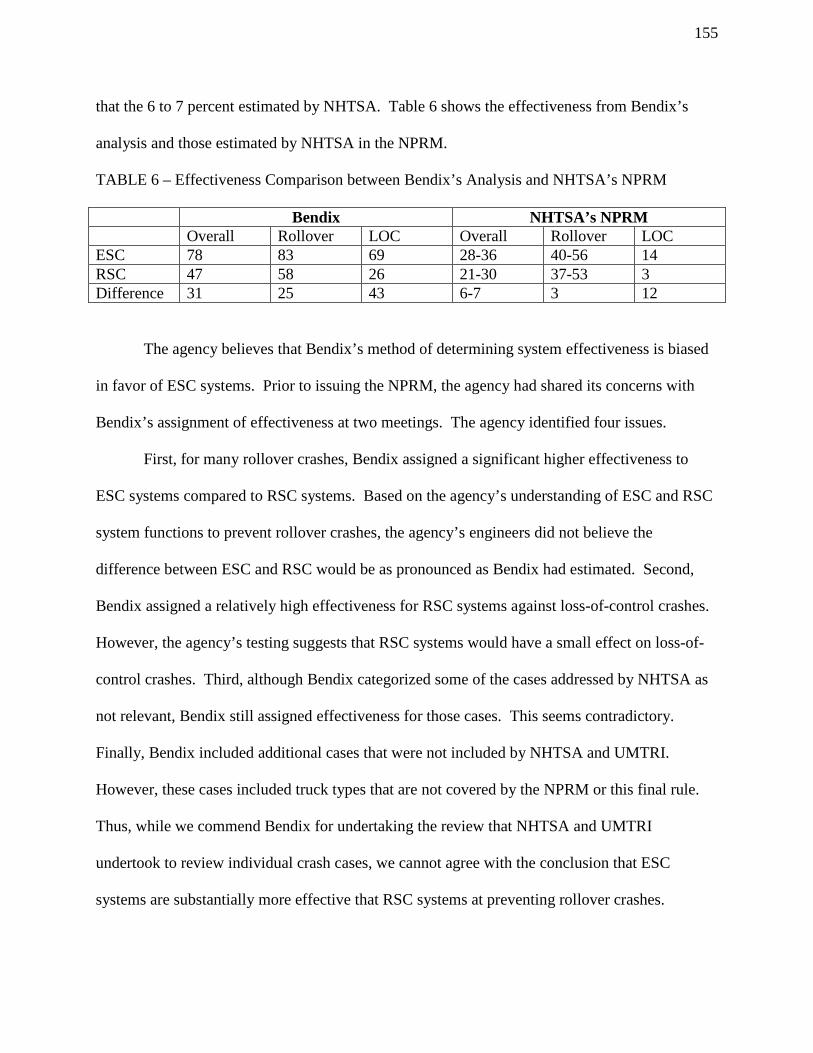
155
that the 6 to 7 percent estimated by NHTSA. Table 6 shows the effectiveness from Bendix’s
analysis and those estimated by NHTSA in the NPRM.
TABLE 6 – Effectiveness Comparison between Bendix’s Analysis and NHTSA’s NPRM
Bendix NHTSA’s NPRM Overall Rollover LOC Overall Rollover LOC ESC 78 83 69 28-36 40-56 14 RSC 47 58 26 21-30 37-53 3 Difference 31 25 43 6-7 3 12
The agency believes that Bendix’s method of determining system effectiveness is biased
in favor of ESC systems. Prior to issuing the NPRM, the agency had shared its concerns with
Bendix’s assignment of effectiveness at two meetings. The agency identified four issues.
First, for many rollover crashes, Bendix assigned a significant higher effectiveness to
ESC systems compared to RSC systems. Based on the agency’s understanding of ESC and RSC
system functions to prevent rollover crashes, the agency’s engineers did not believe the
difference between ESC and RSC would be as pronounced as Bendix had estimated. Second,
Bendix assigned a relatively high effectiveness for RSC systems against loss-of-control crashes.
However, the agency’s testing suggests that RSC systems would have a small effect on loss-of-
control crashes. Third, although Bendix categorized some of the cases addressed by NHTSA as
not relevant, Bendix still assigned effectiveness for those cases. This seems contradictory.
Finally, Bendix included additional cases that were not included by NHTSA and UMTRI.
However, these cases included truck types that are not covered by the NPRM or this final rule.
Thus, while we commend Bendix for undertaking the review that NHTSA and UMTRI
undertook to review individual crash cases, we cannot agree with the conclusion that ESC
systems are substantially more effective that RSC systems at preventing rollover crashes.

156
3. Effectiveness Estimate
In this final rule, we are generally using the effectiveness estimate used the NPRM,
which was derived from 2011 research note. However, we have made two modifications. First,
we have included an additional loss-of-control crash type (non-collision single-vehicle jackknife
crashes) that should have been included in the PRIA. Second, because we added an additional
loss-of-control crash type, we have reweighted the ratio of rollover to loss-of-control crashes.
However, these modifications have not substantially changed the effectiveness rates for ESC and
RSC systems from the rates presented in the NPRM. As shown in Table 7, ESC systems are
considered to be 3 percent more effective than RSC systems at reducing rollover crashes and 12
percent more effective at reducing loss-of-control crashes.
TABLE 7 -- Effectiveness Rates for ESC and RSC by Target Crash Types Technology Overall Rollover LOC ESC 25 – 32 40 – 56 14 RSC 17 – 24 37 – 53 2
Although the J-turn performance test does not measure an ESC system’s ability to
prevent loss-of-control crashes resulting from yaw instability, the equipment requirement ensures
some level of yaw stability performance. Our assessment for yaw stability control
performance is based on the ability of current generation ESC systems to prevent yaw instability,
just as our assessment for roll stability performance (which does have an associated performance
test) is based on the ability of current generation ESC systems to prevent roll instability.
C. Benefits Estimates
1. Safety Benefits
The crash benefits of this final rule were derived by multiplying the projected target
population, including fatalities, injuries, and property damage only crashes by the effectiveness

157
rate for both rollover and loss-of-control crashes. The benefits estimate for rollover crashes are
presented as a range because the ESC effectiveness rate is a range. In contrast, there is only one
estimate of benefits for loss-of-control crashes. Table 8 presents the benefits of this final rule.
As shown in that table, this final rule will prevent 1,424 to 1,759 crashes, 40 to 49 fatalities, and
505 to 649 injuries.
TABLE 8 -- Benefits of the Final rule
Crash Type Crashes Fatalities Injuries PDO Rollover 870 – 1,205 23 – 32 372 – 516 476 – 661 LOC 554 17 133 473 Total 1,424 – 1,759 40 – 49 505 – 649 949 – 1,134
2. Monetized Benefits
ESC systems are crash avoidance systems. Preventing a crash not only saves lives and
reduces injuries, but it also provides tangible benefits associated with the reduction in crashes.
These benefits include savings from medical care, emergency services, insurance administration,
workplace costs, legal costs, congestion, property damage, and productivity. We have broken
down these benefits into those that are injury related and those that are non-injury related. Of the
listed benefits, congestion and property damage reduction are non-injury-related benefits, and the
others are injury-related benefits. These benefits are estimated based upon periodic
examinations of the economic impact of vehicle crashes. The most recent analysis was
completed in 2014. 67
We have also monetized benefits in terms of the value of a statistical life (VSL), which
represents individuals’ willingness to pay to reduce the risk of dying. These benefits include the
67 Blincoe, L. J., Miller, T. R., Zaloshnja, E., & Lawrence, B. A., The economic and societal impact of motor vehicle crashes, 2010, (May 2014) (DOT HS 812 013).

158
value of quality of life, household productivity, and after-tax wages. These benefits are realized
through the life of the vehicle and must be discounted to reflect their value at the time of
purchase.
June 2014 guidance from the Department’s Office of the Secretary sets forth guidance for
the treatment of VSL in regulatory analysis. 68 This guidance establishes a VSL of $9.2 million
for analyses based on 2013 economics and a 1.18 percent annual adjustment rate for the VSL for
the next 30 years. The VSL is adjusted to reflect real increases in VSL that are likely to occur in
the future as consumers become economically better off in real terms over time.
Using this guidance applied to the prevention of crashes resulting in fatalities, injuries,
and property damage only, the following undiscounted monetized benefits of this final rule are
estimated.
TABLE 9 -- Undiscounted Monetized Benefits of the Final Rule (2013 Dollars)
Low High Societal Economic Savings for Crashworthiness $27,013,989 $34,526,917 Congestion and Property Damage $14,234,540 $17,566,251 Societal Economic Savings Total $41,248,529 $52,093,168 VSL $484,836,271 $603,762,776 Total Monetized Savings $526,084,800 $655,855,944
D. Cost Estimate
In the NPRM, we relied upon data received from manufacturers to estimate the costs of
implementing the proposal to require ESC systems on truck tractors and large buses. Based upon
these submissions, NHTSA calculated that the average cost of an ESC system for both truck
68 2014 Office of the Secretary memorandum on the "Guidance on Treatment of the Economic Value of a Statistical Life in U.S. Department of Transportation Analyses – 2014 Adjustment., June 13, 2014" http://www.dot.gov/regulations/economic-values-used-in-analysis

159
tractors and buses was $1,160 and the average cost of an RSC system was $640. Based on our
estimates that 150,000 truck tractors and 2,200 buses would be covered by the proposal, and the
estimates of 2012 ESC and RSC system adoption in the fleet, we estimated that the total cost of
the proposal would be $113.6 million in 2010 economics. Furthermore, we estimated that the
proposed SIS and SWD test maneuvers would cost approximately $15,000 per test to run,
assuming availability of test facilities, tracks, and vehicles.
We received specific a comment on the costs of ESC system from Bendix. Bendix stated
that they did not see a correlation between the cost differential estimated in the PRIA and those
from Bendix to its OEM customers. Bendix did not specify their cost differential. However,
Bendix stated that when ESC was mandated, they believed the cost would be in the lower end of
estimates. Thus, the net benefits of ESC would be further increased.
After publishing the NPRM, the agency published a cost teardown study for ESC and
RSC systems for heavy trucks to assess the required components and their unit costs. The results
were published in a report titled, “Cost and Weight Analysis of Electronic Stability Control and
Roll Stability Control for Heavy Trucks,” on October 25, 2012.69 The study looked at the
incremental costs of equipping vehicles with ESC and RSC systems over a baseline of ABS by
looking at one truck equipped only with ABS, two truck tractors equipped with RSC, one truck
tractor equipped with ESC, and one large bus equipped with ESC. The following table shows
the components and the cost of each component on the five vehicles that were examined.
69 See Docket No. NHTSA-2011-0066-0034.

160
TABLE 10 -- Component Cost Estimates for Baseline ABS and Four Stability Technology Systems in 2013 Dollars70
ABS WABCO Tractor Baseline
RSC Bendix Tractor
RSC WABCO Tractor
ESC Bendix Large Bus
ESC WABCO Tractor
component Total component Total component total component total component total Wheel Speed Sensor $11.85 $47.40 X X X X X X X X Wheel Speed Cables $5.32 $21.28 X X X X X X X X Dual Modulator Valves
$284.82 $569.64 X X X X X X X X
Modulator Valve Cables
$10.50 $42.00 X X X X X X X X
ECU $90.05 $90.05 X X X X X X X X Delta ECU* $37.80 $37.80 $50.36 $50.36 $37.80 $37.80 $43.58 $43.58 Solenoid Valves $29.20 $58.40 $29.20 $58.40 $29.20 $58.40 $29.20 $87.60 Solenoid Valve Cables
$9.58 $19.16 $9.58 $19.16 $9.58 $19.16 $9.58 $28.74
Lateral Accelerometer
$49.74 $49.74 In ECU In Yaw Sensor
In ESC Module
Modulator Valve (for trailer)**
$197.82 $197.82 $197.82 $197.82 $197.82 $197.82
Modulator Valve Cables (for trailer)
$10.50 $10.50 $10.50 $10.50 $10.50 $10.50
Yaw Rate Sensor $51.38 $51.38 In ESC Module
Pressure Sensor $2.14 $6.42 $2.14 $6.42 Pressure Sensor Cable
$10.12 $30.36 $10.12 $30.36
Steering Angle Sensor
$29.50 $29.50 $29.50 $29.50
ESC Module $85.48 $85.48 ESC Module Cable $28.86 $28.86 Baseline ABS Cost $770.37 Incremental Costs Above Baseline ABS
$373.42 $336.24 $233.02 $548.86
*Delta ECU is an incremental cost estimate over the cost of WABCO Tractor Baseline ABS ECU. ** Modulator Valve for trailer is added as a component in Bendix Tractor RSC, Meritor-WABCO Tractor RSC and Meritor-WABCO Tractor ESC since it is required to be installed in trailers in the final rule.
Furthermore, the installation of an ESC system requires a technician to tune a system for
each vehicle. We estimate that it will take one hour of labor to perform this task at the cost of
$33.40. Additionally, this final rule requires the installation of a telltale lamp using specific
symbols or text. We estimate the cost of this lamp and associated wiring at $2.96. Thus, we
estimate the total cost for installing an ESC system to be $585.22 on truck tractors and $269.38
on large buses. We have averaged the two estimates of the cost to install an RSC system, which
70 The cost teardown study is in 2011 economics, and it was revised to 2013 economics using an implicit price deflator (1.033=106.588/103.199).

161
is $391.19.71 We note that this estimate generally corresponds to the lower end of the cost
estimate in the FRIA, which is consistent with Bendix’s comment.
TABLE 11 – Summary of ESC and RSC System Unit Cost Estimates in 2013 Dollars ESC $585.22 RSC $391.19
ESC Incremental over RSC $194.03
We have also examined the effect of increased costs on vehicle sales. We expect that the
cost of ESC systems is relatively small compared to the estimated average cost of a truck tractor
of $110,000. We expect that this cost will be passed on to purchasers of truck tractors and large
buses. Those purchasers have indicated that truck operating costs represent about 21 percent of
total operating costs, and that the elasticity of demand for truck freight is approximately -1.174.
Thus, we believe that the increased costs of truck tractors related to this final rule will reduce
truck tractor sales by 101 units per year. We expect that this rule will have even less of an
impact on the sales of large buses, because the average cost of a bus affected by this rule is
approximately $400,000.
Based on our assumptions regarding costs and the estimates of ESC and RSC system
penetration in the market in 2018, we expect that this final rule will result in a total cost of $45.6
million. The costs are set forth in Tables 12 and 13. This total cost is based upon 21.3 percent of
truck tractors sold annually upgrading from RSC systems to ESC systems, 44.8 percent of truck
tractors sold annually without stability control systems installing ESC systems, and 20.0 percent
of large buses sold annually without stability control systems installing ESC systems.
Table 12 -- Total Cost of the Final rule (2013 $)
71 Unlike in the NPRM, the cost of installing an ESC system on a bus is considered to be substantially less than on a truck tractor. This is because an ESC system on a bus is not required to control a trailer’s brakes.

162
Technology Upgrade Needed Truck Tractors None Upgrade RSC to ESC ESC % Needing Improvements 33.9% 21.3% 44.8% 150,000 Sales Estimated 50,850 31,950 67,200 Costs per Affected Vehicle 0 $194.03 $585.22
Total Costs 0 $6.2 M $39.3 M Large Buses
% Needing Improvements 80% 0% 20% 2,200 Sales Estimated 1,760 0 440 Costs per Affected Vehicle 0 NA $269.38
Total Costs 0 $0 M $0.1 M M: million
Table 13 -- Summary of Vehicle Costs (2013 $)
Average Vehicle Costs Total Costs Truck Tractors $303.50 $45.5 M Large Buses $53.90 $0.1 M Total $299.90 $45.6 M
The agency estimates that the cost of executing the J-turn test maneuvers will be $13,400
per truck tractor and $20,100 per large bus, assuming access is available to test facilities, tracks,
and vehicles. The costs include preparation, brake burnish test, and other miscellaneous
preparations and required equipment. Table 14 presents these estimated costs. In addition, for
comparison purpose, the table also includes the costs for SWD maneuver that was proposed in
the NPRM. 72
Table 14 -- Estimated Compliance Test Cost per Vehicle (2013 $)
Cost Items J-Turn SWD Tractor Large Bus Tractor Large Bus
(1) Preparing for and executing the test maneuvers, $8,400.00 $12,800.00 $10,800.00 $14,700.00
72 We have revised the estimated SWD maneuver costs from the PRIA. In the PRIA, the estimated cost for SWD is $15,000 which included $10,000 for preparing for and executing the maneuvers, $2,000 for executing FMVSS No. 121 brake burnish test, and $3,000 for other miscellaneous preparations and required equipment.

163
(2) Executing brake burnish test, and $2,600.00 $3,600.00 $2,600.00 $3,600.00
(3) Other miscellaneous preparations and required equipment such as
$2,400.00 $3,700.00 $3,400.00 $4,800.00
(a) Brake conditioning between maneuvers, (b) Jackknife cable maintenance, (c) ballast loading, and (d) Post data processing, i.e., LAR and Torque reduction process. Sum $13,400.00 $20,100.00 $16,800.00 $23,100.00
E. Cost Effectiveness
Safety benefits can occur at any time during the vehicle’s lifetime. Therefore, the
benefits are discounted at both 3 and 7 percent to reflect their values in 2013 dollars, as reflected
in Table 15. Table 15 also shows that the net cost per equivalent life saved from this final rule
range from $0.1 to $0.3 million at a 3 percent discount rate and from $0.3 to $0.6 million at a 7
percent discount rate. The net benefits of this final rule are estimated to range from $412 to $525
million at a 3 percent discount rate and from $312 to $401 million at a 7 percent discount rate.
TABLE 15—Summary of Cost-Effectiveness and Net Benefits by Discount Rate (2013 $)
3% Discount 7% Discount Low High Low High Fatal Equivalents 40 50 32 40 Societal Economic Savings for Crashworthiness
$21,816,498 $27,883,938 $17,288,953 $22,097,227
Congestion and property Damage $11,495,815 $14,186,504 $9,110,106 $11,242,401
Total Societal Economic Savings (1) $33,312,313 $42,070,442 $26,399,059 $33,339,628 VSL $424,352,045 $528,442,215 $331,681,943 $413,040,877 Total Monetized Savings (2) $457,664,358 $570,512,657 $358,081,002 $446,380,505 Vehicle Costs* $45,644,570 $45,644,570 $45,644,570 $45,644,570

164
Net Costs (3) $12,332,257 $3,574,128 $19,245,511 $12,304,942 Net Cost Per Fatal Equivalent (4) $308,306 $71,483 $601,422 $307,624 Net Benefits (5) $412,019,788 $524,868,087 $312,436,432 $400,735,935 * Vehicle costs are not discounted, since they occur when the vehicle is purchased, whereas benefits occur over the vehicle’s lifetime and are discounted back to the time of purchase. (1) = Societal Economic Savings for Crashworthiness + VSL Savings (2) = Societal Economic Savings + VSL (3) = Vehicle Costs –Total Societal Economic Savings (4) = Net Costs/Fatal Equivalents (5) = VSL – Net Costs
F. Comparison of Regulatory Alternatives
The agency considered two alternatives to today’s final rule. The first alternative was
requiring RSC systems be installed on all newly manufactured truck tractors and buses covered
by this final rule. The second alternative was requiring RSC systems be installed on all newly
manufactured trailers.
Regarding the first alternative, requiring RSC systems be installed on truck tractors and
large buses, our research has concluded that RSC systems are less effective than ESC systems.
An RSC system is only slightly less effective at preventing rollover crashes than an ESC system,
but it is much less effective at preventing loss-of-control crashes. However, RSC systems are
estimated to cost less than ESC systems. Furthermore, only approximately 44.8% of truck
tractors will be required to install RSC systems based on data regarding manufacturers’ plans and
the agency’s estimates of ESC and RSC system adoption rates between 2012 and 2018.
A summary of the cost effectiveness of RSC systems is set forth in Table 16. When
comparing this alternative to today’s final rule, requiring RSC systems rather than ESC systems
would be slightly more cost effective. However, this alternative would save fewer lives and have
lower net benefits than this final rule. Consequently, the agency has rejected this alternative.

165
TABLE 16—Summary of Cost-Effectiveness and Net Benefits by Discount Rate Alternative 1–Requiring tractor-based RSC systems
(2013 $) 3% Discount 7% Discount Low High Low High Fatal Equivalents 25 35 20 28 Societal Economic Savings - Crashworthiness $14,708,167 $20,700,276 $11,655,804 $16,404,380
Congestion and property Damage $6,694,636 $9,378,093 $5,305,308 $7,431,871
Total Societal Economic Savings (1) $21,402,803 $30,078,369 $16,961,112 $23,836,251 VSL $260,249,473 $363,828,274 $203,416,130 $284,375,367 Total Monetized Savings (2) $281,652,276 $393,906,643 $220,377,242 $308,211,618 Vehicle Costs* $26,406,495 $26,406,495 $26,406,495 $26,406,495 Net Costs (3) $5,003,692 -$3,671,874 $9,445,383 $2,570,244 Net Cost Per Fatal Equivalent (4) $200,148 N/A $472,269 $91,794 Net Benefits (5) $255,245,781 $367,500,148 $193,970,747 $281,805,123 * Vehicle costs are not discounted, since they occur when the vehicle is purchased, whereas benefits occur over the vehicle’s lifetime and are discounted back to the time of purchase. (1) = Societal Economic Savings – Crashworthiness + VSL Savings (2) = Societal Economic Savings + VSL (3) = Vehicle Costs – Total Societal Economic Savings; Cost per equivalent life saved is not presented where the alternative results in negative net cost because there would be no cost per equivalent life saved. (4) = Net Costs/Fatal Equivalents (5) = VSL – Net Costs
The second alternative considered was requiring trailer-based RSC systems to be
installed on all newly manufactured trailers. Trailer-based RSC systems are only expected to
prevent rollover crashes. Based on 2006-2012 GES data, 98 percent of the target truck-tractor
crashes involve truck tractors with trailers attached. Therefore, the base crash population is 98
percent of Base 1 discussed above.

166
As discussed in the NPRM, it became apparent during testing that trailer-based stability
control systems were less effective than tractor-based systems because trailer-based systems
could only control the trailer’s brakes. Based upon the agency’s testing of trailer-based RSC
systems using a 150-foot J-turn test maneuver, the benefits of trailer-based RSC systems in
preventing rollover are about 17.6 percent of tractor-based ESC systems, corresponding to an
effectiveness rate of 7 to 10 percent.
The agency estimates that about 217,000 new trailers are manufactured each year.
Further, based on information from manufacturers, the agency estimates that a trailer-based RSC
system costs $400 per trailer. Available data indicates that as much as 5 percent of the current
annual production of trailers comes with RSC systems installed. Assuming all new trailers
would be required to install RSC, the cost of this alternative is estimated to be $74.7 million.
Table 17 sets forth a summary of the cost effectiveness of trailer-based RSC systems.
Because the operational life of a trailer (approximately 45 years) is much longer than that of a
truck tractor, it would take longer for trailer-based RSC systems to fully penetrate the fleet than
it would for any tractor-based system. Therefore, when the benefits of trailer-based RSC
systems are discounted at a 3 and 7 percent rate, there is a much higher discount factor. As can
be seen in Table 17, this results in this alternative having negative net benefits and a high cost
per life saved. Also, this alternative would have no effect on buses. Accordingly, the agency has
rejected this alternative.
TABLE 17—Summary of Cost-Effectiveness and Net Benefits by Discount Rate Alternative 2—Requiring trailer-based RSC systems
(2013 $) 3% Discount 7% Discount Low High Low High Fatal Equivalents 3 3 2 2 Societal Economic $1,571,042 $2,036,588 $1,057,467 $1,370,825

167
Savings - Crashworthiness Congestion and property Damage $684,213 $938,236 $460,543 $631,526 Total Societal Economic Savings (1) $2,255,255 $2,974,824 $1,518,010 $2,002,351 VSL $30,196,954 $39,659,995 $19,696,851 $25,869,398 Total Monetized Savings (2) $32,452,209 $42,634,819 $21,214,861 $27,871,749 Vehicle Costs* $74,734,800 $74,734,800 $74,734,800 $74,734,800 Net Costs (3) $72,479,545 $71,759,976 $73,216,790 $72,732,449 Net Cost Per Fatal Equivalent (4) $24,159,848 $23,919,992 $36,608,395 $36,366,225 Net Benefits (5) -$42,282,591 -$32,099,981 -$53,519,939 -$46,863,051 * Vehicle costs are not discounted, since they occur when the vehicle is purchased, whereas benefits occur over the vehicle’s lifetime and are discounted back to the time of purchase. (1) = Societal Economic Savings – Crashworthiness + VSL Savings (2) = Societal Economic Savings + VSL (3) = Vehicle Costs – Total Societal Economic Savings; negative means benefits are greater than the cost. (4) = Net Costs/Fatal Equivalents (5) = VSL – Net Costs
XV. Regulatory Analyses and Notices
A. Executive Order 12866, Executive Order 13563, and DOT Regulatory Policies and
Procedures
NHTSA has considered the impact of this rulemaking action under Executive Order
12866, Executive Order 13563, and the Department of Transportation's regulatory policies and
procedures. This rulemaking is considered economically significant and was reviewed by the
Office of Management and Budget under E.O. 12866, “Regulatory Planning and Review.” The
rulemaking action has also been determined to be significant under the Department’s regulatory
policies and procedures. NHTSA has placed in the docket a Final Regulatory Impact Analysis
(FRIA) describing the benefits and costs of this rulemaking action. The benefits and costs are
summarized in section XIV of this preamble.

168
Consistent with Executive Order 13563 and to the extent permitted under the Vehicle
Safety Act, we have considered the cumulative effects of the new regulations stemming from
NHTSA’s 2007 “NHTSA’s Approach to Motorcoach Safety” plan, DOT’s 2009 Motorcoach
Safety Action Plan, and the Motorcoach Enhanced Safety Act, and have taken steps to identify
opportunities to harmonize and streamline those regulations. By coordinating the timing and
content of the rulemakings, our goal is to expeditiously maximize the net benefits of the
regulations (by either increasing benefits or reducing costs or a combination of the two) while
simplifying requirements on the public and ensuring that the requirements are justified. We seek
to ensure that this coordination will also simplify the implementation of multiple requirements
on a single industry.
NHTSA’s Motorcoach Safety Action Plan identified four priority areas--passenger
ejection, rollover structural integrity, emergency egress, and fire safety. There have been other
initiatives on large bus performance, such as ESC systems—an action included in the DOT
plan—and an initiative to update the large bus tire standard.73 In deciding how best to initiate
and coordinate rulemaking in these areas, NHTSA examined various factors including the
benefits that would be achieved by the rulemakings, the anticipated vehicle designs and
countermeasures needed to comply with the regulations, and the extent to which the timing and
content of the rulemakings could be coordinated to lessen the need for multiple redesign and to
lower overall costs. After this examination, we decided on a course of action that prioritized the
goal of reducing passenger ejection and increasing frontal impact protection because many
benefits could be achieved expeditiously with countermeasures that were readily available (using
bus seats with integral seat belts, which are already available from seat suppliers) and whose
73 75 FR 60037 (Sept. 29, 2010).

169
installation would not significantly impact other vehicle designs. Similarly, we have also
determined that an ESC rulemaking presents relatively few synchronization issues with other
rules, because the vehicles at issue already have the foundation braking systems needed for the
stability control technology and the additional equipment necessary for an ESC system are
sensors that are already available and that can be installed without significant effect on other
vehicle systems. Further, we estimate that 80 percent of the affected buses already have ESC
systems. We realize that a rollover structural integrity rulemaking, or an emergency egress
rulemaking, could involve more redesign of vehicle structure than rules involving systems such
as seat belts, ESC, or tires.74 Our decision-making in these and all the rulemakings outlined in
the “NHTSA’s Approach to Motorcoach Safety” plan, DOT’s Motorcoach Safety Action Plan,
and the Motorcoach Enhanced Safety Act will be cognizant of the timing and content of the
actions so as to simplify requirements applicable to the public and private sectors, ensure that
requirements are justified, and increase the net benefits of the resulting safety standards.
B. Regulatory Flexibility Act
Pursuant to the Regulatory Flexibility Act (5 U.S.C. 601 et seq., as amended by the Small
Business Regulatory Enforcement Fairness Act (SBREFA) of 1996), whenever an agency is
required to publish a notice of rulemaking for any proposed or final rule, it must prepare and
make available for public comment a regulatory flexibility analysis that describes the effect of
the rule on small entities (i.e., small businesses, small organizations, and small governmental
jurisdictions). The Small Business Administration's regulations at 13 CFR Part 121 define a
small business, in part, as a business entity "which operates primarily within the United States."
74 The initiative on fire safety is in a research phase. Rulemaking resulting from the research will not occur in the near term.

170
(13 CFR 121.105(a)). No regulatory flexibility analysis is required if the head of an agency
certifies the rule will not have a significant economic impact on a substantial number of small
entities. SBREFA amended the Regulatory Flexibility Act to require Federal agencies to provide
a statement of the factual basis for certifying that a rule will not have a significant economic
impact on a substantial number of small entities.
NHTSA has considered the effects of this final rule under the Regulatory Flexibility Act.
I certify that this final rule will not have a significant economic impact on a substantial number
of small entities. This final rule will directly impact manufacturers of truck-tractors, large buses,
and stability control systems for those vehicles. It will indirectly affect purchasers of new truck-
tractors and large buses, which include both fleets and owner-operators. NHTSA believes the
entities directly affected by this rule do not qualify as small entities. Inasmuch as some second-
stage manufacturers of certain body-on-frame buses that are subject to this final rule are small
businesses, this final rule will not substantially affect those small businesses. The small
manufacturers that may be affected by this rule are final stage manufacturers that purchase
incomplete vehicles from other large manufacturers and complete the manufacturing process.
The incomplete vehicle manufacturers, which we do not believe are small businesses, typically
certify compliance with all braking-related standards and we believe ESC would be included
among those. The sole effect on the final stage manufacturers is a marginal increase in the cost
of incomplete vehicles due to the addition of ESC systems. This additional cost is very small
relative to the average cost of buses subject to this final rule ($200,000 to $500,000), and the
costs would likely ultimately be passed on to the final purchaser.

171
C. Executive Order 13132 (Federalism)
NHTSA has examined today’s final rule pursuant to Executive Order 13132 (64 FR
43255, August 10, 1999) and concluded that no additional consultation with States, local
governments or their representatives is mandated beyond the rulemaking process. The agency
has concluded that the rulemaking will not have sufficient federalism implications to warrant
consultation with State and local officials or the preparation of a federalism summary impact
statement. The final rule will not have “substantial direct effects on the States, on the
relationship between the national government and the States, or on the distribution of power and
responsibilities among the various levels of government.”
NHTSA rules can preempt in two ways. First, the National Traffic and Motor Vehicle
Safety Act contains an express preemption provision: When a motor vehicle safety standard is in
effect under this chapter, a State or a political subdivision of a State may prescribe or continue in
effect a standard applicable to the same aspect of performance of a motor vehicle or motor
vehicle equipment only if the standard is identical to the standard prescribed under this
chapter. 49 U.S.C. § 30103(b)(1). It is this statutory command by Congress that preempts any
non-identical State legislative and administrative law addressing the same aspect of performance.
The express preemption provision described above is subject to a savings clause under
which “[c]ompliance with a motor vehicle safety standard prescribed under this chapter does not
exempt a person from liability at common law.” 49 U.S.C. § 30103(e). Pursuant to this
provision, State common law tort causes of action against motor vehicle manufacturers that
might otherwise be preempted by the express preemption provision are generally
preserved. However, the Supreme Court has recognized the possibility, in some instances, of
implied preemption of such State common law tort causes of action by virtue of NHTSA’s rules,

172
even if not expressly preempted. This second way that NHTSA rules can preempt is dependent
upon there being an actual conflict between an FMVSS and the higher standard that would
effectively be imposed on motor vehicle manufacturers if someone obtained a State common law
tort judgment against the manufacturer, notwithstanding the manufacturer’s compliance with the
NHTSA standard. Because most NHTSA standards established by an FMVSS are minimum
standards, a State common law tort cause of action that seeks to impose a higher standard on
motor vehicle manufacturers will generally not be preempted. However, if and when such a
conflict does exist - for example, when the standard at issue is both a minimum and a maximum
standard - the State common law tort cause of action is impliedly preempted. See Geier v.
American Honda Motor Co., 529 U.S. 861 (2000).
Pursuant to Executive Order 13132 and 12988, NHTSA has considered whether this rule
could or should preempt State common law causes of action. The agency’s ability to announce
its conclusion regarding the preemptive effect of one of its rules reduces the likelihood that
preemption will be an issue in any subsequent tort litigation.
To this end, the agency has examined the nature (e.g., the language and structure of the
regulatory text) and objectives of today’s rule and finds that this rule, like many NHTSA rules,
prescribes only a minimum safety standard. As such, NHTSA does not intend that this rule
preempt state tort law that would effectively impose a higher standard on motor vehicle
manufacturers than that established by today’s rule. Establishment of a higher standard by
means of State tort law would not conflict with the minimum standard announced here. Without
any conflict, there could not be any implied preemption of a State common law tort cause of
action.

173
D. Executive Order 12988 (Civil Justice Reform)
With respect to the review of the promulgation of a new regulation, section 3(b) of
Executive Order 12988, “Civil Justice Reform” (61 FR 4729; Feb. 7, 1996), requires that
Executive agencies make every reasonable effort to ensure that the regulation: (1) clearly
specifies the preemptive effect; (2) clearly specifies the effect on existing Federal law or
regulation; (3) provides a clear legal standard for affected conduct, while promoting
simplification and burden reduction; (4) clearly specifies the retroactive effect, if any; (5)
specifies whether administrative proceedings are to be required before parties file suit in court;
(6) adequately defines key terms; and (7) addresses other important issues affecting clarity and
general draftsmanship under any guidelines issued by the Attorney General. This document is
consistent with that requirement.
Pursuant to this Order, NHTSA notes as follows. The issue of preemption is discussed
above. NHTSA notes further that there is no requirement that individuals submit a petition for
reconsideration or pursue other administrative proceedings before they may file suit in court.
E. Protection of Children from Environmental Health and Safety Risks
Executive Order 13045, “Protection of Children from Environmental Health and Safety
Risks” (62 FR 19855, April 23, 1997), applies to any rule that: (1) is determined to be
“economically significant” as defined under Executive Order 12866, and (2) concerns an
environmental, health, or safety risk that the agency has reason to believe may have a
disproportionate effect on children. If the regulatory action meets both criteria, the agency must
evaluate the environmental health or safety effects of the planned rule on children, and explain
why the planned regulation is preferable to other potentially effective and reasonably feasible
alternatives considered by the agency.

174
This notice is part of a rulemaking that is not expected to have a disproportionate health
or safety impact on children. Consequently, no further analysis is required under Executive
Order 13045.
F. Paperwork Reduction Act
Under the Paperwork Reduction Act of 1995 (PRA), a person is not required to respond
to a collection of information by a Federal agency unless the collection displays a valid OMB
control number. There is not any information collection requirement associated with this final
rule.
G. National Technology Transfer and Advancement Act
Section 12(d) of the National Technology Transfer and Advancement Act (NTTAA)
requires NHTSA to evaluate and use existing voluntary consensus standards in its regulatory
activities unless doing so would be inconsistent with applicable law (e.g., the statutory provisions
regarding NHTSA's vehicle safety authority) or otherwise impractical. Voluntary consensus
standards are technical standards developed or adopted by voluntary consensus standards bodies.
Technical standards are defined by the NTTAA as “performance-based or design-specific
technical specification and related management systems practices.” They pertain to “products
and processes, such as size, strength, or technical performance of a product, process or material.”
Examples of organizations generally regarded as voluntary consensus standards bodies
include ASTM International, SAE International (SAE), and the American National Standards
Institute (ANSI). If NHTSA does not use available and potentially applicable voluntary
consensus standards, we are required by the Act to provide Congress, through OMB, an
explanation of the reasons for not using such standards.

175
This final rule requires truck tractors and large buses to have electronic stability control
systems. In the definitional criteria, the agency adapted the criteria based on the light vehicle
ESC rulemaking, which was based on (with minor modifications) SAE Surface Vehicle
Information Report on Automotive Stability Enhancement Systems J2564 JUN2004 that
provides an industry consensus definition of an ESC system. In addition, SAE International has
a Recommended Practice on Brake Systems Definitions-Truck and Bus, J2627 AUG2009 that
has been incorporated into the agency’s definition.
The agency based the performance requirement (with modifications) on SAE Surface
Vehicle Recommended Practice J266 JAN96, Steady-State Directional Control Test Procedures
for Passenger Cars and Light Trucks. UN ECE Regulation 13 also allows the J-Turn test
maneuver as one option to be used for demonstrating proper function of an ESC system.
The agency has also incorporated by reference two ASTM standards in order to provide
specifications for the road test surface. These are: (1) ASTM E1136-93 (Reapproved 2003),
“Standard Specification for a Radial Standard Reference Test Tire,” and (2) ASTM E1337-90
(Reapproved 2008), “Standard Test Method for Determining Longitudinal Peak Braking
Coefficient of Paved Surfaces Using a Standard Reference Test Tire.”
H. Unfunded Mandates Reform Act
Section 202 of the Unfunded Mandates Reform Act of 1995 (UMRA) requires federal
agencies to prepare a written assessment of the costs, benefits, and other effects of proposed or
final rules that include a Federal mandate likely to result in the expenditure by State, local, or
tribal governments, in the aggregate, or by the private sector, of more than $100 million annually
(adjusted for inflation with base year of 1995). Before promulgating a rule for which a written
statement is needed, section 205 of the UMRA generally requires the agency to identify and

176
consider a reasonable number of regulatory alternatives and adopt the least costly, most cost-
effective, or least burdensome alternative that achieves the objectives of the rule. The provisions
of section 205 do not apply when they are inconsistent with applicable law. Moreover, section
205 allows the agency to adopt an alternative other than the least costly, most cost-effective, or
least burdensome alternative if the agency publishes with the final rule an explanation of why
that alternative was not adopted.
This final rule will not result in any expenditure by State, local, or tribal governments or
the private sector of more than $100 million, adjusted for inflation.
I. National Environmental Policy Act
NHTSA has analyzed this rulemaking action for the purposes of the National
Environmental Policy Act. The agency has determined that implementation of this action will
not have any significant impact on the quality of the human environment.
J. Incorporation by Reference
As discussed earlier in the relevant portions of this document, we are incorporating by
reference various materials into the Code of Federal Regulations in this rulemaking. The
standards we are incorporating are:
• ASTM E1136–93 (Reapproved 2003), “Standard Specification for a Radial Standard
Reference Test Tire,” approved March 15, 1993.
• ASTM E1337–90 (Reapproved 2008), “Standard Test Method for Determining
Longitudinal Peak Braking Coefficient of Paved Surfaces Using a Standard Reference
Test Tire,” approved June 1, 2008.

177
Under 5 U.S.C. § 552(a)(1)(E), Congress allows agencies to incorporate by reference
materials that are reasonably available to the class of persons affected if the agency has approval
from the Director of the Federal Register. As a part of that approval process, the Director of the
Federal Register (in 1 CFR § 51.5) directs agencies to discuss (in the preamble) the ways that the
materials we are incorporating by reference are reasonably available to interested parties.
Further the Director requires agencies to summarize the material that they are incorporating
[proposing to incorporate] by reference.
NHTSA has worked to ensure that standards being considered for incorporation by
reference are reasonably available to the class of persons affected. In this case, those directly
affected by incorporated provisions are NHTSA and parties contracting with NHTSA to conduct
testing of new vehicles. New vehicle manufacturers may also be affected to the extent they wish
to conduct NHTSA’s compliance test procedures on their own vehicles. These entities have
access to copies of aforementioned standards through ASTM International for a reasonable fee.
These entities have the financial capability to obtain a copy of the material incorporated by
reference.
Other interested parties in the rulemaking process beyond the class affected by the
regulation include members of the public, safety advocacy groups, etc. Such interested parties
can access the standard by obtaining a copy from the aforementioned standards development
organizations.
Interested parties may also access the standards through NHTSA or the National
Archives and Records Administration (NARA). All approved material is available for inspection
at NHTSA, 1200 New Jersey Avenue SE, Washington, DC 20590, and at the National Archives
and Records Administration (NARA). For information on the availability of this material at

178
NHTSA, contact NHTSA’s Office of Technical Information Services, phone number (202) 366-
2588. For information on the availability of this material at NARA, call (202) 741-6030, or go
to: http://www.archives.gov/federal-register/cfr/ibr-locations.html.
Finally, we have also described and summarized the materials that we are incorporating
by reference in this document to give all interested parties an effective opportunity to comment.
The materials were previously discussed in section XI.G.
K. Regulatory Identifier Number (RIN)
The Department of Transportation assigns a regulation identifier number (RIN) to each
regulatory action listed in the Unified Agenda of Federal Regulations. The Regulatory
Information Service Center publishes the Unified Agenda in April and October of each year.
You may use the RIN contained in the heading at the beginning of this document to find this
action in the Unified Agenda.
L. Privacy Act
Anyone is able to search the electronic form of all comments received into any of our
dockets by the name of the individual submitting the comment (or signing the comment, if
submitted on behalf of an association, business, labor union, etc.). You may review DOT's
complete Privacy Act Statement in the Federal Register published on April 11, 2000 (65 FR
19477-78).
List of Subjects in 49 CFR Part 571
Imports, Incorporation by reference, Motor vehicle safety, Motor vehicles, Rubber and
rubber products, and Tires.
Regulatory Text
In consideration of the foregoing, we amend 49 CFR part 571 to read as follows:

179
PART 571 – FEDERAL MOTOR VEHICLE SAFETY STANDARDS
1. The authority citation for Part 571 continues to read as follows:
Authority: 49 U.S.C. 322, 30111, 30115, 30166 and 30177; delegation of authority at 49 CFR
1.95.
2. Revise paragraphs (d)(33) and (d)(34) of § 571.5 to read as follows:
§ 571.5 Matter incorporated by reference
* * * * *
(d) * * *
(33) ASTM E1136–93 (Reapproved 2003), “Standard Specification for a Radial Standard
Reference Test Tire,” approved March 15, 1993, into §§ 571.105; 571.121; 571.122; 571.126;
571.135; 571.136; 571.139; 571.500.
(34) ASTM E1337–90 (Reapproved 2008), “Standard Test Method for Determining
Longitudinal Peak Braking Coefficient of Paved Surfaces Using a Standard Reference Test
Tire,” approved June 1, 2008, into §§ 571.105; 571.121; 571.122; 571.126; 571.135; 571.136;
571.500.
* * * * *
3. Revise Table 1 of § 571.101 to read as follows:
Table 1 Controls, Telltales, and Indicators
With Illumination or Color Requirements1
Column 1
ITEM Column 2 SYMBOL
Column 3 WORDS OR
ABBRE-VIATIONS
Column 4 FUNCTION
Column 5 ILLUMIN-
ATION
Column 6 COLOR
Highbeam 2
3, 5
------- Telltale ------- Blue or Green 4

180
Column 1 ITEM
Column 2 SYMBOL
Column 3 WORDS OR
ABBRE-VIATIONS
Column 4 FUNCTION
Column 5 ILLUMIN-
ATION
Column 6 COLOR
Turn signals 2
3, 6
------- Control ------- -------
Telltale ------- Green 4
Hazard warning signal
3
Hazard Control Yes -------
------- Telltale 7 ------- -------
Position, side marker, end-outline marker, identification, or clearance lamps
3,8
Marker Lamps or
MK Lps 8
Control Yes -------
Windshield wiping system
Wiper or
Wipe Control Yes -------
Windshield washing system
Washer or
Wash Control Yes -------
Windshield washing and wiping system combined
Washer-Wiper or
Wash-Wipe Control Yes -------
Windshield defrosting and defogging system
Defrost, Defog, or
Def. Control Yes -------
Rear window defrosting and defogging system
Rear Defrost, Rear Defog, Rear Def., or
R-Def.
Control Yes -------
Brake system malfunction ------- Brake Telltale ------- Red 4
Antilock brake system malfunction for vehicles subject to FMVSS 105 or 135
------- Antilock,
Anti-lock, or ABS 9
Telltale ------- Yellow
Malfunction in Variable Brake Proportioning System ------- Brake
Proportioning 9 Telltale ------- Yellow

181
Column 1 ITEM
Column 2 SYMBOL
Column 3 WORDS OR
ABBRE-VIATIONS
Column 4 FUNCTION
Column 5 ILLUMIN-
ATION
Column 6 COLOR
Regenerative brake system malfunction ------- RBS or
ABS/RBS 9 Telltale ------- Yellow
Malfunction in antilock system for vehicles other than trailers subject to FMVSS 121
------- ABS
or Antilock 9
Telltale ------- Yellow
Antilock brake system trailer fault for vehicles subject to FMVSS 121
Trailer ABS or
Trailer Antilock Telltale ------- Yellow
Brake pressure (for vehicles subject to FMVSS 105 or 135)
------- Brake Pressure 9
Telltale ------- Red 4
Low brake fluid condition (for vehicles subject to FMVSS 105 or 135)
------- Brake Fluid 9 Telltale ------- Red 4
Parking brake applied (for vehicles subject to FMVSS 105 or 135)
------- Park or
Parking Brake 9
Telltale ------- Red 4
Brake lining wear-out condition (for vehicles subject to FMVSS 135)
------- Brake Wear 9 Telltale ------- Red 4
Electronic Stability Control System Malfunction (for vehicles subject to FMVSS 126) 10, 11
ESC 12 Telltale ------- Yellow
Electronic Stability Control System “OFF” (for vehicles subject to FMVSS 126) 10
ESC OFF
Control Yes -------
Telltale ------- Yellow

182
Column 1 ITEM
Column 2 SYMBOL
Column 3 WORDS OR
ABBRE-VIATIONS
Column 4 FUNCTION
Column 5 ILLUMIN-
ATION
Column 6 COLOR
Electronic Stability Control System Malfunction (for vehicles subject to FMVSS 136) 11
or
or
ESC Telltale ------- Yellow
Fuel Level
or
Fuel Telltale ------- -------
Indicator Yes -------
Engine oil pressure
13
Oil Telltale ------- -------
Indicator Yes -------
Engine coolant temperature
13
Temp Telltale ------- -------
Indicator Yes -------
Electrical charge
Volts or Charge or
Amp
Telltale ------- -------
Indicator Yes -------
Engine stop ------- Engine Stop 14 Control Yes -------
Automatic vehicle speed (cruise control) ------- ------- Control Yes -------
Speedometer ------- MPH, or MPH
and km/h 15 Indicator Yes -------

183
Column 1 ITEM
Column 2 SYMBOL
Column 3 WORDS OR
ABBRE-VIATIONS
Column 4 FUNCTION
Column 5 ILLUMIN-
ATION
Column 6 COLOR
Heating and Air conditioning system ------- ------- Control Yes -------
Automatic (park) transmission (reverse) control (neutral) position (drive)
-------
16
Indicator Yes -------
Heating and/or air conditioning fan
or
Fan Control Yes -------
Low Tire Pressure (including malfunction) (See FMVSS 138) 17
Low Tire 17 Telltale ------- Yellow
Low Tire Pressure (including malfunction that identifies involved tire) (See FMVSS 138) 17
Low Tire 17 Telltale ------- Yellow
Tire Pressure Monitoring System Malfunction (See FMVSS 138) 18
------- TPMS 17, 19 Telltale ------- Yellow
Notes: 1 An identifier is shown in this table if it is required for a control for which an illumination requirement exists or if it is used for a telltale for which a color requirement exists. If a line appears in column 2 and column 3, the control, telltale, or indicator is required to be identified, however the form of the identification is the manufacturer’s option. Telltales are not considered to have an illumination requirement, because by definition the telltale must light when the condition for its activation exists. 2 Additional requirements in FMVSS 108. 3 Framed areas of the symbol may be solid; solid areas may be framed. 4 Blue may be blue-green. Red may be red-orange. 5 Symbols employing four lines instead of five may also be used. 6 The pair of arrows is a single symbol. When the controls or telltales for left and right turn operate independently, however, the two arrows may be considered separate symbols and be spaced accordingly. 7 Not required when arrows of turn signal telltales that otherwise operate independently flash simultaneously as hazard warning telltale. 8 Separate identification is not required if function is combined with master lighting switch. 9 Refer to FMVSS 105 or FMVSS 135, as appropriate, for additional specific requirements for brake telltale labeling and color. If a single telltale is used to indicate more than one brake system condition, the brake system malfunction identifier must be used. 10 Requirement effective September 1, 2011. 11 A manufacturer may use this telltale in flashing mode to indicate ESC operation.

184
12 This symbol may also be used to indicate the malfunction of related systems/functions, including traction control, trailer stability assist, corner brake control, and other similar functions that use throttle and/or individual wheel torque control to operate and share common components with ESC. 13 Combination of the engine oil pressure symbol and the engine coolant temperature symbol in a single telltale is permitted. 14 Use when engine control is separate from the key locking system. 15 If the speedometer is graduated in both miles per hour and in kilometers per hour, the scales must be identified “MPH” and “km/h”, respectively, in any combination of upper- and lowercase letters. 16 The letters ‘P’, ‘R’, ‘N’, and ‘D’ are considered separate identifiers for the individual gear positions. Their locations within the vehicle, and with respect to each other, are governed by FMVSS 102. The letter ‘D’ may be replaced by another alphanumeric character or symbol chosen by the manufacturer. 17 Required only for FMVSS 138 compliant vehicles. 18 Alternatively, either low tire pressure telltale may be used to indicate a TPMS malfunction. See FMVSS 138. 19 Required only for vehicles manufactured on or after September 1, 2007.
4. Revise the heading of § 571.126 to read as follows:
§ 571.126 Standard No. 126; Electronic stability control systems for light vehicles
* * * * *
5. Add § 571.136 to read as follows:
§ 571.136 Standard No. 136; Electronic stability control systems for heavy vehicles
S1 Scope. This standard establishes performance and equipment requirements for
electronic stability control (ESC) systems on heavy vehicles.
S2 Purpose. The purpose of this standard is to reduce crashes caused by rollover or by
directional loss-of-control.
S3 Application. This standard applies to the following vehicles:
S3.1 Truck tractors with a gross vehicle weight rating of greater than 11,793 kilograms
(26,000 pounds). However, it does not apply to:
(a) Any truck tractor equipped with an axle that has a gross axle weight rating of 13,154
kilograms (29,000 pounds) or more;
(b) Any truck tractor that has a speed attainable in 3.2 km (2 miles) of not more than 53
km/h (33 mph); and

185
(c) Any truck tractor that has a speed attainable in 3.2 km (2 miles) of not more than 72
km/h (45 mph), an unloaded vehicle weight that is not less than 95 percent of its gross vehicle
weight rating, and no capacity to carry occupants other than the driver and operating crew.
S3.2 Buses with a gross vehicle weight rating of greater than 11,793 kilograms (26,000
pounds). However, it does not apply to
(a) School buses;
(b) Perimeter-seating buses;
(c) Transit buses;
(d) Any bus equipped with an axle that has a gross axle weight rating of 13,154
kilograms (29,000 pounds) or more; and
(e) Any bus that has a speed attainable in 3.2 km (2 miles) of not more than 53 km/h (33
mph.)
S4 Definitions.
Ackerman Steer Angle means the angle whose tangent is the wheelbase divided by the
radius of the turn at a very low speed.
Electronic stability control system or ESC system means a system that has all of the
following attributes:
(1) It augments vehicle directional stability by having the means to apply and adjust the
vehicle brake torques individually at each wheel position on at least one front and at least one
rear axle of the truck tractor or bus to induce correcting yaw moment to limit vehicle oversteer
and to limit vehicle understeer;

186
(2) It enhances rollover stability by having the means to apply and adjust the vehicle
brake torques individually at each wheel position on at least one front and at least one rear axle
of the truck tractor or bus to reduce lateral acceleration of a vehicle;
(3) It is computer-controlled with the computer using a closed-loop algorithm to induce
correcting yaw moment and enhance rollover stability;
(4) It has a means to determine the vehicle’s lateral acceleration;
(5) It has a means to determine the vehicle’s yaw rate and to estimate its side slip or side
slip derivative with respect to time;
(6) It has a means to estimate vehicle mass or, if applicable, combination vehicle mass;
(7) It has a means to monitor driver steering inputs;
(8) It has a means to modify engine torque, as necessary, to assist the driver in
maintaining control of the vehicle and/or combination vehicle; and
(9) When installed on a truck tractor, it has the means to provide brake pressure to
automatically apply and modulate the brake torques of a towed trailer.
ESC service brake application means the time when the ESC system applies a service
brake pressure at any wheel for a continuous duration of at least 0.5 second of at least 34 kPa (5
psi) for air-braked systems and at least 172 kPa (25 psi) for hydraulic-braked systems.
Initial brake temperature means the average temperature of the service brakes on the
hottest axle of the vehicle immediately before any stability control system test maneuver is
executed.
Lateral acceleration means the component of the vector acceleration of a point in the
vehicle perpendicular to the vehicle x-axis (longitudinal) and parallel to the road plane.

187
Oversteer means a condition in which the vehicle’s yaw rate is greater than the yaw rate
that would occur at the vehicle’s speed as result of the Ackerman Steer Angle.
Over-the-road bus means a bus characterized by an elevated passenger deck located over
a baggage compartment, except a school bus.
Peak friction coefficient or PFC means the ratio of the maximum value of braking test
wheel longitudinal force to the simultaneous vertical force occurring prior to wheel lockup, as
the braking torque is progressively increased.
Perimeter-seating bus means a bus with 7 or fewer designated seating positions rearward
of the driver's seating position that are forward-facing or can convert to forward-facing without
the use of tools and is not an over-the-road bus.
Side slip or side slip angle means the arctangent of the lateral velocity of the center of
gravity of the vehicle divided by the longitudinal velocity of the center of gravity.
Snub means the braking deceleration of a vehicle from a higher speed to a lower speed
that is greater than zero.
Stop-request system means a vehicle-integrated system for passenger use to signal to a
vehicle operator that they are requesting a stop.
Transit bus means a bus that is equipped with a stop-request system sold for public
transportation provided by, or on behalf of, a State or local government and that is not an over-
the-road bus.
Understeer means a condition in which the vehicle’s yaw rate is less than the yaw rate
that would occur at the vehicle’s speed as result of the Ackerman Steer Angle.
Yaw Rate means the rate of change of the vehicle’s heading angle measure in degrees per
second of rotation about a vertical axis through the vehicle’s center of gravity.

188
S5 Requirements. Each vehicle must be equipped with an ESC system that meets the
requirements specified in S5 under the test conditions specified in S6 and the test procedures
specified in S7 of this standard.
S5.1 Required Equipment. Each vehicle to which this standard applies must be equipped
with an electronic stability control system, as defined in S4.
S5.2 System Operational Capabilities.
S5.2.1 The ESC system must be operational over the full speed range of the vehicle
except at vehicle speeds less than 20 km/h (12.4 mph), when being driven in reverse, or during
system initialization.
S5.2.2 The ESC must remain capable of activation even if the antilock brake system or
traction control is also activated.
S5.3 Performance Requirements.
S5.3.1 Lane Keeping During Reference Speed Determination. During each series of four
consecutive test runs conducted at the same entrance speed as part of the test procedure to
determine the Preliminary Reference Speed and the Reference Speed (see S7.7.1), the wheels of
the truck tractor or bus must remain within the lane between the start gate (0 degrees of radius
arc angle) and the end gate (120 degrees of radius arc angle) during at least two of the four test
runs.
S5.3.2 Engine Torque Reduction. During each series of four consecutive test runs for the
determination of engine torque reduction (see S7.7.2), the vehicle must satisfy the criteria of
S5.3.2.1 and S5.3.2.2 during at least two of the four test runs.
S5.3.2.1 The ESC system must reduce the driver-requested engine torque by at least 10
percent for a minimum continuous duration of 0.5 second during the time period from 1.5
189
seconds after the vehicle crosses the start gate (0 degree of radius arc angle) to when it crosses
the end gate (120 degrees of radius arc angle).
S5.3.2.2 The wheels of the truck tractor or bus must remain within the lane between the
start gate (0 degrees of radius arc angle) and the end gate (120 degrees of radius arc angle).
S5.3.3 Roll Stability Control Test. During each series of eight consecutive test runs for
the determination of roll stability control (see S7.7.3) conducted at the same entrance speed, the
vehicle must satisfy the criteria of S5.3.3.1, S5.3.3.2, S5.3.3.3, and S5.3.3.4 during at least six of
the eight consecutive test runs.
S5.3.3.1 The vehicle speed measured at 3.0 seconds after vehicle crosses the start gate (0
degrees of radius arc angle) must not exceed 47 km/h (29 mph).
S5.3.3.2 The vehicle speed measured at 4.0 seconds after vehicle crosses the start gate (0
degrees of radius arc angle) must not exceed 45 km/h (28 mph).
S5.3.3.3 The wheels of the truck tractor or bus must remain within the lane between the
start gate (0 degrees of radius arc angle) and the end gate (120 degrees of radius arc angle).
S5.3.3.4 There must be ESC service brake activation.
S5.4 ESC Malfunction Detection. Each vehicle must be equipped with an indicator lamp,
mounted in front of and in clear view of the driver, which is activated whenever there is a
malfunction that affects the generation or transmission of control or response signals in the
vehicle’s electronic stability control system.
S5.4.1 Except as provided in S5.4.3 and S5.4.6, the ESC malfunction telltale must
illuminate only when a malfunction exists and must remain continuously illuminated for as long
as the malfunction exists, whenever the ignition locking system is in the “On” (“Run”) position.

190
S5.4.2 The ESC malfunction telltale must be identified by the symbol shown for
“Electronic Stability Control System Malfunction” or the specified words or abbreviations listed
in Table 1 of Standard No. 101 (49 CFR 571.101).
S5.4.3 The ESC malfunction telltale must be activated as a check-of-lamp function either
when the ignition locking system is turned to the “On” (“Run”) position when the engine is not
running, or when the ignition locking system is in a position between the “On” (“Run”) and
“Start” that is designated by the manufacturer as a check-light position.
S5.4.4 The ESC malfunction telltale need not be activated when a starter interlock is in
operation.
S5.4.5 The ESC malfunction telltale lamp must extinguish at the next ignition cycle after
the malfunction has been corrected.
S5.4.6 The manufacturer may use the ESC malfunction telltale in a flashing mode to
indicate ESC operation.
S6 Test Conditions. The requirements of S5 must be met by a vehicle when it is tested
according to the conditions set forth in the S6, without replacing any brake system part or
making any adjustments to the ESC system except as specified. On vehicles equipped with
automatic brake adjusters, the automatic brake adjusters will remain activated at all times.
S6.1 Ambient Conditions.
S6.1.1 The ambient temperature is any temperature between 2 °C (35 °F) and 40 °C (104
°F).
S6.1.2 The maximum wind speed is no greater than 5 m/s (11 mph).
S6.2 Road Test Surface.

191
S6.2.1 The tests are conducted on a dry, uniform, solid-paved surface. Surfaces with
irregularities and undulations, such as dips and large cracks, are unsuitable.
S6.2.2 The road test surface produces a peak friction coefficient (PFC) of 0.9 when
measured using an American Society for Testing and Materials (ASTM) E1136–93 (Reapproved
2003) standard reference test tire, in accordance with ASTM Method E 1337–90 (Reapproved
2008), at a speed of 64.4 km/h (40 mph), without water delivery (both documents incorporated
by reference, see § 571.5).
S6.2.3 The test surface has a consistent slope between 0% and 1%.
S6.2.4 J-Turn Test Maneuver Test Course. The test course for the J-Turn test maneuver
is used for the Reference Speed Test in S7.7.1, the Engine Torque Reduction Test in S7.7.2, and
the Roll Stability Control Test in S7.7.3.
S6.2.4.1 The test course consists of a straight entrance lane with a length of 22.9 meters
(75 feet) tangentially connected to a curved lane section with a radius of 45.7 meters (150 feet)
measured from the center of the lane.
S6.2.4.2 For truck tractors, the lane width of the test course is 3.7 meters (12 feet). For
buses, the lane width of the test course is 3.7 meters (12 feet) for the straight section and is 4.3
meters (14 feet) for the curved section.
S6.2.4.3 The start gate is the tangent point on the radius (the intersection of the straight
lane and the curved lane sections) and is designated as zero degrees of radius of arc angle. The
end gate is the point on the radius that is 120 degrees of radius arc angle measured from the
tangent point.
S6.2.4.4 Figure 1 shows the test course with the curved lane section configured in the
counter-clockwise steering direction relative to the entrance lane. The course is also arranged

192
with the curved lane section configured in the clockwise steering direction relative to the
entrance lane. The cones depicted in Figure 1 defining the lane width are positioned solely for
illustrative purposes.
Figure 1. J-Turn Test Maneuver Course (shown with the curved lane section in the counter-clockwise direction)
S6.3 Vehicle Conditions.
S6.3.1 The ESC system is enabled for all testing, except for the ESC malfunction test
(see S7.8).
S6.3.2 All vehicle openings (doors, windows, hood, trunk, cargo doors, etc.) are in a
closed position except as required for instrumentation purposes.
S6.3.3 Test Weight.

193
S6.3.3.1 Truck Tractors. A truck tractor is loaded to its GVWR by coupling it to a
control trailer (see S6.3.5). The tractor is loaded with the test driver, test instrumentation, and an
anti-jackknife system (see S6.3.8).
S6.3.3.2 Buses. A bus is loaded with ballast (weight) to its GVWR to simulate a multi-
passenger and baggage configuration. For this configuration the bus is loaded with test driver,
test instrumentation, outriggers (see S6.3.6), ballast, and a simulated occupant in each of the
vehicle’s designated seating positions. The simulated occupant loads are attained by securing 68
kilograms (150 pounds) of ballast in each of the test vehicle’s designated seating positions. If
the simulated occupant loads result in the bus being loaded to less than its GVWR, additional
ballast is added to the bus in the following manner until the bus is loaded to its GVWR without
exceeding any axle’s GAWR: First, ballast is added to the lowest baggage compartment; second,
ballast is added to the floor of the passenger compartment. If the simulated occupant loads result
in the GAWR of any axle being exceeded or the GVWR of the bus being exceeded, simulated
occupant loads are removed until the vehicle’s GVWR and all axles’ GAWR are no longer
exceeded.
S6.3.4 Transmission and Brake Controls. The transmission selector control is in a
forward gear during all maneuvers. A vehicle equipped with an engine braking system that is
engaged and disengaged by the driver is tested with the system disengaged.
S6.3.5 Control Trailer.
S6.3.5.1 The control trailer is an unbraked, flatbed semi-trailer that has a single axle with
a GAWR of 8,165 kg (18,000 lb.). The control trailer has a length of at least 6,400 mm (252
inches), but no more than 7,010 mm (276 inches), when measured from the transverse centerline
of the axle to the centerline of the kingpin (the point where the trailer attaches to the truck

194
tractor). At the manufacturer’s option, truck tractors with four or more axles may use a control
trailer with a length of more than 7,010 mm (276 inches), but no more than 13,208 mm (520
inches) when measured from the transverse centerline of the axle to the centerline of the kingpin.
S6.3.5.2 The location of the center of gravity of the ballast on the control trailer is
directly above the kingpin. The height of the center of gravity of the ballast on the control trailer
is less than 610 mm (24 inches) above the top of the tractor’s fifth-wheel hitch (the area where
the truck tractor attaches to the trailer).
S6.3.5.3 The control trailer is equipped with outriggers (see S6.3.6).
S6.3.5.4 A truck tractor is loaded to its GVWR by placing ballast (weight) on the control
trailer which loads the tractor’s non-steer axles. The control trailer is loaded with ballast without
exceeding the GAWR of the trailer axle. If the tractor’s fifth-wheel hitch position is adjustable,
the fifth-wheel hitch is adjusted to proportionally distribute the load on each of the tractor’s
axle(s), according to each axle’s GAWR, without exceeding the GAWR of any axle(s). If the
fifth-wheel hitch position cannot be adjusted to prevent the load from exceeding the GAWR of
the tractor’s axle(s), the ballast is reduced until the axle load is equal to or less than the GAWR
of the tractor’s rear axle(s), maintaining load proportioning as close as possible to specified
proportioning.
S6.3.6 Outriggers. Outriggers are used for testing each vehicle. The outriggers are
designed with a maximum weight of 1,134 kg (2,500 lb.), excluding mounting fixtures.
S6.3.7 Tires. The tires are inflated to the vehicle manufacturer’s specified pressure for
the GVWR of the vehicle.

195
S6.3.8 Truck Tractor Anti-Jackknife System. A truck tractor is equipped with an anti-
jackknife system that allows a minimum articulation angle of 30 degrees between the tractor and
the control trailer.
S6.3.9 Special Drive Conditions. A vehicle equipped with an interlocking axle system
or a front wheel drive system that is engaged and disengaged by the driver is tested with the
system disengaged.
S6.3.10 Liftable Axles. A vehicle with one or more liftable axles is tested with the
liftable axles down.
S6.3.11 Initial Brake Temperature. The initial brake temperature of the hottest brake for
any performance test is between 66 °C (150 °F) and 204 °C (400 °F).
S6.3.12 Thermocouples. The brake temperature is measured by plug-type thermocouples
installed in the approximate center of the facing length and width of the most heavily loaded
shoe or disc pad, one per brake. A second thermocouple may be installed at the beginning of the
test sequence if the lining wear is expected to reach a point causing the first thermocouple to
contact the rubbing surface of a drum or rotor. The second thermocouple is installed at a depth
of 0.080 inch and located within 1.0 inch circumferentially of the thermocouple installed at 0.040
inch depth. For center-grooved shoes or pads, thermocouples are installed within 0.125 inch to
0.250 inch of the groove and as close to the center as possible.
S6.4 Selection of Compliance Options. Where manufacturer options are specified, the
manufacturer must select the option by the time it certifies the vehicle and may not thereafter
select a different option for the vehicle. Each manufacturer shall, upon request from the National
Highway Traffic Safety Administration, provide information regarding which of the compliance
options it has selected for a particular vehicle or make/model.

196
S7 Test Procedure. S7.1 Tire Inflation. Inflate the vehicle’s tires as specified in
S6.3.7.
S7.2 Telltale Lamp Check. With the vehicle stationary and the ignition locking system in
the “Lock” or “Off” position, activate the ignition locking system to the “On” (“Run”) position
or, where applicable, the appropriate position for the lamp check. The ESC system must perform
a check-of-lamp function for the ESC malfunction telltale, as specified in S5.4.3.
S7.3 Tire Conditioning. Condition the tires to wear away mold sheen and achieve
operating temperature immediately before beginning the J-Turn test runs. The test vehicle is
driven around a circle 150 feet (46 meters) in radius at a speed that produces a lateral
acceleration of approximately 0.1g for two clockwise laps followed by two counterclockwise
laps.
S7.4 Brake Conditioning and Temperature. Conditioning and warm-up of the vehicle
brakes are completed before and monitored during the execution of the J-Turn test maneuver.
S7.4.1 Brake Conditioning. Condition the brakes in accordance with S7.4.1.1 and
S7.4.1.2.
S7.4.1.1 Prior to executing the J-Turn test maneuver, the vehicle’s brakes are burnished
as follows: With the transmission in the highest gear appropriate for a speed of 64 km/h (40
mph), make 500 snubs between 64 km/h (40 mph) and 32 km/h (20 mph) at a deceleration rate of
0.3g, or at the vehicle’s maximum deceleration rate if less than 0.3g. After each brake
application accelerate to 64 km/h (40 mph) and maintain that speed until making the next brake
application at a point 1.6 km (1.0 mile) from the initial point of the previous brake application.
If the vehicle cannot attain a speed of 64 km/h (40 mph) in 1.6 km (1.0 mile), continue to
accelerate until the vehicle reaches 64 km/h (40 mph) or until the vehicle has traveled 2.4 km

197
(1.5 miles) from the initial point of the previous brake application, whichever occurs first. The
brakes may be adjusted up to three times during the burnish procedure, at intervals specified by
the vehicle manufacturer, and may be adjusted at the conclusion of the burnishing, in accordance
with the vehicle manufacturer’s recommendation.
S7.4.1.2 Prior to executing the performance tests in S7.7, the brakes are conditioned
using 40 brake application snubs from a speed of 64 km/h (40 mph) to a speed of 32 km/h (20
mph), with a target deceleration of approximately 0.3g. After each brake application, accelerate
to 64 km/h (40 mph) and maintain that speed until making the next brake application at a point
1.6 km (1.0 mile) from the initial point of the previous brake application.
S7.4.2 Brake Temperature. Prior to testing or any time during testing, if the hottest
brake temperature is above 204°C (400°F) a cool down period is performed until the hottest
brake temperature is measured within the range of 66°C – 204°C (150°F – 400°F). Prior to
testing or any time during testing, if the hottest brake temperature is below 66°C (150°F)
individual brake stops are repeated to increase any one brake temperature to within the target
temperature range of 66°C – 204°C (150°F – 400°F) before a test maneuver is performed.
S7.5 Mass Estimation Cycle. Perform the mass estimation procedure for the ESC
system according to the manufacturer’s instructions. This procedure will be repeated if an
ignition cycle occurs or is needed at any time between the initiation and completion of S7.7.
S7.6 ESC System Malfunction Check. Check that the ESC system is enabled by ensuring
that the ESC malfunction telltale is not illuminated.
S7.7 J-Turn Test Maneuver. The truck tractor or bus is subjected to multiple series of
test runs using the J-Turn test maneuver. The truck tractor or bus travels through the course by
driving down the entrance lane, crossing the start gate at the designated entrance speed, turning

198
through the curved lane section, and crossing the end gate, while the driver attempts to keep all
of the wheels of the truck tractor or bus within the lane.
S7.7.1 Reference Speed Test. The vehicle is subjected to J-Turn test maneuvers to
determine the Reference Speed for each steering direction. The Reference Speeds are used in
S7.7.2 and S7.7.3.
S7.7.1.1 Preliminary Reference Speed Determination. The vehicle is subjected to two
series of test runs using the J-Turn test maneuver at increasing entrance speeds. One series uses
clockwise steering, and the other series uses counterclockwise steering. The entrance speed of a
test run is the 0.5 second average of the raw speed data prior to any ESC system activation of the
service brakes and rounded to the nearest 1.0 mph. During each test run, the driver attempts to
maintain the selected entrance speed throughout the J-Turn test maneuver. For the first test run
of each series, the entrance speed is 32 km/h ± 1.6 km/h (20 mph ± 1.0 mph) and is incremented
1.6 km/h (1.0 mph) for each subsequent test run until ESC service brake application occurs or
any of the truck tractor’s or bus’s wheels departs the lane. The vehicle entrance speed at which
ESC service brake application occurs is the Preliminary Reference Speed. The Preliminary
Reference Speed is determined for each direction: clockwise steering and counter-clockwise
steering. During any test run, if any of the wheels of the truck tractor or bus depart the lane at
any point within the first 120 degrees of radius arc angle, the test run is repeated at the same
entrance speed. If any of the wheels of the truck tractor or bus depart the lane again, then four
consecutive test runs are repeated at the same entrance speed (±1.6 km/h (±1.0 mph)).
S7.7.1.2 Reference Speed Determination. Using the Preliminary Reference Speed
determined in S7.7.1.1, perform two series of test runs using the J-Turn test maneuver to
determine the Reference Speed. The first series consists of four consecutive test runs performed

199
using counter-clockwise steering. The second series consists of four consecutive test runs
performed using clockwise steering. During each test run, the driver attempts to maintain a
speed equal to the Preliminary Reference Speed throughout the J-Turn test maneuver. The
Reference Speed is the minimum entrance speed at which ESC service brake application occurs
for at least two of four consecutive test runs of each series conducted at the same entrance speed
(within ±1.6 km/h (±1.0 mph)). The Reference Speed is determined for each direction: clockwise
steering and counter-clockwise steering. If ESC service brake application does not occur during
at least two test runs of either series, the Preliminary Reference Speed is increased by 1.6 km/h
(1.0 mph), and the procedure in this section is repeated.
S7.7.2 Engine Torque Reduction Test. The vehicle is subjected to two series of test runs
using the J-Turn test maneuver at an entrance speed equal to the Reference Speed determined in
S7.7.1.2. One series uses clockwise steering, and the other series uses counter-clockwise
steering. Each series consists of four test runs with the vehicle at an entrance speed equal to the
Reference Speed and the driver fully depressing the accelerator pedal from the time when the
vehicle crosses the start gate until the vehicle reaches the end gate. ESC engine torque reduction
is confirmed by comparing the engine torque output and driver requested torque data collected
from the vehicle communication network or CAN bus. During the initial stages of each
maneuver the two torque signals with respect to time will parallel each other. Upon ESC engine
torque reduction, the two signals will diverge when the ESC system causes a commanded engine
torque reduction and the driver depresses the accelerator pedal attempting to accelerate the
vehicle.
S7.7.2.1 Perform two series of test runs using the J-Turn test maneuver at the Reference
Speed determined in S7.7.1.2 (±1.6 km/h (±1.0 mph)). The first series consists of four

200
consecutive test runs performed using counter-clockwise steering. The second series consists of
four consecutive test runs performed using clockwise steering. During each test run, the driver
fully depresses the accelerator pedal from the time when the vehicle crosses the start gate until
the vehicle reaches the end gate.
S7.7.2.2 During each of the engine torque reduction test runs, verify the commanded
engine torque and the driver requested torque signals diverge according to the criteria specified
in S5.3.2.1.
S7.7.3 Roll Stability Control Test. The vehicle is subjected to multiple series of test runs
using the J-Turn test maneuver in both the clockwise and the counter-clockwise direction.
S7.7.3.1 Before each test run, the brake temperatures are monitored and the hottest brake
is confirmed to be between 66 °C (150 °F) and 204 °C (400 °F). If the hottest brake temperature
is not between 66 °C (150 °F) and 204 °C (400 °F), the brake temperature is adjusted in
accordance with S7.4.2.
S7.7.3.2 During each test run, the driver will release the accelerator pedal after the ESC
system has slowed vehicle by more than 4.8 km/h (3.0 mph) below the entrance speed.
S7.7.3.3 The maximum test speed is the greater of 130 percent of the Reference Speed
(see S7.7.1.2) or 48 km/h (30 mph). The maximum test speed is determined for each direction:
clockwise steering and counter-clockwise steering.
S7.7.3.4 For each series of Roll Stability Control test runs, the vehicle will perform eight
consecutive test runs at the same entrance speed, which is any speed between 48 km/h (30 mph)
and the maximum test speed determined according to S7.7.3.3.
S7.7.3.5 Upon completion of testing, post processing is done as specified in S7.9.
S7.8 ESC Malfunction Detection.

201
S7.8.1 Simulate one or more ESC malfunction(s) by disconnecting the power source to
any ESC component, or disconnecting any electrical connection between ESC components (with
the vehicle power off). When simulating an ESC malfunction, the electrical connections for the
telltale lamp(s) are not disconnected.
S7.8.2 With the vehicle initially stationary and the ignition locking system in the “Lock”
or “Off” position, activate the ignition locking system to the “Start” position and start the engine.
Place the vehicle in a forward gear and accelerate to 48 ± 8 km/h (30 ± 5 mph). Drive the
vehicle for at least two minutes including at least one left and one right turning maneuver and at
least one service brake application. Verify that, within two minutes of attaining this speed, the
ESC malfunction indicator illuminates in accordance with S5.4.
S7.8.3 Stop the vehicle, deactivate the ignition locking system to the ”Off” or “Lock”
position. After a five-minute period, activate the vehicle’s ignition locking system to the “Start”
position and start the engine. Verify that the ESC malfunction indicator again illuminates to
signal a malfunction and remains illuminated as long as the engine is running until the fault is
corrected.
S7.8.4 Deactivate the ignition locking system to the “Off” or “Lock” position. Restore
the ESC system to normal operation, activate the ignition system to the “Start” position and start
the engine. Verify that the telltale has extinguished.
S7.9 Post Data Processing.
S7.9.1 Raw vehicle speed data is filtered with a 0.1 second running average filter.
S7.9.2 The torque data collected from the vehicle communication network or CAN bus
as a digital signal does not get filtered. The torque data collected from the vehicle

202
communication network or CAN bus as an analog signal is filtered with a 0.1-second running
average.
S7.9.3 The activation point of the ESC engine torque reduction is the point where the
measured driver demanded torque and the engine torque first begin to deviate from one another
(engine torque decreases while the driver requested torque increases) during the Engine Torque
Reduction Test. The torque values are obtained directly from the vehicle communication
network or CAN bus. Torque values used to determine the activation point of the ESC engine
torque reduction are interpolated.
S7.9.4 The time measurement for the J-Turn test maneuver is referenced to “time zero”,
which is defined as the instant the center of the front tires of the vehicle reach the start gate, the
line within the lane at zero degrees of radius arc angle. The completion of the maneuver occurs
at the instant the center of the front tires of the vehicle reach the end gate, which is the line
within the lane at 120 degrees of radius arc angle.
S7.9.5 Raw service brake pressure measurements are zeroed (calibrated). Zeroed brake
pressure data are filtered with 0.1 second running average filters. Zeroed and filtered brake
pressure data are dynamically offset corrected using a defined “zeroed range”. The “zeroing
range” is defined as the 0.5 second time period prior to “time zero” defined in S7.9.4.
S8 Compliance Dates. Vehicles that are subject to this standard must meet the
requirements of this standard according to the implementation schedule set forth in S8.
S8.1 Buses.
S8.1.1 All buses with a gross vehicle weight rating of greater than 14,969 kilograms
(33,000 pounds) manufactured on or after [INSERT DATE THAT IS THREE YEARS AND

203
ONE DAY AFTER PUBLICATION IN THE FEDERAL REGISTER] must comply with
this standard.
S8.1.2 All buses manufactured on or after August 1, 2019 must comply with this
standard.
S8.2 Trucks.
S8.2.1 All three-axle truck tractors with a front axle that has a GAWR of 6,622
kilograms (14,600 pounds) or less and with two rear drive axles that have a combined GAWR of
20,412 kilograms (45,000 pounds) or less manufactured on or after August 1, 2017 must comply
with this standard.
S8.2.2 All truck tractors manufactured on or after August 1, 2019 must comply with this
standard.

204
Issued on ________________ in Washington, D.C., under authority delegated in 49 CFR 1.95
and 501.5.
___________________________ Mark R. Rosekind, Ph.D. Administrator Billing Code: 4910-59-P [Signature page for RIN 2127-AK97; Final Rule; Federal Motor Vehicle Safety Standards; Electronic Stability Control for Heavy Vehicles]