department of defense standard...
TRANSCRIPT

AMSC N/A AREA SESS
INCH-POUND MIL-STD-2003-3A(SH) 3 September 2009 SUPERSEDING DOD-STD-2003-3(SH) 24 June 1987
DEPARTMENT OF DEFENSE STANDARD PRACTICE
ELECTRIC PLANT INSTALLATION STANDARD METHODS FOR
SURFACE SHIPS AND SUBMARINES (PENETRATIONS)
Downloaded from http://www.everyspec.com

MIL-STD-2003-3A(SH)
ii
FOREWORD
1. This standard is approved for use by the Naval Sea Systems Command, Department of the Navy, and is available for use by all Departments and Agencies of the Department of Defense.
2. This standard disseminates up-to-date information detailing requirements for standard installation methods employed for submarine and surface ship electrical distribution systems.
3. These criteria apply to work on a specific ship or ships only when invoked by the Ship Specifications or similar contractual documents.
4. These criteria are for application to new construction, conversion, and alteration of existing ships.
5. Considering the magnitude of this standard, along with the changing requirements imposed on the Electric Plant, it is inevitable that changes will be required to update these criteria. Therefore, as comments arise, they should be forwarded to Naval Sea Systems Command (NAVSEA) 05Z3 to keep this standard as current as possible through subsequent revisions. Revisions will be accomplished by the issuance of additional or revised figures to be inserted in the basic standard parts. Superseded pages may be retained for reference if so desired.
6. Comments, suggestions, or questions on this document should be addressed to Commander, Naval Sea Systems Command, ATTN: SEA 05M2, 1333 Isaac Hull Avenue, SE, Stop 5160, Washington Navy Yard DC 20376-5160 or emailed to [email protected], with the subject line “Document Comment”. Since contact information can change, you may want to verify the currency of this address information using the ASSIST Online database at http://assist.daps.dla.mil.
Downloaded from http://www.everyspec.com

MIL-STD-2003-3A(SH)
iii
CONTENTS
PARAGRAPH PAGE
1. SCOPE......................................................................................................................................................................1 1.1 Scope.................................................................................................................................................................1
1.1.1 Application...............................................................................................................................................1 2. APPLICABLE DOCUMENTS ................................................................................................................................1
2.1 General..............................................................................................................................................................1 2.2 Government documents ....................................................................................................................................1
2.2.1 Specifications, standards, and handbooks ................................................................................................1 2.2.2 Other Government documents, drawings, and publications.....................................................................2
2.3 Non-Government publications..........................................................................................................................2 2.4 Order of precedence..........................................................................................................................................2
3. DEFINITIONS .........................................................................................................................................................2 3.1 Collective protective system (CPS) ..................................................................................................................2 3.2 Community stuffing tube for bulkheads ...........................................................................................................2 3.3 Kickpipe............................................................................................................................................................2 3.4 Metal stuffing tube............................................................................................................................................2
3.4.1 Nylon stuffing tube...................................................................................................................................3 3.5 Multiple cable penetrator (MCP) ......................................................................................................................3 3.6 Swage tube........................................................................................................................................................3
4. GENERAL REQUIREMENTS................................................................................................................................3 4.1 Cable penetrations.............................................................................................................................................3
4.1.1 Installation welding requirements ............................................................................................................3 4.1.2 Cable penetration of structure ..................................................................................................................3 4.1.3 Cable penetration of decks and bulkheads forming boundaries of spaces containing volatile combustible or explosive materials ....................................................................................................................3 4.1.4 Cable penetration of decks, structural bulkheads, airtight bulkheads, and fume-tight bulkheads ............3 4.1.5 Multiple (two or more) penetrations of nonstructural steel bulkheads (other than wire mesh or expanded metal), bends, web frames, transverse girders, and longitudinal girders............................................4 4.1.6 Plastic sealer.............................................................................................................................................4 4.1.7 Cable penetrations spacing.......................................................................................................................4 4.1.8 Stuffing tube packing ...............................................................................................................................4 4.1.9 Kickpipes .................................................................................................................................................4
5. DETAILED REQUIREMENTS...............................................................................................................................4 6. NOTES .....................................................................................................................................................................4
6.1 Intended use ......................................................................................................................................................4 6.2 Acquisition requirements ..................................................................................................................................4 6.3 Designation of electric plant installation standard methods figures..................................................................4 6.4 Subject term (key word) listing.........................................................................................................................5 6.5 Changes from previous issue ............................................................................................................................5
APPENDIX A Penetrations – Stuffing Tubes, Submarines ........................................................................................6 APPENDIX B Penetrations – Stuffing Tubes, Surface Ships ...................................................................................53 APPENDIX C Penetrations – Stuffing Tubes, General ..........................................................................................153 APPENDIX D Penetrations – Kickpipes.................................................................................................................169 APPENDIX E Penetrations – Pressure Hulls, Submarines .....................................................................................180
Downloaded from http://www.everyspec.com

MIL-STD-2003-3A(SH)
1
1. SCOPE
1.1 Scope. This standard covers standard methods for swage tubes, stuffing tubes, and kickpipes on surface ships and submarines.
1.1.1 Application. These installation methods are to be used by all installing activities. These methods do not identify ship or type, but do establish minimum standards of acceptance for Naval ships. It is the responsibility of the user activity to determine which method satisfies their requirements. It does not authorize relaxation of any requirement specifically invoked by new construction, conversion, overhaul, or refurbishment contracts. In instances where deviated design requirements (for example, ship type, ship class, and so forth) conflict with the requirements of this standard, the requirements of this standard govern. Any deviation for electric plant installation identified in this standard is to be submitted to NAVSEA 05Z3 for resolution.
2. APPLICABLE DOCUMENTS
2.1 General. The documents listed in this section are specified in sections 3, 4, or 5 of this standard. This section does not include documents cited in other sections of this standard or recommended for additional information or as examples. While every effort has been made to ensure the completeness of this list, document users are cautioned that they must meet all specified requirements of documents cited in sections 3, 4, or 5 of this standard, whether or not they are listed.
2.2 Government documents.
2.2.1 Specifications, standards, and handbooks. The following specifications, standards, and handbooks form a part of this document to the extent specified herein. Unless otherwise specified, the issues of these documents are those cited in the solicitation or contract.
COMMERCIAL ITEM DESCRIPTIONS
A-A-3041 - Wrench, Open End Ratchet (TAC Pattern) for Tube Fitting, Electrical Cable Terminals, and Stuffing Tube Gland Nuts
A-A-3042 - Socket, Open Detachable, Standard Wall, Octagon
DEPARTMENT OF DEFENSE SPECIFICATIONS
MIL-I-3064 - Insulation, Electrical, Plastic-Sealer
MIL-PRF-15624 - Gasket Material, Rubber, 50 Durometer Hardness (Maximum)
MIL-DTL-16685 - Packing, Material and Packing Preformed (Stuffing Tube for Electric Cable)
MIL-S-24235 - Stuffing Tubes, Metal, and Packing Assemblies for Electric Cables, General Specification for
MIL-S-24235/1 - Stuffing Tubes, Metal, and Packing Assemblies for Electric Cables, Bulkhead, Pressureproof
MIL-P-24705 - Penetrators, Multiple Cable, for Electric Cables, General Specification for
(Copies of these documents are available online at http://assist.daps.dla.mil/quicksearch/ or from the Standardization Document Order Desk, 700 Robbins Avenue, Building 4D, Philadelphia, PA 19111-5094.)
Downloaded from http://www.everyspec.com

MIL-STD-2003-3A(SH)
2
2.2.2 Other Government documents, drawings, and publications. The following other Government documents, drawings, and publications form a part of this document to the extent specified herein. Unless otherwise specified, the issues of these documents are those cited in the solicitation or contract.
NAVAL SEA SYSTEMS COMMAND (NAVSEA) DESIGN DATA SHEETS
DDS 100-1 - Reinforcement of Openings in Structure of Surface Ships Other Than in Protective Planting
DDS 100-2 - Openings in Decks and Bulkheads for Stuffing Tubes and Pipe
(Copies of these documents are available from Commander, Naval Sea Systems Command, ATTN: SEA 05M2, 1333 Isaac Hull Avenue, SE, Stop 5160, Washington Navy Yard DC 20376-5160, or by email at [email protected] with the subject line “DDS request”.)
NAVAL SEA SYSTEMS COMMAND (NAVSEA) PUBLICATIONS
S9074-AR-GIB-010/278 - Requirements for Fabrication Welding and Inspection, and Casting Inspection and Repair for Machinery, Piping, and Pressure Vessels
(Copies of this document are available from the Naval Logistics Library, 5450 Carlisle Pike, Mechanicsburg, PA 17055 or online at http://nll.ahf.nmci.navy.mil.)
2.3 Non-Government publications. The following documents form a part of this document to the extent specified herein. Unless otherwise specified, the issues of these documents are those cited in the solicitation or contract.
ASTM INTERNATIONAL
ASTM F1836M - Standard Specification for Stuffing Tubes, Nylon, and Packing Assemblies (Metric)
(Copies of this document are available from ASTM International, 100 Barr Harbor Dr., P.O. Box C700, West Conshohocken, PA 19428-2959 or online at www.astm.org.)
2.4 Order of precedence. Unless otherwise noted herein or in the contract, in the event of a conflict between the text of this document and the references cited herein, the text of this document takes precedence. Nothing in this document, however, supersedes applicable laws and regulations unless a specific exemption has been obtained.
3. DEFINITIONS
3.1 Collective protective system (CPS). CPS is a system designed to inhibit the entry of chemical, biological, and radiological contaminants into collective protection zones on board ships. A collective protection zone is a section of the ship, which is defined by a physical boundary that inhibits the entry of CBR contaminants into the zone. A total protection zone is pressurized to 2 inches WG and its supply ventilation air is continuously filtered to remove chemical vapors and CBR particulate and aerosols.
3.2 Community stuffing tube for bulkheads. Community stuffing tube for bulkheads is a system of passing multiple cables through ballast tank bulkheads on submarines.
3.3 Kickpipe. Kickpipe is a pipe welded into the deck with a stuffing tube attached. Kickpipes provide protection of electrical cable at deck penetrations and are used to clear an obstruction or preserve alignment. Kickpipes may be aluminum, steel, stainless steel, or brass to suit the installation or standard pipe sizes to suit the required stuffing tube.
3.4 Metal stuffing tube. Metal stuffing tube is a system of passing single electrical cable through decks and bulkheads and entering enclosed equipment on Naval ships. Metal stuffing tubes are manufactured in accordance with MIL-S-24235. Stainless steel is an alternative material which should be considered for use in applications highly susceptible to corrosion.
Downloaded from http://www.everyspec.com

MIL-STD-2003-3A(SH)
3
3.4.1 Nylon stuffing tube. Nylon stuffing tube is a system of passing single electrical cable through electrical equipment on Naval ships. Nylon stuffing tubes are manufactured in accordance with ASTM F1836M.
3.5 Multiple cable penetrator (MCP). MCP is a system of passing multiple cables through watertight and non-watertight bulkheads and decks in order to provide watertight, airtight, and firetight penetration of electrical cable.
3.6 Swage tube. Swage tube is a system of passing single cables through decks on Naval ships that combines the features of the stuffing tube and kickpipe.
4. GENERAL REQUIREMENTS
4.1 Cable penetrations. Cable penetrations of pressure hulls, pressure-proof bulkheads, shielded bulkheads, ballistic bulkheads, false decks, riser boxes, decks, bulkheads and beams and other integral parts of the hull shall be in accordance with figures 3A1 through 3E7 and the requirements of DDS 100-1 and DDS 100-2.
4.1.1 Installation welding requirements. Unless otherwise specified on the individual figure, the welding of stuffing tubes, kickpipes, swage tubes, and multi-cable penetrators shall be in accordance with the requirements of NAVSEA S9074-AR-GIB-010/278.
4.1.2 Cable penetration of structure. Cable penetration of decks, bulkheads, beams, and other integral parts of the hull shall conform to DDS 100-1 and DDS 100-2. Stuffing tubes in accordance with MIL-S-24235/1 shall be installed for cable penetrations of pressure-proof submarine bulkheads and sonar domes, which are filled with water under normal operating conditions. Stuffing tubes in accordance with MIL-S-24235/1 may be cut in half and each half used for a separate penetration.
Metal stuffing tubes or multiple cable penetrators shall be used for cable penetrations of the following (Note: Multiple cable penetrators shall not be used for cable penetrations exposed to weather or in tanks.):
a. CPS boundaries b. Watertight cable trunks c. Watertight bulkheads d. Bulkheads designed to withstand a waterhead e. The portion of bulkheads specified to be watertight to a certain height f. That portion of bulkheads below the height of the sill or the coaming of compartment accesses g. Bulkheads surrounding compartments subject to flooding by sprinkling (if watertight):
1. Garbage disposal rooms 2. Battery shops 3. Medical operating rooms 4. Medical wards
4.1.3 Cable penetration of decks and bulkheads forming boundaries of spaces containing volatile combustible or explosive materials. Metal stuffing tubes and back-to-back multi-cable penetrations in accordance with MIL-P-24705 shall be installed in decks and bulkheads forming the boundaries of spaces containing volatile combustible or explosive materials.
4.1.4 Cable penetration of decks, structural bulkheads, airtight bulkheads, and fume-tight bulkheads. Unless otherwise specified, cable penetration of decks, structural bulkheads, airtight bulkheads, and fume-tight bulkheads shall employ one of the following:
Note: All surface ship stuffing tubes installed shall show a minimum of two threads and a maximum of five threads on the gland nut after it is tightened.
a. Airtight metal stuffing tubes or multiple cable penetrators.
Downloaded from http://www.everyspec.com

MIL-STD-2003-3A(SH)
4
b. Fume-tight chaffing collars (for multiple cable penetrations) or nipples (for single cable penetrations) having a minimum collar length of three inches with a minimum annular area between the cable and the collar of one inch with the entire void area within the collar (this includes the area between the collar and the cable and the area between the cables) packed with plastic sealer.
4.1.5 Multiple (two or more) penetrations of nonstructural steel bulkheads (other than wire mesh or expanded metal), bends, web frames, transverse girders, and longitudinal girders. Unless otherwise specified, multiple cable penetrations of nonstructural steel bulkheads, bents, web frames, transverse girders, and longitudinal girders shall employ one of the following:
a. Metal stuffing tubes, multiple cable penetrators, nipples (for single cable penetrations) having a minimum length of two inches with a minimum annular area between the cable and the nipple of ¼ inch packed with plastic sealer
b. Banding collars (for multiple cable penetrations) having a minimum collar length of three inches with a minimum annular area between the cable and the collar of one inch with the entire void area within the collar (this includes the area between the collar and the cable and the area between the cables) packed with plastic sealer.
Cable penetrations of vertical non-tight structures within a compartment need not be sealed. However, all chaffing collars of the structures selected for sealing shall be sealed.
4.1.6 Plastic sealer. After the cables are properly secured, plastic sealer electrical insulation (MIL-I-3064, Type HF) shall be used to seal the space around the cable as follows:
a. In cable clamps and bushings entering the top of an electrical enclosure and the side of an enclosure without a drip loop.
b. In bushings or nipples used for passing cables through light-tight and fume-tight bulkheads and to seal around cables as they enter stuffing tubes, kickpipes, and swage tubes as shown on the individual figures except that plastic sealer is not required when silicone (red or white) grommets are used. Where compartment air tests are required, it is recommended that plastic sealer be installed after the air test has been satisfactorily performed.
4.1.7 Cable penetrations spacing. The size of stuffing tube groups shall be limited to permit tightening of gland nuts in the group using stuffing tube wrench set, A-A-3041 and A-A-3042. Penetration is specified in DDS 100-2.
4.1.8 Stuffing tube packing. Stuffing tube packing shall be in accordance with MIL-DTL-16685, either the preformed (coil) Class 2 or bulk Class 1. When bulk packing is used, the first and last turns shall be part “A” (hard) and the intermediate turns shall be part “B” (soft) of Class 1. Reinforced neoprene packing, in accordance with MIL-G-15624, CL I, may be used as an alternate, asbestos-free, packing material (see figure 3B48).
4.1.9 Kickpipes. Kickpipes – aluminum, brass, stainless steel, or steel – shall be standard pipe sizes. Ends of pipe shall be chamfered and burrs existing on the inside wall shall be removed to prevent chafing of cable.
5. DETAILED REQUIREMENTS
(See figures.)
6. NOTES
(This section contains information of a general or explanatory nature that may be helpful, but is not mandatory.)
6.1 Intended use. This section specifies the requirements for swage tubes, stuffing tubes, and kickpipe methods to be employed both on surface ships and submarines. Standard methods identified for electric plant installation are intended for new construction, conversion, and alteration of existing ships.
6.2 Acquisition requirements. Acquisition documents should specify the following:
a. Title, number, and date of this standard.
6.3 Designation of electric plant installation standard methods figures. The electric plant installation standard method MIL-STD-2003-3 contains drawings that depict standard methods that are applicable for general electric plant installation on both surface ships and submarines. Each drawing has been assigned a figure number. The methods shown on the figures are grouped together providing similar functions. These groups are:
Downloaded from http://www.everyspec.com

MIL-STD-2003-3A(SH)
5
MIL-STD-2003-3 (Penetrations) Group A. Stuffing tubes, Submarines
B. Stuffing tubes, Surface Ships
C. Stuffing tubes, General
D. Kickpipes
E. Pressure Hulls, Submarines
The methods shown on the figures are identified by the following alphanumeric designation system:
METHOD 3A-14-2 3 A- 14- 2 Method (always the last number)
Sequential figure number
Group number
Military Standard section 3
Thus, Method 3A-14-2 identifies Method 2, sequential number 14 in Group A of MIL-STD-2003-3.
6.4 Subject term (key word) listing.
Kickpipes Multi-cable transits Stuffing tubes
6.5 Changes from previous issue. Marginal notations are not used in this revision to identify changes with respect to the previous issue due to the extent of the changes.
Downloaded from http://www.everyspec.com

MIL-STD-2003-3A(SH) APPENDIX A
6
GROUP 3A – PENETRATIONS – STUFFING TUBES, SUBMARINES
A.1 SCOPE
A.1.1 Scope. This appendix describes the installation standard methods for stuffing tubes in submarines.
A.2. APPLICABLE DOCUMENTS
A.2.1 General. The documents listed in this section are specified in sections 3, 4, or 5 of this standard. This section does not include documents cited in other sections of this standard or recommended for additional information or as examples. While every effort has been made to ensure the completeness of this list, document users are cautioned that they must meet all specified requirements of documents cited in sections 3, 4, or 5 of this standard, whether or not they are listed.
A.2.2 Government documents.
A.2.2.1 Specifications, standards, and handbooks. The following specifications, standards, and handbooks form a part of this document to the extent specified herein. Unless otherwise specified, the issues of these documents are those cited in the solicitation or contract.
FEDERAL SPECIFICATIONS
MMM-A-121 - Adhesive, Bonding Vulcanized Synthetic Rubber to Steel
COMMERCIAL ITEM DESCRIPTIONS
A-A-3041 - Wrench, Open End Ratchet (TAC Pattern) for Tube Fitting, Electrical Cable Terminals, and Stuffing Tube Gland Nuts
A-A-3042 - Socket, Open Detachable, Standard Wall, Octagon
A-A-59588 - Rubber, Silicone
DEPARTMENT OF DEFENSE SPECIFICATIONS
MIL-DTL-915 - Cable, Electrical, for Shipboard Use, General Specification for
MIL-I-3064 - Insulation, Electrical, Plastic-Sealer
MIL-PRF-8516 - Sealing Compound, Synthetic Rubber, Electric Connectors and Electric Systems, Chemically Cured
MIL-DTL-16685 - Packing, Material and Packing Preformed (Stuffing Tube for Electric Cable)
MIL-S-22698 - Steel Plate, Shapes and Bars, Weldable Ordinary Strength and Higher Strength: Structural
MIL-C-24231 - Connectors, Plugs, Receptacles, Adapters, Hull Inserts, and Hull Insert Plugs, Pressure-Proof, General Specification for
MIL-S-24235 - Stuffing Tubes, Metal, and Packing Assemblies for Electric Cables, General Specification for
MIL-S-24235/1 - Stuffing Tubes, Metal, and Packing Assemblies for Electric Cables, Bulkhead, Pressureproof
MIL-S-24235/2 - Stuffing Tube, Packing Assemblies for Pressureproof Bulkhead
MIL-S-24235/5 - Stuffing Tubes, Metal, and Packing Assemblies for Electric Cables, Ballast Tank
Downloaded from http://www.everyspec.com

MIL-STD-2003-3A(SH) APPENDIX A
7
MIL-S-24235/7 - Stuffing Tubes, Metal, and Packing Assemblies for Electric Cables, for Cast Enclosures, Pressureproof
MIL-S-24235/8 - Stuffing Tubes, Metal, and Packing Assemblies for Electric Cables, for Sheet Metal Enclosures, Pressureproof
MIL-S-24235/14 - Stuffing Tubes, Metal, and Packing Assemblies for Electric Cables, for Sheet Metal Enclosures
MIL-P-24338 - Pipe, Carbon Steel, Seamless
MIL-DTL-24640 - Cables, Light-Weight, Electric, for Shipboard Use, General Specification for
MIL-DTL-24643 - Cables and Cords, Electric, Low Smoke, for Shipboard Use, General Specification for
DEPARTMENT OF DEFENSE STANDARDS
MIL-STD-1689 - Fabrication, Welding, and Inspection of Ships Structure
MIL-STD-2003 - Electric Plant Installation Standard Methods for Surface Ships and Submarines
(Copies of these documents are available online at http://assist.daps.dla.mil/quicksearch/ or from the Standardization Document Order Desk, 700 Robbins Avenue, Building 4D, Philadelphia, PA 19111-5094.)
A.2.2.2 Other Government documents, drawings, and publications. The following other Government documents, drawings, and publications form a part of this document to the extent specified herein. Unless otherwise specified, the issues of these documents are those cited in the solicitation or contract.
NAVAL SEA SYSTEMS COMMAND (NAVSEA) DRAWINGS
9000-S6202-51-L -
9000-S6202-5100L -
9000-S6202-73241 - Cable Clamp, Type C A&D
9000-S6202-73899 -
9000-S6202-1197101 - Tube, Stuffing, PP for SS & TSP Type Cables
SS-302-1716060 -
SS-302-1885724 - Extended Body Stuffing Tube, Assembly & Details
(Copies of these documents are available from Commander, Portsmouth Naval Shipyard, ATTN: Code 280.1, Kittery, ME 03904.)
NAVAL SEA SYSTEMS COMMAND (NAVSEA) PUBLICATIONS
T9074-AD-GIB-010/1688 - Fabrication, Welding and Inspection of Submarine Structure; Requirements
(Copies of this document are available from the Naval Logistics Library, 5450 Carlisle Pike, Mechanicsburg, PA 17055 or online at http://nll.ahf.nmci.navy.mil.)
Downloaded from http://www.everyspec.com

MIL-STD-2003-3A(SH) APPENDIX A
8
A.2.3 Non-Government publications. The following documents form a part of this document to the extent specified herein. Unless otherwise specified, the issues of these documents are those cited in the solicitation or contract.
ASME INTERNATIONAL
ASME Y14.38 - Abbreviations and Acronyms for Use on Drawings and Related Documents
(Copies of this document are available from ASME International, 22 Law Drive, P.O. Box 2900, Fairfield, NJ 07007-2900 or online at www.asme.org.)
ASTM INTERNATIONAL
ASTM A53/A53M - Standard Specification for Pipe, Steel, Black and Hot-Dipped, Zinc-Coated, Welded and Seamless
ASTM B21/B21M - Standard Specification for Naval Brass Rod, Bar, and Shapes
ASTM B150/150M - Standard Specification for Aluminum Bronze Rod, Bar, and Shapes
ASTM B169/169M - Standard Specification for Aluminum Bronze Sheet, Strip, and Rolled Bar
(Copies of these documents are available from ASTM International, 100 Barr Harbor Dr., P.O. Box C700, West Conshohocken, PA 19428-2959 or online at www.astm.org.)
SAE INTERNATIONAL
SAE-AMS-P-83461 - Packing, Preformed, Petroleum Hydraulic Fluid Resistant, Improved Performance at 275Mdf (135Mdc)
SAE-AMS-S-8802 - Sealing Compound, Temperature Resistant, Integral Fuel Tanks and Fuel Cell Cavities, High Adhesion
(Copies of these documents are available from SAE World Headquarters, 400 Commonwealth Drive, Warrendale, PA 15096-0001 or online at www.sae.org.)
A.2.4 Order of precedence. Unless otherwise noted herein or in the contract, in the event of a conflict between the text of this document and the references cited herein, the text of this document takes precedence. Nothing in this document, however, supersedes applicable laws and regulations unless a specific exemption has been obtained.
A.3 REQUIRED EQUIPMENT AND MATERIALS
A.3.1 Required equipment and materials. The required equipment and materials for the proper installation of submarine stuffing tubes are as shown in the Appendix A methods.
A.4 NOTES AND PROCEDURES
A.4.1 Dimensions. For figures and tables in this section, all dimensions are in inches unless otherwise noted.
A.4.2 Figures. Table 3AI provides information for the figures in this group.
Downloaded from http://www.everyspec.com

MIL-STD-2003-3A(SH) APPENDIX A
9
TABLE 3AI. Figures for submarine stuffing tubes installation.
Figure number Submarine stuffing tubes installation Page
3A1 Passing cables through pressure-proof bulkheads – submarine instructions for packing stuffing tubes manufactured in accordance with drawing 9000-S6202-73899 (figures 3A11 and 3A12)
11
3A2 Cable assignment to steel, aluminum, and nylon stuffing tubes, MCP blocks, and box connectors
13
3A3 Cable assignment to steel, aluminum, and nylon stuffing tubes, MCP blocks, and box connectors
14
3A4 Cable assignment to steel, aluminum, and nylon stuffing tubes, MCP blocks, and box connectors
15
3A5 Cable assignment to steel, aluminum, and nylon stuffing tubes, MCP blocks, and box connectors
16
3A6 Cable assignment to steel, aluminum, and nylon stuffing tubes, MCP blocks, and box connectors
17
3A7 Cable assignment to steel, aluminum, and nylon stuffing tubes, MCP blocks, and box connectors
18
3A8 Cable assignment to steel, aluminum, and nylon stuffing tubes, MCP blocks, and box connectors
19
3A9 Cable assignment to steel, aluminum, and nylon stuffing tubes, MCP blocks, and box connectors
20
3A10 MIL-S-24235/1 stuffing tubes for passing cables through pressureproof bulkheads (submarines)
21
3A11 Stuffing tubes for passing cable through pressure-proof bulkheads type 1 & 2 of drawing 9000-S6202-73899 (submarines)
24
3A12 Stuffing tubes for passing cable through pressure-proof bulkheads type 3 & 4 of drawing 9000-S6202-73899 (submarines)
25
3A13 MIL-S-24235/5 stuffing tube for passing cable through ballast tank partitions (submarines)
26
3A14 Passing cable through tanks (pipe extension) (submarines) 27 3A15 MIL-S-24235 stuffing tube for passing cables through shielded bulkheads (submarines) 28 3A16 Cables through elliptical bulkheads (submarines) 29 3A17 Method of changing sizes of installed bulkhead stuffing tubes types 1 to 4 of drawing
9000-S6202-73899 & 46-1 of drawing 9000-S6202-5100L (submarines) 31
3A18 Sealing plugs for blanking steel stuffing tubes (submarines) 32 3A19 Temporary plugging of steel stuffing tubes (submarines) 34 3A20 Bushing sleeves for drawing 9000-S6202-73899 stuffing tubes through steel shielded
bulkheads 36
3A21 Size and details of adapters used for changing size of installed bulkhead stuffing tubes – 9000-S6202-73899 (submarines)
38
3A22 Size and details of adapter used for changing size of installed steel bulkhead MIL-S-24235 stuffing tubes (submarines)
39
3A23 Bushing sleeves for MIL-S-24235 stuffing tubes through steel shielded bulkheads 42
Downloaded from http://www.everyspec.com

MIL-STD-2003-3A(SH) APPENDIX A
10
TABLE 3AI. Figures for submarine stuffing tubes installation - Continued.
Figure number Submarine stuffing tubes installation Page
3A24 Cable assignment to steel, aluminum, and nylon stuffing tubes, MCP blocks, and box connectors
44
3A25 Cable assignment to steel, aluminum, and nylon stuffing tubes, MCP blocks, and box connectors
45
3A26 Cable assignment to steel, aluminum, and nylon stuffing tubes, MCP blocks, and box connectors
46
3A27 Cable assignment to steel, aluminum, and nylon stuffing tubes, MCP blocks, and box connectors
47
3A28 Cable assignment to steel, aluminum, and nylon stuffing tubes, MCP blocks, and box connectors
48
3A29 Cable assignment to steel, aluminum, and nylon stuffing tubes, MCP blocks, and box connectors
49
3A30 Cable assignment to steel, aluminum, and nylon stuffing tubes, MCP blocks, and box connectors
50
3A31 Cable assignment to steel, aluminum, and nylon stuffing tubes, MCP blocks, and box connectors
51
Downloaded from http://www.everyspec.com

MIL-STD-2003-3A(SH) APPENDIX A
11
Instructions for packing existing stuffing tubes – submarines (see note 1)
NOTES: 1. Stuffing tubes designed for cables in accordance with MIL-DTL-915, MIL-DTL-24640, and
MIL-DTL-24643. 2. Tubes may be thrown out of line by welding; this is allowed up to 1⁄16". 3. Sealing compounds and activators are to be equal to any of the types listed in table 3A1-I. The individual
activator with its compound shall be mixed in accordance with the manufacturer’s instructions. See note 6.
TABLE 3A1-I. Sealing compounds.
Brand name Curing agent or catalyst Manufacturer’s name
XK-263 AL-15B Activator Acme Wire Company MMM-EC 1239 or equal
(SAE-AMS-S-8802 CL B-4) Minnesota Mining and
Manufacturing Co. PR-1201-Q MIL-PRF-8516, Type II, Class III PR-1201-QA Products Research Company
4. After the cables are properly secured, plastic sealer (electrical insulation MIL-I-3064, Type HF) shall be used to seal the space around the cable within the gland nut, and also within the open end of stuffing tubes, after the tubes are packed.
5. Stuffing tubes with insufficient clearance for passing cables may be reamed in place, not exceeding 0.031". 6. Many thermosetting plastic ingredients have poor shelf life. It is recommended that activator and hardener
over three months in storage be discarded and replaced. 7. Instructions contained herein are intended for use with presently installed tubes where it is necessary to:
a. Replace existing cables b. Install undersized cables
Instructions: 1. Type 1 (see figure 3A11):
a. Both ends of tube may be packed with prefabricated packing in accordance with MIL-DTL-16685. b. Both gland nuts shall be tightened to give the prefabricated packing an initial set. Then the gland nuts
should be removed and a split gland ring (Method 3A-11-3) added to each end of the tube. c. Both gland nuts shall be tightened. For cables with a minimum outside diameter, where the gland nut
cannot be sufficiently tightened, additional split gland rings (Method 3A-11-3) may be added to each end of the tube. The gland nuts in the final tightened position shall have the undercut and 2 or 3 threads exposed.
2. Type 2 (see figure 3A11): a. The tubes should be installed in the bulkhead with the air relief screw on the top and the 90-degree ⅛"
I.P.S. fitting on the bottom. b. Same as 1(a) above. c. Same as 1(b) above. d. Same as 1(c) above. e. With the air relief screw backed off and using a lever operated lubricating gun with a flexible hose, fill
the center position of the stuffing tube with sealing compound. See table 3A1-I for material. When sealing compound exudes from the air relief screw, secure the screw and continue the sealing of the stuffing tube with an additional eight to fifteen strokes of the lubricating gun. The additional strokes are to make certain that the center portion of the tube is completely filled with the compound. Free or excessive leakage of the sealing compound around the gland nuts indicates that the tube has been improperly packed. Where this occurs, the tube end must be repacked.
FIGURE 3A1. Passing cables through pressure-proof bulkheads – submarine instructions for packing stuffing tubes manufactured in accordance with drawing 9000-S6202-73899 (figures 3A11 and 3A12).
Downloaded from http://www.everyspec.com

MIL-STD-2003-3A(SH) APPENDIX A
12
Instructions (continued): 3. Type 3 (see figure 3A12):
a. Same as 1(a) above. b. Same as 1(b) above. c. Same as 1(c) above.
4. Type 4 (see figure 3A12): a. Same as 2(a) above. b. Both ends of the tube shall be packed with a single ring, butt ended tight of flexible metallic packing
(Navy symbol 1430) forced tightly into place, followed by one ring of sealing packing (MIL-DTL-16685, Composition B) and one tapered ring of retainer packing (MIL-DTL-16685, Composition A). These packing rings shall be set up tight using the spacer sleeve, which provides the cavity for the sealing compound. The purpose of the packing up to this point is to seal off the space around the cable within the pipe extension to prevent entry of the sealing compound.
c. Same as 1(a) above. d. Same as 1(b) above. e. Same as 1(c) above. f. Same as 2(e) above.
5. General instructions (all types): a. With gland nuts, rings and packing sets in place, care must be taken to properly guide the cable through
the tube to prevent damage or injury to the packing sets. b. On cables where the initial clearance between the packing set and the armor is not sufficient to allow the
cable to be pulled through the stuffing tube with the packing set and gland nut in place, the packing sets may be stretched and the gland nut, ring, and packing allowed to ride free on the cable until the cable is pulled into position. The packing set may be stretched by the use of a smooth tapered rod.
c. Where welding room is available, installation shall be the same as Types 1 and 2. If backing plate is necessary, it shall be the diameter of the tube plus 1", thickness 3⁄16".
d. Welding shall be in accordance with NAVSEA T9074-AD-GIB-010/1688. FIGURE 3A1. Passing cables through pressure-proof bulkheads – submarine instructions for packing stuffing tubes
manufactured in accordance with drawing 9000-S6202-73899 (figures 3A11 and 3A12) - Continued.
Downloaded from http://www.everyspec.com

MIL-STD-2003-3A(SH) APPENDIX A
13
Cable Nylon tube MCP Stuffing tube Cable Size OD Submarine
Type Min. Max.
Size Pack assy M19622
Insert block
Insert block
Surface size Size Grommet
Box conn. MIL-Spec Slant
sheet DSS-2 0.370 0.390 2 17-0003 15/9 B 1 2-062 ½ MIL-DTL-915 8 DSS-3 0.480 0.500 4T 19-0001 20/12 30/12 B 1 2-065 ½ MIL-DTL-915 8 DSS-4 0.480 0.500 4T 19-0001 20/12 30/12 B 1 2-065 ½ MIL-DTL-915 8 DSWS-4 0.770 0.800 5 20-0001 30/20 E 2 2-071 1 MIL-DTL-915 7 FSS-2 0.480 0.500 4T 19-0001 20/12 30/12 B 1 2-065 ½ MIL-DTL-915 8 FSS-3 0.480 0.500 4T 19-0001 20/12 30/12 B 1 2-065 ½ MIL-DTL-915 8 FSS-4 0.600 0.625 4T 19-0004 20/15 30/15 C 2 2-068 ¾ MIL-DTL-915 8 JAS-250 1.260 2.480 MIL-DTL-915 9 MCSF-4 1.388 1.500 7 22-0002 60/38 P 6 2-099 1½ MIL-DTL-915 10 MSP 1.565 1.635 7 22-0003 60/40 R 7 2-101 2 MIL-DTL-915 67 MSPW 1.565 1.635 7 22-0003 60/40 R 7 2-101 2 MIL-DTL-915 66 MWF-7 0.480 0.500 3 18-0018 20/12 30/12 C 1 2-065 ½ MIL-DTL-915 58 MWF-10 0.605 0.635 4T 19-0004 20/16 30/16 D 2 2-068 ¾ MIL-DTL-915 58 MWF-14 0.605 0.635 4T 19-0005 20/16 30/16 D 2 2-068 ¾ MIL-DTL-915 58 MWF-19 0.710 0.745 4T 19-0007 30/18 E 2 2-071 ¾ MIL-DTL-915 58 MWF-24 0.800 0.836 5 20-0002 30/21 G 3 2-072 1 MIL-DTL-915 58 MWF-30 0.905 0.945 5 20-0005 30/24 40/24 J 3 2-074 1 MIL-DTL-915 58 MWF-37 1.005 1.045 5 20-0008 40/26 J 3 2-076 1¼ MIL-DTL-915 58 THOF-42 1.200 1.250 6 21-0004 40/30 L 4 2-094 1¼ MIL-DTL-915 6 THOF-400 2.680 2.800 9 24-0008 90/70 AA 3 MIL-DTL-915 6 THOF-500 2.920 3.100 120/75 BB 3½ MIL-DTL-915 6 TPUM-6 0.856 0.925 5 20-0004 30/23 G 3 2-074 1 MIL-DTL-915 79 TSP-11 0.680 0.730 4T 19-0007 30/17 D 2 2-070 ¾ MIL-DTL-915 22 TSP-31 0.982 1.062 5 20-0008 40/26 J 4 2-090 1¼ MIL-DTL-915 22 TSPA-11 0.730 0.785 4T 19-0007 30/19 E 2 2-071 1 MIL-DTL-915 22 TSPA-31 1.032 1.112 5 20-0008 40/28 K 4 2-091 1¼ MIL-DTL-915 22 TSS-2 0.385 0.400 2 17-0003 20/10 A 1 2-062 ½ MIL-DTL-915 8 TSS-3 0.480 0.500 4T 19-0001 20/12 30/12 B 1 2-065 ½ MIL-DTL-915 8 TSS-4 0.480 0.500 4T 19-0001 20/12 30/12 B 1 2-065 ½ MIL-DTL-915 8 1PR-A2OE 0.264 0.285 1 16-0005 15/7 20/7 1 2-061 MIL-DTL-915 81 1PR-16 0.380 0.400 2 17-0003 20/10 1 2-062 MIL-DTL-915 82 1O-16 0.380 0.400 2 17-0003 20/10 1 2-062 MIL-DTL-915 86 1SPR-16S 0.380 0.400 2 17-0003 20/10 1 2-062 MIL-DTL-915 89 1SWF-2 0.600 0.625 4T 19-0004 20/15 30/15 C 2 2-068 ¾ MIL-DTL-915 47 1TR-16 0.380 0.400 2 17-0003 20/10 1 2-062 MIL-DTL-915 87 2SPR-16 0.630 0.650 4T 19-0004 20/16 30/16 2 2-039 MIL-DTL-915 84 2SWF-3 0.600 0.625 4T 19-0004 20/15 30/15 D 2 2-068 ¾ MIL-DTL-915 48 2SWF-4 0.600 0.625 4T 19-0004 20/15 30/15 D 2 2-068 ¾ MIL-DTL-915 48 2SWF-7 0.780 0.815 5 20-0002 30/20 F 3 2-072 ¾ MIL-DTL-915 48 2SWF-24 1.190 1.250 6 21-0004 40/30 4 2-094 MIL-DTL-915 48 3PR-16 0.530 0.550 4T 19-0002 20/13 30/13 1 2-066 MIL-DTL-915 85 7PR-16 0.630 0.650 4T 19-0004 20/16 30/16 2 2-069 MIL-DTL-915 83 7SPR-16S 0.920 0.950 5 20-0005 30/24 40/24 3 2-074 MIL-DTL-915 88 7SS-2 0.600 0.625 4T 19-0004 20/15 30/15 C 2 2-068 ¾ MIL-DTL-915 8 DX-3 0.223 0.241 1 16-0005 15/6 20/6 A 1 2-061 ½ MIL-DTL-24640 1 DX-4 0.266 0.286 1 16-0005 15/7 20/7 A 1 2-061 ½ MIL-DTL-24640 1
NOTE: 1. Cable assignment to steel, aluminum, and nylon stuffing tubes, MCP blocks, and BX connectors shown on figures 3A2 through
3A9 and 3A24 through 3A31 are for MIL-DTL-915, MIL-DTL-24640, and MIL-DTL-24643 cable.
FIGURE 3A2. Cable assignment to steel, aluminum, and nylon stuffing tubes, MCP blocks, and box connectors.
Downloaded from http://www.everyspec.com

MIL-STD-2003-3A(SH) APPENDIX A
14
Cable Nylon tube MCP Stuffing tube Cable Size OD Submarine
Type Min. Max.
Size Pack assy M19622
Insert block
Insert block
Surface size Size Grommet
Box conn. MIL-Spec Slant
sheet DXOW-3 0.294 0.316 2 17-0001 15/8 20/8 A 1 2-062 ½ MIL-DTL-24640 19 DXOW-4 0.328 0.354 2 17-0002 15/8 20/8 A 1 2-062 ½ MIL-DTL-24640 19 DXW-3 0.239 0.257 1 16-0005 15/6 20/6 A 1 2-061 ½ MIL-DTL-24640 19 DXW-4 0.281 0.303 1 16-0006 15/7 20/7 A 1 2-061 ½ MIL-DTL-24640 19 FX-3 0.262 0.282 1 16-0006 15/7 20/7 A 1 2-061 ½ MIL-DTL-24640 3 FX-4 0.311 0.335 2 17-0002 15/8 20/8 A 1 2-062 ½ MIL-DTL-24640 3 FXOW-3 0.324 0.350 1 16-0006 15/8 20/8 1 2-062 ½ MIL-DTL-24640 21 FXOW-4 0.366 0.394 2 17-0003 20/10 1 2-062 ½ MIL-DTL-24640 21 FXW-3 0.266 0.286 1 16-0005 15/7 20/7 A 1 2-061 ½ MIL-DTL-24640 21 FXW-4 0.315 0.339 2 17-0002 15/8 20/8 A 1 2-062 ½ MIL-DTL-24640 21 MXCOW-7 0.340 0.366 2 17-0002 15/9 20/9 A 1 2-062 ⅜ MIL-DTL-24640 23 MXCOW-10 0.415 0.447 2 17-0004 20/11 B 1 2-063 ½ MIL-DTL-24640 23 MXCOW-14 0.440 0.474 3 18-0018 20/12 30/12 B 1 2-064 ½ MIL-DTL-24640 23 MXCOW-19 0.477 0.515 4T 19-0001 20/13 30/13 C 1 2-065 ½ MIL-DTL-24640 23 MXCOW-24 0.557 0.601 4T 19-0003 20/15 30/15 C 2 2-068 ¾ MIL-DTL-24640 23 MXCOW-30 0.584 0.630 4T 19-0005 20/16 30/16 C 2 2-068 ¾ MIL-DTL-24640 23 MXCOW-37 0.622 0.670 4T 19-0005 30/17 D 2 2-069 ¾ MIL-DTL-24640 23 MXCOW-44 0.697 0.751 4T 20-0001 30/19 E 2 2-071 1 MIL-DTL-24640 23 MXCOW-61 0.757 0.817 5 20-0002 30/20 F 3 2-072 1 MIL-DTL-24640 23 MXCW-7 0.295 0.319 2 17-0001 15/8 20/8 A 1 2-062 ⅜ MIL-DTL-24640 23 MXCW-10 0.375 0.405 2 17-0004 20/10 B 1 2-062 ½ MIL-DTL-24640 23 MXCW-14 0.402 0.434 3 18-0018 20/11 B 1 2-063 ½ MIL-DTL-24640 23 MXCW-19 0.440 0.474 3 18-0018 20/12 30/12 B 1 2-064 ½ MIL-DTL-24640 23 MXCW-24 0.520 0.560 4T 19-0003 20/14 30/14 C 1 2-067 ¾ MIL-DTL-24640 23 MXCW-30 0.547 0.589 4T 19-0003 20/14 30/14 C 1 2-067 ¾ MIL-DTL-24640 23 MXCW-37 0.584 0.630 4T 19-0005 20/16 30/16 C 2 2-068 ¾ MIL-DTL-24640 23 MXCW-44 0.656 0.708 4T 19-0006 30/17 D 2 2-070 ¾ MIL-DTL-24640 23 MXCW-61 0.729 0.785 5 20-0001 30/19 E 2 2-071 1 MIL-DTL-24640 23 MXO-10 0.349 0.377 3 18-0018 15/9 20/9 A 1 2-062 ⅜ MIL-DTL-24640 8 MXO-14 0.380 0.410 2 17-0004 20/10 B 1 2-063 ½ MIL-DTL-24640 8 MXSO-2 0.282 0.304 1 16-0005 15/7 20/7 A 1 2-061 ⅜ MIL-DTL-24640 10 MXSO-9 0.424 0.458 3 18-0018 20/11 B 1 2-064 ½ MIL-DTL-24640 10 MXSO-21 0.552 0.596 4T 19-0004 20/15 30/15 C 2 2-068 ½ MIL-DTL-24640 10 MXSO-37 0.644 0.694 4T 19-0007 30/17 D 2 2-070 ½ MIL-DTL-24640 10 MXSOW-2 0.282 0.304 1 16-0005 15/7 20/7 A 1 2-061 ⅜ MIL-DTL-24640 10 MXSOW-9 0.424 0.458 3 18-0018 20/11 B 1 2-064 ½ MIL-DTL-24640 10 MXSOW-21 0.552 0.596 4T 19-0004 20/15 30/15 C 2 2-068 ½ MIL-DTL-24640 10 MXSOW-37 0.644 0.694 4T 19-0007 30/17 D 2 2-070 ½ MIL-DTL-24640 10 TTX-3 0.296 0.320 2 17-0002 15/8 20/8 A 1 2-062 ⅜ MIL-DTL-24640 4 TTX-15 0.549 0.591 4T 19-0005 20/15 30/15 C 2 2-068 ½ MIL-DTL-24640 4 TTXOW-1½ 0.253 0.273 1 16-0004 15/6 20/6 A 1 2-061 ⅜ MIL-DTL-24640 24 TTXOW-3 0.333 0.359 2 17-0002 15/9 20/9 A 1 2-062 ⅜ MIL-DTL-24640 24 TTXOW-5 0.376 0.406 2 17-0003 20/10 B 1 2-063 ½ MIL-DTL-24640 24
NOTE: 1. Cable assignment to steel, aluminum, and nylon stuffing tubes, MCP blocks, and BX connectors shown on figures 3A2 through
3A9 and 3A24 through 3A31 are for MIL-DTL-915, MIL-DTL-24640, and MIL-DTL-24643 cable.
FIGURE 3A3. Cable assignment to steel, aluminum, and nylon stuffing tubes, MCP blocks, and box connectors.
Downloaded from http://www.everyspec.com

MIL-STD-2003-3A(SH) APPENDIX A
15
Cable Nylon tube MCP Stuffing tube Cable Size OD Submarine
Type Min. Max.
Size Pack assy M19622
Insert block
Insert block
Surface size Size Grommet
Box conn. MIL-Spec Slant
sheet TTXOW-15 0.556 0.600 4T 19-0004 20/15 30/15 C 2 2-068 ½ MIL-DTL-24640 24 TTXOW-20 0.614 0.662 4T 19-0005 20/16 30/15 D 2 2-069 ½ MIL-DTL-24640 24 TTXOW-30 0.717 0.772 5 20-0001 30/19 E 2 2-071 1 MIL-DTL-24640 24 TTXOW-40 0.823 0.887 5 20-0004 30/22 40/22 G 3 2-073 1 MIL-DTL-24640 24 TTXS-2 0.335 0.361 2 17-0003 15/9 20/9 A 1 2-062 ⅜ MIL-DTL-24640 5 TTXS-4 0.393 0.424 2 17-0004 20/10 B 1 2-063 ⅜ MIL-DTL-24640 5 TTXSO-2 0.386 0.416 2 17-0004 20/10 B 1 2-063 ½ MIL-DTL-24640 5 TTXSO-6 0.506 0.546 4T 19-0003 20/13 30/13 C 1 2-066 ¾ MIL-DTL-24640 5 TTXSO-8 0.587 0.633 4T 19-0005 20/15 30/16 D 2 2-068 ¾ MIL-DTL-24640 5 TTXSO-10 0.627 0.675 4T 19-0006 30/17 D 2 2-069 ¾ MIL-DTL-24640 5 TTXW-1½ 0.181 0.195 1 16-0004 15/4 20/4 A 1 2-061 ⅜ MIL-DTL-24640 24 TTXW-3 0.285 0.307 2 17-0001 15/7 20/7 A 1 2-061 ⅜ MIL-DTL-24640 24 TTXW-5 0.331 0.357 2 17-0002 15/8 20/8 A 1 2-062 ⅜ MIL-DTL-24640 24 TTXW-10 .0456 0.492 4T 19-0001 20/12 30/12 B 1 2-065 ½ MIL-DTL-24640 24 TTXW-15 0.527 0.569 4T 19-0003 20/14 30/14 B 1 2-067 ¾ MIL-DTL-24640 24 TTXW-20 0.577 0.621 4T 19-0005 20/15 30/15 C 2 2-068 ¾ MIL-DTL-24640 24 TTXW-30 0.684 0.738 4T 19-0007 30/18 D 2 2-071 ¾ MIL-DTL-24640 24 TTXW-40 0.790 0.852 5 20-0003 30/21 G 3 2-073 1 MIL-DTL-24640 24 TX-3 0.243 0.261 1 16-0005 15/6 20/6 A 1 2-061 ⅜ MIL-DTL-24640 2 TX-4 0.288 0.310 2 17-0001 15/7 20/7 A 1 2-061 ⅜ MIL-DTL-24640 2 TXOW-3 0.305 0.329 2 17-0002 15/8 20/8 A 1 2-062 ⅜ MIL-DTL-24640 20 TXOW-4 0.343 0.369 2 17-0002 15/9 20/9 A 1 2-062 ⅜ MIL-DTL-24640 20 TXW-3 0.246 0.266 1 16-0005 15/6 20/6 A 1 2-061 ⅜ MIL-DTL-24640 20 TXW-4 0.292 0.314 2 17-0002 15/7 20/7 A 1 2-062 ⅜ MIL-DTL-24640 20 1XMSO-7 0.344 0.370 2 17-0002 15/9 20/9 A 1 2-062 ⅜ MIL-DTL-24640 7 1XMSO-16 0.471 0.507 4T 19-0002 20/12 30/12 C 1 2-065 ½ MIL-DTL-24640 7 1XMSO-70 0.859 0.925 5 20-0006 30/23 J 3 2-074 1 MIL-DTL-24640 7 1XSOW-2 0.292 0.314 2 17-0001 15/7 20/7 A 1 2-062 ⅜ MIL-DTL-24640 14 1XSOW-14 0.470 0.506 4T 19-0001 20/12 30/12 C 1 2-065 ½ MIL-DTL-24640 14 1XSOW-20 0.542 0.584 4T 19-0003 20/14 30/14 C 1 2-067 ½ MIL-DTL-24640 14 1XSOW-30 0.614 0.662 4T 19-0005 20/16 30/16 D 2 2-069 ½ MIL-DTL-24640 14 2XAO-2 0.307 0.331 2 17-0001 15/8 20/8 A 1 2-062 ⅜ MIL-DTL-24640 6 2XAO-7 0.392 0.422 2 17-0004 20/10 B 1 2-063 ½ MIL-DTL-24640 6 2XAO-10 0.475 0.511 4T 19-0002 20/12 30/12 C 1 2-065 ½ MIL-DTL-24640 6 2XAO-18 0.567 0.611 4T 19-0004 20/15 30/15 C 2 2-068 ½ MIL-DTL-24640 6 2XAO-40 0.796 0.858 5 20-0004 30/21 G 3 2-073 ¾ MIL-DTL-24640 6 2XO-6 0.305 0.329 2 17-0001 15/8 20/8 A 1 2-062 ⅜ MIL-DTL-24640 12 2XO-18 0.417 0.449 3 18-0018 20/11 B 1 2-064 ½ MIL-DTL-24640 12 2XO-24 0.473 0.509 4T 19-0002 20/12 30/12 C 1 2-065 ½ MIL-DTL-24640 12 2XO-42 0.565 0.609 4T 19-0004 20/15 30/15 C 2 2-068 ½ MIL-DTL-24640 12 2XO-60 0.641 0.691 4T 19-0006 30/17 D 2 2-070 ¾ MIL-DTL-24640 12 2XO-77 0.728 0.785 5 20-0002 30/19 E 2 2-071 ¾ MIL-DTL-24640 12 2XOW-6 0.336 0.363 2 17-0002 15/9 20/9 A 1 2-062 ⅜ MIL-DTL-24640 17
NOTE: 1. Cable assignment to steel, aluminum, and nylon stuffing tubes, MCP blocks, and BX connectors shown on figures 3A2 through
3A9 and 3A24 through 3A31 are for MIL-DTL-915, MIL-DTL-24640, and MIL-DTL-24643 cable.
FIGURE 3A4. Cable assignment to steel, aluminum, and nylon stuffing tubes, MCP blocks, and box connectors.
Downloaded from http://www.everyspec.com

MIL-STD-2003-3A(SH) APPENDIX A
16
Cable Nylon tube MCP Stuffing tube Cable Size OD Submarine
Type Min. Max.
Size Pack assy M19622
Insert block
Insert block
Surface size Size Grommet
Box conn. MIL-Spec Slant
sheet 2XOW-18 0.468 0.504 4T 19-0002 20/12 30/12 C 1 2-065 ½ MIL-DTL-24640 17 2XOW-24 0.546 0.588 4T 19-0004 20/14 30/14 C 1 2-067 ½ MIL-DTL-24640 17 2XOW-42 0.646 0.686 4T 19-0006 30/17 D 2 2-070 ½ MIL-DTL-24640 17 2XOW-60 0.744 0.802 5 20-0002 30/20 F 3 2-072 ¾ MIL-DTL-24640 17 2XOW-77 0.840 0.906 5 20-0005 30/23 G 3 2-074 ¾ MIL-DTL-24640 17 2XS-2 0.308 0.332 2 17-0002 15/8 20/8 A 1 2-062 ⅜ MIL-DTL-24640 9 2XS-3 0.325 0.350 2 17-0002 15/8 20/8 A 1 2-062 ½ MIL-DTL-24640 9 2XS-7 0.423 0.455 3 18-0018 20/11 B 1 2-063 ½ MIL-DTL-24640 9 2XS-10 0.537 0.579 4T 19-0004 20/14 30/14 C 1 2-067 ½ MIL-DTL-24640 9 2XS-14 0.582 0.627 4T 19-0005 20/15 30/15 D 2 2-068 ½ MIL-DTL-24640 9 2XS-19 0.644 0.694 4T 19-0007 30/17 D 2 2-070 ½ MIL-DTL-24640 9 2XS-24 0.758 0.818 5 20-0003 30/20 G 3 2-072 ¾ MIL-DTL-24640 9 2XS-30 0.804 0.866 5 20-0004 30/21 G 3 2-073 ¾ MIL-DTL-24640 9 2XSAOW-3 0.405 0.437 2 17-0004 20/11 B 1 2-063 ½ MIL-DTL-24640 15 2XSAOW-7 0.510 0.550 4T 19-0002 20/13 30/13 C 1 2-066 ½ MIL-DTL-24640 15 2XSAOW-10 0.631 0.681 4T 19-0006 30/17 D 2 2-070 ½ MIL-DTL-24640 15 2XSAOW-14 0.689 0.743 5 20-0001 30/18 D 2 2-071 ½ MIL-DTL-24640 15 2XSAOW-19 0.757 0.817 5 20-0003 30/20 F 3 2-072 ¾ MIL-DTL-24640 15 2XSAOW-24 0.884 0.952 5 20-0006 30/24 40/24 J 3 2-075 ¾ MIL-DTL-24640 15 2XSAOW-30 0.941 1.020 5 20-0007 30/24 40/24 J 3 2-076 1⅜ MIL-DTL-24640 15 2XSAOW-37 1.010 1.090 5 20-0010 40/26 K 4 2-090 1⅜ MIL-DTL-24640 15 2XSAW-3 0.368 0.396 2 17-0004 20/10 B 1 2-062 ½ MIL-DTL-24640 15 2XSAW-7 0.461 0.497 4T 19-0001 20/12 30/12 B 1 2-065 ½ MIL-DTL-24640 15 2XSAW-14 0.641 0.691 4T 19-0006 30/17 D 2 2-069 ½ MIL-DTL-24640 15 2XSAWA-3 0.418 0.446 2 17-0004 20/11 B 1 2-063 ½ MIL-DTL-24640 15 2XSAWA-7 0.511 0.547 4T 19-0001 20/13 30/13 C 1 2-066 ½ MIL-DTL-24640 15 2XSAWA-14 0.691 0.741 4 19-0006 30/18 E 2 2-071 ½ MIL-DTL-24640 15 2XSO-2 0.380 0.410 2 17-0004 20/10 B 1 2-063 ½ MIL-DTL-24640 9 2XSO-7 0.474 0.510 4T 19-0002 20/12 30/12 C 1 2-065 ½ MIL-DTL-24640 9 2XSO-10 0.594 0.640 4T 19-0005 20/16 30/16 D 2 2-069 ½ MIL-DTL-24640 9 2XSO-14 0.636 0.686 4T 19-0006 30/17 D 2 2-070 ½ MIL-DTL-24640 9 2XSO-19 0.709 0.765 5 20-0001 30/19 E 2 2-071 ¾ MIL-DTL-24640 9 2XSO-30 0.869 0.937 5 20-0005 30/23 G 3 2-074 ¾ MIL-DTL-24640 9 2XSOW-3 0.487 0.525 4T 19-0002 20/13 30/13 C 1 2-065 ½ MIL-DTL-24640 16 2XSOW-7 0.606 0.656 4T 19-0005 20/16 30/16 D 2 2-069 ½ MIL-DTL-24640 16 2XSOW-12 0.802 0.864 5 20-0004 30/21 G 3 2-073 ¾ MIL-DTL-24640 16 2XSOW-19 0.938 1.010 5 20-0007 30/24 40/24 J 3 2-076 1⅜ MIL-DTL-24640 16 2XSOW-30 1.180 1.270 6 21-0005 40/32 60/32 M 5 2-095 1⅜ MIL-DTL-24640 16 2XSW-1 0.240 0.258 1 16-0005 15/6 20/6 A 1 2-051 ⅜ MIL-DTL-24640 16 2XSW-3 0.436 0.470 3 18-0018 20/12 30/12 B 1 2-064 ⅜ MIL-DTL-24640 16 2XSW-7 0.573 0.617 4T 19-0005 20/15 30/15 C 2 2-068 ½ MIL-DTL-24640 16 2XSXO-4 0.333 0.359 2 17-0002 15/9 20/9 A 1 2-062 ⅜ MIL-DTL-24640 13 3XS-7 0.601 0.647 4T 19-0005 20/16 30/16 D 2 2-069 ½ MIL-DTL-24640 11 3XSOW-3 0.519 0.559 4T 19-0003 20/14 30/14 C 1 2-067 ½ MIL-DTL-24640 18 3XSOW-7 0.659 0.711 4T 19-0007 30/17 D 2 2-070 ½ MIL-DTL-24640 18 3XSOW-10 0.835 0.901 5 20-0005 30/22 40/22 G 3 2-074 ¾ MIL-DTL-24640 18
NOTE: 1. Cable assignment to steel, aluminum, and nylon stuffing tubes, MCP blocks, and BX connectors shown on figures 3A2 through
3A9 and 3A24 through 3A31 are for MIL-DTL-915, MIL-DTL-24640, and MIL-DTL-24643 cable.
FIGURE 3A5. Cable assignment to steel, aluminum, and nylon stuffing tubes, MCP blocks, and box connectors.
Downloaded from http://www.everyspec.com

MIL-STD-2003-3A(SH) APPENDIX A
17
Cable Nylon tube MCP Stuffing tube Cable Size OD Submarine
Type Min. Max.
Size Pack assy M19622
Insert block
Insert block
Surface size Size Grommet
Box conn. MIL-Spec Slant
sheet 3XSOW-14 0.898 0.968 5 20-0006 30/24 40/24 J 3 2-075 ¾ MIL-DTL-24640 18 3XSOW-19 1.010 1.090 5 20-0010 40/27 K 4 2-091 1⅜ MIL-DTL-24640 18 3XSOW-24 1.200 1.300 6 21-0005 40/32 60/32 M 5 2-095 1⅜ MIL-DTL-24640 18 3XSW-3 0.472 0.508 4T 19-0001 20/11 B 1 2-065 ½ MIL-DTL-24640 18 3XSW-7 0.620 0.668 4T 19-0005 20/16 30/16 D 2 2-069 ½ MIL-DTL-24640 18 3XSW-10 0.803 0.865 5 20-0004 30/21 G 3 2-073 ¾ MIL-DTL-24640 18 3XSW-14 0.873 0.941 5 20-0005 30/23 G 3 2-074 ¾ MIL-DTL-24640 18 7XW-3 0.315 0.339 2 17-0002 15/8 20/8 A 1 2-062 ⅜ MIL-DTL-24640 22 7XW-4 0.374 0.404 2 17-0004 15/9 B 1 2-062 ½ MIL-DTL-24640 22 LS1SAU-44 0.910 1.040 5 20-0006 30/24 40/24 J 3 2-074 1 MIL-DTL-24643 41 LS1SMU-5 0.465 0.500 4T 19-0001 20/12 30/12 B 1 2-065 ½ MIL-DTL-24643 40 LS1SMWU-70 1.465 1.555 7 22-0008 60/38 P 6 2-100 2 MIL-DTL-24643 47 LS1SU-36 0.910 0.985 5 20-0005 30/24 40/24 J 1 MIL-DTL-24643 42 LS1SU-60 1.210 1.310 6 21-0004 40/32 60/32 M 5 2-096 1¼ MIL-DTL-24643 42 LS1SWU-2 0.430 0.455 2 17-0004 20/11 B 1 2-063 ½ MIL-DTL-24643 30 LS1SWU-14 0.825 0.870 5 20-0003 30/22 40/22 G 3 2-073 1 MIL-DTL-24643 30 LS1SWU-20 0.970 1.030 5 20-0007 40/26 J 3 2-076 1¼ MIL-DTL-24643 30 LS1SWU-30 1.135 1.2 6 21-0003 40/30 L 4 2-094 1¼ MIL-DTL-24643 30 LS1S50MU-16 0.760 0.825 5 20-0002 30/20 G 3 2-072 ¾ MIL-DTL-24643 28 LS1S50MU-20 0.835 0.905 5 20-0004 30/22 40/22 G 3 2-074 ¾ MIL-DTL-24643 28 LS1S50MU-40 1.095 1.185 6 21-0001 40/30 L 4 2-094 1 MIL-DTL-24643 28 LS1S50MU-70 1.465 1.555 7 22-0001 60/38 P 6 2-100 1½ MIL-DTL-24643 28 LS1S50MUS-16 0.820 0.885 5 20-0004 30/22 40/22 G 3 2-073 ¾ MIL-DTL-24643 28 LS1S50MUS-20 0.895 0.965 5 20-0005 30/24 40/24 J 3 2-075 ¾ MIL-DTL-24643 28 LS1S50MUS-40 1.155 1.245 6 21-0003 40/30 L 4 2-094 1 MIL-DTL-24643 28 LS1S50MUS-70 1.525 1.615 7 22-0003 60/40 P 7 2-101 1½ MIL-DTL-24643 28 LS1S75MU-8 0.950 1.030 5 20-0007 40/26 J 3 2-076 1 MIL-DTL-24643 39 LS2AU-40 1.320 1.370 6 21-0005 40/34 60/34 M 5 2-096 1½ MIL-DTL-24643 27 LS2AUS-40 1.380 1.430 7 22-0001 60/36 N 6 2-098 1½ MIL-DTL-24643 27 LS2CS-6 0.400 0.430 2 17-0004 20/10 B 1 2-063 ⅜ MIL-DTL-24643 58 LS2CS-18 0.550 0.590 4T 19-0003 20/14 30/14 C 1 2-067 ½ MIL-DTL-24643 58
NOTE: 1. Cable assignment to steel, aluminum, and nylon stuffing tubes, MCP blocks, and BX connectors shown on figures 3A2 through
3A9 and 3A24 through 3A31 are for MIL-DTL-915, MIL-DTL-24640, and MIL-DTL-24643 cable.
FIGURE 3A6. Cable assignment to steel, aluminum, and nylon stuffing tubes, MCP blocks, and box connectors.
Downloaded from http://www.everyspec.com

MIL-STD-2003-3A(SH) APPENDIX A
18
Cable Nylon tube MCP Stuffing tube Cable Size OD Submarine
Type Min. Max.
Size Pack assy M19622
Insert block
Insert block
Surface size Size Grommet
Box conn. MIL-Spec Slant
sheet LS2CS-42 0.750 0.800 5 20-0002 30/20 E 2 2-071 ¾ MIL-DTL-24640 58 LS2CS-60 0.880 0.930 5 20-0005 30/23 G 3 2-074 ¾ MIL-DTL-24640 58 LS2CS-77 1.000 1.070 5 20-0009 40/26 K 4 2-090 1 MIL-DTL-24640 58 LS2SJ-7 0.600 0.615 4T 19-0003 20/15 30/15 C 2 2-068 ¾ MIL-DTL-24640 43 LS2SJ-9 0.525 0.545 4T 19-0001 20/13 30/13 C 1 2-066 ½ MIL-DTL-24640 43 LS2SJ-11 0.447 0.460 2 17-0004 20/11 B 1 2-064 ½ MIL-DTL-24640 43 LS2SJ-12 0.417 0.430 2 17-0002 20/10 A 1 2-063 ½ MIL-DTL-24640 43 LS2SJ-14 0.337 0.350 1 16-0006 15/8 20/8 A 1 2-062 ½ MIL-DTL-24640 43 LS2SJ-16 0.309 0.325 1 16-0004 15/8 20/8 A 1 2-062 ½ MIL-DTL-24640 43 LS2SJ-18 0.295 0.310 1 16-0004 15/7 20/7 A 1 2-061 ½ MIL-DTL-24640 43 LS2SJ-20 0.273 0.290 1 16-0001 15/7 20/7 A 1 2-061 ½ MIL-DTL-24640 43 LS2SJ-22 0.261 0.275 1 16-0001 15/6 20/6 A 1 2-061 ½ MIL-DTL-24640 43 LS2SU-3 0.480 0.520 4T 19-0001 20/13 30/13 C 1 2-065 ½ MIL-DTL-24640 31 LS2SU-7 0.610 0.660 4T 19-0005 20/16 30/16 D 2 2-069 ¾ MIL-DTL-24640 31 LS2SU-10 0.770 0.830 5 20-0002 30/21 F 3 2-072 1 MIL-DTL-24640 31 LS2SU-14 0.860 0.930 5 20-0004 30/23 G 3 2-074 1 MIL-DTL-24640 31 LS2SU-19 0.970 1.040 5 20-0007 40/26 J 3 2-076 1¼ MIL-DTL-24640 31 LS2SU-24 1.120 1.210 6 21-0001 40/30 L 4 2-094 1¼ MIL-DTL-24640 31 LS2SU-30 1.190 1.260 6 21-0004 40/32 60/32 M 5 2-095 1¼ MIL-DTL-24640 31 LS2SU-37 1.290 1.380 6 21-0004 40/34 60/34 M 5 2-097 1½ MIL-DTL-24640 31 LS2SU-44 1.460 1.550 7 22-0002 60/38 P 6 2-100 2 MIL-DTL-24640 31 LS2SU-61 1.660 1.740 8 23-0003 60/44 R 7 2-103 2 MIL-DTL-24640 31 LS2SUS-3 0.540 0.580 4T 19-0002 20/14 30/14 C 1 2-067 ½ MIL-DTL-24640 31 LS2SUS-7 0.670 0.720 4T 19-0006 30/17 D 2 2-070 ½ MIL-DTL-24640 31 LS2SUS-10 0.830 0.890 5 20-0004 30/22 40/22 G 3 2-073 ¾ MIL-DTL-24640 31 LS2SUS-14 0.920 0.990 5 20-0006 30/24 40/24 J 3 2-075 ¾ MIL-DTL-24640 31 LS2SUS-19 1.030 1.100 5 20-0008 40/26 K 4 2-091 1 MIL-DTL-24640 31 LS2SUS-24 1.180 1.270 6 21-0003 40/32 60/32 M 5 2-095 1 MIL-DTL-24640 31 LS2SUS-30 1.250 1.340 6 21-0004 40/34 60/34 M 5 2-096 1¼ MIL-DTL-24640 31 LS2SUS-37 1.350 1.440 6 21-0007 60/36 N 6 2-098 1¼ MIL-DTL-24640 31 LS2SUS-44 1.520 1.610 7 22-0003 60/40 P 7 2-101 1¼ MIL-DTL-24640 31 LS2SUS-61 1.720 1.800 8 23-0003 50/44 S 7 2-105 1½ MIL-DTL-24640 31
NOTE: 1. Cable assignment to steel, aluminum, and nylon stuffing tubes, MCP blocks, and BX connectors shown on figures 3A2 through
3A9 and 3A24 through 3A31 are for MIL-DTL-915F, MIL-DTL-24640, and MIL-DTL-24643 cable.
FIGURE 3A7. Cable assignment to steel, aluminum, and nylon stuffing tubes, MCP blocks, and box connectors.
Downloaded from http://www.everyspec.com

MIL-STD-2003-3A(SH) APPENDIX A
19
Cable Nylon tube MCP Stuffing tube Cable Size OD Submarine
Type Min. Max.
Size Pack assy M19622
Insert block
Insert block
Surface size Size Grommet
Box conn. MIL-Spec Slant
sheet LS2SWAU-3 0.480 0.520 4T 19-0001 20/13 30/13 C 1 2-065 ½ MIL-DTL-24643 32 LS2SWAU-7 0.610 0.660 4T 19-0005 20/16 30/16 D 2 2-069 ¾ MIL-DTL-24643 32 LS2SWAU-10 0.770 0.830 5 20-0002 30/21 F 3 2-072 1 MIL-DTL-24643 32 LS2SWAU-14 0.860 0.930 5 20-0005 30/23 G 3 2-074 1 MIL-DTL-24643 32 LS2SWAU-19 0.970 1.040 5 20-0007 40/26 J 3 2-076 1¼ MIL-DTL-24643 32 LS2SWAU-24 1.120 1.210 6 21-0003 40/30 L 4 2-094 1¼ MIL-DTL-24643 32 LS2SWAU-30 1.190 1.280 6 21-0004 40/32 60/32 M 5 2-095 1¼ MIL-DTL-24643 32 LS2SWAU-37 1.290 1.380 6 21-0006 40/34 60/34 M 5 2-097 1½ MIL-DTL-24643 32 LS2SWAU-44 1.460 1.550 7 22-0002 60/38 P 6 2-100 2 MIL-DTL-24643 32 LS2SWAU-61 1.660 1.740 8 23-0003 60/44 R 7 2-103 2 MIL-DTL-24643 32 LS2SWL-7 0.860 0.910 5 20-0004 30/23 G 3 2-074 ¾ MIL-DTL-24643 56 LS2SWU-1 0.240 0.255 1 16-0004 15/6 20/6 A 1 2-061 ⅜ MIL-DTL-24643 33 LS2SWU-3 0.670 0.710 4T 19-0005 30/18 D 2 2-070 ½ MIL-DTL-24643 33 LS2SWU-7 0.860 0.910 5 20-0004 30/23 G 3 2-074 ¾ MIL-DTL-24643 33 LS2SWU-12 1.130 1.200 6 21-0001 40/30 L 4 2-094 1⅜ MIL-DTL-24643 33 LS2SWU-19 1.292 1.380 6 21-0005 40/34 60/34 M 5 2-097 1⅜ MIL-DTL-24643 33 LS2SWU-24 1.500 1.590 7 22-0002 60/39 P 7 2-101 1½ MIL-DTL-24643 33 LS2SWU-30 1.670 1.760 8 23-0002 60/44 S 7 2-104 1¾ MIL-DTL-24643 33 LS2SWU-37 1.785 1.870 8 23-0003 60/46 S 8 2-106 1¾ MIL-DTL-24643 33 LS2SWU-61 2.205 2.300 9 24-0004 90/55 W 2⅜ MIL-DTL-24643 33 LS2U-10 0.450 0.480 3 18-0018 20/12 30/12 B 1 2-064 ½ MIL-DTL-24643 45 LS2U-15 0.530 0.560 4T 19-0002 20/14 30/14 C 1 2-067 ½ MIL-DTL-24643 45 LS2U-19 0.550 0.580 4T 19-0002 20/14 30/14 C 1 2-067 ½ MIL-DTL-24643 45 LS2U-30 0.670 0.700 4T 19-0006 30/17 D 2 2-070 ¾ MIL-DTL-24643 45 LS2U-45 0.830 0.870 5 20-0004 30/22 40/22 G 3 2-073 1 MIL-DTL-24643 45 LS2U-60 0.920 0.960 5 20-0005 30/24 40/24 J 3 2-075 1 MIL-DTL-24643 45 LS2UW-42 0.750 0.790 4T 19-0007 30/20 E 2 2-071 ¾ MIL-DTL-24643 57 LS2UWS-42 0.800 0.840 5 20-0002 30/21 F 3 2-073 1 MIL-DTL-24643 57 LS2WAU-40 1.320 1.370 6 21-0005 40/34 60/34 M 5 2-096 1½ MIL-DTL-24643 46
NOTE: 1. Cable assignment to steel, aluminum, and nylon stuffing tubes, MCP blocks, and BX connectors shown on figures 3A2 through
3A9 and 3A24 through 3A31 are for MIL-DTL-915, MIL-DTL-24640, and MIL-DTL-24643 cable.
FIGURE 3A8. Cable assignment to steel, aluminum, and nylon stuffing tubes, MCP blocks, and box connectors.
Downloaded from http://www.everyspec.com

MIL-STD-2003-3A(SH) APPENDIX A
20
Cable Nylon tube MCP Stuffing tube Cable Size OD Submarine
Type Min. Max.
Size Pack assy M19622
Insert block
Insert block
Surface size Size Grommet
Box conn. MIL-Spec Slant
sheet LS3SF-7 1.000 1.040 5 20-0007 40/26 J 3 2-076 1 MIL-DTL-24643 44 LS3SJ-9 0.594 0.620 4T 19-0003 20/15 30/15 C 2 2-068 ½ MIL-DTL-24643 43 LS3SJ-12 0.440 0.455 2 17-0003 20/11 0 B 1 2-063 ⅜ MIL-DTL-24643 43 LS3SJ-14 0.353 0.370 2 17-0001 15/9 20/9 A 1 2-062 ⅜ MIL-DTL-24643 43 LS3SJ-16 0.323 0.340 1 16-0005 15/8 20/8 A 1 2-062 ⅜ MIL-DTL-24643 43 LS3SJ-18 0.308 0.325 1 16-0004 15/8 20/8 A 1 2-062 ⅜ MIL-DTL-24643 43 LS3SJ-20 0.284 0.300 1 16-0004 15/7 20/7 A 1 2-061 ⅜ MIL-DTL-24643 43 LS3SJ-22 0.271 0.285 1 16-0001 15/7 20/7 A 1 2-061 ⅜ MIL-DTL-24643 43 LS3SU-3 0.650 0.700 4T 19-0005 30/17 D 2 2-070 ¾ MIL-DTL-24643 35 LS3SU-7 0.840 0.910 5 20-0004 30/22 40/22 G 3 2-074 1 MIL-DTL-24643 35 LS3SU-10 1.100 1.190 5 20-0010 40/29 L 4 2-094 1¼ MIL-DTL-24643 35 LS3SU-14 1.200 1.290 6 21-0003 40/32 60/32 M 5 2-095 1¼ MIL-DTL-24643 35 LS3SU-19 1.340 1.430 6 21-0007 60/35 N 6 2-098 1½ MIL-DTL-24643 35 LS3SU-24 1.580 1.670 7 22-0003 60/41 R 7 2-102 2 MIL-DTL-24643 35 LS3SU-30 1.680 1.770 8 23-0002 60/44 S 7 2-103 2 MIL-DTL-24643 35 LS3SU-37 1.840 1.930 8 23-0005 60/48 T 8 2-107 2 MIL-DTL-24643 35 LS3SU-44 2.060 2.150 9 24-0001 60/53 90/53 V 9 2-109 2½ MIL-DTL-24643 35 LS3SUS-3 0.710 0.760 4T 19-0005 30/19 E 2 2-071 ¾ MIL-DTL-24643 35 LS3SUS-7 0.900 0.970 5 20-0004 30/24 40/24 J 3 2-075 1 MIL-DTL-24643 35 LS3SUS-10 1.160 1.250 5 20-0010 40/31 L 4 2-094 1¼ MIL-DTL-24643 35 LS3SUS-14 1.260 1.350 6 21-0003 40/33 60/33 M 5 2-096 1¼ MIL-DTL-24643 35 LS3SUS-19 1.400 1.490 6 21-0007 60/37 P 6 2-099 1½ MIL-DTL-24643 35 LS3SUS-24 1.640 1.730 7 22-0003 60/43 R 7 2-103 2 MIL-DTL-24643 35 LS3SUS-30 1.740 1.830 8 23-0002 60/45 S 7 2-105 2 MIL-DTL-24643 35 LS3SUS-37 1.900 1.990 9 23-0005 60/49 T 8 2-107 2 MIL-DTL-24643 35 LS3SUS-44 2.120 2.210 9 24-0001 60/55 90/55 W 9 2-110 2½ MIL-DTL-24643 35 LS3SWU-3 0.615 0.655 4T 19-0006 20/16 30/16 D 2 2-069 ¾ MIL-DTL-24643 36 LS3SWU-7 0.880 0.940 5 20-0004 30/23 G 3 2-074 1 MIL-DTL-24643 36 LS3SWU-10 1.100 1.180 6 21-0002 40/28 L 4 2-094 1¼ MIL-DTL-24643 36 LS3SWU-14 1.200 1.280 6 21-0004 40/32 60/32 M 5 2-095 1¼ MIL-DTL-24643 36 LS3SWU-19 1.370 1.450 6 21-0007 60/36 N 6 2-098 1½ MIL-DTL-24643 36 LS3SWU-24 1.640 1.76 8 23-0001 60/44 R 7 2-104 2 MIL-DTL-24643 36 LS3SWU-30 1.760 1.860 8 23-0003 60/46 S 8 2-106 2 MIL-DTL-24643 36 LS3SWU-37 1.890 1.990 8 23-0006 60/50 90/50 T 8 2-107 2 MIL-DTL-24643 36 LS3SWU-44 2.140 2.240 9 24-0003 90/55 V 9 2-110 2½ MIL-DTL-24643 36 LS3SWUS-3 0.675 0.715 4T 19-0005 30/17 D 2 2-070 ¾ MIL-DTL-24643 36 LS3SWUS-7 0.940 1.000 5 20-0005 30/24 40/24 J 3 2-075 1 MIL-DTL-24643 36 LS3SWUS-10 1.160 1.240 5 20-0010 40/30 L 4 2-094 1⅜ MIL-DTL-24643 36 LS3SWUS-14 1.260 1.340 6 21-0004 40/33 60/33 M 5 2-096 1⅜ MIL-DTL-24643 36 LS3SWUS-19 1.430 1.510 6 21-0007 60/37 N 6 2-099 1¾ MIL-DTL-24643 36
NOTE: 1. Cable assignment to steel, aluminum, and nylon stuffing tubes, MCP blocks, and BX connectors shown on figures 3A2 through
3A9 and 3A24 through 3A31 are for MIL-DTL-915, MIL-DTL-24640, and MIL-DTL-24643 cable.
FIGURE 3A9. Cable assignment to steel, aluminum, and nylon stuffing tubes, MCP blocks, and box connectors.
Downloaded from http://www.everyspec.com

MIL-STD-2003-3A(SH) APPENDIX A
21
FIGURE 3A10. MIL-S-24235/1 stuffing tubes for passing cables through pressureproof bulkheads (submarines).
SEE NOTE 2
GROMMET
GLAND RING
NYLON BEVEL WASHER-- NOTE POSITION--
(SEE NOTE 6)
APPLY MOLYKOTE TO THREADS AT ASSY
TUBE - SIZES 4 THRU 9
"A" DIMSEE NOTES 7 AND12 AND TABLE 3A10-I
"A" DIMSEE NOTE 7AND TABLE 3A10-I
LOCK WASHER
GLAND NUT(SEE NOTES 7 AND 8)
FOR ARMORED CABLE,SEE NOTES 5 AND 10
FOR ARMORED CABLE,SEE NOTES 5 AND 10
GLAND NUT(SEE NOTES 7 AND 8)
M
M
GROMMET
METHOD 3A-10-1
TYPICAL BULKHEAD1/2" MAXIMUMTHICKNESS(SEE NOTE 11)TUBE - SIZES 1,2, AND 3
APPLY MOLYKOTE TO THREADS AT ASSY
O.D. OF TUBE PLUS 1/16"
Downloaded from http://www.everyspec.com

MIL-STD-2003-3A(SH) APPENDIX A
22
NOTES: 1. Stuffing tubes are designed for cables in accordance with the following specifications (latest revisions):
MIL-DTL-915, MIL-DTL-24640, and MIL-DTL-24643. 2. All welding shall comply with approved methods. All welding to or on HY-80 must comply with NAVSEA
T9074-AD-GIB-010/1688. 3. Tubes may be thrown out of line by welding. This is permissible up to 1⁄16". 4. For non-nuclear bulkheads, grommets may be of neoprene (black). For nuclear bulkheads, grommets shall be
of silicone (red or white). 5. To prevent water seepage with armored cable, use a mixture consisting of three (3) to four (4) parts by weight
of silicone grease (DC-4 or DC-111; Dow Corning or equal) and one (1) part by weight of milled fiberglass (Owens Corning, Composite Materials, Fiberglas or equal). See note 10 for methods of applying this mixture to grommets or cable.
6. Care shall be taken to assemble the bevel washers in the position indicated hereon. 7. All gland nuts shall be tightened with a torque wrench using the following procedure:
a. Tighten gland nuts to an “A” dimension of approximately ¼" (two threads visible on gland nut) whenever possible without exceeding the maximum torque indicated in table 3A10-I for a particular tube size (this maximum torque restriction applies only to tube sizes 1 through 4 inclusive). If maximum torque is obtained before the ¼" spacing requirement is achieved, the “A” dimension shall not exceed ⅜".
b. In the event minimum torque (as indicated in table 3A10-I) is not obtained at ⅛", continue to tighten the gland nut until this torque is reached. If metal-to-metal contact is achieved without obtaining minimum torque, the gland nut shall be backed off, an additional split gland ring inserted in the stuffing tube, and the gland nut retightened. No more than two additional gland rings, inserted one at a time, shall be installed in each end of a tube to raise the torque value to the minimum specified in table 3A10-I.
TABLE 3A10-I. Gland nut torque values (see notes 7 and 12).
Tube size Min. Max. Max. “A” dimension
(inches)
1 17 30 ¼ 2 20 35 ¼ 3 40 80 ¼ 4 50 100 ¼ 5 60 No max. ⅛ 6 70 No max. ⅛ 7 100 No max. ⅛ 8 110 No max. ⅛ 9 125 No max. ⅛
FIGURE 3A10. MIL-S-24235/1 stuffing tubes for passing cables through pressureproof bulkheads (submarines) -
Continued.
Downloaded from http://www.everyspec.com

MIL-STD-2003-3A(SH) APPENDIX A
23
NOTES (continued): 8. It is recommended that sockets (Type II, Class I, Style A, Form B, standard wall octagon) and wrench heads
(Type I, Class I, Style A, open ratchet, crowfoot, multipurpose) manufactured in accordance with A-A-3041 and A-A-3042 be used with a suitable torque wrench (preferably a sensory signaling type) to tighten gland nuts. Torque values listed in table 3A10-I were obtained using sockets and wrench heads listed above.
9. Existing gland nuts manufactured to the canceled BUSHIPS Drawing 815-1197030 may be used providing care is taken to ensure a good fit between the gland nut and the applicable socket. Where possible, use gland nuts in accordance with MIL-S-24235/1 and MIL-S-24235/2. This is necessary to prevent deforming the gland nut corners and wedging of the socket on the gland nut, causing erroneous torque readings.
10. Methods for applying glass flock mixture: a. Coat entire inner surface and leading edge of split grommet with mixture just prior to attachment to
cable. Grommet should be attached just outside of tube to minimize loss of mixture. b. Coat that portion of the cable that will eventually be under grommet (this shall be done just prior to
pulling final few inches of cable into tube). 11. For bulkheads in excess of ½" but not greater than 1", tube body dimensions shall be modified as shown in
table 3A10-II.
TABLE 3A10-II. Length modifications (inches).
Tube size Center section
dimension
Tube length “m”
dimension
1 1¾ 6½ 2 1¾ 7⅛ 3 1¾ 8 4 1¾ 9⅜ 5 1¾ 10⅞ 6 1¾ 11½ 7 1¾ 12¼ 8 1¾ 12½ 9 1¾ 12¾
12. The “A” dimension for tube sizes 5 through 9 shown in table 3A10-I are desired dimensions. Variations from
this dimension, up to a maximum “A” dimension of 5⁄16", can be approved locally at the discretion of the Naval Electrical Design Representatives provided all stuffing tube parts and the installed cable are first inspected to determine compliance with applicable specifications.
13. This method may be employed on surface ship sonar dome applications. Welding shall be in accordance with MIL-STD-1689.
FIGURE 3A10. MIL-S-24235/1 stuffing tubes for passing cables through pressureproof bulkheads (submarines) - Continued.
Downloaded from http://www.everyspec.com

MIL-STD-2003-3A(SH) APPENDIX A
24
NOTE: 1. See figure 3A1 for instructions.
FIGURE 3A11. Stuffing tubes for passing cable through pressure-proof bulkheads type 1 & 2 of drawing 9000-S6202-73899 (submarines).
UNDERCUT
INSTRUCTION 1(A)
D+1/16"
INSTRUCTION 1(B) & (C)SPLIT GLAND RING
GLAND RING
1/4"PREFABRICATED PACKINGSET, INSTRUCTION 1(A)
BULKHEAD
GLAND NUT
PLASTIC SEALER
1/4" BULKHEAD
D+1/16"
5/8" MIN
SEALING COMPOUNDINSTRUCTION 2(E)
PLASTICSEALER
GLAND NUT
GLAND RING
UNDERCUTINSTRUCTION 2(B)
AIR RELIEF SCREWINSTRUCTION 2(E)
SPLIT GLAND RINGINSTRUCTION 2(C) & 2(D)
PREFABRICATED PACKING SETINSTRUCTION 2(B)
FITTING - INSTRUCTION 2(E)
METHOD 3A-11-1TYPE 1
METHOD 3A-11-2TYPE 2
PC 3A-11-3SPLIT GLAND RING
MIL-S-24235/14 MOD.
1/16" MAX
Downloaded from http://www.everyspec.com

MIL-STD-2003-3A(SH) APPENDIX A
25
NOTE: 1. See figure 3A1 for instructions.
FIGURE 3A12. Stuffing tubes for passing cable through pressure-proof bulkheads type 3 & 4 of drawing 9000-S6202-73899 (submarines).
METHOD 3A-12-1TYPE 3
1/4"
45°
BACKING PLATEINSTRUCTION 5(C)(SEE FIGURE 3A1)
F + 1/2" MIN 1/4"
GLAND NUT
PLASTIC SEALER
PIPE (STEEL)EXTRA STRONGASTM A53/A53M
SPLIT GLAND RINGINSTRUCTION 3(B) & (0)(SEE FIGURE 3A1)
GLAND RING
PREFABRICATED PACKING SET,INSTRUCTION 3(A)(SEE FIGURE 3A1)
METHOD 3A-12-2TYPE 4
UNDERCUT
3/16"
D+1/16"
UNDERCUT
AIR RELIEF SCREWINSTRUCTION 4(F)(SEE FIGURE 3A1)45°
D+1/16"
1/4"
3/16" FITTINGINSTRUCTION 4(F)
PIPE (STEEL)EXTRA STRONG
BACKING PLATE(FIGURE 3A1)INSTRUCTION 5(C)
GLAND NUT
PLASTIC SEALER
GLAND RING
SPACER SLEEVE
SPLIT GLAND RINGINSTRUCTION 4(B) & (E)(SEE FIGURE 3A1)
PREFABRICATED PACKING SET,INSTRUCTION 4(C)(SEE FIGURE 3A1)
5/8" MIN
SEALING COMPOUNDINSTRUCTION 4(F)(SEE FIGURE 3A1)
METALLIC PACKINGSEALING PACKINGMIL-DTL-16685RETAINER PACKINGMIL-DTL-16685
INSTRUCTION 4(B)
Downloaded from http://www.everyspec.com

MIL-STD-2003-3A(SH) APPENDIX A
26
NOTES:
1. Tubes may be thrown out of line by welding. This is permissible up to 1⁄16". 2. Hole diameter shall be outside diameter of tube plus 1⁄16". 3. Position stuffing tube so that gland nut is on the most accessible side of ballast tank partition.
TABLE 3A13-I. Application table.
Stuffing tube sym. no. Cable type Molded plug
MIL-C-24231 Dimension X
TSS-4 DSS-3 2425 DSS-4
713 9⁄16
TSS-4 2425.1
FSS-2 713.1 ¾
2425.2 FSS-4 713.1 ¾
FIGURE 3A13. MIL-S-24235/5 stuffing tube for passing cable through ballast tank partitions (submarines).
APPLY RUBBER CEMENTUNIROYAL #1240DOR EQUAL, TO CABLE SHEATHINSIDE OF BODY AND SURFACESOF PACKING AT ASSEMBLY.
SPLIT WASHER
PACKINGSPLIT WASHER
AFTER NUT IS FIRM AGAINSTPACKING ASSEMBLY, TIGHTENAPPROX 3/8 OF A TURN MORE.
GLAND NUT
FOR WELD SIZESEE 4.1.1
STEEL BALLASTTANK PARTITION
SEE NOTE 2BODY(SEE NOTE 3)
X
MOLDED PLUG
METHOD 3A-13-1
Downloaded from http://www.everyspec.com

MIL-STD-2003-3A(SH) APPENDIX A
27
NOTES:
1. When backing plate is used, it shall be the diameter of the tube plus 13⁄16" thick. 2. Notes on figure 3A10 apply. 3. Pipe shall be in accordance with ASTM A53/A53M.
TABLE 3A14-I. Table of dimensions.
Tube size
Extra strong pipe “X” “A” “B”
1 ¾ 3 4 1.065 2 1 35⁄16 45⁄16 1.330
3 1¼ 3¾ 4¾ 1.675 4 1½ 47⁄16 57⁄16 1.915
5 2 53⁄16 63⁄16 2.400
6 2 5½ 6½ 2.400 7 2½ 5⅞ 6⅞ 2.906 8 3 6 7 3.648 9 3 6⅛ 7⅛ 3.546
FIGURE 3A14. Passing cable through tanks (pipe extension) (submarines).
GROMMET
METHOD 3A-14-1
X MIN.X MIN.
O.D. OF TUBE PLUS 1/16"
EXTRA STRONG STEEL PIPELENGTH TO SUIT INSTALLATIONASTM A53/A53M
NYLON BEVEL WASHERNOTE POSITION
TUBE BODY (SEE METHOD 3A-14-2)
APPLY MOLYKOTE TO THREADS ATASSY
BACKING PLATE(SEE NOTE 1)
GLAND NUT (SEENOTES 7 AND 8ON FIGURE 3A10)
LOCK WASHER
GLAND RING
METHOD 3A-14-2SAME AS 1197030 EXCEPT AS SHOWN
5/16"
B
A
Downloaded from http://www.everyspec.com

MIL-STD-2003-3A(SH) APPENDIX A
28
NOTE: 1. Notes on figure 3A10 apply.
TABLE 3A15-I. Table of dimensions.
Tube size Dimension “X”
1 3 2 35⁄16 3 3¾ 4 47⁄16 5 53⁄16 6 5½ 7 5⅞ 8 6 9 6⅛
FIGURE 3A15. MIL-S-24235 stuffing tube for passing cables through shielded bulkheads (submarines).
METHOD 3A-15-1
SILICONE GROMMET
X MIN.(SEE TABLE BELOW)
X MIN.(SEE TABLE BELOW)
O.D. OF TUBE PLUS 1/16"NYLON BEVEL WASHER
NOTE POSITIONTUBE BODY
APPLY MOLYKOTE TO THREADS ATASSY
GLAND NUT (SEENOTES 7 AND 8ON FIGURE 3A10)
LOCK WASHER
GLAND RINGSHIELDING
ADJUST CENTER DIM. OF TUBEACCORDING TO BLKHD THICKNESS
BLK
HD
BLK
HD
Downloaded from http://www.everyspec.com

MIL-STD-2003-3A(SH) APPENDIX A
29
NOTES: 1. Notes on figure 3A10 apply. 2. Installation shall be in accordance with note 2 on figure 3A10. Tube spacing and weld joint efficiency shall
be in accordance with NAVSEA T9074-AD-GIB-010/1688. 3. Provide an interface fit of 0.000" and 0.001" between “A” bore and tube body. 4. Bore and length dimensions (A and X) are based on 25⁄16" thick elliptical bulkhead. 5. For correct strain relief bushing, see table 3A16-I below and NAVSEA 9000-S6202-73241.
FIGURE 3A16. Cables through elliptical bulkheads (submarines).
X MIN.(SEE TABLE I)
NYLON BEVEL WASHER--NOTE POSITION--
TUBE BODY
APPLY MOLYKOTE TO THREADS AT ASSY
GLAND NUT (SEENOTES 7 AND 8ON FIGURE 3A10)
LOCK WASHER
GLAND RING
2SWU-CABLE
ELLIPTICAL BULKHEADINBOARD (FWD COMPT) SONAR SPHERE
TUBE BODY
METHOD 3A-16-1
GROMMET
X MIN.(SEE TABLE I)
ROUND INSIDE EDGE OF CORNER
"A" BORE AND HONE CIRCULARITY TO BE WITHIN 0.002"(SEE NOTE 3)
STRAIN RELIEF BUSHING BUTT TIGHTAGAINST GLAND NUT AFTER NUT HASBEEN TIGHTENED IN PLACE(SEE NOTES 7 AND 8 ON FIGURE 3A10)LOCATE ON SIDE NEXT TO SPHERE
SEE NOTE 3
BLKHDTHICKNESS
125125 63
0.010"
Downloaded from http://www.everyspec.com

MIL-STD-2003-3A(SH) APPENDIX A
30
TABLE 3A16-I. Bore and length dimensions and strain relief bushings.
Tube size Strain relief bushing size
Dimension “X” (inches)
Dimension “A” (inches)
1 3¼ 1.488 1.484
2 39⁄16 1.669 1.684
3 43⁄16 2.109 2.103
4 4⅞ 2.299 2.292
5 513⁄16 2.669 2.662
6 5 63⁄16 2.799 2.792
7 5 69⁄16 3.299 3.291
8 6a 7⅛ 3.924 3.916
9 6a 7⅛ 3.924 3.916
FIGURE 3A16. Cables through elliptical bulkheads (submarines) - Continued.
Downloaded from http://www.everyspec.com

MIL-STD-2003-3A(SH) APPENDIX A
31
Method of changing installed bulkhead tubes to one size larger: Installed bulkhead stuffing tubes, types 1, 2, 3, & 4 of Drawing 9000-S6202-73899 and 46-1 of BUSHIPS drawing 9000-S6202-51-L may be modified to provide for cables requiring one size larger tube by reaming the tube body, gland nut, and the spacer sleeve to the “a” dimension and the gland ring to the “aa” dimension of the next larger size (see figure 3A21), except sizes “C” and “M” of types 3 and 4 which can be reamed only to 0.732" and 1.490" diameters respectively. Method of changing installed bulkhead tubes to smaller sizes: Installed bulkhead stuffing tubes, types 1, 2, 3, 4, and 46-1, may be modified to provide for cables requiring smaller size tubes by the use of the gland rings, bushings and spacer sleeves, PCs 3A211 & 3A212, 3A213, and 3A214 (figure 3A21) respectively in lieu of those furnished with the tubes. Instructions for packing: Tubes shall be packed in accordance with “instructions for packing stuffing tubes” (figure 3A1) except that the packing material, parts A and B, MIL-DTL-16685, of a suitable size and quantity shall be installed by hand in lieu of prefabricated packing set.
FIGURE 3A17. Method of changing sizes of installed bulkhead stuffing tubes types 1 to 4 of drawing 9000-S6202-73899 & 46-1 of drawing 9000-S6202-5100L (submarines).
METHOD 3A-17-3TYPE 3
SEE PACKING INSTRUCTIONS
PC 3A-21-1
PC 3A-21-2
PC 3A-21-3
PC 3A-21-1PC 3A-21-3
PC 3A-21-2
SEE FIGURE 3A21 FOR DETAILSOF GLAND RINGS AND BUSHINGS
METHOD 3A-17-2TYPE 2
SEE PACKING INSTRUCTIONS
PC 3A-21-1
PC 3A-21-3PC 3A-21-2
METHOD 3A-17-1TYPE 1
SEE PACKING INSTRUCTIONS
METHOD 3A-17-4TYPE 4
SEE PACKING INSTRUCTIONS
PC 3A-21-3
PC 3A-21-4PC 3A-21-2
PC 3A-21-1
Downloaded from http://www.everyspec.com

MIL-STD-2003-3A(SH) APPENDIX A
32
NOTES:
1. Sealing plugs covered by this figure are intended for temporary blanking of stuffing tubes installed prior to installation of cables.
2. Material for plug body to be brass, ASTM B21/B21M. 3. “O” rings shall be in accordance with SAE-AMS-P-83461.
TABLE 3A18-I. Table of dimensions – sealing plugs, method 3A-18-1.
M24235/7 & 8 tube size A B C D E “O” ring PC
no. (see note 3)
A 17⁄32 53⁄64 21⁄16 ¼ 17⁄32 ARP 568-113
B 23⁄32 11⁄32 27⁄16 5⁄16 23⁄32 ARP 568-116
C 31⁄32 111⁄32 213⁄16 5⁄16 31⁄32 ARP 568-214
D 31⁄32 111⁄32 37⁄32 5⁄16 31⁄32 ARP 568-214
E 13⁄16 137⁄64 213⁄16 5⁄16 13⁄16 ARP 568-218
F 117⁄32 2 213⁄16 5⁄16 117⁄32 ARP 568-223
FIGURE 3A18. Sealing plugs for blanking steel stuffing tubes (submarines).
TUBE BODY
"O" RING (SEE TABLE 3A18-I)
PLUG PC 3A-18-3 (SEE TABLE 3A18-I)
GLAND NUT
TAPPED HOLE FORREMOVAL OF SEALING PLUGSHALL BE POSITIONEDAS SHOWN
METHOD 3A-18-2STUFFING TUBE
DWG. NO. S6202-1197101
METHOD 3A-18-4HULL FITTING
PLUG(SAME AS METHOD 3A-18-2)
PC 3A-18-3PLUG BODY
(SEE TABLE 3A18-I OR 3A18-II AS APPLICABLE)
E
D D
C
A B
1/4"-20 UNC-2B,3/8" DEEP
TAPPED HOLE FORREMOVAL OF SEALING PLUGSHALL BE POSITIONEDAS SHOWN
TUBE BODY
GLAND NUT (TIGHTENDOWN METAL TO METAL)
SPRING-LOCK WASHER
GLAND RING
PLUG PC 3A-18-3 (SEE TABLE 3A18-II)
"O" RING (SEE TABLE 3A18-II)
METHOD 3A-18-1STUFFING TUBEMIL-S-24235/7 & 8
Downloaded from http://www.everyspec.com

MIL-STD-2003-3A(SH) APPENDIX A
33
TABLE 3A18-II. Table of dimensions – sealing plugs, method 3A-18-2.
S6202-1197101 tube sym. no. A B C D E “O” ring PC
no. (see note 3)
2446.1 0.500 0.867 2.077 0.625 0.500 ARP 568-112 2446.2 0.621 1.084 2.267 0.625 0.646 ARP 568-115 2446.3 0.725 1.302 2.449 0.625 0.711 ARP 568-211 2446.4 1.100 1.867 2.782 0.750 1.100 ARP 568-216
FIGURE 3A18. Sealing plugs for blanking steel stuffing tubes (submarines) - Continued.
Downloaded from http://www.everyspec.com

MIL-STD-2003-3A(SH) APPENDIX A
34
TABLE 3A19-I. Associated data and sealing plug dimensions.
Tube size “O” ring size (2 required)
Sealing plug (2 required) A B C D
1 ARP 568-113 3A191-1 153⁄64 15⁄64 0.986 0.594
2 ARP 568-116 3A191-2 29⁄64 125⁄64 1.173 0.797
3 ARP 568-214 3A191-3 2½ 1¾ 1.486 1.047 4 ARP 568-218 3A192-4 2½ 131⁄32 1.673 1.250
5 ARP 568-220 3A192-5 3⅛ 219⁄32 1.923 1.422
6 ARP 568-223 3A192-6 35⁄16 225⁄32 2.173 1.610
7 ARP 568-225 3A192-7 3½ 231⁄32 2.548 1.860
8 ARP 568-227 3A192-8 3⅝ 33⁄32 2.861 2.172
9 ARP 568-228 3A192-9 311⁄16 35⁄32 2.988 2.297
FIGURE 3A19. Temporary plugging of steel stuffing tubes (submarines).
5/16"-18 HEX HD1 1/2" LG
METHOD 3A-19-2STUFFING TUBE SYM. NO. 2408 THROUGH 24213
TUBE SIZE 4 THROUGH 9
TUBE BODY
BULKHEADLOCK WASHERSEALING PLUG
GLAND NUT
5/16"-18 HEX HD3" LG
"O" RINGS
BOLT TO BE INSTALLED INEACH PLUG TO FACILITATEREMOVAL
METHOD 3A-19-1 (1 THROUGH 3)TUBE SIZE 1 THROUGH 3 SEALING PLUG DETAILS
METHOD 3A-19-2 (4 THROUGH 9)TUBE SIZE 4 THROUGH 9 SEALING PLUG DETAILS
D C
B
A
5/16"-18 NC2B2 PLACES3/8" DEEP
3/8" 3/8"
D C
B
A
17/32"
5/32"
5/16"-18 NC2B3/8" DEEP
45°
TUBE BODY
BULKHEAD
SEALING PLUGLOCK WASHER
GLAND NUT
"O" RING
METHOD 3A-19-1STUFFING TUBE SYM. NO. 2405 THROUGH 2407
TUBE SIZE 1 THROUGH 3
Downloaded from http://www.everyspec.com

MIL-STD-2003-3A(SH) APPENDIX A
35
NOTES: 1. The pieces and methods shown on this figure are means of temporarily plugging an electrical fitting which,
due to design changes, no longer has a specific cable assigned to it. Temporary plugging shall be used for any of the following conditions: a. Fitting is so inaccessible as to prevent accomplishing a permanent patch. b. Welding heat involved in permanent patching is liable to damage adjacent fittings and cable. c. Immediate reuse is likely on another system.
2. At the time of final preparation for delivery of the ship, all unused cable fittings not in categories a, b, or c above shall be removed and patched permanently as indicated by the applicable hull structural plans for permanent patching of bulkhead and hull penetrations.
3. “O” rings shall be synthetic rubber in accordance with SAE-AMS-P-83461. 4. Use existing lockwashers and gland nuts. 5. Material for sealing plugs shall be brass. 6. Bolts shall remain installed until plug is removed.
FIGURE 3A19. Temporary plugging of steel stuffing tubes (submarines) - Continued.
Downloaded from http://www.everyspec.com

MIL-STD-2003-3A(SH) APPENDIX A
36
NOTES: 1. This method and the drawings called out were applicable to S5W submarines only and are included in
MIL-STD-2003 for historical purposes only. Any current use of this method shall be expressly approved by NAVSEA 08.
2. Deviation from this drawing is not permitted without prior written approval of NAVSEA 08 or the NAVSEA designated reactor plant design yard.
FIGURE 3A20. Bushing sleeves for drawing 9000-S6202-73899 stuffing tubes through steel shielded bulkheads.
15
SPLIT GLAND RING, PC 3A-11-3
1 THRU 14 SLEEVE
G
M
P
GLAND RING, PC 3A-21-1
GLAND RING, PC 3A-21-2
SPACER SLEEVE, PC 3A-21-4
SEE PACKING INSTRUCTIONS(FIGURE 3A1)
BUSHINGPC 3A-21-3
ASSEMBLY 2(SAME AS ASSY 1 EXCEPT AS SHOWN)
BA
SPLIT
15 GROMMET(NOTE 7)
BA
SPLIT
L
CABLE
1 THRU 14
1 THRU 14
G G
M
ASSEMBLY 1SEE FIGURE 3A21 FOR DETAILS OF BUSHING, SLEEVE, AND GLAND RINGS
A
A
15
1 THRU 14
SECTION A-A
CABLE
TUBE BODY
SPLIT GLAND RINGPC 3A-11-3
GLAND RING, PC 3A-21-1
GLAND RING, PC 3A-21-2
SEE PACKING INSTRUCTIONS (FIGURE 3A1)
BUSHING, PC 3A-21-3
Downloaded from http://www.everyspec.com

MIL-STD-2003-3A(SH) APPENDIX A
37
NOTES (continued): 3. Abbreviations are in accordance with ASME Y14.38. 4. The requirements of this drawing are not retroactive for existing bushed stuffing tubes. 5. Stuffing tube bushing sleeves in accordance with this figure shall be installed in bushed stuffing tubes through
shielded bulkheads when the difference between the inner diameter of the stuffing tube throat and the outer diameter of the cable is ¼" or greater.
6. Stuffing tube bushing sleeves items 1 through 14 can be installed in one, two, or three sections as required to facilitate installation.
7. Stuffing tube bushing sleeves items 1 through 14 and grommets item 15 shall be installed in stuffing tube, and tube shall be packed in accordance with instructions on figure 3A1. The “A” and “B” dimensions of item 15 shall duplicate the “A” and “B” dimensions of items 1-14.
8. Grommet item 15 shall be manufactured from silicone sheet rubber, 0.25" thick in accordance with A-A-59588, CL 2G GR50 and shall be cemented to bushing items 1 through 14 prior to installation using adhesive in accordance with MMM-A-121.
9. Material for items 1 through 14 shall be steel bar round with cold finish or seamless carbon steel pipe in accordance with MIL-P-24338 may be substituted to facilitate machining provided that no deviations from the tolerances of table 3A20-I are made.
10. For dimensions not detailed herein, see drawings SS-302-1716060 and SS-302-1885724.
TABLE 3A20-I. Sleeve dimensions (see note 8).
Assy Existing stuffing tube size
Sleeve item no.
Dim. “A”
Dim. “B” Dim “L” (note 5)
A - - - B - - - C 1 0.578 (M-2G)-1 D 2 0.688 3 = L When sleeve is installed
in three sections. E 2 0.750 (M-2G)-0.75
1
F 3 0.781 2 = L When sleeve is installed in two sections.
(M-2G)-0.5 = L When sleeve is installed in one section.
G 4 0.891 M-(G+P)-1 J 4 1.000 3 = L When sleeve is installed
in three sections. K 5 1.109 M-(G+P)-0.75 L 6 1.203 2 = L When sleeve is installed
in two sections. M 7 1.344 M-(G+P)-0.5 = L N 8 1.453
When sleeve is installed in one section.
P 9 1.563 R 10 1.688 S 11 1.813 T 12 2.000 V 13 2.125
2
W 14 2.250
“B” = cable
O.D. + 0.062
TOLERANCES Fractional = 1/32 inches Decimal = 0.005 inches Angles = 0°-30′ degrees
Unless otherwise noted
FIGURE 3A20. Bushing sleeves for drawing 9000-S6202-73899 stuffing tubes through steel shielded bulkheads -
Continued.
Downloaded from http://www.everyspec.com

MIL-STD-2003-3A(SH) APPENDIX A
38
TABLE 3A21-I. Table of dimensions.
Stuffing tube Bushed down to stuffing tube size two tube sizes maximum without NAVSEA approval 9-S
5100-1 S6202 73899
Type Type
Tube size
A a = .406 aa = 23⁄64"
x
B a = .515 aa = 33⁄64"
x
C a = .640 aa = ⅝"
x
D a = .750aa = 47⁄64"
x
E a = .812aa = 13⁄16"
x
F a = .843aa = 27⁄32"
x
G a = .953aa = 61⁄64"
x
J a = 1.062aa = 13⁄64"
x
K a = 1.171 aa = 15⁄32"
x
L a = 1.265aa = 1¼"
x
M a = 1.406aa = 125⁄64"
x
N a = 1.515aa = 1½"
x
P a = 1.625aa = 139⁄64"
x
R a = 1.750aa = 147⁄64"
x
S a = 1.875aa = 155⁄64"
x
T a = 2.062aa = 23⁄64"
x
V a = 2.187 aa = 211⁄64"
x A B 0.500 C 0.625 0.625 D 0.735 0.735 0.735 E 0.797 0.797 0.797 0.797
1 3
F 0.828 0.828 0.828 0.828 0.828 G 0.938 0.938 0.938 0.938 0.938 0.938 J 1.047 1.047 1.047 1.047 1.047 1.047 1.047 K 1.156 1.156 1.156 1.156 1.156 1.156 1.156 1.156 L 1.250 1.250 1.250 1.250 1.250 1.250 1.250 1.250 1.250 M 1.391 1.391 1.391 1.391 1.391 1.391 1.391 1.391 1.391 1.391 N 1.500 1.500 1.500 1.500 1.500 1.500 1.500 1.500 1.500 1.500 1.500 P 1.610 1.610 1.610 1.610 1.610 1.610 1.610 1.610 1.610 1.610 1.610 1.610 R 1.735 1.735 1.735 1.735 1.735 1.735 1.735 1.735 1.735 1.735 1.735 1.735 1.735 S 1.860 1.860 1.860 1.860 1.860 1.860 1.860 1.860 1.860 1.860 1.860 1.860 1.860 1.860 T 2.047 2.047 2.047 2.047 2.047 2.047 2.047 2.047 2.047 2.047 2.047 2.047 2.047 2.047 2.047 V 2.172 2.172 2.172 2.172 2.172 2.172 2.172 2.172 2.172 2.172 2.172 2.172 2.172 2.172 2.172 2.172
46-1
2 4
W 2.297 2.297 2.297 2.297 2.297 2.297 2.297 2.297 2.297 2.297 2.297 2.297 2.297 2.297 2.297 2.297 2.297
TABLE 3A21-I. Table of dimensions - Continued. Tube size r s T U
A 0.750 B 0.875 C 1.000 D 1.125 E 1.125 F 1.187 G 1.375 1.187 1.000 1.250 J 1.500 1.312 1.000 1.250 K 1.625 1.437 1.187 1.437 L 1.687 1.500 1.187 1.437 M 1.875 1.687 1.187 1.437 N 1.937 1.750 1.187 1.437 P 2.062 1.875 1.187 1.437 R 2.187 2.000 1.187 1.437 S 2.562 2.375 1.187 1.437 T 2.750 2.562 1.187 1.437
V 2.875 2.687 1.187 1.437 W 3.000 2.812 1.187 1.437 FIGURE 3A21. Size and details of adapters used for changing size of installed bulkhead stuffing tubes – 9000-S6202-73899
(submarines).
0.25" DIA(8 PLACES)
GLAND RING(SAME AS 5235-L-3
EXCEPT AS SHOWN)
PIECE NO. (PC) 3A-21-2GLAND RING
(SAME AS 5235-L-3EXCEPT AS SHOWN)
PIECE NO. (PC) 3A-21-3BUSHING
PIECE NO. (PC) 3A-21-4SPACER SLEEVE
(SAME AS 73899-7EXCEPT AS SHOWN)
MATERIAL SHALL BE STEEL IAWMIL-S-22698, ZINC PLATED
a r
0.188"
0.062 R
aa r
0.125"
a x
0.125"
r
45°
0.438"
T
U
a s r
PIECE NO. (PC) 3A-21-1
Downloaded from http://www.everyspec.com

MIL-STD-2003-3A(SH) APPENDIX A
39
NOTES: 1. This figure provides a method for adapting existing MIL-S-24235 stuffing tubes to accept cables assigned to
smaller tube sizes. To determine dimensions required to adapt a stuffing tube for a particular cable, obtain the grommet number for the cable from the tables on figures 3A2 through 3A8. Enter table of dimensions at left with the existing tube size and packing symbol number. A dash indicates that particular stuffing tube size/packing assembly combination is either not applicable or not allowed.
2. Bushing, gland ring, bevel washer, and grommet shall be manufactured to the requirements of MIL-S-24235 except as shown on this drawing. Each item shall be marked with a piece number consisting of sym. no. and “(MOD)” (for example “2405.3 (MOD)”).
3. Adapter assembly for stuffing tubes size 2 and 3 consists of four gland rings, PC 3A-22-4, and two grommets, PC 3A-22-1. Adapter assembly for stuffing tubes size 4 through 9 consists of two each: gland ring, PC 3A-22-4, grommet, PC 3A-22-2, bushing, PC 3A-22-3, and bevel washer, PC 3A-22-5.
4. Adapter assembly shall be installed in accordance with figure 3A10 for non-nuclear bulkheads.
FIGURE 3A22. Size and details of adapter used for changing size of installed steel bulkhead MIL-S-24235 stuffing tubes (submarines).
PIECE NO. (PC) 3A-22-1
ES
P
GROMMET FOR TUBE SIZE 2 AND 31. SIMILAR TO M24235/2-061 THROUGH -076
EXCEPT FOR DIMENSIONS.
PIECE NO. (PC) 3A-22-2
ES
P
GROMMET FOR TUBE SIZE 4 THROUGH 91. SIMILAR TO M24235/2-090 THROUGH -110
EXCEPT FOR DIMENSIONS.
45°
PIECE NO. (PC) 3A-22-3
BUSHING1. MATL. AL. BRZ., ASTM B150/B150M AND ASTM B169/B169M.2. BREAK ALL SHARP CORNERS.
45°3/8"
1/8"
Q DIA X DIAN DIA
250 ALL OVER
Q N
1/8"
PIECE NO. (PC) 3A-22-4
GLAND RING1. SIMILAR TO M24235/2-120 THROUGH -144
EXCEPT FOR DIMENSIONS.
PIECE NO. (PC) 3A-22-5
BEVEL WASHER1. SIMILAR TO M24235/2-160 THROUGH 180
EXCEPT FOR DIMENSIONS.
45°3/32"
Q N
Downloaded from http://www.everyspec.com

MIL-STD-2003-3A(SH) APPENDIX A
40
NOTES (continued): 5. Use of adapter assemblies on nuclear bulkheads shall be in accordance with figure 3A23. 6. On non-nuclear bulkheads, step-down of two sizes is permitted without NAVSEA approval. Step-down of
three or more sizes requires specific NAVSEA approval.
FIGURE 3A22. Size and details of adapter used for changing size of installed steel bulkhead MIL-S-24235 stuffing tubes (submarines) - Continued.
Downloaded from http://www.everyspec.com

MIL-STD-2003-3A(SH) APPENDIX A
41
TABLE 3A22-I. Table of dimensions.
MIL-C-24235 tube modified packing assemblies symbol numbers
001 002 003 004 005 006 007 008 009 010 011 012 013 014 015 016 017 018 019 030 031 032 033 034 035 036 037 038 039 040 041 042 043 044 045 046 047 048
Tube
size
P N X E 2405
.1
2405
.2
2405
.3
2405
.4
2405
.5
2405
.6
2405
.7
2406
.1
2406
.2
2406
.3
2406
.5
2406
.4
2407
.1
2407
.2
2407
.5
2407
.3
2407
.6
2407
.7
2407
.4
2408
.5
2408
.1
2408
.2
2408
.3
2408
.4
2409
.1
2409
.2
2409
.3
2410
.1
2410
.2
2410
.3
2411
.5
2411
.1
2411
.2
2411
.3
2411
.4
2412
.1
2412
.2
2412
.3
2 1½
1.18
4
N/A
1.17
3 Q
=0.3
23
S=0.
312
Q=0
.414
S=
0.40
4 Q
=0.4
61
S=0.
455
Q=0
.500
S=
0.49
0 Q
=0.5
34
S=0.
530
Q=0
.563
S=
0.55
8 Q
=0.6
09
S=0.
590
__ __ __ __ __ __ __ __ __ __ __ __ __ __ __ __ __ __ __ __ __ __ __ __ __ __ __ __ __ __ __
3 115⁄ 16
1.49
7
N/A
1.48
6
Q=0
.644
S=
0.63
6 Q
=0.6
95
S=0.
680
Q=0
.740
S=
0.73
0 Q
=0.7
60
S=0.
730
Q=0
.812
S=
0.80
0
__ __ __ __ __ __ __ __ __ __ __ __ __ __ __ __ __ __ __ __ __ __ __ __ __ __
4 2½
1.68
4
1.20
0
1.67
3
Q=0
.852
S=
0.83
6 Q
=0.9
05
S=0.
900
Q=0
.927
S=
0.90
0 Q
=0.9
61
S=0.
950
Q=0
.992
S=
0.95
0 Q
=1.0
32
S=1.
000
Q=1
.062
S=
1.05
0
__ __ __ __ __ __ __ __ __ __ __ __ __ __ __ __ __ __ __
5 3
1.93
4
1.42
5
1.92
3
Q=1
.095
S=
1.07
5 Q
=1.1
25
S=1.
115
Q=1
.140
S=
1.13
0 Q
=1.1
85
S=1.
174
Q=1
.265
S=
1.25
0
__ __ __ __ __ __ __ __ __ __ __ __ __ __
6 3¼
2.18
4
1.61
0
2.17
3
Q=1
.330
S=
1.30
0 Q
=1.3
75
S=1.
370
Q=1
.421
S=
1.41
5
__ __ __ __ __ __ __ __ __ __ __
7 3½
2.54
9
1.86
0
2.54
8
__ __ __ __ __ __ __
Q=1
.479
S=
1.47
0 Q
=1.5
35
S=1.
525
Q=1
.625
S=
1.57
0
__ __ __ __ __ __ __ __
8 3⅝
2.86
0
2.17
5
2.86
1
__ __ __ __ __ __ __ __ __ __ __ __
Q=1
.690
S=
1.67
5 Q
=1.7
19
S=1.
715
Q=1
.759
S=
1.76
0 Q
=1.7
93
S=1.
783
Q=1
.844
S=
1.84
0
__ __ __
9 3¾
2.98
7
2.30
0
2.98
6
__ __ __ __ __ __ __ __ __ __ __ __ __ __ __ __ __ __ __
Q=1
.981
S=
1.88
5 Q
=2.0
07
S=2.
000
Q=2
.123
S=
2.11
9
FIGURE 3A22. Size and details of adapter used for changing size of installed steel bulkhead MIL-S-24235 stuffing tubes (submarines) - Continued.
Downloaded from http://www.everyspec.com

MIL-STD-2003-3A(SH) APPENDIX A
42
NOTES: 1. This method and the drawings called out were applicable to S5W submarines only and are included in
MIL-STD-2003 for historical purposes only. Any current use of this method shall be expressly approved by NAVSEA 08.
2. Any deviations from this figure are not permitted without prior written approval of NAVSEA 08 or the NAVSEA-designated reactor plant design yard.
FIGURE 3A23. Bushing sleeves for MIL-S-24235 stuffing tubes through steel shielded bulkheads.
G
M
ASSEMBLY 1
A
A
1 THRU 8
SECTION A-A
CABLE
TUBE BODY
ASSEMBLY 2
BA
SPLIT
9 GROMMET(SEE NOTE 8)
BA
SPLIT
L
1 THRU 8 SLEEVE
G
9 GROMMET
LOCK WASHER (EXISTING)
CABLE
GLAND RING, PC 3A-22-4
1 THRU 8
GROMMET,PC 3A-22-1
1 THRU 8
BUSHING, PC 3A-22-3
GROMMET, PC 3A-22-2
BEVEL WASHER, PC 3A-22-5
GLAND RING, PC 3A-22-4
LOCK WASHER (EXISTING) GROMMET9
G
M
G
Downloaded from http://www.everyspec.com

MIL-STD-2003-3A(SH) APPENDIX A
43
NOTES (continued): 3. Abbreviations are in accordance with ASME Y14.38. 4. The requirements of this figure are not retroactive for existing bushed stuffing tubes. 5. Stuffing tube bushing sleeves in accordance with this figure shall be installed in bushed stuffing tubes through
shielded bulkheads when the difference between the inner diameter of the stuffing tube throat and the outer diameter of the cable is ¼" or greater.
6. Stuffing tube bushing sleeves items 1 through 8 can be installed in one, two, or three sections as required to facilitate installation.
7. Stuffing tube bushing sleeves items 1 through 8 and grommets item 9 shall be installed in stuffing tube, and tube shall be packed in accordance with instructions on figure 3A10. The “A” and “B” dimensions of item 9 shall duplicate the “A” and “B” dimensions of Items 1-8.
8. Material for items 1 through 8 shall be of steel bar, round with cold finish, or seamless carbon steel pipe in accordance with MIL-P-24338 may be substituted to facilitate machining provided that no deviations from the tolerances of table 3A23-I are made.
9. Grommet item 9 shall be manufactured from silicon sheet rubber 0.25" thick in accordance with A-A-59588, CL 2G GR50 and shall be cemented to bushing items 1 through 8 prior to installation using adhesive in accordance with MMM-A-121.
10. For dimensions not detailed herein, see MIL-S-24235 and figure 3A22.
TABLE 3A23-I. Sleeve dimensions (see note 7).
Assy Stuffing tube size
Sleeve item no.
Dim. “A”
Dim. “B” Dim. “L” (note 5)
1 - - (M-2G)-0.50 = L When sleeve is installed in one section. 2 1 0.750 (M-2G)-0.75
2 = L When sleeve is installed in two sections.
(M-2G)-1.00
1
3 2 1.000
3 = L When sleeve is installed in three sections.
4 3 1.203 (M-2G)-1.25 = L When sleeve is installed in one section. 5 4 1.375 (M-2G)-1.50 6 5 1.563 2 = L When sleeve is installed in two sections.
7 6 1.813 (M-2G)-1.75 8 7 2.125 3 = L When sleeve is installed in three sections.
2
9 8 2.250
“B” = cable O.D.+ 0.062
TOLERANCES Fractional ± 1⁄32 inch Decimal ± 0.005 inches Angles ± 0°-30′ degrees
Unless otherwise noted
FIGURE 3A23. Bushing sleeves for MIL-S-24235 stuffing tubes through steel shielded bulkheads - Continued.
Downloaded from http://www.everyspec.com

MIL-STD-2003-3A(SH) APPENDIX A
44
Cable Nylon tube MCP Stuffing tube Cable Size OD Submarine
Type Min. Max.
Size Pack assy M19622
Insert block
Insert block
Surface size Size Grommet
Box conn. MIL-Spec Slant
sheet LS3SWUS-24 1.700 1.800 7 22-0003 60/40 S 7 2-105 2 MIL-DTL-24643 36 LS3SWUS-30 1.820 1.920 8 23-0004 60/48 T 8 2-107 2 MIL-DTL-24643 36 LS3SWUS-37 1.950 2.050 8 23-0006 60/52 T 8 2-108 2⅜ MIL-DTL-24643 36 LS3SWUS-44 2.200 2.300 9 24-0003 90/55 W 2½ MIL-DTL-24643 36 LS3U-3 0.580 0.620 4T 19-0004 20/15 30/15 C 2 2-068 ¾ MIL-DTL-24643 37 LS3U-7 0.760 0.810 5 20-0002 30/20 E 3 2-072 1 MIL-DTL-24643 37 LS3U-12 1.030 1.090 5 20-0009 40/26 K 4 2-091 1¼ MIL-DTL-24643 37 LS4NW-8 0.684 0.740 4T 19-0008 30/18 D 2 2-070 ¾ MIL-DTL-24643 55 LS4SJ-14 0.380 0.395 2 17-0002 20/10 A 1 2-062 ¾ MIL-DTL-24643 43 LS4SJ-16 0.346 0.360 2 17-0002 15/9 20/9 A 1 2-062 ¾ MIL-DTL-24643 43 LS4SJ-20 0.303 0.320 1 16-0004 15/8 20/8 A 1 2-062 ¾ MIL-DTL-24643 43 LS5KVTSGU-100 1.656 1.790 8 23-0002 60/44 S 7 2-105 2 MIL-DTL-24643 22 LS5KVTSGU-150 1.804 1.950 8 23-0005 60/48 T 8 2-107 2 MIL-DTL-24643 22 LS5KVTSGU-250 2.054 2.220 9 24-0002 90/55 W 9 2-110 2½ MIL-DTL-24643 22 LS5KVTSGU-350 2.266 2.450 9 24-0005 90/60 X 3 MIL-DTL-24643 22 LS5KVTSGU-400 2.405 2.600 9 24-0007 90/65 Y 3 MIL-DTL-24643 22 LS6SGU-100 1.480 1.600 8 23-0001 60/40 P 7 2-101 2 MIL-DTL-24643 19 LS6SGU-125 1.656 1.790 8 23-0004 60/44 S 7 2-105 2 MIL-DTL-24643 19 LS6SGU-150 1.813 1.960 8 23-0006 60/48 T 8 2-107 2 MIL-DTL-24643 19 LS6SGU-200 2.035 2.200 9 24-0003 60/54 W 9 2-109 2½ MIL-DTL-24643 19 LS7PS-6 0.717 0.775 4T 19-0007 30/19 E 2 2-071 1 MIL-DTL-24643 26 LS7SGU-3 0.504 0.545 4T 19-0002 20/13 30/13 C 1 2-066 ½ MIL-DTL-24643 20 LS7SGU-4 0.550 0.595 4T 19-0003 20/15 30/15 C 2 2-068 ¾ MIL-DTL-24643 20 LS8NW6 0.620 0.670 4T 19-0004 30/17 D 2 2-069 ¾ MIL-DTL-24643 54 LSDCOP-1 0.235 0.250 1 16-0004 15/6 20/6 A 1 2-061 ½ MIL-DTL-24643 2 LSDCOP-1½ 0.300 0.315 1 16-0006 15/8 20/8 A 1 2-062 ½ MIL-DTL-24643 2 LSDCOP-2 0.310 0.330 2 17-0001 15/8 20/8 A 1 2-062 ½ MIL-DTL-24643 2 LSDHOF-3 0.405 0.425 2 17-0004 20/11 B 1 2-063 ½ MIL-DTL-24643 3 LSDHOF-4 0.440 0.460 3 18-0018 20/11 B 1 2-064 ½ MIL-DTL-24643 3 LSDHOF-6 0.490 0.510 4T 19-0001 20/12 30/12 B 1 2-065 ½ MIL-DTL-24643 3 LSDHOF-9 0.540 0.570 4T 19-0003 20/14 30/14 C 1 2-067 ½ MIL-DTL-24643 3 LSDHOF-14 0.675 0.705 4T 19-0007 30/18 D 2 2-070 ¾ MIL-DTL-24643 3 LSDHOF-23 0.820 0.860 5 20-0003 30/21 G 3 2-073 1 MIL-DTL-24643 3 LSDHOF-30 0.920 0.960 5 20-0005 30/24 40/24 J 3 2-075 1 MIL-DTL-24643 3 LSDHOF-83 1.390 1.450 6 21-0007 60/36 N 6 2-098 1½ MIL-DTL-24643 3 LSDHOF-250 2.000 2.100 9 24-0002 60/52 V 8 2-108 2½ MIL-DTL-24643 3 LSDHOF-400 2.400 2.500 9 24-0006 90/60 Y 3 MIL-DTL-24643 3 LSDNW-3 0.361 0.390 2 17-0003 15/9 A 1 2-062 ½ MIL-DTL-24643 48
NOTE: 1. Cable assignment to steel, aluminum, and nylon stuffing tubes, MCP blocks, and BX connectors shown on figures 3A2 through
3A9 and 3A24 through 3A31 are for MIL-DTL-915, MIL-DTL-24640, and MIL-DTL-24643 cable.
FIGURE 3A24. Cable assignment to steel, aluminum, and nylon stuffing tubes, MCP blocks, and box connectors.
Downloaded from http://www.everyspec.com

MIL-STD-2003-3A(SH) APPENDIX A
45
Cable Nylon tube MCP Stuffing tube Cable Size OD Submarine
Type Min. Max.
Size Pack assy M19622
Insert block
Insert block
Surface size Size Grommet
Box conn. MIL-Spec Slant
sheet LSDNW-4 0.398 0.430 2 17-0004 20/10 B 1 2-063 ½ MIL-DTL-24643 48 LSDNW-9 0.504 0.545 4T 19-0002 20/13 30/13 C 1 2-066 ½ MIL-DTL-24643 48 LSDNW-14 0.564 0.610 4T 19-0004 20/15 30/15 C 2 2-068 ½ MIL-DTL-24643 48 LSDNW-23 0.638 0.690 4T 19-0005 30/17 D 2 2-070 ¾ MIL-DTL-24643 48 LSDNW-50 0.842 0.910 5 20-0004 30/23 G 3 2-074 1 MIL-DTL-24643 48 LSDNW-75 1.000 1.080 5 20-0009 40/26 K 4 2-091 1¼ MIL-DTL-24643 48 LSDNW-100 1.082 1.170 6 21-0002 40/28 L 4 2-093 1¼ MIL-DTL-24643 48 LSDPS-3 0.421 0.455 2 17-0003 20/11 B 1 2-063 ½ MIL-DTL-24643 26 LSDPS-4 0.452 0.489 2 17-0004 20/12 30/12 B 1 2-064 ½ MIL-DTL-24643 26 LSDPS-6 0.541 0.585 4T 19-0001 20/14 30/14 C 1 2-067 ¾ MIL-DTL-24643 26 LSDPS-9 0.581 0.628 4T 19-0002 20/15 30/15 C 2 2-068 ¾ MIL-DTL-24643 26 LSDPS-14 0.675 0.730 4T 19-0007 30/17 D 2 2-070 ¾ MIL-DTL-24643 26 LSDRW 0.620 0.670 4T 19-0005 30/17 D 2 2-069 ¾ MIL-DTL-24643 53 LSDSGU-3 0.362 0.391 2 17-0003 15/9 A 1 2-062 ½ MIL-DTL-24643 15 LSDSGU-4 0.395 0.427 2 17-0004 20/10 B 1 2-063 ½ MIL-DTL-24643 15 LSDSGU-9 0.503 0.544 4T 19-0002 20/13 30/13 C 1 2-066 ¾ MIL-DTL-24643 15 LSDSGU-14 0.620 0.670 4T 19-0006 30/17 D 2 2-069 ¾ MIL-DTL-24643 15 LSDSGU-23 0.722 0.781 5 20-0002 30/19 E 2 2-071 1 MIL-DTL-24643 15 LSDSGU-50 0.843 0.911 5 20-0004 30/23 G 3 2-074 1 MIL-DTL-24643 15 LSDSGU-75 0.993 1.074 5 20-0009 40/26 K 4 2-090 1¼ MIL-DTL-24643 15 LSDSGU-100 1.079 1.167 6 21-0001 40/28 K 4 2-093 1¼ MIL-DTL-24643 15 LSDSGU-200 1.464 1.583 7 22-0003 60/40 P 7 2-101 2 MIL-DTL-24643 15 LSDSGU-300 1.703 1.841 8 23-0004 60/46 S 8 2-106 2 MIL-DTL-24643 15 LSDSGU-400 1.914 2.069 9 24-0001 60/52 V 8 2-108 2½ MIL-DTL-24643 15 LSECM 1.290 1.370 6 21-0006 40/34 60/34 M 5 2-096 1½ MIL-DTL-24643 38 LSFHOF-3 0.460 0.480 3 18-0018 20/12 30/12 B 1 2-064 ½ MIL-DTL-24643 3 LSFHOF-4 0.520 0.550 4T 19-0002 20/13 30/13 C 1 2-066 ¾ MIL-DTL-24643 3 LSFHOF-9 0.630 0.660 4T 19-0005 20/16 30/16 D 2 2-069 ¾ MIL-DTL-24643 3 LSFHOF-42 1.300 1.380 6 21-0006 40/34 60/34 M 5 2-097 1½ MIL-DTL-24643 3 LSFHOF-60 1.430 1.510 7 22-0002 50/38 N 6 2-099 2 MIL-DTL-24643 3 LFHOF-133 1.920 2.000 8 23-0006 60/50 90/50 T 8 2-107 2½ MIL-DTL-24643 3 LSFNW-3 0.413 0.447 3 18-0018 20/11 B 1 2-063 ½ MIL-DTL-24643 50 LSFNW-4 0.475 0.513 4T 19-0001 20/13 30/13 B 1 2-065 ¾ MIL-DTL-24643 50 LSFNW-9 0.583 0.630 4T 19-0004 20/16 30/16 C 2 2-069 ¾ MIL-DTL-24643 50 LSFNW-23 0.768 0.830 5 20-0002 30/21 F 3 2-072 1 MIL-DTL-24643 50
NOTE: 1. Cable assignment to steel, aluminum, and nylon stuffing tubes, MCP blocks, and BX connectors shown on figures 3A2 through
3A9 and 3A24 through 3A31 are for MIL-DTL-915, MIL-DTL-24640, and MIL-DTL-24643 cable.
FIGURE 3A25. Cable assignment to steel, aluminum, and nylon stuffing tubes, MCP blocks, and box connectors.
Downloaded from http://www.everyspec.com

MIL-STD-2003-3A(SH) APPENDIX A
46
Cable Nylon tube MCP Stuffing tube Cable Size OD Submarine
Type Min. Max.
Size Pack assy M19622
Insert block
Insert block
Surface size Size Grommet
Box conn. MIL-Spec Slant
sheet LSFPS-14 0.754 0.815 5 20-0002 30/20 F 3 2-072 1 MIL-DTL-24643 26 LSFSGU-3 0.413 0.447 2 17-0004 20/11 B 1 2-063 ½ MIL-DTL-24643 17 LSFSGU-4 0.475 0.513 4T 19-0001 20/13 30/13 B 1 2-065 ½ MIL-DTL-24643 17 LSFSGU-9 0.583 0.630 4T 19-0004 20/16 30/16 C 2 2-068 ¾ MIL-DTL-24643 17 LSFSGU-23 0.823 0.890 5 20-0004 30/22 40/22 G 3 2-073 1 MIL-DTL-24643 17 LSFSGU-50 0.971 1.050 5 20-0008 40/26 J 4 2-090 1¼ MIL-DTL-24643 17 LSFSGU-75 1.147 1.240 6 21-0004 40/30 L 4 2-094 1¼ MIL-DTL-24643 17 LSFSGU-100 1.256 1.358 6 21-0006 40/34 60/34 M 5 2-096 1½ MIL-DTL-24643 17 LSFSGU-150 1.503 1.625 8 23-0001 60/40 R 7 2-101 2 MIL-DTL-24643 17 LSFSGU-200 1.684 1.820 8 23-0004 60/46 S 7 2-105 2 MIL-DTL-24643 17 LSMCOS-2 0.440 0.460 2 17-0004 20/11 B 1 2-064 ½ MIL-DTL-24643 4 LSMCOS-4 0.490 0.510 4T 19-0001 20/12 30/12 B 1 2-065 ½ MIL-DTL-24643 4 LSMCOS-5 0.375 0.390 2 17-0003 15/9 A 1 2-062 ½ MIL-DTL-24643 4 LSMCOS-6 0.460 0.480 3 18-0018 20/12 30/12 B 1 2-064 ½ MIL-DTL-24643 4 LSMCOS-7 0.575 0.595 4T 19-0004 20/15 30/15 C 2 2-068 ¾ MIL-DTL-24643 4 LSMDU-6 0.925 1.000 5 20-0006 30/24 40/24 J 4 2-091 1¼ MIL-DTL-24643 5 LSMDU-14 1.290 1.395 6 21-0007 40/34 60/34 M 5 2-097 1½ MIL-DTL-24643 5 LSMDU-23 1.633 1.765 8 23-0003 60/44 S 7 2-104 2 MIL-DTL-24643 5 LSMDU-40 1.887 2.040 9 24-0001 60/50 90/50 T 8 2-108 2½ MIL-DTL-24643 5 LSMDU-60 2.155 2.330 9 24-0005 90/55 X 2½ MIL-DTL-24643 5 LSMHOF-7 0.465 0.500 4T 19-0001 20/12 30/12 B 1 2-065 ½ MIL-DTL-24643 7 LSMHOF-10 0.540 0.585 4T 19-0003 20/14 30/14 C 1 2-067 ¾ MIL-DTL-24643 7 LSMHOF-14 0.583 0.635 4T 19-0004 20/15 30/15 C 2 2-068 ¾ MIL-DTL-24643 7 LSMHOF-19 0.650 0.705 4T 19-0006 30/17 D 2 2-070 ¾ MIL-DTL-24643 7 LSMHOF-24 0.735 0.795 5 20-0001 30/20 E 2 2-071 1 MIL-DTL-24643 7 LSMHOF-30 0.775 0.835 5 20-0002 30/21 F 3 2-072 1 MIL-DTL-24643 7 LSMHOF-37 0.855 0.925 5 20-0004 30/23 G 3 2-074 1 MIL-DTL-24643 7 LSMHOF-44 0.925 1.000 5 20-0006 30/24 40/24 J 3 2-075 1¼ MIL-DTL-24643 7 LSMHOF-61 1.100 1.175 6 21-0001 40/28 L 4 2-093 1¼ MIL-DTL-24643 7 LSMMOP-5 0.282 0.305 1 16-0006 15/7 20/7 A 1 2-061 ½ MIL-DTL-24643 8 LSMNW-7 0.370 0.400 2 17-0003 20/10 A 1 2-062 ½ MIL-DTL-24643 51 LSMNW-10 0.457 0.495 3 18-0018 20/12 30/12 B 1 2-065 ½ MIL-DTL-24643 51 LSMNW-14 0.494 0.535 4T 19-0001 20/13 30/13 C 1 2-066 ½ MIL-DTL-24643 51 LSMNW-19 0.545 0.590 4T 19-0003 20/14 30/14 C 1 2-067 ½ MIL-DTL-24643 51 LSMNW-24 0.633 0.685 4T 19-0005 30/17 D 2 2-070 ¾ MIL-DTL-24643 51 LSMNW-30 0.670 0.725 4T 19-0007 30/17 D 2 2-070 ¾ MIL-DTL-24643 51 LSMNW-37 0.726 0.785 5 20-0001 30/19 E 2 2-071 ¾ MIL-DTL-24643 51 LSMNW-44 0.823 0.890 5 20-0004 30/22 40/22 G 3 2-073 1 MIL-DTL-24643 51
NOTE: 1. Cable assignment to steel, aluminum, and nylon stuffing tubes, MCP blocks, and BX connectors shown on figures 3A2 through
3A9 and 3A24 through 3A31 are for MIL-DTL-915, MIL-DTL-24640, and MIL-DTL-24643 cable. FIGURE 3A26. Cable assignment to steel, aluminum, and nylon stuffing tubes, MCP blocks, and box connectors.
Downloaded from http://www.everyspec.com

MIL-STD-2003-3A(SH) APPENDIX A
47
Cable Nylon tube MCP Stuffing tube Cable Size OD Submarine
Type Min. Max.
Size Pack assy M19622
Insert block
Insert block
Surface size Size Grommet
Box conn. MIL-Spec Slant
sheet LSMRI-D-1 0.069 0.075 1 16-0001 A 1 2-061 MIL-DTL-24643 9 LSMRI-D-2½ 0.094 0.102 1 16-0001 A 1 2-061 MIL-DTL-24643 9 LSMRI-T-2½ 0.094 0.102 1 16-0001 A 1 2-061 ⅜ MIL-DTL-24643 9 LSMS-37 0.740 0.800 5 20-0001 30/20 E 2 2-071 1 MIL-DTL-24643 34 LSMSCS-7 0.507 0.544 4T 19-0002 20/13 30/13 C 1 2-066 ½ MIL-DTL-24643 18 LSMSCS-10 0.635 0.682 4T 19-0005 30-17 D 2 2-070 ¾ MIL-DTL-24643 18 LSMSCS-14 0.677 0.728 4T 19-0007 30/17 E 2 2-071 1 MIL-DTL-24643 18 LSMSCS-19 0.742 0.798 5 20-0002 30/20 F 2 2-071 1 MIL-DTL-24643 18 LSMSCS-24 0.850 0.915 5 20-0004 30/23 G 3 2-074 1 MIL-DTL-24643 18 LSMSCS-30 0.893 0.961 5 20-0005 30/24 40/24 J 2 2-069 1¼ MIL-DTL-24643 18 LSMSCS-37 0.986 1.065 5 20-0009 40/26 K 4 2-090 1¼ MIL-DTL-24643 18 LSMSCS-44 1.090 1.174 6 21-0002 40/28 L 4 2-093 1¼ MIL-DTL-24643 18 LSMSCS-61 1.216 1.310 6 21-0005 40/32 60/32 M 5 2-096 1½ MIL-DTL-24643 18 LSMSCS-91 1.429 1.540 7 22-0002 60/38 P 6 2-100 2 MIL-DTL-24643 18 LSMSCU-7 0.447 0.484 3 18-0018 20/12 30/12 B 1 2-064 ½ MIL-DTL-24643 18 LSMSCU-10 0.575 0.622 4T 19-0004 20/15 30/15 C 2 2-068 ¾ MIL-DTL-24643 18 LSMSCU-14 0.617 0.668 4T 19-0005 20/16 30/16 D 2 2-069 ¾ MIL-DTL-24643 18 LSMSCU-19 0.682 0.738 4T 19-0007 30/18 D 2 2-071 ¾ MIL-DTL-24643 18 LSMSCU-24 0.790 0.855 5 20-0003 30/21 G 3 2-073 1 MIL-DTL-24643 18 LSMSCU-30 0.833 0.901 5 20-0004 30/22 40/22 G 3 2-074 1 MIL-DTL-24643 18 LSMSCU-37 0.926 1.002 5 20-0006 30/24 40/24 J 3 2-076 1 MIL-DTL-24643 18 LSMSCU-44 1.030 1.114 5 20-0009 40/28 K 4 2-091 1¼ MIL-DTL-24643 18 LSMSCU-61 1.156 1.250 6 21-0003 40/30 L 4 2-094 1¼ MIL-DTL-24643 18 LSMSCU-91 1.369 1.480 7 22-0001 60/36 N 6 2-099 1½ MIL-DTL-24643 18 LSMU-14 0.365 0.400 2 17-0003 20/10 A 1 2-062 ½ MIL-DTL-24643 29 LSMUS-14 0.425 0.460 2 17-0004 20/11 B 1 2-024 ½ MIL-DTL-24643 29 LSPBTMU-5 0.499 0.540 4T 19-0002 20/13 30/13 C 1 2-066 ½ MIL-DTL-24643 10 LSPBTMU-15 0.694 0.750 4T 19-0007 30/19 D 2 2-071 1 MIL-DTL-24643 10 LSPBTMU-30 0.907 0.980 5 20-0006 30/24 40/24 J 3 2-075 1 MIL-DTL-24643 10 LSPI-3 0.634 0.685 4T 19-0004 30/17 D 2 2-070 ¾ MIL-DTL-24643 25 LSPI-7 0.833 0.900 5 20-0002 30/22 40/22 G 3 2-073 1 MIL-DTL-24643 25 LSPI-12 1.068 1.155 5 20-0009 40/28 K 4 2-093 1¼ MIL-DTL-24643 25 LSSHOF-3 0.195 0.210 1 16-0001 15/5 20/5 A 1 2-061 ½ MIL-DTL-24643 3 LSSHOF-23 0.440 0.460 3 18-0018 20/11 B 1 2-064 ½ MIL-DTL-24643 3 LSSHOF-60 0.570 0.600 4T 19-0004 20/15 30/15 C 2 2-068 ¾ MIL-DTL-24643 3 LSSHOF-150 0.830 0.870 5 20-0003 30/22 40/22 F 3 2-073 1 MIL-DTL-24643 3 LSSHOF-200 0.940 0.980 5 20-0006 30/24 40/24 J 3 3-075 1 MIL-DTL-24643 3 LSSHOF-250 1.035 1.085 5 20-0009 40/26 K 4 2-091 1¼ MIL-DTL-24643 3
NOTE: 1. Cable assignment to steel, aluminum, and nylon stuffing tubes, MCP blocks, and BX connectors shown on figures 3A2 through
3A9 and 3A24 through 3A31 are for MIL-DTL-915, MIL-DTL-24640, and MIL-DTL-24643 cable. FIGURE 3A27. Cable assignment to steel, aluminum, and nylon stuffing tubes, MCP blocks, and box connectors.
Downloaded from http://www.everyspec.com

MIL-STD-2003-3A(SH) APPENDIX A
48
Cable Nylon tube MCP Stuffing tube Cable Size OD Submarine
Type Min. Max.
Size Pack assy M19622
Insert block
Insert block
Surface size Size Grommet
Box conn. MIL-Spec Slant
sheet LSSHOF-500 1.380 1.450 7 22-0001 60/36 N 6 2-098 ½ MIL-DTL-24643 3 LSSHOF-650 1.540 1.610 7 22-0003 60/40 P 7 2-101 2 MIL-DTL-24643 3 LSSHOF-800 1.600 1.670 8 23-0001 60/42 R 7 2-101 2 MIL-DTL-24643 3 LSSRW 0.370 0.400 2 17-0003 20/10 A 1 2-062 ½ MIL-DTL-24643 53 LSSSF-300 1.020 1.100 5 20-0009 40/27 K 4 2-091 1 MIL-DTL-24643 11 LSSSGU-50 0.481 0.520 4T 19-0001 20/13 30/13 C 1 2-065 ½ MIL-DTL-24643 14 LSSSGU-75 0.557 0.602 4T 19-0004 20/15 30/15 C 2 2-068 ¾ MIL-DTL-24643 14 LSSSGU-100 0.619 0.669 4T 19-0005 20/16 30/16 D 2 2-069 ¾ MIL-DTL-24643 14 LSSSGU-200 0.807 0.872 5 20-0003 30/22 40/22 G 3 2-073 1 MIL-DTL-24643 14 LSSSGU-300 0.926 1.001 5 20-0006 30/24 40/24 J 3 2-076 1¼ MIL-DTL-24643 14 LSSSGU-400 1.034 1.118 5 20-0010 40/27 K 4 2-092 1¼ MIL-DTL-24643 14 LSSSGU-650 1.268 1.371 6 21-0006 40/34 60/34 M 5 2-097 1½ MIL-DTL-24643 14 LSSSGU-800 1.374 1.485 7 22-0001 60/36 N 6 2-099 1½ MIL-DTL-24643 14 LSSSGU-1000 1.499 1.620 8 23-0001 60/40 P 7 2-101 2 MIL-DTL-24643 14 LSSSGU-1600 1.859 2.010 9 24-0001 60/49 T 8 2-108 2½ MIL-DTL-24643 14 LSSSGU-2000 2.044 2.210 9 24-0004 90/55 W 9 2-110 2½ MIL-DTL-24643 14 LSTCJU-4 0.400 0.430 2 17-0004 20/10 B 1 2-063 ½ MIL-DTL-24643 21 LSTCJX-3 0.686 0.742 4T 19-0005 30/18 D 2 2-071 ¾ MIL-DTL-24643 24 LSTCJX-7 0.909 0.983 5 20-0005 30/24 40/24 J 3 2-075 1 MIL-DTL-24643 24 LSTCJX-12 1.174 1.269 6 21-0003 40/32 M 5 2-095 1¼ MIL-DTL-24643 24 LSTCKX-1 0.422 0.456 2 17-0003 20/11 B 1 2-064 ½ MIL-DTL-24643 24 LSTCKX-3 0.686 0.742 4T 19-0005 30/18 D 2 2-071 ¾ MIL-DTL-24643 24 LSTCKX-7 0.909 0.983 5 20-0005 30/24 40/24 J 3 2-075 1 MIL-DTL-24643 24 LSTCKX-12 1.174 1.269 6 21-0003 40/32 M 5 2-095 1¼ MIL-DTL-24643 24 LSTCOP-2 0.325 0.345 2 17-0001 15/8 20/8 A 1 2-062 ½ MIL-DTL-24643 2 LSTCTU-4 0.400 0.430 2 17-0004 20/10 B 1 2-063 ½ MIL-DTL-24643 21 LSTCTX-1 0.324 0.350 2 17-0001 15/8 20/8 A 1 2-062 ½ MIL-DTL-24643 24 LSTCTX-3 0.511 0.552 4T 19-0001 20/14 30/14 C 1 2-066 ½ MIL-DTL-24643 24 LSTCTX-7 0.676 0.731 4T 19-0005 30/17 D 2 2-071 ¾ MIL-DTL-24643 24 LSTCTX-12 0.892 0.964 5 20-0004 20/24 40/24 J 3 2-075 1 MIL-DTL-24643 24 LSTHOF-3 0.430 0.450 2 17-0004 20/11 B 1 2-064 ½ MIL-DTL-24643 3 LSTHOF-4 0.460 0.480 3 18-0018 20/12 30/12 B 1 2-064 ½ MIL-DTL-24643 3 LSTHOF-6 0.520 0.550 4T 19-0002 20/13 30/13 C 1 2-066 ¾ MIL-DTL-24643 3 LSTHOF-9 0.570 0.600 4T 19-0004 20/15 30/15 C 2 2-068 ¾ MIL-DTL-24643 3 LSTHOF-14 0.720 0.750 4T 19-0007 30/19 E 2 2-070 1 MIL-DTL-24643 3 LSTHOF-23 0.860 0.900 5 20-0004 30/22 40/22 G 3 2-073 1 MIL-DTL-24643 3 LSTHOF-42 1.200 1.250 6 21-0003 40/30 L 4 2-094 1¼ MIL-DTL-24643 3 LSTHOF-150 1.740 1.820 8 23-0004 60/46 S 7 2-105 2 MIL-DTL-24643 3 LSTHOF-250 2.140 2.240 9 24-0003 90/55 W 9 2-100 2½ MIL-DTL-24643 3 LSTHOF-400 2.680 2.800 9 24-0008 90/70 AA 3 MIL-DTL-24643 3 LSTHOF-500 2.920 3.100 120/75 BB 3½ MIL-DTL-24643 3 LSTHOF-600 2.980 3.150 120/80 BB 3½ MIL-DTL-24643 3 LSTNW-3 0.380 0.411 2 17-0003 20/10 B 1 2-063 ½ MIL-DTL-24643 49 LSTNW-4 0.415 0.449 2 17-0004 20/11 B 1 2-063 ½ MIL-DTL-24643 49
NOTE: 1. Cable assignment to steel, aluminum, and nylon stuffing tubes, MCP blocks, and BX connectors shown on figures 3A2 through
3A9 and 3A24 through 3A31 are for MIL-DTL-915, MIL-DTL-24640, and MIL-DTL-24643 cable. FIGURE 3A28. Cable assignment to steel, aluminum, and nylon stuffing tubes, MCP blocks, and box connectors.
Downloaded from http://www.everyspec.com

MIL-STD-2003-3A(SH) APPENDIX A
49
Cable Nylon tube MCP Stuffing tube Cable Size OD Submarine
Type Min. Max.
Size Pack assy M19622
Insert block
Insert block
Surface size Size Grommet
Box conn. MIL-Spec Slant
sheet LSTNW-9 0.578 0.625 4T 19-0004 20/15 30/15 C 2 2-068 ¾ MIL-DTL-24643 49 LSTNW-14 0.620 0.670 4T 19-0005 30/17 D 2 2-069 ¾ MIL-DTL-24643 49 LSTNW-23 0.703 0.760 4T 19-0008 30/19 E 2 2-071 1 MIL-DTL-24643 49 LSTNW-50 0.869 0.969 5 20-0005 30/24 40/24 J 3 2-075 1 MIL-DTL-24643 49 LSTNW-75 1.048 1.134 5 20-0010 40/28 K 4 2-093 1¼ MIL-DTL-24643 49 LSTNW-100 1.171 1.266 6 21-0004 40/32 M 5 2-095 1¼ MIL-DTL-24643 49 LSTNW-150 1.401 1.515 7 22-0001 60/38 N 6 2-099 1½ MIL-DTL-24643 49 LSTPNW-1½ 0.217 0.235 1 16-0004 15/5 20/5 A 1 2-061 ½ MIL-DTL-24643 52 LSTPNW-3 0.287 0.310 1 16-0006 15/7 20/7 A 1 2-061 ½ MIL-DTL-24643 52 LSTPNW-5 0.338 0.365 2 17-0001 15/9 20/9 A 1 2-062 ½ MIL-DTL-24643 52 LSTPNW-10 0.435 0.470 3 18-0018 20/11 B 1 2-064 ½ MIL-DTL-24643 52 LSTPNW-15 0.490 0.530 4T 19-0001 20/13 30/13 C 1 2-065 ½ MIL-DTL-24643 52 LSTPNW-20 0.532 0.575 4T 19-0002 20/14 30/14 C 1 2-067 ¾ MIL-DTL-24643 52 LSTPNW-30 0.629 0.680 4T 19-0005 30/17 D 2 2-069 ¾ MIL-DTL-24643 52 LSTPNW-40 0.708 0.765 4T 19-0008 30/19 E 2 2-071 1 MIL-DTL-24643 52 LSTPS-3 0.439 0.475 2 17-0004 20/12 30/12 B 1 2-064 ½ MIL-DTL-24643 26 LSTPS-4 0.512 0.553 3 18-0018 20/14 30/14 C 1 2-066 ½ MIL-DTL-24643 26 LSTPS-6 0.574 0.620 4T 19-0002 20/15 30/15 C 2 2-068 ¾ MIL-DTL-24643 26 LSTPS-9 0.608 0.657 4T 19-0003 20/16 30/16 D 2 2-069 ¾ MIL-DTL-24643 26 LSTPS-14 0.695 0.751 4T 19-0006 30/19 E 2 2-071 1 MIL-DTL-24643 26 LSTPS-23 0.801 0.866 5 20-0003 30/22 G 3 2-073 1 MIL-DTL-24643 26 LSTPS-30 0.915 0.989 5 20-0004 30/24 40/24 J 3 2-075 1 MIL-DTL-24643 26 LSTRW 0.567 0.710 4T 19-0005 30/18 D 2 2-070 ¾ MIL-DTL-24643 53 LSTSGU-3 0.380 0.411 2 17-0003 20/10 B 1 2-063 ½ MIL-DTL-24643 16 LSTSGU-4 0.415 0.449 2 17-0004 20/11 B 1 2-063 ½ MIL-DTL-24643 16 LSTSGU-9 0.532 0.575 4T 19-0003 20/14 30/14 C 1 2-067 ¾ MIL-DTL-24643 16 LSTSGU-14 0.664 0.718 4T 19-0007 30/17 D 2 2-070 ¾ MIL-DTL-24643 16 LSTSGU-23 0.751 0.812 5 20-0003 30/20 E 3 2-072 1 MIL-DTL-24643 16
NOTE: 1. Cable assignment to steel, aluminum, and nylon stuffing tubes, MCP blocks, and BX connectors shown on figures 3A2 through
3A9 and 3A24 through 3A31 are for MIL-DTL-915, MIL-DTL-24640, and MIL-DTL-24643 cable. FIGURE 3A29. Cable assignment to steel, aluminum, and nylon stuffing tubes, MCP blocks, and box connectors.
Downloaded from http://www.everyspec.com

MIL-STD-2003-3A(SH) APPENDIX A
50
Cable Nylon tube MCP Stuffing tube Cable Size OD Submarine
Type Min. Max.
Size Pack assy M19622
Insert block
Insert block
Surface size Size Grommet
Box conn. MIL-Spec Slant
sheet LSTSGU-50 0.896 0.969 5 20-0005 30/24 40/24 J 3 2-075 1 MIL-DTL-24643 16 LSTSGU-75 1.049 1.134 5 20-0010 40/28 L 4 2-093 1¼ MIL-DTL-24643 16 LSTSGU-100 1.171 1.266 6 21-0004 40/32 M 5 2-095 1¼ MIL-DTL-24643 16 LSTSGU-150 1.401 1.515 7 22-0002 60/38 N 6 2-099 2 MIL-DTL-24643 16 LSTSGU-200 1.544 1.669 8 23-0001 60/42 R 7 2-101 2 MIL-DTL-24643 16 LSTSGU-300 1.810 1.957 8 24-0003 60/48 T 8 2-107 2 MIL-DTL-24643 16 LSTSGU-400 2.038 2.203 9 23-0006 60/54 W 9 2-110 2½ MIL-DTL-24643 16 LSTTOP-3 0.444 0.480 3 18-0018 20/12 30/12 B 1 2-064 ½ MIL-DTL-24643 12 LSTTOP-5 0.546 0.590 4T 19-0003 20/14 30/14 C 1 2-067 ¾ MIL-DTL-24643 12 LSTTOP-10 0.648 0.700 4T 19-0006 30/17 D 2 2-070 ¾ MIL-DTL-24643 12 LSTTOP-15 0.768 0.830 5 20-0002 30/20 F 3 2-072 1 MIL-DTL-24643 12 LSTTRS-2 0.629 0.680 4T 19-0005 30/17 D 2 2-069 ¾ MIL-DTL-24643 13 LSTTRS-4 0.685 0.740 4T 19-0007 30/18 D 2 2-071 ¾ MIL-DTL-24643 13 LSTTRS-6 0.814 0.880 5 20-0003 30/22 40/22 G 3 2-073 1 MIL-DTL-24643 13 LSTTRS-8 0.916 0.990 5 20-0006 30/24 40/24 J 3 2-075 1¼ MIL-DTL-24643 13 LSTTRS-10 0.999 1.080 5 20-0009 40/26 K 4 2-091 1¼ MIL-DTL-24643 13 LSTTRS-12 1.017 1.100 5 20-0009 40/26 K 4 2-091 1¼ MIL-DTL-24643 13 LSTTRS-16 1.100 1.190 6 21-0001 40/30 L 4 2-094 1¼ MIL-DTL-24643 13 LSTTSU-1½ 0.305 0.330 2 17-0001 15/8 20/8 A 1 2-062 ½ MIL-DTL-24643 23 LSTTSU-3 0.416 0.450 2 17-0004 20/11 B 1 2-063 ½ MIL-DTL-24643 23 LSTTSU-5 0.500 0.540 4T 19-0001 20/13 30/13 C 1 2-066 ¾ MIL-DTL-24643 23 LSTTSU-10 0.624 0.675 4T 19-0004 30/17 D 2 2-069 ¾ MIL-DTL-24643 23 LSTTSU-15 0.740 0.800 4T 19-0007 30/20 E 2 2-071 1 MIL-DTL-24643 23 LSTTSU-20 0.805 0.870 5 20-0002 30/22 40/22 G 3 2-073 1 MIL-DTL-24643 23 LSTTSU-30 0.999 1.080 5 20-0006 40/26 K 4 2-091 1¼ MIL-DTL-24643 23 LSTTSU-40 1.110 1.200 6 21-0002 40/30 L 4 2-094 1¼ MIL-DTL-24643 23 LSTTSU-50 1.295 1.400 6 21-0007 40/34 60/34 M 5 2-097 1½ MIL-DTL-24643 23 LSTTSU-60 1.341 1.450 7 22-0001 60/36 N 6 2-098 1½ MIL-DTL-24643 23
NOTE: 1. Cable assignment to steel, aluminum, and nylon stuffing tubes, MCP blocks, and BX connectors shown on figures 3A2 through
3A9 and 3A24 through 3A31 are for MIL-DTL-915, MIL-DTL-24640, and MIL-DTL-24643 cable. FIGURE 3A30. Cable assignment to steel, aluminum, and nylon stuffing tubes, MCP blocks, and box connectors.
Downloaded from http://www.everyspec.com

MIL-STD-2003-3A(SH) APPENDIX A
51
Cable Nylon tube MCP Stuffing tube Cable Size OD Submarine
Type Min. Max.
Size Packing
assy M19622
Insert block
Insert block
Surface size Size Grommet
Box conn. MIL-spec Slant
sheet
LSC5FS-4 0.240 0.360 1 16-0006 15/8 20/8 A 1 2-062 ⅜ MIL-DTL-24643 59 LSC5FSW-4 0.240 0.380 1 16-0006 15/8 20/8 A 1 2-062 ⅜ MIL-DTL-24643 59 LSC5OS-4 0.290 0.400 1 16-0006 20/10 A 1 2-062 ⅜ MIL-DTL-24643 59 LSC5OSW-4 0.300 0.420 2 17-0002 20/10 A 1 2-063 ½ MIL-DTL-24643 59 LSC5-4 0.220 0.270 1 16-0004 15/6 20/6 A 1 2-061 ⅜ MIL-DTL-24643 60 LSC5W-4 0.230 0.290 1 16-0005 15/7 20/7 A 1 2-061 ⅜ MIL-DTL-24643 60 LSC5P-4 0.230 0.280 1 16-0005 15/7 20/7 A 1 2-061 ⅜ MIL-DTL-24643 61 LSC5POS-4 0.290 0.370 2 17-0002 15/9 20/9 A 1 2-062 ⅜ MIL-DTL-24643 61 LSC5POSR-4 0.230 0.280 1 16-0005 15/7 20/7 A 1 2-061 ⅜ MIL-DTL-24643 61 LSPB2SD-1 0.330 0.390 2 17-0002 15/9 A 1 2-062 ½ MIL-DTL-24643 62 LSPB2SDW-1 0.345 0.405 2 17-0003 20/10 B 1 20-63 ½ MIL-DTL-24643 62 LSPB2SDOS-1 0.440 0.500 4T 19-0001 20/12 30/12 B 1 2-065 ½ MIL-DTL-24643 62 LSPB2SDOSW-1 0.450 0.530 3 18-0018 20/13 30/13 C 1 2-065 ¾ MIL-DTL-24643 62 LSYSGU-2½ 0.535 4T 19-0001 20/13 30/13 C 1 2-066 ¾ MIL-DTL-24643 63 LSYSGU-4 0.580 4T 19-0001 20/14 30/14 C 1 2-067 ¾ MIL-DTL-24643 63 LSYSGU-7 0.640 4T 19-0003 20/16 30/16 C 2 2-069 ¾ MIL-DTL-24643 63 LSYSGU-10 0.730 4T 19-0007 30/17 D 2 2-070 ¾ MIL-DTL-24643 63 LSYSGU-16 1.000 5 20-0006 30/24 40/24 J 4 2-091 1½ MIL-DTL-24643 63 LSYSGU-42 1.170 6 21-0001 40/28 L 4 2-093 1½ MIL-DTL-24643 63 LSYSGU-65 1.310 6 21-0005 40/32 60/32 M 5 2-096 1½ MIL-DTL-24643 63 LSYSGU-85 1.450 6 21-0007 60/36 N 6 2-098 1½ MIL-DTL-24643 63 LSYSGU-100 1.600 8 23-0001 60/40 P 7 2-101 2 MIL-DTL-24643 63 LSYSGU-133 1.780 8 23-0002 60/44 S 7 2-105 2 MIL-DTL-24643 63 LSYSGU-165 1.880 8 23-0004 60/46 S 8 2-106 2 MIL-DTL-24643 63 LSTPSJ-1-24 0.154 0.186 MIL-DTL-24643 64 LSTPSJ-1-22 0.166 0.198 MIL-DTL-24643 64 LSTPSJ-1-20 0.184 0.216 1 16-0001 15/5 20/5 A 1 2-061 ½ MIL-DTL-24643 64 LSTPSJ-1-18 0.204 0.236 1 16-0004 15/5 20/5 A 1 2-061 ½ MIL-DTL-24643 64 LSTPSJ-1-16 0.218 0.250 1 16-0004 15/6 20/6 A 1 2-061 ½ MIL-DTL-24643 64 LSTPSJ-1-14 0.246 0.276 1 16-0004 15/6 20/6 A 1 2-061 ½ MIL-DTL-24643 64 LSTPSJ-2-24 0.230 0.290 1 16-0005 15/7 20/7 A 1 2-061 ½ MIL-DTL-24643 64 LSTPSJ-2-22 0.255 0.315 2 17-0001 15/8 20/8 A 1 2-062 ½ MIL-DTL-24643 64 LSTPSJ-2-20 0.355 0.415 2 17-0004 20/10 B 1 2-063 ½ MIL-DTL-24643 64 LSTPSJ-2-18 0.360 0.420 2 17-0004 20/10 B 1 2-063 ½ MIL-DTL-24643 64 LSTPSJ-2-16 0.390 0.450 3 18-0018 20/11 B 1 2-064 ½ MIL-DTL-24643 64 LSTPSJ-2-14 0.435 0.495 4T 19-0001 20/12 30/12 B 1 2-065 ½ MIL-DTL-24643 64 LSTPSJ-3-24 0.245 0.305 1 16-0005 15/7 20/7 A 1 2-061 ⅜ MIL-DTL-24643 64 LSTPSJ-3-22 0.255 0.315 2 17-0001 15/8 20/8 A 1 2-062 ½ MIL-DTL-24643 64 LSTPSJ-3-20 0.295 0.355 1 16-0006 15/8 20/8 A 1 2-062 ½ MIL-DTL-24643 64 LSTPSJ-3-18 0.360 0.420 2 17-0004 20/10 B 1 2-063 ½ MIL-DTL-24643 64 LSTPSJ-3-16 0.420 0.480 2 17-0002 20/12 30/12 B 1 2-064 ½ MIL-DTL-24643 64 LS3C179DT 0.335 0.365 2 17-0002 15/9 20/9 A 1 2-062 ½ MIL-DTL-24643 65 LS6C176DT 0.425 0.455 2 17-0004 20/11 B 1 2-063 ½ MIL-DTL-24643 65 LS2OW-3 0.345 0.370 2 17-0002 15/9 20/9 A 1 2-062 ½ MIL-DTL-24643 66 LS2OW-4 0.366 0.392 2 17-0002 15/9 A 1 2-062 ½ MIL-DTL-24643 66 LS2OW-9 0.466 0.499 4T 19-0001 20/12 30/12 B 1 2-065 ½ MIL-DTL-24643 66 LS2OW-14 0.639 0.686 4T 19-0006 30/17 D 2 2-070 ¾ MIL-DTL-24643 66 LS2OW-23 0.743 0.797 5 20-0002 30/20 F 2 2-071 1 MIL-DTL-24643 66 LS2OW-50 0.894 0.959 5 20-0004 30/24 40/24 J 3 2-075 ¾ MIL-DTL-24643 66 LS2OW-75 1.033 1.108 5 20-0008 40/28 K 4 2-091 1¼ MIL-DTL-24643 66 LS2OW-100 1.149 1.232 6 21-0001 40/30 L 4 2-094 1¼ MIL-DTL-24643 66 LS2OW-200 1.519 1.630 7 22-0003 60/40 R 7 2-101 2 MIL-DTL-24643 66 LS3OW-3 0.367 0.394 2 17-0002 15/9 A 1 2-062 ½ MIL-DTL-24643 67 LS3OW-4 0.390 0.418 2 17-0004 20/10 B 1 2-063 ½ MIL-DTL-24643 67 LS3OW-9 0.497 0.533 3 18-0018 20/13 30/13 C 1 2-065 ½ MIL-DTL-24643 67 LS3OW-14 0.684 0.733 4T 19-0005 30/17 D 2 2-071 ¾ MIL-DTL-24643 67 LS3OW-23 0.769 0.853 5 20-0003 30/21 G 3 2-073 1 MIL-DTL-24643 67 LS3OW-50 0.957 1.027 5 20-0006 40/26 J 3 2-076 1 MIL-DTL-24643 67 LS3OW-75 1.107 1.187 6 21-0001 40/30 L 4 2-094 1¼ MIL-DTL-24643 67 LS3OW-100 1.231 1.321 6 21-0004 40/32 60/32 M 5 2-096 1½ MIL-DTL-24643 67 LS3OW-200 1.630 1.748 8 23-0002 60/43 S 7 2-103 2 MIL-DTL-24643 67
FIGURE 3A31. Cable assignment to steel, aluminum, and nylon stuffing tubes, MCP blocks, and box connectors.
Downloaded from http://www.everyspec.com

MIL-STD-2003-3A(SH) APPENDIX A
52
Cable Nylon tube MCP Stuffing tube Cable Size OD Submarine
Type Min. Max.
Size Packing
assy M19622
Insert block
Insert block
Surface size Size Grommet
Box conn. MIL-spec Slant
sheet
LS3OW-300 1.916 2.055 3 23-0006 60/52 T 8 2-108 2⅜ MIL-DTL-24643 67 LS3OW-400 2.190 2.349 9 24-0004 90/55 X 2¼ MIL-DTL-24643 67 LS4OW-3 0.412 0.442 2 17-0002 20/11 B 1 2-063 ½ MIL-DTL-24643 68 LS4OW-4 0.537 0.469 3 18-0018 20/12 30/12 B 1 2-064 ½ MIL-DTL-24643 68 LS4OW-9 0.559 0.600 4T 19-0003 20/15 30/15 C 2 2-068 ¾ MIL-DTL-24643 68 LS4OW-14 0.772 0.828 5 20-0002 30/20 G 3 2-072 ¾ MIL-DTL-24643 68 LS4OW-23 0.900 0.965 5 20-0006 30/24 40/24 J 3 2-075 1 MIL-DTL-24643 68 LS4OW-50 1.084 1.163 6 21-0001 40/26 K 4 2-093 1¼ MIL-DTL-24643 68 LS4OW-75 1.254 1.345 6 21-0003 40/33 60/33 M 5 2-096 1⅜ MIL-DTL-24643 68 LS4OW-100 1.396 1.498 7 22-0001 60/38 N 6 2-099 1½ MIL-DTL-24643 68 LS4OW-200 1.850 1.984 8 23-0006 60/50 90/50 T 8 2-107 2½ MIL-DTL-24643 68 LSC264-4 0.735 0.765 4T 19-0005 30/19 E 2 2-071 ¾ MIL-DTL-24643 69
NOTE: 1. Cable assignment to steel, aluminum, and nylon stuffing tubes, MCP blocks, and BX connectors shown on figures 3A2 through
3A9 and 3A24 through 3A31 are for MIL-DTL-915, MIL-DTL-24640, and MIL-DTL-24643 cable. FIGURE 3A31. Cable assignment to steel, aluminum, and nylon stuffing tubes, MCP blocks, and box connectors - Continued.
Downloaded from http://www.everyspec.com

MIL-STD-2003-3A(SH) APPENDIX B
53
GROUP 3B – PENETRATIONS – STUFFING TUBES, SURFACE SHIPS
B.1 SCOPE
B.1.1 Scope. This appendix describes the installation standard methods for stuffing tubes in surface ships.
B.2. APPLICABLE DOCUMENTS
B.2.1 General. The documents listed in this section are specified in sections 3, 4, or 5 of this standard. This section does not include documents cited in other sections of this standard or recommended for additional information or as examples. While every effort has been made to ensure the completeness of this list, document users are cautioned that they must meet all specified requirements of documents cited in sections 3, 4, or 5 of this standard, whether or not they are listed.
B.2.2 Government documents.
B.2.2.1 Specifications, standards, and handbooks. The following specifications, standards, and handbooks form a part of this document to the extent specified herein. Unless otherwise specified, the issues of these documents are those cited in the solicitation or contract.
COMMERCIAL ITEM DESCRIPTIONS
A-A-3041 - Wrench, Open End Ratchet (TAC Pattern) for Tube Fitting, Electrical Cable Terminals, and Stuffing Tube Gland Nuts
A-A-3042 - Socket, Open Detachable, Standard Wall, Octagon
DEPARTMENT OF DEFENSE SPECIFICATIONS
MIL-E-917 - Electric Power Equipment, Basic Requirements
MIL-DTL-2726/68 - Receptacle, Plug, Connector, Electrical, 10-Ampere, 125-Volt, 3-Phase, Grounded (Symbol No. 706.1)
MIL-I-3064 - Insulation, Electrical, Plastic-Sealer
MIL-PRF-15624 - Gasket Material, Rubber, 50 Durometer Hardness (Maximum)
MIL-DTL-16685 - Packing, Material and Packing Preformed (Stuffing Tube for Electric Cable)
MIL-S-22698 - Steel Plate, Shapes and Bars, Weldable Ordinary Strength and Higher Strength: Structural
MIL-S-24235 - Stuffing Tubes, Metal, and Packing Assemblies for Electric Cables, General Specification for
MIL-S-24235/1 - Stuffing Tubes, Metal, and Packing Assemblies for Electric Cables, Bulkhead, Pressureproof
MIL-S-24235/9 - Stuffing Tubes, Metal, and Packing Assemblies for Electric Cables, Brass and Steel, for Decks and Bulkheads with Pipe Protection
MIL-S-24235/10 - Stuffing Tubes, Metal, and Packing Assemblies for Electric Cables, Steel, for Decks and Bulkheads Without Pipe Protection
MIL-S-24235/17 - Stuffing Tubes, Metal, and Packing Assemblies for Electric Cables, Swage Type, Steel and Aluminum, for Deck and Bulkheads with Pipe Protection
Downloaded from http://www.everyspec.com

MIL-STD-2003-3A(SH) APPENDIX B
54
MIL-S-24235/18 - Stuffing Tubes, Metal, and Packing Assemblies for Electric Cables, Swage Type, Reduced Diameter, Steel and Aluminum, for Deck and Bulkheads with Pipe Protection
MIL-S-24235/19 - Stuffing Tubes, Metal, and Packing Assemblies for Electric Cables, Sealing Plug for Unused Stuffing Tubes
DEPARTMENT OF DEFENSE STANDARDS
MIL-STD-2003-4 - Electric Plant Installation Standard Methods for Surface Ships and Submarines (Cableways)
(Copies of these documents are available online at http://assist.daps.dla.mil/quicksearch/ or from the Standardization Document Order Desk, 700 Robbins Avenue, Building 4D, Philadelphia, PA 19111-5094.)
B.2.2.2 Other Government documents, drawings, and publications. The following other Government documents, drawings, and publications form a part of this document to the extent specified herein. Unless otherwise specified, the issues of these documents are those cited in the solicitation or contract.
NAVAL SEA SYSTEMS COMMAND (NAVSEA) DESIGN DATA SHEETS
DDS 100-1 - Reinforcement of Openings in Structure of Surface Ships Other Than in Protective Planting
DDS 100-2 - Openings in Decks and Bulkheads for Stuffing Tubes and Pipe
(Copies of these documents are available from Commander, Naval Sea Systems Command, ATTN: SEA 05M2, 1333 Isaac Hull Avenue, SE, Stop 5160, Washington Navy Yard DC 20376-5160, or by email at [email protected] with the subject line “DDS request”.)
NAVAL SEA SYSTEMS COMMAND (NAVSEA) PUBLICATIONS
S9074-AR-GIB-010/278 - Requirements for Fabrication Welding and Inspection, and Casting Inspection and Repair for Machinery, Piping, and Pressure Vessels
(Copies of this document are available from the Naval Logistics Library, 5450 Carlisle Pike, Mechanicsburg, PA 17055 or online at http://nll.ahf.nmci.navy.mil.)
B.2.3 Non-Government publications. The following documents form a part of this document to the extent specified herein. Unless otherwise specified, the issues of these documents are those cited in the solicitation or contract.
ASTM INTERNATIONAL
ASTM A36/A36M - Standard Specification for Carbon Structural Steel
ASTM A53/A53M - Standard Specification for Pipe, Steel, Black and Hot-Dipped, Zinc-Coated, Welded and Seamless
ASTM A106 - Standard Specification for Seamless Carbon Steel Pipe for High-Temperature Service
ASTM A1008/A1008M - Standard Specification for Steel, Sheet, Cold-Rolled, Carbon, Structural, High-Strength Low-Alloy, High-Strength Low-Alloy with Improved Formability, Solution Hardened, and Bake Hardenable
ASTM A1011/A1011M - Standard Specification for Steel, Sheet and Strip, Hot-Rolled, Carbon, Structural, High-Strength Low-Alloy, High-Strength Low-Alloy with Improved Formability, and Ultra-High Strength
Downloaded from http://www.everyspec.com

MIL-STD-2003-3A(SH) APPENDIX B
55
ASTM B209 - Standard Specification for Aluminum and Aluminum-Alloy Sheet and Plate
ASTM F1836M - Standard Specification for Stuffing Tubes, Nylon, and Packing Assemblies (Metric)
(Copies of these documents are available from ASTM International, 100 Barr Harbor Dr., P.O. Box C700, West Conshohocken, PA 19428-2959 or online at www.astm.org.)
NATIONAL AEROSPACE STANDARDS COMMITTEE (NA/NAS)
NASM 25027 - Nut, Self-Locking, 250 Deg F, 450 Deg F, and 800 Deg F
(Copies of this document are available from Aerospace Industries Association, 1250 Eye Street NW, Washington, DC 20005-3924 or online at www.aia-aerospace.org.)
B.2.4 Order of precedence. Unless otherwise noted herein or in the contract, in the event of a conflict between the text of this document and the references cited herein, the text of this document takes precedence. Nothing in this document, however, supersedes applicable laws and regulations unless a specific exemption has been obtained.
B.3 REQUIRED EQUIPMENT AND MATERIALS
B.3.1 Required equipment and materials. The required equipment and materials for the proper installation of surface ship stuffing tubes are as shown in the Appendix B methods.
B.4 NOTES AND PROCEDURES
B.4.1 Dimensions. For figures and tables in this section, all dimensions are in inches unless otherwise noted.
B.4.2 Figures. Table 3BI provides information for the figures in this group.
TABLE 3BI. Figures for surface ship stuffing tubes.
Figure number Surface ship stuffing tubes Page
3B1 MIL-S-24235 stuffing tube and kickpipes minimum spacing (surface ships) 58 3B2 MIL-S-24235 (other than /17 and /18 stuffing tube and pipe (steel) minimum spacing
(surface ships) 59
3B3 MIL-S-24235/17 swage tube (steel) minimum spacing (surface ships) 60 3B4 MIL-S-24235/18 reduced diameter swage and kickpipe minimum spacing (surface ships) 61 3B5 MIL-S-24235 stuffing tubes for steel or aluminum bulkheads (surface ships) 62 3B6 MIL-S-24235 stuffing tubes for steel or aluminum bulkheads (surface ships) 64 3B7 MIL-S-24235 stuffing tubes through shielded bulkheads (surface ships) 65 3B8 MIL-S-24235 stuffing tubes for ballistic bulkheads (surface ships) 66 3B9 MIL-S-24235 stuffing tubes through acoustical spaces (surface ships) 67 3B10 MIL-S-24235 stuffing tubes through acoustical spaces (surface ships) 69 3B11 MIL-S-24235 stuffing tubes through permanent sections of false decks (surface ships) 71 3B12 MIL-S-24235 stuffing tubes through portable sections of false decks (surface ships) 72 3B13 MIL-S-24235 stuffing tubes through air spaces (surface ships) 73 3B14 Stuffing tubes for sonar dome area (surface ships) 74 3B15 Topside stuffing tubes with riser box (surface ships) 76 3B16 MIL-S-24235 topside stuffing tubes with riser box for medium steel decks (surface ships) 78
Downloaded from http://www.everyspec.com

MIL-STD-2003-3A(SH) APPENDIX B
56
TABLE 3BI. Figures for surface ship stuffing tubes - Continued.
Figure number Surface ship stuffing tubes Page
3B17 MIL-S-24235 topside stuffing tubes with riser box on medium steel decks not adjacent to a bulkhead (surface ships)
80
3B18 MIL-S-24235 topside stuffing tubes with riser box (surface ships) 82 3B19 Stuffing tube for steel and aluminum bulkheads (surface ships) 84 3B20 Multiple cable penetrator nomenclature 85 3B21 Cable information and assignment for MCP insert blocks 89 3B22 Multiple cable penetrator installation notes (type RGS and RGA) 92 3B23 Multiple cable penetrator installation in steel or aluminum bulkheads using two-frame
penetrator (types RGS and RGA) 95
3B24 Multiple cable penetrator details (types RGS and RGA) 97 3B25 Multiple cable penetrator details (types RGS and RGA) 100 3B26 Multiple cable penetrator details (types RGS and RGA) 103 3B27 Multiple cable penetrator installation details (types RGS and RGA) 109 3B28 Multiple cable penetrator frame in decks (types RGS and RGA) 110 3B29 Multiple cable penetrator (type RGS and RGA) shield 112 3B30 Multiple cable penetrator riser box 113 3B31 Community stuffing tube for minesweepers 115 3B32 Community stuffing tubes for minesweepers (details) 118 3B33 Deck outlets for portable cables (surface ships) 120 3B34 MIL-S-24235 stuffing tubes for smaller size cables using slotted packing disks 121 3B35 Changing stuffing tube sizes to accommodate larger cable 122 3B36 Sealing unused stuffing tubes in medium steel bulkhead and decks 123 3B37 Sealing degaussing cable in bulkhead stuffing tubes 124 3B38 MIL-S-24235/18 stuffing tube bevel reducing adapter assemblies 126 3B39 Round multi-cable penetrators installation notes 128 3B40 Round multiple cable penetrators (dimensions) 130 3B41 Round multi-cable penetrators 131 3B42 Multiple cable penetrators installation in steel or aluminum decks adjacent to bulkheads 134 3B43 Round multiple cable penetrator shield 135 3B44 Round multiple cable penetrator installation in steel or aluminum bulkhead 136 3B45 MIL-S-24235/10 stuffing tubes for steel decks and bulkheads with pipe protection
(surface ships) 137
3B46 Multi-cable penetrators installation notes (type TW) 140 3B47 Multi-cable penetrators ordering/selection criteria (type TW) 142 3B48 Multi-cable penetrator (type TW) frame details 145 3B49 Multi-cable penetrator (type TW) sleeve installation 146 3B50 Multi-cable penetrators (type TW) typical installation in steel bulkhead 148
Downloaded from http://www.everyspec.com

MIL-STD-2003-3A(SH) APPENDIX B
57
TABLE 3BI. Figures for surface ship stuffing tubes - Continued.
Figure number Surface ship stuffing tubes Page
3B51 Community cable tube – watertight decks (poured seal) 150 3B52 Community cable tube – watertight bulkheads (trowled seal) 152
Downloaded from http://www.everyspec.com

MIL-STD-2003-3A(SH) APPENDIX B
58
NOTES: 1. The table referred to in the following notes is the hole-spacing table on figures 3B2, 3B3, and 3B4. 2. The dimensions shown in the hole-spacing table are suitable for the piercing of special treatment steel, high
tensile protective plating, and medium steel decks and bulkheads. 3. This table may be used for all plate thicknesses not exceeding 3". 4. This table may also be used for aluminum decks and bulkheads where installation of stuffing tubes is
required. 5. The values of the table are minimum permitted values, and may be increased as judged to be desirable for any
particular application. 6. Use of this table does not require any increase in thickness of plating, or addition of doubler plates. The
metal restored to a plate by the mounting of stuffing tubes or the passing of pipe is adequate compensation for the metal removed from the plate due to any drilling of holes in accordance with the table and limitations of note 2.
7. This table is applicable to the great majority of installations. Exceptions to the table are recognized when it is expedient to mount stuffing tubes on alternate sides of the plate being pierced, or as otherwise noted in this installation drawing.
8. For strength preservation of both medium and special treatment steel platings, stuffing tube hole spacings shall in no case be less than 1.8 mean diameters of any two adjacent holes. For medium steel calculations, for the hole diameters use the internal diameters of the extra strong kickpipes. For special treatment steel, use the actual drilled hole diameters given in column three of figure 3B2.
9. In locating a hole from a boundry structural member or cable support, the distance shall not be less than half the center-to-center spacing given in the table for two tubes of the required size.
10. This table does not impose any restrictions on how the holes shall be arranged as long as the restriction regarding minimum allowable spacing is not violated.
11. The spacings for tube sizes “A” through “Z” are sufficient for the use of the standard open ratchet wrenches, A-A-3041 and A-A-3042. Spacings for tube sizes “AA” and “BB” are sufficient for the use of 32 point box type crowfoot wrenches with square drive. This does not, however, exclude the use of other types of wrenches suitable for the purpose.
FIGURE 3B1. MIL-S-24235 stuffing tube and kickpipes minimum spacing (surface ships).
SIZE "B" SIZE "E"
2 5/16"
METHOD 3B-1-1HOLE SPACING IN DECKS AND BULKHEADS
FROM DESIGN DATA SHEET DDS 100-2
EXAMPLE
Downloaded from http://www.everyspec.com

MIL-STD-2003-3A(SH) APPENDIX B
59
Hole spacing in decks and bulkheads (Reproduced from Design Data Sheet DDS 100-2)
Spacing of holes for stuffing tubes and pipes This table also applicable to armor plate.
Nom
inal
dia
. of k
ickp
ipe
(iron
pip
e si
ze)
Dril
l for
pip
e (m
ediu
m
stee
l onl
y)
Dril
l for
pip
e (s
peci
al
treat
men
t ste
el)
Tube
size
A B C D E F G J K L M N P R S T V W X Y Z AA BB
⅜" 23⁄32" 0.406" A 115⁄16" ½" ⅞" 0.515" B 2" 2" ¾" 13⁄32" 0.640" C 21⁄16" 21⁄16" 21⁄16" ¾" 13⁄32" 0.750" D 2¼" 25⁄16" 2⅜" 27⁄16" 1" 121⁄64" 0.812" E 2¼" 25⁄16" 2⅜" 2½" 2½" 1" 121⁄64" 0.843" F 2¼" 25⁄16" 2⅜" 2½" 2½" 2½" 1" 121⁄64" 0.953" G 2¾" 213⁄16" 2⅞" 215⁄16" 3" 3" 31⁄16"
1¼" 145⁄64" 1.062" J 2¾" 213⁄16" 2⅞" 215⁄16" 3" 3" 33⁄16" 33⁄16" 1¼" 145⁄64" 1.171" K 2¾" 213⁄16" 2⅞" 215⁄16" 3" 3" 33⁄16" 33⁄16" 33⁄16" 1¼" 145⁄64" 1.265" L 2¾" 213⁄16" 2⅞" 215⁄16" 3" 3" 3¼" 3¼" 3¼" 3¼" 1½" 115⁄16" 1.406" M 2¾" 213⁄16" 2⅞" 215⁄16" 3" 3" 3⅜" 3⅜" 3⅜" 3⅜" 3⅜" 1½" 115⁄16" 1.515" N 35⁄16" 3⅜" 37⁄16" 3½" 39⁄16" 39⁄16" 311⁄16" 3¾" 313⁄16" 313⁄16" 315⁄16" 4" 2" 213⁄32" 1.625" P 35⁄16" 3⅜" 37⁄16" 3½" 39⁄16" 39⁄16" 311⁄16" 3¾" 313⁄16" 313⁄16" 315⁄16" 4⅛" 4⅛" 2" 213⁄32" 1.750" R 35⁄16" 3⅜" 37⁄16" 3½" 39⁄16" 39⁄16" 311⁄16" 3¾" 313⁄16" 313⁄16" 315⁄16" 4⅛" 4⅛" 4⅛" 2" 213⁄32" 1.875" S 35⁄16" 3⅜" 37⁄16" 3½" 39⁄16" 39⁄16" 311⁄16" 3¾" 313⁄16" 313⁄16" 315⁄16" 45⁄16" 45⁄16" 45⁄16" 45⁄16"
2½" 229⁄32" 2.062" T 35⁄16" 3⅜" 37⁄16" 3½" 39⁄16" 39⁄16" 313⁄16" 313⁄16" 313⁄16" 313⁄16" 315⁄16" 47⁄16" 47⁄16" 47⁄16" 47⁄16" 47⁄16" 2½" 229⁄32" 2.187" V 311⁄16" 3¾" 313⁄16" 3⅞" 315⁄16" 315⁄16" 41⁄16" 4⅛" 43⁄16" 4¼" 45⁄16" 47⁄16" 4½" 4½" 411⁄16" 4¾" 413⁄16" 2½" 229⁄32" 2.312" W 311⁄16" 3¾" 313⁄16" 3⅞" 315⁄16" 315⁄16" 41⁄16" 4⅛" 43⁄16" 4¼" 45⁄16" 4½" 4½" 4½" 411⁄16" 4¾" 4⅞" 4⅞" 3" 317⁄32" 2.500" X 311⁄16" 3¾" 313⁄16" 3⅞" 315⁄16" 315⁄16" 4⅛" 4⅛" 43⁄16" 4¼" 45⁄16" 411⁄16" 411⁄16" 411⁄16" 411⁄16" 4¾" 51⁄16" 51⁄16" 51⁄16" 3" 317⁄32" 2.609" Y 311⁄16" 3¾" 313⁄16" 3⅞" 315⁄16" 315⁄16" 4⅛" 4⅛" 43⁄16" 4¼" 45⁄16" 411⁄16" 411⁄16" 411⁄16" 411⁄16" 4¾" 51⁄16" 51⁄16" 51⁄16" 51⁄16" 3" 317⁄32" 2.781" Z 311⁄16" 3¾" 313⁄16" 3⅞" 315⁄16" 315⁄16" 4⅛" 4⅛" 43⁄16" 4¼" 45⁄16" 4¾" 4¾" 4¾" 4¾" 4¾" 5⅛" 5⅛" 5⅛" 5⅛" 55⁄16" 3" 37⁄32" 2.875" AA 313⁄16" 3⅞" 315⁄16" 4" 4" 41⁄32" 45⁄32" 4¼" 49⁄32" 45⁄16" 47⁄16" 415⁄32" 4⅝" 419⁄32" 425⁄32" 431⁄32" 431⁄32" 51⁄16" 59⁄16" 59⁄16" 59⁄16" 517⁄32"
3½" 41⁄32" 3.157" BB 4" 41⁄16" 4⅛" 43⁄16" 43⁄16" 47⁄32" 411⁄32" 47⁄16" 415⁄32" 4½" 4⅝" 421⁄32" 51⁄16" 51⁄16" 51⁄16" 513⁄32" 513⁄32" 513⁄32" 531⁄32" 531⁄32" 531⁄32" 531⁄32" 613⁄32"
NOTE: 1. See figure 3B1 for notes.
FIGURE 3B2. MIL-S-24235 (other than /17 and /18 stuffing tube and pipe (steel) minimum spacing (surface ships).
Downloaded from http://www.everyspec.com

MIL-STD-2003-3A(SH) APPENDIX B
60
Hole spacing in decks and bulkheads (Derived from requirements of Design Data Sheet DDS 100-2)
Spacing of hole for swage tubes This table does not apply to armor plate.
Dril
l for
swag
e tu
be
M24
235/
17
Nom
inal
out
side
dia
. of
swag
e tu
be
Tube
size
A B C D E F G J K L M N P R S T V W X Y Z AA BB
13⁄32 11⁄16 A 23⁄32 13⁄32 11⁄16 B 23⁄32 23⁄32 111⁄32 15⁄16 C 211⁄32 211⁄32 29⁄16 111⁄32 15⁄16 D 211⁄32 211⁄32 29⁄16 29⁄16 111⁄32 15⁄16 E 211⁄32 211⁄32 29⁄16 29⁄16 29⁄16 111⁄32 15⁄16 F 211⁄32 211⁄32 29⁄16 29⁄16 29⁄16 29⁄16 111⁄16 121⁄32 G 221⁄32 221⁄32 229⁄32 229⁄32 229⁄32 229⁄32 39⁄32 115⁄16 129⁄32 J 229⁄32 229⁄32 3⅛ 3⅛ 3⅛ 3⅛ 315⁄32 311⁄16 115⁄16 129⁄32 K 229⁄32 229⁄32 3⅛ 3⅛ 3⅛ 3⅛ 315⁄32 311⁄16 311⁄16 115⁄16 129⁄32 L 229⁄32 229⁄32 3⅛ 3⅛ 3⅛ 3⅛ 315⁄32 311⁄16 311⁄16 311⁄16 213⁄32 2⅜ M 311⁄32 311⁄32 319⁄32 319⁄32 319⁄32 319⁄32 329⁄32 41⁄16 45⁄32 45⁄32 419⁄32 213⁄32 2⅜ N 311⁄32 311⁄32 319⁄32 319⁄32 319⁄32 319⁄32 329⁄32 41⁄16 45⁄32 45⁄32 419⁄32 419⁄32 213⁄32 2⅜ P 311⁄32 311⁄32 319⁄32 319⁄32 319⁄32 319⁄32 329⁄32 41⁄16 45⁄32 45⁄32 419⁄32 419⁄32 419⁄32 213⁄32 2⅜ R 311⁄32 311⁄32 319⁄32 319⁄32 319⁄32 319⁄32 329⁄32 41⁄16 45⁄32 45⁄32 419⁄32 419⁄32 419⁄32 419⁄32 229⁄32 2⅞ S 313⁄16 313⁄16 41⁄16 41⁄16 41⁄16 41⁄16 4⅜ 4⅝ 4⅝ 4⅝ 51⁄16 51⁄16 51⁄16 51⁄16 517⁄32 33⁄16 3⅛ T 43⁄32 43⁄32 45⁄16 45⁄16 45⁄16 45⁄16 421⁄32 4⅞ 4⅞ 4⅞ 511⁄32 511⁄32 511⁄32 511⁄32 513⁄16 61⁄16 35⁄16 3¼ V 43⁄16 43⁄16 47⁄16 47⁄16 47⁄16 47⁄16 4¾ 5 5 5 57⁄16 57⁄16 57⁄16 57⁄16 515⁄16 63⁄16 65⁄16 39⁄16 3½ W 47⁄16 47⁄16 415⁄32 415⁄32 415⁄32 415⁄32 5 5¼ 5¼ 5¼ 511⁄16 511⁄16 511⁄16 511⁄16 65⁄32 67⁄16 617⁄32 625⁄32 39⁄16 3½ X 47⁄16 47⁄16 415⁄32 415⁄32 415⁄32 415⁄32 5 5¼ 5¼ 5¼ 511⁄16 511⁄16 511⁄16 511⁄16 65⁄32 67⁄16 617⁄32 625⁄32 625⁄32 41⁄16 4 Y 429⁄32 429⁄32 55⁄32 55⁄32 55⁄32 55⁄32 515⁄32 523⁄32 523⁄32 523⁄32 65⁄32 65⁄32 65⁄32 65⁄32 6⅝ 629⁄32 71⁄32 7¼ 7¼ 723⁄32 41⁄16 4 Z 429⁄32 429⁄32 55⁄32 55⁄32 55⁄32 55⁄32 515⁄32 523⁄32 523⁄32 523⁄32 65⁄32 65⁄32 65⁄32 65⁄32 6⅝ 629⁄32 71⁄32 7¼ 7¼ 723⁄32 723⁄32 41⁄16 4 AA 429⁄32 429⁄32 55⁄32 55⁄32 55⁄32 55⁄32 515⁄32 523⁄32 523⁄32 523⁄32 65⁄32 65⁄32 65⁄32 65⁄32 6⅝ 629⁄32 71⁄32 7¼ 7¼ 723⁄32 723⁄32 723⁄32 49⁄16 4½ BB 5⅜ 5⅜ 5⅝ 5⅝ 5⅝ 5⅝ 515⁄16 63⁄16 63⁄16 63⁄16 6⅝ 6⅝ 6⅝ 6⅝ 7⅛ 7⅜ 7½ 723⁄32 723⁄32 87⁄32 87⁄32 87⁄32 811⁄32
NOTES: 1. See figure 3B1 for notes. 2. See figure 3B4 for MIL-S-24235/18 spacing.
FIGURE 3B3. MIL-S-24235/17 swage tube (steel) minimum spacing (surface ships).
Downloaded from http://www.everyspec.com

MIL-STD-2003-3A(SH) APPENDIX B
61
Hole spacing in decks and bulkheads (Derived from requirements of Design Data Sheet DDS 100-2)
Spacing of hole for swage tubes This table does not apply to armor plate.
Dril
l for
swag
e tu
be
M24
235/
18
Nom
inal
out
side
dia
. of
swag
e tu
be
Tube
size
A B C D E F G J K L M N P R S T V W X Y Z AA BB
⅞ 0.840 (27⁄32) A 131⁄32 ⅞ 0.840 (27⁄32) B 131⁄32 2
13⁄32 1.050 (1⁄16) C 131⁄32 2 21⁄16 13⁄32 1.050 (1⁄16) D 27⁄32 2¼ 25⁄16 2⅜ 123⁄64 1.315 (121⁄64) E 27⁄32 2¼ 25⁄16 2⅜ 213⁄32 123⁄64 1.315 (121⁄64) F 27⁄32 2¼ 25⁄16 2⅜ 213⁄32 2½ 123⁄64 1.315 (121⁄64) G 221⁄32 223⁄32 225⁄32 227⁄32 2⅞ 229⁄32 231⁄32 145⁄64 1.660 (143⁄64) J 221⁄32 223⁄32 225⁄32 227⁄32 2⅞ 229⁄32 231⁄32 33⁄16 145⁄64 1.660 (143⁄64) K 221⁄32 223⁄32 225⁄32 227⁄32 2⅞ 229⁄32 231⁄32 33⁄16 33⁄16 145⁄64 1.660 (143⁄64) L 221⁄32 223⁄32 225⁄32 227⁄32 2⅞ 229⁄32 231⁄32 33⁄16 33⁄16 33⁄16 115⁄64 1.900 (129⁄32) M 221⁄32 223⁄32 225⁄32 227⁄32 2⅞ 229⁄32 3 315⁄32 315⁄32 315⁄32 3⅝ 115⁄16 1.900 (129⁄32) N 3¼ 35⁄16 3⅜ 37⁄16 315⁄32 3½ 39⁄16 319⁄32 311⁄16 323⁄32 313⁄16 327⁄32 213⁄32 2.375 (2⅜) P 3¼ 35⁄16 3⅜ 313⁄32 315⁄32 3½ 39⁄16 3⅞ 3⅞ 3⅞ 43⁄32 43⁄32 417⁄32 213⁄32 2.375 (2⅜) R 3¼ 35⁄16 33⁄32 313⁄32 317⁄32 317⁄32 39⁄16 3⅞ 3⅞ 3⅞ 43⁄32 43⁄32 417⁄32 417⁄32 213⁄32 2.375 (2⅜) S 3¼ 35⁄16 311⁄32 313⁄32 317⁄32 317⁄32 41⁄32 3⅞ 3⅞ 3⅞ 43⁄32 43⁄32 417⁄32 417⁄32 417⁄32 215⁄16 2.875 (2⅞) T 39⁄16 39⁄16 325⁄32 425⁄32 41⁄32 41⁄32 41⁄32 411⁄32 411⁄32 411⁄32 419⁄32 419⁄32 51⁄32 51⁄32 51⁄32 5½ 215⁄16 2.875 (2⅞) V 3⅝ 311⁄16 325⁄32 313⁄16 41⁄32 41⁄32 41⁄32 411⁄32 411⁄32 411⁄32 419⁄32 41⁄32 51⁄32 51⁄32 51⁄32 5½ 5½ 215⁄16 2.875 (2⅞) W 3⅝ 311⁄16 325⁄32 313⁄16 41⁄32 41⁄32 41⁄32 411⁄32 411⁄32 411⁄32 419⁄32 419⁄32 51⁄32 51⁄32 51⁄32 5½ 5½ 5½ 39⁄16 3.500 (3½) X 45⁄32 45⁄32 4⅜ 4⅜ 4⅝ 4⅝ 4⅝ 415⁄16 415⁄16 415⁄16 53⁄16 53⁄16 59⁄16 59⁄16 59⁄16 63⁄32 63⁄32 63⁄32 611⁄16 39⁄16 3.500 (3½) Y 45⁄32 45⁄32 4⅜ 4⅜ 4⅝ 4⅝ 4⅝ 415⁄16 415⁄16 415⁄16 53⁄16 53⁄16 59⁄16 59⁄16 59⁄16 63⁄32 63⁄32 63⁄32 611⁄16 611⁄16 39⁄16 3.500 (3½) Z 45⁄32 45⁄32 4⅜ 4⅜ 4⅝ 4⅝ 4⅝ 415⁄16 415⁄16 415⁄16 53⁄16 53⁄16 59⁄16 59⁄16 59⁄16 63⁄32 63⁄32 63⁄32 611⁄16 611⁄16 611⁄16 39⁄16 3.500 (3½) AA 45⁄32 45⁄32 4⅜ 4⅜ 4⅝ 4⅝ 4⅝ 45⁄16 415⁄16 415⁄16 515⁄16 53⁄16 53⁄16 5⅝ 5⅝ 63⁄32 63⁄32 63⁄32 611⁄16 611⁄16 611⁄16 611⁄16 41⁄16 4.000 (4) BB 419⁄32 419⁄32 427⁄32 427⁄32 53⁄32 53⁄32 53⁄32 513⁄32 513⁄32 513⁄32 521⁄32 521⁄32 63⁄32 63⁄32 63⁄32 69⁄16 69⁄16 69⁄16 75⁄32 75⁄32 75⁄32 75⁄32 721⁄32
NOTE: 1. See figure 3B3 – Spacing of MIL-S-24235/17 for regular swage tubes.
FIGURE 3B4. MIL-S-24235/18 reduced diameter swage and kickpipe minimum spacing (surface ships).
Downloaded from http://www.everyspec.com

MIL-STD-2003-3A(SH) APPENDIX B
62
FIGURE 3B5. MIL-S-24235 stuffing tubes for steel or aluminum bulkheads (surface ships).
ME
THO
D 3
B-5
-1C
AB
LES
TH
RO
UG
H W
ATE
RTI
GH
T BU
LKH
EA
DS
WIT
HO
UT
INS
ULA
TIO
N
ME
THO
D 3
B-5
-4C
AB
LES
TH
RO
UG
H W
ATE
RTI
GH
T BU
LKH
EA
DS
WIT
H IN
SU
LATI
ON
FOR
SEA
LIN
GS
EE
4.1
.6
CA
BLE
PA
CK
ING
SE
E 4
.1.8
STU
FFIN
G T
UB
ES
BU
LKH
EA
D(S
TEE
L O
R A
L)
1/2"
1/2"
RO
UN
D IN
SID
EE
DG
E
PIP
E(S
TEE
L O
R A
L)S
IZE
AS
RE
QU
IRE
D(S
EE
4.1
.9)
FOR
WE
LDIN
GS
EE
4.1
.1
GLA
ND
NU
T
GLA
ND
RIN
G
FOR
SE
ALI
NG
SE
E 4
.1.6
CA
BLE
PA
CK
ING
SE
E 4
.1.8
STU
FFIN
G T
UBE
S
BU
LKH
EA
D(S
TEE
L O
R A
L)
1/2"
FOR
WE
LDIN
GS
EE
4.1
.1
GLA
ND
NU
T
GLA
ND
RIN
G
PIP
E (S
TEE
L O
R A
L)S
IZE
AS
RE
QU
IRE
D(S
EE
4.1
.9)
FOR
SEA
LIN
GS
EE
4.1
.6
RO
UN
D IN
SID
EE
DG
E1/
2"
INS
ULA
TIO
N
CO
NTI
NU
OU
SW
ELD
BU
LKH
EAD
TAC
K W
ELD
TUB
E P
LATE
MA
Y B
E U
SE
D F
OR
BU
LKH
EA
D T
UB
ES
(AP
PLI
ES
TO
TUB
ES
AN
D M
ETH
OD
S)
ME
THO
D 3
B-5
-2S
TUFF
ING
TU
BE P
LATE
MET
HO
D 3
B-5
-5C
AB
LES
TH
RO
UG
H W
ATE
RTI
GH
T BU
LKH
EAD
SW
ITH
OU
T IN
SU
LATI
ON
US
ING
SW
AG
E TU
BE
S
FOR
WE
LDIN
GS
EE
4.1
.1
1/2"
SW
AG
E T
UBE
(STE
EL
OR
AL
AS
RE
QU
IRE
D)
BU
LKH
EA
D(S
TEE
L O
R A
L)P
AC
K W
ITH
TY
PE
HF.
MIL
-I-30
64, P
LAST
ICS
EA
LER
(FO
R F
IRE
STO
P, S
EE
4.1
.6)
CAB
LE
FOR
WEL
DIN
GS
EE 4
.1.1
1/2"
SW
AG
E T
UB
E(S
TEE
L O
R A
L A
SR
EQU
IRE
D)
BU
LKH
EA
D(S
TEE
L O
R A
L)P
AC
K W
ITH
TYP
E H
F.M
IL-I-
3064
, PLA
STIC
SE
ALE
R (F
OR
FIR
ES
TOP
, SE
E 4
.1.6
)
CA
BLE
FOR
SE
ALI
NG
SE
E 4
.1.6
FOR
SE
ALI
NG
SE
E 4
.1.6
ME
THO
D 3
B-5
-6C
AB
LES
TH
RO
UG
H W
ATE
RTI
GH
T B
ULK
HE
ADS
WIT
H IN
SU
LATI
ON
USI
NG
SW
AG
E T
UB
ES
MET
HO
D 3
B-5
-3S
TUFF
ING
TU
BE
INS
TALL
ATI
ON
S IN
CO
NG
EST
ED
LOC
ATI
ON
WAT
ERTI
GH
T B
ULK
HE
AD
S W
ITH
OU
T IN
SULA
TIO
N
BU
LKH
EAD
(STE
EL
OR
AL)
STU
FFIN
G T
UB
ES
CAB
LE
FOR
SE
ALI
NG
SE
E 4
.1.6
FOR
SE
ALI
NG
SEE
4.1
.6
FOR
WE
LDIN
GS
EE
4.1
.1
1/2"
FOR
SE
ALI
NG
SE
E 4
.1.6
PIP
E (S
TEE
L O
R A
L)S
IZE
AS
RE
QU
IRE
D(S
EE
4.1
.9)
1/2"
MIN
1/2"
Downloaded from http://www.everyspec.com

MIL-STD-2003-3A(SH) APPENDIX B
63
NOTES: 1. Pipes used in conjunction with stuffing tubes shall be welded on one side of the bulkhead penetrated except
for the following types of bulkheads where welds on both sides are required: a. Ballistic bulkheads b. Shell plating c. Torpedo defense system bulkheads d. Penetrations exposed to weather or wet spaces
2. Plastic sealer is only required on kick pipes, stuffing tubes, etc. when exposed to the elements (penetrates the skin of the ship).
FIGURE 3B5. MIL-S-24235 stuffing tubes for steel or aluminum bulkheads (surface ships) - Continued.
Downloaded from http://www.everyspec.com

MIL-STD-2003-3A(SH) APPENDIX B
64
NOTE: Plastic sealer is only required on kick pipes, stuffing tubes, etc. when exposed to the elements (penetrates the skin of the ship).
FIGURE 3B6. MIL-S-24235 stuffing tubes for steel or aluminum bulkheads (surface ships).
METHOD 3B-6-1CABLES THROUGH
WATERTIGHT MEDIUM STEEL BULKHEADSWITHOUT INSULATION
METHOD 3B-6-2STUFFING TUBE INSTALLATION IN CONGESTED LOCATIONS
WATERTIGHT MEDIUM STEEL BULKHEADWITHOUT INSULATION
BULKHEAD
FOR PACKINGSEE 4.1.8
GLAND RINGSEE GENERAL REQUIREMENTS 4.1.6
CABLE
GLAND NUT
STUFFING TUBE
FOR WELD SIZESEE 4.1.1
BULKHEAD
CABLE
GLAND RING
FOR WELD SIZESEE 4.1.1
PACKINGSEE 4.1.8
SEE GENERAL REQUIREMENTS 4
STUFFING TUBE
GLAND NUT
SIZE OF HOLE IN BULKHEAD, SAMESIZE AS THROAT OF STUFFINGTUBE. HOLE SHALL BE REAMED;EDGES OF HOLE SHALL BEROUNDED.
SIZE OF HOLE IN BULKHEAD, SAMESIZE AS THROAT OF STUFFINGTUBE. HOLE SHALL BE REAMED;EDGES OF HOLE SHALL BEROUNDED.
SIZE OF HOLE IN BULKHEAD, SAMESIZE AS THROAT OF STUFFINGTUBE. HOLE SHALL BE REAMED;EDGES OF HOLE SHALL BEROUNDED.
1/2"
SEE GENERAL REQUIREMENTS 4.1.6
Downloaded from http://www.everyspec.com

MIL-STD-2003-3A(SH) APPENDIX B
65
NOTE: Plastic sealer is only required on kick pipes, stuffing tubes, etc. when exposed to the elements (penetrates the skin of the ship).
FIGURE 3B7. MIL-S-24235 stuffing tubes through shielded bulkheads (surface ships).
REA
CTO
R S
ECO
ND
AR
Y SH
IELD
BLK
HD
MET
HO
D 3
B-7
-1
SH
IELD
ING
1 1/
2" M
IN
FOR
WE
LD S
IZE
SE
E 4
.1.1
CA
NN
ING
PLA
TE
FOR
WE
LD S
IZE
SE
E 4
.1.1
STU
FFIN
G T
UB
E (S
TEE
L)M
IL-S
-242
35/9
SPL
IT S
ILIC
ON
E G
RO
MM
ET GLA
ND
NU
T(B
RA
SS)
LOC
K W
AS
HE
R (S
TEE
L, Z
INC
-P
LATE
D, O
R E
QU
AL)
GLA
ND
RIN
G (S
TEE
L)
BE
VE
L W
AS
HE
R (N
YLO
N)
PIP
E -
AS
TM A
106,
GR
. B.
SP
LIT
2" M
IN
Downloaded from http://www.everyspec.com

MIL-STD-2003-3A(SH) APPENDIX B
66
NOTE: Plastic sealer is only required on kick pipes, stuffing tubes, etc. when exposed to the elements (penetrates the skin of the ship).
FIGURE 3B8. MIL-S-24235 stuffing tubes for ballistic bulkheads (surface ships).
METHOD 3B-8-1CABLES THROUGH S.T.S. BULKHEADS
WITHOUT INSULATION
FACE-OFF WITH COUNTERBOREIN WAY OF STUFFING TUBE
STUFFING TUBE
PLASTIC SEALER(SEE 4.1.6)
CABLE
PACKING(SEE 4.1.8)
FOR WELD SIZE SEE 4.1.1
STUFFING TUBE SHALL BEPOSITIONED WITH RESPECTTO HOLE IN BULKHEAD BY JIG
SIZE OF HOLE IN BULKHEAD, SAME SIZE AS THROATOF STUFFING TUBE. HOLE SHALL BE REAMED, EDGESOF HOLE SHALL BE ROUNDED.
METHOD 3B-8-2CABLES THROUGH S.T.S. BULKHEADS
WITH INSULATION
FACE-OFF WITH COUNTERBOREIN WAY OF STUFFING TUBE
STUFFING TUBE
PLASTIC SEALER(SEE 4.1.6)
CABLE
PACKING(SEE 4.1.8)
FOR WELD SIZESEE 4.1.1
STUFFING TUBE SHALL BEPOSITIONED WITH RESPECTTO HOLE IN BULKHEAD BY JIG
SIZE OF HOLE IN BULKHEAD, SAME SIZE AS THROATOF STUFFING TUBE. HOLE SHALL BE REAMED, EDGESOF HOLE SHALL BE ROUNDED.
NIPPLE SHALL BE POSITIONED WITHRESPECT TO HOLE IN BULKHEAD BY JIG
1/4"
SEAL
INSULATION
I.P.S. NIPPLE (STEEL)I.D. OF NIPPLE SHALL BE NOT LESSTHAN DIA OF DRILLED HOLE-LENGTH,AS REQUIRED.
S.T.S. BULKHEAD
FACE-OFF WITH COUNTERBOREIN WAY OF NIPPLE
Downloaded from http://www.everyspec.com

MIL-STD-2003-3A(SH) APPENDIX B
67
FIGURE 3B9. MIL-S-24235 stuffing tubes through acoustical spaces (surface ships).
ME
THO
D 3
B-9
-1
FOR
WEL
D S
IZE
SE
E 4.
1.1
ON
E O
R T
WO
CA
BLE
S T
HR
OU
GH
OVE
RH
EA
D D
ECKS
WIT
H IN
SU
LATI
ON
AN
D S
HE
ATH
ING
1" MIN
9"
STU
FFIN
G T
UBE
CA
BLE
BU
LKH
EA
D
DE
CK
EX
TRA
STR
ON
GP
IPE
(STE
EL)
AS
TM A
53/A
53M
AIR
SPA
CE
INS
ULA
TIO
N
CO
ND
UIT
BU
SHIN
G
SH
EA
THIN
G
PLA
STI
C S
EA
LER
(SEE
4.1
.6)
PLA
STI
C S
EAL
ER
(SE
E 4
.1.6
)
PLA
STI
C S
EA
LER
(SEE
4.1
.6)
DE
CK
BU
LKH
EAD
GLA
ND
NU
T
STU
FFIN
GTU
BEG
LAN
D R
ING
STU
FFIN
G T
UBE
THR
OA
T D
IA
FOR
WE
LD S
IZE
SEE
4.1
.1
AIR
SP
AC
E
INS
ULA
TIO
N
SH
EA
THIN
G
CA
BLE CO
ND
UIT
BU
SH
ING
(SE
E N
OTE
1)
1" MIN
9"
ME
THO
D 3
B-9
-2C
AB
LES
TH
RO
UG
H O
VER
HE
AD
DE
CK
WIT
H IN
SU
LATI
ON
AN
D S
HE
ATH
ING
US
ING
SW
AG
E T
YP
E S
TUFF
ING
TU
BES
ME
THO
D 3
B-9
-3C
AB
LES
TH
RO
UG
H B
ULK
HE
ADS
WIT
H IN
SU
LATI
ON
AN
D S
HE
ATH
ING
BU
LKH
EAD
STU
FFIN
G T
UB
E
PIP
E N
IPP
LE (S
TEE
L)S
IZE
TO S
UIT
CA
BLE
CO
ND
UIT
BU
SH
ING
(SE
E N
OTE
1)
SH
EA
THIN
G
INS
ULA
TIO
N
FOR
WE
LD S
IZE
SE
E 4
.1.1
1/2"
Downloaded from http://www.everyspec.com

MIL-STD-2003-3A(SH) APPENDIX B
68
NOTES: 1. Pipe nipples and ends of kick pipes shall be threaded for installation of conduit bushing. 2. Plastic sealer is only required on kick pipes, stuffing tubes, etc. when exposed to the elements (penetrates the
skin of the ship).
FIGURE 3B9. MIL-S-24235 stuffing tubes through acoustical spaces (surface ships) - Continued.
Downloaded from http://www.everyspec.com

MIL-STD-2003-3A(SH) APPENDIX B
69
FIGURE 3B10. MIL-S-24235 stuffing tubes through acoustical spaces (surface ships).
ME
THO
D 3
B-10
-1
FOR
WEL
D S
IZE
SEE
4.1
.1
SIN
GLE
OR
MU
LTIP
LEC
ABLE
S TH
RO
UG
H P
RO
TEC
TIV
E D
ECKS
OV
ERH
EAD
WIT
H IN
SULA
TIO
N A
ND
SH
EATH
ING
1" MIN
STU
FFIN
G T
UBE
CA
BLE
BU
LKH
EAD
PR
OTE
CTI
VE D
ECK
AIR
SPAC
E
CO
ND
UIT
BU
SH
ING
(SE
E N
OTE
2)
PER
FOR
ATE
D S
HEA
THIN
G
MET
HO
D 3
B-1
0-2
CAB
LES
TH
RO
UG
H P
RO
TEC
TIVE
BU
LKH
EAD
SW
ITH
INSU
LATI
ON
AN
D S
HEA
THIN
G
NIP
PLE
SH
ALL
BE P
OS
ITIO
NE
DW
ITH
RES
PEC
T TO
HO
LE IN
DEC
K B
Y JI
G
FAC
E-O
FF W
ITH
CO
UN
TER
BOR
EIN
WAY
OF
NIP
PLE
EXT
RA
STR
ON
GP
IPE
(STE
EL)
AST
M A
53/A
53M
(SE
E 4.
1.9)
PLA
STI
C S
EALE
R(S
EE
4.1.
6)
CO
ND
UIT
BU
SH
ING
(SE
E N
OTE
2)
PIP
E N
IPPL
E (S
TEEL
)S
IZE
TO
SU
IT
PER
FOR
ATE
DS
HE
ATH
ING
INSU
LATI
ON
PR
OTE
CTI
VE B
ULK
HEA
D
FAC
E-O
FF W
ITH
CO
UN
TER
BOR
EIN
WAY
OF
NIP
PLE
FAC
E-O
FF W
ITH
CO
UN
TER
BOR
EIN
WAY
OF
STU
FFIN
G T
UB
E
CA
BLE
PLA
STI
C S
EAL
ER(S
EE 4
.1.6
)
STU
FFIN
G T
UBE
FOR
WEL
D S
IZE
SEE
4.1
.1
FAC
E-O
FF W
ITH
CO
UN
TER
BO
RE
INW
AY O
F K
ICK
PIP
E
INS
ULA
TIO
N
Downloaded from http://www.everyspec.com

MIL-STD-2003-3A(SH) APPENDIX B
70
NOTES: 1. Pipes used in conjunction with stuffing tubes shall be welded on both sides of the bulkhead for the following
types of bulkheads: a. Ballistic bulkheads b. Shell plating c. Torpedo defense system bulkheads d. Penetrations exposed to weather or wet spaces
2. Pipe nipples shall be threaded for installation of conduit bushing. 3. Plastic sealer is only required on kick pipes, stuffing tubes, etc. when exposed to the elements (penetrates the
skin of the ship).
FIGURE 3B10. MIL-S-24235 stuffing tubes through acoustical spaces (surface ships) - Continued.
Downloaded from http://www.everyspec.com

MIL-STD-2003-3A(SH) APPENDIX B
71
NOTE: 1. The kickpipe can either be straight or bent to suit installation requirements.
FIGURE 3B11. MIL-S-24235 stuffing tubes through permanent sections of false decks (surface ships).
BU
LKH
EA
DS
TIFF
EN
ER
FOR
WE
LD S
IZE
SE
E 4
.1.1
CA
BLE
FALS
E D
EC
K
FOR
WEL
D S
IZE
SE
E 4
.1.1
KIC
KP
IPE
(STE
EL)
EX
TRA
STR
ON
G,
AS
TM A
53/A
53M
,S
IZE
AS
RE
QU
IRED
(SE
E 4
.1.9
)
1/2"
PLA
TFO
RM
AA
1" M
IN
1" M
IN
BU
LKH
EA
D
SEC
TIO
N A
-A
INS
ULA
TIO
NS
TIFF
EN
ER
1" M
IN
INS
ULA
TIO
N KIC
KPI
PE
CA
BLE
PLA
STI
C S
EA
LER
(SE
E 4
.1.6
)
ME
THO
D 3
B-11
-1C
ABL
ES T
HR
OU
GH
PER
MAN
ENT
SEC
TIO
NS
OF
FALS
E D
ECKS
STU
FFIN
G T
UB
E
Downloaded from http://www.everyspec.com

MIL-STD-2003-3A(SH) APPENDIX B
72
NOTE: 1. For suitable cable support, see MIL-STD-2003-4.
FIGURE 3B12. MIL-S-24235 stuffing tubes through portable sections of false decks (surface ships).
METHOD 3B-12-1CABLES THROUGH PORTABLESECTIONS OF FALSE DECKS
CABLE
STUFFING TUBE
LONGITUDINAL BULKHEAD
PLATFORM
KICKPIPE (STEEL)CONTINUOUS LENGTH(SEE 4.1.9)
1" MIN3/4"
FALSE FLOOR(STEEL OR ALUMINUM PLATE)
ADDED SHELF (STEEL)MAKE OF SUFFICIENTSIZE TO COVER SLOT INFLOOR PLATE
FOR WELD SIZESEE 4.1.1
FOR WELD SIZESEE 4.1.1
CUT SLOT IN PORTABLEFLOOR PLATE TO ALLOWREMOVAL
INSULATION
PLASTIC SEALER (SEE 4.1.6)
Downloaded from http://www.everyspec.com

MIL-STD-2003-3A(SH) APPENDIX B
73
NOTE: 1. For kickpipe installations through protective decks bounding air casings. The kickpipe shall extend through
the air casing, and both decks in one continuous piece.
FIGURE 3B13. MIL-S-24235 stuffing tubes through air spaces (surface ships).
STU
FFIN
G T
UB
E CA
BLE1/
2"
9"
KIC
KP
IPE
(STE
EL)
, EX
TRA
STR
ON
G,
AS
TM A
53/A
53M
(SE
E 4
.1.9
)
FOR
WE
LD S
IZE
SEE
4.1
.1
DE
CK
(ME
DIU
M S
TEE
LO
R P
RO
TEC
TIV
E S
TEE
L)
FOR
WE
LD S
IZE
SE
E 4.
1.1
CA
ULK
ING
-AC
CO
RD
ING
TO M
ATE
RIA
L U
SE
DFO
R C
OV
ER
ING
DE
CK
CO
VE
RIN
GW
OO
D-T
ILE
-PLA
STI
CO
R C
ER
AM
IC C
EM
EN
T
INS
ULA
TIO
N
SEA
L
AIR
CA
SIN
G(S
EE
NO
TE 1
)
PLA
STI
C S
EA
LER
(SE
E 4
.1.6
)P
LAS
TIC
SE
ALE
R (S
EE
4.1
.6)
MET
HO
D 3
B-13
-1C
ABL
ES
THR
OU
GH
AIR
CAS
ING
DE
CK
S W
ITH
OU
T C
OV
ERIN
G O
R IN
SULA
TIO
N
STU
FFIN
G T
UB
E
FOR
WE
LD S
IZE
SE
E 4
.1.1
CA
BLE1/
2"
MET
HO
D 3
B-13
-2C
ABL
ES
THR
OU
GH
AIR
CAS
ING
DE
CK
S W
ITH
CO
VER
ING
OR
INSU
LATI
ON
9"
KIC
KP
IPE
(STE
EL),
EX
TRA
STR
ON
G,
AST
M A
53/A
53M
(SE
E 4
.1.9
) AIR
CA
SIN
G(S
EE
NO
TE 1
)
FOR
WE
LD S
IZE
SE
E 4
.1.1
DE
CK
(ME
DIU
M S
TEEL
OR
PR
OTE
CTI
VE S
TEE
L)
Downloaded from http://www.everyspec.com

MIL-STD-2003-3A(SH) APPENDIX B
74
FIGURE 3B14. Stuffing tubes for sonar dome area (surface ships).
ME
THO
D 3
B-1
4-1
DET
AIL
" A"
INS
TALL
ATI
ON
OF
HU
LL S
TUFF
ING
TU
BE
SFO
R S
ON
AR
DO
ME
TR
AN
SD
UC
ER
S (S
EE
NO
TE 2
)
GLA
ND
NU
T
PLA
STI
C S
EA
LER
LOC
KW
AS
HE
R
GLA
ND
RIN
GS
PLA
STIC
SE
ALE
R
NE
OPR
ENE
GR
OM
ME
T
NY
LON
BE
VE
L W
AS
HE
R
TUB
E S
IZE
4 T
HR
U 9
AP
PLY
MO
LYK
OTE
TO T
HR
EA
DS
AT
AS
SE
MB
LY
GLA
ND
NU
T
NY
LON
BE
VEL
WA
SHE
R
GLA
ND
RIN
G
LOC
KW
AS
HE
R
TUB
E S
IZE
1, 2
, AN
D 3
TYP
ICAL
SO
NA
R D
OM
E AR
RA
NG
EMEN
T
HU
LL S
TUFF
ING
TU
BE
AR
EA
FOR
SO
NA
R (S
EE
DE
TAIL
"A")
TYP
48
STU
FFIN
G T
UB
ES
FOR
AN
/SQ
S-2
3 TY
PE
SO
NA
R
CO
ND
UIT
AN
/UQ
CTY
PE S
ON
AR
AN
/SQ
STY
PE
SO
NA
R
FOR
WE
LD S
IZE
SE
E 4
.1.1
FOR
WEL
D S
IZE
SE
E 4
.1.1
Downloaded from http://www.everyspec.com

MIL-STD-2003-3A(SH) APPENDIX B
75
NOTES: 1. The stuffing tube shown is equivalent to one-half of a standard submarine type double-ended stuffing tube in
accordance with MIL-S-24235/1 (½ of the “m” dimension). See applicable notes on figure 3A10. 2. The arrangement of hull stuffing tube area for sonar dome transducers shall be as specified on detailed
construction drawings. Installation of stuffing tubes shall be in accordance with this figure. 3. Holes for stuffing tubes shall be drilled or otherwise mechanically cut. 4. Stuffing tube spacing shall be in accordance with figures 3B1 and 3B2. 5. Plastic sealer use should be in accordance with 4.1.6. 6. Where the use of “MolyKote” is specified, it is recommended that Dow Corning MolyKote G407, or
equivalent, be used.
FIGURE 3B14. Stuffing tubes for sonar dome area (surface ships) - Continued.
Downloaded from http://www.everyspec.com

MIL-STD-2003-3A(SH) APPENDIX B
76
FIGURE 3B15. Topside stuffing tubes with riser box (surface ships).
SE
E N
OTE
2
INS
ULA
TIO
N
DE
CK
1/4"
9"
EQ
UA
L TO
BU
LKH
EA
DTH
ICK
NE
SS
15°
AP
PR
OX
.
BU
LKH
EA
D
SE
E N
OTE
1 F
OR
CAB
LE S
UP
PO
RT
PLA
STI
C S
EA
LER
SE
E 4
.1.6
CA
BLE
DE
CK
MA
Y B
E C
UT
AW
AY
AS
PR
ES
CR
IBE
D IN
DD
S 1
00-1
AFT
ER
WE
LDIN
G, A
PPL
Y 2
CO
ATS
OF
ZIN
C M
OLY
BD
ATE
(OR
EQ
UA
L)P
AIN
T TO
ALL
SU
RFA
CE
S
FOR
WEL
D S
IZE
SE
E 4
.1.1
STU
FFIN
G T
UB
EM
IL-S
-242
35/1
0
FOR
WEL
D S
IZE
SE
E 4
.1.1
SE
E N
OTE
1
RIS
ER
BO
X
FOR
WEL
D S
IZE
SE
E 4
.1.1
ME
THO
D 3
B-15
-1TH
RE
E O
R M
OR
E C
ABLE
S TH
RO
UG
HTO
PSID
E W
ATE
RTI
GH
T D
ECKS
WIT
H IN
SULA
TIO
NAP
PLIC
ABLE
ALS
O T
O IN
BOA
RD
INST
ALLA
TIO
NS
FOR
STU
FFIN
G T
UBE
SP
AC
ING
SE
E N
OTE
2
Downloaded from http://www.everyspec.com

MIL-STD-2003-3A(SH) APPENDIX B
77
NOTES: 1. For suitable cable support, see MIL-STD-2003-4. 2. Tubes shall be spaced 1" minimum from bulkhead and from each other in accordance with figures 3B2 and
3B3.
FIGURE 3B15. Topside stuffing tubes with riser box (surface ships) - Continued.
Downloaded from http://www.everyspec.com

MIL-STD-2003-3A(SH) APPENDIX B
78
FIGURE 3B16. MIL-S-24235 topside stuffing tubes with riser box for medium steel decks (surface ships).
DE
CK
AFT
ER
WE
LDIN
G, A
PP
LY T
WO
CO
ATS
OF
ZIN
C C
HR
OM
ATE
OR
EQ
UA
L P
AIN
T TO
ALL
SU
RFA
CE
S
15°
AP
PRO
X.
FOR
WEL
D S
IZE
SE
E 4
.1.1
SE
E N
OTE
2
SE
E N
OTE
1
BU
LKH
EAD
CA
BLE
S
ME
THO
D 3
B-16
-1TH
RE
E R
OW
S O
F C
ABLE
S T
HR
OU
GH
TO
PSID
EW
ATE
RTI
GH
T D
ECK
S W
ITH
OU
T IN
SULA
TIO
NA
PPLI
CAB
LE A
LSO
TO
INB
OA
RD
INST
ALLA
TIO
N
SE
E N
OTE
2
BU
LKH
EA
D RIS
ER
BO
X
PLA
N V
IEW
SH
OW
ING
STU
FFIN
G T
UBE
S
PLA
STI
C S
EA
LER
(SE
E 4
.1.6
)
SE
E N
OTE
1
DE
CK
MA
Y B
E C
UT
AW
AY
AS
PR
ES
CR
IBE
D IN
DD
S 1
00-1
EQ
UA
L TO
BLK
HD
TH
ICK
NE
SS
6"FO
R W
ELD
SIZ
E S
EE
4.1
.1
STU
FFIN
G T
UBE
Downloaded from http://www.everyspec.com

MIL-STD-2003-3A(SH) APPENDIX B
79
NOTES: 1. For suitable cable support, see MIL-STD-2003-4. 2. Tubes shall be spaced 1" minimum from bulkhead and from each other in accordance with stuffing tube
spacing figures 3B2 and 3B3.
FIGURE 3B16. MIL-S-24235 topside stuffing tubes with riser box for medium steel decks (surface ships) - Continued.
Downloaded from http://www.everyspec.com

MIL-STD-2003-3A(SH) APPENDIX B
80
FIGURE 3B17. MIL-S-24235 topside stuffing tubes with riser box on medium steel decks not adjacent to a bulkhead (surface ships).
ME
THO
D 3
B-1
7-1
TWO
RO
WS
OF
CAB
LES
TH
RO
UG
HW
ATE
RTI
GH
T D
EC
KS
WIT
HO
UT
INS
ULA
TIO
N
FOR
WEL
D S
IZE
SEE
4.1
.1
AD
D C
ABL
E S
UP
POR
TIN
G F
RAM
EO
NLY
WH
EN
TH
ERE
IS N
O O
THER
SU
PPO
RTI
NG
STR
UC
TUR
E AV
AILA
BLE
CAB
LE S
UP
POR
TIN
G F
RAM
E1/
2" x
1 1
/2" x
3/1
6" C
HAN
NEL
(STE
EL)
FOR
WE
LD S
IZE
SEE
4.1
.1
AFT
ER W
ELD
ING
, APP
LY T
WO
CO
ATS
OF
ZIN
C C
HR
OM
ATE
OR
EQ
UA
L PA
INT
TO A
LL S
UR
FAC
ES
3/16
" MIN
5° A
PPR
OX.
15°
APP
RO
X.
9"
SEE
NO
TE 1
PLA
STI
C S
EALE
R (S
EE 4
.1.6
)
PLAS
TIC
SEA
LER
(SEE
4.1
.6)
SEE
NO
TE 1
FOR
WEL
D S
IZE
SEE
4.1.
1
CAB
LES
DE
CK
MA
Y BE
CU
T AW
AY A
SP
RES
CR
IBED
IN D
DS
100
-1
STU
FFIN
G T
UB
ES
SEE
NO
TE 2
Downloaded from http://www.everyspec.com

MIL-STD-2003-3A(SH) APPENDIX B
81
NOTES: 1. For suitable cable support, see MIL-STD-2003-4. 2. Stuffing tubes shall be spaced from each other and framework as prescribed on figures 3B2 and 3B3.
FIGURE 3B17. MIL-S-24235 topside stuffing tubes with riser box on medium steel decks not adjacent to a bulkhead (surface ships) - Continued.
Downloaded from http://www.everyspec.com

MIL-STD-2003-3A(SH) APPENDIX B
82
FIGURE 3B18. MIL-S-24235 topside stuffing tubes with riser box (surface ships).
SE
E N
OTE
1
STU
FFIN
G T
UB
E
SE
E N
OTE
2 FOR
WE
LD S
IZE
SE
E 4
.1.1
SE
E N
OTE
1
PO
RTA
BLE
PLA
TE
SE
E N
OTE
2P
LAS
TIC
SEA
LER
(SEE
4.1
.6)
FOR
WE
LD S
IZE
SE
E 4
.1.1
CA
BLE
BU
LKH
EA
D
SIZ
E O
F O
PE
NIN
G T
O S
UIT
NU
MBE
R O
F C
AB
LES
PR
OTE
CTI
VE
DE
CK
RE
INFO
RC
ED
RIN
G S
IZE
AS
PR
ES
CR
IBE
D IN
DD
S 1
00-1
9" M
IN18
" MAX
FOR
WEL
D S
IZE
SE
E 4
.1.1
15°
AP
PR
OX.
BO
X T
HIC
KN
ES
S S
HA
LL B
E E
QU
AL
TO B
ULK
HE
AD
TH
ICK
NES
S
TAC
K W
ELD
NU
TS (2
SID
ES)
FOR
WEL
D S
IZE
SE
E 4
.1.1
ME
THO
D 3
B-18
-1TW
O R
OW
S O
F C
AB
LES
THR
OU
GH
TO
PSI
DE
PR
OTE
CTI
VE D
ECKS
3 1/
2" M
AX
SPA
CIN
G
Downloaded from http://www.everyspec.com

MIL-STD-2003-3A(SH) APPENDIX B
83
NOTES: 1. For suitable cable support, see MIL-STD-2003-4. 2. Tubes shall be spaced 1" minimum from bulkhead and from each other in accordance with stuffing tube
spacing on figures 3B2 and 3B3.
FIGURE 3B18. MIL-S-24235 topside stuffing tubes with riser box (surface ships) - Continued.
Downloaded from http://www.everyspec.com

MIL-STD-2003-3A(SH) APPENDIX B
84
TABLE 3B19-I. Stuffing tube body dimensions.
Tube body Tube size A D E F H R T PP QQ
Clearance hole in
bulkhead
Std. pipe size for riser
1 0.3500 0.8750 0.5600 1.1870 0.7500 0.8430 0.8750 0.7100 1.437 0.750 0.375
2 0.5640 1.0000 0.6250 1.1870 0.7500 0.8440 1.0000 0.8750 1.500 0.875 0.500
3 0.6870 1.1250 0.7650 1.1870 0.7500 0.8440 1.1250 0.8750 1.500 1.000 0.500
4 0.8250 1.2500 0.9060 1.1870 0.7500 0.8440 1.2500 1.0630 1.500 1.125 0.750
5 1.1870 2.0000 1.3430 1.5000 0.7500 0.8750 2.0000 1.6880 1.875 1.625 1.125
6 1.5050 2.5000 1.7500 1.5620 0.7500 0.8750 2.5000 1.9380 2.125 1.938 1.500
7 1.6890 2.7500 1.9370 1.6250 0.7500 0.8750 2.7500 2.4380 2.250 2.125 2.000
8 2.0890 3.2500 2.3150 1.7500 0.7500 1.0000 3.1250 2.9380 2.500 2.562 2.500
9 2.8420 4.0000 3.2500 1.8430 0.7500 1.1880 4.0000 3.5630 2.750 3.312 3.000 NOTES:
1. Method 3B-19-1 is for welding to kick-pipe (riser) and bulkheads. 2. These stuffing tubes are authorized for use only on weather decks in deck house bulkheads and below decks
above the tightness level in surface ships.
FIGURE 3B19. Stuffing tube for steel and aluminum bulkheads (surface ships).
CABLE
(2) SLIP WASHER
BODY
FOR WELD SIZESEE 4.1.1
BLKHD
CAP, ASTM F1836M
BUSHING, ASTM F1836M
RETAINER WASHER, ASTM F1836M
ASSEMBLED VIEW
METHOD 3B-19-1(ASSEMBLED VIEW AND BODY VIEW)
BODY VIEW
"E" DIA
"T" - 12 THREADS PER INCHSQUARE CORNER
10°
1/8"
"H"
"R"
"F"
"QQ"
"A" DIA"PP" DIA
"D" DIA
Downloaded from http://www.everyspec.com

MIL-STD-2003-3A(SH) APPENDIX B
85
FIGURE 3B20. Multiple cable penetrator nomenclature.
CO
MPR
ES
SIO
N B
OLT
3/4"
-10U
NC
13/1
6"
3/4"
-10U
NC
PLU
G
A
CO
LLAR
1/4"
BLK
HD
OR
DEC
K
1/2"
TYP
ICAL
SEC
TIO
N T
HR
U B
AN
DE
D F
RA
ME
SH
OW
ING
LO
CAT
ION
OF
FRA
ME
AN
DP
LATE
WH
EN
WEL
DED
IN C
OLL
AR
.
A=
9" F
OR
DE
CKS
1/2"
CO
LLAR
WID
THFO
R B
LKH
DS
FOR
WEL
D S
IZE
SEE
4.1
.1
FOR
WE
LD S
IZE
SEE
4.1
.1
3/8"
-16
DIS
TOR
TED
NU
TE
ND
PAC
KIN
GW
AS
HER
EN
D P
ACKI
NG
NEO
PR
ENE
(SP
ECIA
L)
EN
D P
ACKI
NG
NE
OP
REN
E(S
TAN
DA
RD
)
EN
D P
ACKI
NG
TON
GU
E(N
EO
PR
ENE
)
EN
D P
ACKI
NG
WAS
HER
SPE
CIA
L W
ITH
WE
LDED
STU
DS
EN
D P
AC
KIN
G S
PEC
IAL
USE
WH
EN
FR
AME
CAN
BE
PA
CKE
D F
RO
MO
NE
SID
E O
NLY
STA
Y P
LATE
EN
D P
ACK
ING
NEO
PREN
E(S
TAN
DAR
D)
3/8"
-16
DIS
TOR
TED
NU
T
EN
D P
ACKI
NG
WA
SH
ER
3/8"
-16
HEX
.H
D. B
OLT
EN
D P
AC
KIN
G S
TAN
DAR
D
CO
MP
RE
SS
ION
PLA
TE
3/4"
-10
TAP
IN F
RA
ME
, FO
R J
ACK
ING
SCR
EW; L
OC
ATE
CLE
AR O
F C
OLL
AR
TRA
NSI
TIO
NPL
ATE
5.1
"FR
AME
1 13
/16"
Downloaded from http://www.everyspec.com

MIL-STD-2003-3A(SH) APPENDIX B
86
Multiple cable penetrators: A system of passing cables through water and non-watertight bulkheads and decks designed to suit particular bulkhead and deck weights.
Nomenclature: Throughout this standard of electric plant installation drawings, the following shall prevail. (A) Frames, unbanded
(a1) Consists of three basic sizes 2, 4, and 6. All are 5.506 wide. Size 2 is 4.726 high; size 4 is 7.029 high; and size 6 is 9.333 high.
(a2) Material shall be either steel or aluminum, ¼ or ⅜ thick (depending on weight of bulkhead or deck) in steel or ½ thick in aluminum. All are 2⅜ wide.
(a3) There are four different type frames RGS – Steel, four corners welded (completely closed) RGSO – Steel, two corners welded (open bottom) RGA – Aluminum, four corners welded (completely closed) RGAO – Aluminum, two corners welded (open bottom)
(a4) To recap sub-paragraphs (a1) through (a3), an unbanded frame is identified as follows: an RGS-2 x ⅜ is a ⅜-thick size 2 steel frame with four corners welded (completely closed).
(B) Frames, banded (b1) Consists of three basic sizes sub-paragraph (a1), each of which is enclosed by a reinforcing band of
proper size material to suit particular bulkhead weight. In addition to the band filler, plates are employed to seal empty spaces between frame and band.
(b2) RGS and RGA banded frames are complete units ready to be installed in bulkhead. RGSO and RGAO banded frames have lower half of band and frame temporarily tack welded. At installation, this tack weld is broken, frame is wrapped around cables, and all welding is completed.
(C) Physical arrangement and identification (c1) Various arrangements of frames are available in all sizes and types. Examples and dimensions are
shown on figures 3B24, 3B25, and 3B26. (c2) Identification of various arrangements are made by the following examples:
RGS-2-3-3/8 RGS- 2- 3- 3/8 Material thickness
Number of openings
Size
Type
RGS-2-3(T)-3/8 RGS- 2- 3(T)- 3/8 Material thickness
Number of openings in tandem
Size
Type
Single or double wall, banded or unbanded must be specified.
FIGURE 3B20. Multiple cable penetrator nomenclature - Continued.
Downloaded from http://www.everyspec.com

MIL-STD-2003-3A(SH) APPENDIX B
87
Nomenclature (continued): (D) Compression bolt
(d1) Stainless steel, ¾-10 thread when tightened seats the compression plate farther down into the transit frame
(E) Plug (e1) Stainless steel, ¾-10 thread used to plug tapped hole in frame opposite compression bolt
(F) Stay plate (f1) Either steel or aluminum normally placed between every other row of insert blocks keeping them
positioned in the transit frame. (G) Compression plate
(g1) Either cast iron or cast aluminum seats and compresses the insert blocks so that the end packing can be inserted in the transit frame.
(H) End packing - standard (h1) Compresses the insert blocks used when frame can be packed from either side (h2) Assembly, which consists of two neoprene elastomer blocks and two end packing washers held together
by two ⅜-16 bolts and hex nuts. Washers, nuts, and bolts are steel cadmium plated. For non-magnetic applications, stainless steel is used.
(J) End packing - special (j1) Compresses the insert blocks used when frame can only be packed from one side (j2) Assembly, which consists of four neoprene elastomer pieces, one end packing washer, two end packing
washers special, and two ⅜-16 hex nuts, all are steel cadmium plated. For non-magnetic applications, stainless steel is used.
(K) Insert blocks (k1) Twin half blocks are specially formulated of a neoprene elastomer with a centered semi-circular groove.
When matched around a cable these blocks form a single block with a tight fit. Basic sizes are shown on figure 3B21.
(L) Spares (l1) Solid blocks are specially formulated of a neoprene elastomer and are used as fillers or spare provisions
for addition of future cables. Sizes are shown on figure 3B21. (M) Fill-ins
(m1) Same material as insert blocks and spares used to pack thicknesses of 5 or 10 millimeters caused by the presence of different size blocks in the same row. Also employed to increase the pressure in the penetrator frame when exceptionally soft cables are used. These fill-ins are available in two sizes 24 x 5/0 or 12 x 10/0 (see figure 2B21). Serrations have been provided to permit slicing of the fill-ins to the required length.
Example: 6 x 10/0, 8 x 5/0, etc.
Serration spacing MM
(N) Tallow (n1) Insert block lubricant used when packing penetrator frame allows the blocks to slide easily over each
other when packing and compressing them around cables. (P) Sealer
(p1) Liquid silicone rubber applied to cable side of each gauge block upon compression. This provides a seal between the armor of the cable and its impervious inner sheath.
(Q) Distorted nut (q1) All nuts are to be in accordance with NASM 25027.
(R) All dimensions are in inches unless otherwise stated.
FIGURE 3B20. Multiple cable penetrator nomenclature - Continued.
Downloaded from http://www.everyspec.com

MIL-STD-2003-3A(SH) APPENDIX B
88
NOTES: 1. Multiple cable penetrators shall not be used in bulkheads or decks which are exposed to the weather. 2. For alternate multiple cable penetrator design, see figures 3B21 through 3B61.
FIGURE 3B20. Multiple cable penetrator nomenclature - Continued.
Downloaded from http://www.everyspec.com

MIL-STD-2003-3A(SH) APPENDIX B
89
TABLE 3B21-I. Cable information and assignment
for MCP insert blocks. TABLE 3B21-I. Cable information and assignment for MCP insert blocks - Continued. TABLE 3B21-I. Cable information and assignment
for MCP insert blocks - Continued. TABLE 3B21-I. Cable information and assignment for MCP insert blocks - Continued.
Cable type Cable
diameter in inches
Cable diameter in mm
Insert block part
number size mm
Insert block part
number size mm
Cable type Cable
diameter in inches
Cable diameter in mm
Insert block part
number size mm
Insert block part
number size mm
Cable type Cable
diameter in inches
Cable diameter in mm
Insert block part
number size mm
Insert block part
number size mm
Cable type Cable
diameter in inches
Cable diameter in mm
Insert block part
number size mm
Insert block part
number size mm
SSGA-3 0.305 7.75 15/7 20/7 RG-12A/U 0.475 12.07 20/12 30/12 MA-14 0.450 11.43 20/11 SSGA-4 0.323 8.20 15/8 20/8 RG-22B/U 0.420 10.67 20/10 SSGA-9 0.371 9.42 15/9 20/9 RG-27A/U 0.670 17.02 30/17 SSGA-14 0.414 10.51 20/10 RG-58C/U 0.195 4.96 15/4 20/4 SSGA-23 0.453 11.50 20/11 RG-59B/U 0.242 6.15 15/6 20/6 SSGA-30 0.484 12.30 20/12 30/12 (TTHFWA) RG-62A/U 0.242 6.15 15/6 20/6 SSGA-40 0.515 13.08 20/13 30/13 TT-1-1/2 0.380 9.65 15/9 20/9 RG-63B/U 0.405 10.29 20/10 SSGA-150 0.844 21.44 30/21 TT-3 0.500 12.70 20/12 30/12 RG-71B/U 0.250 6.35 15/6 20/6 SSGA-500 1.290 32.77 40/30 TT-5 0.590 14.99 20/14 30/14 RG-79B/U 0.475 12.07 20/12 30/12 SSGA-1300 1.880 47.75 60/48 TT-10 0.690 17.53 30/17 RG-111A/U 0.490 12.45 20/12 30/12 TT-15 0.800 20.32 30/20 RG-142B/U 0.195 4.96 15/4 20/4 TCOP-42 1.250 31.75 40/30 DCOP-3 0.425 10.80 20/10 TT-20 0.880 22.35 30/22 40/22 RG-157/U 0.725 18.42 30/18 DCOP-4 0.460 11.68 20/12 30/12 TT-30 1.030 26.16 40/26 RG-213/U 0.405 10.29 20/10 DCOP-6 0.510 12.95 20/13 30/13 TT-40 1.130 28.70 40/28 RG-214/U 0.425 10.80 20/10 DCOP-9 0.570 14.48 20/14 30/14 TT-50 1.265 32.13 40/32 60/32 RG-215/U 0.475 12.07 20/12 30/12 DCOP-14 0.705 17.91 30/18 TT-60 1.350 34.29 40/34 60/34 RG-218/U 0.870 22.10 30/22 40/22 DCOP-23 0.860 21.84 30/22 RG-219/U 0.945 24.01 30/23 DCOP-30 0.960 24.38 30/24 40/24 RG-224/U 0.615 15.62 30/15 DCOP-83 1.450 36.83 60/36 TTRSA-2 0.740 18.80 30/18 RG-227/U 0.490 12.45 20/12 30/12 DCOP-250 2.100 53.34 60/52 TTRSA-4 0.800 20.32 30/20 RG-236/U 0.500 12.70 20/12 30/12 MDGA-19(6) 1.285 32.63 40/32 60/32 DCOP-400 2.500 63.50 90/60 TTRSA-6 0.940 23.88 30/23 RG-258/U 1.886 47.90 60/46 MDGA-19(14) 1.520 38.61 60/38 TTRSA-8 1.050 26.67 40/26 RG-318/U 1.085 27.56 40/26 MDGA-19(23) 1.820 46.23 60/46 DSGA-14 0.680 17.27 30/17 TTRSA-10 1.1.40 28.96 40/28 RG-254/U 1.090 27.69 40/26 MDGA-19(40) 2.100 53.34 60/52 DSGA-23 0.781 19.84 30/19 TTRSA-12 1.160 29.46 40/28 RG-179B/U 0.100 2.54 DSGA-30 0.852 21.64 30/21 TTRSA-16 1.250 31.75 40/30 RG-333/U 1.052 26.72 40/26
DSGA-40 0.898 22.81 30/22 40/22 SPCLXDUCER7819478P1 1.200 30.48 40/30
DSGA-50 0.961 24.41 30/24 40/24
DSGA-60 1.031 26.19 40/26 2SA 2SWA-3 0.570 14.48 20/14 30/14
DSGA-125 1.374 34.90 40/34 60/34 -7 0.710 18.03 30/18 DSGA-150 1.479 37.57 60/36 -10 0.880 22.35 30/22 40/22 DSGA-250 1.759 34.68 60/44 -14 0.980 24.89 30/24 40/24 ISMU-5 0.500 12.70 20/12 30/12 -19 1.090 27.69 40/26 -24 1.260 32.00 40/30 -30 1.330 34.80 40/34 60/34 -37 1.430 36.32 60/36 -44 1.600 40.64 60/40 -61 1.790 45.47 60/44
FIGURE 3B21. Cable information and assignment for MCP insert blocks.
Downloaded from http://www.everyspec.com

MIL-STD-2003-3A(SH) APPENDIX B
90
TABLE 3B21-I. Cable information and assignment
for MCP insert blocks - Continued. TABLE 3B21-I. Cable information and assignment for MCP insert blocks - Continued. TABLE 3B21-I. Cable information and assignment
for MCP insert blocks - Continued.
Cable type Cable
diameter in inches
Cable diameter in mm
Insert block part
number size mm
Insert block part
number size mm
Cable type Cable
diameter in inches
Cable diameter in mm
Insert block part
number size mm
Insert block part
number size mm
Cable type Cable
diameter in inches
Cable diameter in mm
Insert block part
number size mm
Insert block part
number size mm
TABLE 3B21-II. Insert blocks.
TABLE 3B21-II. Insert blocks - Continued.
3SA 3SWA-3 0.750 19.05 30/19
-7 0.960 24.38 30/24 40/24
Insert block
part no sizemm
“A” dim in.
“B” dim in.
Insert block part
no size mm
“A” dim in.
“B” dim in.
TSGA-14 0.718 18.23 30/18 -10 1.240 31.50 40/30 15/4 0.590 0.157 40/24 1.575 .945 TSGA-30 0.902 22.91 30/22 40/22 -14 1.340 34.04 40/34 60/34 15/5 0.590 0.197 40/26 1.575 1.024 TSGA-40 0.950 24.13 30/24 40/24 -19 1.480 37.59 60/36 15/6 0.590 0.236 40/28 1.575 1.102 TSGA-60 1.110 28.19 40/28 -24 1.720 43.69 60/42 15/7 0.590 0.276 40/30 1.575 1.181 TSGA-125 1.458 37.03 60/36 -30 1.820 46.23 60/46 15/8 0.590 0.315 40/32 1.575 1.260 TSGA-250 1.844 46.84 60/46 -37 1.980 50.29 60/50 90/50 15/9 0.590 0.354 40/34 1.575 1.339 TSGA-350 2.123 53.92 60/52 -44 2.200 55.88 90/55 -61 2.360 59.94 90/55 20/4 0.787 0.157 60/32 2.362 1.260 FSGA-60 1.205 30.61 40/30 20/5 0.787 0.197 60/34 2.362 1.339 PBJX-4 0.480 12.19 20/12 30/12 20/6 0.787 0.236 60/36 2.362 1.417 20/7 0.787 0.276 60/38 2.362 1.496 20/8 0.787 0.315 60/40 2.362 1.575 SHFR-4 0.540 13.72 20/13 30/13 20/9 0.787 0.354 60/42 2.362 1.654 MDY-6 1.190 30.23 40/30 DHFR-4 0.844 21.44 30/21 20/10 0.787 0.394 60/44 2.362 1.732 MDY-14 1.570 39.88 60/40 THFR-4 0.683 22.43 30/22 40/22 20/11 0.787 0.433 60/46 2.362 1.811 MDY-23 1.960 49.78 60/50 20/12 0.787 0.472 60/48 2.362 1.890 MDY-40 2.240 56.90 90/55 20/13 0.787 0.512 60/50 2.362 1.969 MDY-60 2.525 64.14 90/65 1S50MA-16 0.875 22.23 30/22 40/22 20/14 0.787 0.551 60/52 2.362 2.047 1S50MA-20 0.955 24.26 30/24 40/24 60/54 2.362 2.128 1S50MA-40 1.235 31.37 40/30 30/12 1.181 0.472 ISA-44 1.040 26.42 40/26 1S50MA-70 1.605 40.77 60/40 30/13 1.181 0.512 90/50 3.543 1.969 30/14 1.181 0.551 90/55 3.543 2.165 30/15 1.181 0.591 90/60 3.543 2.362 ISMWA-70 1.605 40.77 60/40 IS75MA-8 1.080 27.43 40/26 30/16 1.181 0.630 90/65 3.543 2.559 30/17 1.181 0.669 90/70 3.543 2.756 MHFF-2 0.460 11.68 20/11 30/18 1.181 0.709 ISWA-2 0.505 12.83 20/12 30/12 MHFF-4 0.520 13.21 20/13 30/13 30/19 1.181 0.748 120/75 4.724 2.953 ISWA-14 0.920 23.37 30/23 MHFF-7 0.627 15.93 30/15 30/20 1.181 0.787 120/80 4.724 3.150 ISWA-20 1.080 27.43 40/26 MHFF-10 0.795 20.20 30/20 30/21 1.181 0.827 120/85 4.724 3.346 ISWA-30 1.250 31.75 40/30 MHFF-14 0.844 21.44 30/21 30/22 1.181 0.866 120/90 4.724 3.543 MHFF-19 0.995 25.28 30/24 40/24 30/23 1.181 0.906 120/95 4.724 3.740 MHFF-24 1.120 28.45 40/28 30/24 1.181 0.945 MHFF-30 1.194 30.33 40/30 MHFF-37 1.290 32.77 40/32 60/32 40/22 1.575 0.866 MHFF-44 1.420 36.07 60/36
FIGURE 3B21. Cable information and assignment for MCP insert blocks - Continued.
Downloaded from http://www.everyspec.com

MIL-STD-2003-3A(SH) APPENDIX B
91
Fill-ins “A” dim. (inches)
24x5/0 0.196
12x10/0 0.393
Spares part no. size mm
“A” dim. (inches)
15/0 0.590
20/0 0.787
30/0 1.181
NOTES: 1. See figures 3B36 and 3B37 for current cable assignment. 2. Approved multi-diameter insert blocks may be used where available.
FIGURE 3B21. Cable information and assignment for MCP insert blocks - Continued.
"A"
"A"
2.362
0.036 (1/32")A STARTING GAP OF 1/32" TO 1/16"IS RECOMMENDED
4.724
SPACEDSERRATIONS
2.362
"A"
FILL-INS IDENTIFICATIONEXAMPLE:PART NO. 24X5/0
5 MM SPACED SERRATIONS
24 SERRATIONSLENGTH=24X5=120 MM=4.724"
TSGA-30
"A"
"A"
"B"
2.362
866
22866
22866
22
40 MM
40 MM
INSIDE DIAMETERIN DECIMALS
40/22 INSERT
INSIDE DIAMETERIN MILLIMETERS
TYPICAL INSERT BLOCK IDENTIFICATION
TSGA-30 CABLE HAS AN OUTSIDE DIAMETER OF 0.902.SELECT INSERT BLOCKS CONTAINING THE NEXT INSIDEDIAMETER THAT IS LESS THAN THE OUTSIDE DIAMETEROF THE CABLE. A SIZE 22 MM HOLE IS 0.866 INCHES ANDWILL PROVIDE THE FOLLOWING PRIOR TOCOMPRESSION.
Downloaded from http://www.everyspec.com

MIL-STD-2003-3A(SH) APPENDIX B
92
Installation notes: RGS and RGA multiple cable penetrators
1. Multiple cable penetrator is a modular system that utilizes standard units and dimensions to allow maximum flexibility and compatibility with various numbers and sizes of cables. Final sealed units will provide watertight, airtight, and fireproof bulkhead or deck penetrations.
2. Pull all cable through cable penetrator, bearing in mind cables shall always approach in a horizontal plane perpendicular to the penetrator. This can be accomplished if the nearest cable hanger is 16" minimum from bulkhead. Cables running up a bulkhead and through a cable penetrator must have its full bending radius outside of the penetrator. While in the process of pulling cables, it is imperative that a reasonable amount of slack should be left to facilitate movement of cable within the cable penetrator to ease packing operation. Also, it is necessary that each cable be identified on the compression bolt side of multiple cable penetrator by lead number and cable size. All cables through a new multiple cable penetrator shall be pulled prior to installing insert blocks.
3. After pulling all cables through a particular multiple cable penetrator, it can be packed. First apply a light coat of cable lubricant (tallow) to all outside surfaces of the insert blocks, the inside portion of the frame, and the curved surface of the compression plate. When packing armored cable, apply Nelson Fire stop Caulk, or equal, sealer on the surface of each block that contacts the cable (a ⅛" bead every ½" around the circumference). Each frame must be laid out (blocked) showing solid blocks (used as spares) and cable assignments prior to packing. A typical example of a packed RGS-4 frame with instructions for packing is shown below.
a. Select insert blocks and spares from sheet and prepare as above (lubricant and sealer where required). b. Starting with heaviest cable, place the lower half of the 60/32 insert block under the cable in the frame.
Next repeat the procedure with the 30/15 then add one 30/0 spare. Add the upper half of the 60/32 and the 30/15. Place lower half of 30/13 and 30/19 under cable then add upper halves. Across the top of these add stay plate no. 1.
c. On top of the stay plate, place four 20/0 spares and the lower half of the 40/28 under its cable. In the next higher row, place two 20/0 spares and the lower half of 20/9 and 20/11 under their respective cables. Then add upper halves of 40/28, 20/11, and 20/9. On top of these, add stay plate no. 2.
d. Add compression plate to the frame. e. Lift compression plate clear of stay plate no. 2. Add final row of six 20/0 spares. Lower compression
plate to this level. FIGURE 3B22. Multiple cable penetrator installation notes (type RGS and RGA).
20/0 20/0 20/0 20/0
30/0
60/32
40/28
30/15
30/1930/13
20/11
END PACKING ASSEMBLY
3/8"-16 HEX NUT
COMPRESSION PLATE
STAY PLATE NO. 2
STAY PLATE NO. 1
FRAME
20/9
COMPRESSION BOLT
20/0 20/0 20/0 20/0 20/0 20/0
20/0 20/0
Downloaded from http://www.everyspec.com

MIL-STD-2003-3A(SH) APPENDIX B
93
Installation notes (continued): f. Tighten compression bolt down on compression plate to compress entire contents of frame and provide
just enough clearance to insert end packing assembly. Apply a generous amount of lubricant to this cavity to assist insertion of end packing.
g. Disassemble end packing assembly and install in frame around the compression bolt. Reassemble and tighten ⅜-16 hex nuts evenly until end packing insert material expands in the cavity and there is a slight roll of the material around the end packing metal washers. Back off compression bolt approximately ⅛ of a turn. Packing is now complete.
4. When a multiple cable penetrator frame is installed in a structure in such a manner that the compression bolt is located on the bottom, packing procedure is the same except: a. The compression plate is installed first. b. The frame is packed from the bottom up with the smallest cables being packed first.
5. To add a new cable to a packed frame, loosen the ⅜-16 hex nuts and remove the end packing metal washers. Tighten the compression bolt until end packing insert material is loose. Remove insert material from frame, loosen compression bolt, and lift compression plate clear of top six 20/0 spares. Remove these inserts. Remove compression plate and full access to the insert blocks and cable is available.
6. Template all work from ship. 7. All welding and inspection to be in accordance with NAVSEA S9074-AR-GIB-010/278. 8. All painting to be done in accordance with MIL-E-917. 9. The structural reinforcement shown on this plan does not apply to flight deck bents, flight deck support
structures, or other similar type structures on other ships. Such cases must be individually resolved with structural design.
10. Material of F.B. reinforcement is to be similar to material of bulkhead, deck, or riser box penetrated. 11. This plan was developed from DDS 100-1. Reinforcement of openings in structure of surface ships other
than in protective plating, to permit installation of multiple cable penetrator frame (Tecrona Products of Nelson Electric) in watertight decks and bulkheads of surface ships.
12. Fillet weld reinforcement for T2V.1 weld joint shall be ⅛" for plating up to 15.3# and ¼" for plating above 17.85#.
13. The bulkheads and decks which are considered to be longitudinal strength members are defined in DDS-100-1 as components in “strength envelope (i.e., in outside plating, uppermost strength deck, inner bottom, and their associated longitudinal framing), and for other strength decks within the midship three-fifths length.” If there is difficulty in definition, consult with structural design.
14. Care should be taken, while installing multiple cable penetrators, to ensure that all of its coaming protrudes through bulkhead sufficiently to weld in place. After welding, examine for cracks and sharp edges that may damage cable when being pulled through penetrator. If grinding is required, ensure grinding areas do not weaken the penetrator.
15. It is mandatory to maintain a minimum of ⅞" from bulkhead to bolt hole center for wrench clearance. Also leave 4" clearance to allow for installation of compression bolt (from bolt hole side of C.T.D. to any structure).
16. Riser box to be attached to bulkhead of 7.65#PLT. or heavier. If bulkhead is less than 7.65#PLT. adjacent to riser box installation, install a back plate of 10.2#PLT between the back of the riser box and the bulkhead.
17. After installation is complete, entire penetrator may be painted to suit surrounding structure in accordance with the general specifications for building ships for the U.S. Navy.
FIGURE 3B22. Multiple cable penetrator installation notes (type RGS and RGA) - Continued.
Downloaded from http://www.everyspec.com

MIL-STD-2003-3A(SH) APPENDIX B
94
Installation notes (continued): RGSO and RGAO multiple cable penetrators
18. Temporarily insulate cable for protection against welding and burning. 19. Remove old non-watertight structure. 20. Prepare hole in bulkhead to receive multiple cable penetrator frame (designated “RGSO”). External banding
is used only when required. 21. Bottom of “RGSO” unit is tack welded to other three sides – remove this piece. 22. Segregate and confine required cables within each three-sided frame. 23. Wrap welders blanket around cable. Replace bottom piece and continuously weld corners. Grind smooth
same as top corners. 24. Slide unit into prepared hole in bulkhead. Position so that center line of tapped hole is ⅞" out from face of
bulkhead to permit clearance for the compression screw. 25. Weld frame to bulkhead with continuous weld all around frame on both sides of bulkhead. 26. Proceed as outlined in note 3.
NOTE: 1. The tables and dimensions shown on these sheets are for typical steel installations. Other unique situations
shall be handled as a case-by-case basis through the structures department.
FIGURE 3B22. Multiple cable penetrator installation notes (type RGS and RGA) – Continued.
Downloaded from http://www.everyspec.com

MIL-STD-2003-3A(SH) APPENDIX B
95
FIGURE 3B23. Multiple cable penetrator installation in steel or aluminum bulkheads using two-frame penetrator (types RGS and RGA).
DE
CK
(ALU
MIN
UM
OR
STE
EL)
BU
LKH
EA
D (A
LUM
INU
M O
R S
TEE
L)
CA
BLE
SU
PP
OR
TU
SE
AP
PR
OP
RIA
TE M
ETH
OD
MIL
-STD
-200
3-4
IF 4
" MIN
IMU
M D
IME
NS
ION
FR
OM
TO
P S
IDE
OF
BA
ND
ED
FRA
ME
TO
UN
DE
RS
IDE
OF
DEC
K C
AN
NO
T B
E M
AIN
TAIN
ED
,A
LTER
NA
TE P
OS
ITIO
N O
F C
OM
PR
ES
SIO
N B
OLT
MA
Y B
E U
SE
D.
16" M
IN30
" MA
X
16" M
IN30
" MA
X
4" M
IN1/
2"C
AB
LE S
UP
PO
RT
US
E A
PP
RO
PR
IATE
MET
HO
D IN
MIL
-STD
-200
3-4
CAB
LE
BA
ND
ED
FRA
ME
ME
THO
D 3
B-23
-1
FOR
WE
LD S
IZE
SEE
4.1
.1
DE
CK
(ALU
MIN
UM
OR
STE
EL)
CO
MP
RE
SS
ION
BO
LT
EN
D P
AC
KIN
G A
SS
EM
BLY
NE
OP
RE
NE
FILL
-IN
NE
OP
RE
NE
INS
ER
TBL
OC
KS
STA
YP
LATE
SP
AR
ES
PLU
G
MU
LTIP
LE C
AB
LE P
EN
ETR
ATO
RFR
AME
(SEE
NO
TE)
BU
LKH
EAD
(ALU
MIN
UM
OR
STE
EL)
CO
MP
RE
SS
ION
PLA
TE
Downloaded from http://www.everyspec.com

MIL-STD-2003-3A(SH) APPENDIX B
96
NOTE: 1. Multiple cable penetrator for frames are available in various sizes and arrangements. Shown is a two-frame
penetrator.
FIGURE 3B23. Multiple cable penetrator installation in steel or aluminum bulkheads using two-frame penetrator (types RGS and RGA) - Continued.
Downloaded from http://www.everyspec.com

MIL-STD-2003-3A(SH) APPENDIX B
97
3/8 thk single frame
Type A B RGS-2 5.5 4.726 RGS-4 5.5 7.029 RGS-6 5.5 9.333
3/8 thk 1 thru 6 multi-frame
Type Dim 1 Frame
2 Frame
3 Frame
4 Frame
5 Frame
6 Frame
RGS-2 A 5.506 10.637 15.768 20.899 26.030 31.161 RGS-4 A 5.506 10.637 15.768 20.899 26.030 31.161 RGS-6 A 5.506 10.637 15.768 20.899 26.030 31.161
RGS-2 B 4.726 4.726 4.726 4.726 4.726 4.726 RGS-4 B 7.029 7.029 7.029 7.029 7.029 7.029 RGS-6 B 9.333 9.333 9.333 9.333 9.333 9.333
3/8 thk 1 thru 6 tandem multi-frame
Type Dim T Fr. 2T Fr. 3T Fr. 4T Fr. 5T Fr. 6T Fr. RGS-2 A 5.506 10.637 15.768 20.899 26.030 31.161 RGS-4 A 5.506 10.637 15.768 20.899 26.030 31.161 RGS-6 A 5.506 10.637 15.768 20.899 26.030 31.161
RGS-2 B 9.452 9.452 9.452 9.452 9.452 9.452 RGS-4 B 14.058 14.058 14.058 14.058 14.058 14.058 RGS-6 B 18.666 18.666 18.666 18.666 18.666 18.666
FIGURE 3B24. Multiple cable penetrator details (types RGS and RGA).
2 FRAME TANDEMDETAIL "C"
3/8" TYP
A
B
DETAIL "B"
B
A
3/8" TYP
A
B
DETAIL "A"
3/8" TYP
Downloaded from http://www.everyspec.com

MIL-STD-2003-3A(SH) APPENDIX B
98
3/8 single frame banded
Dimension “B”
BHDplate
10.2#12.7515.3
17.85 20.4 23.0
25.5 28.0 30.6
RGS-2 59⁄16 513⁄16 65⁄16 RGS-4 7⅞ 8⅛ 8⅝ RGS-6 103⁄16 107⁄16 1015⁄16 BAND ⅜ x 4" ½ x 4" ¾ x 4"
3/8 thk 2 frame banded
Dimension “B”
BHDplate
10.2#12.7515.3
17.85# 20.4
23.0# 25.5 28.0 30.6
RGS-2 59⁄16 513⁄16 65⁄16 RGS-4 7⅞ 8⅛ 8⅝ RGS-6 103⁄16 107⁄16 1015⁄16 BAND ⅜x4" ½x4" ¾x4"
3/8 thk multi-frame banded
Dimension “B”
BHDplate lbs
10.2 12.75
15.3 17.85 20.4
23.0 25.5 28.0 30.6
RGS-2 59⁄16 513⁄16 65⁄16 RGS-4 7⅞ 8⅛ 8⅝ RGS-6 103⁄16 107⁄16 1015⁄16 BAND ⅜ x 4" ½ x 4" ¾ x 4"
FIGURE 3B24. Multiple cable penetrator details (types RGS and RGA) - Continued.
FILLER PLATE1/8" THICK
21 1/2"
B
2 1/2" R BAND
DETAIL "F"
3/8" TYP
16"
B
2 1/2" R BAND
DETAIL "E"
FILLER PLATE1/8" THICK
3/8" TYP
3/8" TYP
11 1/2"
B
2 1/2" R BAND
DETAIL "D"
FILLER PLATE1/8" THICK
Downloaded from http://www.everyspec.com

MIL-STD-2003-3A(SH) APPENDIX B
99
3/8 thk 4 frame banded
“B” dim BHD plate lbs
RGS-2 RGS-4 RGS-6 “A” “R” Band
10.2 12.75 15.3 111⁄16 13⅜ 1511⁄16 21¾ 3⅛ ⅜ x 4" 17.85 20.4 23.0 119⁄16 13⅞ 163⁄16 22¼ 3⅜ ⅝ x 4" 25.5 28.0 30.6 1113⁄16 14⅛ 167⁄16 22½ 3½ ¾ x 4"
3/8 thk 2 thru 6 tandem multi-frame banded
Dimension “B” BHD plate
7.65# 10.2# 12.75#15.3
17.85#20.4
25.5# 30.6# 35.7
RGS-2 10⅝ 10⅞ 11⅛ 11⅜ 11⅝ 11⅝ RGS-4 153⁄16 157⁄16 1511⁄16 1515⁄16 163⁄16 163⁄16 RGS-6 1913⁄16 201⁄16 205⁄16 209⁄16 2013⁄16 2013⁄16 BAND ⅜ x 4 ½ x 4 ⅝ x 4 ¾ x 5 ⅞ x 6 ⅞ x 6½
NOTE:
1. Material RGS frames and filler plates are mild steel ASTM A36/A36M. Reinforcing bands are either mild steel (ASTM A36/A36M) or high tensile steel MIL-S-22698 in order for material to be similar to bulkhead or deck in which penetration is being made.
FIGURE 3B24. Multiple cable penetrator details (types RGS and RGA) - Continued.
2 FRAME TANDEM 16"3 FRAME TANDEM 21 1/2"4 FRAME TANDEM 26 5/8"5 FRAME TANDEM 31 3/4"6 FRAME TANDEM 36 7/8"
B
3/8" TYP
2 1/2" R BAND
FILLER PLATE1/8" THICK
DETAIL "H"
3/8" THICK FLATBAR IN ALLASSEMBLIES
3/8" TYP
A
B
RBAND
DETAIL "G"
FILLER PLATE1/8" THICK
Downloaded from http://www.everyspec.com

MIL-STD-2003-3A(SH) APPENDIX B
100
3/8 thk single frame
Type A B
RGSO-2 5.506 4.726
RGSO-4 5.506 7.029
RGSO-6 5.506 9.333
3/8 thk 2 thru 6 multi-frame
Type Dim 2 Frame 3 Frame 4 Frame 5 Frame 6 Frame
RGSO-2 A 10.637 15.768 20.899 26.030 31.161
RGSO-4 A 10.637 15.768 20.899 26.030 31.161
RGSO-6 A 10.637 15.768 20.899 26.030 31.161
RGSO-2 B 4.726 4.726 4.726 4.726 4.726
RGSO-4 B 7.029 7.029 7.029 7.029 7.029
RGSO-6 B 9.333 9.333 9.333 9.333 9.333
Type Dim T frame 2T frame 3T frame 4T frame 5T frame 6T frame
RGSO-2 A 5.506 10.637 15.768 20.899 26.030 31.161
RGSO-4 A 5.506 10.637 15.768 20.899 26.030 31.161
RGSO-6 A 5.506 10.637 15.768 20.899 26.030 31.161
RGSO-2 B 9.452 9.452 9.452 9.452 9.452 9.452
RGSO-4 B 14.058 14.058 14.058 14.058 14.058 14.058
RGSO-6 B 18.666 18.666 18.666 18.666 18.666 18.666
3/8 thk single frame banded
Dimension “B”
BHD plate lbs
10.2 12.75 15.3
17.8520.4
23.0 25.5 28.0 30.6
RGSO-2 59⁄16 513⁄16 65⁄16
RGSO-4 7⅞ 8⅛ 8⅝
RGSO-6 103⁄16 107⁄16 1015⁄16
BAND ⅜ x 4" ½ x 4" ¾ x 4"
Catalog no. for RGSO-6 banded with ⅜ x 4 flat bar would be RGSO-6 4375.
FIGURE 3B25. Multiple cable penetrator details (types RGS and RGA).
11 1/2"
B
2 1/2" R
BAND
DETAIL "D"FILLER PLATE1/8" THICK
3/8" THICKSINGLE FRAME
TEMP. TACK WELD
2 FRAME TANDEMDETAIL "C"
3/8" TYP
A
B
TEMP. TACK WELD
TEMP. TACK WELD
DETAIL "B"
B
A
3/8" TYP
2 FRAME SHOWNTEMP. TACK WELD
A
B
DETAIL "A"
3/8" TYP
A
TEMP. TACK WELD
Downloaded from http://www.everyspec.com

MIL-STD-2003-3A(SH) APPENDIX B
101
3/8 thk 2 frame banded
Dimension “B”
BHD plate lbs
10.2# 12.75 15.3
17.85 20.4
23.0 25.5 28.0 30.6
RGSO-2 59⁄16 513⁄16 65⁄16
RGSO-4 7⅞ 8⅛ 8⅝
RGSO-6 103⁄16 107⁄16 1015⁄16
BAND ⅜ x 4" ½ x 4" ¾ x 4"
Catalog no. for RGSO-6x2 banded with ⅜ x 4 flat bar would be RGSO-6x2 4375.
3/8 thk multi-frame banded
Dimension “B”
BHD plt lbs
10.2 12.75
15.3 17.85 20.4
23.0 25.5 28.0 30.6
RGSO-2 59⁄16 513⁄16 65⁄16
RGSO-4 7⅞ 8⅛ 8⅝
RGSO-6 103⁄16 107⁄16 1015⁄16
BAND ⅜ x 4" ½ x 4" ¾ x 4"
3/8 thk 4 frame banded Dimension “B” BHD plate
lbs RGSO-2 RGSO-4 RGSO-6 “A” “R” Band
10.2 12.75 15.3 111⁄16 13⅜ 1511⁄16 21¾ 3⅛ ⅜ x 4"
17.85 20.4 23.0 119⁄16 13⅞ 163⁄16 22¼ 3⅜ ⅝ x 4"
25.5 28.0 30.6 1115⁄16 14⅛ 167⁄16 22½ 3½ ¾ x 4"
FIGURE 3B25. Multiple cable penetrator details (types RGS and RGA) - Continued.
A
3/8" THICK
DETAIL "G"
TEMP. TACKWELD
B
R
FILLER PLATEBAND
21 1/2"
B
DETAIL "F"
FILLER PLATE
TEMP. TACK WELD
BAND
3/8" THICK
2 1/2" R
16"
B
DETAIL "E"
2 1/2" R
3/8" THICK 2 FRAMES
BAND
FILLER PLATE1/8" THICK
TEMP. TACKWELD
Downloaded from http://www.everyspec.com

MIL-STD-2003-3A(SH) APPENDIX B
102
3/8 thk tandem (T) frames banded
Dimension “B”
BHD plt lbs
7.65# 10.2# 12.75#15.3
17.85#20.4 25.5# 30.6#
35.7
RGSO-2 10⅝ 10⅞ 11⅛ 11⅜ 11⅝ 11⅝
RGSO-4 153⁄16 157⁄16 1511⁄16 1515⁄16 163⁄16 163⁄16
RGSO-6 1913⁄16 201⁄16 205⁄16 209⁄16 2013⁄16 2013⁄16
BAND ⅜ x 4 ½ x 4 ⅝ x 4 ¾ x 5 ⅞ x 6 ⅞ x 6½ NOTE:
1. RGSO frames and filler plates are mild steel ASTM A36/A36M. Reinforcing bands are either mild steel (ASTM A36/A36M) or high tensile steel MIL-S-22698 in order for material to be similar to bulkhead or deck in which penetration is being made.
FIGURE 3B25. Multiple cable penetrator details (types RGS and RGA) - Continued.
2 FRAME TANDEM 16"3 FRAME TANDEM 21 1/2"4 FRAME TANDEM 26 5/8"5 FRAME TANDEM 31 3/4"6 FRAME TANDEM 36 7/8"
B
FILLER PLATE1/8" THICK
DETAIL "H"
3/8" THICK FLATBAR IN ALLASSEMBLIES
3/8" THICK
TEMP. TACK WELD
BAND
2 1/2" R
Downloaded from http://www.everyspec.com

MIL-STD-2003-3A(SH) APPENDIX B
103
Type I
Size of band
Long’l strength member
Wt of structure
penetrated BHDs Decks
BHDs & decks other than long’l
strength members
7.65 lbs 5" x 5⁄16 12" x 5⁄16 5" x 5⁄16 10.2 lbs 5" x 5⁄16 12" x 5⁄16 5" x 5⁄16 12.75 lbs 5" x 5⁄16 12" x 5⁄16 5" x 5⁄16 15.3 lbs 5" x 5⁄16 12" x 5⁄16 5" x 5⁄16 17.85 lbs 5" x ⅜ 12" x ⅜ 5" x 5⁄16 20.4 lbs 5" x ⅜ 12" x ⅜ 5" x 5⁄16 25.5 lbs 5" x ⅜ 12" x ⅜ 5" x ⅜ 30.6 lbs 5" x ½ 12" x ½ 5" x ½ 35.7 lbs 5" x ½ 12" x ½ 5" x ½
FIGURE 3B26. Multiple cable penetrator details (types RGS and RGA).
SINGLE FRAME BANDED
10 1/2"
Downloaded from http://www.everyspec.com

MIL-STD-2003-3A(SH) APPENDIX B
104
Type II
Size of band
Long’l strength member
Wt of structure
penetrated BHDs Decks
BHDs & decks other than long’l
strength members
7.65 lbs 5" x 5⁄16 12" x 5⁄16 5" x 5⁄16 10.2 lbs 5" x 5⁄16 12" x 5⁄16 5" x 5⁄16 12.75 lbs 5" x 5⁄16 12" x 5⁄16 5" x 5⁄16 15.3 lbs 5" x ⅜ 12" x ⅜ 5" x 5⁄16 17.85 lbs 5" x ½ 12" x ½ 5" x 5⁄16 20.4 lbs 5" x ½ 12" x ½ 5" x 5⁄16 25.5 lbs 5" x ⅝ 12" x ⅝ 5" x ⅜ 30.6 lbs 5" x ¾ 12" x ¾ 5" x ½ 35.7 lbs 5" x ⅞ 12" x ⅞ 5" x ½
FIGURE 3B26. Multiple cable penetrator details (types RGS and RGA) - Continued.
DOUBLE WALL 2 FRAME BANDED
16"
Downloaded from http://www.everyspec.com

MIL-STD-2003-3A(SH) APPENDIX B
105
Type III
Size of band
Long’l strength member
Wt of structure
penetrated BHDs Decks
BHDs & decks other than long’l
strength members
7.65 lbs 6" x ⅜ 12" x ⅜ 5" x 5⁄16 10.2 lbs 6" x ⅜ 12" x ⅜ 5" x 5⁄16 12.75 lbs 6" x ⅜ 12" x ⅜ 5" x 5⁄16 15.3 lbs 6" x 7⁄16 12" x 7⁄16 5" x 5⁄16 17.85 lbs 6" x ½ 12" x ½ 5" x ⅜ 20.4 lbs 6" x ⅝ 12" x ⅝ 5" x ⅜ 25.5 lbs 6" x ¾ 12" x ¾ 5" x ½ 30.6 lbs 7" x ¾ 12" x ¾ 5" x ½ 35.7 lbs 7" x ⅞ 12" x ⅞ 5" x ¾
FIGURE 3B26. Multiple cable penetrator details (types RGS and RGA) - Continued.
DOUBLE WALL 3 FRAME BANDED
21 1/2"
FRAME
4" MIN
9.4"±0.06"
BAND
ADJACENT STRUCTURE
(SEE NOTE 15)
5.1#PLT
2 1/2" R
Downloaded from http://www.everyspec.com

MIL-STD-2003-3A(SH) APPENDIX B
106
Type IV
Size of band
Long’l strength member
Wt of structure
penetrated BHDs Decks
BHD’s & decks other than long’l
strength members
7.65 lbs 5" x 5⁄16 12" x5⁄16 5" x 5⁄16 10.2 lbs 5" x ⅜ 12" x ⅜ 5" x 5⁄16 12.75 lbs 5" x ⅜ 12" x ⅜ 5" x 5⁄16 15.3 lbs 5" x ⅜ 12" x ⅜ 5" x 5⁄16 17.85 lbs 5" x ½ 12" x ½ 5" x ⅜ 20.4 lbs 5" x ½ 12" x ½ 5" x ⅜ 25.5 lbs 5" x ⅝ 12" x ⅝ 5" x ½ 30.6 lbs 5" x ¾ 12" x ¾ 5" x ⅝ 35.7 lbs 6" x ¾ 12" x ¾ 5" x ¾
FIGURE 3B26. Multiple cable penetrator details (types RGS and RGA) - Continued.
BULKHEAD
SECTION A-ATYP BLKHD
INSTALLATION
EQ EQ
1/4"
5.1#PLT
DOUBLE WALL 3 FRAME TANDEM BANDED
21 1/2"
FRAME
4" MIN
A
A
9.4"
9.4"
±0.06"
±0.06"
BAND
ADJACENT STRUCTURE
SEE NOTE 15
(TYP) B2V.3
2 1/2" R
5.1#PLT
SAME MAT'L AS BAND
Downloaded from http://www.everyspec.com

MIL-STD-2003-3A(SH) APPENDIX B
107
Type V
Size of band
Long’l strength member
Wt of structure
penetrated BHDs Decks
BHDs & decks other than long’l
strength members
7.65 lbs 5" x 5⁄16 12" x 5⁄16 5" x 5⁄16 10.2 lbs 5" x ⅜ 12" x ⅜ 5" x 5⁄16 12.75 lbs 5" x ⅜ 12" x ⅜ 5" x 5⁄16 15.3 lbs 5" x ⅜ 12" x ⅜ 5" x 5⁄16 17.85 lbs 5" x ½ 12" x ½ 5" x ⅜ 20.4 lbs 5" x ½ 12" x ½ 5" x ⅜ 25.5 lbs 5" x ⅝ 12" x ⅝ 5" x ½ 30.6 lbs 5" x ¾ 12" x ¾ 5" x ⅝ 35.7 lbs 6" x ¾ 12" x ¾ 5" x ¾
FIGURE 3B26. Multiple cable penetrator details (types RGS and RGA) - Continued.
16"
DOUBLE WALL 2 FRAME TANDEM BANDED
Downloaded from http://www.everyspec.com

MIL-STD-2003-3A(SH) APPENDIX B
108
Type VI
Size of band
Long’l strength member
Wt of structure
penetrated BHDs Decks
BHDs & decks other than long’l
strength members
7.65 lbs 5" x 5⁄16 12" x 5⁄16 5" x 5⁄16 10.2 lbs 5" x ⅜ 12" x ⅜ 5" x 5⁄16 12.75 lbs 5" x ⅜ 12" x ⅜ 5" x 5⁄16 15.3 lbs 5" x ⅜ 12" x ⅜ 5" x 5⁄16 17.85 lbs 5" x ½ 12" x ½ 5" x ⅜ 20.4 lbs 5" x ½ 12" x ½ 5" x ⅜ 25.5 lbs 5" x ⅝ 12" x ⅝ 5" x ⅜ 30.6 lbs 5" x ¾ 12" x ¾ 5" x ½ 35.7 lbs 5" x ¾ 12" x ¾ 5" x ¾
FIGURE 3B26. Multiple cable penetrator details (types RGS and RGA) - Continued.
SINGLE FRAME TANDEM BANDED
10 1/2"
Downloaded from http://www.everyspec.com

MIL-STD-2003-3A(SH) APPENDIX B
109
NOTE: 1. See figure 3B22, notes 18 though 26 for additional data.
FIGURE 3B27. Multiple cable penetrator installation details (types RGS and RGA).
HO
LE F
OR
MU
LTIP
LE C
ABL
EP
ENET
RA
TOR
FR
AM
E (S
EE
FIG
UR
E 3
B22
, NO
TE 2
0)
BO
TTO
M O
FR
GS
O U
NIT
(SE
E F
IGU
RE
3B22
, NO
TE 2
7)
TEM
POR
AR
Y P
RO
TEC
TIO
NW
HIL
E W
ELD
ING
(SE
E FI
GU
RE
3B
22, N
OTE
23)
EX
TER
NA
LB
AND
ING
(SE
E F
IGU
RE
3B
22, N
OTE
S 10
AN
D 2
0)
THR
EE
SID
ED P
IEC
E(S
EE
FIG
UR
E 3
B22
,N
OTE
22) TY
PE
RG
SO
MU
LTIP
LE C
ABL
E P
EN
ETR
ATO
RFR
AM
E P
OS
ITIO
NE
D A
RO
UN
D E
XIS
TIN
GC
AB
LE B
EFO
RE
WE
LDIN
G
LOC
ATE
JA
CK
ING
SC
RE
W H
OLE
IAW
NO
TES
ON
FIG
UR
E 3
B20
BU
LKH
EAD
TEM
PO
RA
RY
PR
OTE
CTI
ON
WH
ILE
WE
LDIN
G(S
EE
FIG
UR
E 3
B22
, NO
TE 2
3)
TYP
E R
GS
O O
R R
GA
O M
ULT
IPLE
CA
BLE
PE
NE
TRA
TIN
G F
RA
ME
PO
SIT
ION
S IN
BU
LKH
EA
D O
R D
EC
KE
XIS
TIN
G C
AB
LE
ME
THO
D 3
B-2
7-1
Downloaded from http://www.everyspec.com

MIL-STD-2003-3A(SH) APPENDIX B
110
FIGURE 3B28. Multiple cable penetrator frame in decks (types RGS and RGA).
FOR
WE
LD S
IZE
SE
E 4.
1.1
FOR
WE
LD S
IZE
SE
E 4
.1.1
STA
Y P
LATE
ME
THO
D 3
B-2
8-1
BU
LKH
EA
D(A
LUM
INU
M O
R S
TEE
L)
NE
OP
REN
EIN
SE
RT
BLO
CK
S
SP
AR
ES
PLU
G
DEC
K (A
LUM
INU
M O
R S
TEE
L)
MU
LTIP
LE C
ABL
EP
EN
TRAT
OR
(SE
E N
OTE
1)
NE
OP
REN
EFI
LL-IN
CO
MP
RES
SIO
NB
OLT
EN
D P
AC
KIN
GA
SS
EMB
LY
CO
MP
RES
SIO
NP
LATE
CA
BLE
SU
PPO
RT
USE
AP
PR
OP
RIA
TEM
ETH
OD
OF
MIL
-STD
-200
3-4
2" M
IN
16" M
IN30
" MA
X
BU
LKH
EA
D(A
LUM
INU
MO
R S
TEEL
)
CAB
LE S
UP
PO
RT
US
E A
PP
RO
PR
IATE
ME
THO
D O
FM
IL-S
TD-2
003-
4
16" M
IN30
" MA
X
1/2"
BA
ND
ED
FRA
ME
DE
CK
(ALU
MIN
UM
OR
STE
EL)
CA
BLE
FOR
WE
LD S
IZE
SE
E 4
.1.1
Downloaded from http://www.everyspec.com

MIL-STD-2003-3A(SH) APPENDIX B
111
NOTE: 1. Multiple cable penetrator frames are available in various sizes and arrangements. Shown is a two-frame
penetrator.
FIGURE 3B28. Multiple cable penetrator frame in decks (types RGS and RGA) - Continued.
Downloaded from http://www.everyspec.com

MIL-STD-2003-3A(SH) APPENDIX B
112
FIGURE 3B29. Multiple cable penetrator (type RGS and RGA) shield.
CAB
LE S
UPP
OR
T U
SE A
PPR
OP
RIA
TEM
ETH
OD
OF
MIL
-STD
-200
3-4
SHIE
LD S
HEE
T (S
TEEL
) 1/1
6" T
HIC
KM
AY A
LSO
BE
EXP
AND
EDM
ETAL
OR
PE
RFO
RAT
EDSH
EET
ME
THO
D 3
B-29
-1
9 1/
8" M
IN
FOR
PR
OTE
CTI
NG
TH
RE
E O
R M
OR
EC
ABLE
S P
ASSI
NG
TH
RO
UG
HW
ATE
RTI
GH
T D
EC
KS
SIM
ILAR
TO
FIG
UR
E 4D
1 (M
IL-S
TD-2
003-
4)
2" SEE
FIG
UR
E 3B
28
FO
R D
ETA
ILS
Downloaded from http://www.everyspec.com

MIL-STD-2003-3A(SH) APPENDIX B
113
FIGURE 3B30. Multiple cable penetrator riser box.
BLK
HD
SEE
TAB
LE 3
B30
-I
RE
INFO
RC
ING
RIN
G
B
GAS
KET
MAT
ERIA
L
W.T
. DE
CK
PO
RTA
BLE
PLA
TEMU
LTIP
LE C
ABLE
PEN
ETR
ATO
R2"
FOR
WE
LD S
IZE
SEE
GEN
ERA
L R
EQ
UIR
EM
EN
TS 4
1"
FOR
WEL
D S
IZE
SEE
GEN
ERA
L R
EQ
UIR
EM
EN
TS 4
BLK
HD
C O
F C
OM
PRES
SIO
N B
OLT
S
"B"
"A"
"A"
CO
NFI
GU
RA
TIO
N II
I-6X3
FR
AM
E(F
OR
DIM
ENSI
ON
S S
EE T
ABL
E 3B
30-II
)
RIS
ER B
OX
6X3
PEN
ETR
ATO
R F
RAM
E
"B"
PO
RT.
PLT
.
BLK
HD
C O
F C
OM
PRES
SIO
N B
OLT
S
"B"
CO
NFI
GU
RA
TIO
N IV
-6X
4 FR
AME
(FO
R D
IMEN
SIO
NS
SEE
TA
BLE
3B30
-II)
6X4
PEN
ETR
ATO
R F
RA
ME "B
"
"A"
"A"
PO
RT.
PLT
.
RIS
ER B
OX
L
LL
L
L
L
9" M
IN18
" MAX
C O
F C
OM
PR
ESS
ION
BO
LTS
AD
D 1
/2"-
13 S
TUD
S,LO
CK
WA
SHER
S AN
D N
UTS
SEE
TAB
LE F
OR
QU
ANTI
TY
A
DE
TAIL
A-A
SC
ALE
3" -
1' 0
"
"B"
"B"
1/4"
15°
RIS
ER
BO
X
PO
RT.
PLA
TE
D
E
C/2
RG
S-6
PEN
ETR
ATO
R F
RA
ME
8"
W.T
. DE
CK
C
RE
INFO
RC
ED O
PE
NIN
G(S
EE T
ABL
E 3B
30-I)
"A"
"A"
DE
TAIL
B-B
TYPI
CAL
VIE
W -
SE
E C
ABLE
PE
NE
TRA
TOR
FRA
ME
S C
ON
FIG
UR
ATI
ON
I-V
AND
REF
ER T
O T
ABL
E 3B
30-II
FO
R D
IMEN
SIO
NS
BLK
HD
POR
T. P
LT.
C O
F C
OM
PR
ESS
ION
BO
LTS
6X2
PE
NET
RAT
OR
FRA
MERIS
ER
BO
X
"B" "A"
"A"
CO
NFI
GU
RA
TIO
N I
- 6X2
FR
AM
E(F
OR
DIM
EN
SIO
NS
SEE
TA
BLE
3B
30-II
)
"B"
BLK
HD
POR
T. P
LT.
C O
F C
OM
PR
ESS
ION
BO
LTS
6T P
EN
ETR
ATO
R F
RA
ME
"B"
"A"
CO
NFI
GU
RA
TIO
N II
-6T
FRAM
E(F
OR
DIM
EN
SIO
NS
SEE
TA
BLE
3B
30-II
)
BLK
HD
"B"
"B"
CO
NFI
GU
RA
TIO
N V
-6X
2T F
RA
ME
(FO
R D
IME
NSI
ON
S S
EE T
ABL
E 3
B30
-II)
RIS
ER
BO
X
"B"
"A"
6T P
ENE
TRAT
OR
FR
AM
E
"A"
"A"
C O
F C
OM
PRES
SIO
N B
OLT
SPO
RT.
PLT
.
Downloaded from http://www.everyspec.com

MIL-STD-2003-3A(SH) APPENDIX B
114
TABLE 3B30-I. Reinforced frame opening dimensions 1/.
No. frames Size of op’g
6 x 2 10" x 4" 6 x 3 15" x 4" 6 x 4 20" x 4" or 16" x 5"
NOTE: 1/ Min. of 20 sq. in. opening for each
frame.
TABLE 3B30-II. Frame dimensions.
Dimensions
Configuration number A B C D E Bolts
req’d.
I 12½" 5" 14" 1¾" 13" 14 II 8" 4½" 21" 1⅛" 20" 16 III 12½" 5" 19" 1⅝" 18" 16 IV 12½" 5" 24" 1½" 23" 18 V 13½" 7" 21" 1⅛" 20" 16
FIGURE 3B30. Multiple cable penetrator riser box - Continued.
Downloaded from http://www.everyspec.com

MIL-STD-2003-3A(SH) APPENDIX B
115
FIGURE 3B31. Community stuffing tube for minesweepers.
METHOD 3B-31-1
CABLE
11
13
5
3
6
614
4
15
12
812
WOOD OR COMPOSITE BULKHEAD
7
9
10
POLARITY AND ARRANGEMENT OF CABLESIN COMMUNITY STUFFING TUBE
5/8" 1/2"
1/8"
1 9/16"
1/8"R
KNURLED
GASKET 16
11 THD/INCH - 1 INCH A.S.P.
A-A
A A
1 11/16"
FILLING, VENT, AND DRAIN CAPS
Downloaded from http://www.everyspec.com

MIL-STD-2003-3A(SH) APPENDIX B
116
TABLE 3B31-I. List of materials.
18 As req’d. Plastic sealer MIL-I-3064 17 As req’d. Filling compound Rubber 16 3 Gasket - Cap 0.090 thk. Rubber MIL-PRF-15624 15 2 Gasket – Flange 0.090 thk Rubber MIL-PRF-15624 14 16 ⅜" nut CRES 316 13 16 ⅜" bolt, length as reqd. CRES 316 12 32 ¼" FIL-H screw, ¼" long CRES 316 MS35361 11 32 ¼" FIL-H screw, ⅝" long CRES 316 10 2 Slat, 2¼" Alum ASTM B209 9 2 Slat, 1¾" Alum ASTM B209 8 2 Slat, 2" Alum ASTM B209 7 3 Cap – fill, drain & vent Alum ASTM B209 6 3 Pipe – 1", length to suit Alum ASTM B209 5 1 Backing plate, ¼" pl. Alum ASTM B209 4 1 Flange, ¼" pl. Alum ASTM B209 3 1 Back face plate, ⅜" pl. Alum ASTM B209 2 1 Front face plate, 5⁄16" pl. Alum ASTM B209 1 1 Gland body, 3⁄16" plate Alum ASTM B209
PC. no. Qty. Name Material Matl. spec. or
std. dwg. no. Installation notes:
1. The gland is to be positioned on the bulkhead so that there is reasonable access to the filling, drain, and vent tubes, and so that the top of the gland is horizontal (maximum permissible tilt is 5 degrees).
2. An opening 7⅜" high by 7⅛" wide should be prepared in the bulkhead for receiving the gland. 3. Fit rubber gaskets and bolt gland to bulkhead. 4. Wipe the gland interior completely to remove traces of grease or oil. 5. Pull cables through gland, removing, where possible, all dirt and grease from cables. 6. The portions of the cables passing through the gland, especially at the slat assembly positions, must be wiped
clean with rags and cyclohexanone to remove all traces of grease or oil from the cables. 7. Coat the cable holes, butting edges, and butting side of the bottom slats with sealer, PC 18. Fit the slats into
position and screw to gland body (1 slat each side). 8. Position the bottom row of cables on the slats. 9. Proceed in a similar manner, to position the cables until all slats are in position. 10. After cables are in position, they should not be disturbed.
FIGURE 3B31. Community stuffing tube for minesweepers - Continued.
Downloaded from http://www.everyspec.com

MIL-STD-2003-3A(SH) APPENDIX B
117
Installation notes (continued): 11. Final gland cleaning operation – Remove the caps from the filling, drain, and vent tubes. Fit a hose to the
drain tube to feed into a clean bucket and provide a clamp on the hose near the gland. Fill the gland with liquid degreasing agent. Caution – use adequate ventilation, avoid prolonged or repeated breathing of vapor, and avoid prolonged or repeated contact with skin. Do not take internally. After about 5 minutes, release the clamp to drain the gland, and blow compressed air through the gland from the top for about 5 minutes to ensure complete elimination of any fluid that might remain in the gland. Any leaks noted during the cleaning operation should be repaired.
12. The liquid filling compound, PC 17, consists of two separate liquids which are mixed together immediately prior to use. The success of the resultant compound depends on thorough mixing, and this should be a stirring action. The compound should be stirred for 5 minutes. Complete mixing instructions are printed on the filling compound container.
13. Pour the filling compound into the gland until the tubes are filled. 14. Both sides of the gland must be inspected during the filling operation for leakage. It may be possible to repair
slight leaks by external application of sealer. If leakage persists, the filling operation must stop. Immediately drain the filling compound. After leak has been stopped, the filling operation may be restarted.
15. Fit filling and vent tube caps.
FIGURE 3B31. Community stuffing tube for minesweepers - Continued.
Downloaded from http://www.everyspec.com

MIL-STD-2003-3A(SH) APPENDIX B
118
FIGURE 3B32. Community stuffing tubes for minesweepers (details).
9 1/
2"1
5/16
"
2"2"
2"
1 5/
16"
1 7/
8"
2" 2" 2"
1 7/
8"
9 3/
4"
6 7/
8"
7/16
"7/
16"
FILL
ING
AN
D V
ENT
TUB
ES
, ON
E IN
CH
STA
ND
ARD
ALU
MIN
UM
PIP
E, 1
1TH
D/IN
.TH
RE
ADE
D 5
/8 IN
CH
.
70°
1/4"
-28
TAP
16H
OLE
S
13/3
2" D
RIL
L,16
HO
LES
1 11
/16"
1" 1 3/
4"
1" 1 11
/16" 1
5/16
"
7 1/
8"
5/16
"
1/2"
3/16
"
5 1/
4"
PR
OFI
LE O
F H
OLE
TH
RO
UG
H G
LAN
DFL
AN
GE
(1" R
AD
IUS
IN C
OR
NE
RS)
*(S
EE
NO
TE)
*
2 3/
4"2
3/4"
3/8"
2R
3/4"
5/16
"
11/1
6"11
/16"
1 3/
4"2"
2"2"
1 3/
4"
1 7/
8"
2" 2" 2"
1 7/
8"
9 3/
4"13
/32"
DR
ILL,
16
HO
LES1"
RA
DIU
S
1/4"
ALU
MIN
UM
7/16
"2"
6 7/
8" 2"2"
7/16
"
2 5/
16"
2 1/
2"
2 5/
16"
1 11
/16"
1"
1 3/
4" 1"
1 11
/16"
1 1/
2"2
1/2"
1 1/
2"
3/8"
ALU
MIN
UM
SLA
TS
9/32
" DR
ILL,
16
HO
LES
SE
E N
OTE
6
SE
E N
OTE
6
4 H
OLE
SS
IZE
AS
RE
QD
(SE
E N
OTE
5)
75°
6
5/16
"
7/16
"
3 1/
2"
1 19
/32"
FILL
ING
TU
BE
HE
RE
NO
T D
RA
WN
INH
OLE
IN G
LAN
D B
OD
YTO
CO
NTI
NU
E B
OR
E
5/8"
1"5/
16"
1 3/
4"
3/8"
DR
AIN
TU
BE
ON
E IN
CH
STA
ND
AR
D A
LUM
INU
MP
IPE
, TH
REA
DE
D 5
/8",
INN
ER E
ND
TO
BE
FLU
SH
WIT
H IN
NE
R F
ACE
OF
GLA
ND
BO
DY
.
3/8"
1/4"
2
6
3 4
FOR
WEL
D S
IZE
AR
OU
ND
TU
BES
AN
D G
LAN
D B
OD
Y S
EE 4
.1.1
1/4"
-28
TAP
, 16
HO
LES
, 1/4
INC
HD
EE
P (H
OLE
S T
O B
E T
APP
EDB
EFO
RE
WE
LDIN
G B
AC
KP
LATE
TO
FLA
NG
E)
5
5/16
"
7/16
"
11/1
6"
2" R
AD
IUS
9 1/
2"
Downloaded from http://www.everyspec.com

MIL-STD-2003-3A(SH) APPENDIX B
119
NOTES: 1. For material, see list of material on figure 3B31. 2. See figure 3B31 for fill, drain, and vent cap detail. 3. Drill front and back slats at the same time. 4. Painting shall be in accordance with approved methods. 5. The diameter of the holes should be same size (+1⁄16, -0) outside diameter of minesweep cable used. 6. The separation of these holes should provide a minimum spacing of 0.625 between cables and also provide a
minimum spacing of 0.5 between cable and inner faces of gland body.
FIGURE 3B32. Community stuffing tubes for minesweepers (details) - Continued.
Downloaded from http://www.everyspec.com

MIL-STD-2003-3A(SH) APPENDIX B
120
NOTES: 1. Glands of outlets shall be packed with prefabricated packing Type 2, size “B” in accordance with
MIL-DTL-16685. 2. After welding dummy plug (MIL-S-24235) in place, an approved coal tar pitch emulsion shall be used to seal
the cracks and fill the inside flush. 3. Outlets are designed to accommodate a single cable and Type CCC-2 plug in accordance with
MIL-DTL-2726/68. 4. Plastic sealer is required on kick pipes and stuffing tubes when exposed to the elements (penetrates the skin of
the ship).
FIGURE 3B33. Deck outlets for portable cables (surface ships).
DECK OR HULLSEE NOTE 2
FOR WELD SIZESEE 4.1.1
FOR CABLE AND PLUG,SEE NOTE 3
WHERE THICKNESS OF PLATEPRECLUDES THE USE OF THESQUARE WELD, A FILLET WELDSHALL BE USED
CABLEPLASTIC SEALER(SEE 4.1.6)
FOR PACKING SEENOTE 1
METHOD 3B-33-1FOR PASSING CABLES THROUGH WEATHER
DECK WITH WOOD OR COMPOSITE COVERING
PLASTIC SEALER(SEE 4.1.6)
3/16" RD. HD. WOODSCREW 1 1/4" LONG
1/4" FLT. HEAD WOODSCREW 1 1/2" LONG
WOOD OR COMPOSITE COVERING
STEEL DECK 2 1/4"
FOR CABLE AND PLUG,SEE NOTE 3
FOR PACKING SEENOTE 1
CAULKING MATERIAL
CABLE
FOR WELD SIZESEE 4.1.1
METHOD 3B-33-2FOR PASSING CABLES THROUGH WEATHER
DECK AND HULL MIL-S-24235
8-32 RD. HD. MACH.SCREW 3/8" LONG
2 1/4"
FOR WELD SIZESEE 4.1.1
Downloaded from http://www.everyspec.com

MIL-STD-2003-3A(SH) APPENDIX B
121
NOTE: 1. Cut a slot in a disk or washer on one side of the cable hole only. Two slotted disks or slotted washers are then
slipped around the cable both in the gland bottom and under the gland nut to hold the packing securely in place.
FIGURE 3B34. MIL-S-24235 stuffing tubes for smaller size cables using slotted packing disks.
PLACED ON CABLE
METHOD 3B-34-1(SEE NOTE 2)
SLOTTED DISKS(SEE NOTE 1)
GLAND NUT
TUBE BODY, MIL-S-24235
PACKING (SEE 4.1.8)
FOR WELD SIZE SEE 4.1.1
BULKHEAD
SLOTTED DISKS(SEE NOTE 1)
Downloaded from http://www.everyspec.com

MIL-STD-2003-3A(SH) APPENDIX B
122
TABLE 3B35-I. New stuffing tubes – MIL-S-24235/10. Size A B C D E F G J K L M N P R S T V W X Y Z AA BB A X X X X X B X X X X X C X X X X X D X X X X X E X X X X F X X X X G X X X X J X X X X X K X X X X X L X X X X M X X X X N X X X X P X X X X R X X X X S X X X X X T X X X X X X V X X X X X W X X X X X X X X X Y X X X Z X X
AA X
Exi
stin
g st
uffin
g tu
bes
MIL
-S-2
4235
/10
BB X indicates an acceptable combination.
NOTES:
1. Table 3B35-I indicates new tube size limitations for adaptation to undersized non-reusable stuffing tubes. 2. Ream smooth and round off inside edge of existing tube to prevent cable chafing.
FIGURE 3B35. Changing stuffing tube sizes to accommodate larger cable.
METHOD 3B-35-1
NEW STUFFING TUBE
PACKING(SEE 4.1.8)
TYPICAL INSTALLATION
CABLESEE NOTE 1
BULKHEAD
EXISTING STUFFING TUBE
Downloaded from http://www.everyspec.com

MIL-STD-2003-3A(SH) APPENDIX B
123
NOTE: 1. Application of the methods shown (3B-36-1 and 3B-36-2) are intended for existing installed stuffing tubes
whose cables have been removed and not necessarily replaced.
FIGURE 3B36. Sealing unused stuffing tubes in medium steel bulkhead and decks.
METHOD 3B-36-1
SEALING PLUG (STEEL)
SEALING UNUSED STUFFING TUBESIN DECKS AND BULKHEADS
GLAND RING
DECK OR BULKHEAD
PACKING (SEE 4.1.8)REMOVE BOTTOM BEVELEDHARD PACKING RING.
GLAND NUT
STUFFING TUBE
PIPE
PIPE CAPSIZE ASREQUIRED
STUFFING TUBE PIPEOR KICKPIPE
BULKHEAD OR DECK
SEALING PLUG MIL-S-24235/19APPLICABLE TO ALL DECK AND BULKHEAD TYPES
METHOD 3B-36-2SEALING UNUSED KICKPIPES AND
STUFFING TUBES WITH REMOVABLESTUFFING TUBE BODY
Downloaded from http://www.everyspec.com

MIL-STD-2003-3A(SH) APPENDIX B
124
Instructions: 1. Cut away the outer armor in the way of the stuffing tube and secure as shown. Remove the duct tape down to
the impervious sheathing. 2. Smooth the impervious sheathing such that any imprint of the armor is removed. This will prevent channels
that could allow passage of water through the tube. Clean the impervious sheathing to allow bonding of the sealant.
3. Wrap the cable area to be sealed with layers of porous plastic spacer tape until the diameter of the area to be sealed is nearly equal to the outer diameter of the MDGY cable.
4. Attach the injection fitting near the center of the area to be sealed. 5. Cover the area to be sealed with a layer of no. 22 Scotch (or equal) electric tape to form the outer mold for the
resin and to secure the injection fitting in place. 6. Cover the electrical tape with a cloth tape tightly wrapped to restrain the mold when it is under pressure. 7. Inject “Scotchcast” resin no. 4 (Minnesota Mining & Mfg. Co. or equal) into the sealing area by means of a
pressure gun attached to the injection fitting. 8. Prick pin holes through the electrical tape near the extremities of the seal. The sealing area is filled and
void-free when drops of resin form at the pin holes. 9. After the resin has cured, remove the cloth tape and cut off the injection fitting. 10. Position the molded area of the MDGY cable within the stuffing tube and tighten gland nut.
FIGURE 3B37. Sealing degaussing cable in bulkhead stuffing tubes.
BANDING
ROUND INSIDE EDGE
BULKHEAD (STEEL)
FOR WELD SIZESEE 4.1.1
GLAND RINGGLAND NUT
BANDING
ARMOR
STUFFING TUBE
PACKING (SEE 4.1.8) DEGAUSSING CABLETYPE MDGY
SEALED AREASEE INSTRUCTIONS 1-10
METHOD 3B-37-1
PIPE (STEEL) SIZE 3"
Downloaded from http://www.everyspec.com

MIL-STD-2003-3A(SH) APPENDIX B
125
Instructions: 1. Cut away the outer armor in the way of the stuffing tube and secure as shown. Remove the duct tape down to
the impervious sheathing. 2. Insert extra packing rings in stuffing tube. 3. Position the impervious sheathing area within the stuffing tube and tighten gland nut.
FIGURE 3B37. Sealing degaussing cable in bulkhead stuffing tubes - Continued.
METHOD 3B-37-2
PIPE (STEEL) SIZE 3"
BANDING
BULKHEAD (STEEL)
FOR WELD SIZESEE 4.1.1
GLAND RING
GLAND NUT
BANDING
ARMOR
IMPERVIOUS SHEATHING
DEGAUSSING CABLETYPE MDGY
STUFFING TUBE
PACKING (SEE 4.1.8)ROUND INSIDE EDGE
Downloaded from http://www.everyspec.com

MIL-STD-2003-3A(SH) APPENDIX B
126
TABLE 3B38-I. Packing wire
diameter.
Part no. “A” dim.
3B381 3⁄16" 3B382 ¼" 3B383 5⁄16" 3B384 ⅜" 3B385 7⁄16" 3B386 ½" 3B387 9⁄16"
FIGURE 3B38. MIL-S-24235/18 stuffing tube bevel reducing adapter assemblies.
CABLE
PACKING, RETAINING (NEOPRENE) PACKING, SEALING, MIL-DTL-16685, CL1, COMPB
BEVELED REDUCING ADAPTERNON-NUCLEAR PENETRATION ONLY
SWAGE STUFFING TUBEGLAND NUT
FLAT WASHER, REDUCINGALUMINUM, 3003-H14 OR ASTM B209 STEEL, ASTM A1011/A1011M (ZINC-PLATED)
REINFORCED NEOPRENE PACKING
A
A
ASTM A1008/A1008MBLACK ANNEALED WIRE
METHOD 3B-38-1STUFFING TUBES BEVEL REDUCING ADAPTER ASSEMBLIES
(MIL-S-24235/18)
FLAT WASHER, REDUCING
A N
1/8"
BEVELED REDUCING ADAPTER
A NAN
Downloaded from http://www.everyspec.com

MIL-STD-2003-3A(SH) APPENDIX B
127
TABLE 3B38-II. Stuffing tube adapter sets.
Adapter set (steel)
Adapter set (aluminum)
Existing tube
“N” dim. O.D.
Effective reduction size
“A” dim. I.D.
3B381SBA 3B381ABA B 0.875 A 0.406 3B382SDA 3B382ADA D 1.032 A 0.406 3B383SDB 3B383ADB D 1.032 B 0.515 3B384SDC 3B384ADC D 1.032 C 0.640 3B385SGB 3B385AGB G 1.360 B 0.516 3B386SGC 3B386AGC G 1.360 C 0.640 3B387SGD 3B387AGD G 1.360 D 0.750 3B388SGE 3B388AGE G 1.360 E 0.812 3B389SGF 3B389AGF G 1.360 F 0.843
3B3810SLG 3B3810ALG L 1.703 G 0.953 3B3811SLJ 3B3811ALJ L 1.703 J 1.062 3B3812SLK 3B3812ALK L 1.703 K 1.172 3B3813SNL 3B3813ANL N 1.875 L 1.265 3B3814SNM 3B3814ANM N 1.875 M 1.406 3B3815SSN 3B3815ASN S 2.562 N 1.515 3B3816SSP 3B3816ASP S 2.562 P 1.625 3B3817SSR 3B3817ASR S 2.562 R 1.750 3B3818SWS 3B3818AWS W 3.000 S 1.875 3B3819SWT 3B3819AWT W 3.000 T 2.062 3B3820SWV 3B3820AWV W 3.000 V 2.187 3B3821SAAX 3B3821AAAX AA 3.625 X 2.500 3B3822SAAY 3B3822AAAX AA 3.625 Y 2.609 3B3823SAAZ 3B3823AAAZ AA 3.625 Z 2.781
NOTES:
1. Adapter set consists of one flat washer and one bevel reducing adapter. 2. Definition of adapter sets numbering system follows:
3B38 I S B A
Figure number
Reduction size
Hoist tube
Steel or aluminum (S or A)
Sequence
3. Neoprene shall be in accordance with MIL-PRF-15624, Class I, Grade 50.
FIGURE 3B38. MIL-S-24235/18 stuffing tube bevel reducing adapter assemblies - Continued.
Downloaded from http://www.everyspec.com

MIL-STD-2003-3A(SH) APPENDIX B
128
Installation notes: 1. Round multi-cable penetrator (RMCP) is a modular system that utilizes standard units and dimensions to
allow maximum flexibility and compatibility with various numbers and sizes of cables. Final sealed units are designed to provide watertight, airtight, and fireproof bulkhead or deck penetrations.
2. Freely lubricate outside of the RMCP with cable lubricant (tallow) before inserting into pipe sleeve, but do not push RMCP completely into the sleeve at this time. Pull all cables through the RMCP, bearing in mind, cables shall always approach in a horizontal plane to the penetrator. This can be accomplished if the nearest cable hanger is 16" min. from the bulkhead. Cable running up the bulkhead and through an RMCP must have its full bending radius outside of the penetrator. While in the process of pulling cables, it is imperative that a reasonable amount of slack should be left to facilitate movement of cables within the RMCP to ease packing operation. Also, it is necessary that each cable be identified on the compression nut side of multiple cable penetrator by lead number and cable size. All cables through a new round multiple cable penetrator shall be pulled prior to installing insert blocks.
3. After pulling all cables through a particular round multi-cable penetrator, it can be packed. First, apply a light coat of cable lubricant (tallow) to all outside surfaces of the insert blocks and inside of the RMCP. Apply General Electric’s RTV-106 sealer, or equal, on the surface of each block that contacts the cable (a ⅛" bead every ½" around the circumference). Each RMCP must be laid out (blocked) showing solid blocks (used as spares) and cable assignments prior to packing. A typical example of a packed RMCP unit with location assignments for packing is shown below.
a. Select insert blocks and spares (see note 2) and prepare as illustrated above. (Lubricant and sealer where
required.) b. Starting with largest cable, place the lower half of the 60/32 insert block under the cable in the unit.
Next, repeat the procedure with the 30/15, then add one 30/0 spare. Add the upper half of the 60/32 and the 30/15. Place lower half of the 30/13 and 30/19 under cable, then add upper halves.
CAUTION: For easiest packing, do not insert the blocks fully into the square hole until all cable holding and spare blocks are in their assigned locations.
c. On top of the previously installed blocks, place four 20/0 spares and the lower half of the 40/28 under its cable. In the next higher row, place two 20/0 spares and the lower half of the 20/9 and 20/11 under their respective cables. Then add upper halves of 40/28, 20/9, and 20/11 on top.
d. Add final row of six 20/0 spares. FIGURE 3B39. Round multi-cable penetrators installation notes.
DETAIL A
20/0
20/10 20/9
20/0
20/020/0 20/0 20/0 20/0 20/0
20/020/0
20/0 20/0
30/19 30/13
30/1530/8
60/32
40/28
CUT FOR RETROFIT PURPOSES
Downloaded from http://www.everyspec.com

MIL-STD-2003-3A(SH) APPENDIX B
129
Installation notes (continued): e. All blocks and their RMCP can now be fully inserted simultaneously, i.e., the blocks pushed completely
into the square hole of the plug and RMCP completely into the sleeve. f. When the RMCP unit is completely filled and inserted, then the nuts are alternately tightened until the
RMCP is secure in the hole. The installation is then complete. 4. To add a new cable to a packed RMCP unit, loosen the four hex nuts and remove the desired spare insert
modules. Pull the new cable and add matching cable holding blocks in accordance with previous instructions. 5. Template all work from ship. 6. All welding and inspection to be in accordance with NAVSEA S9074-AR-GIB-010/278. 7. All painting to be done in accordance with MIL-E-917. 8. This plan was developed for the reinforcement of openings in structure of surface ships other than in
protective plating to permit installation of round multi-cable penetrator in watertight decks and bulkheads of surface ships.
9. Fillet weld reinforcement for T2V. 1 weld joint shall be ⅛ for plating up to 15.3# and ¼ for plating above 17.85#.
10. The bulkheads and decks which are considered to be longitudinal strength members are defined as components in “strength envelope (i.e., in outside plating, uppermost strength deck, inner bottom, and their associated longitudinal framing) and for other strength decks within the midship three-fifths length”. If there is difficulty in definition, consult with structural design.
11. After installation is complete, pipe sleeve of penetrator may be painted to suit surrounding structure in accordance with general specifications for building ships for the U.S. Navy.
Round multi-cable penetrators for existing cables: 12. Temporarily insulate cable for protection against welding and burning. 13. Remove old non-watertight structure. 14. Prepare hole in bulkhead to receive round multi-cable penetrator (designated “RMCPO”). One corner of
RMCP is cut (see detail A) to allow it to be opened and placed around the existing cables. Pipe sleeve must also be placed around the cable.
15. Segregate and confine required cables for protection and installation. 16. Slide unit into prepared sleeve in bulkhead, then proceed as outlined in note 3.
NOTES: 1. The round multi-cable penetrator shall not be installed in bulkheads and decks which are exposed to the
weather. 2. Insert block cable assignments are shown on figure 3B21. 3. Approved multi-diameter insert blocks may be used where available.
FIGURE 3B39. Round multi-cable penetrators installation notes - Continued.
Downloaded from http://www.everyspec.com

MIL-STD-2003-3A(SH) APPENDIX B
130
TABLE 3B40-I. Dimensions.
A
IN MM B C D E
RMCP2 1.181 30 2.559 0.197 2.000 2.232 RMCP25 1.220 30 2.559 0.197 2.302 2.634 RMCP3 1.614 40 2.559 0.197 3.000 3.340 RMCP4 2.362 60 2.559 0.197 4.000 4.282 RMCP5 3.188 80 2.559 0.197 5.000 5.339 RMCP6 3.543 90 2.559 0.197 6.000 6.375 RMCP8 4.763 120 2.559 0.197 8.000 8.312
For factory cut corner for retrofit applications add “0” to the nomenclature, i.e., “RMCPO”
Material: Special neoprene elastomer
FIGURE 3B40. Round multiple cable penetrators (dimensions).
DETAIL AA
A
A
SECTION AA
D
E
C
C
B
Downloaded from http://www.everyspec.com

MIL-STD-2003-3A(SH) APPENDIX B
131
Nomenclature: Round multiple cable penetrators (RMCP): a system of passing cables through water and non-watertight bulkheads and decks designed to suit particular bulkhead and deck weights.
a. Physical arrangement and identification RMCP 2 -30
Square opening in millimeters for cable acceptance
RMCP and pipe size designation
Round multi-cable penetrator body
b. RMCP consists of seven basic sizes: 2, 2.5, 3, 4, 5, 6, and 8 for insertion into steel pipe (table 3B41-I) or aluminum pipe (detail 2).
c. Compression hardware for sealing is comprised of the following: (1) Back compression plate (detail 1) with press fitted compression bolt (table 3B41-III) to make
furnished assembly (table 3B41-II). (2) Front compression plate similar to back compression plate, only it is furnished without compression
bolt. (3) Hex nut (table 3B41-IV) to be used with front compression plate and stud.
d. Insert blocks: Twin half blocks are specially formulated of a neoprene elastomer with a centered semi-circular groove. When matched around a cable, these blocks form a single block with a tight fit. See note 2.
e. Spares: Solid blocks are specially formulated of a neoprene elastomer and are used as fillers or spare provisions for addition of future cables. Sizes shown on figure 3B21.
f. Fill-ins: Same material as insert blocks and spares are used to fill thicknesses of 5 or 10 millimeters created by the presence of different size blocks in the same row. Also employed to increase the pressure in the penetrator unit when exceptionally soft cables are used. These fill-ins are available in two sizes: 24x5/0 or 12x10/0. See figure 3B21. Serrations have been provided to permit slicing of the fill-ins to the required length. Example: 6x10/0, 8x5/0, etc.
g. Tallow: Insert block lubricant used when packing penetrator unit allows the blocks to slide easily over each other when packing and compressing them around cables.
h. Sealer: Liquid silicone rubber applied to cable side of each gauge block. Upon compression, this provides a seal between the armor of the cable and its impervious inner sheath.
i. Assembly steps: (1) Place RMCP into appropriate pipe sleeve and leave slightly extended. (2) Pass cable through RMCP. (3) Place modules around cable and inside RMCP. (4) Press complete assembly into pipe until flange is flush with end of pipe. (5) Then tighten hardware for compression and expansion of multi-plug to achieve air and water seal.
j. All dimensions are in inches unless otherwise stated. FIGURE 3B41. Round multi-cable penetrators.
Downloaded from http://www.everyspec.com

MIL-STD-2003-3A(SH) APPENDIX B
132
TABLE 3B41-I. Round carbon steel tube.
Ident. no. O.D. Wall Theoretica
l I.D. Type Wt. per ft.
Length for
blkhd
Length for
deck RMCP2 2⅜ 0.154 2.067 SCH 40 PIPE 3.653 4 12 RMCP2.5 2⅞ 0.203 2.469 SCH 40 PIPE 5.793 4 12 RMCP3 3½ 0.216 3.068 SCH 40 PIPE 7.576 4 12 RMCP4 4½ 0.237 4.026 SCH 40 PIPE 10.790 4 12 RMCP5 59⁄16 0.258 5.047 SCH 40 PIPE 14.620 4 12 RMCP6 6⅝ 0.280 6.065 SCH 40 PIPE 18.970 4 12 RMCP8 8⅝ 0.322 7.981 SCH 40 PIPE 28.550 4 12
TABLE 3B41-II. Round aluminum (alloy 6061-T6).
Ident. no. O.D. Wall Theoretical
I.D. Type Wt. per ft.
Length for
blkhd
Length for
deck RMCP2 2⅜ 0.154 2.067 SCH 40 PIPE 1.264 4 12 RMCP2.5 2⅞ 0.203 2.469 SCH 40 PIPE 2.004 4 12 RMCP3 3½ 0.216 3.068 SCH 40 PIPE 2.621 4 12 RMCP4 4½ 0.237 4.026 SCH 40 PIPE 3.733 4 12 RMCP5 59⁄16 0.258 5.047 SCH 40 PIPE 5.057 4 12 RMCP6 6⅝ 0.280 6.065 SCH 40 PIPE 6.564 4 12 RMCP8 8⅝ 0.322 7.981 SCH 40 PIPE 9.878 4 12
FIGURE 3B41. Round multi-cable penetrators - Continued.
Downloaded from http://www.everyspec.com

MIL-STD-2003-3A(SH) APPENDIX B
133
NOTES: 1. Bolts and back compression plates are factory assembled into one unit. 2. Insert block cable assignments are shown on figure 3B21.
FIGURE 3B41. Round multi-cable penetrators - Continued.
1. #8-32 FLAT HEAD STRUX CLINCH BOLT(APPLICABLE ON SIZE 2, 2.5, AND 3 RMCP)
2. M-6 RD. HEAD STRUX CLINCH BOLT(APPLICABLE ON SIZE 4 AND 5 RMCP)
3. M-8 RD. HEAD STRUX CLINCH BOLT(APPLICABLE ON SIZES 6 AND 8 RMCP)
8X32 HEX NUT APPLICABLEWITH RMCP 2, 2.5, AND 3
M6 HEX NUT APPLICABLEWITH RMCP4 AND RMCP5
M8 HEX NUT APPLICABLEWITH RMCP6 AND RMCP81/2"
3/8"
5/16"
COMPRESSION NUT
1/4" (M8)
3/16" (M6)
1/8" (8X32)
ROUND MULTI-CABLE PENETRATOR ASSEMBLY
FRONT COMPRESSION PLATE
RMCP
BACK COMPRESSION PLATEWITH HARDWARE
COMPRESSION BOLT
COMPRESSION NUT
ROUND MULTI-CABLE PENETRATOR
SIDE VIEWEND VIEW
TABLE 3B41-IV
HEX NUTUTILIZED FOR UNITCOMPRESSION
DETAIL 1
DETAIL 2
BACK COMPRESSION BOLT
COMPRESSION BOLTTABLE 3B41-III
SIDE VIEW
FRONT COMPRESSION PLATE
Downloaded from http://www.everyspec.com

MIL-STD-2003-3A(SH) APPENDIX B
134
FIGURE 3B42. Multiple cable penetrators installation in steel or aluminum decks adjacent to bulkheads.
DEC
K(A
LUM
INU
MO
R S
TEE
L)
MU
LTI-P
LUG
PIP
E
16" M
IN30
" MA
X
CA
BLE
SU
PPO
RT
US
EA
PP
RO
PR
IATE
ME
THO
D (T
YP)SE
CTI
ON
AA
DEC
K (A
LUM
INU
M O
R S
TEEL
)
DE
TAIL
AA
ME
THO
D 3
B-4
2-1
Downloaded from http://www.everyspec.com

MIL-STD-2003-3A(SH) APPENDIX B
135
FIGURE 3B43. Round multiple cable penetrator shield.
SH
IELD
SH
EET
(STE
EL)
1/16
" TH
ICK
MA
Y A
LSO
BE
EXP
AND
ED
ME
TAL
OR
PER
FOR
ATE
D S
HEE
T
CA
BLE
SU
PPO
RT
- USE
AP
PR
OP
RIA
TE M
ETH
OD
OF
INS
TALL
ATI
ON
4"
STE
ELO
RA
LUM
INU
MS
LEEV
E
2"
9 1/
8"M
IN
ME
THO
D 3
B-43
-1
STE
EL
OR
ALU
MIN
UM
DEC
K
Downloaded from http://www.everyspec.com

MIL-STD-2003-3A(SH) APPENDIX B
136
FIGURE 3B44. Round multiple cable penetrator installation in steel or aluminum bulkhead.
BU
LKH
EA
D (A
LUM
INU
M O
R S
TEE
L)
DET
AIL
AAC
ABLE
SU
PPO
RT
US
E A
PP
RO
PR
IATE
MET
HO
DIN
MIL
-STD
-200
3-4
SEC
TIO
N A
A
DE
CK
(ALU
MIN
UM
OR
STE
EL)
DE
CK
(ALU
MIN
UM
OR
STE
EL)
BU
LKH
EAD
(ALU
MIN
UM
OR
STE
EL)
CA
BLE
SU
PPO
RT
USE
APP
RO
PRIA
TE M
ETH
OD
IN M
IL-S
TD-2
003-
4
PIP
ER
MC
P
16" M
IN30
" MAX
16" MIN30" MAX
ME
THO
D 3
B-4
4-1
Downloaded from http://www.everyspec.com

MIL-STD-2003-3A(SH) APPENDIX B
137
FIGURE 3B45. MIL-S-24235/10 stuffing tubes for steel decks and bulkheads with pipe protection (surface ships).
METHOD 3B-45-1
6 3/4±1/32" 11±1/32"
BULKHEADS(SEE TABLE 3B45-I)
DECKS(SEE TABLE 3B45-II)
PIPE(SEE NOTE 4)
WELD(SEE NOTE 2)
STAMP OR ROLL PARTNUMBER AND SIZE
1/8" HIGH
M24235/10
Downloaded from http://www.everyspec.com

MIL-STD-2003-3A(SH) APPENDIX B
138
TABLE 3B45-I. Bulkheads.
Part no. Tube size Stuffing tube IPS pipe size Pipe length 1/
3B45B1 A M24235/10-01 ½ SCH 80-(27⁄32) 5 3B45B2 B M24235/10-02 ½ SCH 80-(27⁄32) 5 3B45B3 C M24235/10-03 ¾ SCH 40-(11⁄16) 5 3B45B4 D M24235/10-04 ¾ SCH 40-(11⁄16) 5 3B45B5 E M24235/10-05 1 SCH 40-(121⁄64) 5 3B45B6 F M24235/10-06 1 SCH 40-(121⁄64) 5 3B45B7 G M24235/10-07 1 SCH 40-(121⁄64) 515⁄16 3B45B8 J M24235/10-08 1¼ SCH 40-(121⁄32) 515⁄16 3B45B9 K M24235/10-09 1¼ SCH 40-(121⁄32) 3⅝ 3B45B10 L M24235/10-10 1¼ SCH 40-(121⁄32) 3⅝ 3B45B11 M M24235/10-11 1½ SCH 40-(129⁄32) 3⅝ 3B45B12 N M24235/10-12 1½ SCH 40-(129⁄32) 3⅝ 3B45B13 P M24235/10-13 2 SCH 40-(15⁄16) 3⅝ 3B45B14 R M24235/10-14 2 SCH 40-(15⁄16) 3⅝ 3B45B15 S M24235/10-15 2 SCH 40-(15⁄16) 1⅝ 3B45B16 T M24235/10-16 2½ SCH 40-(2⅞) 1⅝ 3B45B17 V M24235/10-17 2½ SCH 40-(2⅞) 1⅝ 3B45B18 W M24235/10-18 2½ SCH 40-(2⅞) 1⅝ 3B45B19 X M24235/10-19 3 SCH 40-(3½) 1⅝ 3B45B20 Y M24235/10-20 3 SCH 40-(3½) 1⅝ 3B45B21 Z M24235/10-21 3 SCH 40-(3½) 1⅝ 3B45B22 AA M24235/10-22 - - 3B45B23 BB M24235/10-23 - -
NOTE: 1/ Pipe length shall be ±1⁄32.
FIGURE 3B45. MIL-S-24235/10 stuffing tubes for steel decks and bulkheads with pipe protection
(surface ships) - Continued.
Downloaded from http://www.everyspec.com

MIL-STD-2003-3A(SH) APPENDIX B
139
TABLE 3B45-II. Decks.
Part no. Tube size Stuffing tube IPS pipe size Pipe length 1/
3B45D31 A M24235/10-01 ½ SCH 80-(27⁄32) 9¼ 3B45D32 B M24235/10-02 ½ SCH 80-(27⁄32) 9¼ 3B45D33 C M24235/10-03 ¾ SCH 40-(11⁄16) 9¼ 3B45D34 D M24235/10-04 ¾ SCH 40-(11⁄16) 9¼ 3B45D35 E M24235/10-05 1 SCH 40-(121⁄64) 9¼ 3B45D36 F M24235/10-06 1 SCH 40-(121⁄64) 9¼ 3B45D37 G M24235/10-07 1 SCH 40-(121⁄64) 93⁄16 3B45D38 J M24235/10-08 1¼ SCH 40-(121⁄32) 93⁄16 3B45D39 K M24235/10-09 1¼ SCH 40-(121⁄32) 7⅞ 3B45D40 L M24235/10-10 1¼ SCH 40-(121⁄32) 7⅞ 3B45D41 M M24235/10-11 1½ SCH 40-(129⁄32) 7⅞ 3B45D42 N M24235/10-12 1½ SCH 40-(129⁄32) 7⅞ 3B45D43 P M24235/10-13 2 SCH 40-(15⁄16) 7⅞ 3B45D44 R M24235/10-14 2 SCH 40-(15⁄16) 5⅞ 3B45D45 S M24235/10-15 2 SCH 40-(15⁄16) 5⅞ 3B45D46 T M24235/10-16 2½ SCH 40-(2⅞) 5⅞ 3B45D47 V M24235/10-17 2½ SCH 40-(2⅞) 5⅞ 3B45D48 W M24235/10-18 2½ SCH 40-(2⅞) 5⅞ 3B45D49 X M24235/10-19 3 SCH 40-(3½) 5⅞ 3B45D50 Y M24235/10-20 3 SCH 40-(3½) 5⅞ 3B45D51 Z M24235/10-21 3 SCH 40-(3½) 5⅞ 3B45D52 AA M24235/10-22 3 SCH 40-(3½) 4⅛ 3B45D53 BB M24235/10-23 3½ SCH 40-(4) 4⅛
NOTE: 1/ Pipe length shall be ±1⁄32.
NOTES:
1. This method is equal to and is an acceptable replacement for M24235/17 and /18. 2. Welding shall be in accordance with NAVSEA S9074-AR-GIB-010/278. 3. Break all sharp edges. 4. Pipe shall be in accordance with ASTM A106, Grade A.
FIGURE 3B45. MIL-S-24235/10 stuffing tubes for steel decks and bulkheads with pipe protection (surface ships) - Continued.
Downloaded from http://www.everyspec.com

MIL-STD-2003-3A(SH) APPENDIX B
140
General: 1. TW multi-cable penetrators are devices utilizing standard units and dimensions which are compatible with
various numbers and sizes of cables that may be used whenever there is a need to seal cables penetrating watertight, airtight, and fireproof bulkheads and decks.
2. Few parts required to seal a wide range of cable diameters. 3. High degree of flexibility with interchangeable sealing block assemblies and a selection of different sizes of
frames. 4. Frame:
a. One piece cast steel mounting frame to be welded directly into bulkhead or deck. b. Cast keyways in mounting frame. Align and position sealing block assemblies. c. Frames may be installed so that sealing block assemblies can be used inserted in either horizontal or
vertical position. 5. Sealing block assembly:
a. Specially formulated elastomeric material between case-malleable pressure plates protects cable from mechanical damage, provides high pullout resistance, provides positive cable separation, and expands during fire to seal any voids left by burned cable insulation.
b. Interchangeable sealing block assemblies fit all TW multi-cable penetrator mounting frames. c. Cast stops on front pressure plate prevents sealing block assemblies from slipping through frame during
installation. d. Sealing block assemblies are offered for all cable outside diameters from 0.250" to 3.500" (6.4 mm to
88.9 mm). e. Depending on opening size range, a standard sealing block assembly will seal from two to eleven cables.
It is possible to increase cable density with double-sided sealing block assemblies (see table 3B47-I, figure 3B47) sandwiched between halves of a standard assembly.
f. Reducers permit sealing block assemblies to accept cables with a smaller outside diameter than the specified range.
g. Plugs are to fill unused openings in sealing block assemblies. 6. Blank sealing block assemblies are used to fill unused spaces in frames, providing for future expansion. 7. Template all work from ship. 8. All welding and inspection to be in accordance with NAVSEA S9074-AR-GIB-010/278. 9. All painting to be in accordance with MIL-E-917. 10. The structural reinforcement shown on this drawing does not apply to flight deck bents, flight deck support
structures, or other similar type structures on other ships. Such cases must be individually resolved with structural design.
11. Material or flat bar reinforcement is to be similar to material of bulkhead or deck. 12. This plan was developed to permit installation of multi-cable penetrator frame in watertight bulkheads and
decks on surface ships. 13. Fillet weld reinforcement for T-2 weld joint shall be ⅛" for plating up to 15.3# and ¼" for plating above
17.85#. Selection of parts:
1. The selection of components is based on the quantity and size of cables going through the penetration. Once they are known, the sealing block assemblies and frames can be selected.
2. Group cables by outside diameter and rank from largest to smallest. Keeping in mind that sealing block assemblies are available in ¼" increments, group cables that fall within the same sealing block assembly outside diameter size range. Starting with the largest cable outside diameter, select the sealing block assemblies required. Specify reducers to accommodate smaller diameter cables and plugs to fill openings not used; all openings must be filled.
3. Total the frame spaces required for the specified sealing block assemblies and select the appropriate frame(s). Keep “spare” requirements in mind when specifying frame. Specify blank sealing block assemblies to fill unused frame space.
FIGURE 3B46. Multi-cable penetrators installation notes (type TW).
Downloaded from http://www.everyspec.com

MIL-STD-2003-3A(SH) APPENDIX B
141
Installation of sealing block assemblies: 1. Clean all inside surfaces of frame and edges of frame openings, removing all foreign materials. 2. Lubricate all inside surfaces of frames, with a silicone-based lubricant. 3. Move cables from immediate area of frame where first sealing block assembly will be installed. Group cables
according to their diameter and with respect to sizes of openings in the sealing block assemblies to be installed. The diameter of openings of sealing block assemblies are in ¼" increments (6.4 mm) and each is marked with their size range. Cables to be sealed in a given sealing block assembly need not all be of the same size. Reducers may be used with cables having an outside diameter up to ¼" (6.4 mm) smaller than the range of the opening in the sealing block assembly.
4. Slide the first section of sealing block assembly into frame keyways, beginning at one end or bottom of frame. Be certain that flat side of this assembly is against inside surface of frame.
5. Arrange cables in slots of sealing block assembly section. While holding these cables in place, slide the mating section of sealing block into frame. CAUTION: When individual conductors of a power circuit are carried through a frame, all conductors of that circuit should be installed in the same sealing block assembly to avoid heating of the pressure plate due to electro-magnetic induction. Repeat operations of steps 4 and 5 with appropriate sealing block assemblies until all sealing block assemblies are in place.
6. Install reducers where needed. Fill unused frame spaces with black sealing block assemblies. Fill unused openings in the sealing block assemblies with correct size plugs. For holes one size larger than plug, use plug and reducer in combination. Be sure that plugs and reducers are fully inserted into openings of sealing block assemblies.
7. Assemble keeper bar over cast stops of front pressure plates. 8. Tighten all nuts only a few turns at a time until sealing material “rolls” into spaces between pressure plates of
sealing block assemblies and between pressure plates and frame. This step to be performed when ambient temperature is at least 40 °F (4.5 °C). Uniform tightening of compression hardware is important. It can be properly done by noting how far threaded studs extend through nuts. In general, when assemblies are all installed, extension of threaded studs will be nearly the same for those assemblies occupying the same number of frame spaces. CAUTION: Torque values on nuts should not exceed 12 foot-pounds on 5/16 bolts, nor 45 foot-pounds on 7/16 bolts. These torque levels are not ordinarily required to affect a seal. However, if nuts are torqued to these values and a tighter seal is required, retorque after 24 hours.
9. Check tightness of assembly by placing a bright light source on one side of the assembly and inspecting it from the opposite side to see if any light is visible through the assembly. Any visible light indicates that proper seal has not been formed. Tighten compression hardware further.
FIGURE 3B46. Multi-cable penetrators installation notes (type TW) - Continued.
Downloaded from http://www.everyspec.com

MIL-STD-2003-3A(SH) APPENDIX B
142
Example for specifying information: Cables specified: 8 power cables – sizes ranging from 1.875" to 2.180" outside diameter (O.D.)
31 control cables – sizes ranging from 0.490" to 0.945" O.D. Spare capacity required: 25%
Step 1. Group cables by O.D. and rank from largest to smallest.
Cable qty. Cable O.D. 2 2.180 2 2.140 2 1.875 1 0.945 4 0.890 5 0.700 7 0.637 6 0.550 8 0.490
Total 37
FIGURE 3B47. Multi-cable penetrators ordering/selection criteria (type TW).
PLUGSPLUGS WILL CLOSE ANY UNUSEDOPENINGS IN SEALING BLOCKASSEMBLIES. SEE TABLE ABOVEFOR PLUG NUMBERS WHICH MATCHSPECIFIC SEALING BLOCK ASSEMBLIES.
REDUCERSREDUCERS WILL REDUCEOPENINGS BY 0.250" (6.4 MM)IN SEALING BLOCK ASSEMBLIES.SEE TABLE ABOVE FOR REDUCERNUMBERS WHICH MATCH SPECIFICSEALING BLOCK ASSEMBLIES.
TWBS2111
TWBS1111
TWBS2062
TWBS2112TWBS2063 TWBS3054 TWBS3045 TWBS30355 TWBS4036 TWBS40366 TWBS5027 TWBS50277 TWBS5028 TWBS60288 TWBS6029
TWBS1
TWBS3
OPENINGSIZERANGE
in.mm
NO. OPENINGSIN BLOCK
SEALING BLOCKASSEMBLYNUMBER
FRAMESPACESREQUIREDPLUG CAT. #REDUCERCAT. #
11 11ADDED
6 11ADDED
6 5 4 3 3 3 2 2 2 2 2 NONE NONE
0.250-0.5006.4-12.7
BLANK-NOOPENINGS
1.250-1.50031.8-38.1
1.000-1.25025.4-31.8
0.750-1.00019.1-25.4
0.500-0.75012.7-19.1
1.500-1.75038.1-44.5
1.750-2.00044.5-50.8
2.000-2.25050.8-57.2
2.250-2.50057.2-63.5
2.500-2.75063.5-69.9
2.750-3.00069.90-75.20
3.000-3.25075.20-82.60
3.250-3.500082.60-88.90
2 1 2 2 2 3 3 3 4 4 5 5 5 5 5 1 3
TWP1 TWP3 TWP5 TWP6 TWP7 TWP8 - -
- -- - TWR2 TWR3 TWR4 TWR5 TWR55 TWR6 TWR66 TWR77 TWR88TWR7 TWR8 TWR9
Downloaded from http://www.everyspec.com

MIL-STD-2003-3A(SH) APPENDIX B
143
Step 2. Group cables that fall within the same sealing assembly O.D. range.
Cable qty. Sealing block O.D. range
4 2.000-2.250 2 (with
reducers) 2.000-2.250
5 0.750-1.000 18 0.500-0.750 8 (with
reducers) 0.500-0.750
Total 37
Step 3. Starting with the largest cable O.D., select the quantity of sealing block assemblies required. Specify TWR reducers to accommodate smaller diameter cables where possible and TWP plugs to fill openings not used. (See example diagram.)
Sealing block assy
cat. # O.D. range Number of
openings Cables to be
sealed Openings not
used Frame
spaces req’d.
TWBS40366 2.000-2.250 3 3 4 TWBS40366 2.000-2.250 3 3 4 TWBS2063 0.750-1.000 6 5 1 2 TWBS2062 0.500-0.750 6 6 2 TWBS2112 0.500-0.750 11 11 2 TWBS2112 0.500-0.750 11 9 2 2
Totals 40 37 3 16
NOTE: In this example, two TWBS2112 sealing block assemblies are sandwiched between two halves of a TWBS2062. This dramatically increases cable density in minimum frame space. One TWP3 plug is required for unused opening in TWBS2063 and two TWP1 plugs are required for unused openings in the TWBS2122. Ten TWR2 and two TWR66 reducers are required for sealing cables of smaller diameter and for use in conjunction with TWP1 in 0.750 holes.
Step 4. Total the frame spaces required for sealing block assemblies and select appropriate size mounting frame(s). Factor in spare capacity required for future expansion.
Total frame spaces required 16 Specification requires 25% Spare capacity 4 TOTAL 20 spaces
Selection: One TWFS20 mounting frame with total capacity of 20 spaces, one TWBS3, and one TWBS1 blank sealing block assembly to fill unused frame space. (Choice of frame could vary based on future expansion needs and/or specific cable arrangement.)
Step 5. Bill of materials for specification should read:
(1) TWFS 20 (1) TWBS2062 (2) TWP1 (10) TWR2 (2) TWBS40368 (2) TWBS2112 (1) TWBS3 (1) TWBS2063 (1) TWP3 (1) TWBS1 (2) TWR66
For sealing smaller dia. cables
FIGURE 3B47. Multi-cable penetrators ordering/selection criteria (type TW) - Continued.
Downloaded from http://www.everyspec.com

MIL-STD-2003-3A(SH) APPENDIX B
144
NOTES: 1. TWBS1111 and TWBS2112 sealing block assemblies are used to increase the density of the cable fill. Use
these double-sided assemblies when the quantity of cables exceeds the number of openings in the TWBS2111 or TWBS2062 standard sealing block assemblies.
2. One or more of the double-sided assemblies can be sandwiched between halves of the standard assemblies. Make sure the TWBS1111 is matched with TWBS21111 and TWBS2112 with TWBS2062.
FIGURE 3B47. Multi-cable penetrators ordering/selection criteria (type TW) - Continued.
TWBS40366 TWBS2062TWP1/TWR2
TWR2
TWBS3
TWFS20
TWBS1
TWBS2112TWBS2063
TWR66
TWP3
Downloaded from http://www.everyspec.com

MIL-STD-2003-3A(SH) APPENDIX B
145
FIGURE 3B48. Multi-cable penetrator (type TW) frame details.
TWFS10
BLKHD PL LBS
7.65# 15.3# 25.5#10.2# 17.85# 30.6#12.75# 20.4#
DIM "A"DIM "B"
9.10±0.09814.50±0.105
B
A
3.50" R
4.00"
4.00"
A
4.87" R
B
TWFS 10 TWFS 20
TWFS20
BLKHD PL LBS
7.65# 15.3# 25.5#10.2# 17.85#12.75# 20.4#
DIM "A"DIM "B"
11.00±0.11223.72±0.126
4.88" R
A
B
4.00"
TWFS 30
TWFS30
BLKHD PL LBS
7.65# 15.3#10.2# 17.85#12.75# 20.4#
DIM "A"DIM "B"
11.50±0.11731.82±0.137
B
A
4.00"
1.50" R
TWFS 6
"A""B"
5.86 0.08713.00 0.015
TWFS6
METHOD 3B-48-1
Downloaded from http://www.everyspec.com

MIL-STD-2003-3A(SH) APPENDIX B
146
FIGURE 3B49. Multi-cable penetrator (type TW) sleeve installation.
D
C R
AD
A
E
GR
EA
TER
TH
AN
1"
1"
WE
LD G
US
SE
TS, 1
/4" M
IN.
THIC
KN
ES
S A
T C
EN
TER
OF
KE
YE
D S
IDE
AN
D O
N T
WFS
30, W
ELD
TW
O M
OR
EG
US
SE
TS A
PPR
OX
. 4"
BO
TH S
IDE
S O
F C
EN
TER
GU
SS
ET.
PR
OV
ISIO
NS
FO
R E
CC
EN
TRIC
MO
UN
TIN
G
SLE
EV
E
STE
EL
BU
LKH
EAD
SLE
EV
EE
QU
AL
EQ
UA
L
PE
NE
TRA
TOR
STE
EL
DEC
K
9"
INS
TALL
ATI
ON
FO
R B
ULK
HE
AD
SW
HER
E S
LEE
VE IS
REQ
UIR
EDIN
STA
LLA
TIO
N F
OR
DE
CK
SG
RE
ATE
R T
HA
N 1
"
FRA
ME W
ELD
RE
Q'D
HE
RE
ALS
O
SLE
EV
E
ME
THO
D 3
B-4
9-1
B
Downloaded from http://www.everyspec.com

MIL-STD-2003-3A(SH) APPENDIX B
147
TABLE 3B49-I. Penetrator sleeve dimensions A, B, & C.
Sleeve
Penetrator
Dimen. “A” Dimen. “B” Dimen. “C”
TWFS 6 6.11 12.25 1.62 TWFS 10 9.36 14.75 3.63 TWFS 20 11.25 23.98 5.00 TWFS 30 11.75 32.08 5.00
TABLE 3B49-II. Penetrator sleeve dimensions D & E for bulkhead installations.
Dk pl lbs Dimen. “D” Dimen. “E”
Penetrator
7.65# 10.2#
12.75# 15.3#
17.85# 20.4#
25.5# 30.6# 35.7# 40.8#
7.65#10.2#12.75#15.3#17.85#20.4#
25.5# 30.6# 35.7# 40.8#
TWFS 6 N/R N/R N/R N/R 0.625 N/R N/R N/R N/R 3.75 TWFS 10 N/R N/R N/R 0.625 0.625 N/R N/R N/R 3.75 4.50 TWFS 20 N/R N/R 0.625 0.625 0.75 N/R N/R 4.25 5.00 4.75 TWFS 30 N/R 0.625 0.625 0.75 0.75 N/R 4.00 4.75 5.00 5.50
TABLE 3B49-III. Penetrator sleeve dimensions D & E for deck installations.
Dk pl lbs Dimen. “D” / Dimen. “E”
Penetrator 7.65# 10.20# 12.75# 15.3# 17.85# 20.4# 25.5# 30.6# 35.7# 40.8#
TWFS 6 ¼ / 10.0 ¼ / 10.25 6⁄16 / 10.25 5⁄16 / 10.5 ⅜ / 10.5 ⅜ / 10.75 7⁄16 / 11.0 ½ / 11.25 ½ / 11.5 ⅝ / 11.5
TWFS 10 ¼ / 10.0 5⁄16 / 10.5 5⁄16 / 10.5 ⅜ / 10.5 ⅜ / 11.0 ⅜ / 11.0 ½ / 11.5 ½ / 11.5 ⅝ / 12.0 ⅝ / 12.0
TWFS 20 5⁄16 / 10.5 5⁄16 / 10.5 ⅜ / 10.75 ⅜ / 10.75 7⁄16 / 11.0 ½ / 11.0 ½ / 11.5 ⅝ / 11.5 ⅝ / 12.0 ¾ / 12.0
TWFS 30 5⁄16 / 10.25 ⅜ / 10.75 ⅜ / 10.75 7⁄16 / 11.0 ½ / 11.25 ½ / 11.25 ⅝ / 11.75 ⅝ / 11.75 ¾ / 12.25 ¾ / 12.25
FIGURE 3B49. Multi-cable penetrator (type TW) sleeve installation - Continued.
Downloaded from http://www.everyspec.com

MIL-STD-2003-3A(SH) APPENDIX B
148
FIGURE 3B50. Multi-cable penetrators (type TW) typical installation in steel bulkhead.
ME
THO
D 3
B-5
0-1
CAB
LE S
UPP
OR
TU
SE A
PPR
OPR
IATE
ME
THO
D IN
MIL
-STD
-200
3-4
16 M
IN.
30 M
AX.KE
EPER
BAR
PLU
G
RE
DU
CER
INSE
RT
STE
EL D
ECK
16 M
IN.
30 M
AX.
CAB
LE
STE
EL B
ULK
HEA
D
CAB
LE S
UPP
OR
TU
SE
APP
RO
PRIA
TEM
ETH
OD
INM
IL-S
TD-2
003-
4
4" M
IN.
STE
EL D
ECK
SEA
LIN
G B
LOC
KAS
SEM
BLY ST
EEL
BULK
HE
AD
SO
CKE
T H
EAD
CAP
SC
REW
MU
LTIP
LE C
ABL
E P
EN
ETR
ATO
RFR
AM
E (S
EE N
OTE
)
CAB
LES
RE
DU
CER
INSE
RT
(ALL
OW
ING
USE
OF
SM
ALL
ER
DIA
MET
ERC
ABLE
S)
PLU
GS
(TY
PIC
AL)
Downloaded from http://www.everyspec.com

MIL-STD-2003-3A(SH) APPENDIX B
149
NOTE: 1. Multiple cable penetration penetrator frames are available in various sizes and arrangements; shown is a
twenty space penetrator.
FIGURE 3B50. Multi-cable penetrators (type TW) typical installation in steel bulkhead - Continued.
Downloaded from http://www.everyspec.com

MIL-STD-2003-3A(SH) APPENDIX B
150
FIGURE 3B51. Community cable tube – watertight decks (poured seal).
DEC
K T
UB
E, S
EE N
OTE
1
DE
CK
DE
CK
TU
BE
DE
CK
DR
ILLI
NG
PLA
TE,
WEL
D IN
PLA
CE
1/2
FOR
WE
LDIN
G S
IZE
SEE
GEN
ERA
L N
OTE
3
CAB
LES
, SEE
NO
TES
1, 2
, & 3
PLA
STI
C S
EALE
RS
EE N
OTE
5
SEA
LAN
T, S
EE
NO
TE 5
DEC
K T
UBE
, SEE
NO
TE 1
DR
ILLI
NG
PLA
TE, S
EE N
OTE
S 1-
4
DE
CK
INS
TALL
ATI
ON
OF
CA
BLES
AN
D S
EAL
ANT
IN D
EC
K T
UB
E
MET
HO
D 3
B-5
1-1
9
3 1/
2
IN L
IEU
OF
STU
FFIN
G T
UB
ES, A
SIN
GLE
EN
CLO
SE
D D
EC
KP
EN
ETR
ATI
ON
MA
Y B
E U
SE
D F
OR
MU
LTIP
LE C
ABL
ES
PA
SSIN
GTH
RO
UG
H T
HE
MA
IN D
EC
K W
ITH
TH
E D
ECKH
OU
SE
AN
D T
HE
DE
CK
S A
BO
VE T
HE
MA
IN D
EC
K W
ITH
IN T
HE
DE
CK
HO
USE
.10
.2 #
DR
ILLI
NG
PLA
TES
EE N
OTE
S 1-
4
Downloaded from http://www.everyspec.com

MIL-STD-2003-3A(SH) APPENDIX B
151
NOTES: 1. Deck tube wall thickness, maximum size, and maximum quantity of cables through drilling plate shall be in
accordance with DDS 100-1. 2. Cable size and quantity, up to the maximum allowed, shall be determined by the shipyard. 3. Cable clearance holes shall be sized in accordance with standard shipyard practice. Holes to be rounded to
prevent abrasion of cable. 4. Minimum clearance between holes in drilling plate and side of tube shall be ⅜". 5. Sealant shall be products Research & Chemical Corporation Sealant Number 498 or equal, with a minimum
finished pour depth of 3". Prior to pouring sealant, gaps around the cables shall be packed with plastic sealer, MIL-I-3064, Type HF, to retain sealer when in the liquid state and serve as a permanent fire stop.
6. This method was canceled by ACN R240316Z dated July 1996. It has been retained in this revision since the shipyard may choose to use it in certain circumstances.
FIGURE 3B51. Community cable tube – watertight decks (poured seal) - Continued.
Downloaded from http://www.everyspec.com

MIL-STD-2003-3A(SH) APPENDIX B
152
NOTE: This method was canceled by ACN R240316Z dated July 1996. It has been retained in this revision since the shipyard may choose to use it in certain circumstances.
FIGURE 3B52. Community cable tube – watertight bulkheads (trowled seal).
BU
LKH
EAD
4
SLEE
VE T
HIC
KNES
S T
O B
E IN
ACC
OR
DA
NC
E W
ITH
DD
S 1
00-1
RO
UN
D O
FF E
DG
ES
OF
BU
SH
ING
S TO
PR
EV
ENT
CA
BLE
ABR
ASIO
N
BU
SH
ING
, TO
FIT
CAB
LE S
IZE,
1/16
TO
3/1
6 ST
OC
K
TAC
K W
ELD
BU
SH
ING
TO
INS
ERT
BO
LTS
AN
D N
UTS
AS
REQ
UIR
ED
SLE
EVE,
6X
12 A
PPR
OX
. MAX
IMU
M S
IZE
PO
RTA
BLE
INS
ERT
TIG
HTE
NE
DTO
SE
AL S
LEEV
E
FOR
WEL
D S
IZE
SEE
4.1.
1
PLA
STIC
SE
ALER
- SE
E 4.
1.6
TAC
K W
ELD
HE
AD O
F BO
LTS
TO IN
SER
T A
ND
INSE
RT
TOS
LEEV
E
BU
SHIN
G.
NU
MBE
R O
F B
USH
ING
SD
ETER
MIN
ED B
Y N
UM
BE
R O
F C
ABL
ES,
2 C
ABLE
S M
IN, 1
0 C
ABL
ES M
AX.
SLE
EVE
SIZ
E O
F O
PEN
ING
DET
ER
MIN
EDB
Y S
IZE
, NU
MBE
R O
F C
ABLE
S AN
DD
DS
100-
1
ME
THO
D 3
B-5
2-1
Downloaded from http://www.everyspec.com

MIL-STD-2003-3A(SH) APPENDIX C
153
GROUP 3C – PENETRATIONS – STUFFING TUBES, GENERAL
C.1 SCOPE
C.1.1 Scope. This appendix describes the installation standard methods for stuffing tubes in general applications.
C.2. APPLICABLE DOCUMENTS
C.2.1 General. The documents listed in this section are specified in sections 3, 4, or 5 of this standard. This section does not include documents cited in other sections of this standard or recommended for additional information or as examples. While every effort has been made to ensure the completeness of this list, document users are cautioned that they must meet all specified requirements of documents cited in sections 3, 4, or 5 of this standard, whether or not they are listed.
C.2.2 Government documents.
C.2.2.1 Specifications, standards, and handbooks. The following specifications, standards, and handbooks form a part of this document to the extent specified herein. Unless otherwise specified, the issues of these documents are those cited in the solicitation or contract.
DEPARTMENT OF DEFENSE SPECIFICATIONS
MIL-S-24235 - Stuffing Tubes, Metal, and Packing Assemblies for Electric Cables, General Specification for
MIL-S-24235/3 - Stuffing Tubes, Metal, and Packing Assemblies for Electric Cables, Bulkhead, for Ballast Tanks
MIL-S-24235/9 - Stuffing Tubes, Metal, and Packing Assemblies for Electric Cables, Brass and Steel, for Decks and Bulkheads with Pipe Protection
MIL-I-24391 - Insulation Tape, Electrical, Plastic Pressure-Sensitive
MIL-I-24768/1 - Insulation, Plastic, Laminated, Thermosetting, Glass-Cloth, Melamine-Resin (GME)
DEPARTMENT OF DEFENSE STANDARDS
MIL-STD-2003-4 - Electric Plant Installation Standard Methods for Surface Ships and Submarines (Cableways)
(Copies of these documents are available online at http://assist.daps.dla.mil/quicksearch/ or from the Standardization Document Order Desk, 700 Robbins Avenue, Building 4D, Philadelphia, PA 19111-5094.)
C.2.3 Non-Government publications. The following documents form a part of this document to the extent specified herein. Unless otherwise specified, the issues of these documents are those cited in the solicitation or contract.
ASTM INTERNATIONAL
ASTM D710 - Standard Specification for Vulcanized Fiber Sheets, Rods, and Tubes Used for Electrical Insulation
ASTM D4066 - Standard Classification System for Nylon Injection and Extrusion Materials (PA)
ASTM D5948 - Standard Specification for Molding Compounds, Thermosetting
ASTM F1836M - Standard Specification for Stuffing Tubes, Nylon, and Packing Assemblies (Metric)
Downloaded from http://www.everyspec.com

MIL-STD-2003-3A(SH) APPENDIX C
154
(Copies of these documents are available from ASTM International, 100 Barr Harbor Dr., P.O. Box C700, West Conshohocken, PA 19428-2959 or online at www.astm.org.)
SAE INTERNATIONAL
SAE-AMS-P-5516 - Packing, Preformed, Petroleum Hydraulic Fluid Resistant, 160Mdf
SAE-AMS-P-83461 - Packing, Preformed, Petroleum Hydraulic Fluid Resistant, Improved Performance at 275Mdf (135Mdc)
(Copies of these documents are available from SAE World Headquarters, 400 Commonwealth Drive, Warrendale, PA 15096-0001 or online at www.sae.org.)
C.2.4 Order of precedence. Unless otherwise noted herein or in the contract, in the event of a conflict between the text of this document and the references cited herein, the text of this document takes precedence. Nothing in this document, however, supersedes applicable laws and regulations unless a specific exemption has been obtained.
C.3 REQUIRED EQUIPMENT AND MATERIALS
C.3.1 Required equipment and materials. The required equipment and materials for the proper installation of stuffing tubes in general applications are as shown in the Appendix C methods.
C.4 NOTES AND PROCEDURES
C.4.1 Dimensions. For figures and tables in this section, all dimensions are in inches unless otherwise noted.
C.4.2 Figures. Table 3CI provides information for the figures in this group.
TABLE 3CI. Figures for general purpose stuffing tubes.
Figure number Stuffing tube installation Page
3C1 ASTM F1836M nylon stuffing tube typical installation 155 3C2 ASTM F1836M nylon stuffing tube assembly 157 3C3 ASTM F1836M nylon stuffing tube data 159 3C4 MIL-S-24235 stuffing tubes through refrigerated spaces (surface ships) 161 3C5 Stuffing tubes through refrigerated spaces 162 3C6 MIL-S-24235 stuffing tubes through refrigerated spaces (surface ships) 164 3C7 MIL-S-24235 stuffing tubes through refrigerated spaces (surface ships) 165 3C8 MIL-S-24235/3 community stuffing tubes for bulkheads (submarines or surface ships) 166 3C9 Stuffing tube inserts 167
Downloaded from http://www.everyspec.com

MIL-STD-2003-3A(SH) APPENDIX C
155
Installation notes: 1. Inspect the hole in the enclosure for conformance with the clearance hole required as shown on figure 3C3,
and remove any burrs or irregularities. 2. For steel enclosures where roughness is greater than a 125 micro-inch finish (not required on aluminum
enclosures), remove paint, and roughen surface with emery paper ½" wide around the hole on the exterior of the enclosure. Apply one coat of approved shipboard primer and allow to dry. Dust primer-coated surface with talc (soapstone). If primer is thoroughly dry at time of tube installation, omit talc.
3. With straight tube type, insert the stuffing tube body in the hole from inside the enclosure. If necessary, remove the interior fitting from the enclosure.
4. With angle and “Y” tubes, insert the stuffing tube body in the hole from the outside of the enclosure. Excess length protruding into the enclosure may be removed.
5. Screw locknut onto body and tighten against “O” ring gasket sufficiently to obtain plastic-to-metal contact of the stuffing tube and enclosure. In cases where this plastic-to-metal contact cannot be obtained, tighten the locknut until the threads start to skip. This will be considered a satisfactory indication of tightness (see installation note 13).
6. Remove sufficient armor (when present) from the cable for connections within the enclosure plus the body length and trim to suit (see figure 3C2). Avoid cutting cable sheath. Secure armor (when present) on cable a minimum of 1" from plastic tube face with pressure sensitive vinyl tape, MIL-I-24391, or by a shrink fit plastic sleeve. Place cap and the two slip washers over end of cable.
7. Prepare conductors for making electrical connection. 8. Place bottom washer over the end of cable against the end of the grommet. 9. Insert end of cable through stuffing tube and into the enclosure so as to seat the grommet into tube body.
FIGURE 3C1. ASTM F1836M nylon stuffing tube typical installation.
METHOD 3C-1-1APPLIES ALSO TO ANGLE TUBES
SHIP'S STRUCTURE
TYPICAL ENCLOSURE
END OF CABLE SHEATHNOT REQ'D TO BE FLUSHWITH END OF GROMMET
" O " RING GASKET
TAPPED PAD (STEEL)
SLIP WASHERS
CABLE
CAP
GROMMET
LOCKNUT
BODY - TUBE BODY INSERTEDFROM INSIDE ENCLOSURE
BOTTOM WASHER
Downloaded from http://www.everyspec.com

MIL-STD-2003-3A(SH) APPENDIX C
156
Installation notes (continued): 10. Screw on cap and tighten sufficiently to compress the grommet to form a tight seal between the cable and
tube. 11. Hold tube body when tightening locknut to prevent turning. Also hold tube body when tightening cap to
prevent breaking the watertight seal. 12. Sealing plugs in accordance with ASTM F1836M shall be used to seal nylon stuffing tubes from which the
cables have been removed. When installing the plugs, the cable grommet shall be discarded, but the nylon washers shall be retained and left in the stuffing tube. Tube bonding agent is not required on plug.
13. “O” rings shall be furnished by the installing activity in accordance with SAE-AMS-P-83461 or SAE-AMS-P-5516, Class 2 oil-resistant type.
14. When necessary to pass airtight test, apply Silastic 731731 RTV silicone rubber, or equal, to the grommet.
NOTES: 1. In general, the sizes of the stuffing tubes do not change when end sealing of cable is required as shown on
figure 1A15 or 1A18. In those instances where the addition of the required synthetic resin tubing increases the diameter of the bunched individual leads larger than the throat diameter of the assigned tube, the next larger tube size is specified.
2. In those cases where the bunched conductor leads cannot be accommodated in a standard grommet, use the sealing plug assigned to the tube. Freeze the plug to -40 °F and drill a hole to the dimension given, thus making a new grommet.
FIGURE 3C1. ASTM F1836M nylon stuffing tube typical installation - Continued.
Downloaded from http://www.everyspec.com

MIL-STD-2003-3A(SH) APPENDIX C
157
FIGURE 3C2. ASTM F1836M nylon stuffing tube assembly.
MET
HO
D 3
C-2
-1S
TRA
IGH
T TY
PE
ASTM
F18
36M
PA
CK
ING
AS
SEM
BLY
"O" R
ING
LOC
KNU
T
BOD
Y
CA
P
WAL
L TH
ICKN
ESS
3/1
6" M
AX.
MET
HO
D 3
C-2
-390
° A
NG
LE T
YPE
ASTM
F18
36M
LOC
KN
UT
MET
HO
D 3
C-2
-2N
PT
TYP
EAS
TM F
1836
M
MET
HO
D 3
C-2
-4"Y
" TY
PE
AS
TM F
1836
M
WAL
L TH
ICKN
ESS
- 3/1
6" M
AX.
CAB
LE
1" M
IN.
(NO
TE 3
)
SEC
UR
E A
RM
OR
VIA
HEA
T S
HR
INK
TEC
HN
OLO
GY
"O" R
ING
PA
CK
ING
AS
SEM
BLY
CA
P
BO
DY
"O" R
ING
LOC
KNU
T
WA
LL T
HIC
KN
ESS
3/4"
MAX
PAC
KIN
G A
SSE
MB
LYB
OD
Y
WAL
L TH
ICKN
ESS
OVE
R3/
16" T
O 3
/4"
BO
DY
CA
P
PA
CK
ING
ASS
EMB
LY
NP
T
WAS
HE
R R
ETA
INE
R
BU
SH
ING
WA
SH
ER
S, S
LIP
PAC
KIN
G A
SSEM
BLY
AST
M F
1836
MS
EE F
IGU
RE
S 3A
2 TH
RU
3A9
AN
D3A
24 T
HR
U 3
A30
FOR
CAB
LEA
SSIG
NM
ENT
Downloaded from http://www.everyspec.com

MIL-STD-2003-3A(SH) APPENDIX C
158
NOTES: 1. Packing assemblies and “O” rings are not furnished with stuffing tubes. They must be ordered separately by
installing activity to suit installations. 2. “O” rings are not required for non-watertight installations. 3. Secure armor (when present) on cable a minimum of 1" from plastic tube face with shrink fit plastic sleeve,
metal squeeze rings similar to Burndy-Hyring may be used. 4. See figure 3C1 for general installation notes.
FIGURE 3C2. ASTM F1836M nylon stuffing tube assembly - Continued.
Downloaded from http://www.everyspec.com

MIL-STD-2003-3A(SH) APPENDIX C
159
Stuffing tube sizes
TABLE 3C3-I. Straight tube sizes 1 through 9, ASTM F1836M.
Straight tube
O ring Tube size ASTM F1836M
part number National stock number (NSN) ARP
number National stock number (NSN)
Clearance hole
1 1-001 5975-00-296-4092 568-212 5330-00-187-3638 0.885 2 1-002 5975-00-296-4093 568-214 5330-00-196-5382 1.010 3 1-003 5975-00-877-6957 568-216 5330-00-198-6177 1.135
4* 1-004 5975-00-296-4095 568-218 5330-00-196-5385 1.260 4T 1-005 5975-00-989-5046 568-220 5330-00-198-6186 1.385 5 1-006 5975-00-296-4096 568-226 5330-00-256-0190 2.010 6 1-007 5975-00-296-4097 568-230 5330-00-054-6866 2.510 7 1-008 5975-00-296-4098 568-232 5330-00-194-3720 2.760 8 1-009 5975-00-296-4099 568-236 5330-00-231-4107 3.260 9 1-010 5975-00-296-4100 568-242 5330-00-194-3737 4.010
TABLE 3C3-II. Angle tube sizes 1 through 6, ASTM F1836M.
Angle tube
O ring Tube size ASTM F1836M
part number National stock number (NSN) ARP
number National stock number (NSN)
Clearance hole
1 2-001 5975-00-503-4694 568-212 5330-00-187-3638 0.885 2 2-002 5975-00-503-4693 568-212 5330-00-187-3638 0.885 3 2-003 5975-00-877-6956 568-216 5330-00-198-6177 1.135 4 2-004 5975-00-503-4692 568-218 5330-00-171-9916 1.260
4T 2-005 5975-00-989-5045 568-218 5330-00-196-5385 1.260 5 2-006 5975-00-503-4695 568-226 5330-00-256-0190 2.010 6 2-007 5975-00-503-4697 568-230 5330-00-054-6866 2.510
FIGURE 3C3. ASTM F1836M nylon stuffing tube data.
Downloaded from http://www.everyspec.com

MIL-STD-2003-3A(SH) APPENDIX C
160
TABLE 3C3-III. NPT tube sizes 1 through 9, ASTM F1836M.
NPT tube
Tube size ASTM F1836M part number
National stock number (NSN) NPT tap
1 3-001 5975-00-808-4063 1/2 2 3-002 5975-00-808-4064 3/4 3 3-003 5975-00-877-6955 1
4T 3-004 5975-00-752-2945 1 5 3-005 5975-00-808-9272 1-1/2 6 3-006 5975-00-808-4066 2 7 3-007 5975-00-808-4067 2-1/2 8 3-008 5975-00-808-4068 3 9 3-009 5975-00-808-4069 3-1/2
TABLE 3C3-IV. “Y” type tube sizes 1 through 4, ASTM F1836M.
“Y” tube
O ring Tube size ASTM F1836M
part number National stock number (NSN) ARP
number National stock number (NSN)
Clearance hole
1 4-01 5975-00-782-6139 568-212 5330-00-187-3638 0.885 2 4-02 5975-00-782-6140 568-214 5330-00-196-5382 1.010 3 4-03 5975-00-782-6141 568-216 5330-00-198-6177 1.135
4T 4-04 5975-00-782-6142 568-220 5330-00-198-6186 1.385
NOTE: 1. Size 4 straight and angle tube is for replacement only in existing installations where size 4T is not
interchangeable.
FIGURE 3C3. ASTM F1836M nylon stuffing tube data - Continued.
Downloaded from http://www.everyspec.com

MIL-STD-2003-3A(SH) APPENDIX C
161
FIGURE 3C4. MIL-S-24235 stuffing tubes through refrigerated spaces (surface ships).
1/2"
RIGID PIPETHREADED INTO COUPLING
INSULATION INSULATION
RIGID PIPE THREADED INTO TUBEAND COUPLING
STUFFING TUBE(STEEL) CABLE
PACKING (SEE 4.1.8)
BULKHEAD SHEATHINGOR FLOOR PLATE
PIPE COUPLING (STEEL)
SEE FIGURE 4C9, NOTE 2
FOR WELDING SEE4.1.1
NOTE: INSIDE EDGES OFPIPE SHALL BE ROUNDED.
METHOD 3C-4-2CABLES THROUGH PARTITION BULKHEADS
OF FIBROUS GLASS AND SHEATHING
PLASTIC SEALER
INSULATION STEEL LOCKNUTRIGID PIPETHREADED BOTH ENDS
CABLE
METAL SHEATHING
1/2"NOTE: INSIDE EDGES OFPIPE SHALL BE ROUNDED.
METHOD 3C-4-1CABLES THROUGH STEEL PARTITION BULKHEADS OR
DECKS WITH INSULATION AND SHEATHINGON BOTH SIDES
METAL SHEATHING
Downloaded from http://www.everyspec.com

MIL-STD-2003-3A(SH) APPENDIX C
162
ME
THO
D 3
C-5
-1C
ABLE
S TH
RO
UG
H P
RO
TEC
TIVE
DEC
KS O
VER
HEA
DW
ITH
INS
ULA
TIO
N A
ND
SH
EA
THIN
G
SH
EA
THIN
G
9"
1 1/
2"M
IN.
1/2"
PLA
STIC
SE
ALE
RSE
E 4.
1.6
PIPE
(CR
ES)
SEE
4.1.
9
STU
FFIN
G T
UB
EM
IL-S
-242
35/9
FAC
E O
FF W
ITH
CO
UN
TER
BO
RE
INW
AY
OF
CO
UP
LIN
G
FAC
E O
FF W
ITH
CO
UN
TER
BO
RE
IN W
AY
OF
KIC
KPIP
E
PLAS
TIC
SEA
LER
- SE
E4.
1.6
SEE
NO
TE 1
CA
BLE
NO
TE: R
OU
ND
INS
IDE
ED
GE
S O
F P
IPE
.
ME
THO
D 3
C-5
-2C
AB
LES
TH
RO
UG
H P
RO
TEC
TIV
E B
ULK
HE
AD
SW
ITH
INSU
LATI
ON
AN
D S
HEA
THIN
G
FOR
WE
LD S
IZE
SE
E4.
1.1
PIP
E C
OU
PLI
NG
(STE
EL)
PIP
E T
HR
EA
DE
DIN
TO C
OU
PLIN
G(S
EE
NO
TE 2
)
INS
ULA
TIO
N
PIP
E T
HR
EA
DE
D IN
TOC
OU
PLIN
G (S
EE N
OTE
2)
PIPE
CO
UPL
ING
(STE
EL)
FOR
WE
LD S
IZE
SE
E4.
1.1
PA
CK
ING
(SE
E 4
.1.1
)
PLA
STI
C S
EA
LER
(SE
E 4
.1.6
)
STU
FFIN
G T
UB
EM
IL-S
-242
35/1
0
BU
LKH
EAD
-NO
TR
EFR
IGE
RA
TED
SID
ES
HE
ATH
ING
PLA
TIC
SE
ALE
R(S
EE
4.1
.6)
CA
BLE
1/2"
NO
TE: R
OU
ND
INS
IDE
EDG
ES O
F PI
PE
.
INS
ULA
TIO
N
FIGURE 3C5. Stuffing tubes through refrigerated spaces.
Downloaded from http://www.everyspec.com

MIL-STD-2003-3A(SH) APPENDIX C
163
NOTES: 1. For suitable cable support, see MIL-STD-2003-4. 2. Plastic pipe and fitting shall be nylon.
FIGURE 3C5. Stuffing tubes through refrigerated spaces - Continued.
Downloaded from http://www.everyspec.com

MIL-STD-2003-3A(SH) APPENDIX C
164
NOTE: 1. Plastic pipe and fittings shall be nylon.
FIGURE 3C6. MIL-S-24235 stuffing tubes through refrigerated spaces (surface ships).
METHOD 3C-6-1CABLES THROUGH OVERHEAD STEEL DECKS
WITH INSULATION AND SHEATHING
NOTE: ROUND INSIDE EDGES OF PIPE.
SHEATHING1"
MIN.
INSULATION
RIGID PIPE(SEE NOTE 1)THREADED INTOCOUPLING
DECK
BULKHEAD
FOR WELDINGSEE 4.1.1
PIPE (STEEL)SEE 4.1.9
STUFFING TUBE(STEEL)
PLASTIC SEALER(SEE 4.1.6)
CABLE
PIPE COUPLING(SEE NOTE 1)
Downloaded from http://www.everyspec.com

MIL-STD-2003-3A(SH) APPENDIX C
165
NOTES: 1. Cable entrance to refrigerated spaces preferably through bulkheads or overhead decks. 2. Stuffing tubes are located preferably on the warm side of boundary bulkheads or overhead decks. 3. Plastic pipe and fittings shall be nylon.
FIGURE 3C7. MIL-S-24235 stuffing tubes through refrigerated spaces (surface ships).
PACKING (SEE 4.1.8)
NOTE: ROUND INSIDE EDGES OF PIPE
PLASTIC SEALER (SEE 4.1.6)
PLASTIC SEALER (SEE 4.1.6)
METHOD 3C-7-1CABLES THROUGH BOUNDRY BULKHEADS OR OVERHEAD
DECKS WITH INSULATION AND SHEATHING ONTHE COLD SIDE
METHOD 3C-7-2CABLES THROUGH BOUNDRY BULKHEADS OR OVERHEAD
DECKS WITH INSULATION AND SHEATHING ON THECOLD SIDE AND INSULATION WITHOUT SHEATHING
ON THE WARM SIDE
STUFFING TUBE (STEEL)
PIPE (STEEL)
NOTE: ROUND INSIDE EDGES OF PIPE
CABLE1/2"
BULKHEAD (STEEL)
SHEATHING (METAL)
INSULATIONPIPE - THREADEDINTO COUPLING(SEE NOTE 3)
FOR WELDING SEE 4.1.1
FOR WELDING SEE 4.1.1
INSULATION ON WARMSIDE OF BULKHEAD
1"
BULKHEAD (STEEL)
SHEATHING (METAL)
PIPE - THREADEDINTO COUPLING(SEE NOTE 1)
INSULATION ON COLDSIDE OF BULKHEAD
PIPE COUPLING
SEE NOTE 3
STUFFING TUBE
CABLE1/2"
Downloaded from http://www.everyspec.com

MIL-STD-2003-3A(SH) APPENDIX C
166
NOTES: 1. The design shown hereon is for use for passing cables through ballast tank bulkheads for submarines and is a
typical installation only. Bulkhead fittings for submarines shall withstand maximum pressure of 45 psi and conform to MIL-S-24235.
2. This method is also applicable to surface ships by varying size to suit the number and size of cables to be accommodated, and the specified material may be changed to suit the shipbuilder, except that grommet shall remain Neoprene of 40-45 durometer and gland ring shall be brass. Other changes may be made to lighten the construction such as decrease of housing thickness and flange thickness, providing gland ring is threaded into housing using the same construction used for single cable stuffing tubes. Design for surface ships shall withstand minimum pressure of 15 psi.
3. For wood construction, housing shall be designed with a suitable flange for securing to wood bulkhead. 4. Radial staggering of cables to attain maximum acceptance of cables in minimum space is satisfactory.
However, requirements of GSS regarding bulkhead strength and tightness must be maintained. 5. This sheet showing Method 3C-8-1 is considered a working plan. The submission or preparation of plans
showing details of accomplishing the method or the permissive notes on this sheet is not required. 6. Position stuffing tube so that packing gland is on the most accessible side of ballast tank bulkhead.
FIGURE 3C8. MIL-S-24235/3 community stuffing tubes for bulkheads (submarines or surface ships).
BULKHEAD
4 3/8" DIA.MIN
CABLE
CAP SCREW SOCKETHEAD NYLOCK 1/2"-13NC1 1/4" LG (STAINLESS STEEL)
HOUSING
PACKING GLAND(TO BE TIGHTENEDMETAL-TO-METALAT ASSEMBLY)
PACKING ASSEMBLY
FOR WELD SIZESEE 4.1.1
(DOUBLE WELDING FORSUBMARINES ONLY)
METHOD 3C-8-1PACKING ASSEMBLY PLATE
Downloaded from http://www.everyspec.com

MIL-STD-2003-3A(SH) APPENDIX C
167
TABLE 3C9-I. Inserts PC 3C-9-1.
Dimensions Size
EE X
1 0.550 2 0.615 3 0.755 4 0.896
3⁄32
5 1.383 6 1.740 7 1.927 8 2.302 9 3.240
1⁄8
FIGURE 3C9. Stuffing tube inserts.
PC 3C-9-1
EE
X
PC 3C-9-2
n1/8"
PC 3C-9-3
t
3/16" 1/8"
t
1/4"
45°
Downloaded from http://www.everyspec.com

MIL-STD-2003-3A(SH) APPENDIX C
168
TABLE 3C9-II. Inserts PCs 3C-9-2 and 3C-9-3.
Dimensions Size
n t
A ¾ ⅜ B ⅞ 15⁄32 C 1 19⁄32 D 1⅛ 23⁄32 E 1⅛ 25⁄32 F 13⁄16 13⁄16 G 1⅜ 29⁄32 J 1½ 11⁄32 K 1⅝ 1⅛ L 111⁄16 17⁄32 M 1⅞ 1⅜ N 115⁄16 115⁄32 P 21⁄16 119⁄32 R 23⁄16 123⁄32 S 29⁄16 127⁄32 T 2¾ 21⁄32 V 2⅞ 25⁄32 W 3 29⁄32 X 3⅛ 215⁄32 Y 3¼ 29⁄16 Z 37⁄16 2¾
AA 3⅝ 227⁄32 NOTES:
1. For method of sealing cable ends, see 4.1.6. 2. For cable assignment, see figure 3C3. 3. Insert, PC 3C-9-1 used with nylon stuffing tubes, ASTM F1836M. 4. Insert, PCs 3C-9-2 and 3C-9-3 used with steel stuffing tubes, MIL-S-24235, drawn and machined
respectively. 5. Insert PCs 3C-9-1, 3C-9-2, and 3C-9-3 may be made of the following materials:
a. Polyamide (nylon) plastic, ASTM D4066. b. Laminated plastic, MIL-I-24768/1. The laminations shall be parallel to the faces of the insert. c. Molded phenolic, Type MAJ-60, ASTM D5948. d. Fiber, ASTM D710, Grade “CH”, Form “B” or “S”. The fiber shall be given a coat of insulating varnish,
NEMA RE2. FIGURE 3C9. Stuffing tube inserts - Continued.
Downloaded from http://www.everyspec.com

MIL-STD-2003-3A(SH) APPENDIX D
169
GROUP 3D – PENETRATIONS – KICKPIPES
D.1 SCOPE
D.1.1 Scope. This appendix describes the installation standard methods for kickpipes.
D.2. APPLICABLE DOCUMENTS
D.2.1 General. The documents listed in this section are specified in sections 3, 4, or 5 of this standard. This section does not include documents cited in other sections of this standard or recommended for additional information or as examples. While every effort has been made to ensure the completeness of this list, document users are cautioned that they must meet all specified requirements of documents cited in sections 3, 4, or 5 of this standard, whether or not they are listed.
D.2.2 Government documents.
D.2.2.1 Specifications, standards, and handbooks. The following specifications, standards, and handbooks form a part of this document to the extent specified herein. Unless otherwise specified, the issues of these documents are those cited in the solicitation or contract.
DEPARTMENT OF DEFENSE SPECIFICATIONS
MIL-S-24235 - Stuffing Tubes, Metal, and Packing Assemblies for Electric Cables, General Specification for
MIL-S-24235/9 - Stuffing Tubes, Metal, and Packing Assemblies for Electric Cables, Brass and Steel, for Decks and Bulkheads with Pipe Protection
MIL-S-24235/18 - Stuffing Tubes, Metal, and Packing Assemblies for Electric Cables, Swage Type, Reduced Diameter, Steel and Aluminum, for Deck and Bulkheads with Pipe Protection
DEPARTMENT OF DEFENSE STANDARDS
MIL-STD-2003-4 - Electric Plant Installation Standard Methods for Surface Ships and Submarines (Cableways)
(Copies of these documents are available online at http://assist.daps.dla.mil/quicksearch/ or from the Standardization Document Order Desk, 700 Robbins Avenue, Building 4D, Philadelphia, PA 19111-5094.)
D.2.3 Non-Government publications. The following documents form a part of this document to the extent specified herein. Unless otherwise specified, the issues of these documents are those cited in the solicitation or contract.
ASTM INTERNATIONAL
ASTM F1836M - Standard Specification for Stuffing Tubes, Nylon, and Packing Assemblies (Metric)
(Copies of these documents are available from ASTM International, 100 Barr Harbor Dr., P.O. Box C700, West Conshohocken, PA 19428-2959 or online at www.astm.org.)
SAE INTERNATIONAL
SAE-AMS-WW-T-700/6 - Tube, Aluminum Alloy, Drawn, Seamless, 6061
(Copies of these documents are available from SAE World Headquarters, 400 Commonwealth Drive, Warrendale, PA 15096-0001 or online at www.sae.org.)
D.2.4 Order of precedence. Unless otherwise noted herein or in the contract, in the event of a conflict between the text of this document and the references cited herein, the text of this document takes precedence. Nothing in this document, however, supersedes applicable laws and regulations unless a specific exemption has been obtained.
Downloaded from http://www.everyspec.com

MIL-STD-2003-3A(SH) APPENDIX D
170
D.3 REQUIRED EQUIPMENT AND MATERIALS
D.3.1 Required equipment and materials. The required equipment and materials for the proper installation of kickpipes are as shown in the Appendix D methods.
D.4 NOTES AND PROCEDURES
D.4.1 Dimensions. For figures and tables in this section, all dimensions are in inches unless otherwise noted.
D.4.2 Figures. Table 2DI provides information for the figures in this group.
TABLE 3DI. Figures for kickpipes.
Figure number Installation of kickpipes Page
3D1 Kickpipes through steel or aluminum decks (surface ships) 171 3D2 Kickpipes through steel or aluminum decks (surface ships) 172 3D3 Kickpipes through steel or aluminum decks (surface ships) 173 3D4 Kickpipes through non-watertight decks (surface ships) 174 3D5 Kickpipes through ballistic plating (surface ships) 175 3D6 Kickpipes through ballistic plating (surface ships) 176 3D7 Kickpipes through wooden decks 177 3D8 Kickpipes with unions (surface ships) 179
Downloaded from http://www.everyspec.com

MIL-STD-2003-3A(SH) APPENDIX D
171
NOTES: 1. Use bent kickpipe to conserve space, if needed. 2. For suitable cable support, see MIL-STD-2003-4. 3. Pipes used in conjunction with stuffing tubes shall be welded on one side of the bulkhead or deck penetrated
except for the following types of bulkheads or decks where welds on both sides are required: a. Ballistic bulkheads b. Shell plating c. Torpedo defense system bulkheads d. Penetrations exposed to weather or wet spaces
FIGURE 3D1. Kickpipes through steel or aluminum decks (surface ships).
STUFFING TUBE (METHOD 3D-3-1),OR SWAGE TUBE TYPE(METHOD 3D-2-2)
BULKHEAD
DECK (STEELOR ALUMINUM)
FOR WELDING SEE 4.1.1
ROUND INSIDE EDGES
1/2"
CABLE
9"
1"MIN
METHOD 3D-1-2KICKPIPES
THROUGH WATERTIGHT DECK WITH INSULATION
KICKPIPE - MATERIAL SAME AS DECK -SIZE AS REQUIRED (SEE 4.1.9)
STUFFING TUBE (METHOD 3D-3-1),OR SWAGE TUBE TYPE(METHOD 3D-2-2)
BULKHEAD
DECK (STEELOR ALUMINUM)
FOR WELDING SEE 4.1.1
ROUND INSIDE EDGES
1/2"
CABLE
9"
1"MIN
SEAL
INSULATION
METHOD 3D-1-1KICKPIPES
THROUGH WATERTIGHT DECK WITHOUT INSULATION
KICKPIPE - MATERIAL SAME AS DECK -SIZE AS REQUIRED (SEE 4.1.9)
Downloaded from http://www.everyspec.com

MIL-STD-2003-3A(SH) APPENDIX D
172
NOTES: 1. Use bent kickpipe to conserve space, if needed. 2. For suitable cable support, see MIL-STD-2003-4. 3. Pipes used in conjunction with stuffing tubes shall be welded on one side of the bulkhead or deck penetrated
except for the following types of bulkheads or decks where welds on both sides are required: a. Ballistic bulkheads b. Shell plating c. Torpedo defense system bulkheads d. Penetrations exposed to weather or wet spaces
4. Plastic sealer is only required on kick pipes and stuffing tubes when exposed to the elements (penetrates the skin of the ship).
FIGURE 3D2. Kickpipes through steel or aluminum decks (surface ships).
METHOD 3D-2-1KICKPIPES THROUGH
WATERTIGHT DECKS WITH OR WITHOUT INSULATION
1/2"
CABLE
METHOD 3D-2-2KICKPIPES THROUGH
WATERTIGHT DECKS WITH OR WITHOUT INSULATIONUSING SWAGE TYPE STUFFING TUBES
MIL-S-24235/18
STUFFING TUBE, SWAGE TYPE -FOR STEEL OR ALUMINUMMATERIAL - SAME AS DECK
BULKHEAD
DECK (STEELOR ALUMINUM)
FOR WELDING SEE 4.1.1
ROUND INSIDE EDGES
1/2"
CABLE
9"
1"MIN
GLAND NUT
ROUND INSIDE EDGES
SEE NOTE 2
DECK (STEELOR ALUMINUM)
SEE NOTE 1FOR WELDING SEE 4.1.1
FOR WELD SIZESEE 4.1.1
EXTRA STRONG PIPE -MATERIAL SAME ASDECK, SIZE AS REQUIRED(SEE 4.1.9)
A 3/32" STEEL BRACESHALL BE USED TOENSURE A RIGID SUPPORTWHEN DISTANCE FROMDECK TO TOP OFSTUFFING TUBE BODYEXCEEDS 12"
PLASTIC SEALER (SEE 4.1.6)
STUFFING TUBE - TYPEMIL-S-24235/9
PLASTIC SEALER (SEE 4.1.6)
Downloaded from http://www.everyspec.com

MIL-STD-2003-3A(SH) APPENDIX D
173
NOTE: 1. Pipes used in conjunction with stuffing tubes shall be welded on one side of the bulkhead or deck penetrated
except for the following types of bulkheads or decks where welds on both sides are required: a. Ballistic bulkheads b. Shell plating c. Torpedo defense system bulkheads d. Penetrations exposed to weather or wet spaces
FIGURE 3D3. Kickpipes through steel or aluminum decks (surface ships).
METHOD 3D-3-1KICKPIPES THROUGH
WATERTIGHT DECKS WITH COVERING ANDWITH OR WITHOUT INSULATION
KICKPIPE - MATERIAL SAME AS DECK -SIZE AS REQUIRED (SEE 4.1.9)
STUFFING TUBE - MIL-S-24235FOR STEEL DECKS
BULKHEAD
DECK (STEEL OR ALUMINUM)
FOR WELDING SEE 4.1.1
ROUND INSIDE EDGES
1/2"
CABLE
9"
1"MIN
SEAL
INSULATION
DECK COVERING
CAULKING - ACCORDING TO MATERIAL USEDFOR COVERING. WOOD, TILE, (PLASTIC ORCERAMIC) CEMENT.
PLASTIC SEALER (SEE 4.1.6)
Downloaded from http://www.everyspec.com

MIL-STD-2003-3A(SH) APPENDIX D
174
FIGURE 3D4. Kickpipes through non-watertight decks (surface ships).
ALU
MIN
UM
OR
STE
EL
KIC
KPIP
E -
SIZE
AS
RE
QU
IRE
D (S
EE 4
.1.9
)
SAM
E M
ATE
RIA
L A
S D
ECK
FOR
WEL
D S
IZE
SE
E4.
1.1
3/4"
RO
UN
D IN
SID
E ED
GES
TOP
AN
D B
OTT
OM
CAB
LE
9" M
IN.
18" M
AX.
GAS
KETS
- JO
INT
SEAL
ING
PAC
KIN
G M
ATE
RIA
L 0.
05"
THIC
K
WA
SHER
(ALU
MIN
UM
OR
STE
EL) -
SIZ
E TO
SU
IT N
UT
RO
UN
D IN
SID
E ED
GES
TOP
AN
D B
OTT
OM
STE
EL
LOC
KN
UTS
- C
OM
MER
CIA
L
NO
N-W
ATER
TIG
HT
DE
CK
(ALU
MIN
UM
OR
STE
EL)
9" M
IN.
18" M
AX.
PLAS
TIC
SE
ALER
(SE
E 4.
1.6)
PLA
STI
C S
EAL
ER (S
EE
4.1.
6)
MET
HO
D 3
D-4
-1O
NE
OR
TW
O S
ING
LE C
ABL
ES
THR
OU
GH
NO
NTI
GH
T D
EC
KSW
ITH
KIC
KPI
PE
WE
LDE
D IN
PLA
CE
NO
N-W
ATE
RTI
GH
T D
ECK
(ALU
MIN
UM
OR
STE
EL)
ALU
MIN
UM
OR
STE
EL
KIC
KPI
PE
-S
IZE
AS
REQ
UIR
ED (S
EE
4.1.
9)
SAM
E M
ATER
IAL
AS D
EC
K
MET
HO
D 3
D-4
-2O
NE
OR
TW
O S
ING
LE C
ABL
ES
THR
OU
GH
NO
NTI
GH
T D
EC
KSW
ITH
KIC
KPI
PE S
ECU
RE
D W
ITH
LO
CKN
UTS
APPL
ICA
BLE
IN L
OC
ATIO
NS
INAC
CES
SIB
LE F
OR
WE
LDIN
G
Downloaded from http://www.everyspec.com

MIL-STD-2003-3A(SH) APPENDIX D
175
FIGURE 3D5. Kickpipes through ballistic plating (surface ships).
9"
INS
ULA
TIO
N
FAC
E -
OFF
WIT
HC
OU
NTE
RB
OR
E IN
WA
Y O
F N
IPP
LE
US
E S
TRA
IGH
T K
ICK
PIP
E T
O C
LEA
R A
N O
BST
RU
CTI
ON
OR
PR
ES
ER
VE
ALI
GN
ME
NT
OF
CA
BLE
RU
N
1/4"
NIP
PLE
SH
ALL
BE
PO
SIT
ION
EDW
ITH
RE
SPEC
T TO
HO
LE IN
DE
CK
BY
JIG
I.P.S
. NIP
PLE
(STE
EL)
SA
ME
SIZ
E A
S K
ICK
PIP
ELE
NG
TH A
S R
EQ
UIR
ED
SIZ
E O
F H
OLE
IN P
LATE
SA
ME
SIZ
E A
STH
RO
AT
OF
STU
FFIN
G T
UB
E.
HO
LE S
HA
LLB
E R
EA
ME
D.
ED
GE
S O
F H
OLE
SH
ALL
BE
RO
UN
DE
D.
FAC
E -
OFF
WIT
H C
OU
NTE
RBO
RE
IN W
AY
OF
KIC
KPIP
E
1"B
ULK
HE
AD
CA
BLE
FOR
WE
LD S
IZE
SE
E 4
.1.1
S.T
.S. D
ECK
STE
EL
- SIZ
E A
S R
EQ
UIR
ED(S
EE
4.1.
9)
STU
FFIN
G T
UB
E
PA
CK
ING
(SE
E 4
.1.9
)
ME
THO
D 3
D-5
-2O
NE
OR
TW
O S
ING
LE C
AB
LES
THR
OU
GH
S.T
.S. D
EC
KS
WIT
HO
UT
INS
ULA
TIO
N
9"
ME
THO
D 3
D-5
-1O
NE
OR
TW
O S
ING
LE C
AB
LES
THR
OU
GH
S.T
.S. D
EC
KSW
ITH
INS
ULA
TIO
N
US
E S
TRA
IGH
T K
ICK
PIP
E T
O C
LEA
R A
N O
BSTR
UC
TIO
N O
RP
RE
SER
VE
ALI
GN
ME
NT
OF
CA
BLE
RU
N SIZ
E O
F H
OLE
IN P
LATE
SA
ME
SIZ
E A
STH
RO
AT
OF
STU
FFIN
G T
UB
E.
HO
LE S
HA
LLB
E R
EA
ME
D.
ED
GE
S O
F H
OLE
SH
ALL
BE
RO
UN
DE
D.
FAC
E -
OFF
WIT
H C
OU
NTE
RB
OR
E IN
WA
Y O
F K
ICK
PIP
E
1"B
ULK
HE
AD
CA
BLE
FOR
WE
LD S
IZE
SE
E 4
.1.1
S.T
.S. D
EC
K
STE
EL
- SIZ
E A
S R
EQ
UIR
ED
(SEE
4.1
.9)
STU
FFIN
G T
UB
E
PA
CKI
NG
(SE
E 4
.1.9
)
STU
FFIN
G T
UB
E S
HA
LL B
EP
OS
ITIO
NE
D W
ITH
RE
SP
EC
TTO
HO
LE IN
DE
CK
BY
JIG
STU
FFIN
G T
UB
ES
HA
LL B
E P
OS
ITIO
NE
DW
ITH
RE
SP
EC
T TO
HO
LE IN
DE
CK
BY
JIG
PLA
STI
C S
EA
LER
(SE
E 4
.1.6
)P
LAS
TIC
SE
ALE
R (S
EE
4.1
.6)
Downloaded from http://www.everyspec.com

MIL-STD-2003-3A(SH) APPENDIX D
176
NOTE: 1. For suitable cable support, see MIL-STD-2003-4.
FIGURE 3D6. Kickpipes through ballistic plating (surface ships).
METHOD 3D-6-1CABLES THROUGH PROTECTIVE DECKS
WITH OR WITHOUT INSULATION
USE BENT KICKPIPE TO CONSERVE SPACEAND ALLOW SECURING OF CABLE DIRECT TO BULKHEAD
METHOD 3D-6-2SINGLE OR MULTIPLE CABLES
THROUGH A TWO COURSE DECK
9"
SEE NOTE 1
S.T.S. DECK
FACE - OFF WITH COUNTERBOREIN WAY OF KICKPIPEFOR WELD SIZE SEE
4.1.1
FOR WELD SIZESEE 4.1.1
STEEL -SIZE AS REQUIRED(SEE 4.1.9)
A 3/32" STEEL BRACESHALL BE USED TOENSURE A RIGID SUPPORTWHEN DISTANCE FROMDECK TO TOP OFSTUFFING TUBE BODYEXCEEDS 12"
STUFFING TUBE
CABLE
BULKHEAD
ROUND INSIDE EDGE OFDECK PENETRATION
STEEL -SIZE AS REQUIRED(SEE 4.1.9)
FOR WELD SIZESEE 4.1.1
DECK
KICKPIPE TO BE EXTENDEDTHROUGH BOTH PROTECTIVEDECKS
SPECIAL TREATMENTSTEEL PLATES
ROUND INSIDE EDGES
1/2"
STUFFING TUBE
PLASTIC SEALER (SEE 4.1.6)
PLASTIC SEALER (SEE 4.1.6)
Downloaded from http://www.everyspec.com

MIL-STD-2003-3A(SH) APPENDIX D
177
FIGURE 3D7. Kickpipes through wooden decks.
CA
BLE
9±1/
8"
GA
SK
ET
(RU
BB
ER
)-G
AS
KE
T M
AY
BE
OM
ITTE
D O
N N
WT
BU
LKH
EA
DS
1/4"
HE
X H
EA
D B
OLT
WIT
H N
UT
LEN
GTH
AS
RE
QU
IRE
D (S
EE
NO
TE 1
)
3/4"
X 3
/32"
BA
CK
ING
PLA
TE
NY
LON
STU
FFIN
G T
UB
EA
STM
F18
36M
TY
PE
NP
T(S
EE
NO
TE 2
)
SE
E N
OTE
3
3/4"
X 3
/32"
ALU
MIN
UM
BR
AC
E (O
PTI
ON
AL)
ALU
MIN
UM
TU
BIN
G.
I.P.S
.E
XTR
A S
TRO
NG
. S
IZE
AS
RE
QU
IRE
D. S
AE
-AM
S-W
W-T
-700
/6,
CO
ND
. O.
(SE
E N
OTE
2)
AN
GLE
TO
SU
ITIN
STA
LLA
TIO
N
LOC
KN
UTS
AS
TM F
1836
MA
S S
UP
PLI
ED
WIT
H S
TUFF
ING
TUB
E M
AY
BE
PLA
STI
C C
OLL
AR
,U
NTH
RE
AD
ED
, CE
ME
NTE
DTO
PIP
E. M
ATE
RIA
L TO
BE
SA
ME
AS
PIP
E.
BU
LKH
EA
D W
.T.
1/4"
HE
X H
D.
BO
LT W
ITH
NU
T(C
RE
S)
GA
SK
ET
AS
SU
PP
LIE
DW
ITH
STU
FFIN
G T
UB
E.
PLA
STI
C S
EA
LER
MA
Y B
EU
SE
D A
S A
LTE
RN
ATE
(SE
E4.
1.6)
LOC
KN
UT
MA
Y B
E P
LAS
TIC
OR
NYL
ON
NY
LON
STU
FFIN
G T
UB
E(S
EE
NO
TE 2
)
CA
BLE
ALU
MIN
UM
TU
BIN
G.
I.P.S
.E
XTR
A S
TRO
NG
. S
IZE
AS
RE
QU
IRE
D. S
AE
-AM
S-W
W-T
-700
/6,
CO
ND
. O.
(SE
E N
OTE
2)
LOC
KN
UTS
AS
SU
PP
LIE
DW
ITH
STU
FFIN
G T
UB
EM
AY
BE
PLA
STI
C C
OLL
AR
,U
NTH
RE
AD
ED
, CE
ME
NTE
DTO
PIP
E. M
ATE
RIA
L TO
BE
SA
ME
AS
PIP
E.
GA
SK
ET
AS
SU
PP
LIE
DW
ITH
STU
FFIN
G T
UB
E.
PLA
STI
C S
EA
LER
MA
Y B
EU
SE
D A
S A
LTE
RN
ATE
(SE
E 4
.1.6
)
LOC
KN
UT
MA
Y B
E P
LAS
TIC
OR
NY
LON
BU
LKH
EA
D
DE
CK
- W
.T.
9±1/
8"
MET
HO
D 3
D-7
-1FO
R P
AS
SIN
G S
ING
LE C
AB
LES
THR
OU
GH
W.T
. WO
OD
DE
CK
S
US
E S
TRA
IGH
T K
ICK
PIP
E T
O C
LEA
R A
N O
BS
TRU
CTI
ON
OR
PR
ES
ER
VE
ALI
GN
ME
NT
OF
CA
BLE
RU
N
ME
THO
D 3
D-7
-2FO
R P
AS
SIN
G S
ING
LE C
AB
LES
THR
OU
GH
W.T
. WO
OD
DE
CK
S
US
E B
EN
T K
ICK
PIP
E T
O C
ON
SE
RV
E S
PA
CE
AN
D A
LLO
W S
EC
UR
ING
OF
CA
BLE
DIR
EC
T TO
BU
LKH
EA
D
Downloaded from http://www.everyspec.com

MIL-STD-2003-3A(SH) APPENDIX D
178
NOTES: 1. Lag or wood screws (CRES) not less than 1" long may be used in lieu of bolts on bulkheads over 1" thick. 2. Plastic pipe fittings and stuffing tube may be used in lieu of aluminum shown. Stuffing tube should be nylon,
ASTM F1836M, NPT Type, sized to fit. 3. For suitable cable support, see MIL-STD-2003-4.
FIGURE 3D7. Kickpipes through wooden decks - Continued.
Downloaded from http://www.everyspec.com
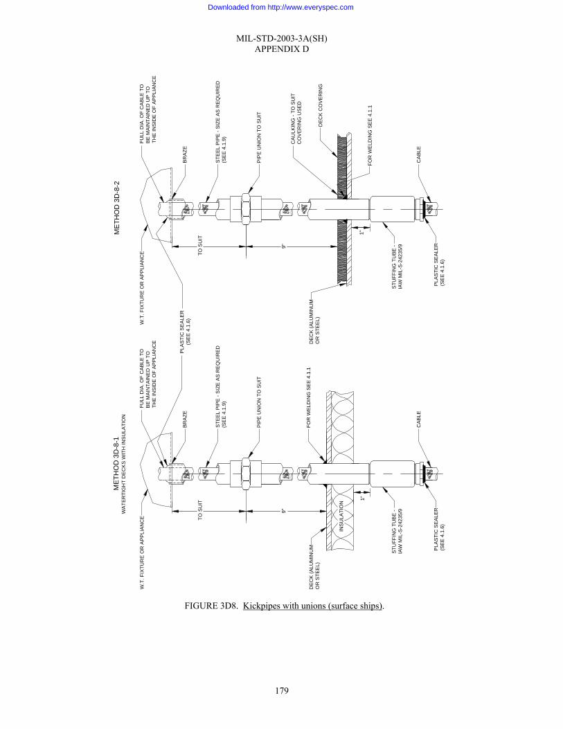
MIL-STD-2003-3A(SH) APPENDIX D
179
FIGURE 3D8. Kickpipes with unions (surface ships).
INS
ULA
TIO
N
FULL
DIA
. OF
CA
BLE
TO
BE
MA
INTA
INE
D U
P TO
THE
INS
IDE
OF
AP
PLIA
NC
E
BR
AZE
STE
EL
PIP
E -
SIZ
E A
S R
EQ
UIR
ED
(SE
E 4
.1.9
)
PIP
E U
NIO
N T
O S
UIT
FOR
WE
LDIN
G S
EE
4.1
.1
CAB
LE
PLA
STI
C S
EA
LER
(SE
E 4
.1.6
)
STU
FFIN
G T
UB
E -
IAW
MIL
-S-2
4235
/99"
TO S
UIT
DE
CK
(ALU
MIN
UM
OR
STE
EL)
1"
W.T
. FIX
TUR
E O
R A
PP
LIA
NC
EFU
LL D
IA. O
F C
AB
LE T
OB
E M
AIN
TAIN
ED
UP
TO
THE
INS
IDE
OF
AP
PLI
ANC
E
BR
AZE
STE
EL
PIP
E -
SIZ
E A
S R
EQ
UIR
ED
(SE
E 4.
1.9)
PIP
E U
NIO
N T
O S
UIT
FOR
WE
LDIN
G S
EE
4.1
.1
CA
BLE
PLA
STI
C S
EA
LER
(SE
E 4
.1.6
)
STU
FFIN
G T
UB
E -
IAW
MIL
-S-2
4235
/99"
TO S
UIT
DE
CK
(ALU
MIN
UM
OR
STE
EL)
1"
PLA
STI
C S
EA
LER
(SE
E 4
.1.6
)
CAU
LKIN
G -
TO S
UIT
CO
VE
RIN
G U
SED
DE
CK
CO
VER
ING
MET
HO
D 3
D-8
-1W
ATE
RTI
GH
T D
EC
KS
WIT
H IN
SU
LATI
ON
W.T
. FIX
TUR
E O
R A
PPL
IAN
CE
MET
HO
D 3
D-8
-2
Downloaded from http://www.everyspec.com

MIL-STD-2003-3A(SH) APPENDIX E
180
GROUP 3E - PENETRATIONS – PRESSURE HULLS, SUBMARINES
E.1 SCOPE
E.1.1 Scope. This appendix describes the installation standard methods for penetration through pressure hulls of submarines.
E.2. APPLICABLE DOCUMENTS
E.2.1 General. The documents listed in this section are specified in sections 3, 4, or 5 of this standard. This section does not include documents cited in other sections of this standard or recommended for additional information or as examples. While every effort has been made to ensure the completeness of this list, document users are cautioned that they must meet all specified requirements of documents cited in sections 3, 4, or 5 of this standard, whether or not they are listed.
E.2.2 Government documents.
E.2.2.1 Specifications, standards, and handbooks. The following specifications, standards, and handbooks form a part of this document to the extent specified herein. Unless otherwise specified, the issues of these documents are those cited in the solicitation or contract.
FEDERAL SPECIFICATIONS
QQ-N-281 - Nickel-Copper Alloy Bar, Rod, Plate, Sheet, Strip, Wire, Forgings, and Structural and Special Shaped Sections
COMMERCIAL ITEM DESCRIPTIONS
A-A-59588 - Rubber, Silicone
DEPARTMENT OF DEFENSE SPECIFICATIONS
MIL-DTL-915 - Cable, Electrical, for Shipboard Use, General Specification for
MIL-C-24231 - Connectors, Plugs, Receptacles, Adapters, Hull Inserts, and Hull Insert Plugs, Pressure-Proof, General Specification for
MIL-C-24231/1 - Connector, Plug, Type I, Molded, Three-, Four-, and Five-Conductor
MIL-C-24231/3 - Connector, Plug, Type I, Molded, Seven- and Nine-Conductor (Straight and 90 Degrees)
MIL-C-24231/4 - Connectors, Plug, Type I, Molded, 14-, 24-, 30-, or 40-Conductor (Straight and 90 Degrees)
MIL-C-24231/18 - Connector, Plug, Type I, Molded, 65-Conductor
MIL-S-24235/16 - Stuffing Tubes, Metal, and Packing Assemblies for Electric Cables, Cable Shearing Valve, Hull, Pressureproof, Symbols 512, 512.1, 513, and 513.1
(Copies of these documents are available online at http://assist.daps.dla.mil/quicksearch/ or from the Standardization Document Order Desk, 700 Robbins Avenue, Building 4D, Philadelphia, PA 19111-5094.)
Downloaded from http://www.everyspec.com

MIL-STD-2003-3A(SH) APPENDIX E
181
E.2.2.2 Other Government documents, drawings, and publications. The following other Government documents, drawings, and publications form a part of this document to the extent specified herein. Unless otherwise specified, the issues of these documents are those cited in the solicitation or contract.
NAVAL SEA SYSTEMS COMMAND (NAVSEA) DRAWINGS
815-1197212 - Electrode,4000 SBM, Sym. 3012
815-1197218 - Fitting, Hull, for AN/BQQ-1, Sym. 538
9000-S6202-1197101 - Tube, Stuffing, PP for SS & TSP Type Cables
(Copies of these documents are available from Commander, Portsmouth Naval Shipyard, ATTN: Code 280.1, Kittery, ME 03904.)
NAVAL SEA SYSTEMS COMMAND (NAVSEA) PUBLICATIONS
T9074-AD-GIB-010/1688 - Fabrication, Welding and Inspection of Submarine Structure; Requirements
(Copies of these documents are available from the Naval Logistics Library, 5450 Carlisle Pike, Mechanicsburg, PA 17055 or online at http://nll.ahf.nmci.navy.mil.)
A.2.3 Non-Government publications. The following documents form a part of this document to the extent specified herein. Unless otherwise specified, the issues of these documents are those cited in the solicitation or contract.
SAE INTERNATIONAL
SAE-AMS-DTL-23053/5 - Insulation Sleeving, Electrical, Heat Shrinkable, Polyolefin, Flexible Crosslinked
SAE-AMS-DTL-23053/18 - Insulation Sleeving, Electrical, Heat Shrinkable, Modified Fluoropolymer, Crosslinked
SAE-AMS-G-4343 - Grease, Pneumatic System
SAE-AS8660 - Silicone Compound NATO Code Number S-736
(Copies of these documents are available from SAE World Headquarters, 400 Commonwealth Drive, Warrendale, PA 15096-0001 or online at www.sae.org.)
E.2.4 Order of precedence. Unless otherwise noted herein or in the contract, in the event of a conflict between the text of this document and the references cited herein, the text of this document takes precedence. Nothing in this document, however, supersedes applicable laws and regulations unless a specific exemption has been obtained.
E.3 REQUIRED EQUIPMENT AND MATERIALS
E.3.1 Required equipment and materials. The required equipment and materials for the proper installation of penetrations through pressure hulls of submarines are as shown in the Appendix E methods.
E.4 NOTES AND PROCEDURES
E.4.1 Dimensions. For figures and tables in this section, all dimensions are in inches unless otherwise noted.
E.4.2 Figures. Table 3EI provides information for the figures in this group.
Downloaded from http://www.everyspec.com

MIL-STD-2003-3A(SH) APPENDIX E
182
TABLE 3EI. Figures for penetrations of submarine pressure hulls.
Figure number Submarine pressure hull penetrations Page
3E1 Cable connections through pressure hulls of submarines 183 3E2 Sealing plugs for hull inserts on submarines 184 3E3 Passing cable through pressure hull of submarines using cable shearing valve 185 3E4 Hull fitting installation for sonar sphere 188 3E5 Passing SS type cable through pressure hull of submarines 190 3E6 Mounting pressure-proof electrodes on submarines 192 3E7 Temporary sealing and securing pressure-proof molded plug assemblies 193
Downloaded from http://www.everyspec.com

MIL-STD-2003-3A(SH) APPENDIX E
183
NOTES: 1. Single and multiple cable connectors shall be installed and inspected in accordance with the applicable
Submarine Maintenance Standard. 2. “O” ring surfaces on hull inserts shall be suitably protected from damage or weld splatter at all times prior to
installation of hull fitting. 3. Dotted line indicates outline for single cable hull fitting. 4. Coat “O” rings and “O” ring surfaces with grease conforming to SAE-AS8660. 5. Remove receptacle caps prior to installation of molded plug assemblies (see note 9). 6. Secure inboard cable in place with cable supports as required. 7. Methods shown herein have been tested and approved for deep diving submarines. 8. Methods for temporary sealing hull inserts and pressure-proof plug assemblies are shown on figure 3E2. 9. When molded plug assemblies are temporarily disconnected, reinstall pressure-proof caps (see note 5 above). 10. Hull insert to be furnished by shipbuilder of a steel compatible with applicable hull. For further detailed
requirements, see MIL-C-24231. 11. Position hull insert to outboard cable runs (multiple hull fittings). Hull insert is to be installed with dowel
pins at zero degrees forward (or parallel to the ship’s centerline) unless otherwise directed by ship’s drawings.
FIGURE 3E1. Cable connections through pressure hulls of submarines.
METHOD 3E-1-1
SEE NOTE 3
OUTBOARD
MOLDED PLUG ASSEMBLYMIL-C-24231 (SEE NOTES 5 AND 9)
HULL FITTING (MULTIPLE)
HULL
INSULATIONHULL INSERT(SEE NOTE 10 AND 11) POSITION TO SUIT OUTBOARD CABLE RUNS,
MULTIPLE HULL FITTING.
INBOARD METHOD ENTERING W.T. ENCLOSUREMETHODS 1B-4-1,1B-4-2, AND 1B-4-3.
BOX RING
"O" RING
SEE METHOD 3C-1-1AS APPLICABLE
BOTTOM WASHER
TUBE BODY
PACKING, TYPE AS REQ'D
FORM SLEEVING AS INDICATEDSUIT AS REQ'D
LOCK NUT
CAP
SLIP WASHERS
SEE NOTE 6
SLEEVING
SEIZING OR BANDING
BUSHING
GLAND NUT
RETAINER RINGLOCK NUTWASHER"O" RING
"O" RING
END VIEW
Downloaded from http://www.everyspec.com

MIL-STD-2003-3A(SH) APPENDIX E
184
TABLE 3E2-I. Quantities for one sealing plug assembly.
Number required - one Insert plug assy.
Insert plug Retaining ring Nut Washer “O” ring * - outboard
“O” ring * - inboard For hull insert
M24321/28-001 M24231/28-010 M24231/5-076 M24231/5-074 M24231/5-075 ARP568-329 ARP568-327 M24231/25-001
M24231/28-002 M24231/28-020 M24231/10-045 M24231/10-042 M24231/10-043 ARP568-334 ARP568-332 M24231/25-002
M24231/28-003 M24231/28-030 M24231/19-014 M24231/19-024 M24231/19-025 ARP568-342 ARP568-339 M24231/25-003
* NOTE: Silicone rubber A-A-59588, Class III. NOTES:
1. Install hull insert sealing plug in accordance with applicable Submarine Maintenance Standard. 2. Hull inserts shall be furnished with sealing plugs in place to protect “O” ring surfaces from damage. Sealing
plugs shall remain in place during welding and shall not be removed until insertion of single or multiple cable hull fitting.
3. Each sealing plug shall be checked with “go” and “no go” gages to ensure interchangeability with hull inserts. 4. For installation of hull fittings and hull inserts, see figure 3E1. 5. Silicone “O” rings are used only when welding in insert buna type “O” rings are required for service
installation.
FIGURE 3E2. Sealing plugs for hull inserts on submarines.
METHOD 3E-2-1M24231/28-001M24231/28-002M24231/28-003
"O" RING
"O" RING
WASHER
NUT, HEX
RING, RETAININGTRUARC OR EQUAL
OUTBOARD
INBOARD
INSERT, HULL
Downloaded from http://www.everyspec.com

MIL-STD-2003-3A(SH) APPENDIX E
185
FIGURE 3E3. Passing cable through pressure hull of submarines using cable shearing valve.
METHOD 3E-3-1
LOCK WASHER
OUTBOARD
SECTION A-A
VALVE BODY
1/8" X 45° BEVEL
HULL
DIM. "X"
INSULATION
LOCKING RING
GASKET (SEENOTE 7) A A
GROMMET
GLAND RINGLOCK WASHER
GLAND NUT
CABLE (SEENOTE 3)
HAND WHEEL
SEE TABLEOF CABLEASSIGNMENT
GLAND NUT
GLAND RING
GROMMET
SEE NOTE 1
SEE NOTE 1
"O" RINGCOAT WITH DC-7
VALVE SEAT(SEE NOTE 4)
BONNET
SHEARING KNIFE
"O" RING
GREASE FITTING
COTTER PIN(SEE NOTE 2)
SAFETY CHAIN
INBOARD
Downloaded from http://www.everyspec.com

MIL-STD-2003-3A(SH) APPENDIX E
186
TABLE 3E3-I. Cable assignment.
Symbol no. Cable O.D. Grommet PC no.
Gland ring PC no. Dim “X”
0.475 46 59 0.510 0.520
47 60
0.545 48 61
512
0.627 0.632
49 62
0.720 50 63 0.750 51 64
512.1
2.062
0.795 0.805
52 65
0.830 0.844
53 66
0.870 54 67
513
0.995 55 68 1.020 56 69 1.115 1.120
57 70
1.150 1.156
58 71
513.1
2.562
FIGURE 3E3. Passing cable through pressure hull of submarines using cable shearing valve - Continued.
Downloaded from http://www.everyspec.com

MIL-STD-2003-3A(SH) APPENDIX E
187
NOTES: 1. Welding shall comply with T9074-AD-GIB-010/1688. 2. Before assembly, drill hole for cotter pin with valve in full open position. Pin must be easily removed. Bend
only enough to prevent falling out. 3. The cable shearing valves are designed for cables in accordance with MIL-DTL-915. 4. If valve seat becomes damaged, it can be reversed and reinstalled with a new valve seat gasket. Removal of
valve seat is accomplished by use of a ⅞-12 stud for symbol no. 512 or a 1⅜-12 stud for symbol no. 513. 5. Terminate inboard cable in a junction box, which will be located in the vicinity of the shear valve. 6. For specifications, see MIL-S-24235/16. 7. Cement gasket to valve seat and body.
FIGURE 3E3. Passing cable through pressure hull of submarines using cable shearing valve - Continued.
Downloaded from http://www.everyspec.com

MIL-STD-2003-3A(SH) APPENDIX E
188
NOTES: 1. Install hull fitting in accordance with applicable Submarine Maintenance Standard and the applicable drawing
for the ship class. 2. Hull insert shall be machined to finished dimensions as shown under Method 3E-4-2 after all welding has
been completed on sonar sphere.
FIGURE 3E4. Hull fitting installation for sonar sphere.
MET
HO
D 3
E-4-
1
CA
BLE
MA
RK
ER
(SE
E N
OTE
4)
OU
TBO
AR
D
CA
BLE
EN
D
GLA
ND
NU
T
FITT
ING
LOC
K W
AS
HE
R
GLA
ND
RIN
G
PA
CK
ING
HE
X N
UT
LOC
K W
AS
HE
R
"O" R
ING
- L
IGH
TLY
LU
BR
ICA
TE W
ITH
SIL
ICO
NE
BA
SE
LU
BR
ICA
NT,
SA
E-A
S86
60,
AT
AS
SE
MBL
Y
HU
LL IN
SE
RT
(SE
E N
OTE
S 1
, 2, A
ND
3)
FOR
WE
LD S
IZE
SE
E 4
.1.1
SO
NA
R S
PH
ER
E
EX
TEN
SIO
N F
ITTI
NG
AN
/BQ
Q-1
TR
AN
SD
UC
ER
BA
SE
(FU
RN
ISH
ED
BY
CO
NTR
AC
TOR
)
GLA
ND
NU
T
LOC
K W
AS
HE
RG
LAN
D R
ING
PA
CK
ING
INB
OA
RD
1/8"
R
2.24
8" D
IA2.
252"
1.61
5" D
IA1.
617"
1/16
" R
0.00
8" R
ME
THO
D 3
E-4-
2
HU
LL IN
SE
RT
DE
TAIL
S(S
EE
NO
TES
1, 2
, AN
D 3
)
1.31
1"1.
313"
1.49
9"1.
501" 3"
AP
PR
OX
.
1.37
4" D
IA1.
376"
6363125
Downloaded from http://www.everyspec.com

MIL-STD-2003-3A(SH) APPENDIX E
189
NOTES (continued): 3. Hull insert material shall be Ni-CU Monel, QQ-N-281, Class A, hot rolled. Dimensions shown are applicable
after welding in sonar sphere and after machining to accept PCs 1, 3, and 9 of Drawing 815-1197218. Outer diameter shall be such as to provide adequate compensation. Hull inserts are to be furnished by the shipbuilder.
4. Cable marker shall consist of heat shrinkable tubing-white in accordance with SAE-AMS-DTL-23053/5, Class 1, with cable designation stamped as required and then covered by a clear heat shrinkable tubing in accordance with SAE-AMS-DTL-23053/18. This method may be used as an alternate to the standard method of marking sonar cables.
5. See the ship SDI for configuration.
FIGURE 3E4. Hull fitting installation for sonar sphere - Continued.
Downloaded from http://www.everyspec.com

MIL-STD-2003-3A(SH) APPENDIX E
190
FIGURE 3E5. Passing SS type cable through pressure hull of submarines.
ME
THO
D 3
E-5
-1
SE
E N
OTE
7
OU
TBO
ARD
1
12
2
3
3
4
4
5
5
6
6
7
7
INBO
AR
D
GLA
ND
NU
TLO
CK
WA
SH
ERG
LAN
D R
ING
GR
OM
MET
LUB
RIC
ATE
TH
REA
DS
WIT
H M
OLY
KOTE
GR
EAS
E O
R E
QU
AL
PLA
STI
C S
EALE
R1/
8" T
O 1
/4" G
REA
TER
TH
AN
O.D
. OF
HU
LL F
ITTI
NG
SE
E N
OTE
1
1 3/
4"IN
SU
LATI
ON
HU
LLSE
E N
OTE
S 8
AN
D 9
BOD
Y
SE
E N
OTE
8
RE
TAIN
ER P
LATE
PA
CKI
NG
PO
SIT
ION
PLA
TE
SPR
ING
WA
SHER
GLA
ND
NU
TS
EE
NO
TE 2
SYM
BOL
2448
.1LO
CAT
E T
O S
UIT
OU
TBO
ARD
RU
NS
SYM
BO
L 24
48.2
AN
DS
YMBO
L 24
48.3
VIE
W S
HO
WIN
G T
HE
REL
ATI
ON
SHIP
OF
STU
FFIN
GTU
BES
TO H
OLE
LO
CAT
ION
S IN
PAC
KIN
G, R
ETAI
NER
AND
PO
SITI
ON
PLA
TES
, AN
D A
LSO
TH
E SE
QU
ENC
EO
F SI
ZES
TO B
E F
OLL
OW
ED.
Downloaded from http://www.everyspec.com

MIL-STD-2003-3A(SH) APPENDIX E
191
TABLE 3E5-I. Application.
Symbol Total number of cables For cable types
2448.1 2 to 7 0.365 to 0.620 dia. in any combination 2448.2 8 DSS-2 0.365 to 0.390 dia. cable only 2448.3 8 0.425 to 0.500 dia. only in any combination
TABLE 3E5-II. Cable and packing assignments from drawing 9000-S6202-1197101.
Grommet Cable type Cable O.D.
Sym. no. PC no. Color coding for grommets
Stuffing tube symbol no.
DSS-2 0.365 to 0.390 2447.1 2 3 blue dots DSS-3 DSS-4 TSS-4 FSS-2
0.480 to 0.500 2447.3 6 2 yellow dots 2446.1
FSS-4 0.600 to 0.625 2447.4 12 4 green dots 2446.2 NOTES:
1. Prior to welding, fitting shall be disassembled by removing interior rubber packing. Plugs shall remain in outboard tubes until cables are installed.
2. Turn gland nut down so that this dimension is between 19⁄32 and 23⁄32 at assembly with cables depending on type and number.
3. Check color coding on packing grommets and measure O.D. of cables to ensure that the grommets are in accordance with sizes listed in table 3E5-II.
4. Thread cables in place, maintaining proper alignment, through positioning plate, packing, retainer plate, grommet, and associated stuffing tube.
5. Secure cables in outboard stuffing tubes with gland ring, lockwasher, and gland nut in sequence indicated. Gland nuts shall be tightened down metal-to-metal.
6. Tighten inboard gland nut in place as indicated. 7. Turn gland nut down metal-to-metal at assembly. 8. Sealing plugs furnished with hull fitting shall remain in place until cables are installed. 9. For reference on pressure-proof hull fitting and stuffing tube assembly, see MIL-C-24231 and tube drawing
9000-S6202-1197101.
FIGURE 3E5. Passing SS type cable through pressure hull of submarines - Continued.
Downloaded from http://www.everyspec.com

MIL-STD-2003-3A(SH) APPENDIX E
192
NOTES: 1. Upper and lower electrode surfaces shall be free from contaminants to ensure circuit when immersed in water. 2. Surfaces of Teflon insulator shall be protected during installation to prevent damage and/or contamination by
dirt, grease, etc. 3. Coat “O” rings and “O” ring surfaces with grease conforming to SAE-AMS-G-4343 (DC7). 4. Remove receptacle cap furnished with electrode assembly prior to installation of molded plug assembly. 5. This electrode is designed to withstand 2000 psi hydrostatic pressure against either the electrode or the
receptacle side. 6. This drawing was developed from BUSHIPS drawing 815-1197212.
FIGURE 3E6. Mounting pressure-proof electrodes on submarines.
ME
THO
D 3
E-6
-1
UPP
ER
ELE
CTR
OD
E(S
EE
NO
TE 1
)
SYM
BO
L 30
12
TEFL
ON
INSU
LATO
R(S
EE
NO
TE 2
)
ELE
CTR
OD
E AS
SEM
BLY
"O" R
ING
(SEE
NO
TE 3
)
1" M
INIM
UM
LOC
K W
AS
HER
MO
UN
TIN
G B
OLT
,M
ATER
IAL
NI-C
U.
MO
LDE
D P
LUG
, DW
G 8
15-1
1972
12-2
0(S
EE
NO
TE 4
)
"O" R
ING
(SEE
NO
TE 3
)
CAB
LE, F
SS-
2LE
NG
TH A
S R
EQ
UIR
ED
.
SH
IELD
AS
SEM
BLY
1.87
5"R
EA
M
1.56
2" R
1/2"
-13
UN
C-2
B, 5
/8" D
EEP
6 H
OLE
S, 6
0° A
PAR
T
1/16
" x 3
0° C
HA
MFE
R
ME
THO
D 3
E-6
-2S
YMB
OL
3012
.1
MO
UN
TIN
G D
IME
NS
ION
SV
IEW
AT
A-A
MO
UN
TIN
G B
OLT
S TO
BE
1/2"
-13
UN
C-2
A
AA
LOW
ER
ELE
CTR
OD
E(S
EE
NO
TE 1
)
Downloaded from http://www.everyspec.com

MIL-STD-2003-3A(SH) APPENDIX E
193
TABLE 3E7-I. Sealing plug assembly.
Molded plug specification Symbol number Sealing plug assembly
713 713.5
MIL-C-24231/1-020
713.1 MIL-C-24231/3-020 713.2 713.3 713.4
MIL-C-24231/4-020
1139
MIL-C-24231
1118 MIL-C-24231/18-020
FIGURE 3E7. Temporary sealing and securing pressure-proof molded plug assemblies.
METHOD 3E-7-1
3/8" WELD STUD
SEALING PLUG
"O" RING
MOLDED PLUG ASSEMBLY
3/8"-16 CRES MACH SCR AND LOCK WASHER
METHOD 3E-7-2ALTERNATE METHOD
LENGTH AS REQ'D.
TEMPLATE TO SUIT
SHIP'S STRUCTURE
SEALING PLUG
LENGTHAS REQ'D.
BRACKET (STEEL 3/16" THK x 1 1/2" WIDE)
Downloaded from http://www.everyspec.com

MIL-STD-2003-3A(SH) APPENDIX E
194
NOTES: 1. Typical methods shown hereon are for information and guidance to installing activities for sealing and/or
securing of pressure-proof pin type molded connectors that have been temporarily disconnected from their associated receptacle.
2. Temporary sealing of pin connector hull fittings or receptacles are shown on figures 3E1 and 3E2. 3. Cables shall be properly secured or protected to prevent damage from chaffing, weld splatter, and/or other
hazards.
FIGURE 3E7. Temporary sealing and securing pressure-proof molded plug assemblies - Continued.
Downloaded from http://www.everyspec.com

MIL-STD-2003-3A(SH)
195
Preparing activity:
Navy – SH (Project SESS-2008-004)
NOTE: The activities listed above were interested in this document as of the date of this document. Since organizations and responsibilities can change, you should verify the currency of the information above using the ASSIST Online database at http://assist.daps.dla.mil.
Downloaded from http://www.everyspec.com