department of defense standard...
TRANSCRIPT
INCH-POUND MIL-STD-2003-5A(SH) 3 September 2009 SUPERSEDING DOD-STD-2003-5(SH) 24 June 1987
DEPARTMENT OF DEFENSE STANDARD PRACTICE
ELECTRIC PLANT INSTALLATION STANDARD METHODS FOR
SURFACE SHIPS AND SUBMARINES (CONNECTORS)
Downloaded from http://www.everyspec.com

MIL-STD-2003-5A(SH)
ii
FOREWORD
1. This standard is approved for use by the Naval Sea Systems Command, Department of the Navy, and is available for use by all Departments and Agencies of the Department of Defense.
2. This standard disseminates up-to-date information detailing requirements for standard installation methods employed for submarine and surface ship electrical distribution systems.
3. These criteria apply to work on a specific ship or ships only when invoked by the Ship Specifications or similar contractual documents.
4. These criteria are for application to new construction, conversion, and alteration of existing ships.
5. Considering the magnitude of this standard, along with the changing requirements imposed on the Electric Plant, it is inevitable that changes will be required to update these criteria. Therefore, as comments arise, they should be forwarded to Naval Sea Systems Command (NAVSEA) 05Z3 to keep this standard as current as possible through subsequent revisions. Revisions will be accomplished by the issuance of additional or revised figures to be inserted in the basic standard parts. Superseded pages may be retained for reference if so desired.
6. Comments, suggestions, or questions on this document should be addressed to Commander, Naval Sea Systems Command, ATTN: SEA 05M2, 1333 Isaac Hull Avenue, SE, Stop 5160, Washington Navy Yard DC 20376-5160 or emailed to [email protected], with the subject line “Document Comment”. Since contact information can change, you may want to verify the currency of this address information using the ASSIST Online database at http://assist.daps.dla.mil.
Downloaded from http://www.everyspec.com

MIL-STD-2003-5A(SH)
iii
CONTENTS
PARAGRAPH PAGE
1. SCOPE......................................................................................................................................................................1 1.1 Scope.................................................................................................................................................................1
1.1.1 Application...............................................................................................................................................1 2. APPLICABLE DOCUMENTS ................................................................................................................................1
2.1 General..............................................................................................................................................................1 2.2 Government documents ....................................................................................................................................1
2.2.1 Specifications, standards, and handbooks ................................................................................................1 2.3 Order of precedence..........................................................................................................................................1
3. DEFINITIONS .........................................................................................................................................................1 4. GENERAL REQUIREMENTS................................................................................................................................2
4.1 Instructions for use of MIL-STD-2003-5..........................................................................................................2 5. DETAILED REQUIREMENTS...............................................................................................................................2 6. NOTES .....................................................................................................................................................................2
6.1 Intended use ......................................................................................................................................................2 6.2 Acquisition requirements ..................................................................................................................................2 6.3 Designation of electric plant installation standard methods figures..................................................................2 6.4 Subject term (key word) listing.........................................................................................................................3 6.5 Changes from previous issue ............................................................................................................................3
APPENDIX A Cable Lead Preparation .......................................................................................................................4 APPENDIX B MIL-C-81511 Series 1 and 2 Gang Contact Release Connector Assembly Procedure .....................88 APPENDIX C MIL-DTL-5015 Connectors ............................................................................................................112 APPENDIX D MIL-DTL-26482 Connectors ..........................................................................................................132 APPENDIX E MIL-DTL-28840 Connectors ..........................................................................................................145 APPENDIX F MIL-DTL-27599 Connectors ..........................................................................................................155 APPENDIX G MIL-DTL-22992 Connectors ..........................................................................................................165 APPENDIX H MIL-DTL-38999 Connectors ..........................................................................................................172
Downloaded from http://www.everyspec.com

MIL-STD-2003-5A(SH)
1
1. SCOPE
1.1 Scope. This standard covers standard methods for connector fabrication on surface ships and submarines.
1.1.1 Application. These installation methods are to be used by all installing activities. These methods do not identify ship or type but do establish minimum standards of acceptance for Naval ships. It is the responsibility of the user activity to determine which method satisfies their requirements. It does not authorize relaxation of any requirement specifically invoked by new construction, conversion, overhaul, or refurbishment contracts. In instances where deviated design requirements (for example, ship type, ship class, and so forth) conflict with the requirements of this standard, the requirements of this standard govern. Any deviation for electric plant installation identified in this standard is to be submitted to NAVSEA 05Z3 for resolution.
2. APPLICABLE DOCUMENTS
2.1 General. The documents listed in this section are specified in sections 3, 4, or 5 of this standard. This section does not include documents cited in other sections of this standard or recommended for additional information or as examples. While every effort has been made to ensure the completeness of this list, document users are cautioned that they must meet all specified requirements of documents cited in sections 3, 4, or 5 of this standard, whether or not they are listed.
2.2 Government documents.
2.2.1 Specifications, standards, and handbooks. The following specifications, standards, and handbooks form a part of this document to the extent specified herein. Unless otherwise specified, the issues of these documents are those cited in the solicitation or contract.
DEPARTMENT OF DEFENSE SPECIFICATIONS
MIL-DTL-5015 - Connectors, Electrical, Circular Threaded, AN Type, General Specification for
MIL-DTL-22992 - Connectors, Plugs and Receptacles, Electrical, Waterproof, Quick Disconnect, Heavy Duty Type, General Specification for
MIL-DTL-26482 - Connectors, Electrical, (Circular, Miniature, Quick Disconnect, Environment Resisting), Receptacles and Plugs, General Specification for
MIL-DTL-27599 - Connectors, Electrical, Circular, Miniature, High Density, Quick Disconnect, Environment Resistant, Solder Contacts, General Specification for
MIL-DTL-28840 - Connectors, Electrical, Circular, Threaded, High Density, High Shock, Shipboard, Class D, General Specification for
MIL-DTL-38999 - Connectors, Electrical Circular, Miniature, High Density, Quick Disconnect (Bayonet, Threaded and Breech Coupling), Environment Resistant, Removable Crimp and Hermetic Solder Contacts, General Specification for
MIL-C-81511 - Connectors, Electrical, Circular, High Density, Quick Disconnect, Environment Resisting: and Accessories General Specification for
(Copies of these documents are available online at http://assist.daps.dla.mil/quicksearch/ or from the Standardization Document Order Desk, 700 Robbins Avenue, Building 4D, Philadelphia, PA 19111-5094.)
2.3 Order of precedence. Unless otherwise noted herein or in the contract, in the event of a conflict between the text of this document and the references cited herein, the text of this document takes precedence. Nothing in this document, however, supersedes applicable laws and regulations unless a specific exemption has been obtained.
3. DEFINITIONS
Refer to figure 5A12.
Downloaded from http://www.everyspec.com
MIL-STD-2003-5A(SH)
2
4. GENERAL REQUIREMENTS
4.1 Instructions for use of MIL-STD-2003-5. This standard is designed to be utilized by a connector assembly technician and is formatted to be utilized as follows:
a. Determine the governing specification for the connector being assembled. b. Proceed to the applicable Connector Assembly Procedure (figure 5B1, 5C1, and so forth) and review to
determine tools and materials required. Each group is designed to assemble a connector starting with the basic components and proceeding in a step-by-step manner to the completed assembly.
c. Instructions shown on figures 5A1 through 5A14 identify a sequence of processes common to any connector assembly (that is, lead stripping, crimping, soldering, and so forth). The conduct of these procedures will be sequenced by the Connector Assembly Procedures. The technician should review these procedures to become familiar with their content.
d. Terminate the connector/backshell to the cable utilizing the appropriate Connector Assembly Procedure. e. The technician should keep in mind that to install a cable with connectors on board a ship, in most
instances, at least one end will need to be routed through a kickpipe, standpipe, stuffing tube, etc and thus cannot have a connector installed prior to routing on-board the ship.
These procedures are designed for use with military specification connectors and backshells. Commercial substitutions may result in deviations from these procedures. Manufacturer assembly instructions should be consulted in these cases. Equivalent tooling and materials may be substituted provided the intent of the specification is achieved.
5. DETAILED REQUIREMENTS
(See figures.)
6. NOTES
(This section contains information of a general or explanatory nature that may be helpful, but is not mandatory.)
6.1 Intended use. This standard specifies the requirements for Standard Methods to be employed both on surface ships and submarines. Standard Methods identified for electric plant installation are intended for new construction, conversion, and alteration of existing ships.
6.2 Acquisition requirements. Acquisition documents should specify the following:
a. Title, number, and date of this standard.
6.3 Designation of electric plant installation standard methods figures. The electric plant installation standard method MIL-STD-2003-5 contains drawings that depict Standard Methods that are applicable for general electric plant installation on both surface ships and submarines. Each drawing has been assigned a figure number. The methods shown on the figures are grouped together providing similar functions. These groups are:
MIL-STD-2003-5 (Connectors) Group A. Cable Lead Preparation
B. MIL-C-81511 Series 1 and 2 Gang Contact Release Connector Assembly Procedure
C. MIL-DTL-5015 Connectors
D. MIL-DTL-26482 Connectors
E. MIL-DTL-28840 Connectors
F. MIL-DTL-27599 Connectors
G. MIL-DTL-22992 Connectors
H. MIL-DTL-38999 Connectors
The methods shown on the figures are identified by the following alphanumeric designation system:
Downloaded from http://www.everyspec.com
MIL-STD-2003-5A(SH)
3
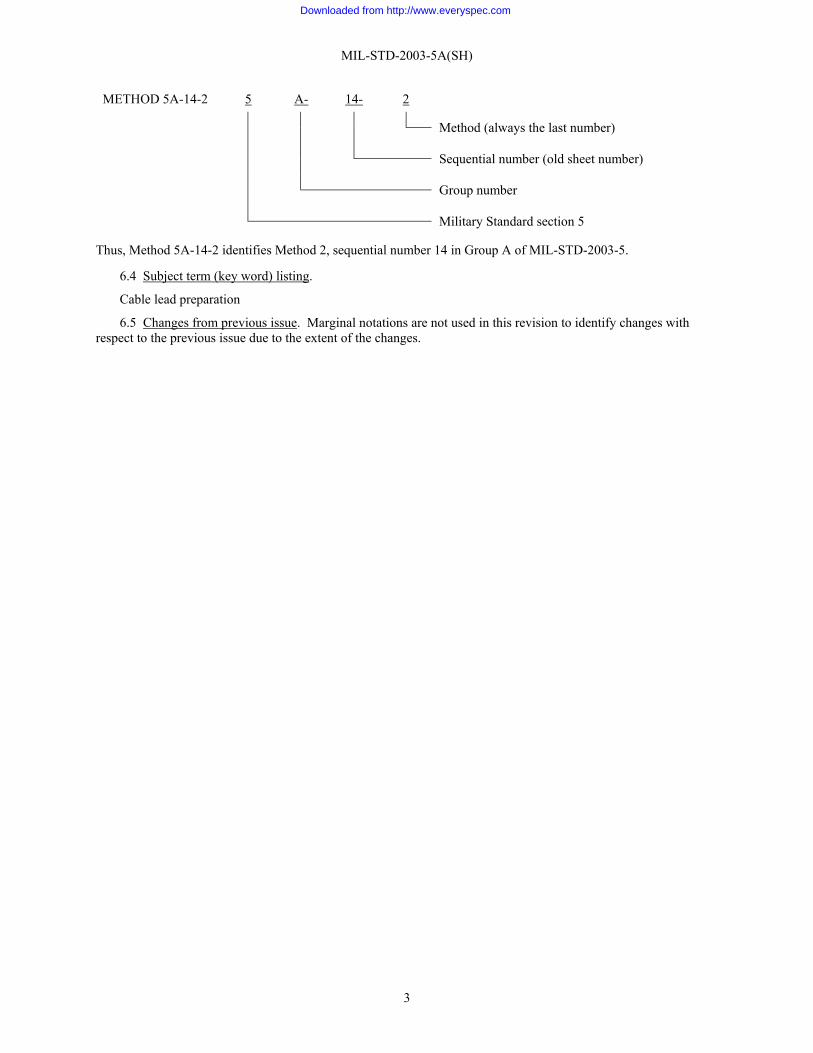
METHOD 5A-14-2 5 A- 14- 2 Method (always the last number)
Sequential number (old sheet number)
Group number
Military Standard section 5
Thus, Method 5A-14-2 identifies Method 2, sequential number 14 in Group A of MIL-STD-2003-5.
6.4 Subject term (key word) listing.
Cable lead preparation
6.5 Changes from previous issue. Marginal notations are not used in this revision to identify changes with respect to the previous issue due to the extent of the changes.
Downloaded from http://www.everyspec.com

MIL-STD-2003-5A(SH) APPENDIX A
4
GROUP 5A - CABLE LEAD PREPARATION
A.1 SCOPE
A.1.1 Scope. This appendix describes procedures for the preparation of leads for electrical connectors used aboard naval ships and submarines.
A.2 APPLICABLE DOCUMENTS
A.2.1 General. The documents listed in this section are specified in this appendix. This section does not include documents cited in other sections of this standard or recommended for additional information or as examples. While every effort has been made to ensure the completeness of this list, document users are cautioned that they must meet all specified requirements of documents cited in this appendix, whether or not they are listed.
A.2.2 Government documents.
A.2.2.1 Specifications, standards, and handbooks. The following specifications, standards, and handbooks form a part of this document to the extent specified herein. Unless otherwise specified, the issues of these documents are those cited in the solicitation or contract.
FEDERAL SPECIFICATIONS
MMM-A-189 - Adhesive, Synthetic-Rubber, Thermoplastic, General Purpose
TT-I-735 - Isopropyl Alcohol
COMMERCIAL ITEM DESCRIPTIONS
A-A-52506 - Clamps, Hose
DEPARTMENT OF DEFENSE SPECIFICATIONS
MIL-DTL-915 - Cable, Electrical, for Shipboard Use, General Specification for
MIL-DTL-5015 - Connectors, Electrical, Circular Threaded, AN Type, General Specification for
MIL-DTL-22520 - Crimping Tools, Wire Termination, General Specification for
MIL-C-22520/5 - Crimping Tools, Terminal, Hand, Wire Termination, Large for Coaxial, Shielded Contacts and Ferrules, Terminal Lugs, Splices and End Caps
MIL-C-22520/6 - Crimping Tools, Terminal, Hand, Wire Terminations; In-Service Inspection Gages
MIL-C-22520/10 - Crimping Tools, Terminal, Hand, Wire Termination, Small, for Coaxial, Shielded Contacts, Ferrules, Terminal Lugs, Splices, and End Caps
MIL-DTL-22992 - Connectors, Plugs and Receptacles, Electrical, Waterproof, Quick Disconnect, Heavy Duty Type, General Specification for
MIL-DTL-24643 - Cables and Cords, Electric, Low Smoke, for Shipboard Use, General Specification for
MIL-DTL-26482 - Connectors, Electrical, (Circular, Miniature, Quick Disconnect, Environment Resisting), Receptacles and Plugs, General Specification for
MIL-DTL-27599 - Connectors, Electrical, Circular, Miniature, High Density, Quick Disconnect, Environment Resistant, Solder Contacts, General Specification for
MIL-DTL-28840 - Connectors, Electrical, Circular, Threaded, High Density, High Shock, Shipboard, Class D, General Specification for
Downloaded from http://www.everyspec.com
MIL-STD-2003-5A(SH) APPENDIX A
5
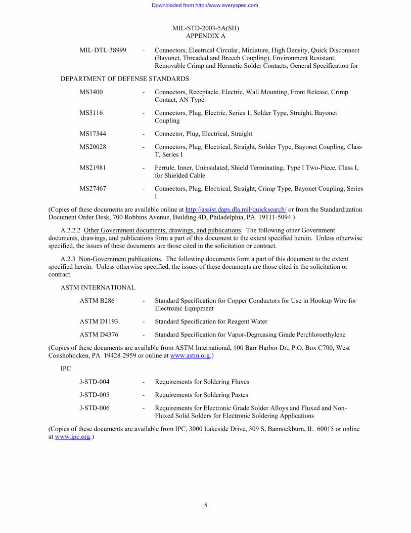
MIL-DTL-38999 - Connectors, Electrical Circular, Miniature, High Density, Quick Disconnect (Bayonet, Threaded and Breech Coupling), Environment Resistant, Removable Crimp and Hermetic Solder Contacts, General Specification for
DEPARTMENT OF DEFENSE STANDARDS
MS3400 - Connectors, Receptacle, Electric, Wall Mounting, Front Release, Crimp Contact, AN Type
MS3116 - Connectors, Plug, Electric, Series 1, Solder Type, Straight, Bayonet Coupling
MS17344 - Connector, Plug, Electrical, Straight
MS20028 - Connectors, Plug, Electrical, Straight, Solder Type, Bayonet Coupling, Class T, Series I
MS21981 - Ferrule, Inner, Uninsulated, Shield Terminating, Type I Two-Piece, Class I, for Shielded Cable
MS27467 - Connectors, Plug, Electrical, Straight, Crimp Type, Bayonet Coupling, Series I
(Copies of these documents are available online at http://assist.daps.dla.mil/quicksearch/ or from the Standardization Document Order Desk, 700 Robbins Avenue, Building 4D, Philadelphia, PA 19111-5094.)
A.2.2.2 Other Government documents, drawings, and publications. The following other Government documents, drawings, and publications form a part of this document to the extent specified herein. Unless otherwise specified, the issues of these documents are those cited in the solicitation or contract.
A.2.3 Non-Government publications. The following documents form a part of this document to the extent specified herein. Unless otherwise specified, the issues of these documents are those cited in the solicitation or contract.
ASTM INTERNATIONAL
ASTM B286 - Standard Specification for Copper Conductors for Use in Hookup Wire for Electronic Equipment
ASTM D1193 - Standard Specification for Reagent Water
ASTM D4376 - Standard Specification for Vapor-Degreasing Grade Perchloroethylene
(Copies of these documents are available from ASTM International, 100 Barr Harbor Dr., P.O. Box C700, West Conshohocken, PA 19428-2959 or online at www.astm.org.)
IPC
J-STD-004 - Requirements for Soldering Fluxes
J-STD-005 - Requirements for Soldering Pastes
J-STD-006 - Requirements for Electronic Grade Solder Alloys and Fluxed and Non-Fluxed Solid Solders for Electronic Soldering Applications
(Copies of these documents are available from IPC, 3000 Lakeside Drive, 309 S, Bannockburn, IL 60015 or online at www.ipc.org.)
Downloaded from http://www.everyspec.com
MIL-STD-2003-5A(SH) APPENDIX A
6
NATIONAL AEROSPACE STANDARDS COMMITTEE (NA/NAS)
NASM20995 - Wire, Safety or Lock
(Copies of this document are available from Aerospace Industries Association, 1250 Eye Street NW, Washington, DC 20005-3924 or online at www.aia-aerospace.org.)
SAE INTERNATIONAL
SAE-AS21608 - Ferrule, Shield Terminating, Crimp Style
SAE-AMS-DTL-23053 - Insulation Sleeving, Electrical, Heat Shrinkable, General Specification for
SAE-AMS-DTL-23053/5 - Insulation Sleeving, Electrical, Heat Shrinkable, Polyolefin, Flexible Crosslinked
SAE-AMS-DTL-23053/15 - Insulation Sleeving, Electrical, Heat Shrinkable, Polyolefin, Heavy-Wall, Coated, Flexible, Outer Wall Crosslinked
SAE-AS81531 - Marking of Electrical Insulating Materials
SAE-AS81765/1 - Insulating Components, Molded, Electrical, Heat Shrinkable Polyolefin, Crosslinked, Semi-Rigid and Flexible
SAE-AS83519 - Shield Termination, Solder Style, Insulated, Heat-Shrinkable, Environment Resistant General Specification for
SAE-AS85049 - Connector Accessories, Electrical General Specification For
SAE-AS85049/1 - Connector Accessories, Electrical, Backshell Environmental, Cable Sealing, Straight, Grounding (Without Strain Relief), Category 1c (for Mil-C-5015 Solder Type, V Thread of Ms310x Classes A, B. C Or K Connectors)
SAE-AS85049/2 - Connector Accessories, Electrical, Backshell, Environmental, Cable Sealing, Straight, Category 1C (for MIL-DTL-5015 Solder Type, V Thread of MS310X Classes A, B, C or K Connectors)
SAE-AS85049/41 - Connector Accessories, Electrical, Non-Environmental, Strain Relief, Straight, Category 4C (for MIL-DTL-5015 General Duty 'A' Endbell and AS85049 Accessories)
SAE-AS85049/42 - Connector Accessories, Electrical, Nonenvironmental, Strain Relief, Straight, Category 4A (for MIL-DTL-5015 Solder Type, V Thread of MS310X Classes A, B, C or K Connectors)
(Copies of these documents are available from SAE World Headquarters, 400 Commonwealth Drive, Warrendale, PA 15096-0001 or online at www.sae.org.)
A.2.4 Order of precedence. Unless otherwise noted herein or in the contract, in the event of a conflict between the text of this document and the references cited herein, the text of this document takes precedence. Nothing in this document, however, supersedes applicable laws and regulations unless a specific exemption has been obtained.
A.3 REQUIRED EQUIPMENT AND MATERIALS
A.3.1 Required equipment and materials. The required equipment and materials are specified in the standard methods of this section.
A.4 NOTES AND PROCEDURES
A.4.1 Dimensions. For figures and tables in this section, all dimensions are in inches unless otherwise noted.
Downloaded from http://www.everyspec.com
MIL-STD-2003-5A(SH) APPENDIX A
7
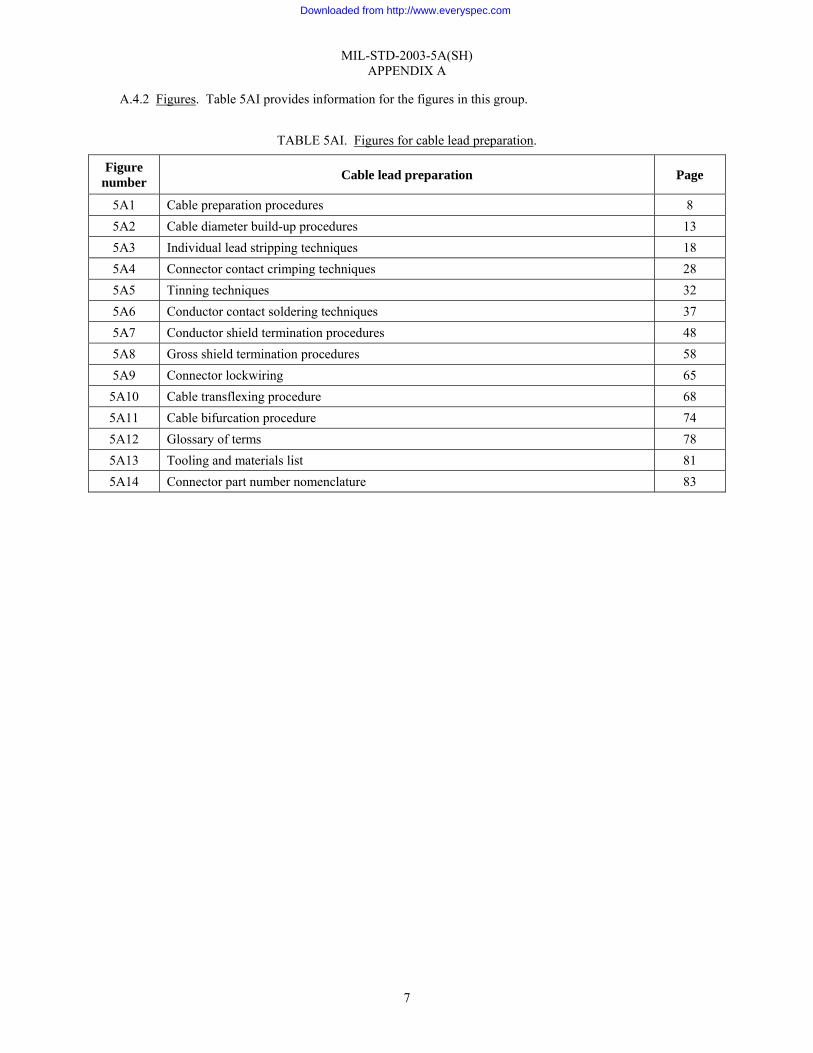
A.4.2 Figures. Table 5AI provides information for the figures in this group.
TABLE 5AI. Figures for cable lead preparation.
Figure number Cable lead preparation Page
5A1 Cable preparation procedures 8 5A2 Cable diameter build-up procedures 13 5A3 Individual lead stripping techniques 18 5A4 Connector contact crimping techniques 28 5A5 Tinning techniques 32 5A6 Conductor contact soldering techniques 37 5A7 Conductor shield termination procedures 48 5A8 Gross shield termination procedures 58 5A9 Connector lockwiring 65
5A10 Cable transflexing procedure 68 5A11 Cable bifurcation procedure 74 5A12 Glossary of terms 78 5A13 Tooling and materials list 81 5A14 Connector part number nomenclature 83
Downloaded from http://www.everyspec.com
MIL-STD-2003-5A(SH) APPENDIX A
8
Cable preparation procedures: 1. Ensure the cable is the correct type as specified on the applicable cabling diagram. 2. Measure the cable to the required length.
a. When the connector is prefabricated in the shop, add 5' or 5 percent, whichever is greater. b. When measuring the cable to terminate at equipment onboard, ensure that sufficient length exists to allow
for at least one, but where practicable, three re-terminations of the connector contacts. Ensure that the required cable bend radius is maintained.
3. Visually inspect the cable jacket for deformities, cuts, or punctures. 4. Wipe the cable jacket or armor, if present, with an approved solvent from table 5A1-I in order to remove
grease, oil, dirt, and other debris in the area where the connector and backshell will be installed.
TABLE 5A1-I. Approved solvents.
Solvent Specification
Isopropyl alcohol TT-I-735 Perchloroethyene ASTM D4376 Reagent water (Type II) ASTM D1193 Detergent cleaners As approved by the government
procuring activity
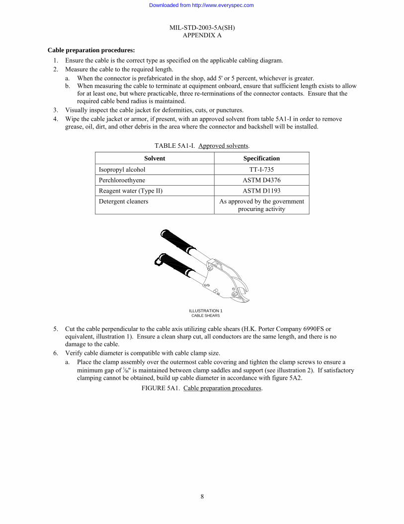
5. Cut the cable perpendicular to the cable axis utilizing cable shears (H.K. Porter Company 6990FS or
equivalent, illustration 1). Ensure a clean sharp cut, all conductors are the same length, and there is no damage to the cable.
6. Verify cable diameter is compatible with cable clamp size. a. Place the clamp assembly over the outermost cable covering and tighten the clamp screws to ensure a
minimum gap of 1⁄16" is maintained between clamp saddles and support (see illustration 2). If satisfactory clamping cannot be obtained, build up cable diameter in accordance with figure 5A2.
FIGURE 5A1. Cable preparation procedures.
ILLUSTRATION 1CABLE SHEARS
Downloaded from http://www.everyspec.com

MIL-STD-2003-5A(SH) APPENDIX A
9
NOTE: For armored cable, prepare the cable using steps 7 through 15. For unarmored cable, prepare the cable using steps 8 through 15.
Cable preparation procedures (continued): 7. Armor preparation, if present:
CAUTION: Do not damage the cable jacket beneath the armor. a. Backshell without armor clinching RFI ferrules (PC 6 and 7).
(1) Measure the length of the assembled backshell (PC 2 through 9) from the connector end to the front end of the clamp saddle (PC 9) (see illustration 3). NOTE: On angled backshells, measure the center radius dimension.
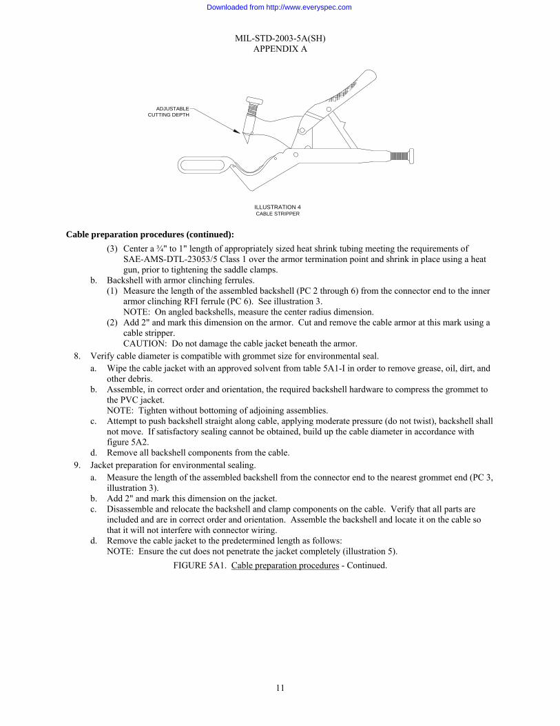
(2) Add 2" and mark this dimension on the armor. Cut and remove the cable armor at this mark using a cable stripper (see illustration 4).
FIGURE 5A1. Cable preparation procedures - Continued.
TORQUE SCREWDRIVERCABLE
MINIMUM 1/16" GAP
CLAMP BARS
CENTERING POST
ILLUSTRATION 2
Downloaded from http://www.everyspec.com

MIL-STD-2003-5A(SH) APPENDIX A
10
FIGURE 5A1. Cable preparation procedures - Continued.
PC
1C
ON
NE
CTO
R P
LUG
PC
2S
LEEV
E A
SSE
MB
LY
PC
3G
RO
MM
ETPC
4G
RO
MM
ET
FOLL
OW
ER
PC
5R
EA
R A
DAP
TER
PC
6A
RM
OR
CIN
CH
ING
RFI
FE
RR
ULE
S (I
NN
ER
)
PC
8C
LAM
P A
SSE
MBL
Y
PC
7A
RM
OR
CIN
CH
ING
RFI
FE
RR
ULE
S (O
UTE
R)
PC
9C
LAM
P S
AD
DLE
S
FRO
NT
END
OF
CLA
MP
SA
DD
LE
ILLU
STR
ATI
ON
3TY
PIC
AL C
ON
NEC
TOR
ASS
EMB
LY
THE
SE
UN
ITS
AR
E N
OT
PR
OV
IDE
D W
ITH
ALL
CO
NN
EC
TOR
TYP
ES.
WH
EN
NO
T P
RO
VID
ED, U
SE
STE
P 7
.1 F
OR
AR
MO
RP
RE
PA
RA
TIO
N A
ND
INS
TALL
CLA
MP
AS
SEM
BLY
PC
. 8 O
N T
HR
EAD
OF
SLEE
VE
ASS
EM
BLY
PC
. 2.
Downloaded from http://www.everyspec.com
MIL-STD-2003-5A(SH) APPENDIX A
11
Cable preparation procedures (continued): (3) Center a ¾" to 1" length of appropriately sized heat shrink tubing meeting the requirements of
SAE-AMS-DTL-23053/5 Class 1 over the armor termination point and shrink in place using a heat gun, prior to tightening the saddle clamps.
b. Backshell with armor clinching ferrules. (1) Measure the length of the assembled backshell (PC 2 through 6) from the connector end to the inner
armor clinching RFI ferrule (PC 6). See illustration 3. NOTE: On angled backshells, measure the center radius dimension.
(2) Add 2" and mark this dimension on the armor. Cut and remove the cable armor at this mark using a cable stripper. CAUTION: Do not damage the cable jacket beneath the armor.
8. Verify cable diameter is compatible with grommet size for environmental seal. a. Wipe the cable jacket with an approved solvent from table 5A1-I in order to remove grease, oil, dirt, and
other debris. b. Assemble, in correct order and orientation, the required backshell hardware to compress the grommet to
the PVC jacket. NOTE: Tighten without bottoming of adjoining assemblies.
c. Attempt to push backshell straight along cable, applying moderate pressure (do not twist), backshell shall not move. If satisfactory sealing cannot be obtained, build up the cable diameter in accordance with figure 5A2.
d. Remove all backshell components from the cable. 9. Jacket preparation for environmental sealing.
a. Measure the length of the assembled backshell from the connector end to the nearest grommet end (PC 3, illustration 3).
b. Add 2" and mark this dimension on the jacket. c. Disassemble and relocate the backshell and clamp components on the cable. Verify that all parts are
included and are in correct order and orientation. Assemble the backshell and locate it on the cable so that it will not interfere with connector wiring.
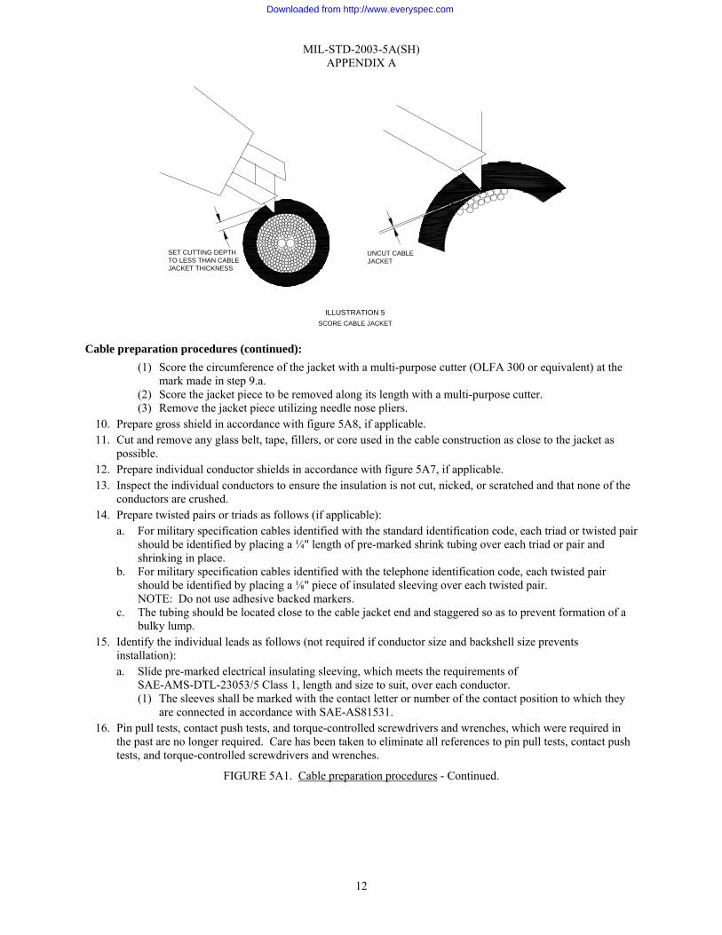
d. Remove the cable jacket to the predetermined length as follows: NOTE: Ensure the cut does not penetrate the jacket completely (illustration 5).
FIGURE 5A1. Cable preparation procedures - Continued.
ADJUSTABLECUTTING DEPTH
ILLUSTRATION 4CABLE STRIPPER
Downloaded from http://www.everyspec.com
MIL-STD-2003-5A(SH) APPENDIX A
12
Cable preparation procedures (continued): (1) Score the circumference of the jacket with a multi-purpose cutter (OLFA 300 or equivalent) at the
mark made in step 9.a. (2) Score the jacket piece to be removed along its length with a multi-purpose cutter. (3) Remove the jacket piece utilizing needle nose pliers.
10. Prepare gross shield in accordance with figure 5A8, if applicable. 11. Cut and remove any glass belt, tape, fillers, or core used in the cable construction as close to the jacket as
possible. 12. Prepare individual conductor shields in accordance with figure 5A7, if applicable. 13. Inspect the individual conductors to ensure the insulation is not cut, nicked, or scratched and that none of the
conductors are crushed. 14. Prepare twisted pairs or triads as follows (if applicable):
a. For military specification cables identified with the standard identification code, each triad or twisted pair should be identified by placing a ¼" length of pre-marked shrink tubing over each triad or pair and shrinking in place.
b. For military specification cables identified with the telephone identification code, each twisted pair should be identified by placing a ⅛" piece of insulated sleeving over each twisted pair. NOTE: Do not use adhesive backed markers.
c. The tubing should be located close to the cable jacket end and staggered so as to prevent formation of a bulky lump.
15. Identify the individual leads as follows (not required if conductor size and backshell size prevents installation): a. Slide pre-marked electrical insulating sleeving, which meets the requirements of
SAE-AMS-DTL-23053/5 Class 1, length and size to suit, over each conductor. (1) The sleeves shall be marked with the contact letter or number of the contact position to which they
are connected in accordance with SAE-AS81531. 16. Pin pull tests, contact push tests, and torque-controlled screwdrivers and wrenches, which were required in
the past are no longer required. Care has been taken to eliminate all references to pin pull tests, contact push tests, and torque-controlled screwdrivers and wrenches.
FIGURE 5A1. Cable preparation procedures - Continued.
ILLUSTRATION 5SCORE CABLE JACKET
SET CUTTING DEPTHTO LESS THAN CABLEJACKET THICKNESS
UNCUT CABLEJACKET
Downloaded from http://www.everyspec.com

MIL-STD-2003-5A(SH) APPENDIX A
13
Cable diameter build-up procedures: 1. These procedures shall be used when the cable entrance dimension of the backshell is too large for the cable
diameter to which the connector backshell assembly is being attached. 2. The material used for cable build-up must extend completely through the sealing grommet without
interruption at completion of connector assembly. 3. The first method depicts the use of heat shrink sleeving as the means to increase the cable diameter. The
second method depicts the use of telescoping bushings as the means of cable diameter build-up. Each method is designed such that it can be used individually or in combination with the other as the method for cable build-up.
4. The following method shall be used in conjunction with heat shrink sleeving.
a. Build up the cable jacket in the vicinity of the environmental seal and/or cable clamp as follows: (1) Measure the installed length of the grommet, grommet follower, and cable clamp. (2) Cut a correctly sized piece of heat shrinkable tubing meeting the requirements of
SAE-AMS-DTL-23053/5, Class 1 to a length equal to that measured in step 4.a(1). (a) The size of the heat shrink tubing shall be selected from table 5A2-I such that the inner diameter
after shrinkage shall be less than the cable diameter. FIGURE 5A2. Cable diameter build-up procedures.
TORQUE SCREWDRIVERCABLE
1/16" GAP MINIMUM
CLAMP BARS
CENTERING POST
ILLUSTRATION 1CABLE CLAMP GRIPPING
Downloaded from http://www.everyspec.com
MIL-STD-2003-5A(SH) APPENDIX A
14
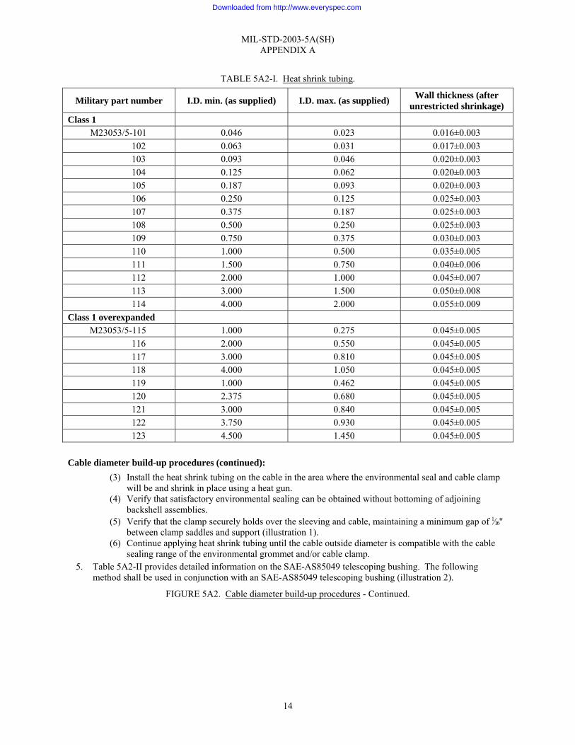
TABLE 5A2-I. Heat shrink tubing.
Military part number I.D. min. (as supplied) I.D. max. (as supplied) Wall thickness (after unrestricted shrinkage)
Class 1 M23053/5-101 0.046 0.023 0.016±0.003
102 0.063 0.031 0.017±0.003 103 0.093 0.046 0.020±0.003 104 0.125 0.062 0.020±0.003 105 0.187 0.093 0.020±0.003 106 0.250 0.125 0.025±0.003 107 0.375 0.187 0.025±0.003 108 0.500 0.250 0.025±0.003 109 0.750 0.375 0.030±0.003 110 1.000 0.500 0.035±0.005 111 1.500 0.750 0.040±0.006 112 2.000 1.000 0.045±0.007 113 3.000 1.500 0.050±0.008 114 4.000 2.000 0.055±0.009
Class 1 overexpanded M23053/5-115 1.000 0.275 0.045±0.005
116 2.000 0.550 0.045±0.005 117 3.000 0.810 0.045±0.005 118 4.000 1.050 0.045±0.005 119 1.000 0.462 0.045±0.005 120 2.375 0.680 0.045±0.005 121 3.000 0.840 0.045±0.005 122 3.750 0.930 0.045±0.005 123 4.500 1.450 0.045±0.005
Cable diameter build-up procedures (continued):
(3) Install the heat shrink tubing on the cable in the area where the environmental seal and cable clamp will be and shrink in place using a heat gun.
(4) Verify that satisfactory environmental sealing can be obtained without bottoming of adjoining backshell assemblies.
(5) Verify that the clamp securely holds over the sleeving and cable, maintaining a minimum gap of 1⁄16" between clamp saddles and support (illustration 1).
(6) Continue applying heat shrink tubing until the cable outside diameter is compatible with the cable sealing range of the environmental grommet and/or cable clamp.
5. Table 5A2-II provides detailed information on the SAE-AS85049 telescoping bushing. The following method shall be used in conjunction with an SAE-AS85049 telescoping bushing (illustration 2).
FIGURE 5A2. Cable diameter build-up procedures - Continued.
Downloaded from http://www.everyspec.com
MIL-STD-2003-5A(SH) APPENDIX A
15
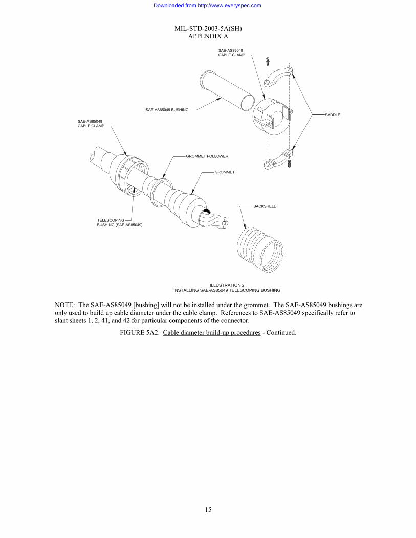
NOTE: The SAE-AS85049 [bushing] will not be installed under the grommet. The SAE-AS85049 bushings are only used to build up cable diameter under the cable clamp. References to SAE-AS85049 specifically refer to slant sheets 1, 2, 41, and 42 for particular components of the connector.
FIGURE 5A2. Cable diameter build-up procedures - Continued.
BACKSHELL
SADDLE
SAE-AS85049CABLE CLAMP
SAE-AS85049 BUSHING
SAE-AS85049CABLE CLAMP
GROMMET FOLLOWER
GROMMET
TELESCOPINGBUSHING (SAE-AS85049)
ILLUSTRATION 2INSTALLING SAE-AS85049 TELESCOPING BUSHING
Downloaded from http://www.everyspec.com

MIL-STD-2003-5A(SH) APPENDIX A
16
TABLE 5A2-II. Telescoping bushings.
SAE-AS85049 dash number A diameter B diameter C diameter D length
-3 0.130 0.210 0.379 2.875 -4 0.220 0.302 0.505 2.750 -6 0.312 0.427 0.619 2.625 -8 0.437 0.552 0.744 2.500
-10 0.562 0.615 0.889 2.375 -12 0.625 0.740 1.084 2.250 -16 0.750 0.927 1.314 2.125 -20 0.937 1.240 1.598 2.000 -24 1.250 1.365 1.847 1.875 -28 1.375 1.614 2.085 1.750 -32 1.624 1.864 2.335 1.625 -40 1.874 2.364 2.835 1.500
Cable diameter build-up procedures (continued):
a. Measure the installed length of the grommet, grommet follower, and cable clamp. If measured length is longer than available bushing, use heat shrink tubing to build up cable diameter.
b. Slide a correctly sized SAE-AS85049 telescoping bushing (illustration 3) on the conductor bundle.
(1) Table 5A2-II provides information on the SAE-AS85049 telescoping bushing in order to select the proper size based on the cable diameter.
FIGURE 5A2. Cable diameter build-up procedures - Continued.
C
D0.062"0.016±0.002"
B
A
ILLUSTRATION 3SAE-AS85049
Downloaded from http://www.everyspec.com

MIL-STD-2003-5A(SH) APPENDIX A
17
Cable diameter build-up procedures (continued): (2) Verify that satisfactory environmental sealing can be obtained without bottoming of adjoining
backshell assemblies. (3) Verify that the cable clamp securely holds over the bushing and cable maintaining a minimum gap of
1⁄16" between clamp saddles and support (illustration 1). NOTE: More than one bushing may be used to achieve the desired cable diameter (see illustration 5). NOTE: Two design bushings are available. The one has an outside end flange (illustration 3) while the other has no flange (illustration 4).
FIGURE 5A2. Cable diameter build-up procedures - Continued.
CABLE CLAMP
FIRST TELESCOPINGBUSHING
CABLE
SECOND TELESCOPINGBUSHING
ILLUSTRATION 5USING MORE THAN ONE TELESCOPING BUSHING
ØA
B
2.000±0.031"
ILLUSTRATION 4SAE-AS85049 BUSHING
Downloaded from http://www.everyspec.com

MIL-STD-2003-5A(SH) APPENDIX A
18
Individual lead stripping techniques: 1. Thermal stripping is the preferred method when compatible with the insulation type. 2. Observe the following precautions when stripping wires with either thermal or mechanical strippers:
a. Ensure the blades or heated stripping elements of thermal strippers are kept clean at all times. b. Ensure all stripping blades are sharp and free from nicks, dents, and any other mechanical deformities
that may prevent proper operation. c. Ensure the correct stripping hole is used for the corresponding wire size. Illustration 8 of figure 5A3 is
provided to show construction of a common conductor. CAUTION: There are significant differences between Navy and commercial (AWG) wire gauges. Ensure all comparisons are taken using the same convention.
d. When stripping the lead, hold the wire perpendicular to the cutting or thermal blade (see illustration 2 and illustration 7 on figure 5A3, for examples).
e. Avoid nicking, cutting, or otherwise damaging the wire strands. f. Ensure there are no frayed or ragged edges after the insulation has been removed. g. Ensure all insulation has been removed from the stripped area. h. Conductor strands may be re-twisted if required to restore the natural lay and tightness of the strands.
Avoid bare finger contact with the wire strands. 3. Glass braid or tape and synthetic rubber shall be removed utilizing precision mechanical strippers in
accordance with step 6. 4. Strip individual lead.
a. Strip lead using thermal or mechanical stripping method (step 5 or 6). Table 5A3-II on figures 5A3 contains conductor information for common Navy cables (MIL-DTL-24643) and the recommended stripping method. (For information on low smoke cables, refer to MIL-DTL-24643 and MIL-DTL-24640. For information on non-low smoke cable, refer to MIL-DTL-915.) (1) Strippers will be tested and adjusted on a test conductor prior to stripping actual cable conductor. (2) Avoid nicking, cutting, or damaging wire strands during stripping. (3) Take care to prevent small particles, especially those which are conductive, from entering into
connector contact cavities. Particles may hamper proper seating of contacts and cause short circuits. 5. Thermal stripper (illustration 1).
FIGURE 5A3. Individual lead stripping techniques.
PINCER TOOL
ILLUSTRATION 1THERMAL STRIPPER
SEE ILLUSTRATION 2
Downloaded from http://www.everyspec.com
MIL-STD-2003-5A(SH) APPENDIX A
19
Individual lead stripping techniques (continued): a. When required for personnel safety, an exhaust hood and fan ventilation system shall be used to exhaust
toxic fumes from polytetraflouroethylene or polyvinyl chloride. b. Observe the following when using thermal wire strippers:
(1) Determine the insulation material using table 5A3-II as guidance. (2) Employ the lowest temperature setting that will give satisfactory results. (3) Minimize the time heat is applied for stripping in order to minimize insulation damage and safety
hazards due to melting. At no time should the insulation decomposition temperature be utilized. (4) Assure the adequacy of exhaust ventilation.
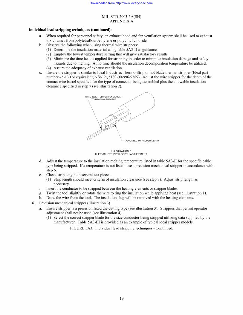
c. Ensure the stripper is similar to Ideal Industries Thermo-Strip or hot blade thermal stripper (Ideal part number 45-130 or equivalent; NSN 9Q5130-00-996-9389). Adjust the wire stripper for the depth of the contact wire barrel specified for the type of connector being assembled plus the allowable insulation clearance specified in step 7 (see illustration 2).
d. Adjust the temperature to the insulation melting temperature listed in table 5A3-II for the specific cable
type being stripped. If a temperature is not listed, use a precision mechanical stripper in accordance with step 6.
e. Check strip length on several test pieces. (1) Strip length should meet criteria of insulation clearance (see step 7). Adjust strip length as
necessary. f. Insert the conductor to be stripped between the heating elements or stripper blades. g. Twist the tool slightly or rotate the wire to ring the insulation while applying heat (see illustration 1). h. Draw the wire from the tool. The insulation slug will be removed with the heating elements.
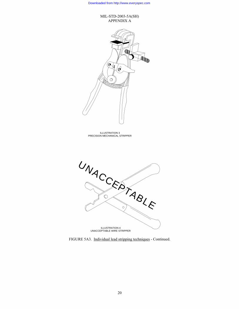
6. Precision mechanical stripper (illustration 3). a. Ensure stripper is a precision fixed die cutting type (see illustration 3). Strippers that permit operator
adjustment shall not be used (see illustration 4). (1) Select the correct stripper blade for the size conductor being stripped utilizing data supplied by the
manufacturer. Table 5A3-III is provided as an example of typical ideal stripper models. FIGURE 5A3. Individual lead stripping techniques - Continued.
ILLUSTRATION 2THERMAL STRIPPER DEPTH ADJUSTMENT
ADJUSTED TO PROPER DEPTH
WIRE INSERTED PERPENDICULARTO HEATING ELEMENT
Downloaded from http://www.everyspec.com
MIL-STD-2003-5A(SH) APPENDIX A
20
FIGURE 5A3. Individual lead stripping techniques - Continued.
ILLUSTRATION 3PRECISION MECHANICAL STRIPPER
ILLUSTRATION 4UNACCEPTABLE WIRE STRIPPER
UNACCEPTABLE
Downloaded from http://www.everyspec.com

MIL-STD-2003-5A(SH) APPENDIX A
21
Individual lead stripping techniques (continued): b. Examine the stripper to ensure the blades line up for proper operation (see illustration 5).
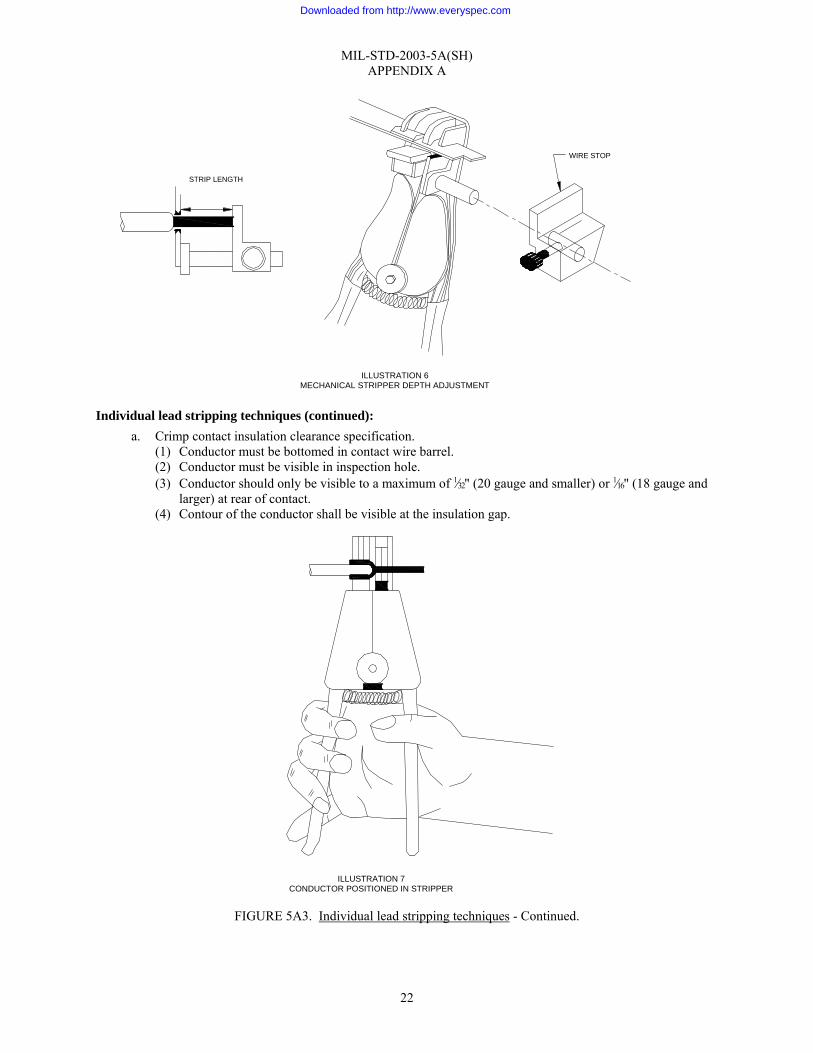
c. Set the wire stop for the depth of the contact wire barrel as specified in the connector assembly procedure
for the connector type being assembled, plus the allowable insulation clearance specified in step 7 (see illustration 6).
d. Check strip length on several test pieces. (1) Strip length shall meet the criteria of insulation clearance (see step 7). Adjust strip length as
necessary. (2) Ensure correct stripping hole is used for corresponding conductor gauge. See table 5A3-II for
conductor size. e. Position the conductor in the stripper jaws (see illustration 7). f. Squeeze the handles.
7. Examine the stripped wire for insulation damage and proper insulation clearance. Wires with damaged insulation shall not be used.
FIGURE 5A3. Individual lead stripping techniques - Continued.
ILLUSTRATION 5STRIPPING BLADE ALIGNMENT
26 24 22222426
IMPROPER ALIGNMENT PROPER ALIGNMENT
Downloaded from http://www.everyspec.com
MIL-STD-2003-5A(SH) APPENDIX A
22
Individual lead stripping techniques (continued): a. Crimp contact insulation clearance specification.
(1) Conductor must be bottomed in contact wire barrel. (2) Conductor must be visible in inspection hole. (3) Conductor should only be visible to a maximum of 1⁄32" (20 gauge and smaller) or 1⁄16" (18 gauge and
larger) at rear of contact. (4) Contour of the conductor shall be visible at the insulation gap.
FIGURE 5A3. Individual lead stripping techniques - Continued.
ILLUSTRATION 7CONDUCTOR POSITIONED IN STRIPPER
WIRE STOP
ILLUSTRATION 6MECHANICAL STRIPPER DEPTH ADJUSTMENT
STRIP LENGTH
Downloaded from http://www.everyspec.com

MIL-STD-2003-5A(SH) APPENDIX A
23
Individual lead stripping techniques (continued): b. Solder contact insulation clearance specification.
(1) Conductor must be bottomed in contact wire barrel. (2) Minimum clearance: Insulation must not be imbedded in the solder joint. (3) Contour of the conductor shall be visible at the insulation gap. (4) Maximum clearance: Less than two wire diameters including insulation or 1⁄16", whichever is larger,
but shall not permit shorting between adjacent conductors. 8. Examine the wire with a magnifying glass (6X to 10X power) to ensure the strands have not been scratched,
nicked, cut, scraped, broken, or otherwise damaged. a. See table 5A3-I for rejection criteria for solder contacts.
TABLE 5A3-I. Rejection criteria for solder contacts.
Number of strands Maximum allowable nicked or broken strands
Less than 7 0 7-15 1
16-18 2 19-25 3 26-36 4 37-40 5
41 or more 6
b. For crimped contacts, no conductor strand damage is acceptable.
9. Rework rejected conductors as follows:
a. Cut the conductor square where the damage ends. b. Re-strip the conductor in accordance with step 4.
FIGURE 5A3. Individual lead stripping techniques - Continued.
ILLUSTRATION 8TYPICAL CONDUCTOR CONSTRUCTION
(SEE TABLE 5A3-II)
CONDUCTOR INSULATION JACKET
(NOT ON ALL CONDUCTORS - SEE TABLE5A3-II)
CONDUCTOR INSULATION
COPPER CONDUCTOR
Downloaded from http://www.everyspec.com

MIL-STD-2003-5A(SH) APPENDIX A
24
TABLE 5A3-II. MIL-DTL-24643 cable.
Cab
le ty
pe
Con
duct
or
wir
e m
ater
ial
Size
of w
ire
cond
ucto
r
No.
of s
tran
ds
per
cond
ucto
r
Max
. wir
e di
amet
er
Max
. co
nduc
tor
diam
eter
Con
duct
or
prim
ary
insu
latio
n m
ater
ial
Insu
latio
n m
eltin
g te
mp.
Insu
latio
n de
com
posi
tion
tem
p.
Con
duct
or
insu
latio
n ja
cket
mat
eria
l
Insu
latio
n ja
cket
mel
ting
tem
p.
Insu
latio
n ja
cket
de
com
posi
tion
tem
p.
Rec
omm
ende
d st
ripp
ing
met
hod
LSDHOF-3 Copper, uncoated
2½(26) (Navy
standard) 26 0.061 0.123 Separator 1/
Temp. undetermined
1/
Temp. undetermined 1/
Synthetic rubber 248 °F 248 °F Mechanical
LSDHOF-4 Copper, uncoated 4(41) 41 0.077 0.139 Separator 1/
Temp. undetermined
1/
Temp. undetermined 1/
Synthetic rubber 248 °F 248 °F Mechanical
LSDHOF-6 Copper, uncoated
6(65) (Navy
standard) 65 0.097 0.159 Separator 1/
Temp. undetermined
1/
Temp. undetermined 1/
Synthetic rubber 248 °F 248 °F Mechanical
LSDSGU 3 Copper, uncoated
3(7) (Navy standard) 7 0.060 0.130
Extruded silicone rubber
482 °F 530 °F Glass braid 1300 °F -- Mechanical
LSDSGU-4 Copper, uncoated
4(7) (Navy standard) 7 0.076 0.143
Extruded silicone rubber
482 °F 530 °F Glass braid 1300 °F -- Mechanical
LSDSGU-50 Copper, uncoated
50(19) (Navy
standard) 19 0.254 0.334 Silicone
rubber 482 °F 530 °F Glass tape 1300 °F -- Mechanical
LSFHOF-4 Copper, uncoated
4(41) (Navy
standard) 41 0.077 0.139 Separator 1/
Temp. undetermined
1/
Temp. undetermined
Synthetic rubber 248 °F 248 °F Mechanical
LSFHOF-9 Copper, uncoated
9(90) (Navy
standard) 90 0.120 0.182 Separator 1/
Temp. undetermined
1/
Temp. undetermined 1/
Synthetic rubber 248 °F 248 °F Mechanical
LSFSGU-3 Copper, uncoated
3(7) (Navy standard) 7 0.060 0.096
Extruded silicone rubber
482 °F 530 °F Glass braid 1300 °F -- Mechanical
LSFSGU-4 Copper, uncoated
4(7) (Navy standard) 7 0.076 0.112
Extruded silicone rubber
482 °F 530 °F Glass braid 1300 °F -- Mechanical
LSFSGU-9 Copper, uncoated
9(7) (Navy standard) 7 0.108 0.154
Extruded silicone rubber
482 °F 530 °F Glass braid 1300 °F -- Mechanical
LSFSGU-23 Copper, uncoated
23(7) (Navy
standard) 7 0.171 0.316
Extruded silicone rubber
482 °F 530 °F Glass braid 1300 °F -- Mechanical
LSFSGU-50 Copper, uncoated
50(19) (Navy
standard) 19 0.254 0.334 Silicone
rubber 482 °F 530 °F Glass tape 1300 °F -- Mechanical
LSMCOS-2 Copper, uncoated
1½(16) (Navy
standard) 16 0.049 0.072 Separator Undetermined Undetermined
Cross linked polyethylene or synthetic
rubber
-- -- Mechanical
LSMCOS-6 Copper, uncoated
1(10) (Navy
standard) 10 0.038 0.064 Separator Undetermined Undetermined
Cross linked polyethylene or synthetic
rubber
-- -- Mechanical
LSTTOP-XX Copper, uncoated
1(10) (Navy
standard) 10 0.038 0.078 Separator Undetermined Undetermined
Cross linked polyethylene or synthetic
rubber
-- -- Mechanical
LSTTRS-XX Copper, uncoated
1(7) (Navy standard) 7 0.038 0.078 Separator Undetermined Undetermined
Cross linked polyethylene or synthetic
rubber
-- -- Mechanical
FIGURE 5A3. Individual lead stripping techniques - Continued.
Downloaded from http://www.everyspec.com
MIL-STD-2003-5A(SH) APPENDIX A
25
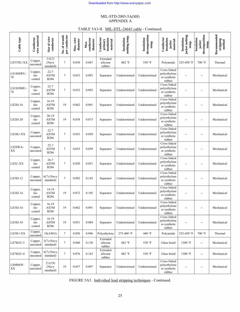
TABLE 5A3-II. MIL-DTL-24643 cable - Continued.
Cab
le ty
pe
Con
duct
or
wir
e m
ater
ial
Size
of w
ire
cond
ucto
r
No.
of s
tran
ds
per
cond
ucto
r
Max
. wir
e di
amet
er
Max
. co
nduc
tor
diam
eter
Con
duct
or
prim
ary
insu
latio
n m
ater
ial
Insu
latio
n m
eltin
g te
mp.
Insu
latio
n de
com
posi
tion
tem
p.
Con
duct
or
insu
latio
n ja
cket
m
ater
ial
Insu
latio
n ja
cket
mel
ting
tem
p.
Insu
latio
n ja
cket
de
com
posi
tion
tem
p.
Rec
omm
ende
d st
ripp
ing
met
hod
LSTTSU-XX Copper, uncoated
3/5(7) (Navy
standard) 7 0.030 0.047
Extruded silicone rubber
482 °F 530 °F Polyamide 325-450 °F 700 °F Thermal
LS1SMWU-70
Copper, tin-
coated
22-7 ASTM B286
7 0.033 0.093 Separator Undetermined Undetermined
Cross linked polyethylene or synthetic
rubber
-- -- Mechanical
LS1S50MU-70
Copper, tin-
coated
22-7 ASTM B286
7 0.033 0.093 Separator Undetermined Undetermined
Cross linked polyethylene or synthetic
rubber
-- -- Mechanical
LS2SJ-16 Copper,
tin-coated
16-19 ASTM B286
19 0.062 0.091 Separator Undetermined Undetermined
Cross linked polyethylene or synthetic
rubber
-- -- Mechanical
LS2SJ-20 Copper,
tin-coated
20-19 ASTM B286
19 0.038 0.073 Separator Undetermined Undetermined
Cross linked polyethylene or synthetic
rubber
-- -- Mechanical
LS2SU-XX Copper, uncoated
22-7 ASTM B286
7 0.033 0.059 Separator Undetermined Undetermined
Cross linked polyethylene or synthetic
rubber
-- -- Mechanical
LS2SWA-XX
Copper, uncoated
22-7 ASTM B286
7 0.033 0.059 Separator Undetermined Undetermined
Cross linked polyethylene or synthetic
rubber
-- -- Mechanical
LS2U-XX Copper,
tin-coated
26-7 ASTM B286
7 0.020 0.051 Separator Undetermined Undetermined
Cross linked polyethylene or synthetic
rubber
-- -- Mechanical
LS3SJ-12 Copper, uncoated
6(7) (Navy standard) 7 0.092 0.145 Separator Undetermined Undetermined
Cross linked polyethylene or synthetic
rubber
-- -- Mechanical
LS3SJ-14 Copper,
tin-coated
14-19 ASTM B286
19 0.072 0.105 Separator Undetermined Undetermined
Cross linked polyethylene or synthetic
rubber
-- -- Mechanical
LS3SJ-16 Copper,
tin-coated
16-19 ASTM B286
19 0.062 0.091 Separator Undetermined Undetermined
Cross linked polyethylene or synthetic
rubber
-- -- Mechanical
LS3SJ-18 Copper,
tin-coated
18-19 ASTM B286
19 0.051 0.084 Separator Undetermined Undetermined
Cross linked polyethylene or synthetic
rubber
-- -- Mechanical
LS3SU-XX Copper, uncoated 18(AWG) 7 0.050 0.096 Polyethylene 275-400 °F 440 °F Polyamide 325-450 °F 700 °F Thermal
LS7SGU-3 Copper, uncoated
3(7) (Navy standard) 7 0.060 0.130
Extruded silicone rubber
482 °F 530 °F Glass braid 1300 °F -- Mechanical
LS7SGU-4 Copper, uncoated
4(7) (Navy standard) 7 0.076 0.143
Extruded silicone rubber
482 °F 530 °F Glass braid 1300 °F -- Mechanical
LSMHOF-XX
Copper, uncoated
2½(19) (Navy
standard) 19 0.057 0.097 Separator Undetermined Undetermined
Cross linked polyethylene or synthetic
rubber
-- -- Mechanical
FIGURE 5A3. Individual lead stripping techniques - Continued.
Downloaded from http://www.everyspec.com

MIL-STD-2003-5A(SH) APPENDIX A
26
TABLE 5A3-II. MIL-DTL-24643 cable - Continued.
Cab
le ty
pe
Con
duct
or
wir
e m
ater
ial
Size
of w
ire
cond
ucto
r
No.
of s
tran
ds
per
cond
ucto
r
Max
. wir
e di
amet
er
Max
. co
nduc
tor
diam
eter
Con
duct
or
prim
ary
insu
latio
n m
ater
ial
Insu
latio
n m
eltin
g te
mp.
Insu
latio
n de
com
posi
tion
tem
p.
Con
duct
or
insu
latio
n ja
cket
m
ater
ial
Insu
latio
n ja
cket
mel
ting
tem
p.
Insu
latio
n ja
cket
de
com
posi
tion
tem
p.
Rec
omm
ende
d st
ripp
ing
met
hod
LSMSCU-XX
Copper, uncoated
2(7) (Navy standard) 7 0.048 0.084
Extruded silicone rubber
482 °F 530 °F Glass braid 1300 °F -- Mechanical
LSRG-108A/U
Copper, tin-
coated 20 AWG 7 0.038 0.079 Polyethylene 275-400 °F 440 °F None -- -- Thermal
LSSHOF-3 Copper, uncoated
2½(65) (Navy
standard) 85 0.061 0.123 Separator 1/
Temp. undetermined
1/
Temp. undetermined 1/
Synthetic rubber 248 °F 248 °F Mechanical
LSSSGU-50 Copper, uncoated
50(19) (Navy
standard) 19 0.254 0.334 Silicone
rubber 482 °F 530 °F Glass tape 1300 °F -- Mechanical
LSTHOF-3 Copper, uncoated
2½(26) (Navy
standard) 26 0.061 0.123 Separator 1/
Temp. undetermined
1/
Temp. undetermined 1/
Synthetic rubber 248 °F 248 °F Mechanical
LSTHOF-9 Copper, uncoated
9(90) (Navy
standard) 90 0.120 0.182 Separator 1/
Temp. undetermined
1/
Temp. undetermined 1/
Synthetic rubber 248 °F 248 °F Mechanical
LSTHOF-14 Copper, uncoated
14(140) (Navy
standard) 140 0.145 0.225 Separator 1/
Temp. undetermined
1/
Temp. undetermined 1/
Synthetic rubber 248 °F 248 °F Mechanical
LSTSGU-3 Copper, uncoated
3(7) (Navy standard) 7 0.060 0.130
Extruded silicone rubber
482 °F 530 °F Glass braid 1300 °F -- Mechanical
LSTSGU-4 Copper, uncoated
4(7) (Navy standard) 7 0.143
Extruded silicone rubber
482 °F 530 °F Glass braid 1300 °F -- Mechanical
LSTSGU-9 Copper, uncoated
9(7) (Navy standard) 7 0.108 0.187
Extruded silicone rubber
482 °F 530 °F Glass braid 1300 °F -- Mechanical
LSTSGU-14 Copper, uncoated
14(7) (Navy
standard) 7 0.136 0.230
Extruded silicone rubber
482 °F 530 °F Glass braid 1300 °F -- Mechanical
LSTSGU-23 Copper, uncoated
23(7) (Navy
standard) 7 0.171 0.284
Extruded silicone rubber
482 °F 530 °F Glass braid 1300 °F -- Mechanical
LSTSGU-150
Copper, uncoated
150(61) (Navy
standard) 61 0.451 0.557 Silicone
rubber 482 °F 530 °F Glass tape 1300 °F -- Mechanical
NOTES:
1/ Several types of wires are manufactured with a layer between the conductor and the insulation jacket called the separator. The separator may consist of various materials, such as glass fibers, synthetic fibers, synthetic fiber tape, polyester tape, etc. Ensure the separator is removed along with the insulation.
2/ In most instances, when manufactured in the watertight version, the letter W is added to the cable designation. Specification sheets should be consulted for cable type and construction details.
FIGURE 5A3. Individual lead stripping techniques - Continued.
Downloaded from http://www.everyspec.com
MIL-STD-2003-5A(SH) APPENDIX A
27
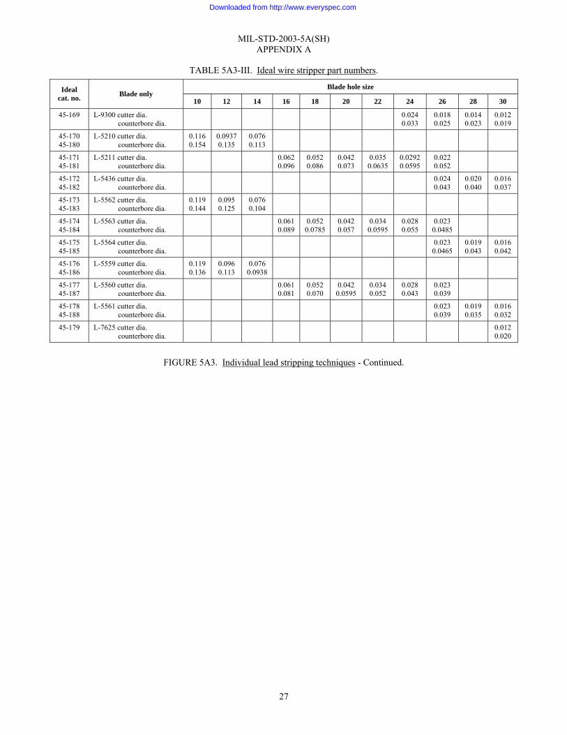
TABLE 5A3-III. Ideal wire stripper part numbers.
Blade hole size Ideal cat. no. Blade only
10 12 14 16 18 20 22 24 26 28 30
45-169 L-9300 cutter dia. counterbore dia.
0.024 0.033
0.018 0.025
0.0140.023
0.0120.019
45-170 45-180
L-5210 cutter dia. counterbore dia.
0.116 0.154
0.09370.135
0.0760.113
45-171 45-181
L-5211 cutter dia. counterbore dia.
0.0620.096
0.0520.086
0.042 0.073
0.035 0.0635
0.0292 0.0595
0.022 0.052
45-172 45-182
L-5436 cutter dia. counterbore dia.
0.024 0.043
0.0200.040
0.0160.037
45-173 45-183
L-5562 cutter dia. counterbore dia.
0.119 0.144
0.0950.125
0.0760.104
45-174 45-184
L-5563 cutter dia. counterbore dia.
0.0610.089
0.0520.0785
0.042 0.057
0.034 0.0595
0.028 0.055
0.023 0.0485
45-175 45-185
L-5564 cutter dia. counterbore dia.
0.023 0.0465
0.0190.043
0.0160.042
45-176 45-186
L-5559 cutter dia. counterbore dia.
0.119 0.136
0.0960.113
0.0760.0938
45-177 45-187
L-5560 cutter dia. counterbore dia.
0.0610.081
0.0520.070
0.042 0.0595
0.034 0.052
0.028 0.043
0.023 0.039
45-178 45-188
L-5561 cutter dia. counterbore dia.
0.023 0.039
0.0190.035
0.0160.032
45-179 L-7625 cutter dia. counterbore dia.
0.0120.020
FIGURE 5A3. Individual lead stripping techniques - Continued.
Downloaded from http://www.everyspec.com
MIL-STD-2003-5A(SH) APPENDIX A
28
Connector contact crimping techniques: 1. Observe the following when crimping contacts:
a. Ensure the crimping tool is calibrated in accordance with MIL-DTL-22520. b. The crimping tool and positioner shall conform to MIL-DTL-22520.
2. Select the crimping tool (see illustration 4) and positioner in accordance with those specified for the connector being assembled.
3. Check the crimping tool for proper operation as follows: a. Check proper action of tool.
(1) Squeeze handles together. (2) Check (ensure that) locking mechanism (ratchet) releases when handles are fully closed. (3) Release the handles.
b. Check proper action of crimpers. (1) Select correct inspection gauge (“GO”/”NO-GO” gauge) for crimping tool in accordance with
MIL-DTL-22520 or instruction sheet provided with crimping tool. (2) Rotate selector knob to correct position for testing in accordance with MIL-DTL-22520 or crimper
instruction sheet. (3) Activate the tool to the fully closed position and hold. The “GO” gauge shall be freely inserted in
the space between opposing closed indentors. Release pressure on the handles and allow the tool to open automatically.
(4) Activate the tool to the fully closed position and hold. The “NO-GO” gauge shall not be insertable between opposing indentors. NOTE: Do not crimp the gauge. It will damage the indentors.
4. Mount the positioner on the crimping tool in accordance with the appropriate instructions for the tool being used. NOTE: The tool handles must be fully open when inserting the positioner or changing the selector setting.
5. Set the wire size selector knob for the wire size being crimped. The correct wire size selector number is determined from the chart on the side of the turret head.
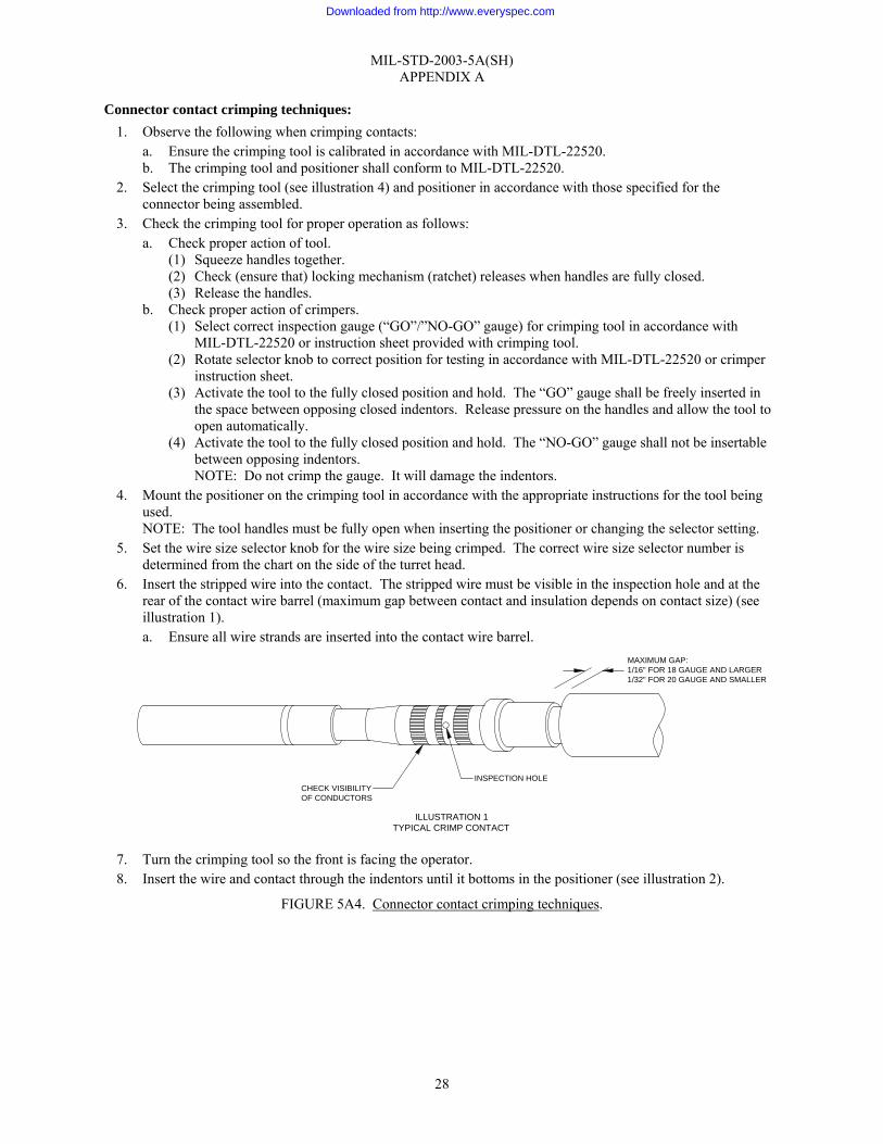
6. Insert the stripped wire into the contact. The stripped wire must be visible in the inspection hole and at the rear of the contact wire barrel (maximum gap between contact and insulation depends on contact size) (see illustration 1). a. Ensure all wire strands are inserted into the contact wire barrel.
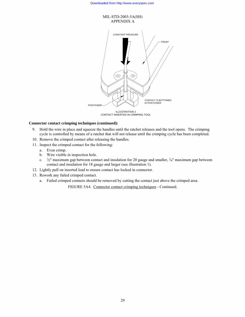
7. Turn the crimping tool so the front is facing the operator. 8. Insert the wire and contact through the indentors until it bottoms in the positioner (see illustration 2).
FIGURE 5A4. Connector contact crimping techniques.
ILLUSTRATION 1TYPICAL CRIMP CONTACT
INSPECTION HOLECHECK VISIBILITYOF CONDUCTORS
MAXIMUM GAP:1/16" FOR 18 GAUGE AND LARGER1/32" FOR 20 GAUGE AND SMALLER
Downloaded from http://www.everyspec.com
MIL-STD-2003-5A(SH) APPENDIX A
29
Connector contact crimping techniques (continued): 9. Hold the wire in place and squeeze the handles until the ratchet releases and the tool opens. The crimping
cycle is controlled by means of a ratchet that will not release until the crimping cycle has been completed. 10. Remove the crimped contact after releasing the handles. 11. Inspect the crimped contact for the following:
a. Even crimp. b. Wire visible in inspection hole. c. 1⁄32" maximum gap between contact and insulation for 20 gauge and smaller, 1⁄16" maximum gap between
contact and insulation for 18 gauge and larger (see illustration 1). 12. Lightly pull on inserted lead to ensure contact has locked in connector. 13. Rework any failed crimped contact.
a. Failed crimped contacts should be removed by cutting the contact just above the crimped area. FIGURE 5A4. Connector contact crimping techniques - Continued.
FRONT
POSITIONER
CONTACT IS BOTTOMEDIN POSITIONER
ILLUSTRATION 2CONTACT INSERTED IN CRIMPING TOOL
CONSTANT PRESSURE
Downloaded from http://www.everyspec.com

MIL-STD-2003-5A(SH) APPENDIX A
30
FIGURE 5A4. Connector contact crimping techniques - Continued.
ILLUSTRATION 4MIL-DTL-22520 CRIMPING TOOLS
Downloaded from http://www.everyspec.com

MIL-STD-2003-5A(SH) APPENDIX A
31
TABLE 5A4-I. Wire barrel size.
Axial load (pounds) Wire barrel size Wire size range Silver- or tin-plated
copper wire Nickel-plated copper wire Copper alloy wire
0000 25 25 0000
00 1/ 25 25 0 25 25
0 2 1/ 25 25 2 25 25
2 4 1/ 25 25 4 25 25
4 6 1/ 25 25 6 25 25
6 8 1/ 25 25 8 25 25
8 10 1/ 25 25 10 25 25
10 12 1/ 25 25 12 25 25
12 14 25 25 16 25 18.5
16 20 10 9.5 20 10 6.5 25
20 24 4 3 9 22 6 4 15
22 26 2.5 1.5 6 24 4 2.5 9
24 28 1.5 1.0 3.5 26 2.2 1.4 5.5
26 30 0.7 0.7 2 28 1.3 0.9 3.2
28 32 0.5 0.5 1.2
NOTE: 1/ With electrically conductive bushing.
FIGURE 5A4. Connector contact crimping techniques - Continued.
Downloaded from http://www.everyspec.com

MIL-STD-2003-5A(SH) APPENDIX A
32
Tinning techniques: 1. Observe the following prior to commencing work:
a. Solder Sn 60 or Sn 63 tin lead form W or B, type R, RMA, or S conforming to J-STD-006 shall be used for pre-tinning.
b. Only rosin flux shall be used in all soldering operations. Liquid rosin flux shall conform to J-STD-004, J-STD-005, and J-STD-006, as appropriate, type RMA, except that the copper mirror test is not required and the resistivity of the water extract shall be at least 45,000 ohm-centimeters.
c. Soldering guns will not be used and the use of a solder pot is not recommended. When conductors are tinned with a soldering iron, only ironclad tips shall be used. The following rules apply to soldering iron maintenance: (1) The soldering iron tip shall always be checked for full insertion into the heating element and tight
attachment to the iron. Oxidation scale shall not be allowed to accumulate between the heating element and the tip. The barrel of the cold iron shall be cleaned with a soft pipe cleaner or object when tip is removed, or once a week. A continuous tinned surface shall be maintained on the tip working-surface to ensure proper heat transfer and to avoid transfer of impurities to the solder connection.
(2) Plated tips shall be cleaned by scrubbing action on an alumina substrate (ceramic) while the iron is hot. Tin the tip by immersion in a ball of solder and flux until a bright shiny solder-coated surface is visible. Fine emery cloth may be substituted for ceramic substrate.
(3) Never file an ironclad soldering tip. (4) During use and just before each application, the heated and tinned soldering tip should be maintained
by passing the tip (with a rotary motion) through the folds of a damp cleaning sponge. This removes the surface dross from the working surface. Never shake or “whip” the iron to remove excess solder. Use Kimwipes® (or equivalent) or cloth diapers to remove excess solder.
2. Tinning with soldering iron (see illustration 1): a. Check the wire for adequate strip length (as required by figure 5A3) and for nicks, cut strands, or other
damage. If rejectable defects are evident, replace the wire; or if wire length is adequate, re-strip in accordance with figure 5A3.
b. The size of the soldering iron to be used should be determined from table 5A5-I based on the size of the wire being tinned.
TABLE 5A5-I. Soldering iron size.
Wire size (AWG)
Soldering element size – maximum wattage capacity
Maximum tip temperature
0 150 W 1000 °F 4 150 W 1000 °F 8 150 W 1000 °F
10 75 W 800 °F 12 60 W 800 °F 16 50 W 800 °F 20 35 W 800 °F 22 35 W 800 °F
24-26 24 W 800 °F
c. Select a soldering iron tip that will give the maximum “contact” to the connection. Illustration 1 shows representative tips and is not intended as a selection guide.
FIGURE 5A5. Tinning techniques.
Downloaded from http://www.everyspec.com

MIL-STD-2003-5A(SH) APPENDIX A
33
Tinning techniques (continued): d. Prepare the soldering iron with a solder heat bridge - pool of solder (illustration 2A). e. Place the stripped end of the conductor to be tinned on the iron tip in the pool of solder (illustration 2B). f. Apply rosin core solder to the wire (illustration 2C). g. Separate the wire from the iron with a wiping motion (illustration 2D).
NOTE: Do not permit solder to wick up under the insulation. An anti-wicking tool is recommended to prevent excessive wicking.
FIGURE 5A5. Tinning techniques - Continued.
POOL OF SOLDERFOR HEAT BRIDGE
POSITIONSOLDER ON WIRE
PLACE WIREIN HEAT BRIDGE
REMOVE WIREAS WICKING TAKES PLACE
ILLUSTRATION 2TINNING LEADS
2A2C
2B
2D
ILLUSTRATION 1SOLDERING IRON TIPS
PYRAMID
CHISELSHORT-TAPER
CHISELLONG-TAPER
SEMI-CHISELWIDE
SEMI-CHISELNARROW
BALL POINT
TURNED DOWN TIP
CONCAVE
CONICAL SHARP
CONICAL BLUNT
CONICAL BEVEL
CONICAL CHISEL
SCREW-TYPE TIP
ROUND BEVEL
FOR #8 AND LARGER
FOR MEDIUMCONTACTS
FOR SMALL CONTACTS
UNIFORM SHANK
BENT
SCREWDRIVER
Downloaded from http://www.everyspec.com
MIL-STD-2003-5A(SH) APPENDIX A
34
Tinning techniques (continued): h. Allow wire to cool. i. Inspect the tinned wire in accordance with step 3.
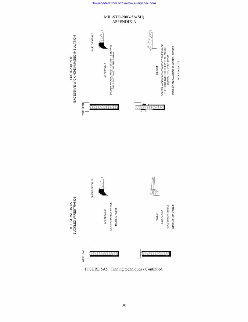
3. Inspect the tinned wire (illustrations 3 and 4) as follows: a. Visually check the tinned wire for complete wicking between strands, complete wetting, and visibility of
wire strands in the tinned area. b. Examine the tinned wire for evidence of rejectable defects.
(1) Rejectable defects include insufficient or excess solder, balled solder, fractured solder, pits, holes, voids, inclusions, granular appearance, charred insulation, or buckled wire strands.
FIGURE 5A5. Tinning techniques - Continued.
Downloaded from http://www.everyspec.com

MIL-STD-2003-5A(SH) APPENDIX A
35
FIGURE 5A5. Tinning techniques - Continued.
AC
CE
PTAB
LE
STR
AND
S P
ARTI
ALL
Y O
BS
CU
RED
FILL
ET
SUR
FAC
E IS
STR
AIG
HT,
NO
T C
ON
CAV
E
SH
IELD
PIG
TAIL
S
WIR
E L
EAD
ILLU
STR
ATI
ON
3A
EX
CE
SS
IVE
/BA
LLE
D S
OLD
ER
RE
JEC
T
SO
LDER
SP
LATT
ERS
FILL
ET
SUR
FAC
E IS
BA
LLED
UP,
NO
T S
TRA
IGH
T O
R C
ON
CAV
E
STR
AND
S N
OT
VIS
IBLE
AC
CE
PTA
BLE
STR
AND
S V
ISIB
LE U
ND
ER S
OLD
ER
SLI
GH
T B
ULG
ING
IN A
PP
EAR
AN
CE
SO
LDE
R F
EA
THE
RS
TO
BA
SE M
ETA
LSH
IELD
PIG
TAIL
S
WIR
E L
EAD
ILLU
STR
ATI
ON
3B
CO
LD S
OLD
ER
RE
JEC
T
BA
LLE
D S
OLD
ER D
OE
S N
OT
WE
T AL
L SU
RFA
CES
SO
LDE
R W
ETT
ING
IS N
OT
EVI
DE
NT
ON
ALL
SU
RFA
CE
S
SO
LDE
R S
UR
FAC
E IS
NO
T S
MO
OTH
AN
D C
ON
TIN
UO
US
Downloaded from http://www.everyspec.com
MIL-STD-2003-5A(SH) APPENDIX A
36
FIGURE 5A5. Tinning techniques - Continued.
AC
CE
PTAB
LE
WIC
KIN
G B
AR
ELY
VIS
IBLE
MIN
IMU
M F
ILLE
T
SH
IELD
PIG
TAIL
S
WIR
E L
EAD
ILLU
STR
ATI
ON
4A
BU
CK
LED
WIR
ES
TRA
ND
S
RE
JEC
T
BIR
DC
AGIN
G
SO
LDE
R N
OT
VIS
IBLE
WIC
KIN
G N
OT
VIS
IBLE
AC
CE
PTA
BLE
SO
LDE
R W
ICK
ING
MU
ST T
ERM
INA
TE B
EFO
RE
THE
TIG
HT
TWIS
T O
F TH
E P
IGTA
IL
SH
IELD
PIG
TAIL
S
WIR
E L
EAD
ILLU
STR
ATI
ON
4B
EX
CE
SS
IVE
WIC
KIN
G/D
AM
AG
ED
INS
ULA
TIO
N
RE
JEC
T
SOLD
ER
WIC
KIN
G C
ON
TIN
UE
S TO
TH
E E
ND
OF
THE
TIG
HT
TWIS
T O
F TH
E P
IGTA
IL A
ND
/OR
BEY
ON
D IN
TO O
PEN
BR
AID
INS
ULA
TIO
N D
AM
AG
ED
, CH
AR
RE
D, B
UR
NED
NIC
KS
AN
D C
UTS
Downloaded from http://www.everyspec.com
MIL-STD-2003-5A(SH) APPENDIX A
37
Connector contact soldering techniques: 1. Solder Sn 60 or Sn 63 tin lead Form W, Type R, or RMA conforming to J-STD-006 shall be used for
connector soldering. 2. Only rosin flux shall be used in all soldering operations. Liquid rosin flux shall conform to J-STD-004,
J-STD-005, and J-STD-006, as appropriate, Type RMA, except that the copper mirror test is not required, and the resistivity of the water extract shall be at least 45,000 ohm-centimeters.
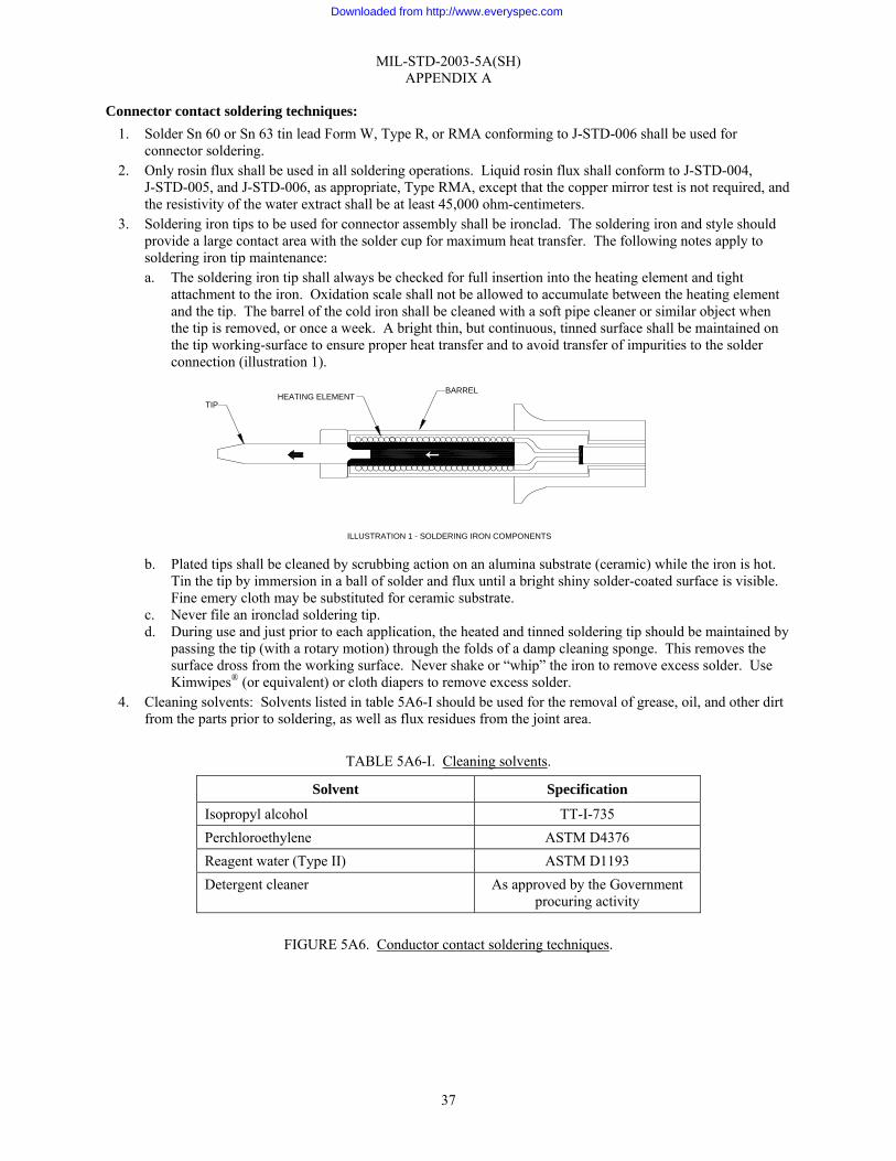
3. Soldering iron tips to be used for connector assembly shall be ironclad. The soldering iron and style should provide a large contact area with the solder cup for maximum heat transfer. The following notes apply to soldering iron tip maintenance: a. The soldering iron tip shall always be checked for full insertion into the heating element and tight
attachment to the iron. Oxidation scale shall not be allowed to accumulate between the heating element and the tip. The barrel of the cold iron shall be cleaned with a soft pipe cleaner or similar object when the tip is removed, or once a week. A bright thin, but continuous, tinned surface shall be maintained on the tip working-surface to ensure proper heat transfer and to avoid transfer of impurities to the solder connection (illustration 1).
b. Plated tips shall be cleaned by scrubbing action on an alumina substrate (ceramic) while the iron is hot.
Tin the tip by immersion in a ball of solder and flux until a bright shiny solder-coated surface is visible. Fine emery cloth may be substituted for ceramic substrate.
c. Never file an ironclad soldering tip. d. During use and just prior to each application, the heated and tinned soldering tip should be maintained by
passing the tip (with a rotary motion) through the folds of a damp cleaning sponge. This removes the surface dross from the working surface. Never shake or “whip” the iron to remove excess solder. Use Kimwipes® (or equivalent) or cloth diapers to remove excess solder.
4. Cleaning solvents: Solvents listed in table 5A6-I should be used for the removal of grease, oil, and other dirt from the parts prior to soldering, as well as flux residues from the joint area.
TABLE 5A6-I. Cleaning solvents.
Solvent Specification
Isopropyl alcohol TT-I-735 Perchloroethylene ASTM D4376 Reagent water (Type II) ASTM D1193 Detergent cleaner As approved by the Government
procuring activity
FIGURE 5A6. Conductor contact soldering techniques.
ILLUSTRATION 1 - SOLDERING IRON COMPONENTS
TIPHEATING ELEMENT
BARREL
Downloaded from http://www.everyspec.com
MIL-STD-2003-5A(SH) APPENDIX A
38
Connector contact soldering techniques (continued): 5. Method:
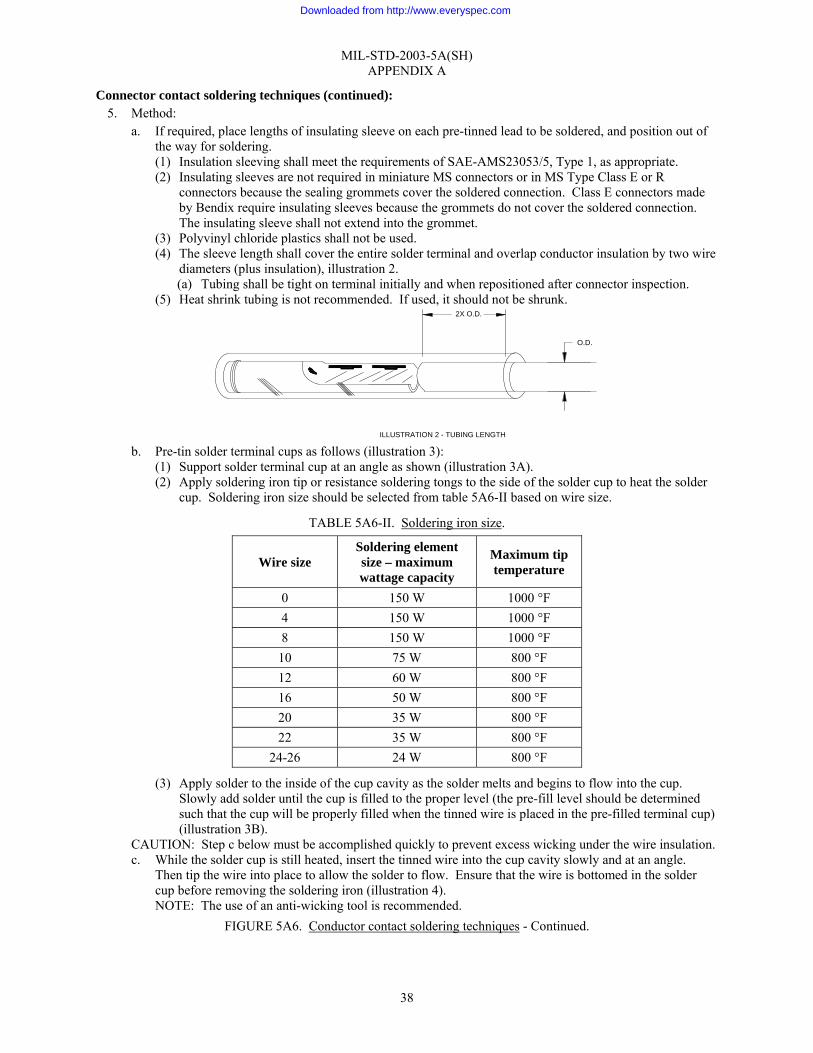
a. If required, place lengths of insulating sleeve on each pre-tinned lead to be soldered, and position out of the way for soldering. (1) Insulation sleeving shall meet the requirements of SAE-AMS23053/5, Type 1, as appropriate. (2) Insulating sleeves are not required in miniature MS connectors or in MS Type Class E or R
connectors because the sealing grommets cover the soldered connection. Class E connectors made by Bendix require insulating sleeves because the grommets do not cover the soldered connection. The insulating sleeve shall not extend into the grommet.
(3) Polyvinyl chloride plastics shall not be used. (4) The sleeve length shall cover the entire solder terminal and overlap conductor insulation by two wire
diameters (plus insulation), illustration 2. (a) Tubing shall be tight on terminal initially and when repositioned after connector inspection.
(5) Heat shrink tubing is not recommended. If used, it should not be shrunk.
b. Pre-tin solder terminal cups as follows (illustration 3):
(1) Support solder terminal cup at an angle as shown (illustration 3A). (2) Apply soldering iron tip or resistance soldering tongs to the side of the solder cup to heat the solder
cup. Soldering iron size should be selected from table 5A6-II based on wire size.
TABLE 5A6-II. Soldering iron size.
Wire size Soldering element size – maximum wattage capacity
Maximum tip temperature
0 150 W 1000 °F 4 150 W 1000 °F 8 150 W 1000 °F
10 75 W 800 °F 12 60 W 800 °F 16 50 W 800 °F 20 35 W 800 °F 22 35 W 800 °F
24-26 24 W 800 °F
(3) Apply solder to the inside of the cup cavity as the solder melts and begins to flow into the cup. Slowly add solder until the cup is filled to the proper level (the pre-fill level should be determined such that the cup will be properly filled when the tinned wire is placed in the pre-filled terminal cup) (illustration 3B).
CAUTION: Step c below must be accomplished quickly to prevent excess wicking under the wire insulation. c. While the solder cup is still heated, insert the tinned wire into the cup cavity slowly and at an angle.
Then tip the wire into place to allow the solder to flow. Ensure that the wire is bottomed in the solder cup before removing the soldering iron (illustration 4). NOTE: The use of an anti-wicking tool is recommended.
FIGURE 5A6. Conductor contact soldering techniques - Continued.
O.D.
2X O.D.
ILLUSTRATION 2 - TUBING LENGTH
Downloaded from http://www.everyspec.com

MIL-STD-2003-5A(SH) APPENDIX A
39
FIGURE 5A6. Conductor contact soldering techniques - Continued.
ILLUSTRATION 3ASOLDER CUP TERMINAL
AT 45° ANGLE
ILLUSTRATION 3BPREFILL SOLDER
TO PROPER LEVEL
ANGLE ALLOWS GASESAND RESIN TO ESCAPE
ILLUSTRATION 3CPRE-TINNING SOLDER TERMINAL
CUPS USING SOLDERLESS TONGS
ILLUSTRATION 3 - PRE-TINNING THE SOLDER TERMINAL CUPS
Downloaded from http://www.everyspec.com

MIL-STD-2003-5A(SH) APPENDIX A
40
Connector contact soldering techniques (continued):
d. Remove the soldering iron or resistance soldering tongs from the solder terminal cup. e. Support the wire without movement while the solder cools and solidifies. f. Clean the soldered connection with a non-metal fiber brush dampened in solvent (step 4). Remove all
traces of flux and solvent residues by blotting the area dry with an absorbent lint-free material. g. Alternate method: Pre-fill all solder cups (step 5.b), then proceed with installing wires (steps 5.c through
5.f). h. Visually inspect solder connection for compliance with the following criteria:
(1) Clean, smooth, bright, undisturbed surface with a concave fillet between all strands and from conductor to cup.
(2) Solder shall not wick under conductor insulation. (3) Insulation shall not be damaged or deformed. (4) Wire insulation shall not be imbedded in the solder joint. Maximum insulation clearance shall be
two wire diameters including insulation or 1⁄16", whichever is larger. (5) Examples of rejectable defects are shown in illustrations 5A-5J.
FIGURE 5A6. Conductor contact soldering techniques - Continued.
WHILE STILL HOT,BOTTOM WIREINTO CONTACT
CAREFULLY INSERT WIRE SOSOLDER DOES NOT SPILL OUT
ILLUSTRATION 4WIRE INSERTION IN CONTACT
Downloaded from http://www.everyspec.com
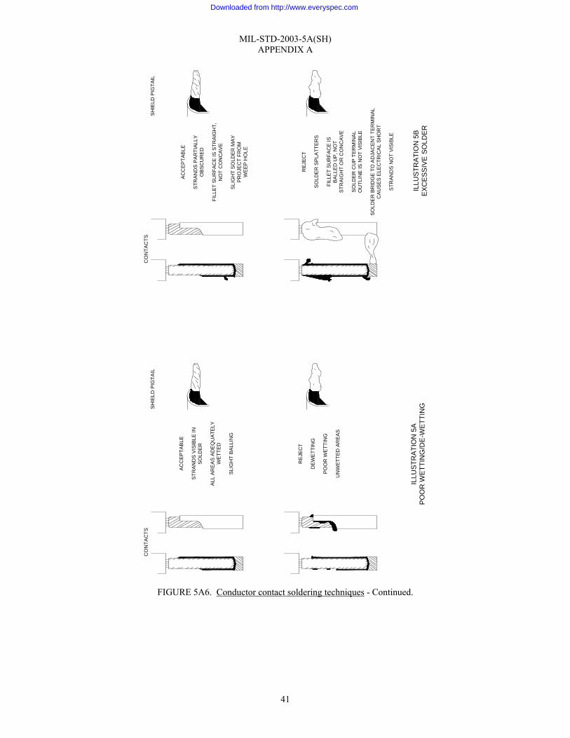
MIL-STD-2003-5A(SH) APPENDIX A
41
FIGURE 5A6. Conductor contact soldering techniques - Continued.
ILLU
STR
ATI
ON
5A
PO
OR
WET
TIN
G/D
E-W
ETTI
NG
AC
CEP
TAB
LE
STR
AND
S P
ARTI
ALLY
OB
SCU
RED
FILL
ET
SU
RFA
CE
IS S
TRA
IGH
T,N
OT
CO
NC
AVE
SLI
GH
T S
OLD
ER
MAY
PR
OJE
CT
FRO
MW
EEP
HO
LE
SH
IELD
PIG
TAIL
CO
NTA
CTS
REJ
ECT
SO
LDE
R S
PLA
TTER
S
FILL
ET
SU
RFA
CE
ISB
ALL
ED
UP
, NO
TS
TRA
IGH
T O
R C
ON
CAV
E
SO
LDER
CU
P TE
RM
INA
LO
UTL
INE
IS N
OT
VIS
IBLE
SO
LDE
R B
RID
GE
TO A
DJA
CE
NT
TER
MIN
ALC
AU
SES
ELE
CTR
ICA
L S
HO
RT
STR
AN
DS
NO
T VI
SIBL
E
ILLU
STR
ATI
ON
5B
EXC
ESS
IVE
SOLD
ER
AC
CEP
TAB
LE
STR
AN
DS
VIS
IBLE
INS
OLD
ER
ALL
AR
EA
S A
DE
QU
ATE
LYW
ETT
ED
SLI
GH
T BA
LLIN
G
SHIE
LD P
IGTA
ILC
ON
TAC
TS
RE
JEC
T
DEW
ETTI
NG
POO
R W
ETT
ING
UN
WET
TED
AR
EAS
Downloaded from http://www.everyspec.com
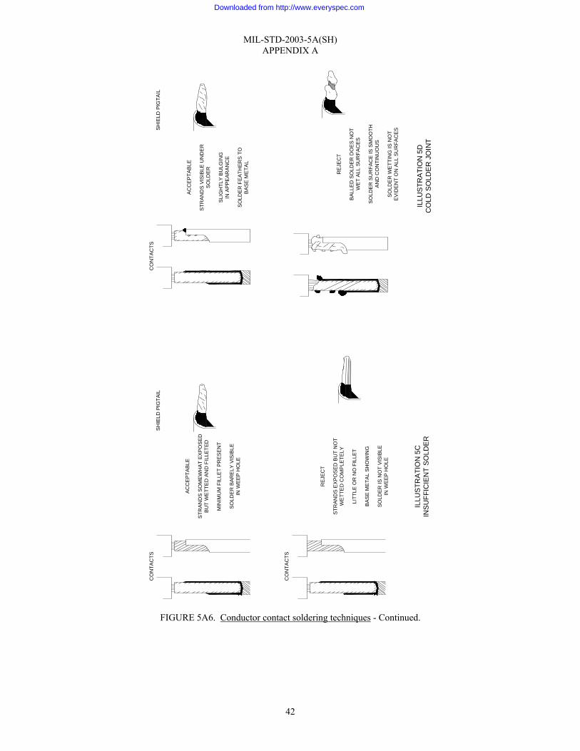
MIL-STD-2003-5A(SH) APPENDIX A
42
FIGURE 5A6. Conductor contact soldering techniques - Continued.
ILLU
STR
ATI
ON
5D
CO
LD S
OLD
ER J
OIN
T
REJ
ECT
STR
AND
S E
XPO
SED
BU
T N
OT
WE
TTE
D C
OM
PLE
TELY
LITT
LE O
R N
O F
ILLE
T
BA
SE
ME
TAL
SHO
WIN
G
SOLD
ER
IS N
OT
VIS
IBLE
IN W
EEP
HO
LE
CO
NTA
CTS
RE
JEC
T
BAL
LED
SO
LDER
DO
ES
NO
TW
ET A
LL S
UR
FAC
ES
SO
LDE
R S
UR
FAC
E IS
SM
OO
THA
ND
CO
NTI
NU
OU
S
SO
LDE
R W
ETT
ING
IS N
OT
EV
IDE
NT
ON
ALL
SU
RFA
CES
AC
CE
PTA
BLE
STR
AN
DS
SO
ME
WH
AT
EXP
OSE
DB
UT
WE
TTE
D A
ND
FIL
LETE
D
MIN
IMU
M F
ILLE
T P
RES
EN
T
SO
LDE
R B
AR
ELY
VIS
IBLE
IN W
EEP
HO
LE
SH
IELD
PIG
TAIL
CO
NTA
CTS
ILLU
STR
ATI
ON
5C
INS
UFF
ICIE
NT
SO
LDE
R
AC
CEP
TAB
LE
STR
AN
DS
VIS
IBLE
UN
DER
SO
LDER
SLI
GH
TLY
BU
LGIN
GIN
AP
PE
ARA
NC
E
SO
LDE
R F
EAT
HER
S T
OB
AS
E M
ETA
L
SHIE
LD P
IGTA
ILC
ON
TAC
TS
Downloaded from http://www.everyspec.com
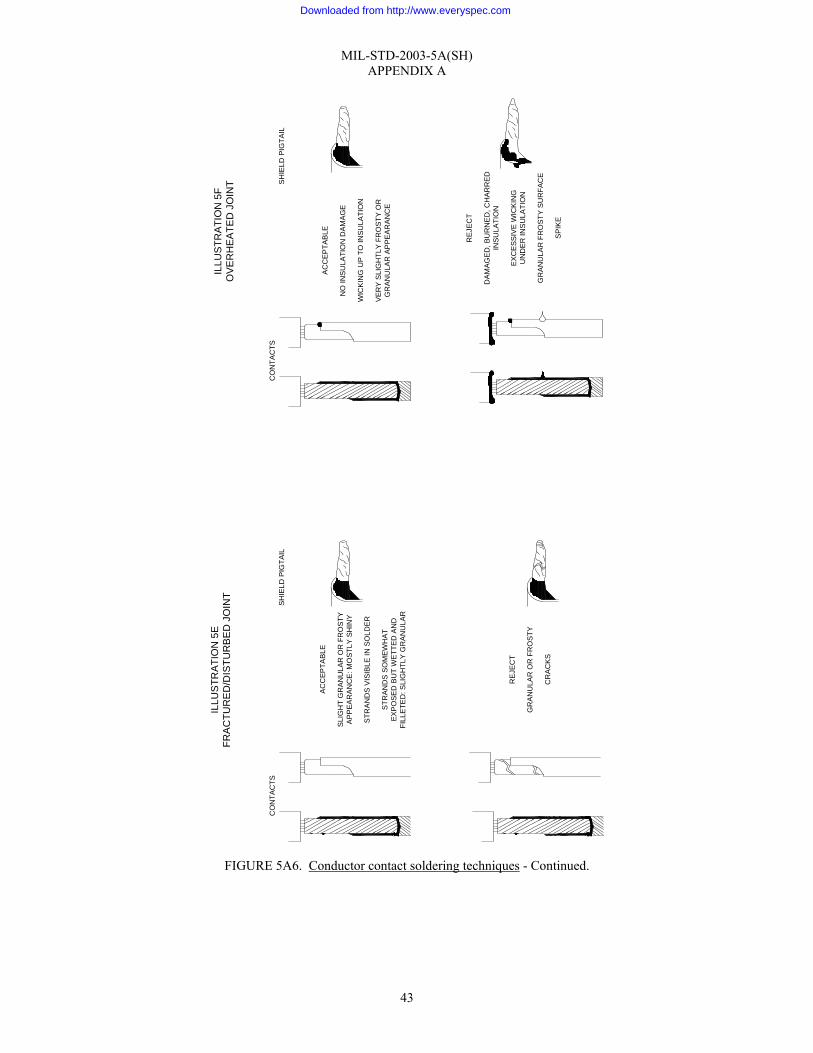
MIL-STD-2003-5A(SH) APPENDIX A
43
FIGURE 5A6. Conductor contact soldering techniques - Continued.
AC
CEP
TAB
LE
SLI
GH
T G
RAN
ULA
R O
R F
RO
STY
AP
PEA
RA
NC
E: M
OST
LY S
HIN
Y
STR
AN
DS
VIS
IBLE
IN S
OLD
ER
STR
AND
S S
OM
EWH
ATE
XPO
SE
D B
UT
WET
TED
AN
DFI
LLE
TED
: SLI
GH
TLY
GR
AN
ULA
R
SHIE
LD P
IGTA
ILC
ON
TAC
TS
ILLU
STR
ATI
ON
5E
FRA
CTU
RE
D/D
ISTU
RB
ED
JO
INT
AC
CEP
TAB
LE
NO
INS
ULA
TIO
N D
AMA
GE
WIC
KIN
G U
P T
O IN
SULA
TIO
N
VER
Y S
LIG
HTL
Y F
RO
STY
OR
GR
ANU
LAR
AP
PEA
RAN
CE
SHIE
LD P
IGTA
ILC
ON
TAC
TS
ILLU
STR
ATI
ON
5F
OVE
RH
EATE
D J
OIN
T
RE
JEC
T
GR
AN
ULA
R O
R F
RO
STY
CR
AC
KS
RE
JEC
T
DAM
AGE
D, B
UR
NE
D, C
HAR
RE
DIN
SU
LATI
ON
EX
CE
SSIV
E W
ICK
ING
UN
DE
R IN
SU
LATI
ON
GR
AN
ULA
R F
RO
STY
SU
RFA
CE
SP
IKE
Downloaded from http://www.everyspec.com
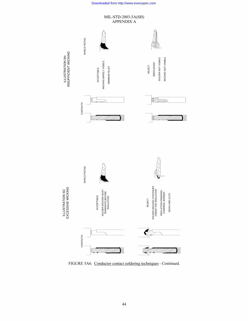
MIL-STD-2003-5A(SH) APPENDIX A
44
FIGURE 5A6. Conductor contact soldering techniques - Continued.
AC
CEP
TAB
LE
SOLD
ER
WIC
KIN
G M
US
TTE
RM
INA
TE B
EFO
RE
INS
ULA
TIO
N
SHIE
LD P
IGTA
ILC
ON
TAC
TS
ILLU
STR
ATI
ON
5G
EXC
ESSI
VE W
ICKI
NG
AC
CEP
TAB
LE
WIC
KIN
G B
AR
ELY
VIS
IBLE
MIN
IMU
M F
ILLE
T
SHIE
LD P
IGTA
ILC
ON
TAC
TS
ILLU
STR
ATI
ON
5H
INS
UFF
ICIE
NT
WIC
KIN
G
RE
JEC
T
SO
LDE
R W
ICK
ING
CO
NTI
NU
ESU
ND
ER T
HE
INS
ULA
TIO
N
INS
ULA
TIO
N D
AMA
GED
,C
HA
RR
ED
, BU
RN
ED
NIC
KS
AN
D C
UTS
REJ
EC
T
BIR
DC
AGIN
G
SO
LDE
R N
OT
VISI
BLE
WIC
KIN
G N
OT
VIS
IBLE
Downloaded from http://www.everyspec.com
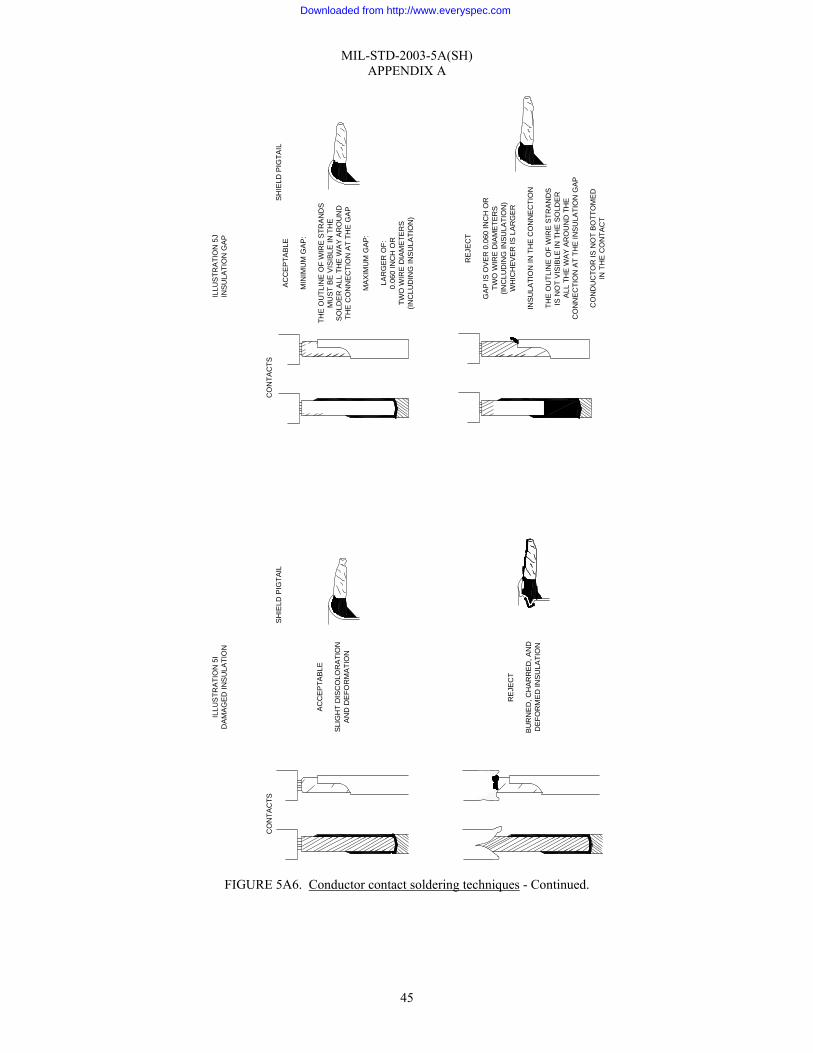
MIL-STD-2003-5A(SH) APPENDIX A
45
FIGURE 5A6. Conductor contact soldering techniques - Continued.
ILLU
STR
ATI
ON
5I
DA
MA
GE
D IN
SU
LATI
ON
ILLU
STR
ATI
ON
5J
INS
ULA
TIO
N G
AP
AC
CE
PTA
BLE
SLI
GH
T D
ISC
OLO
RA
TIO
NA
ND
DE
FOR
MA
TIO
N
SH
IELD
PIG
TAIL
CO
NTA
CTS
AC
CE
PTA
BLE
MIN
IMU
M G
AP
:
THE
OU
TLIN
E O
F W
IRE
STR
AN
DS
MU
ST
BE
VIS
IBLE
IN T
HE
SO
LDE
R A
LL T
HE
WA
Y A
RO
UN
DTH
E C
ON
NE
CTI
ON
AT
THE
GA
P
MA
XIM
UM
GA
P:
LAR
GE
R O
F:0.
060
INC
H O
RTW
O W
IRE
DIA
ME
TER
S(IN
CLU
DIN
G IN
SU
LATI
ON
)
SH
IELD
PIG
TAIL
CO
NTA
CTS
RE
JEC
T
BU
RN
ED
, CH
AR
RE
D, A
ND
DE
FOR
ME
D IN
SU
LATI
ON
RE
JEC
T
GA
P IS
OV
ER
0.0
60 IN
CH
OR
TWO
WIR
E D
IAM
ETE
RS
(INC
LUD
ING
INS
ULA
TIO
N)
WH
ICH
EV
ER
IS L
AR
GE
R
INS
ULA
TIO
N IN
TH
E C
ON
NE
CTI
ON
THE
OU
TLIN
E O
F W
IRE
STR
AN
DS
IS N
OT
VIS
IBLE
IN T
HE
SO
LDE
RA
LL T
HE
WA
Y A
RO
UN
D T
HE
CO
NN
EC
TIO
N A
T TH
E IN
SU
LATI
ON
GA
P
CO
ND
UC
TOR
IS N
OT
BO
TTO
ME
DIN
TH
E C
ON
TAC
T
Downloaded from http://www.everyspec.com
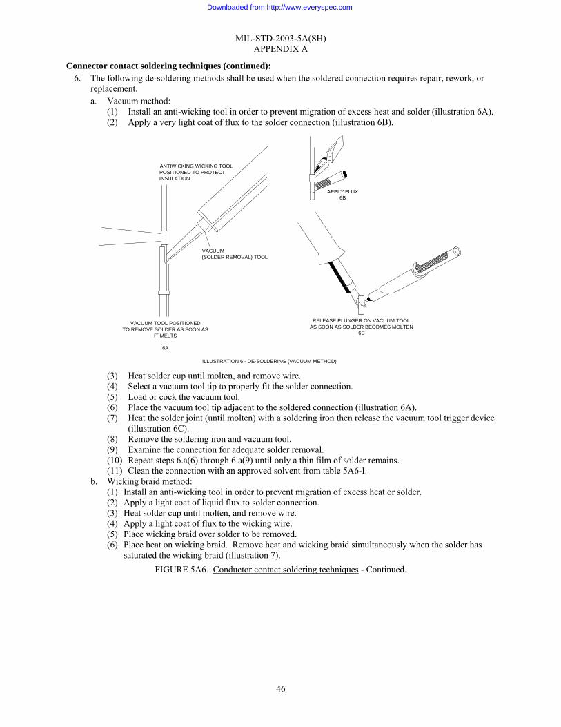
MIL-STD-2003-5A(SH) APPENDIX A
46
Connector contact soldering techniques (continued): 6. The following de-soldering methods shall be used when the soldered connection requires repair, rework, or
replacement. a. Vacuum method:
(1) Install an anti-wicking tool in order to prevent migration of excess heat and solder (illustration 6A). (2) Apply a very light coat of flux to the solder connection (illustration 6B).
(3) Heat solder cup until molten, and remove wire. (4) Select a vacuum tool tip to properly fit the solder connection. (5) Load or cock the vacuum tool. (6) Place the vacuum tool tip adjacent to the soldered connection (illustration 6A). (7) Heat the solder joint (until molten) with a soldering iron then release the vacuum tool trigger device
(illustration 6C). (8) Remove the soldering iron and vacuum tool. (9) Examine the connection for adequate solder removal. (10) Repeat steps 6.a(6) through 6.a(9) until only a thin film of solder remains. (11) Clean the connection with an approved solvent from table 5A6-I.
b. Wicking braid method: (1) Install an anti-wicking tool in order to prevent migration of excess heat or solder. (2) Apply a light coat of liquid flux to solder connection. (3) Heat solder cup until molten, and remove wire. (4) Apply a light coat of flux to the wicking wire. (5) Place wicking braid over solder to be removed. (6) Place heat on wicking braid. Remove heat and wicking braid simultaneously when the solder has
saturated the wicking braid (illustration 7). FIGURE 5A6. Conductor contact soldering techniques - Continued.
ILLUSTRATION 6 - DE-SOLDERING (VACUUM METHOD)
ANTIWICKING WICKING TOOLPOSITIONED TO PROTECTINSULATION
VACUUM(SOLDER REMOVAL) TOOL
VACUUM TOOL POSITIONEDTO REMOVE SOLDER AS SOON AS
IT MELTS
6A
APPLY FLUX6B
RELEASE PLUNGER ON VACUUM TOOLAS SOON AS SOLDER BECOMES MOLTEN
6C
Downloaded from http://www.everyspec.com

MIL-STD-2003-5A(SH) APPENDIX A
47
Connector contact soldering techniques (continued):
(7) Repeat steps 6.b(1) through 6.b(4) until de-soldering is complete, leaving only a thin film of solder on the connection.
(8) Clean connection with approved solvent from table 5A6-I. FIGURE 5A6. Conductor contact soldering techniques - Continued.
WICKINGBRAID
ANTIWICKINGTOOL
SOLDERINGIRON
ILLUSTRATION 7 - BRAIDED WICKING WIRE SOLDER REMOVAL
Downloaded from http://www.everyspec.com

MIL-STD-2003-5A(SH) APPENDIX A
48
Conductor shield termination procedures: 1. Verify that the shield braiding is not cut, nicked, or damaged. 2. Inspect all termination hardware (i.e., rings, ferrules, solder sleeves, etc.) to ensure they are the correct type
and size for the connector being assembled and are free of tarnish, corrosion, or damage. 3. Shield termination shall be in accordance with applicable system wiring tables and design data. In addition,
the following applies: a. Shield terminations shall be staggered in order to limit buildup of the assembly diameter. b. Shield terminations shall not be positioned as to occur under cable clamps or within the potted areas of
connectors. c. The use of an appropriate heat barrier when shrinking solder sleeves is preferred to minimize damage to
conductor insulation. A heat barrier can be a heat-resistant, flexible material such as several layers of glass tape applied back-to-back (adhesive-to-adhesive) of sufficient width to provide the protection needed for conductor insulation.
4. Shield termination to a conductor using the solder ferrule method: NOTE: If a solder ferrule of the correct size cannot be utilized, terminate the shield using step 5. a. Strip outer jacket from conductors, staggering the distances between each (see illustration 1).
NOTE: Ensure conductors are identified before removing insulation. b. Trim the shields to ⅜" length (see illustration 3). c. Strip ⅜" of insulation from the shield return wire in accordance with figure 5A3 (see illustration 3).
(1) The shield return wire shall be fabricated from insulated flexible stranded wire with the same physical characteristics as the conductor.
(2) When terminated to a connector contact, the wire size shall be governed by the contact to which it is being attached.
(3) The length shall allow the shield return wire to extend beyond the shielded conductor after attachment to the shield.
d. Tin the stripped shield return wire using a solder with a melting temperature approximately the same as the preformed solder in the ferrule (see figure 5A5).
e. When a heat barrier is used (preferred method), spread the braided shield slightly open, and slide the heat barrier under the braid until it bottoms. The length of the heat barrier shall be selected as required for the protection of wire insulation near the solder opereation.
f. Position the stripped end of the conductor against and parallel to the exposed shielding. NOTE: The shield return wire may extend from the front (when terminating to a contact) or rear (when terminated to another shield) of the solder ferrule as required. (1) Ensure the shield return wire strands and shield braid strands are flat and smooth.
g. Select a solder ferrule meeting the requirements of SAE-AS83519, as appropriate that will fit freely but will not be excessively loose on the shield and shield return lead connection. (Table 5A7-I is provided as an example of solder ferrule sizes available.) (1) Solder ferrules consist of a heat shrinkable sleeve containing a preform of fluxed solder at the center
and a thermoplastic sealing ring in each end (see illustration 2). FIGURE 5A7. Conductor shield termination procedures.
ILLUSTRATION 1 - STAGGERED SHIELD TERMINATIONS
INSULATEDCONDUCTOR
SOLDER FERRULEASSEMBLY
SHIELDEDCONDUCTOR
SHIELDRETURN WIRE
Downloaded from http://www.everyspec.com
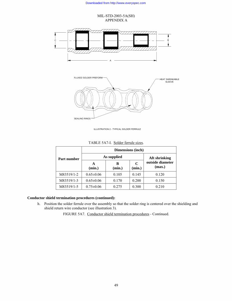
MIL-STD-2003-5A(SH) APPENDIX A
49
TABLE 5A7-I. Solder ferrule sizes.
Dimensions (inch)
As supplied Part number A
(min.) B
(min.) C
(min.)
Aft shrinking outside diameter
(max.)
M83519/1-2 0.65±0.06 0.105 0.145 0.120 M83519/1-3 0.65±0.06 0.170 0.200 0.150 M83519/1-5 0.75±0.06 0.275 0.300 0.210
Conductor shield termination procedures (continued):
h. Position the solder ferrule over the assembly so that the solder ring is centered over the shielding and shield return wire conductor (see illustration 3).
FIGURE 5A7. Conductor shield termination procedures - Continued.
C B
A
FLUXED SOLDER PREFORM
SEALING RINGS
HEAT SHRINKABLESLEEVE
ILLUSTRATION 2 - TYPICAL SOLDER FERRULE
Downloaded from http://www.everyspec.com

MIL-STD-2003-5A(SH) APPENDIX A
50
Conductor shield termination procedures (continued): CAUTION: Use extreme care while applying heat in order to avoid damaging the conductor insulation due to melting. i. Using a heat gun and thermal reflector, as appropriate, heat the assembly while rotating to achieve proper
solder penetration and uniform sleeve shrinkage (see illustration 4). (1) Apply heat until the solder brightens and starts to flow toward the thermoplastic inserts.
FIGURE 5A7. Conductor shield termination procedures - Continued.
ILLUSTRATION 4 - TYPICAL HEAT GUN
REFLECTOR
HEAT SHRINKABLE SLEEVE
SHIELD RETURN WIRE
SHIELDED CABLE
CONDUCTOR
3/8"
BRAIDED SHIELD
FLUX SOLDER PREFORM(SOLDER RING)
ASSEMBLY JUST PRIOR TO SOLDER FLOW
HEAT SHRINKABLE SLEEVE(SHRUNK TO REQUIRED FORM)
CONDUCTOR
SHIELD RETURN WIRE
SHIELDED CABLE
BRAIDED SHIELD
ILLUSTRATION 3 - SOLDER HAS FLOWED
Downloaded from http://www.everyspec.com

MIL-STD-2003-5A(SH) APPENDIX A
51
Conductor shield termination procedures (continued): j. Hold the assembly firmly until the solder joint is set. k. Inspect the solder ferrule.
(1) The exposed shield wire must be visible on both sides of the solder ring but not extend beyond the heat shrinkable inserts.
(2) The ferrule solder should appear continuous and smooth with concave fillet between shield and return wire lead.
(3) The insulation of the shield return must be enclosed under the heat shrinkable insert. (4) The thermoplastic insert should collapse over the shield return wire and conductor shielding. (5) The ferrule shield must not be cut, split, or have strands protruding.
l. Terminate shield return wire with other conductors in accordance with the applicable system connector assembly procedure.
5. Shield termination to a connector using the two-piece crimp ferrule method: a. Strip outer jacket from conductors, staggering the distances between each (see illustration 1). b. Trim the shields ½" to ¾" length (see illustration 5A).
FIGURE 5A7. Conductor shield termination procedures - Continued.
Downloaded from http://www.everyspec.com

MIL-STD-2003-5A(SH) APPENDIX A
52
Conductor shield termination procedures (continued): c. Determine the maximum conductor diameter (see individual lead stripping techniques, table 5A3-II) and
add 0.005". d. Select the inner ferrule from table 5A7-II having the inner diameter nearest, but larger than, the
dimension calculated in step 5.c. Ensure the inner ferrule meets the requirements of SAE-AS21608 and MS21981.
FIGURE 5A7. Conductor shield termination procedures - Continued.
ILLUSTRATION 5 - TWO PIECE GROUNDING CONNECTION FOR TERMINATING SHIELDED WIRE
METALLIC SHIELDING BRAID
CONDUCTOR OUTERJACKET
1/2 - 3/4"CONDUCTORINSULATION
OUTER FERRULE
A
B
C
D
E
F
G
ROTATE CONDUCTOR TO SPREADSHIELDING BRAID
INNER FERRULE PARTIALLY INSERTED
INSERT SHIELD RETURN LEADBETWEEN OUTER FERRULEAND SHIELD
INNER FERRULEFLUSH WITH OUTER
CONDUCTORINSULATION
CRIMP SHIELD RETURNLEAD
SHIELD RETURN WIRE
CONDUCTOR
INNER FERRULE
H
Downloaded from http://www.everyspec.com

MIL-STD-2003-5A(SH) APPENDIX A
53
TABLE 5A7-II. Shielded wire terminations: inner ferrule sizes.
Inner ferrule (nominal) Part number Color code
ID OD
MS21981-046 Tin 0.046 0.070 MS21981-058 Yellow 0.058 0.083 MS21981-063 Red 0.063 0.088 MS21981-071 Green 0.071 0.096 MS21981-080 Blue 0.080 0.104 MS21981-090 Orange 0.090 0.114 MS21981-096 Purple 0.096 0.119 MS21981-101 Yellow 0.101 0.124 MS21981-109 Red 0.109 0.131 MS21981-115 Tin 0.115 0.146 MS21981-124 Green 0.124 0.145 MS21981-128 Tin 0.128 0.152 MS21981-134 Orange 0.134 0.156 MS21981-149 Blue 0.149 0.179 MS21981-156 Red 0.156 0.192 MS21981-165 Tin 0.165 0.194 MS21981-175 Green 0.175 0.215 MS21981-187 Yellow 0.187 0.227 MS21981-194 Blue 0.194 0.225 MS21981-205 Orange 0.205 0.245 MS21981-219 Tin 0.219 0.248 MS21981-225 Yellow 0.225 0.256 MS21981-232 Red 0.232 0.263 MS21981-250 Green 0.250 0.281 MS21981-261 Blue 0.261 0.297 MS21981-266 Tin 0.266 0.297 MS21981-275 Orange 0.275 0.306 MS21981-281 Yellow 0.281 0.331 MS21981-287 Tin 0.287 0.327 MS21981-297 Red 0.297 0.335 MS21981-312 Purple 0.312 0.362 MS21981-375 Blue 0.375 0.406
Conductor shield termination procedures (continued):
e. Add 1⁄16" to the outer diameter of the inner ferrule selected in step 5.d. Select an insulated outer ferrule from table 5A7-III that meets the requirements of SAE-AS21608 and MS18121 with the above dimension as the minimum inner diameter.
FIGURE 5A7. Conductor shield termination procedures - Continued.
Downloaded from http://www.everyspec.com
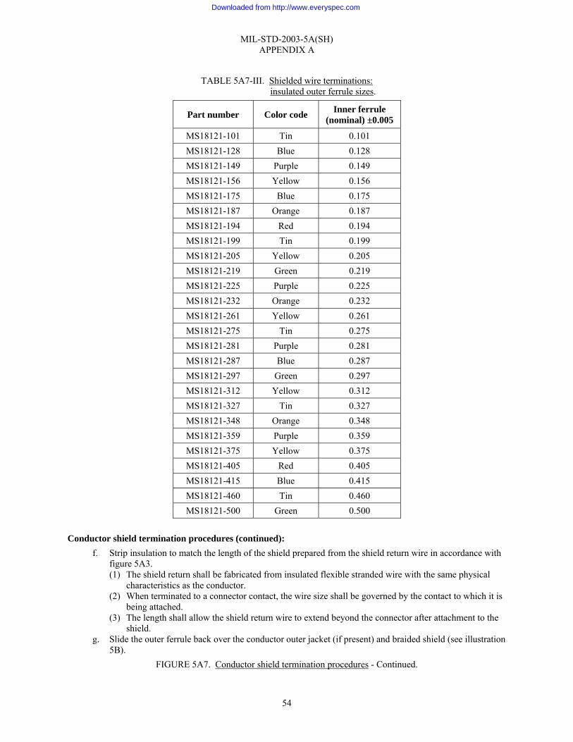
MIL-STD-2003-5A(SH) APPENDIX A
54
TABLE 5A7-III. Shielded wire terminations:
insulated outer ferrule sizes.
Part number Color code Inner ferrule (nominal) ±0.005
MS18121-101 Tin 0.101 MS18121-128 Blue 0.128 MS18121-149 Purple 0.149 MS18121-156 Yellow 0.156 MS18121-175 Blue 0.175 MS18121-187 Orange 0.187 MS18121-194 Red 0.194 MS18121-199 Tin 0.199 MS18121-205 Yellow 0.205 MS18121-219 Green 0.219 MS18121-225 Purple 0.225 MS18121-232 Orange 0.232 MS18121-261 Yellow 0.261 MS18121-275 Tin 0.275 MS18121-281 Purple 0.281 MS18121-287 Blue 0.287 MS18121-297 Green 0.297 MS18121-312 Yellow 0.312 MS18121-327 Tin 0.327 MS18121-348 Orange 0.348 MS18121-359 Purple 0.359 MS18121-375 Yellow 0.375 MS18121-405 Red 0.405 MS18121-415 Blue 0.415 MS18121-460 Tin 0.460 MS18121-500 Green 0.500
Conductor shield termination procedures (continued):
f. Strip insulation to match the length of the shield prepared from the shield return wire in accordance with figure 5A3. (1) The shield return shall be fabricated from insulated flexible stranded wire with the same physical
characteristics as the conductor. (2) When terminated to a connector contact, the wire size shall be governed by the contact to which it is
being attached. (3) The length shall allow the shield return wire to extend beyond the connector after attachment to the
shield. g. Slide the outer ferrule back over the conductor outer jacket (if present) and braided shield (see illustration
5B). FIGURE 5A7. Conductor shield termination procedures - Continued.
Downloaded from http://www.everyspec.com

MIL-STD-2003-5A(SH) APPENDIX A
55
Conductor shield termination procedures (continued): h. Rotate the conductor with a circular motion to flare out the braid (see illustration 5C). i. Place the inner ferrule under the shield braid so that 1⁄16" of sleeve sticks out beyond the braid (see
illustration 5D). (1) Ensure the shield return wire strands and shield braid strands are flat and smooth.
j. Insert the stripped end of the shield return wire under the outer ferrule and slide both forward over the shield braid and inner ferrule until flush with the braid and inner ferrule. NOTE: The shield return wire may extend from the front (when terminating to a contact) or rear (when terminated to another shield) of the outer ferrule as required.
k. Select a crimper and dies meeting the requirements of MIL-C-22520/5 or MIL-C-22520/10. (1) Test the crimping tool using an inspection gauge meeting the requirements of MIL-C-22520/6.
l. Place the ferrule assembly into the crimping tool, and crimp until the handle releases. m. Visually inspect the crimped ferrule assembly for fractures or chipping. Ensure the integrity of the
connection by giving the shield return wire a light finger tug. Reject any ferrules that do not meet the above criteria.
n. Terminate the shield return wire with other conductors in accordance with the applicable connector assembly procedure.
o. As an alternate to the step 5 method for shield return wire insertion under the outer ferrule, the following may be used: (1) Before the inner ferrule is placed under the shield braid, insert shield return wire under the inner
ferrule and fold back over as shown (illustration 5H). This method is intended to prevent the shield return wire from pulling out prior to crimping of the ferrule.
(2) The note associated with step 5.j is also applicable to this method. 6. Tying back and insulation of shields:
a. When system design does not require continuity of the conductor shield through a connector or to ground, the shield shall be terminated as follows: (1) Strip the conductor insulation to the length required by the applicable connector assembly procedure
in accordance with figure 5A3. (2) Trim the shield to a length of ⅜". (3) Comb out the shield braid using a spudger (or equivalent). (4) Fold the shield back over the conductor jacket. Ensure that the shield strands are flat and smooth. (5) Center a length of insulation sleeve over the folded back shield and shrink in place.
(a) Insulation sleeving shall meet the requirements of SAE-AMS-DTL-23053/5, Class 1. (b) The length shall be sufficient to completely cover the shield after shrinking.
7. Combining individual shields to common ground (daisy chain) (see illustration 6).
FIGURE 5A7. Conductor shield termination procedures - Continued.
NOTE THE STAGGEREDCONNECTIONS
ILLUSTRATION 6DAISY CHAINING SHIELD TERMINATIONS
Downloaded from http://www.everyspec.com
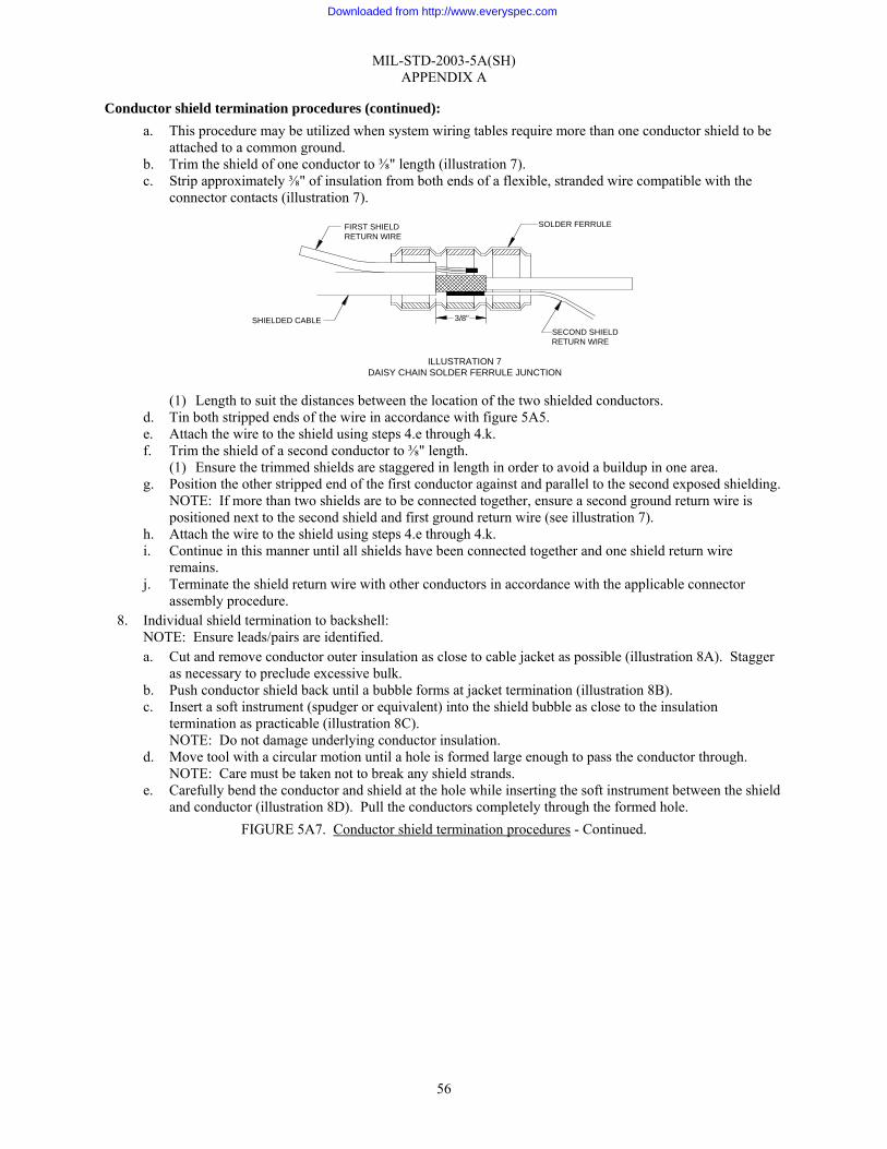
MIL-STD-2003-5A(SH) APPENDIX A
56
Conductor shield termination procedures (continued): a. This procedure may be utilized when system wiring tables require more than one conductor shield to be
attached to a common ground. b. Trim the shield of one conductor to ⅜" length (illustration 7). c. Strip approximately ⅜" of insulation from both ends of a flexible, stranded wire compatible with the
connector contacts (illustration 7).
(1) Length to suit the distances between the location of the two shielded conductors.
d. Tin both stripped ends of the wire in accordance with figure 5A5. e. Attach the wire to the shield using steps 4.e through 4.k. f. Trim the shield of a second conductor to ⅜" length.
(1) Ensure the trimmed shields are staggered in length in order to avoid a buildup in one area. g. Position the other stripped end of the first conductor against and parallel to the second exposed shielding.
NOTE: If more than two shields are to be connected together, ensure a second ground return wire is positioned next to the second shield and first ground return wire (see illustration 7).
h. Attach the wire to the shield using steps 4.e through 4.k. i. Continue in this manner until all shields have been connected together and one shield return wire
remains. j. Terminate the shield return wire with other conductors in accordance with the applicable connector
assembly procedure. 8. Individual shield termination to backshell:
NOTE: Ensure leads/pairs are identified. a. Cut and remove conductor outer insulation as close to cable jacket as possible (illustration 8A). Stagger
as necessary to preclude excessive bulk. b. Push conductor shield back until a bubble forms at jacket termination (illustration 8B). c. Insert a soft instrument (spudger or equivalent) into the shield bubble as close to the insulation
termination as practicable (illustration 8C). NOTE: Do not damage underlying conductor insulation.
d. Move tool with a circular motion until a hole is formed large enough to pass the conductor through. NOTE: Care must be taken not to break any shield strands.
e. Carefully bend the conductor and shield at the hole while inserting the soft instrument between the shield and conductor (illustration 8D). Pull the conductors completely through the formed hole.
FIGURE 5A7. Conductor shield termination procedures - Continued.
ILLUSTRATION 7DAISY CHAIN SOLDER FERRULE JUNCTION
SHIELDED CABLE
FIRST SHIELDRETURN WIRE
SECOND SHIELDRETURN WIRE
SOLDER FERRULE
3/8"
Downloaded from http://www.everyspec.com
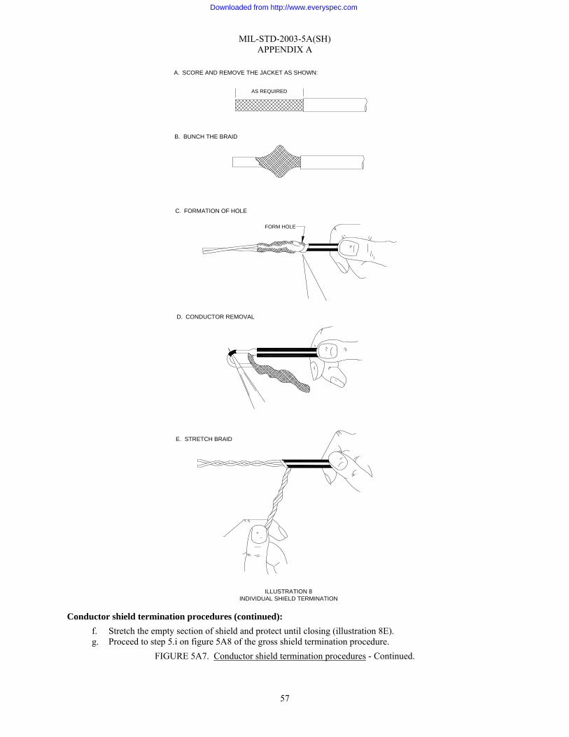
MIL-STD-2003-5A(SH) APPENDIX A
57
Conductor shield termination procedures (continued): f. Stretch the empty section of shield and protect until closing (illustration 8E). g. Proceed to step 5.i on figure 5A8 of the gross shield termination procedure.
FIGURE 5A7. Conductor shield termination procedures - Continued.
AS REQUIRED
ILLUSTRATION 8INDIVIDUAL SHIELD TERMINATION
A. SCORE AND REMOVE THE JACKET AS SHOWN:
B. BUNCH THE BRAID
C. FORMATION OF HOLE
FORM HOLE
D. CONDUCTOR REMOVAL
E. STRETCH BRAID
Downloaded from http://www.everyspec.com

MIL-STD-2003-5A(SH) APPENDIX A
58
Gross shield termination procedures: 1. Observe the following before terminating the gross shield:
a. Verify that the shield braiding is not cut, nicked, or scratched. b. Inspect all shield termination hardware (RFI rings, ferrules, etc.) to ensure they are the correct type, size,
and are free of tarnish, corrosion, or damage. 2. Gross shield termination shall be in accordance with applicable system wiring tables and diagrams utilizing
one of the methods outlined in this appendix. 3. Method 1 – Floating shield method:
a. This method is used when the system design does not require continuity of the shield through the connector or grounding of the shield.
b. Carefully comb out the shield using a spudger (or equivalent) (illustration 1).
c. Separate the unbraided shield wires into three equal groups. d. Twist each group into a tight self-contained bundle (pigtail) (illustration 2).
FIGURE 5A8. Gross shield termination procedures.
ILLUSTRATION 2GROSS SHIELD PIGTAILS
ILLUSTRATION 1COMBED OUT GROSS SHIELD
Downloaded from http://www.everyspec.com
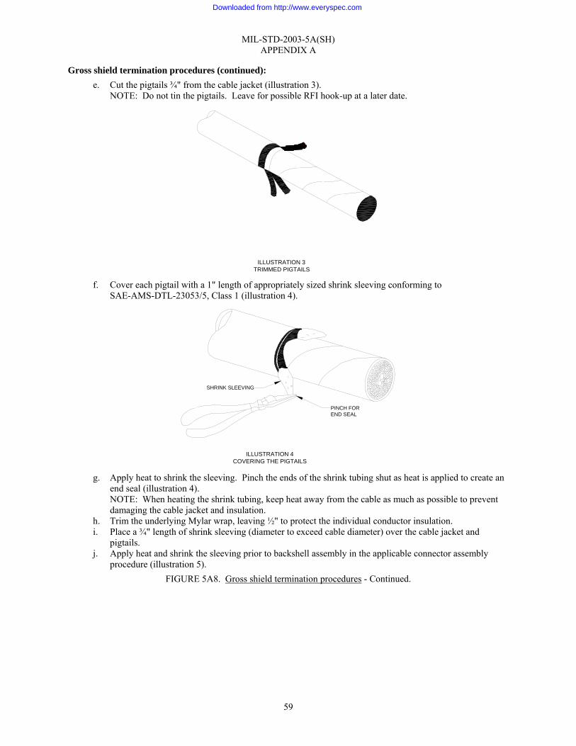
MIL-STD-2003-5A(SH) APPENDIX A
59
Gross shield termination procedures (continued): e. Cut the pigtails ¾" from the cable jacket (illustration 3).
NOTE: Do not tin the pigtails. Leave for possible RFI hook-up at a later date.
f. Cover each pigtail with a 1" length of appropriately sized shrink sleeving conforming to
SAE-AMS-DTL-23053/5, Class 1 (illustration 4).
g. Apply heat to shrink the sleeving. Pinch the ends of the shrink tubing shut as heat is applied to create an
end seal (illustration 4). NOTE: When heating the shrink tubing, keep heat away from the cable as much as possible to prevent damaging the cable jacket and insulation.
h. Trim the underlying Mylar wrap, leaving ½" to protect the individual conductor insulation. i. Place a ¾" length of shrink sleeving (diameter to exceed cable diameter) over the cable jacket and
pigtails. j. Apply heat and shrink the sleeving prior to backshell assembly in the applicable connector assembly
procedure (illustration 5). FIGURE 5A8. Gross shield termination procedures - Continued.
ILLUSTRATION 4COVERING THE PIGTAILS
PINCH FOREND SEAL
SHRINK SLEEVING
ILLUSTRATION 3TRIMMED PIGTAILS
Downloaded from http://www.everyspec.com
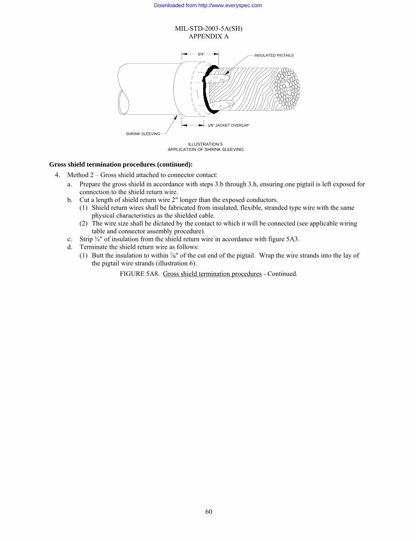
MIL-STD-2003-5A(SH) APPENDIX A
60
Gross shield termination procedures (continued): 4. Method 2 – Gross shield attached to connector contact:
a. Prepare the gross shield in accordance with steps 3.b through 3.h, ensuring one pigtail is left exposed for connection to the shield return wire.
b. Cut a length of shield return wire 2" longer than the exposed conductors. (1) Shield return wires shall be fabricated from insulated, flexible, stranded type wire with the same
physical characteristics as the shielded cable. (2) The wire size shall be dictated by the contact to which it will be connected (see applicable wiring
table and connector assembly procedure). c. Strip ¾" of insulation from the shield return wire in accordance with figure 5A3. d. Terminate the shield return wire as follows:
(1) Butt the insulation to within 1⁄16" of the cut end of the pigtail. Wrap the wire strands into the lay of the pigtail wire strands (illustration 6).
FIGURE 5A8. Gross shield termination procedures - Continued.
ILLUSTRATION 5APPLICATION OF SHRINK SLEEVING
SHRINK SLEEVING
1/8" JACKET OVERLAP
INSULATED PIGTAILS3/4"
Downloaded from http://www.everyspec.com
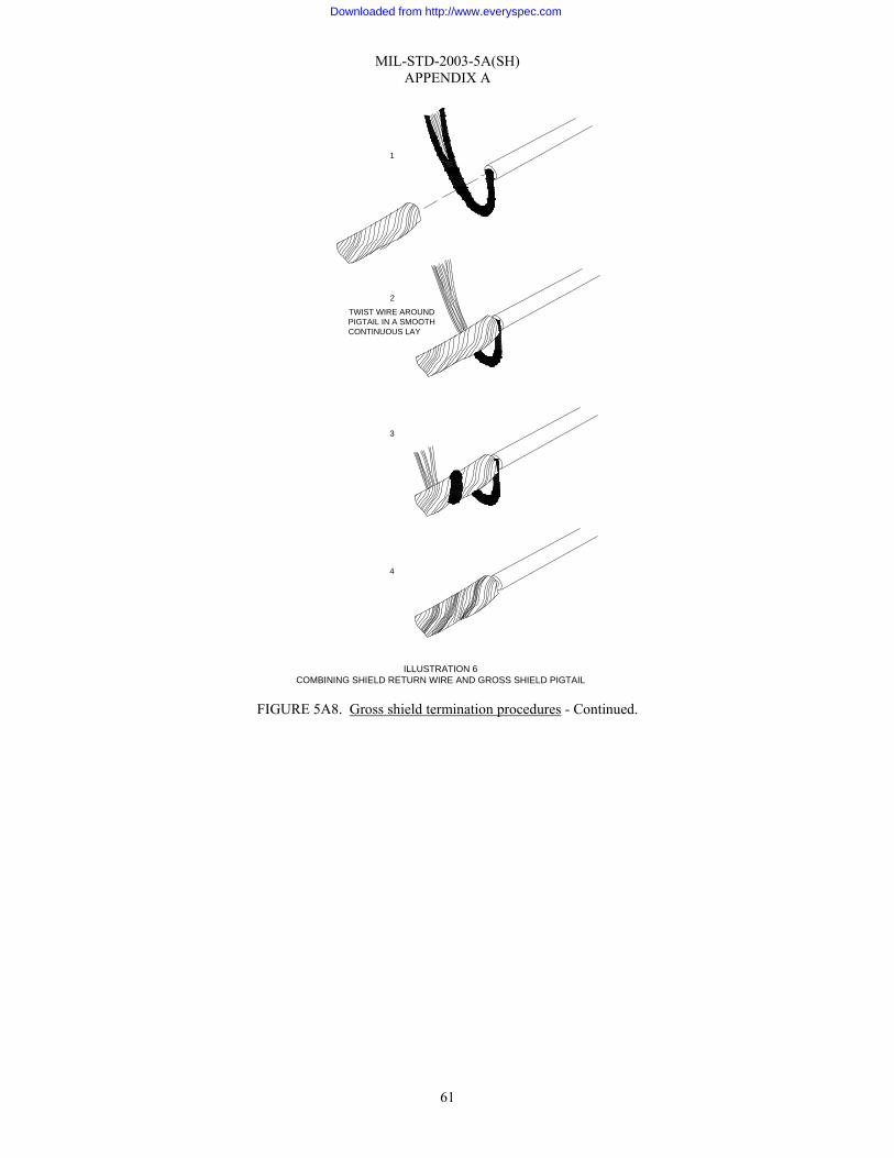
MIL-STD-2003-5A(SH) APPENDIX A
61
FIGURE 5A8. Gross shield termination procedures - Continued.
ILLUSTRATION 6COMBINING SHIELD RETURN WIRE AND GROSS SHIELD PIGTAIL
TWIST WIRE AROUNDPIGTAIL IN A SMOOTHCONTINUOUS LAY
1
2
3
4
Downloaded from http://www.everyspec.com

MIL-STD-2003-5A(SH) APPENDIX A
62
Gross shield termination procedures (continued): (2) Solder the shield return wire to the pigtail. The solder should appear continuous, smooth, and shiny
with a concave fillet between strands. See figure 5A6 for acceptance criteria. (3) Clean the soldered connection with approved solvent. (4) Cover the soldered connection with appropriately sized shrink tubing conforming to
SAE-AMS-DTL-23053/5 Class 1, of sufficient length to cover the exposed shield and solder connection. Shrink the tubing directing heat away from conductors to prevent damage.
e. Strain relief: (1) Place a ½" length of appropriately sized shrink tubing over the tubing applied in step 4.d(4). Loop
the shield return wire up through the shrink tubing to provide a strain relief for the shield return wire (illustration 7).
(2) Alternative method – Fold back the return wire and tie forming a strain relief using lacing.
FIGURE 5A8. Gross shield termination procedures - Continued.
ILLUSTRATION 7FORMING THE STRAIN RELIEF
Downloaded from http://www.everyspec.com

MIL-STD-2003-5A(SH) APPENDIX A
63
Gross shield termination procedures (continued): f. Place a ¾" length of shrink sleeving (diameter to exceed cable diameter) over the cable jacket and
pigtails. g. Apply heat and shrink the sleeving prior to backshell assembly in the applicable connector assembly
procedure. h. Terminate the shield return wire with other conductors in accordance with the applicable connector
assembly procedure. 5. Method 3 – Gross shield grounded to backshell (see illustration 8):
NOTE: The following assembly procedure is based on the nomenclature and hardware configuration depicted in illustration 8. Variations may occur and cause minor deviation from this procedure. a. Carefully comb out the gross shield using a soft instrument (spudger or equivalent). b. Assemble sleeve assembly (PC 2) to the connector plug (PC 1) and tighten. c. Measure the distance from the connector end to the aft end of the sleeve assembly. d. Remove the sleeve assembly and reposition on the cable in a location that will not interfere with
subsequent connector assembly. e. Trim the shield to the distance measured in step 5.c. f. Complete all steps in the applicable connector assembly procedure up to the backshell assembly section. g. Measure the distance from the connector aft end to the cable jacket. h. Measure the distance from the forward end of the sleeve assembly to a point midway on the taper of the
inner ferrule (RFI bell). The inner ferrule must be bottomed against the sleeve shoulder. i. Determine the desired length of the gross shield by subtracting the measurement of step 5.h from the
measurement of step 5.g. NOTE: Ensure gross shield pieces do not fall into the connector during trimming.
j. Trim the gross shield to the desired length. k. Assemble sleeve assembly (PC 2) to the connector plug (PC 1) and tighten. (See applicable connector
assembly procedure.) l. Slide inner ferrule (RFI bell) (PC 3) into sleeve assembly and seat on inner shoulder. m. If the applicable wiring tables call for individual conductor shields to be grounded to the backshell, push
the shields through the gross shield close to the end of the cable jacket and combine individual shield strands with the gross shield.
n. Flare the gross shield over the tapered end of the inner ferrule. FIGURE 5A8. Gross shield termination procedures - Continued.
Downloaded from http://www.everyspec.com
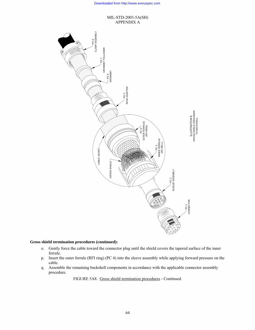
MIL-STD-2003-5A(SH) APPENDIX A
64
Gross shield termination procedures (continued): o. Gently force the cable toward the connector plug until the shield covers the tapered surface of the inner
ferrule. p. Insert the outer ferrule (RFI ring) (PC 4) into the sleeve assembly while applying forward pressure on the
cable. q. Assemble the remaining backshell components in accordance with the applicable connector assembly
procedure. FIGURE 5A8. Gross shield termination procedures - Continued.
PC
2S
LEE
VE
AS
SEM
BLY
PC
3IN
NE
R F
ER
RU
LE(R
FI B
ELL
)
PC 4
OU
TER
FE
RR
ULE
(RFI
RIN
G)
CA
BLE
JA
CKE
T
GR
OS
S S
HIE
LD
PC 5
RE
AR
AD
AP
TER
PC 6
GR
OM
ME
T
PC 7
GR
OM
MET
FO
LLO
WE
R
PC 8
CLA
MP
AS
SEM
BLY
PC 1
CO
NN
EC
TOR
ILLU
STR
ATI
ON
8G
RO
SS
SH
IELD
GR
OU
ND
ED
TO B
AC
KS
HE
LL
Downloaded from http://www.everyspec.com

MIL-STD-2003-5A(SH) APPENDIX A
65
Connector lockwiring techniques: 1. The following practices shall be observed when lockwiring connectors:
a. Connectors shall be lockwired with 0.020" diameter wire conforming to NASM20995. b. Connectors shall be lockwired individually. c. Lockwire shall not be reused. d. Damaged lockwire shall not be used. e. Backshells with holes in the coupling ring shall be lockwired.
2. Connectors must be lockwired when using 45-degree or 90-degree adapter assemblies (backshells) to prevent the loosening of the adapter coupling ring (see illustration 1).
3. Lockwire is not required if the coupling nut has set screws or other self locking provisions. 4. The following procedure shall be used to lockwire connectors (see illustration 2):
a. The parts shall be lockwired using a double twist in such a manner that when the coupling collar loosens, the lockwire shall be put in tension.
FIGURE 5A9. Connector lockwiring.
ILLUSTRATION 2LOCKWIRING THE CONNECTOR
ADAPTER COUPLING RING
ADAPTER COUPLING RING
ILLUSTRATION 1LOCATION OF LOCKWIRE
LOCKWIRE HOLES
CONNECTORCOUPLING RING
LOCKWIRE HOLE
Downloaded from http://www.everyspec.com

MIL-STD-2003-5A(SH) APPENDIX A
66
Connector lockwiring techniques (continued): b. When the backshell does not have a hole provided and there is no other provision for maintaining
backshell/connector orientation, a CRES hose clamp (A-A-52506, Type F, or equivalent) should be installed to secure the lockwire as depicted in illustration 3.
c. Measure the distance from the adapter coupling ring safety hole to backshell tab (or hose clamp) and add
2". d. Cut the lockwire twice the total dimension measured in step 4.c. e. Thread the lockwire through the selected adapter coupling ring hole. Pull ends together to even out the
legs of lockwire. f. Using lockwire pliers, twist lockwire from adapter coupling ring hole to backshell safety tab (or hose
clamp) forming 6 to 8 turns per inch. g. Thread one lockwire through the backshell lockwire tab (or hose clamp) and pull tight. h. Twist the remaining lockwire. Cut off the extra lockwire leaving a pigtail of ¼" to ½" (3 to 6 twists) and
bend back or under to prevent it from becoming a snag. (1) Ensure the lockwire is installed and twisted so that the loop at the safety holes stays down and does
not tend to come up over the hole and leave a slack loop (illustration 3). i. When optional extensions are used, the coupling nut on the optional extension must also be secured by
lockwire. j. If the clamp assembly has a safety wire hole installed, install lockwire between it and the adapter
assembly (see illustration 4). k. Ensure the hose clamp (if present) is securely tightened.
FIGURE 5A9. Connector lockwiring - Continued.
ILLUSTRATION 3USING A HOSE CLAMP
LOCKWIRE
HOSE CLAMP (SCREW ADJ)(A-A-52506, TYPE F)
Downloaded from http://www.everyspec.com
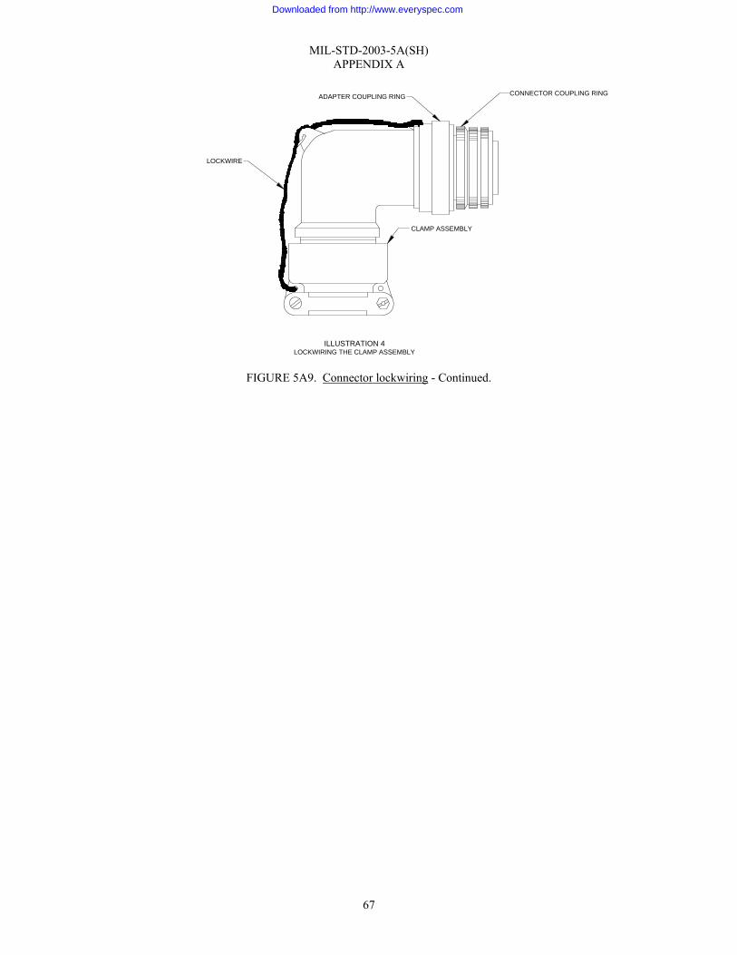
MIL-STD-2003-5A(SH) APPENDIX A
67
FIGURE 5A9. Connector lockwiring - Continued.
ADAPTER COUPLING RING CONNECTOR COUPLING RING
CLAMP ASSEMBLY
LOCKWIRE
ILLUSTRATION 4LOCKWIRING THE CLAMP ASSEMBLY
Downloaded from http://www.everyspec.com

MIL-STD-2003-5A(SH) APPENDIX A
68
Cable transflexing procedure: 1. Cable transflexing should be accomplished only after proper approval has been granted. 2. The purpose of transflexing a cable is to allow the cable to exceed the minimum bend radius requirement and
still provide a measure of mechanical and environmental protection to the individual conductors. 3. Cables shall be transflexed in accordance with the following procedure (see illustration 1).
a. Perform steps 1 and 2 of the applicable connector assembly procedure. Do not proceed beyond step 5 of cable preparation (figure 5A1).
b. Determine the length of cable to be transflexed. The length shall not exceed the distance as measured from the cable end to the point where the cable breaks out of its last hanger (18" maximum).
c. If the cable is armored, remove the armor 1½" beyond the length determined in step 3.b using an appropriate cable stripper. This ensures the armor will not interfere with the environmental seal between the cable jacket and transflex sleeving. (1) Install a ½" piece of heat shrink sleeving centered over the armor/jacket junction and shrink in place.
(a) Heat shrinkable sleeving shall meet the requirements of SAE-AMS-DTL-23053/5, Class1. d. Remove the cable jacket to the predetermined length as follows:
NOTE: Ensure the cut does not completely penetrate the jacket. (1) Score the circumference of the jacket with a multi-purpose cutter (OLFA 300 or equivalent). (2) Score the jacket piece to be removed along its length with a multi-purpose cutter. (3) Remove the jacket piece with needle nose pliers.
e. Do not damage gross shield (if applicable) or conductor insulation. f. Provide a length of heat shrinkable sleeving conforming to SAE-AMS-DTL-23053/5, Class 1 of the
proper diameter (table 5A10-I) that will cover the cable conductors, ensuring the following: FIGURE 5A10. Cable transflexing procedure.
Downloaded from http://www.everyspec.com
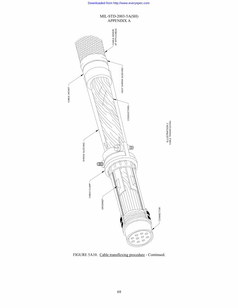
MIL-STD-2003-5A(SH) APPENDIX A
69
FIGURE 5A10. Cable transflexing procedure - Continued.
CO
NN
EC
TOR
ILLU
STR
ATI
ON
1C
AB
LE T
RA
NS
FLE
XIN
G
GR
OM
MET
CAB
LE C
LAM
P
SH
RIN
K S
LEE
VIN
G
CA
BLE
JA
CK
ET
CA
BLE
AR
MO
R(IF
AP
PLI
CA
BLE
)
CO
ND
UC
TOR
S
HE
AT
SH
RIN
K S
LEEV
ING
Downloaded from http://www.everyspec.com

MIL-STD-2003-5A(SH) APPENDIX A
70
Cable transflexing procedure (continued): (1) A minimum of 1" of overlay at the cable jacket. (2) Sleeving extends past the sealing gland in the backshell when the backshell is mated to the
connector. NOTE: Ensure longitudinal shrinkage is taken into consideration when making the above determination.
g. Cut and remove any filler or core used to make up the cable construction. NOTE: If the gross shield interferes with this step, push the braided shield back on the cable as depicted in illustration 2, while removing cable fillers.
h. Shrink a test piece of tubing over exposed conductors to check clamping and environmental sealing in
accordance with figure 5A1 (steps 6 and 8). (1) Build up the cable diameter in accordance with figure 5A2 if necessary.
i. Remove the test piece of tubing. Assemble the backshell and clamp components on the cable so as not to interfere with subsequent steps.
j. Slide the tubing selected in step 3.f over the exposed conductors onto the cable out of the work area. k. Hold exposed conductors and gross shield together with temporary ties.
FIGURE 5A10. Cable transflexing procedure - Continued.
ILLUSTRATION 2GROSS SHIELD INTERFERENCE REMOVAL
GROSS SHIELD
CONDUCTORS
CABLE JACKET
Downloaded from http://www.everyspec.com

MIL-STD-2003-5A(SH) APPENDIX A
71
TABLE 5A10-I. Heat shrink tubing (SAE-AMS-DTL-23053).
Military part number I.D. min. (as supplied) I.D. max. (as supplied) Wall thickness (after unrestricted shrinkage)
Class 1 M23053/5-101 1/ 0.046 0.023 0.016±0.003
102 1/ 0.063 0.031 0.017±0.003 103 1/ 0.093 0.046 0.020±0.003 104 1/ 0.125 0.062 0.020±0.003 105 1/ 0.187 0.093 0.020±0.003 106 1/ 0.250 0.125 0.025±0.003 107 1/ 0.375 0.187 0.025±0.003 108 1/ 0.500 0.250 0.025±0.003 109 1/ 0.750 0.375 0.030±0.003 110 1/ 1.000 0.500 0.035±0.005 111 1/ 1.500 0.750 0.040±0.006 112 1/ 2.000 1.000 0.045±0.007 113 1/ 3.000 1.500 0.050±0.008 114 1/ 4.000 2.000 0.055±0.009
Class 1 overexpanded M23053/5-115 1/ 1.000 0.275 0.045±0.005
116 1/ 2.000 0.550 0.045±0.005 117 1/ 3.000 0.810 0.045±0.005 118 1/ 4.000 1.050 0.045±0.005 119 1/ 1.000 0.462 0.045±0.005 120 1/ 2.375 0.680 0.045±0.005 121 1/ 3.000 0.840 0.045±0.005 122 1/ 3.750 0.930 0.045±0.005 123 1/ 4.500 1.450 0.045±0.005
FIGURE 5A10. Cable transflexing procedure - Continued.
Downloaded from http://www.everyspec.com

MIL-STD-2003-5A(SH) APPENDIX A
72
TABLE 5A10-I. Heat shrink tubing (SAE-AMS-DTL-23053) - Continued.
NOTE: 1/ Select color designators are as follows:
Designator Color 0 Black 1 Brown 2 Red 3 Orange 4 Yellow 5 Green 6 Blue 7 Violet (purple) 8 Gray (slate) 9 White P Pink T Tan
Cable transflexing procedure (continued):
l. Disassemble and relocate the backshell and clamp components on the cable. Verify that all parts are included and are in correct order and orientation. Assemble the backshell, and locate it on the cable so that it will not interfere with connector wiring.
m. Continue assembling the connector in accordance with the applicable connector assembly procedure commencing with step 12 of figure 5A1. NOTE: Terminate the gross shield (if applicable) inside the backshell forward of and not to interfere with the environmental seal. NOTE: Do not assemble the backshell to the connector until sequenced in this procedure.
n. Fold spare conductors back and insulate exposed ends with a ½" length of heat shrink tubing (illustration
3). (1) Position grommet follower if applicable.
o. If connector has individual lead sealing grommet, slide down over conductors and seat. (1) Clean the area with an approved solvent from table 5A10-II.
FIGURE 5A10. Cable transflexing procedure - Continued.
ILLUSTRATION 3TERMINATION OF SPARE CONDUCTORS
FOLD 1/2 WAY BACK
HEAT SHRINK TUBING
Downloaded from http://www.everyspec.com

MIL-STD-2003-5A(SH) APPENDIX A
73
TABLE 5A10-II. Approved solvents.
Solvent Specification
Isopropyl alcohol TT-I-735 Perchloroethylene ASTM D4376 Reagent water (Type II) ASTM D1193 Detergent cleaners As approved by the Government
procuring activity Cable transflexing procedure (continued):
p. Abrade bonding surface of cable jacket with #320 emory cloth or equivalent (illustration 4).
q. Apply adhesive to the abraded area of the cable jacket.
(1) Adhesive material must be of a type that will effectively seal the enclosed area against moisture (general purpose adhesive MMM-A-189 or equivalent).
r. Remove the temporary ties applied in step 3.k and position the heat shrinkable tubing over the cable conductors ensuring that the tubing overlaps the cable jacket by 1" and completely covers the environmental seal area. It will be necessary to use a heat gun to shrink the tubing sufficiently to pass the shrinkable tubing under the backshell components during positioning.
s. Position the backshell components away from the connector end, and using a heat gun, shrink the tubing starting at the connector end. When clear of the area that will be occupied by the backshell, slide the backshell components to the connector end.
t. Continue applying heat in the direction of the cable jacket, removing heat as the sleeving assumes the configuration of the cable conductors.
u. When the sleeving has recovered sufficiently to seal with the cable jacket and excess adhesive appears at the end, discontinue the heating process. CAUTION: Do not use solvent for cleaning off excess adhesive. Doing so could cause migration of the solvent into the bond line area and result in a potential bond failure.
v. Wipe off excess adhesive with a clean cloth. w. Assemble the backshell components to the connector in accordance with the applicable connector
assembly procedure. FIGURE 5A10. Cable transflexing procedure - Continued.
1 INCH
ARMOR (IF PRESENT)
HEAT SHRINK TUBING
BONDING AREA
CABLE JACKET
ILLUSTRATION 4CABLE JACKET PREPARATION
Downloaded from http://www.everyspec.com
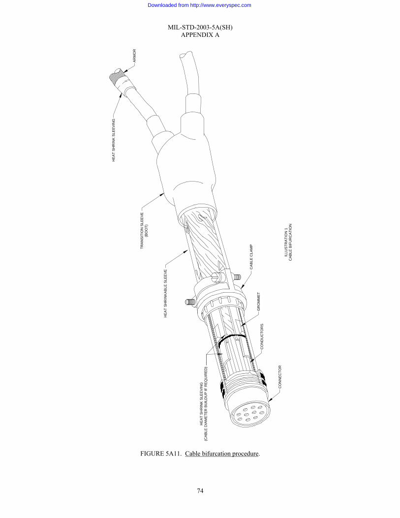
MIL-STD-2003-5A(SH) APPENDIX A
74
FIGURE 5A11. Cable bifurcation procedure.
CO
NN
EC
TOR
ILLU
STR
ATI
ON
1C
AB
LE B
IFU
RC
ATI
ON
GR
OM
ME
T
CA
BLE
CLA
MP
HE
AT
SH
RIN
KA
BLE
SLE
EV
E
CO
ND
UC
TOR
S
HE
AT
SH
RIN
K S
LEEV
ING
(CA
BLE
DIA
ME
TER
BU
ILD
UP
IF R
EQ
UIR
ED
)
TRA
NS
ITIO
N S
LEE
VE
(BO
OT)
HE
AT
SH
RIN
K S
LEE
VIN
G
AR
MO
R
Downloaded from http://www.everyspec.com

MIL-STD-2003-5A(SH) APPENDIX A
75
Cable bifurcation procedure: 1. Cable bifurcation in this procedure is the mating of two cables with a single connector. This procedure shall
ensure that an environmental seal exists and that adequate strain relief is provided (illustration 1). 2. The procedure for mating two cables will be as follows:
a. Determine the length from the connector where the mating of the two cables will occur. (1) This distance shall not exceed the distance to the breakout of the two cables from their last wireway
hanger (18" maximum). b. Prepare each cable in accordance with figure 5A1, steps 1 through 5. c. Remove the cable jacket of each cable in accordance with figure 5A1, step 9.d, to the point of juncture of
the two cables. (1) If one or both of the cables is armored, remove the armor from the cables(s) at a point 2" beyond the
point of juncture using a cable stripper. (2) Shrink a 1" piece of heat shrinkable tubing meeting the requirements of SAE-AMS-DTL-23053/5,
Class 1, centered at the end of the armor to terminate the armor on the cable jacket. (3) Do not damage gross shield or conductor insulation.
d. Cut and remove any filler or core used to make up the cable construction. NOTE: If the gross shield interferes with this step, push the braided shield back on the cable as depicted in illustration 2 while removing cable fillers.
e. Determine the diameters of the two cables to be bifurcated and the resultant wire bundle and select the
appropriately sized “Y” transition sleeve (boot). (1) Material for the boot shall be polyolefin, semi-rigid, non-burning and shall conform to the
requirements of SAE-AS81765/1. The boot shall have an internal coating of adhesive. (2) If one boot will not fit the cables at all legs, select a size that fits as many legs as possible and is too
large for the remaining legs. The cable(s) should then be built up to the proper diameter with adhesive-coated heat shrinkable tubing conforming to SAE-AMS-DTL-23053/15, Class 1.
f. Slide the legs of the boot over the cables and position away from the work area. g. Carefully comb out the gross shield using a soft instrument (spudger or equivalent) to junction of the two
cables. h. Mark all conductors. i. Interweave the leads from both cables to form a single cable. The conductors of the combined cable
must exhibit the same lay (clockwise or counterclockwise rotation) and relative position as the original single cable conductors.
FIGURE 5A11. Cable bifurcation procedure - Continued.
ILLUSTRATION 2GROSS SHIELD INTERFERENCE REMOVAL
GROSS SHIELD
CONDUCTORS
CABLE JACKET
Downloaded from http://www.everyspec.com
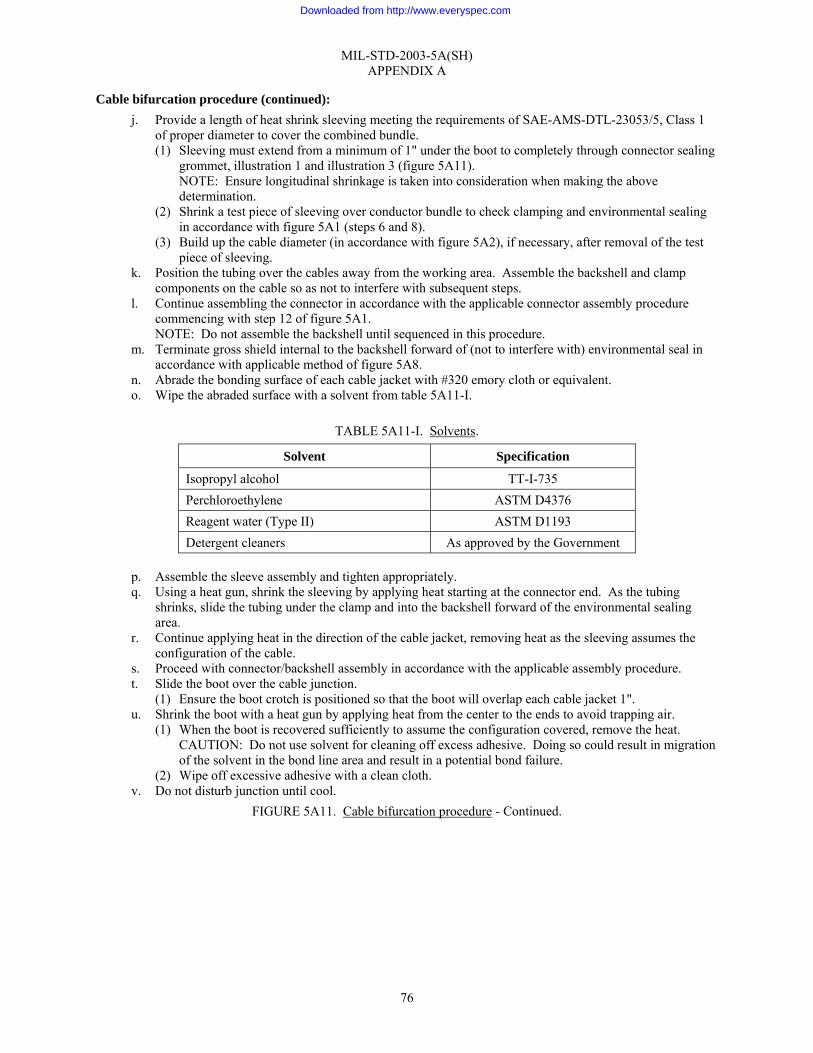
MIL-STD-2003-5A(SH) APPENDIX A
76
Cable bifurcation procedure (continued): j. Provide a length of heat shrink sleeving meeting the requirements of SAE-AMS-DTL-23053/5, Class 1
of proper diameter to cover the combined bundle. (1) Sleeving must extend from a minimum of 1" under the boot to completely through connector sealing
grommet, illustration 1 and illustration 3 (figure 5A11). NOTE: Ensure longitudinal shrinkage is taken into consideration when making the above determination.
(2) Shrink a test piece of sleeving over conductor bundle to check clamping and environmental sealing in accordance with figure 5A1 (steps 6 and 8).
(3) Build up the cable diameter (in accordance with figure 5A2), if necessary, after removal of the test piece of sleeving.
k. Position the tubing over the cables away from the working area. Assemble the backshell and clamp components on the cable so as not to interfere with subsequent steps.
l. Continue assembling the connector in accordance with the applicable connector assembly procedure commencing with step 12 of figure 5A1. NOTE: Do not assemble the backshell until sequenced in this procedure.
m. Terminate gross shield internal to the backshell forward of (not to interfere with) environmental seal in accordance with applicable method of figure 5A8.
n. Abrade the bonding surface of each cable jacket with #320 emory cloth or equivalent. o. Wipe the abraded surface with a solvent from table 5A11-I.
TABLE 5A11-I. Solvents.
Solvent Specification
Isopropyl alcohol TT-I-735 Perchloroethylene ASTM D4376 Reagent water (Type II) ASTM D1193 Detergent cleaners As approved by the Government
p. Assemble the sleeve assembly and tighten appropriately. q. Using a heat gun, shrink the sleeving by applying heat starting at the connector end. As the tubing
shrinks, slide the tubing under the clamp and into the backshell forward of the environmental sealing area.
r. Continue applying heat in the direction of the cable jacket, removing heat as the sleeving assumes the configuration of the cable.
s. Proceed with connector/backshell assembly in accordance with the applicable assembly procedure. t. Slide the boot over the cable junction.
(1) Ensure the boot crotch is positioned so that the boot will overlap each cable jacket 1". u. Shrink the boot with a heat gun by applying heat from the center to the ends to avoid trapping air.
(1) When the boot is recovered sufficiently to assume the configuration covered, remove the heat. CAUTION: Do not use solvent for cleaning off excess adhesive. Doing so could result in migration of the solvent in the bond line area and result in a potential bond failure.
(2) Wipe off excessive adhesive with a clean cloth. v. Do not disturb junction until cool.
FIGURE 5A11. Cable bifurcation procedure - Continued.
Downloaded from http://www.everyspec.com
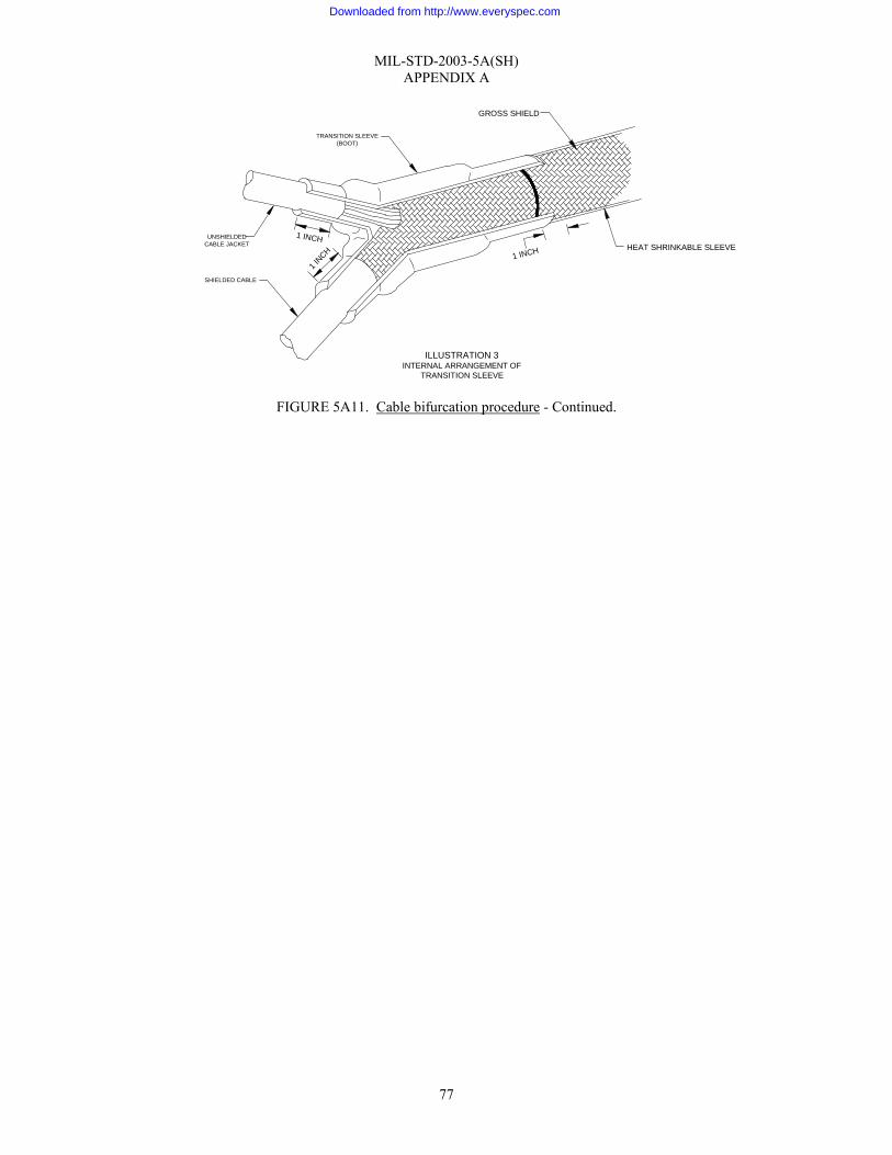
MIL-STD-2003-5A(SH) APPENDIX A
77
FIGURE 5A11. Cable bifurcation procedure - Continued.
TRANSITION SLEEVE(BOOT)
ILLUSTRATION 3INTERNAL ARRANGEMENT OF
TRANSITION SLEEVE
GROSS SHIELD
HEAT SHRINKABLE SLEEVE1 INCH
1 INCH
1 INCH
SHIELDED CABLE
UNSHIELDEDCABLE JACKET
Downloaded from http://www.everyspec.com
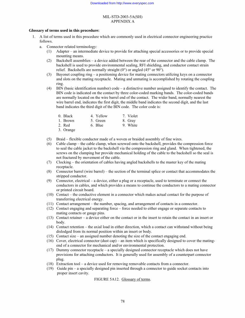
MIL-STD-2003-5A(SH) APPENDIX A
78
Glossary of terms used in this procedure: 1. A list of terms used in this procedure which are commonly used in electrical connector engineering practice
follows. a. Connector related terminology:
(1) Adapter – an intermediate device to provide for attaching special accessories or to provide special mounting means.
(2) Backshell assemblies – a device added between the rear of the connector and the cable clamp. The backshell is used to provide environmental sealing, RFI shielding, and conductor contact strain relief. Backshells are normally straight (0°) or angled (45° or 90°).
(3) Bayonet coupling ring – a positioning device for mating connectors utilizing keys on a connector and slots on the mating receptacle. Mating and unmating is accomplished by rotating the coupling ring.
(4) BIN (basic identification number) code – a distinctive number assigned to identify the contact. The BIN code is indicated on the contact by three color-coded marking bands. The color-coded bands are normally located on the wire barrel end of the contact. The wider band, normally nearest the wire barrel end, indicates the first digit, the middle band indicates the second digit, and the last band indicates the third digit of the BIN code. The color code is:
0. Black 4. Yellow 7. Violet 1. Brown 5. Green 8. Gray 2. Red 6. Blue 9. White 3. Orange
(5) Braid – flexible conductor made of a woven or braided assembly of fine wires. (6) Cable clamp – the cable clamp, when screwed onto the backshell, provides the compression force
to seal the cable jacket to the backshell via the compression ring and gland. When tightened, the screws on the clamping bar provide mechanical holding of the cable to the backshell so the seal is not fractured by movement of the cable.
(7) Clocking – the orientation of cables having angled backshells to the master key of the mating receptacle.
(8) Connector barrel (wire barrel) – the section of the terminal splice or contact that accommodates the stripped conductor.
(9) Connector, electrical – a device, either a plug or a receptacle, used to terminate or connect the conductors in cables, and which provides a means to continue the conductors to a mating connector or printed circuit board.
(10) Contact – the conductive element in a connector which makes actual contact for the purpose of transferring electrical energy.
(11) Contact arrangement – the number, spacing, and arrangement of contacts in a connector. (12) Contact engaging and separating force – force needed to either engage or separate contacts to
mating contacts or gauge pins. (13) Contact retainer – a device either on the contact or in the insert to retain the contact in an insert or
body. (14) Contact retention – the axial load in either direction, which a contact can withstand without being
dislodged from its normal position within an insert or body. (15) Contact size – an assigned number denoting the size of the contact engaging end. (16) Cover, electrical connector (dust cap) – an item which is specifically designed to cover the mating-
end of a connector for mechanical and/or environmental protection. (17) Dummy connector receptacle – a specially designed connector receptacle which does not have
provisions for attaching conductors. It is generally used for assembly of a counterpart connector plug.
(18) Extraction tool – a device used for removing removable contacts from a connector. (19) Guide pin – a specially designed pin inserted through a connector to guide socket contacts into
proper insert cavity. FIGURE 5A12. Glossary of terms.
Downloaded from http://www.everyspec.com
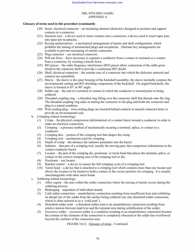
MIL-STD-2003-5A(SH) APPENDIX A
79
Glossary of terms used in this procedure (continued): (20) Insert, electrical connector – an insulating element (dielectric) designed to position and support
contacts in a connector. (21) Insertion tool – a device used to insert contacts into a connector; a device used to insert taper pins
into taper pin receptacles. (22) Keying (polarization) – a mechanical arrangement of inserts and shell configuration, which
prohibits the mating of mismatched plugs and receptacles. Alternate key arrangements are available to prevent mismating of similar connectors.
(23) Plug connector – see electrical connector. (24) Pull-out force – force necessary to separate a conductor from a contact or terminal or a contact
from a connector, by exerting a tensile force. (25) RFI pieces – the radio frequency interference (RFI) pieces allow connection of the cable gross
shield to the connector shell to provide a continuous RFI shield. (26) Shell, electrical connector – the outside case of a connector into which the dielectric material and
contacts are assembled. (27) Sleeve – the sleeve is the outer housing of the backshell assembly; the sleeve normally contains the
environmental sealing and RFI shielding components of the backshell. On angled backshells, the sleeve is formed at 45° or 90° angle.
(28) Solder cup – the end of a terminal or contact in which the conductor is inserted prior to being soldered.
(29) Threaded coupling ring – a threaded ring fitting over the connector shell that threads onto the ring. The threaded coupling ring aides in mating the connector to the plug and holds the connector and plug in a mated condition.
(30) Wire-sealing plug – wire-sealing plugs are inserted behind contacts in unused connector holes to provide an environmental seal.
b. Crimping related terminology: (1) Crimp – the physical compression (deformation) of a contact barrel around a conductor in order to
make an electrical connection. (2) Crimping – a pressure method of mechanically securing a terminal, splice, or contact to a
conductor. (3) Crimping dies – portion of the crimping tool that shapes the crimp. (4) Crimping tool – mechanism used for crimping. (5) Depth of crimp – the distance the indentor penetrates into the barrel. (6) Indentor – that part of a crimping tool, usually the moving part, that compresses indentations in the
contact conductor barrel. (7) Locator – the part of the crimping die, positioner, or turret head that places the terminal, splice, or
contact in the correct crimping area of the crimping tool or die. (8) Positioner – see locator. (9) Ratchet control – a device to ensure the full crimping cycle of a crimping tool. (10) Turret head – a device that is attached to a crimping tool which contains more than one locator and
allows the locators to be rotated to hold a contact in the correct position for crimping. It is usually interchangeable with other turret heads.
c. Soldering related terminology: (1) Alloy region – the area within the solder connection where the mixing of metals occurs during the
soldering process. (2) Birdcaging – separation of individual strands. (3) Cold solder connection – unsatisfactory connection resulting from insufficient heat and exhibiting
an abrupt rise of the solder from the surface being soldered (see also disturbed solder connection, which is often referred to as a “cold joint”).
(4) Disturbed solder joint – a disturbed solder joint is an unsatisfactory connection resulting from relative motion between lead/wire and the terminal area during solidification of the solder.
(5) Excessive solder – excessive solder is a condition resulting in an unsatisfactory connection because the contour of the elements of the connection is completely obscured or the solder has overflowed beyond the confines of the connection area.
FIGURE 5A12. Glossary of terms - Continued.
Downloaded from http://www.everyspec.com
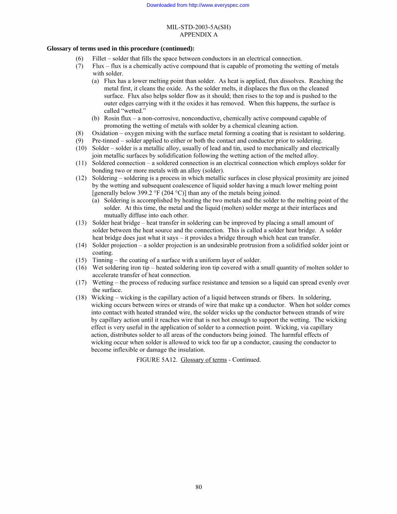
MIL-STD-2003-5A(SH) APPENDIX A
80
Glossary of terms used in this procedure (continued): (6) Fillet – solder that fills the space between conductors in an electrical connection. (7) Flux – flux is a chemically active compound that is capable of promoting the wetting of metals
with solder. (a) Flux has a lower melting point than solder. As heat is applied, flux dissolves. Reaching the
metal first, it cleans the oxide. As the solder melts, it displaces the flux on the cleaned surface. Flux also helps solder flow as it should; then rises to the top and is pushed to the outer edges carrying with it the oxides it has removed. When this happens, the surface is called “wetted.”
(b) Rosin flux – a non-corrosive, nonconductive, chemically active compound capable of promoting the wetting of metals with solder by a chemical cleaning action.
(8) Oxidation – oxygen mixing with the surface metal forming a coating that is resistant to soldering. (9) Pre-tinned – solder applied to either or both the contact and conductor prior to soldering. (10) Solder – solder is a metallic alloy, usually of lead and tin, used to mechanically and electrically
join metallic surfaces by solidification following the wetting action of the melted alloy. (11) Soldered connection – a soldered connection is an electrical connection which employs solder for
bonding two or more metals with an alloy (solder). (12) Soldering – soldering is a process in which metallic surfaces in close physical proximity are joined
by the wetting and subsequent coalescence of liquid solder having a much lower melting point [generally below 399.2 °F (204 °C)] than any of the metals being joined. (a) Soldering is accomplished by heating the two metals and the solder to the melting point of the
solder. At this time, the metal and the liquid (molten) solder merge at their interfaces and mutually diffuse into each other.
(13) Solder heat bridge – heat transfer in soldering can be improved by placing a small amount of solder between the heat source and the connection. This is called a solder heat bridge. A solder heat bridge does just what it says – it provides a bridge through which heat can transfer.
(14) Solder projection – a solder projection is an undesirable protrusion from a solidified solder joint or coating.
(15) Tinning – the coating of a surface with a uniform layer of solder. (16) Wet soldering iron tip – heated soldering iron tip covered with a small quantity of molten solder to
accelerate transfer of heat connection. (17) Wetting – the process of reducing surface resistance and tension so a liquid can spread evenly over
the surface. (18) Wicking – wicking is the capillary action of a liquid between strands or fibers. In soldering,
wicking occurs between wires or strands of wire that make up a conductor. When hot solder comes into contact with heated stranded wire, the solder wicks up the conductor between strands of wire by capillary action until it reaches wire that is not hot enough to support the wetting. The wicking effect is very useful in the application of solder to a connection point. Wicking, via capillary action, distributes solder to all areas of the conductors being joined. The harmful effects of wicking occur when solder is allowed to wick too far up a conductor, causing the conductor to become inflexible or damage the insulation.
FIGURE 5A12. Glossary of terms - Continued.
Downloaded from http://www.everyspec.com

MIL-STD-2003-5A(SH) APPENDIX A
81
Tooling and materials list: 1. The following tools are utilized in the assembly of typical connectors:
a. Solvent brush is used for cleaning dirt and other foreign material from connector and backshell parts. b. Artist’s brush is used for applying petrolatum and other approved lubricants to connector and backshell
parts. c. Precision mechanical stripper is used to remove insulation from conductors using blades. It consists of
an adjustable stop to control the length of insulation removed. d. Soldering iron is used to heat conductors and solder to provide a secure electrical connection. e. Heat gun is used to heat shrink solder sleeves and shrinkable tubing. f. Diagonal cutter is used to cut conductors to length, cut off a rejected crimped contact, and trim stripped
conductor wires to length. g. Cable shears are used to cut multi-conductor cable squarely. h. Adjustable cutter is used to cut cable jackets and insulation because it is totally adjustable to prevent
penetration to the underlying jacket conductors/braided shield and has a breakaway renewable blade. i. Soft instrument (spudger) is a pointed instrument used to comb out the shield prior to pigtailing. It is also
used to find and route conductors during connector insertion. j. Tailor shears are used to cut Mylar® tape and lacing tape. k. Needle nose pliers are used to peel off the scored cable jacket. l. Crows foot wrench is used to tighten the adapter onto the connector. m. Strap wrench is used to tighten various backshell components (i.e., sleeve to adapter and cable clamp to
sleeve). n. Tweezers are an alternative to fingers in tight rework situations. o. Cable stripper is used to remove armor, if present, from cables because it is adjustable to prevent
penetration to the underlying cable jacket. p. Crimping tool is used to fasten wire conductors into crimp contacts. q. Positioner is used to position the contact in the crimping tool indentors close to the proper depth. r. Crimping tool gauge provides a “GO”/“NO GO” test to make sure the crimp tool indentors close to the
proper depth. s. Pin contact gauge is used to test socket contact tension. t. Pin vise is used to hold the pin contact gauge. u. Dummy receptacle holds and transfers guide pins used for insertion of socket contacts and provides a
holding base for the connector during insertion of contacts. v. Guide pins provide a definite, unobstructed path for contacts to follow, prevent foreign material from
accumulating inside the socket contact, and prevent misalignment caused by bunching of the connector insert.
w. Connector assembly fixture holds the cable and connector relation to each other and prevents movement of the conductors after they have been inserted. Any assembly fixture that provides the attributes listed in the assembly portions of this procedure will be adequate.
x. Insertion tool is used to install contacts into the connector contact holes. y. Extraction tool is used to remove contacts from the connector. z. Lockwire pliers are used to twist the lockwire and to cut the lockwire.
2. The following materials are utilized in connector assembly procedures: a. Petrolatum is the pharmaceutical name for petroleum jelly or Vaseline® and is used to lubricate connector
and backshell components. b. Shrink tubing conforms to SAE-AMS-DTL-23053 and is used to insulate shield pigtails, for
identification of twisted pairs or triads, and to provide environmental protection. c. Lacing tape is used to form a strain relief for the shield return wire. d. Transition sleeve (boot) is used at the juncture when bifurcating two cables.
FIGURE 5A13. Tooling and materials list.
Downloaded from http://www.everyspec.com
MIL-STD-2003-5A(SH) APPENDIX A
82
Tooling and materials list (continued): e. Solder sleeve consists of a heat shrinkable sleeve containing a preform of fluxed solder at the center and
a thermoplastic sealing ring at each end. f. Transparent sleeving is used to provide environmental protection to exposed conductors and conforms to
SAE-AMS-DTL-23053/5 Class 1. g. Solvents are used to remove grease, oil, dirt, flux, and other debris from the connector and backshell
components and the cable jacket. h. Lockwire conforming to NASM20995 NC20 is used on connectors to prevent threaded parts from
backing off. 3. Pin pull tests, contact push tests, and torque-controlled screwdrivers and wrenches, which were required in
the past are no longer required. Care has been taken to eliminate all references to pin pull tests, contact push tests, and torque-controlled screwdrivers and wrenches.
FIGURE 5A13. Tooling and materials list - Continued.
Downloaded from http://www.everyspec.com

MIL-STD-2003-5A(SH) APPENDIX A
83
FIGURE 5A14. Connector part number nomenclature.
SPE
CIF
ICA
TIO
N N
UM
BER
THIS
PR
OC
ED
UR
E EN
ABLE
S TH
E A
SS
EM
BLE
R T
O B
RE
AK
DO
WN
AC
ON
NE
CTO
R P
AR
T N
UM
BER
INTO
ITS
CO
MP
ON
ENTS
AN
D D
ETE
RM
INE
THE
PH
YS
ICA
L C
HA
RA
CTE
RIS
TIC
S O
F TH
E C
ON
NE
CTO
R.
1. M
8151
1 R
EV
. B C
ON
NEC
TOR
S
M81
511/
01E
18-8
5P1
SH
ELL
TYP
E
/01
SQ
UA
RE
FLA
NG
E R
ECEP
TAC
LES
ER
IES
2 ST
AND
AR
D/0
2S
OLD
ER F
LAN
GE
REC
EPT
AC
LEH
ERM
ETI
C S
ER
IES
2 S
TAN
DA
RD
/03
SIN
GLE
HO
LE M
TG. R
EC
EPT
ACLE
SE
RIE
S 2
STAN
DA
RD
/04
SIN
GLE
HO
LE M
TG. R
EC
EPT
ACLE
HER
ME
TIC
SE
RIE
S 2
STA
ND
AR
D/0
5C
AB
LE R
EC
EPT
AC
LES
ER
IES
2 ST
AND
AR
D/0
6S
TRAI
GH
T PL
UG
SER
IES
2S
TAN
DA
RD
/21
SQ
UA
RE
FLA
NG
E R
ECEP
TAC
LES
ERIE
S 1
LON
G/2
2S
OLD
ER F
LAN
GE
REC
EPT
AC
LEH
ERM
ETI
C S
ER
IES
1 L
ON
G/2
3S
ING
LE H
OLE
MTG
. RE
CE
PTAC
LES
ER
IES
1 LO
NG
/24
SIN
GLE
HO
LE M
TG. R
EC
EPT
ACLE
HER
ME
TIC
SE
RIE
S 1
LO
NG
/25
CA
BLE
RE
CE
PTA
CLE
SE
RIE
S 1
LON
G/2
6S
TRAI
GH
T PL
UG
SER
IES
1 LO
NG
ALT
ER
NA
TE S
HE
LL P
OS
ITIO
NS
1, 2
, 3, 4
, 5, 6
INS
ER
T AR
RAN
GE
MEN
T03
04
05
07
09
11
12
14
19
21
24
27 3
2 3
7 3
8 4
1 4
5 5
5 6
1 7
4 8
5 9
212
1(01
)* 1
55(0
1)*
SH
ELL
SIZ
E08
10
14
16
18
20*
22*
24*
*AV
AIL
ABL
E O
NLY
IN S
ER
IES
1 -
LON
G
CLA
SS
E -
EN
VIR
ON
ME
NTA
LH
- H
ER
MET
ICP
- P
OTT
ED
EG
RO
MM
ET
SEA
L C
ON
NEC
TOR
S (1
50 °
CX
OPE
RA
TIN
G T
EMPE
RA
TUR
E).
FG
RO
MM
ET
SEA
L C
ON
NEC
TOR
S (1
75 °
CX
XO
PER
ATI
NG
TEM
PER
ATU
RE
), FL
UID
RE
SIS
TAN
T.
AG
RO
MM
ET
SEA
L C
ON
NEC
TOR
S (2
00 °
CX
XO
PER
ATI
NG
TEM
PER
ATU
RE
), FL
UID
RE
SIS
TAN
T.
HH
ER
ME
TIC
SE
AL
CO
NN
EC
TOR
S (1
50 °
CX
OP
ERA
TIN
G T
EM
PE
RA
TUR
E), S
OLD
ER
TER
MIN
ATE
D, F
ER
RO
US
ALL
OY
SH
ELL.
DH
ER
ME
TIC
SE
AL
CO
NN
EC
TOR
S (1
75 °
CX
OP
ERA
TIN
G T
EM
PE
RA
TUR
E), S
OLD
ER
TER
MIN
ATE
D, F
ER
RO
US
ALL
OY
SH
ELL,
FLU
ID R
ESIS
TAN
T.
GH
ER
ME
TIC
SE
AL
CO
NN
EC
TOR
S (1
75 °
CX
OP
ERA
TIN
G T
EM
PE
RA
TUR
E), S
OLD
ER
TER
MIN
ATE
D, C
OR
RO
SIO
N R
ESIS
TAN
TST
EEL
SH
ELL
, FLU
ID R
ESI
STA
NT.
LH
ER
ME
TIC
SE
AL
CO
NN
EC
TOR
S (1
75 °
CX
OPE
RA
TIN
G T
EMPE
RA
TUR
E),
CR
IMP
TER
MIN
ATE
D, F
ER
RO
US
ALL
OY
SH
ELL,
FLU
ID R
ESIS
TAN
T.
BH
ER
ME
TIC
SE
AL
CO
NN
EC
TOR
S (2
00 °
CX
OP
ERA
TIN
G T
EM
PE
RA
TUR
E), S
OLD
ER
TER
MIN
ATE
D, C
OR
RO
SIO
N R
ESIS
TAN
TST
EEL
SH
ELL
, FLU
ID R
ESI
STA
NT.
PPO
TTIN
G S
EAL
CO
NN
ECTO
RS
(150
°C
XO
PER
ATI
NG
TEM
PER
ATU
RE
).
TPO
TTIN
G S
EAL
CO
NN
ECTO
RS
(175
°C
XO
PER
ATI
NG
TEM
PER
ATU
RE
), FL
UID
RE
SIS
TAN
T.
CPO
TTIN
G S
EAL
CO
NN
ECTO
RS
(200
°C
XO
PER
ATI
NG
TEM
PER
ATU
RE
), FL
UID
RE
SIS
TAN
T.
WG
RO
MM
ET
SEA
L C
ON
NEC
TOR
S (1
75 °
CX
OPE
RA
TIN
G T
EMPE
RA
TUR
E),
FLU
IDR
ES
ISTA
NC
E, 5
00 H
OU
RS
SAL
T SP
RA
Y.
CO
NTA
CT
STY
LEP
PIN
SS
OC
KET
APP
LIC
ABLE
SER
IES
CLA
SSD
ES
CR
IPTI
ON
1 AN
D 2
3 A
ND
4
SH
ELL
PO
LAR
IZAT
ION
. TH
E P
OLA
RIZ
ATIO
N O
F TH
E M
ATIN
GP
LUG
S A
ND
REC
EPTA
CLE
S S
HAL
L B
E A
CC
OM
PLI
SH
ED
BY
MEA
NS
OF
MA
TIN
G IN
TEG
RA
L K
EYS
ON
TH
E P
LUG
SH
ELL
AN
DK
EYW
AY
S O
N T
HE
RE
CE
PTA
CLE
SH
ELL
. TH
E K
EY
AN
D K
EYW
AYP
OS
ITIO
NS
AR
E ID
EN
TIFI
ED
BY
A N
UM
BE
R 1
TH
RO
UG
H 6
.
CO
NN
EC
TOR
WIT
H C
ON
TAC
TS
P -
PIN
CO
NTA
CTS
S -
SOC
KE
T C
ON
TAC
TSC
- FE
ED
THR
OU
GH
CO
NTA
CTS
CO
NN
EC
TOR
WIT
HO
UT
CO
NTA
CTS
. TH
E FO
LLO
WIN
G D
ESI
GN
A-TO
RS
AR
E U
SE
D T
O IN
DIC
ATE
A C
ON
NE
CTO
R L
ESS
CO
NTA
CTS
.TH
EY
WIL
L B
E U
SED
ON
LY W
HE
N O
THER
TH
AN
A F
ULL
CO
MPL
E-M
ENT
OF
PO
WE
R C
ON
TAC
TS A
RE
TO B
E IN
STAL
LED
IN T
HE
CO
NN
EC
TOR
. EX
AM
PLE
S O
F TH
IS A
RE
SH
IELD
ED
, TH
ER
MO
-C
OU
PLE
AN
D C
OA
XIAL
CO
NTA
CTS
.
A - L
ES
S P
IN C
ON
TAC
TSB
- LE
SS
SOC
KE
T C
ON
TAC
TS
SH
ELL
SIZ
EC
OD
E L
ETTE
R
8A
10B
14D
16E
18F
20G
22H
24J
2. M
8151
1 R
EV
. C A
ND
LA
TER
CO
NN
ECTO
RS
M81
511/
01E
D01
P1
BA
SIC
PA
RT
NO
. C
LAS
S
SH
ELL
SIZ
E
INSE
RT
CO
NTA
CT
KE
Y
Downloaded from http://www.everyspec.com
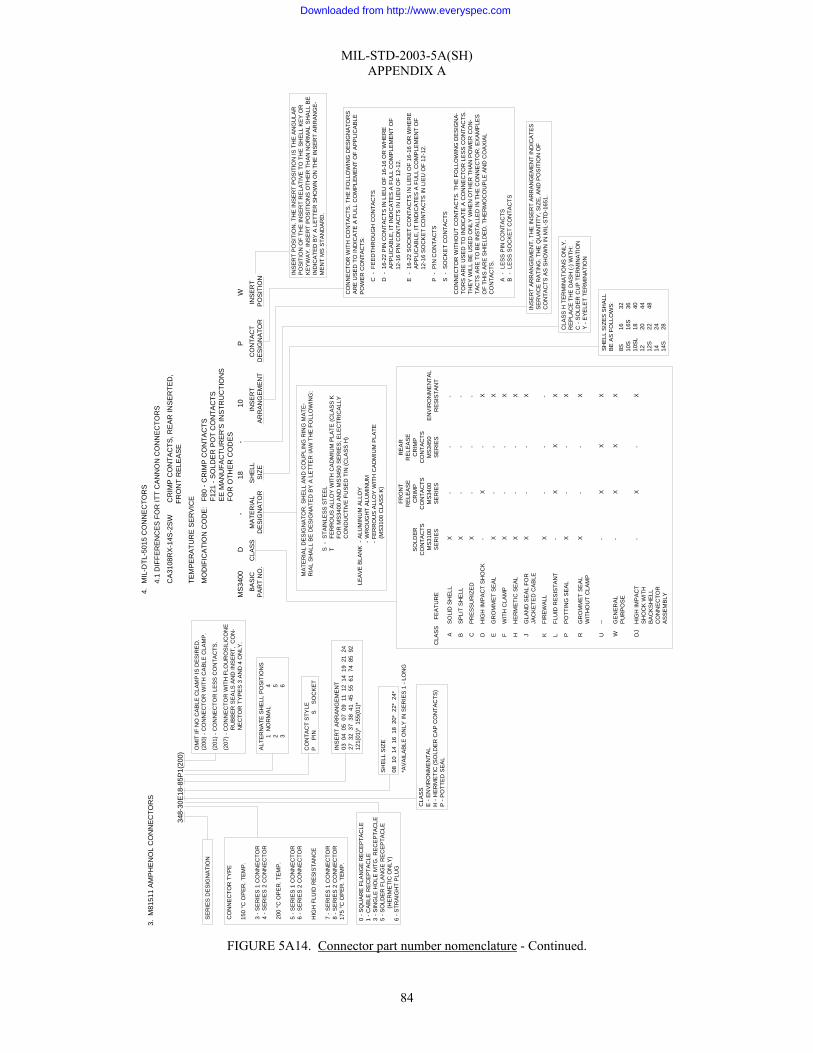
MIL-STD-2003-5A(SH) APPENDIX A
84
FIGURE 5A14. Connector part number nomenclature - Continued.
INS
ER
T A
RR
AN
GE
ME
NT.
TH
E IN
SE
RT
AR
RAN
GE
MEN
T IN
DIC
ATE
SS
ER
VIC
E R
ATI
NG
. TH
E Q
UA
NTI
TY, S
IZE
, AN
D P
OS
ITIO
N O
FC
ON
TAC
TS A
S S
HO
WN
IN M
IL-S
TD-1
651.
SE
RIE
S D
ESI
GN
ATIO
N
3. M
8151
1 A
MP
HE
NO
L C
ON
NE
CTO
RS
348-
30E
18-8
5P1(
200)
CO
NN
EC
TOR
TY
PE
150
°C O
PE
R. T
EMP
.
3 - S
ER
IES
1 C
ON
NEC
TOR
4 - S
ERIE
S 2
CO
NN
ECTO
R
200
°C O
PE
R. T
EM
P.
5 - S
ER
IES
1 C
ON
NEC
TOR
6 - S
ER
IES
2 C
ON
NEC
TOR
HIG
H F
LUID
RE
SIS
TAN
CE
7 - S
ER
IES
1 C
ON
NE
CTO
R8
- SE
RIE
S 2
CO
NN
ECTO
R17
5 °C
OP
ER
. TEM
P.
ALT
ERN
ATE
SH
ELL
PO
SIT
ION
S1
NO
RM
AL
42
53
6
INS
ER
T A
RR
AN
GE
ME
NT
03 0
4 0
5 0
7 0
9 1
1 1
2 1
4 1
9 2
1 2
427
32
37
38
41
45
55
61
74
85
92
121(
01)*
155
(01)
*
SH
ELL
SIZ
E
08 1
0 1
4 1
6 1
8 2
0* 2
2* 2
4**A
VAI
LABL
E O
NLY
IN S
ER
IES
1 -
LON
G
AS
OLI
D S
HEL
LX
--
-
BS
PLI
T S
HE
LLX
--
-
CP
RE
SS
UR
IZE
DX
--
-
DH
IGH
IMP
AC
T S
HO
CK
-X
-X
EG
RO
MM
ET
SEA
LX
--
X
FW
ITH
CLA
MP
X-
-X
HH
ER
ME
TIC
SE
AL
X-
-X
JG
LAN
D S
EA
L FO
RX
--
XJA
CK
ETE
D C
AB
LE
KFI
RE
WA
LLX
--
-
LFL
UID
RES
ISTA
NT
-X
XX
PP
OTT
ING
SEA
LX
--
X
RG
RO
MM
ET
SEA
LX
--
XW
ITH
OU
T C
LAM
P
U--
-X
XX
WG
EN
ERA
L-
XX
XP
UR
PO
SE
DJ
HIG
H IM
PA
CT
-X
-X
SH
OC
K W
ITH
BA
CKS
HE
LLC
ON
NE
CTO
RA
SSE
MB
LY
CO
NTA
CT
STY
LEP
PIN
SS
OC
KET
CLA
SS
FEA
TUR
E
INS
ER
T PO
SIT
ION
. TH
E IN
SE
RT
PO
SIT
ION
IS T
HE
AN
GU
LAR
PO
SIT
ION
OF
THE
INS
ER
T R
ELA
TIVE
TO
TH
E S
HE
LL K
EY
OR
KEY
WA
Y. I
NS
ER
T PO
SIT
ION
S O
THE
R T
HA
N N
OR
MA
L S
HA
LL B
EIN
DIC
ATE
D B
Y A
LE
TTE
R S
HO
WN
ON
TH
E IN
SER
T A
RR
ANG
E-
ME
NT
MS
STA
ND
AR
D.
CO
NN
EC
TOR
WIT
H C
ON
TAC
TS. T
HE
FO
LLO
WIN
G D
ESIG
NA
TOR
SA
RE
USE
D T
O IN
DIC
ATE
A F
ULL
CO
MP
LEM
EN
T O
F A
PP
LIC
ABL
EP
OW
ER
CO
NTA
CTS
:
C -
FEE
DTH
RO
UG
H C
ON
TAC
TS
D -
16-2
2 P
IN C
ON
TAC
TS IN
LIE
U O
F 16
-16
OR
WH
ER
EA
PP
LIC
AB
LE, I
T IN
DIC
ATE
S A
FU
LL C
OM
PLE
MEN
T O
F12
-16
PIN
CO
NTA
CTS
IN L
IEU
OF
12-1
2.
E -
16-2
2 S
OC
KET
CO
NTA
CTS
IN L
IEU
OF
16-1
6 O
R W
HE
RE
AP
PLI
CA
BLE
, IT
IND
ICA
TES
A F
ULL
CO
MPL
EM
ENT
OF
12-1
6 S
OC
KE
T C
ON
TAC
TS IN
LIE
U O
F 12
-12.
P -
PIN
CO
NTA
CTS
S -
SO
CK
ET
CO
NTA
CTS
CO
NN
EC
TOR
WIT
HO
UT
CO
NTA
CTS
. TH
E FO
LLO
WIN
G D
ES
IGN
A-
TOR
S A
RE
US
ED
TO
IND
ICA
TE A
CO
NN
EC
TOR
LE
SS
CO
NTA
CTS
.TH
EY
WIL
L B
E U
SED
ON
LY W
HE
N O
THE
R T
HA
N P
OW
ER
CO
N-
TAC
TS A
RE
TO
BE
INS
TALL
ED
IN T
HE
CO
NN
EC
TOR
. EX
AM
PLE
SO
F TH
IS A
RE
SH
IELD
ED
, TH
ER
MO
CO
UPL
E A
ND
CO
AXI
AL
CO
NTA
CTS
.
A -
LES
S P
IN C
ON
TAC
TSB
-LE
SS
SO
CK
ET
CO
NTA
CTS
SH
ELL
SIZ
ES S
HAL
LB
E A
S F
OLL
OW
S:
4.M
IL-D
TL-5
015
CO
NN
EC
TOR
S
4.1
DIF
FER
EN
CE
S F
OR
ITT
CA
NN
ON
CO
NN
EC
TOR
S
CA
3108
RX
-14S
-2S
W
C
RIM
P C
ON
TAC
TS, R
EA
R IN
SER
TED
,
FR
ON
T R
ELE
ASE
TEM
PE
RA
TUR
E S
ER
VIC
E
MO
DIF
ICA
TIO
N C
OD
E:F8
0 - C
RIM
P C
ON
TAC
TSF1
21 -
SO
LDE
R P
OT
CO
NTA
CTS
EE
MA
NU
FAC
TUR
ER'S
INS
TRU
CTI
ON
SFO
R O
THE
R C
OD
ES
MS
3400
D-
18-
10P
W
BASI
C
C
LASS
MA
TER
IAL
SH
ELL
IN
SER
T
CO
NTA
CT
I
NSE
RT
PAR
T N
O.
D
ESI
GN
ATO
R
S
IZE
A
RR
ANG
EME
NT
D
ESIG
NAT
OR
PO
SITI
ON
0 - S
QU
AR
E F
LAN
GE
RE
CE
PTA
CLE
1 - C
AB
LE R
ECE
PTA
CLE
3 - S
ING
LE H
OLE
MTG
. RE
CEP
TAC
LE5
- SO
LDE
R F
LAN
GE
RE
CEP
TAC
LE(H
ER
ME
TIC
ON
LY)
6 - S
TRAI
GH
T PL
UG
CLA
SSE
- E
NV
IRO
NM
EN
TAL
H -
HE
RM
ETI
C (S
OLD
ER
CA
P C
ON
TAC
TS)
P -
PO
TTE
D S
EAL
OM
IT IF
NO
CA
BLE
CLA
MP
IS D
ES
IRE
D.
(200
) - C
ON
NE
CTO
R W
ITH
CA
BLE
CLA
MP.
(201
) - C
ON
NE
CTO
R L
ESS
CO
NTA
CTS
.
(207
) - C
ON
NE
CTO
R W
ITH
FLO
UR
OS
ILIC
ON
E
R
UB
BE
R S
EA
LS A
ND
INS
ER
T, C
ON
-
N
EC
TOR
TY
PE
S 3
AN
D 4
ON
LY.
SO
LDER
CO
NTA
CTS
MS3
100
SER
IES
FRO
NT
RE
LEA
SE
CR
IMP
CO
NTA
CTS
MS
3400
SE
RIE
S
RE
AR
REL
EA
SEC
RIM
PC
ON
TAC
TSM
S345
0S
ERIE
SE
NV
IRO
NM
EN
TAL
RES
ISTA
NT
MAT
ER
IAL
DE
SIG
NA
TOR
. SH
ELL
AN
D C
OU
PLI
NG
RIN
G M
ATE-
RIA
L SH
ALL
BE
DE
SIG
NA
TED
BY
A L
ETT
ER
IAW
TH
E FO
LLO
WIN
G:
S -
STA
INLE
SS S
TEE
LT
FER
RO
US
ALL
OY
WIT
H C
AD
MIU
M P
LATE
(CLA
SS
KFO
R M
S34
00 A
ND
MS
3450
SE
RIE
S; E
LEC
TRIC
ALL
YC
ON
DU
CTI
VE
FU
SE
D T
IN (C
LAS
S H
)
LEAV
E B
LAN
K -
ALU
MIN
UM
ALL
OY
-W
RO
UG
HT
ALU
MIN
UM
- FE
RR
OU
S A
LLO
Y W
ITH
CA
DM
IUM
PLA
TE(M
S310
0 C
LAS
S K
)
8S16
3210
S16
S36
10S
L18
4012
2044
12S
2248
1424
14S
28CLA
SS H
TER
MIN
ATI
ON
S O
NLY
.R
EP
LAC
E T
HE
DAS
H (-
) WIT
H:
C -
SO
LDE
R C
UP
TER
MIN
ATI
ON
Y -
EY
ELE
T TE
RM
INA
TIO
N
Downloaded from http://www.everyspec.com

MIL-STD-2003-5A(SH) APPENDIX A
85
FIGURE 5A14. Connector part number nomenclature - Continued.
BAS
IC P
AR
T N
O.
4.2
BE
ND
IX 1
0-21
4 S
ER
IES
CO
NN
EC
TOR
10-2
14 6
- 14
- 6
P W
CLA
SS 0 - W
ALL
MO
UN
T R
EC
EP
TAC
LE
1 - C
ABLE
CO
NN
EC
TIN
G P
LUG
2 - B
OX
MO
UN
T R
EC
EP
TAC
LE
6 - S
TRAI
GH
T P
LUG
8 - 9
0 °
PLU
G
9 - 4
5 °
PLU
G
MAT
ER
IAL
DES
IGN
ATIO
N
S -
STA
INLE
SS
STE
EL
BLA
NK
- A
LUM
INU
M A
LLO
Y, W
RO
UG
HT
ALU
MIN
UM
AN
D
FER
RO
US
ALL
OY
SH
ELL
SIZ
E
INS
ER
T AR
RAN
GE
MEN
T
CO
NTA
CT
DE
SIG
NA
TOR
P -
PIN
S -
SO
CKE
T
ALT
ER
NA
TE IN
SE
RT
PO
SIT
ION
B
LAN
K -
NO
RM
AL
OR
W, X
, Y, Z
5. M
IL-D
TL-2
6482
CO
NN
EC
TOR
S
5.1
BEN
DIX
"PT"
CO
NN
EC
TOR
S
PT0
6 E
- 18
- 32
P W
BAS
IC S
HE
LL S
TYLE
PT0
0 - W
ALL
MO
UN
TIN
G
R
ECE
PTA
CLE
PT0
1 - C
AB
LE C
ON
NEC
TIN
G
PL
UG
PT0
2 - B
OX
MO
UN
TIN
G
R
ECE
PTA
CLE
PT0
6 - S
TRA
IGH
T P
LUG
PT0
7 - J
AM N
UT
REC
EPT
AC
LE
PT8
- TH
RU
-BU
LKH
EAD
REC
EPT
AC
LE
PT1
H -
SO
LDER
MO
UN
T
R
EC
EPTA
CLE
CLA
SS A -
GE
NER
AL
DU
TY
C -
PR
ES
SU
RIZ
ED
RE
CEP
TAC
LE
E -
EN
VIR
ON
ME
NTA
L
P -
PO
TTIN
G A
PPL
ICA
TIO
NS
W -
CAB
LE M
OIS
TUR
EPR
OO
FIN
G
H -
HER
ME
TIC
SEA
L R
EC
EP
TAC
LE
SH
ELL
SIZE
INS
ER
TA
RR
AN
GE
MEN
T
CO
NTA
CT
DE
SIG
NA
TOR
P -
PIN
S -
SO
CKE
T
ALT
ER
NA
TE IN
SER
T P
OSI
TIO
N
B
LAN
K - N
OR
MAL
OR
W
, X, Y
, Z
MS
3116
F -
20 -
16 P
W
MS
STA
ND
AR
DN
O.
CO
NN
EC
TOR
CLA
SS
AN
D S
ER
IES
SER
IES
1S
ER
IES
2 (1
25 °
C)
(200
°C
)FR
ON
T R
ELE
ASE
REA
R R
ELE
ASE
S
OLD
ER
CR
IMP
REM
OVA
BLE
S
OLD
ER
C
RIM
P R
EMO
VAB
LEC
LASS
CO
NTA
CTS
CO
NTA
CTS
A -
GR
OM
ME
T S
EAL,
NO
NC
ON
DU
CTI
VE
E -
GR
OM
ME
T S
EAL,
C
ON
DU
CTI
VE
P -
POTT
ED
SEA
L,
CO
ND
UC
TIV
EH
- H
ERM
ETI
C S
EAL,
C
ON
DU
CTI
VE
J - I
NS
ER
T SE
AL,
W
ITH
GLA
ND
SE
AL
FO
R J
AC
KETE
D
CA
BLE
,
CO
ND
UC
TIV
EL,
R -
FLU
ID
R
ES
ISTA
NT,
C
ON
DU
CTI
VE
N -
HER
ME
TIC
SEA
L
CR
IMP
TER
MIN
A-
T
ION
, CO
ND
UC
TIV
EF
- GR
OM
ME
T S
EAL
W
ITH
STR
AIN
R
ELI
EF
CLA
MP
C
ON
DU
CTI
VE
¹CLA
SS L
IS U
PGR
AD
ED
TO
200
°C
AN
D R
EP
LAC
ES C
LASS
E.
SE
RIE
S 2
, RE
AR
REL
EAS
E, C
RIM
P R
EM
OV
ABL
E C
ON
TAC
TS.
CLA
SS
R IS
INA
CTI
VE
FOR
NEW
DE
SIG
N.
X
XX
X
XX X X
X
X
X X
INSE
RT
PO
SIT
ION
. TH
E IN
SE
RT
PO
SIT
ION
IS T
HE
AN
GU
LAR
PO
SIT
ION
OF
THE
INS
ERT
RE
LATI
VE T
O T
HE
MA
STER
KE
Y O
RK
EYW
AY
OF
THE
SH
ELL
. IN
SER
T P
OS
ITIO
NS
OTH
ER
TH
AN N
OR
-M
AL S
HA
LL B
E IN
DIC
ATE
D B
Y T
HE
LE
TTER
SH
OW
N O
N T
HE
INSE
RT
AR
RA
NG
EME
NTS
SP
EC
IFIE
D B
Y M
IL-S
TD-1
669.
CO
NTA
CT
STYL
E. T
HE
FO
LLO
WIN
G D
ESI
GN
ATO
RS
AR
E U
SED
TO IN
DIC
ATE
A F
ULL
CO
MPL
IMEN
T O
F A
PP
LIC
ABL
E C
ON
TAC
TS.
P -
PIN
CO
NTA
CTS
S -
SOC
KET
CO
NTA
CTS
C -
FEE
DTH
RO
UG
H C
ON
TAC
TS
INS
ERT
ARR
AN
GEM
ENT.
TH
E IN
SE
RT
AR
RAN
GEM
EN
T S
HO
W-
ING
QU
AN
TITY
SIZ
E, S
ERV
ICE
RAT
ING
, AN
D P
OS
ITIO
NA
L LO
CA-
TIO
N O
F C
ON
TAC
TS S
HA
LL B
E A
S S
PEC
IFIE
D IN
MIL
-STD
-166
9.
SH
ELL
SIZ
E. S
HE
LL S
IZE
S S
HA
LL B
E A
S S
PEC
IFIE
D O
N T
HE
AP
PLIC
AB
LE M
S S
TAN
DA
RD
.
TER
MIN
ATI
ON
TY
PE A
ND
SH
ELL
MAT
ER
IAL
(HER
ME
TIC
RE
CE
P-TA
CLE
S O
NLY
). TH
E TY
PE
OF
TER
MIN
ATI
ON
AN
D S
HE
LL M
ATE-
RIA
L SH
ALL
BE
DE
SIG
NAT
ED A
S FO
LLO
WS:
TYP
E A
- S
OLD
ER
CU
P T
ER
MIN
ATI
ON
- ST
AIN
LES
S S
TEEL
S
HEL
L (S
ERIE
S 1)
.
TYP
E B
- E
YEL
ET T
ER
MIN
ATI
ON
- S
TAIN
LES
S S
TEE
L
SH
ELL
(SER
IES
1).
TYP
E C
- S
OLD
ER
CU
P T
ER
MIN
ATI
ON
- FE
RR
OU
S A
LLO
Y
SH
ELL
(SER
IES
1 A
ND
2).
TYP
E D
- C
RIM
P TE
RM
INAT
ION
- FE
RR
OU
S AL
LOY
SH
ELL
(S
ER
IES
2).
TYP
E Y
- E
YEL
ET T
ER
MIN
ATI
ON
- FE
RR
OU
S A
LLO
Y S
HE
LL
(SE
RIE
S 2
).
Downloaded from http://www.everyspec.com
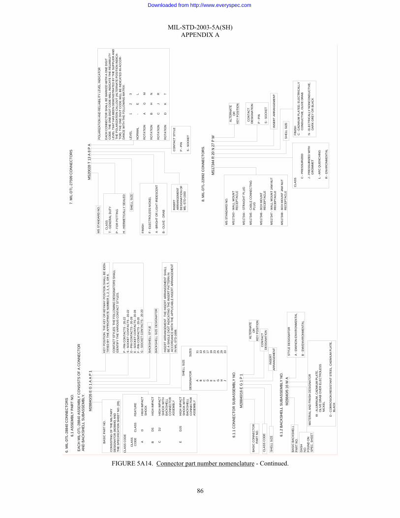
MIL-STD-2003-5A(SH) APPENDIX A
86
FIGURE 5A14. Connector part number nomenclature - Continued.
BA
SIC
PA
RT
NO
.
CO
NS
ISTI
NG
OF
THE
MIL
ITAR
YD
ES
IGN
ATO
R (M
2884
0) A
ND
THE
SP
EC
IFIC
ATI
ON
SH
EE
T N
O. (
26).
6. M
IL-D
TL-2
8840
CO
NN
EC
TOR
S
M28
840/
26 E
G 1
A A
P 1
6.1
AS
SE
MB
LY P
AR
T N
O.
EA
CH
MIL
-DTL
-288
40 A
SS
EM
BLY
CO
NS
ISTS
OF
A C
ON
NE
CTO
RA
ND
BA
CK
SH
ELL
SU
BA
SS
EM
BLY
.
CLA
SS
CO
DE
CLA
SS
CO
DE
CLA
SS
FE
ATU
RE
A
D
HIG
H IM
PAC
T
S
HO
CK
B
D
S
HIG
H IM
PA
CT
C
DJ
HIG
H IM
PAC
T
S
HO
CK
WIT
H
B
AC
KS
HE
LL
C
ON
NE
CTO
R
A
SS
EM
BLY
E
D
JS
H
IGH
IMP
AC
T
SH
OC
K W
ITH
BA
CK
SH
ELL
CO
NN
EC
TOR
AS
SE
MB
LY
SH
ELL
SIZ
E
DE
SIG
NA
TOR
SIZ
ES
A
11
B
13
C
15
D
17
E
19
F
23
G
25
H
29
J
33KE
Y P
OS
ITIO
N. T
HE
KEY
OR
KE
YW
AY
PO
SIT
ION
SH
ALL
BE
IDE
N-
TIFI
ED
BY
TH
E A
PP
RO
PR
IATE
NU
MB
ER
1, 2
, 3, 4
, 5, O
R 6
.
CO
NTA
CT
STY
LES
. TH
E F
OLL
OW
ING
DES
IGN
ATO
RS
SHA
LLID
EN
TIFY
TH
E V
AR
IOU
S C
ON
TAC
T S
TYLE
S.
P -
PIN
CO
NTA
CTS
- 20
-22
S -
SO
CK
ET
CO
NTA
CTS
- 20
-22
D -
PIN
CO
NTA
CTS
- 20
-28
E -
SO
CK
ET
CO
NTA
CTS
- 20
-28
F - P
IN C
ON
TAC
TS -
20-2
0G
- S
OC
KE
T C
ON
TAC
TS -
20-2
0
BA
CK
SH
ELL
STY
LE
BA
CK
SH
ELL
SIZ
E D
ES
IGN
ATO
R
INS
ER
T A
RR
AN
GE
ME
NT.
TH
E IN
SE
RT
AR
RA
NG
EM
EN
T S
HA
LLB
E A
SIN
GLE
DIG
IT IN
DIC
ATI
NG
TH
E IN
SER
T P
ATTE
RN
INA
CC
OR
DA
NC
E W
ITH
TH
E A
PP
LIC
AB
LE IN
SE
RT
AR
RAN
GE
ME
NT
IN M
IL-S
TD-1
698.
MS
2002
8 T
13 A
8 P
A
7. M
IL-D
TL-2
7599
CO
NN
EC
TOR
S
MS
STA
ND
AR
D N
O.
C
LAS
ST
- GE
NE
RA
L D
UTY
P -
FOR
PO
TTIN
G
H -
HE
RM
ETI
CA
LLY
SE
ALE
D
SH
ELL
SIZ
E
FIN
ISH
F - E
LEC
TRO
LES
S N
ICK
EL
A -
BR
IGH
T O
R L
IGH
T IR
IDE
SC
EN
T
B -
OLI
VE
- D
RA
B INS
ERT
AR
RA
NG
EM
ENT
DE
SIG
NA
TIO
N O
FM
IL-S
TD-1
560
CO
NTA
CT
STY
LE
P -
PIN
S -
SOC
KE
T
PO
LAR
IZA
TIO
N A
ND
RE
LIA
BIL
ITY
LE
VE
L IN
DIC
ATO
R
EAC
H C
ON
NE
CTO
R S
HAL
L B
E M
AR
KE
D W
ITH
A O
NE
DIG
ITC
OD
E. T
HE
ON
E D
IGIT
CO
DE
WIL
L IN
DIC
ATE
TH
E R
ELI
AB
ILIT
YLE
VE
L TH
AT
HA
S B
EEN
DE
MO
NS
TRA
TED
BY
THE
SU
PP
LIE
R A
ND
THE
PO
LAR
IZA
TIO
N C
ALL
OU
T (A
LTER
NA
TE P
OS
ITIO
N IN
DIC
A-
TOR
). TH
E O
NE
DIG
IT C
OD
E W
ILL
BE
IND
ICA
TED
IN A
CC
OR
-D
AN
CE
WIT
H T
HE
FO
LLO
WIN
G M
ATR
IX:
LEV
EL
1 2
3
NO
RM
AL
- E
L
RO
TATI
ON
A G
M
RO
TATI
ON
B H
N
RO
TATI
ON
C J
R
RO
TATI
ON
D K
T
6.1.
1 C
ON
NE
CTO
R S
UB
AS
SE
MB
LY N
O.
M28
840/
16 E
G 1
P 1
BA
SIC
CO
NN
EC
TOR
PA
RT
NO
.
CLA
SS
CO
DE
SH
ELL
SIZ
E
ALT
ER
NAT
EO
RK
EY
PO
SIT
ION
CO
NTA
CT
DE
SIG
NA
TIO
NIN
SE
RT
AR
RA
NG
EM
EN
T
6.1.
2 B
AC
KS
HE
LL S
UB
AS
SE
MB
LY N
O.
M28
840/
6 16
W A
BA
SIC
BAC
KSH
ELL
PA
RT
NO
.
DA
SH
NO
.FO
UN
D O
NS
PE
C. S
HE
ET
MA
TER
IAL
AN
D F
INIS
H D
ES
IGN
ATO
R
W -
ALU
MIN
UM
, CAD
MIU
M P
LATE
,
O
LIVE
DR
AB
OV
ER
ELE
CTR
OLE
SS
NIC
KEL
D -
CO
RR
OS
ION
RE
SIS
TAN
T S
TEE
L, C
ADM
IUM
PLA
TE,
BLA
CK
STY
LE D
ES
IGN
ATO
R
A -
EM
I/NO
N-E
NV
IRO
NM
EN
TAL
B -
EM
I/EN
VIR
ON
ME
NTA
L
8. M
IL-D
TL-2
2992
CO
NN
EC
TOR
S.
MS
1734
4 R
20
N 2
7 P
W
MS
STA
ND
AR
D N
O.
MS
1734
3 - W
ALL
MO
UN
T
R
EC
EP
TAC
LE
MS
1734
4 - S
TRA
IGH
T P
LUG
MS
1734
5 - C
AB
LE C
ON
NE
CTI
NG
PLU
G
MS
1734
6 - B
OX
MO
UN
T
R
EC
EP
TAC
LE
MS
1734
7 - W
ALL
MO
UN
T JA
M N
UT
RE
CE
PTA
CLE
MS
1734
8 - B
OX
MO
UN
T JA
M N
UT
RE
CE
PTA
CLE
CLA
SS C
- P
RE
SS
UR
IZE
D
J - P
RE
SSU
RIZ
ED W
ITH
G
RO
MM
ET
L - A
RC
QU
EN
CH
ING
R -
EN
VIR
ON
ME
NTA
L
FIN
ISH
C -
CA
DM
IUM
PLA
TED
, ELE
CTR
ICA
LLY
CO
ND
UC
TIV
E, O
LIV
E D
RA
B
N -
ELE
CTR
ICA
LLY
NO
NC
ON
DU
CTI
VE
,
D
AR
K G
RE
Y O
R B
LAC
K
SH
ELL
SIZ
E
INS
ER
T A
RR
AN
GE
ME
NT
CO
NTA
CT
DE
SIG
NA
TIO
N
P -
PIN
S -
SO
CK
ET
ALT
ER
NAT
EO
RK
EY
PO
SIT
ION
Downloaded from http://www.everyspec.com

MIL-STD-2003-5A(SH) APPENDIX A
87
FIGURE 5A14. Connector part number nomenclature - Continued.
MS
STA
ND
ARD
NO
.
9. M
IL-D
TL-3
8999
CO
NN
ECTO
RS
MS
2746
7 T
13 F
8 P
A
9.1
SE
RIE
S I
AN
D II
CLA
SS
E -
ENV
IRO
NM
EN
TAL
P -
FOR
PO
TTIN
G
T - E
NV
IRO
NM
EN
TAL
W/O
R
EA
R A
CC
ES
OR
IES
Y -
HE
RM
ETI
CA
LLY
SEA
LED
SH
ELL
SIZ
E
FIN
ISH
ES
-
A -
BR
IGH
T C
AD
MIU
M P
LATE
OV
ER N
ICKE
L (C
ON
DU
C-
TIVE
)
(INAC
TIV
E F
OR
NE
W D
ESI
GN
)B
- O
LIVE
-DR
AB
CA
DM
IUM
PLA
TE O
VER
SU
ITAB
LE
U
ND
ER
PLA
TE (C
ON
DU
CTI
VE)
C -
AN
OD
IC (N
ON
CO
ND
UC
TIV
E)D
- FU
SE
D T
IN, C
AR
BO
N S
TEEL
(CO
ND
UC
TIV
E)E
- C
OR
RO
SIO
N R
ES
ISTA
NT
STE
EL, P
ASS
IVAT
ED (C
ON
-
D
UC
TIV
E)
F - E
LEC
TRO
LES
S N
ICK
EL C
OAT
ING
(CO
ND
UC
TIV
E)
04
9H -
HER
ME
TIC
SEA
L O
R E
NVI
RO
NM
ENTA
L R
ESIS
TIN
G
C
OR
RIS
ION
RES
ISTA
NT
STE
EL
(CO
ND
UC
TIVE
PLA
TIN
G)
INS
ER
T AR
RAN
GE
MEN
T
CO
NTA
CT
STY
LES:
(1) C
ON
NE
CTO
RS
OR
DE
RED
WIT
H C
ON
TAC
TS:
P -
PIN
- IN
CLU
DIN
G H
ER
MET
ICS
WIT
H S
OLD
ER C
UP
S.S
- S
OC
KE
T - I
NC
LUD
ING
HE
RM
ETIC
S W
ITH
SO
LDE
R C
UPS
.X
- P
IN -
WIT
H E
YEL
ET (H
ER
MET
IC)
Z - S
OC
KET
- WIT
H E
YELE
T (H
ER
ME
TIC
)C
- FE
ED
THR
OU
GH
(2) C
ON
NE
CTO
RS
OR
DE
RED
WIT
HO
UT
CO
NTA
CTS
:
A -
LES
S P
IN C
ON
TAC
TSB
- LE
SS
SOC
KE
T C
ON
TAC
TS
PO
LAR
IZAT
ION
OR
ALT
ER
NA
TE P
OS
ITIO
NB
LAN
K -
NO
RM
AL
9.2
SE
RIE
S II
I AN
D IV
D38
999/
20 F
J 3
0 P
N
SP
ECIF
ICA
TIO
N S
HE
ET N
O.
CLA
SS
C -
EN
VIR
ON
ME
NTA
L, N
ON
CO
ND
UC
TIVE
PLAT
ING
F - E
NV
IRO
NM
EN
TAL,
CO
ND
UC
TIV
E
PLA
TIN
G
K -
EN
VIR
ON
ME
NTA
L, C
OR
RO
SIO
N
R
ES
ISTA
NT
STE
EL W
ITH
FIR
EW
ALL
BA
RR
IER
W -
EN
VIR
ON
ME
NTA
L, C
OR
RO
SIO
N R
ESIS
TAN
T
P
LATI
NG
Y -
HE
RM
ETI
CA
LLY
SE
ALED
CO
RR
OSI
ON
RE
SIS
TAN
T ST
EEL
N -
HER
ME
TIC
ALL
Y S
EAL
ED, C
OR
RO
SIO
N
R
ES
ISTA
NT
STE
EL, E
LEC
TRO
DEP
OS
ITE
D N
ICKE
L
N -
(CLA
SS
III) E
NV
IRO
NM
EN
TAL
WIT
H
FIR
EW
ALL
BAR
RIE
R C
OR
RO
SIO
N R
ES
ISTA
NT
S
TEE
L, E
LEC
TRO
DE
POS
ITE
D N
ICKE
L
S
HE
LL S
IZE
CO
DE
SH
ELL
LETT
ER S
IZE
A
9
B
1
1
C
1
3
D
1
5
E
1
7
F
1
9
G
2
1
H
2
3
J
2
5
INS
ERT
AR
RA
NG
EME
NT
CO
NTA
CT
STY
LE(S
EE
SER
IES
I AN
D II
)
PO
LAR
IZAT
ION
OR
ALT
ER
NA
TEP
OS
ITIO
N
Downloaded from http://www.everyspec.com

MIL-STD-2003-5A(SH) APPENDIX B
88
GROUP 5B - MIL-C-81511 SERIES 1 AND 2 GANG CONTACT RELEASE CONNECTOR ASSEMBLY PROCEDURE
B.1 SCOPE
B.1.1 Scope. This appendix describes procedures for the preparation of MIL-C-81511 Series 1 and 2 gang connector assembly.
B.2 APPLICABLE DOCUMENTS
B.2.1 General. The documents listed in this section are specified in this appendix. This section does not include documents cited in other sections of this standard or recommended for additional information or as examples. While every effort has been made to ensure the completeness of this list, document users are cautioned that they must meet all specified requirements of documents cited in this appendix, whether or not they are listed.
B.2.2 Government documents.
B.2.2.1 Specifications, standards, and handbooks. The following specifications, standards, and handbooks form a part of this document to the extent specified herein. Unless otherwise specified, the issues of these documents are those cited in the solicitation or contract.
DEPARTMENT OF DEFENSE SPECIFICATIONS
MIL-C-81511 - Connectors, Electrical, Circular, High Density, Quick Disconnect, Environment Resisting: and Accessories, General Specification for
MIL-C-81511/5 - Connectors, Electrical, Circular, High Density, Quick Disconnect, Environment Resisting; and Accessories: Receptacle, Cable Connecting, Crimp-Type Contacts, Class A, F and E (Series 2)
MIL-C-81511/6 - Connectors, Electrical, Circular, High Density, Quick Disconnect, Environment Resisting; and Accessories: Plug, Crimp-Type Contacts, Class A, F and E (Series 2)
MIL-C-81511/15 - Connectors, Electrical, Circular, High Density, Quick Disconnect, Environment Resisting; and Accessories: Plug, Sealing Contact (Series 1 or 2)
MIL-C-81511/25 - Connectors, Electrical, Circular, High Density, Quick Disconnect, Environment Resisting; and Accessories: Receptacle, Cable Connecting, Crimp-Type Contacts Class A, F and E (Series 1)
MIL-C-81511/26 - Connectors, Electrical, Circular, High Density, Quick Disconnect, Environment Resisting; and Accessories: Plug, Crimp-Type Contacts, Class A, F and E (Series 1)
MIL-C-81511/45 - Connectors, Electrical, Circular, High Density, Quick Disconnect, Environment Resisting: Receptacle, Cable Connecting, Individual Release, Crimp-Type Contacts, Class A, F and W (Series 3)
MIL-C-81511/46 - Connectors, Electrical, Circular, High Density, Quick Disconnect, Environment Resisting: Plug, Individual, Release, Crimp-Type Contacts, Class A, F and W (Series 3)
MIL-C-81511/55 - Connectors, Electrical, Circular, High Density, Quick Disconnect, Environment Resisting: Receptacle, Cable Connecting, Individual Release, Crimp-Type Contacts, Class A, F and W (Series 4)
Downloaded from http://www.everyspec.com
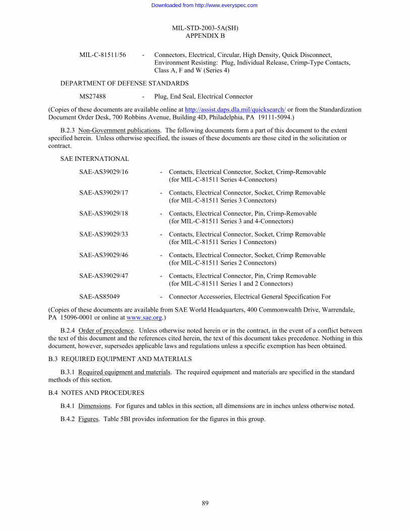
MIL-STD-2003-5A(SH) APPENDIX B
89
MIL-C-81511/56 - Connectors, Electrical, Circular, High Density, Quick Disconnect, Environment Resisting: Plug, Individual Release, Crimp-Type Contacts, Class A, F and W (Series 4)
DEPARTMENT OF DEFENSE STANDARDS
MS27488 - Plug, End Seal, Electrical Connector
(Copies of these documents are available online at http://assist.daps.dla.mil/quicksearch/ or from the Standardization Document Order Desk, 700 Robbins Avenue, Building 4D, Philadelphia, PA 19111-5094.)
B.2.3 Non-Government publications. The following documents form a part of this document to the extent specified herein. Unless otherwise specified, the issues of these documents are those cited in the solicitation or contract.
SAE INTERNATIONAL
SAE-AS39029/16 - Contacts, Electrical Connector, Socket, Crimp-Removable (for MIL-C-81511 Series 4-Connectors)
SAE-AS39029/17 - Contacts, Electrical Connector, Socket, Crimp Removable (for MIL-C-81511 Series 3 Connectors)
SAE-AS39029/18 - Contacts, Electrical Connector, Pin, Crimp-Removable (for MIL-C-81511 Series 3 and 4-Connectors)
SAE-AS39029/33 - Contacts, Electrical Connector, Socket, Crimp Removable (for MIL-C-81511 Series 1 Connectors)
SAE-AS39029/46 - Contacts, Electrical Connector, Socket, Crimp Removable (for MIL-C-81511 Series 2 Connectors)
SAE-AS39029/47 - Contacts, Electrical Connector, Pin, Crimp Removable (for MIL-C-81511 Series 1 and 2 Connectors)
SAE-AS85049 - Connector Accessories, Electrical General Specification For
(Copies of these documents are available from SAE World Headquarters, 400 Commonwealth Drive, Warrendale, PA 15096-0001 or online at www.sae.org.)
B.2.4 Order of precedence. Unless otherwise noted herein or in the contract, in the event of a conflict between the text of this document and the references cited herein, the text of this document takes precedence. Nothing in this document, however, supersedes applicable laws and regulations unless a specific exemption has been obtained.
B.3 REQUIRED EQUIPMENT AND MATERIALS
B.3.1 Required equipment and materials. The required equipment and materials are specified in the standard methods of this section.
B.4 NOTES AND PROCEDURES
B.4.1 Dimensions. For figures and tables in this section, all dimensions are in inches unless otherwise noted.
B.4.2 Figures. Table 5BI provides information for the figures in this group.
Downloaded from http://www.everyspec.com

MIL-STD-2003-5A(SH) APPENDIX B
90
TABLE 5BI. Figures for MIL-C-81511 connector assembly preparation.
Figure number MIL-C-81511 connector assembly procedures Page
5B1 MIL-C-81511 series 1 and 2 gang contact release connector assembly procedure 91 5B2 MIL-C-81511 series 3 and 4 individual contact release connector assembly procedure 103
Downloaded from http://www.everyspec.com
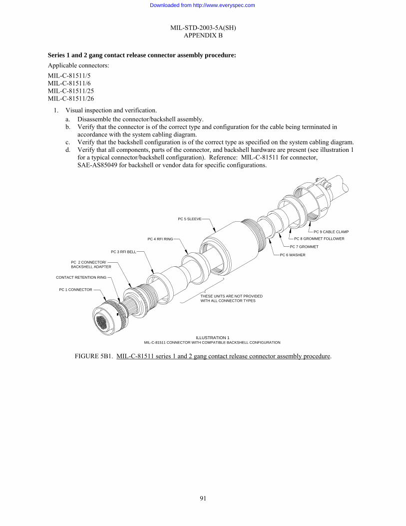
MIL-STD-2003-5A(SH) APPENDIX B
91
Series 1 and 2 gang contact release connector assembly procedure: Applicable connectors: MIL-C-81511/5 MIL-C-81511/6 MIL-C-81511/25 MIL-C-81511/26
1. Visual inspection and verification. a. Disassemble the connector/backshell assembly. b. Verify that the connector is of the correct type and configuration for the cable being terminated in
accordance with the system cabling diagram. c. Verify that the backshell configuration is of the correct type as specified on the system cabling diagram. d. Verify that all components, parts of the connector, and backshell hardware are present (see illustration 1
for a typical connector/backshell configuration). Reference: MIL-C-81511 for connector, SAE-AS85049 for backshell or vendor data for specific configurations.
FIGURE 5B1. MIL-C-81511 series 1 and 2 gang contact release connector assembly procedure.
ILLUSTRATION 1MIL-C-81511 CONNECTOR WITH COMPATIBLE BACKSHELL CONFIGURATION
PC 1 CONNECTOR
CONTACT RETENTION RING
PC 2 CONNECTOR/BACKSHELL ADAPTER
PC 3 RFI BELL
PC 4 RFI RING
PC 5 SLEEVE
PC 9 CABLE CLAMP
PC 8 GROMMET FOLLOWER
PC 7 GROMMET
PC 6 WASHER
THESE UNITS ARE NOT PROVIDEDWITH ALL CONNECTOR TYPES
Downloaded from http://www.everyspec.com
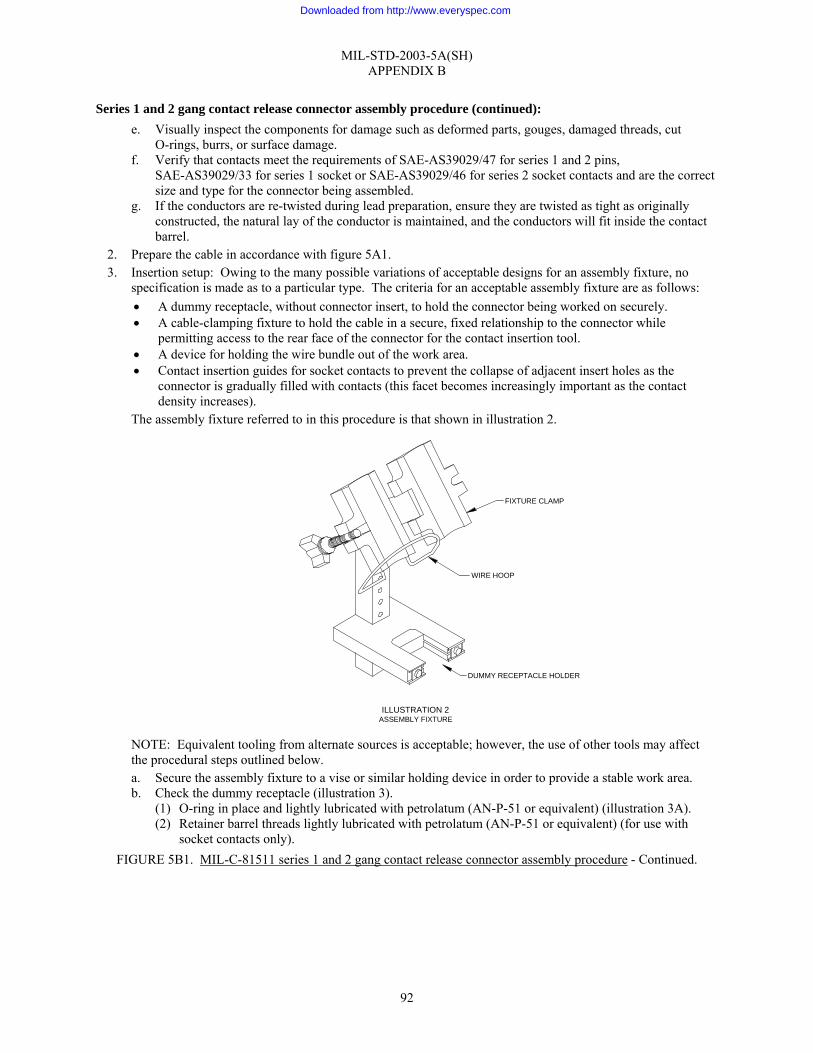
MIL-STD-2003-5A(SH) APPENDIX B
92
Series 1 and 2 gang contact release connector assembly procedure (continued): e. Visually inspect the components for damage such as deformed parts, gouges, damaged threads, cut
O-rings, burrs, or surface damage. f. Verify that contacts meet the requirements of SAE-AS39029/47 for series 1 and 2 pins,
SAE-AS39029/33 for series 1 socket or SAE-AS39029/46 for series 2 socket contacts and are the correct size and type for the connector being assembled.
g. If the conductors are re-twisted during lead preparation, ensure they are twisted as tight as originally constructed, the natural lay of the conductor is maintained, and the conductors will fit inside the contact barrel.
2. Prepare the cable in accordance with figure 5A1. 3. Insertion setup: Owing to the many possible variations of acceptable designs for an assembly fixture, no
specification is made as to a particular type. The criteria for an acceptable assembly fixture are as follows: • A dummy receptacle, without connector insert, to hold the connector being worked on securely. • A cable-clamping fixture to hold the cable in a secure, fixed relationship to the connector while
permitting access to the rear face of the connector for the contact insertion tool. • A device for holding the wire bundle out of the work area. • Contact insertion guides for socket contacts to prevent the collapse of adjacent insert holes as the
connector is gradually filled with contacts (this facet becomes increasingly important as the contact density increases).
The assembly fixture referred to in this procedure is that shown in illustration 2.
NOTE: Equivalent tooling from alternate sources is acceptable; however, the use of other tools may affect the procedural steps outlined below. a. Secure the assembly fixture to a vise or similar holding device in order to provide a stable work area. b. Check the dummy receptacle (illustration 3).
(1) O-ring in place and lightly lubricated with petrolatum (AN-P-51 or equivalent) (illustration 3A). (2) Retainer barrel threads lightly lubricated with petrolatum (AN-P-51 or equivalent) (for use with
socket contacts only). FIGURE 5B1. MIL-C-81511 series 1 and 2 gang contact release connector assembly procedure - Continued.
DUMMY RECEPTACLE HOLDER
WIRE HOOP
FIXTURE CLAMP
ILLUSTRATION 2ASSEMBLY FIXTURE
Downloaded from http://www.everyspec.com

MIL-STD-2003-5A(SH) APPENDIX B
93
Series 1 and 2 gang contact release connector assembly procedure (continued): (3) All guide pins present and straight (for use with socket contacts only). (4) Guide pins pressed back into the dummy receptacle so that no more than ⅛" projects (for use with
socket contacts only). c. Mate the connector to the dummy receptacle/retainer barrel (if required) assembly, and lock the coupling
ring (illustration 3B). d. Turn the contact retention ring clockwise to the locked position (illustration 3C).
FIGURE 5B1. MIL-C-81511 series 1 and 2 gang contact release connector assembly procedure - Continued.
3A
MATE CONNECTOR TODUMMY RECEPTACLE
MASTER KEYING STRIPE
TURN CONNECTORCOUPLING CLOCKWISE
ILLUSTRATION 3DUMMY RECEPTACLE
"O" RING
3C
TURN RETENTIONRING CLOCKWISE
3D
PUSH PLUNGER UP
GUIDE PINSPROTRUDE 1/8"
3B
Downloaded from http://www.everyspec.com
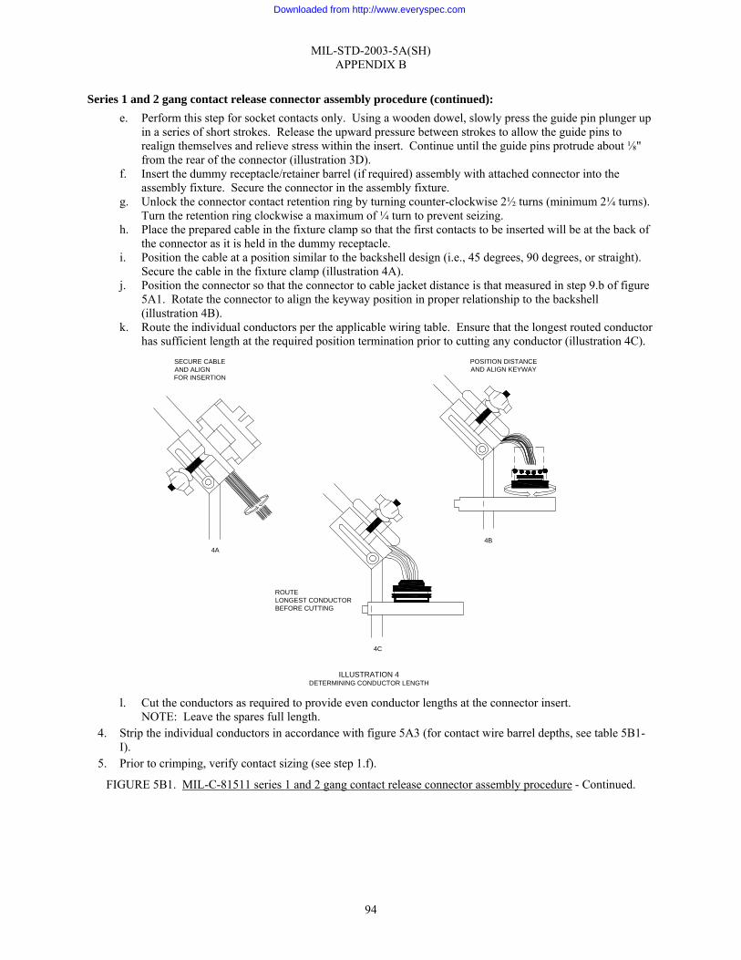
MIL-STD-2003-5A(SH) APPENDIX B
94
Series 1 and 2 gang contact release connector assembly procedure (continued): e. Perform this step for socket contacts only. Using a wooden dowel, slowly press the guide pin plunger up
in a series of short strokes. Release the upward pressure between strokes to allow the guide pins to realign themselves and relieve stress within the insert. Continue until the guide pins protrude about ⅛" from the rear of the connector (illustration 3D).
f. Insert the dummy receptacle/retainer barrel (if required) assembly with attached connector into the assembly fixture. Secure the connector in the assembly fixture.
g. Unlock the connector contact retention ring by turning counter-clockwise 2½ turns (minimum 2¼ turns). Turn the retention ring clockwise a maximum of ¼ turn to prevent seizing.
h. Place the prepared cable in the fixture clamp so that the first contacts to be inserted will be at the back of the connector as it is held in the dummy receptacle.
i. Position the cable at a position similar to the backshell design (i.e., 45 degrees, 90 degrees, or straight). Secure the cable in the fixture clamp (illustration 4A).
j. Position the connector so that the connector to cable jacket distance is that measured in step 9.b of figure 5A1. Rotate the connector to align the keyway position in proper relationship to the backshell (illustration 4B).
k. Route the individual conductors per the applicable wiring table. Ensure that the longest routed conductor has sufficient length at the required position termination prior to cutting any conductor (illustration 4C).
l. Cut the conductors as required to provide even conductor lengths at the connector insert.
NOTE: Leave the spares full length. 4. Strip the individual conductors in accordance with figure 5A3 (for contact wire barrel depths, see table 5B1-
I). 5. Prior to crimping, verify contact sizing (see step 1.f).
FIGURE 5B1. MIL-C-81511 series 1 and 2 gang contact release connector assembly procedure - Continued.
SECURE CABLEAND ALIGNFOR INSERTION
4A
POSITION DISTANCEAND ALIGN KEYWAY
4B
ROUTELONGEST CONDUCTORBEFORE CUTTING
4C
ILLUSTRATION 4DETERMINING CONDUCTOR LENGTH
Downloaded from http://www.everyspec.com

MIL-STD-2003-5A(SH) APPENDIX B
95
TABLE 5B1-I. Wire barrel depths and minimum separation force.
Wire barrel depth (inch) Minimum separation force (oz.)
Series 1 Series 2 Series 1 &2 Contact size
Pin Socket Pin Socket Socket
12-12 0.276-0.296 0.276-0.296 0.276-0.296 0.276-0.296 2.5 16-16 0.266-0.286 0.266-0.286 0.266-0.286 0.266-0.286 1.5 20-20 0.256-0.276 0.256-0.276 0.256-0.276 0.256-0.276 0.6 23-22 0.215-0.235 0.215-0.235 0.215-0.235 0.215-0.235 0.4 23-28 0.215-0.235 0.215-0.235 0.215-0.235 0.215-0.235 0.4
Series 1 and 2 gang contact release connector assembly procedure (continued):
6. Terminate individual conductors with crimp contacts in accordance with figure 5A4 (see table 5B1-II for proper crimping tool). If contact rework shortens a conductor’s initial length by greater than ¼", the jacket must be cut back again and all conductors re-trimmed to preclude stress.
TABLE 5B1-II. Crimp tooling information.
Series 1 & 2 pins and series 2 socket Series 1 socket Contact size
Crimping tool Positioner Crimping tool Positioner
12-12 M22520/1-01 M22520/1-08 Yellow M22520/1-01 M22520/1-08 Yellow M22520/7-01 M22520/7-10 16-16 M22520/1-01 M22520/1-08 Blue
M22520/1-01 M22520/1-08 Blue
M22520/7-01 M22520/7-09 20-20 M22520/1-01 M22520/1-08 Red
M22520/1-01 M22520/1-08 Red
23-22 M22520/2-01 M22520/2-03 M22520/2-01 M22520/2-03 23-28 M22520/2-01 M22520/2-03 M22520/2-01 M22520/2-03
a. Secure the wire bundle in the wire hoop so that the work area at the connector face is clear.
7. Inserting contacts: a. Using the proper wiring table, proper inserting tool based on contact type (see table 5B1-III), and
working from the rear to the front of the insertion fixture, insert the contacts into their designated locations in the connector as follows:
FIGURE 5B1. MIL-C-81511 series 1 and 2 gang contact release connector assembly procedure - Continued.
Downloaded from http://www.everyspec.com
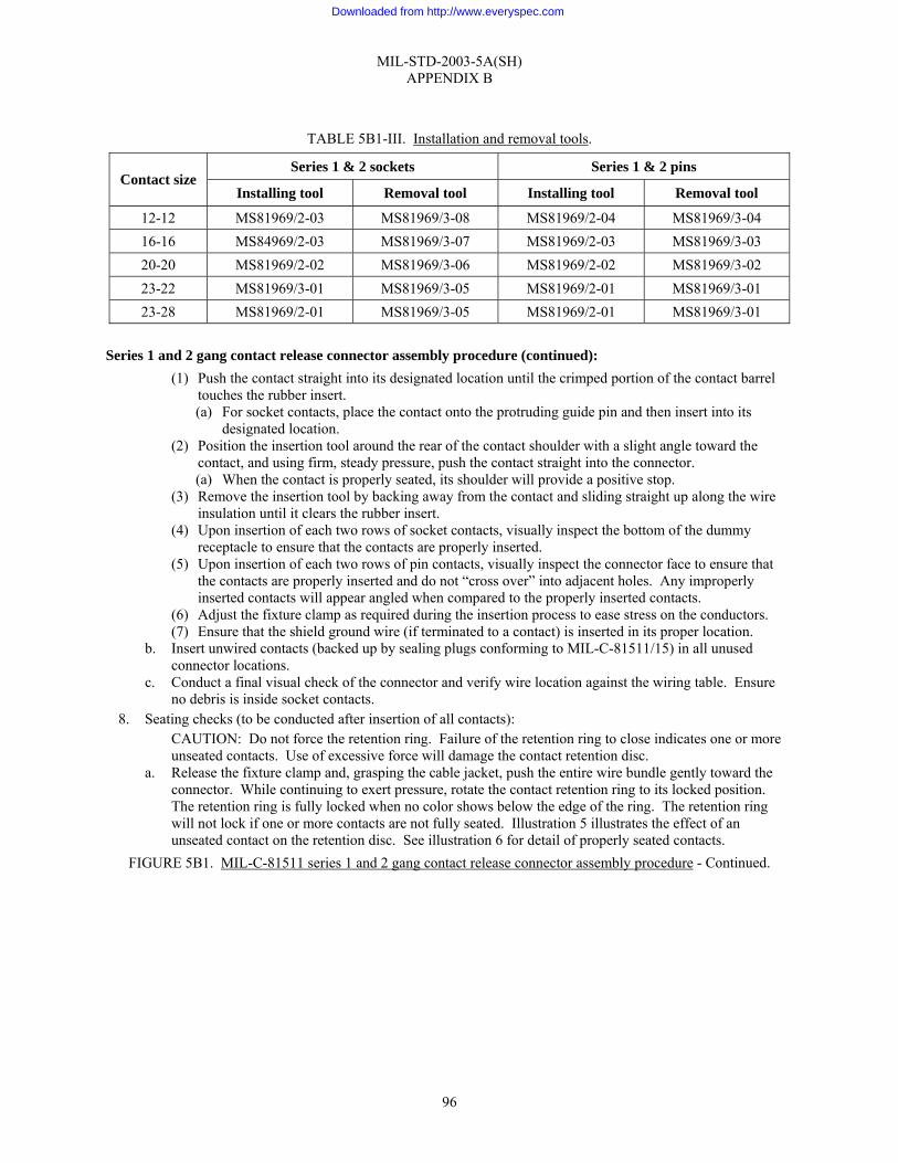
MIL-STD-2003-5A(SH) APPENDIX B
96
TABLE 5B1-III. Installation and removal tools.
Series 1 & 2 sockets Series 1 & 2 pins Contact size
Installing tool Removal tool Installing tool Removal tool
12-12 MS81969/2-03 MS81969/3-08 MS81969/2-04 MS81969/3-04 16-16 MS84969/2-03 MS81969/3-07 MS81969/2-03 MS81969/3-03 20-20 MS81969/2-02 MS81969/3-06 MS81969/2-02 MS81969/3-02 23-22 MS81969/3-01 MS81969/3-05 MS81969/2-01 MS81969/3-01 23-28 MS81969/2-01 MS81969/3-05 MS81969/2-01 MS81969/3-01
Series 1 and 2 gang contact release connector assembly procedure (continued):
(1) Push the contact straight into its designated location until the crimped portion of the contact barrel touches the rubber insert. (a) For socket contacts, place the contact onto the protruding guide pin and then insert into its
designated location. (2) Position the insertion tool around the rear of the contact shoulder with a slight angle toward the
contact, and using firm, steady pressure, push the contact straight into the connector. (a) When the contact is properly seated, its shoulder will provide a positive stop.
(3) Remove the insertion tool by backing away from the contact and sliding straight up along the wire insulation until it clears the rubber insert.
(4) Upon insertion of each two rows of socket contacts, visually inspect the bottom of the dummy receptacle to ensure that the contacts are properly inserted.
(5) Upon insertion of each two rows of pin contacts, visually inspect the connector face to ensure that the contacts are properly inserted and do not “cross over” into adjacent holes. Any improperly inserted contacts will appear angled when compared to the properly inserted contacts.
(6) Adjust the fixture clamp as required during the insertion process to ease stress on the conductors. (7) Ensure that the shield ground wire (if terminated to a contact) is inserted in its proper location.
b. Insert unwired contacts (backed up by sealing plugs conforming to MIL-C-81511/15) in all unused connector locations.
c. Conduct a final visual check of the connector and verify wire location against the wiring table. Ensure no debris is inside socket contacts.
8. Seating checks (to be conducted after insertion of all contacts): CAUTION: Do not force the retention ring. Failure of the retention ring to close indicates one or more unseated contacts. Use of excessive force will damage the contact retention disc.
a. Release the fixture clamp and, grasping the cable jacket, push the entire wire bundle gently toward the connector. While continuing to exert pressure, rotate the contact retention ring to its locked position. The retention ring is fully locked when no color shows below the edge of the ring. The retention ring will not lock if one or more contacts are not fully seated. Illustration 5 illustrates the effect of an unseated contact on the retention disc. See illustration 6 for detail of properly seated contacts.
FIGURE 5B1. MIL-C-81511 series 1 and 2 gang contact release connector assembly procedure - Continued.
Downloaded from http://www.everyspec.com
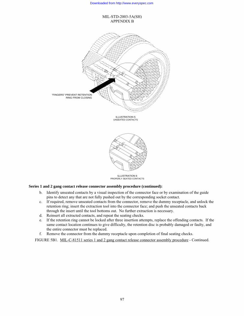
MIL-STD-2003-5A(SH) APPENDIX B
97
Series 1 and 2 gang contact release connector assembly procedure (continued): b. Identify unseated contacts by a visual inspection of the connector face or by examination of the guide
pins to detect any that are not fully pushed out by the corresponding socket contact. c. If required, remove unseated contacts from the connector, remove the dummy receptacle, and unlock the
retention ring; insert the extraction tool into the connector face; and push the unseated contacts back through the insert until the tool bottoms out. No further extraction is necessary.
d. Reinsert all extracted contacts, and repeat the seating checks. e. If the retention ring cannot be locked after three insertion attempts, replace the offending contacts. If the
same contact location continues to give difficulty, the retention disc is probably damaged or faulty, and the entire connector must be replaced.
f. Remove the connector from the dummy receptacle upon completion of final seating checks. FIGURE 5B1. MIL-C-81511 series 1 and 2 gang contact release connector assembly procedure - Continued.
"FINGERS" PREVENT RETENTIONRING FROM CLOSING
ILLUSTRATION 6PROPERLY SEATED CONTACTS
ILLUSTRATION 5UNSEATED CONTACTS
Downloaded from http://www.everyspec.com
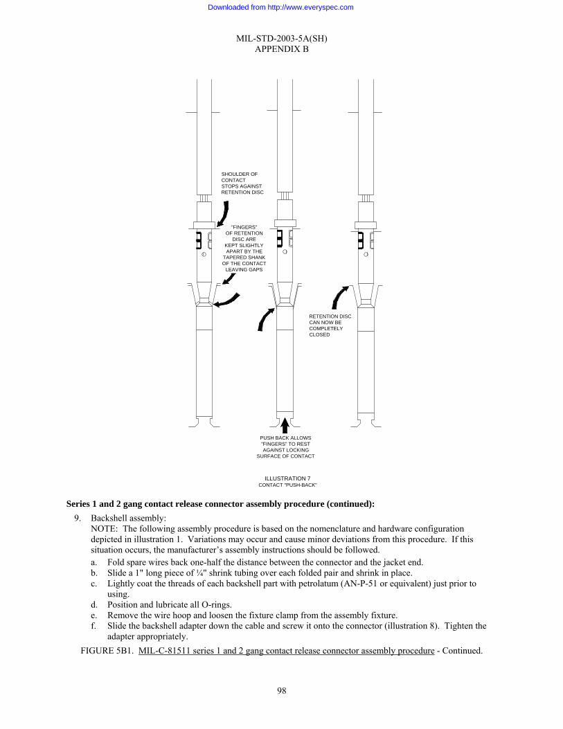
MIL-STD-2003-5A(SH) APPENDIX B
98
Series 1 and 2 gang contact release connector assembly procedure (continued): 9. Backshell assembly:
NOTE: The following assembly procedure is based on the nomenclature and hardware configuration depicted in illustration 1. Variations may occur and cause minor deviations from this procedure. If this situation occurs, the manufacturer’s assembly instructions should be followed. a. Fold spare wires back one-half the distance between the connector and the jacket end. b. Slide a 1" long piece of ¼" shrink tubing over each folded pair and shrink in place. c. Lightly coat the threads of each backshell part with petrolatum (AN-P-51 or equivalent) just prior to
using. d. Position and lubricate all O-rings. e. Remove the wire hoop and loosen the fixture clamp from the assembly fixture. f. Slide the backshell adapter down the cable and screw it onto the connector (illustration 8). Tighten the
adapter appropriately. FIGURE 5B1. MIL-C-81511 series 1 and 2 gang contact release connector assembly procedure - Continued.
ILLUSTRATION 7CONTACT "PUSH-BACK"
SHOULDER OFCONTACTSTOPS AGAINSTRETENTION DISC
RETENTION DISCCAN NOW BECOMPLETELYCLOSED
PUSH BACK ALLOWS"FINGERS" TO RESTAGAINST LOCKING
SURFACE OF CONTACT
"FINGERS"OF RETENTION
DISC AREKEPT SLIGHTLYAPART BY THE
TAPERED SHANKOF THE CONTACT
LEAVING GAPS
Downloaded from http://www.everyspec.com

MIL-STD-2003-5A(SH) APPENDIX B
99
Series 1 and 2 gang contact release connector assembly procedure (continued): g. If the gross shield is to be floated or terminated to a connector contact, proceed to step 10.h. If the shield
is to be terminated to the backshell RFI hardware, proceed as follows: (1) Slide the RFI bell (PC 3, illustration 1) against the backshell adapter. (2) Flare the gross shield uniformly over the tapered end of the RFI bell. Shield shall not extend beyond
the tapered end. (3) Gently force the cable toward the connector plug until the shield covers the tapered surface on the
RFI bell. (4) Slide the RFI ring (PC 4, illustration 1) onto the RFI bell while applying forward pressure on the
cable. (5) Compress the shield between the RFI bell and RFI ring with a forward motion on the RFI ring (see
illustration 9). FIGURE 5B1. MIL-C-81511 series 1 and 2 gang contact release connector assembly procedure - Continued.
SLIDE ADAPTER DOWN
ILLUSTRATION 8BACKSHELL ADAPTER POSITIONING
Downloaded from http://www.everyspec.com
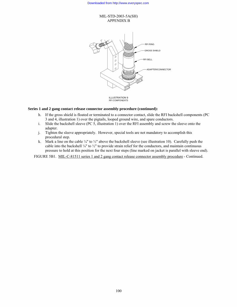
MIL-STD-2003-5A(SH) APPENDIX B
100
Series 1 and 2 gang contact release connector assembly procedure (continued): h. If the gross shield is floated or terminated to a connector contact, slide the RFI backshell components (PC
3 and 4, illustration 1) over the pigtails, looped ground wire, and spare conductors. i. Slide the backshell sleeve (PC 5, illustration 1) over the RFI assembly and screw the sleeve onto the
adapter. j. Tighten the sleeve appropriately. However, special tools are not mandatory to accomplish this
procedural step. k. Mark a line on the cable ¼" to ½" above the backshell sleeve (see illustration 10). Carefully push the
cable into the backshell ¼" to ½" to provide strain relief for the conductors, and maintain continuous pressure to hold at this position for the next four steps (line marked on jacket is parallel with sleeve end).
FIGURE 5B1. MIL-C-81511 series 1 and 2 gang contact release connector assembly procedure - Continued.
ILLUSTRATION 9RFI COMPONENTS
ADAPTER/CONNECTOR
RFI BELL
GROSS SHIELD
RFI RING
Downloaded from http://www.everyspec.com
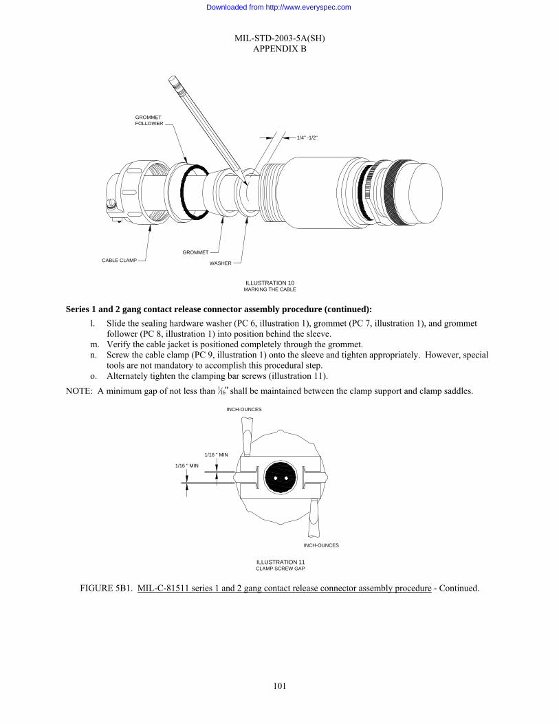
MIL-STD-2003-5A(SH) APPENDIX B
101
Series 1 and 2 gang contact release connector assembly procedure (continued): l. Slide the sealing hardware washer (PC 6, illustration 1), grommet (PC 7, illustration 1), and grommet
follower (PC 8, illustration 1) into position behind the sleeve. m. Verify the cable jacket is positioned completely through the grommet. n. Screw the cable clamp (PC 9, illustration 1) onto the sleeve and tighten appropriately. However, special
tools are not mandatory to accomplish this procedural step. o. Alternately tighten the clamping bar screws (illustration 11).
NOTE: A minimum gap of not less than 1⁄16" shall be maintained between the clamp support and clamp saddles.
FIGURE 5B1. MIL-C-81511 series 1 and 2 gang contact release connector assembly procedure - Continued.
ILLUSTRATION 11CLAMP SCREW GAP
1/16 " MIN
1/16 " MIN
INCH-OUNCES
INCH-OUNCES
1/4" -1/2"
GROMMETFOLLOWER
CABLE CLAMPGROMMET
WASHER
ILLUSTRATION 10MARKING THE CABLE
Downloaded from http://www.everyspec.com

MIL-STD-2003-5A(SH) APPENDIX B
102
Series 1 and 2 gang contact release connector assembly procedure (continued): p. Remove the connector from the assembly and remove the dummy receptacle.
10. Final test and documentation: a. Using established shipyard procedures, perform electrical/electronic checks on the assembled connector. b. Install a protective dust cap on the connector. c. Complete the assembly inspection and documentation as required by local procedures.
11. If necessary, lockwire the connector in accordance with figure 5A9.
FIGURE 5B1. MIL-C-81511 series 1 and 2 gang contact release connector assembly procedure - Continued.
Downloaded from http://www.everyspec.com
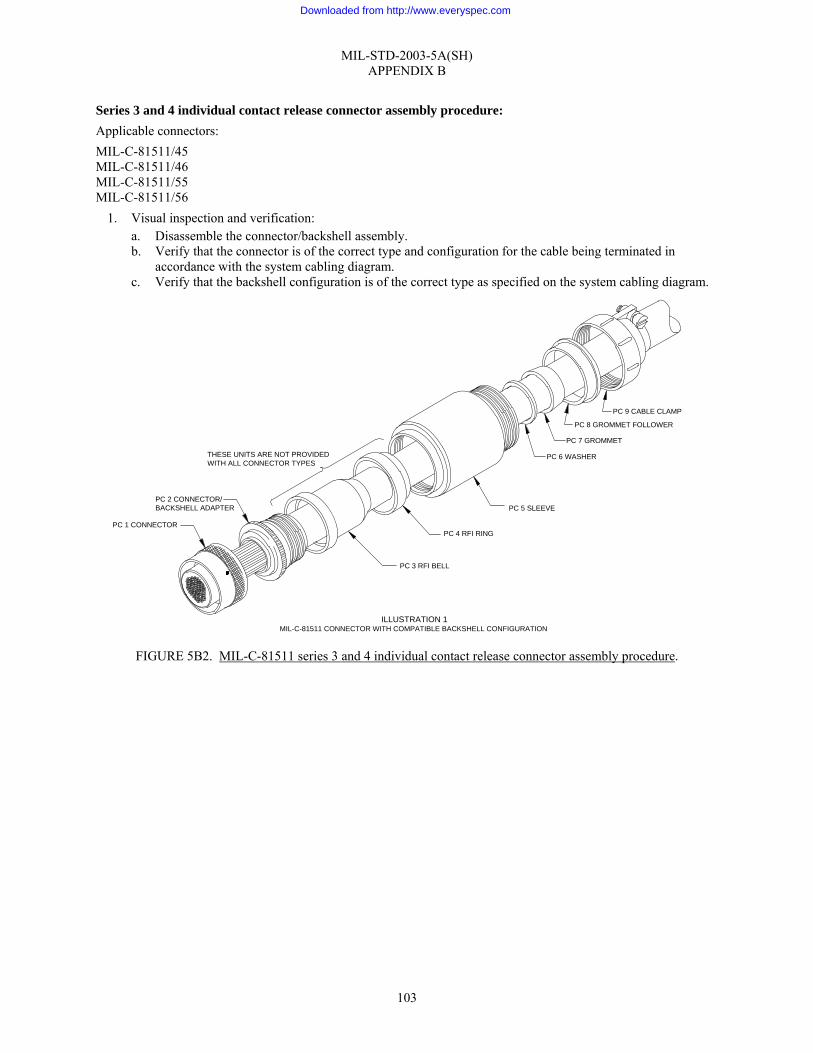
MIL-STD-2003-5A(SH) APPENDIX B
103
Series 3 and 4 individual contact release connector assembly procedure: Applicable connectors: MIL-C-81511/45 MIL-C-81511/46 MIL-C-81511/55 MIL-C-81511/56
1. Visual inspection and verification: a. Disassemble the connector/backshell assembly. b. Verify that the connector is of the correct type and configuration for the cable being terminated in
accordance with the system cabling diagram. c. Verify that the backshell configuration is of the correct type as specified on the system cabling diagram.
FIGURE 5B2. MIL-C-81511 series 3 and 4 individual contact release connector assembly procedure.
PC 1 CONNECTOR
PC 2 CONNECTOR/BACKSHELL ADAPTER
PC 3 RFI BELL
PC 4 RFI RING
PC 5 SLEEVE
PC 9 CABLE CLAMP
PC 8 GROMMET FOLLOWER
PC 7 GROMMET
PC 6 WASHERTHESE UNITS ARE NOT PROVIDEDWITH ALL CONNECTOR TYPES
ILLUSTRATION 1MIL-C-81511 CONNECTOR WITH COMPATIBLE BACKSHELL CONFIGURATION
Downloaded from http://www.everyspec.com
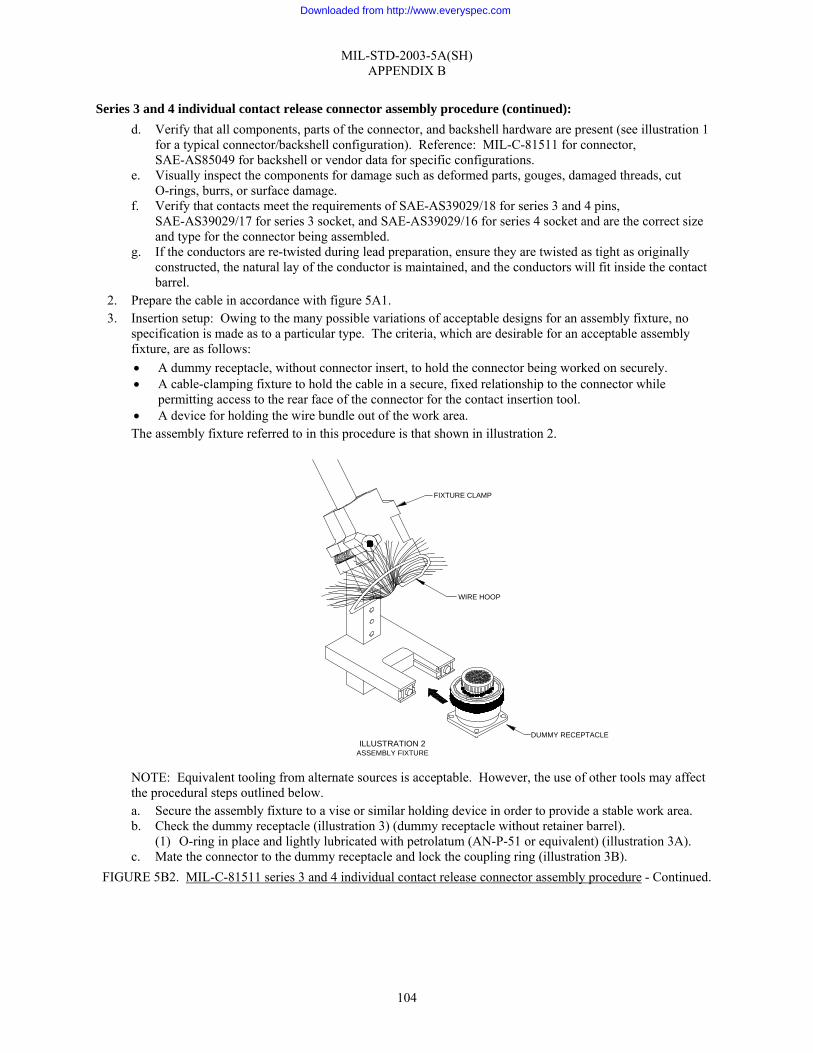
MIL-STD-2003-5A(SH) APPENDIX B
104
Series 3 and 4 individual contact release connector assembly procedure (continued): d. Verify that all components, parts of the connector, and backshell hardware are present (see illustration 1
for a typical connector/backshell configuration). Reference: MIL-C-81511 for connector, SAE-AS85049 for backshell or vendor data for specific configurations.
e. Visually inspect the components for damage such as deformed parts, gouges, damaged threads, cut O-rings, burrs, or surface damage.
f. Verify that contacts meet the requirements of SAE-AS39029/18 for series 3 and 4 pins, SAE-AS39029/17 for series 3 socket, and SAE-AS39029/16 for series 4 socket and are the correct size and type for the connector being assembled.
g. If the conductors are re-twisted during lead preparation, ensure they are twisted as tight as originally constructed, the natural lay of the conductor is maintained, and the conductors will fit inside the contact barrel.
2. Prepare the cable in accordance with figure 5A1. 3. Insertion setup: Owing to the many possible variations of acceptable designs for an assembly fixture, no
specification is made as to a particular type. The criteria, which are desirable for an acceptable assembly fixture, are as follows: • A dummy receptacle, without connector insert, to hold the connector being worked on securely. • A cable-clamping fixture to hold the cable in a secure, fixed relationship to the connector while
permitting access to the rear face of the connector for the contact insertion tool. • A device for holding the wire bundle out of the work area. The assembly fixture referred to in this procedure is that shown in illustration 2.
NOTE: Equivalent tooling from alternate sources is acceptable. However, the use of other tools may affect the procedural steps outlined below. a. Secure the assembly fixture to a vise or similar holding device in order to provide a stable work area. b. Check the dummy receptacle (illustration 3) (dummy receptacle without retainer barrel).
(1) O-ring in place and lightly lubricated with petrolatum (AN-P-51 or equivalent) (illustration 3A). c. Mate the connector to the dummy receptacle and lock the coupling ring (illustration 3B).
FIGURE 5B2. MIL-C-81511 series 3 and 4 individual contact release connector assembly procedure - Continued.
DUMMY RECEPTACLE
WIRE HOOP
FIXTURE CLAMP
ILLUSTRATION 2ASSEMBLY FIXTURE
Downloaded from http://www.everyspec.com
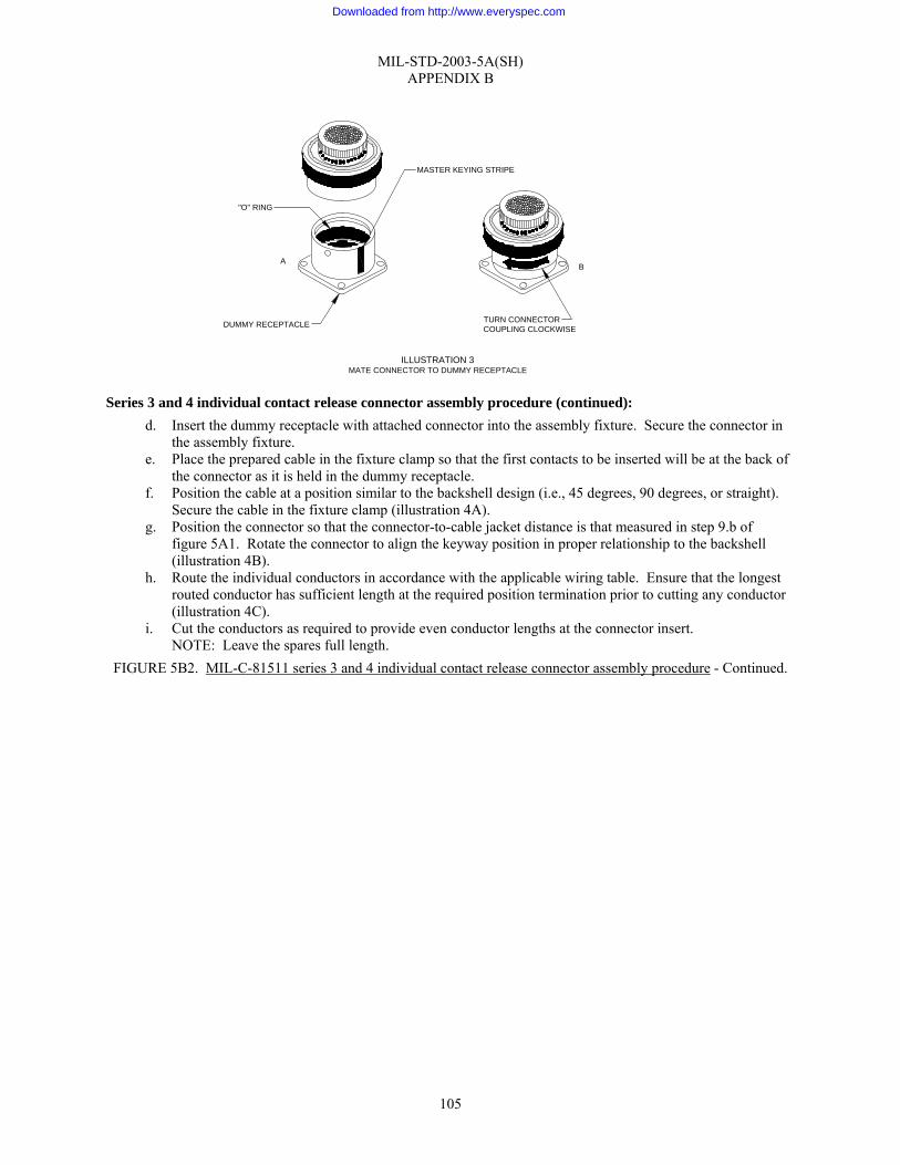
MIL-STD-2003-5A(SH) APPENDIX B
105
Series 3 and 4 individual contact release connector assembly procedure (continued): d. Insert the dummy receptacle with attached connector into the assembly fixture. Secure the connector in
the assembly fixture. e. Place the prepared cable in the fixture clamp so that the first contacts to be inserted will be at the back of
the connector as it is held in the dummy receptacle. f. Position the cable at a position similar to the backshell design (i.e., 45 degrees, 90 degrees, or straight).
Secure the cable in the fixture clamp (illustration 4A). g. Position the connector so that the connector-to-cable jacket distance is that measured in step 9.b of
figure 5A1. Rotate the connector to align the keyway position in proper relationship to the backshell (illustration 4B).
h. Route the individual conductors in accordance with the applicable wiring table. Ensure that the longest routed conductor has sufficient length at the required position termination prior to cutting any conductor (illustration 4C).
i. Cut the conductors as required to provide even conductor lengths at the connector insert. NOTE: Leave the spares full length.
FIGURE 5B2. MIL-C-81511 series 3 and 4 individual contact release connector assembly procedure - Continued.
MASTER KEYING STRIPE
A
DUMMY RECEPTACLE TURN CONNECTORCOUPLING CLOCKWISE
B
ILLUSTRATION 3MATE CONNECTOR TO DUMMY RECEPTACLE
"O" RING
Downloaded from http://www.everyspec.com

MIL-STD-2003-5A(SH) APPENDIX B
106
Series 3 and 4 individual contact release connector assembly procedure (continued): 4. Strip the individual conductors in accordance with figure 5A3 (for contact wire barrel depths, see table
5B2-I).
TABLE 5B2-I. Wire barrel depths.
Wire barrel depth (inch)
Series 3 Series 4 Contact size
Pin Socket Pin Socket
12-12 0.216–0.232 0.216–0.232 0.216–0.232 0.216–0.232 16-16 0.185–0.195 0.185–0.195 0.185–0.195 0.185–0.195 20-20 0.185–0.195 0.185–0.195 0.185–0.195 0.185–0.195 23-22 0.145–0.155 0.145–0.155 0.145–0.155 0.145–0.155 23-28 0.145–0.155 0.145–0.155 0.145–0.155 0.145–0.155
NOTE: For Class L socket contacts, the barrel depth is 0.160" to 0.170".
5. Prior to crimping, a contact sizing test should be accomplished, see step 1.f. 6. Terminate individual conductors with crimp contacts in accordance with figure 5A4, (see table 5B2-II for
proper crimping tool). If contact rework shortens a conductor’s initial length by greater than ¼", the jacket must be cut back again and all conductors re-trimmed to preclude stress. a. Secure the wire bundle in the wire hoop so that the work area at the connector face is clear.
FIGURE 5B2. MIL-C-81511 series 3 and 4 individual contact release connector assembly procedure - Continued.
SECURE CABLEAND ALIGNFOR INSERTION
4A
POSITION DISTANCEAND ALIGN KEYWAY
4B
ROUTELONGEST CONDUCTORBEFORE CUTTING
4C
ILLUSTRATION 4DETERMINING CONDUCTOR LENGTH
Downloaded from http://www.everyspec.com
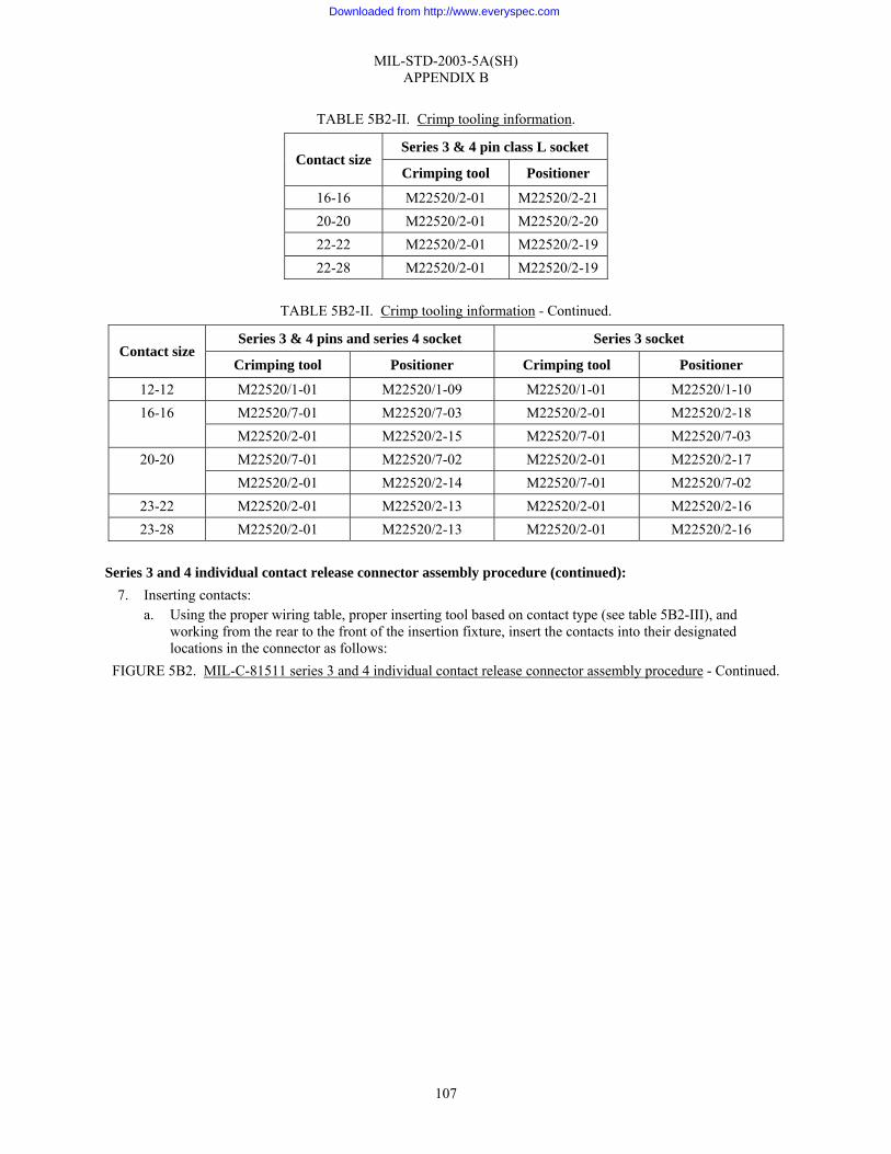
MIL-STD-2003-5A(SH) APPENDIX B
107
TABLE 5B2-II. Crimp tooling information.
Series 3 & 4 pin class L socket Contact size
Crimping tool Positioner
16-16 M22520/2-01 M22520/2-21 20-20 M22520/2-01 M22520/2-20 22-22 M22520/2-01 M22520/2-19 22-28 M22520/2-01 M22520/2-19
TABLE 5B2-II. Crimp tooling information - Continued.
Series 3 & 4 pins and series 4 socket Series 3 socket Contact size
Crimping tool Positioner Crimping tool Positioner
12-12 M22520/1-01 M22520/1-09 M22520/1-01 M22520/1-10 M22520/7-01 M22520/7-03 M22520/2-01 M22520/2-18 16-16 M22520/2-01 M22520/2-15 M22520/7-01 M22520/7-03 M22520/7-01 M22520/7-02 M22520/2-01 M22520/2-17 20-20 M22520/2-01 M22520/2-14 M22520/7-01 M22520/7-02
23-22 M22520/2-01 M22520/2-13 M22520/2-01 M22520/2-16 23-28 M22520/2-01 M22520/2-13 M22520/2-01 M22520/2-16
Series 3 and 4 individual contact release connector assembly procedure (continued):
7. Inserting contacts: a. Using the proper wiring table, proper inserting tool based on contact type (see table 5B2-III), and
working from the rear to the front of the insertion fixture, insert the contacts into their designated locations in the connector as follows:
FIGURE 5B2. MIL-C-81511 series 3 and 4 individual contact release connector assembly procedure - Continued.
Downloaded from http://www.everyspec.com
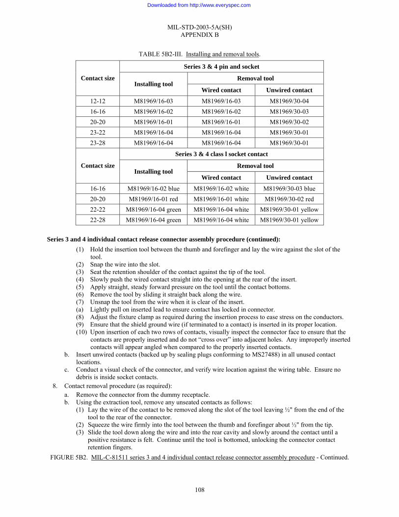
MIL-STD-2003-5A(SH) APPENDIX B
108
TABLE 5B2-III. Installing and removal tools.
Series 3 & 4 pin and socket
Removal tool Contact size Installing tool
Wired contact Unwired contact
12-12 M81969/16-03 M81969/16-03 M81969/30-04 16-16 M81969/16-02 M81969/16-02 M81969/30-03 20-20 M81969/16-01 M81969/16-01 M81969/30-02 23-22 M81969/16-04 M81969/16-04 M81969/30-01 23-28 M81969/16-04 M81969/16-04 M81969/30-01
Series 3 & 4 class l socket contact
Removal tool Contact size Installing tool
Wired contact Unwired contact
16-16 M81969/16-02 blue M81969/16-02 white M81969/30-03 blue 20-20 M81969/16-01 red M81969/16-01 white M81969/30-02 red 22-22 M81969/16-04 green M81969/16-04 white M81969/30-01 yellow 22-28 M81969/16-04 green M81969/16-04 white M81969/30-01 yellow
Series 3 and 4 individual contact release connector assembly procedure (continued):
(1) Hold the insertion tool between the thumb and forefinger and lay the wire against the slot of the tool.
(2) Snap the wire into the slot. (3) Seat the retention shoulder of the contact against the tip of the tool. (4) Slowly push the wired contact straight into the opening at the rear of the insert. (5) Apply straight, steady forward pressure on the tool until the contact bottoms. (6) Remove the tool by sliding it straight back along the wire. (7) Unsnap the tool from the wire when it is clear of the insert. (a) Lightly pull on inserted lead to ensure contact has locked in connector. (8) Adjust the fixture clamp as required during the insertion process to ease stress on the conductors. (9) Ensure that the shield ground wire (if terminated to a contact) is inserted in its proper location. (10) Upon insertion of each two rows of contacts, visually inspect the connector face to ensure that the
contacts are properly inserted and do not “cross over” into adjacent holes. Any improperly inserted contacts will appear angled when compared to the properly inserted contacts.
b. Insert unwired contacts (backed up by sealing plugs conforming to MS27488) in all unused contact locations.
c. Conduct a visual check of the connector, and verify wire location against the wiring table. Ensure no debris is inside socket contacts.
8. Contact removal procedure (as required): a. Remove the connector from the dummy receptacle. b. Using the extraction tool, remove any unseated contacts as follows:
(1) Lay the wire of the contact to be removed along the slot of the tool leaving ½" from the end of the tool to the rear of the connector.
(2) Squeeze the wire firmly into the tool between the thumb and forefinger about ½" from the tip. (3) Slide the tool down along the wire and into the rear cavity and slowly around the contact until a
positive resistance is felt. Continue until the tool is bottomed, unlocking the connector contact retention fingers.
FIGURE 5B2. MIL-C-81511 series 3 and 4 individual contact release connector assembly procedure - Continued.
Downloaded from http://www.everyspec.com
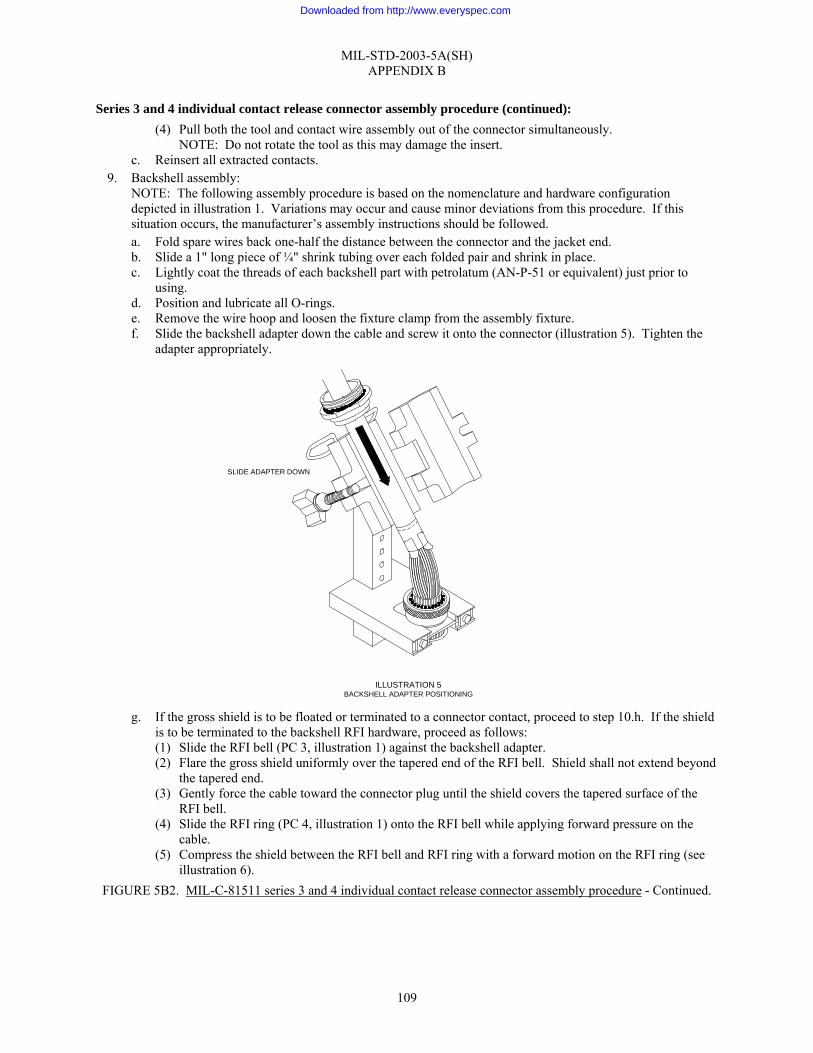
MIL-STD-2003-5A(SH) APPENDIX B
109
Series 3 and 4 individual contact release connector assembly procedure (continued): (4) Pull both the tool and contact wire assembly out of the connector simultaneously.
NOTE: Do not rotate the tool as this may damage the insert. c. Reinsert all extracted contacts.
9. Backshell assembly: NOTE: The following assembly procedure is based on the nomenclature and hardware configuration depicted in illustration 1. Variations may occur and cause minor deviations from this procedure. If this situation occurs, the manufacturer’s assembly instructions should be followed. a. Fold spare wires back one-half the distance between the connector and the jacket end. b. Slide a 1" long piece of ¼" shrink tubing over each folded pair and shrink in place. c. Lightly coat the threads of each backshell part with petrolatum (AN-P-51 or equivalent) just prior to
using. d. Position and lubricate all O-rings. e. Remove the wire hoop and loosen the fixture clamp from the assembly fixture. f. Slide the backshell adapter down the cable and screw it onto the connector (illustration 5). Tighten the
adapter appropriately.
g. If the gross shield is to be floated or terminated to a connector contact, proceed to step 10.h. If the shield
is to be terminated to the backshell RFI hardware, proceed as follows: (1) Slide the RFI bell (PC 3, illustration 1) against the backshell adapter. (2) Flare the gross shield uniformly over the tapered end of the RFI bell. Shield shall not extend beyond
the tapered end. (3) Gently force the cable toward the connector plug until the shield covers the tapered surface of the
RFI bell. (4) Slide the RFI ring (PC 4, illustration 1) onto the RFI bell while applying forward pressure on the
cable. (5) Compress the shield between the RFI bell and RFI ring with a forward motion on the RFI ring (see
illustration 6). FIGURE 5B2. MIL-C-81511 series 3 and 4 individual contact release connector assembly procedure - Continued.
ILLUSTRATION 5BACKSHELL ADAPTER POSITIONING
SLIDE ADAPTER DOWN
Downloaded from http://www.everyspec.com
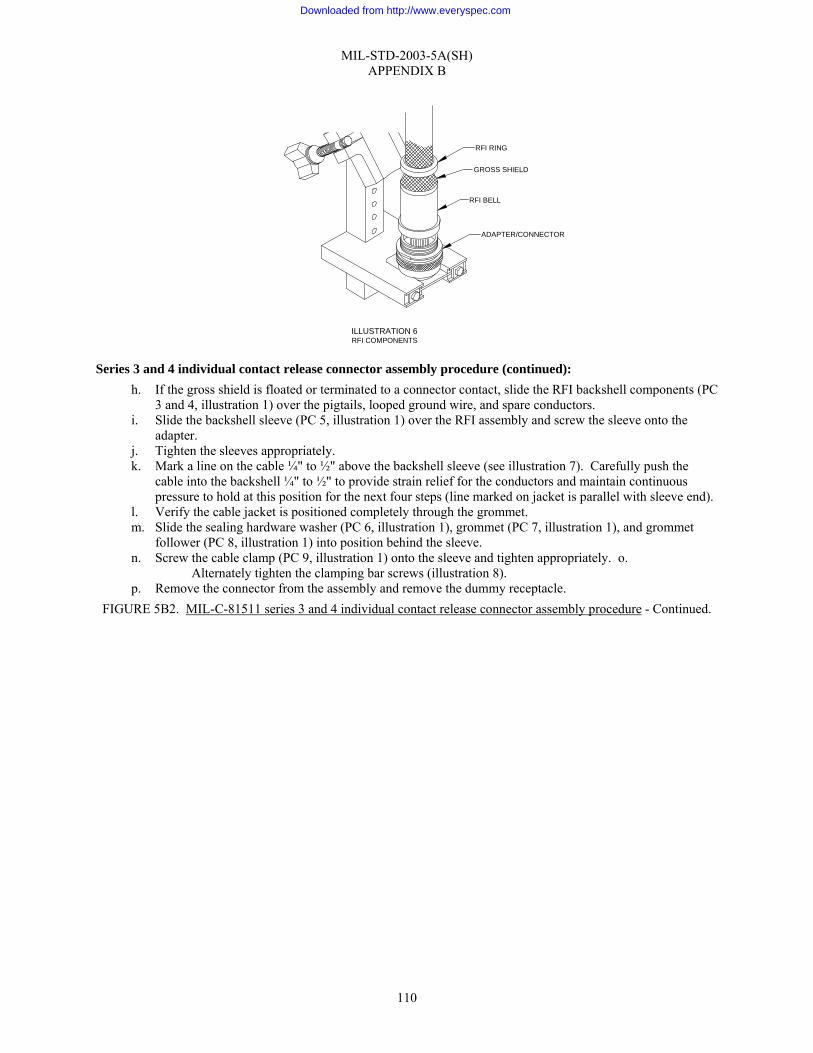
MIL-STD-2003-5A(SH) APPENDIX B
110
Series 3 and 4 individual contact release connector assembly procedure (continued): h. If the gross shield is floated or terminated to a connector contact, slide the RFI backshell components (PC
3 and 4, illustration 1) over the pigtails, looped ground wire, and spare conductors. i. Slide the backshell sleeve (PC 5, illustration 1) over the RFI assembly and screw the sleeve onto the
adapter. j. Tighten the sleeves appropriately. k. Mark a line on the cable ¼" to ½" above the backshell sleeve (see illustration 7). Carefully push the
cable into the backshell ¼" to ½" to provide strain relief for the conductors and maintain continuous pressure to hold at this position for the next four steps (line marked on jacket is parallel with sleeve end).
l. Verify the cable jacket is positioned completely through the grommet. m. Slide the sealing hardware washer (PC 6, illustration 1), grommet (PC 7, illustration 1), and grommet
follower (PC 8, illustration 1) into position behind the sleeve. n. Screw the cable clamp (PC 9, illustration 1) onto the sleeve and tighten appropriately. o.
Alternately tighten the clamping bar screws (illustration 8). p. Remove the connector from the assembly and remove the dummy receptacle.
FIGURE 5B2. MIL-C-81511 series 3 and 4 individual contact release connector assembly procedure - Continued.
ILLUSTRATION 6RFI COMPONENTS
ADAPTER/CONNECTOR
RFI BELL
GROSS SHIELD
RFI RING
Downloaded from http://www.everyspec.com

MIL-STD-2003-5A(SH) APPENDIX B
111
NOTE: Tighten the clamping bar screws to maintain a minimum gap of not less than 1⁄16" between the clamp support and clamp saddles.
Series 3 and 4 individual contact release connector assembly procedure (continued): 10. Final test and documentation:
a. Using established shipyard procedures, perform electrical/electronic checks on the assembled connector. b. Install a protective dust cap on the connector. c. Complete the assembly inspection and documentation as required by local procedures.
11. If necessary, lockwire the connector in accordance with figure 5A9.
FIGURE 5B2. MIL-C-81511 series 3 and 4 individual contact release connector assembly procedure - Continued.
1/16 " MIN
1/16 " MIN
INCH-OUNCES
INCH-OUNCES
ILLUSTRATION 8CLAMP SCREW GAP
GROMMETFOLLOWER
CABLE CLAMPGROMMET
WASHER
ILLUSTRATION 7MARKING THE CABLE
1/4" -1/2"
Downloaded from http://www.everyspec.com
MIL-STD-2003-5A(SH) APPENDIX C
112
GROUP 5C - MIL-DTL-5015 CONNECTORS
C.1 SCOPE
C.1.1 Scope. This appendix describes procedures for the preparation of MIL-DTL-5015 connector assembly.
C.2 APPLICABLE DOCUMENTS
C.2.1 General. The documents listed in this section are specified in this appendix. This section does not include documents cited in other sections of this standard or recommended for additional information or as examples. While every effort has been made to ensure the completeness of this list, document users are cautioned that they must meet all specified requirements of documents cited in this appendix, whether or not they are listed.
C.2.2 Government documents.
C.2.2.1 Specifications, standards, and handbooks. The following specifications, standards, and handbooks form a part of this document to the extent specified herein. Unless otherwise specified, the issues of these documents are those cited in the solicitation or contract.
DEPARTMENT OF DEFENSE SPECIFICATIONS
MIL-DTL-5015 - Connectors, Electrical, Circular Threaded, AN Type, General Specification for
DEPARTMENT OF DEFENSE STANDARDS
MS3101 - Connectors, Receptacle, Electric, Cable Connecting, Front Release, Crimp Contact, AN Type
MS3105 - Connector, Receptacle, Electric Dummy Stowage
MS3106 - Connector, Plug, Electric, Straight, Solder Contacts, AN Type
MS3107 - Connector Plug, Electric, Quick Disconnect
MS3108 - Connectors, Plug, Electric, Solder Contact, 90 Degree, AN Type
MS3187 - Plug, End Seal, for MIL-DTL-26482, MIL-DTL-5015, MIL-C-81703 and MIL-DTL-83723 Electrical Connectors
MS3400 - Connectors, Receptacle, Electric, Wall Mounting, Front Release, Crimp Contact, AN Type
MS3401 - Connectors, Receptacle, Electric, Cable Connecting, Front Release, Crimp Contact, AN Type
MS3406 - Connectors, Plug, Electric, Front Release, Crimp Contact, AN Type
MS3408 - Connector, Plug, Electric, 90 Degree Assembly, Crimp Contact, AN Type
MS3450 - Connector, Receptacle, Electric, Wall Mounting, Rear Release, Crimp Contact, AN Type
MS3451 - Connector, Receptacle, Electrical, Cable Connecting, Rear Release, Crimp Contact, AN Type
MS3456 - Connectors, Plug, Electrical, Rear Release, Crimp Contact, AN Type
MS3459 - Connector, Plug, Electrical, Self-Locking, Coupling Nut, Rear Release, Crimp Contact, AN Type
Downloaded from http://www.everyspec.com

MIL-STD-2003-5A(SH) APPENDIX C
113
MS27488 - Plug, End Seal, Electrical Connector
(Copies of these documents are available online at http://assist.daps.dla.mil/quicksearch/ or from the Standardization Document Order Desk, 700 Robbins Avenue, Building 4D, Philadelphia, PA 19111-5094.)
C.2.3 Non-Government publications. The following documents form a part of this document to the extent specified herein. Unless otherwise specified, the issues of these documents are those cited in the solicitation or contract.
SAE INTERNATIONAL
SAE-AS39029/29 - Contacts, Electrical Connector, Pin, Crimp Removable (for AS50151 Series, AS34501 and MIL-DTL-83723 Series 2 Connectors)
SAE-AS39029/30 - Contacts, Electrical Connector, Socket, Crimp Removable (for AS50151 Series, AS34501 and MIL-DTL-83723 Series 2 Connectors)
SAE-AS39029/44 - Contacts, Electrical Connector, Pin, Crimp Removable (for MIL-DTL-5015 Series MS3400 Connectors)
SAE-AS39029/45 - Contacts, Electrical Connector, Socket, Crimp Removable (for MIL-DTL-5015 Series MS3400 Connectors)
SAE-AS85049 - Connector Accessories, Electrical General Specification For
(Copies of these documents are available from SAE World Headquarters, 400 Commonwealth Drive, Warrendale, PA 15096-0001 or online at www.sae.org.)
C.2.4 Order of precedence. Unless otherwise noted herein or in the contract, in the event of a conflict between the text of this document and the references cited herein, the text of this document takes precedence. Nothing in this document, however, supersedes applicable laws and regulations unless a specific exemption has been obtained.
C.3 REQUIRED EQUIPMENT AND MATERIALS
C.3.1 Required equipment and materials. The required equipment and materials are specified in the standard methods of this section.
C.4 NOTES AND PROCEDURES
C.4.1 Dimensions. For figures and tables in this section, all dimensions are in inches unless otherwise noted.
C.4.2 Figures. Table 5CI provides information for the figures in this group.
TABLE 5CI. Figures for MIL-DTL-5015 connector assembly preparation.
Figure number MIL-DTL-5015 connector assembly procedures Page
5C1 MIL-DTL-5015 solder connector assembly procedure 114 5C2 MIL-DTL-5015 (crimp) connector assembly procedure 119
Downloaded from http://www.everyspec.com

MIL-STD-2003-5A(SH) APPENDIX C
114
MIL-DTL-5015 solder connector assembly procedure: Applicable connectors: MS3101 MS3106 MS3107 MS3108 10-109 series
1. Visual inspection and verification: a. Disassemble the connector/backshell assembly. b. Verify that the connector is of the correct type and configuration for the cable being terminated in
accordance with the system cabling diagram. c. Verify that the backshell configuration is of the correct type as specified on the system cabling diagram. d. Verify that all component parts of the connector and backshell hardware are present. (See illustration 1
for typical connector/backshell configurations.) Reference: MIL-DTL-5015 for connector, SAE-AS85049 for backshell, or vendor data for specific configurations.
e. Visually inspect the components for damage such as deformed parts, gouges, damaged threads, cut
O-rings, burrs, or surface damage. f. If the conductors are re-twisted during lead preparation, ensure they are twisted as tight as originally
constructed, the natural lay of the conductor is maintained, and the conductors will fit inside the contact barrel.
2. Prepare the cable in accordance with figure 5A1. a. The grommet (PC 2) is designed to fit around individual conductors and therefore cannot be placed on
the cable until individual conductors have been exposed in the cable. 3. Insertion set-up: Owing to the many possible variations of acceptable designs for an assembly fixture, no
specification is made as to a particular type. The criteria which are desirable for an acceptable assembly fixture are as follows:
FIGURE 5C1. MIL-DTL-5015 solder connector assembly procedure.
SOLDER CONTACTS
PC 1 CONNECTOR
PC 2 GROMMET
PC 3 FERRULE
PC 4 ENDBELL
MS-3106RSTRAIGHT PLUG
CENTERING POST
CLAMPING BARS
MS-3106F STRAIGHT PLUG
ILLUSTRATION 1TYPICAL CONNECTOR/BACKSHELL
CONFIGURATION
Downloaded from http://www.everyspec.com
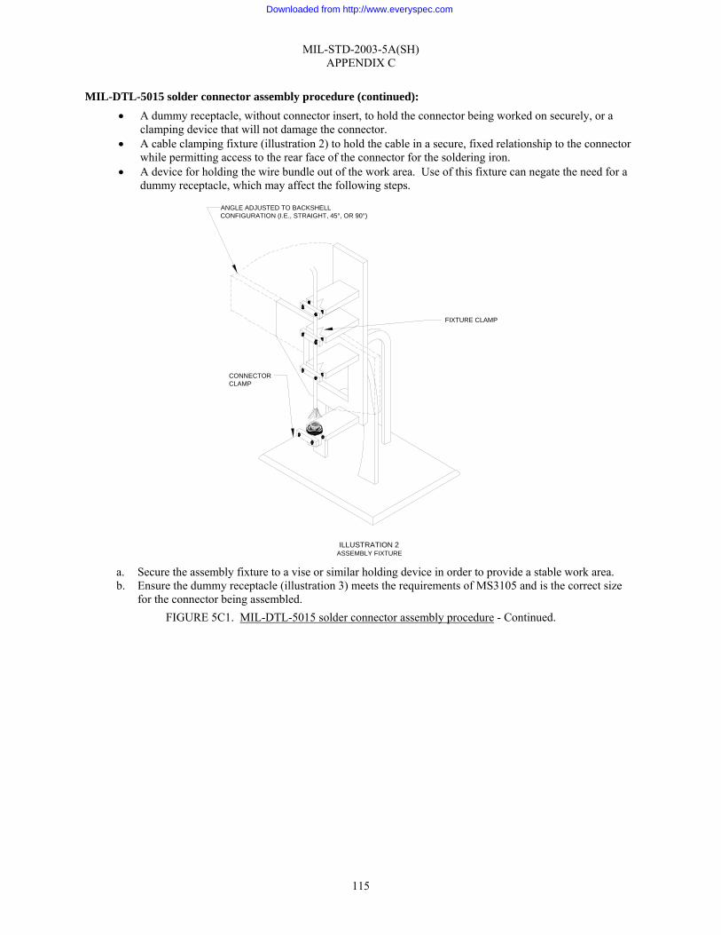
MIL-STD-2003-5A(SH) APPENDIX C
115
MIL-DTL-5015 solder connector assembly procedure (continued): • A dummy receptacle, without connector insert, to hold the connector being worked on securely, or a
clamping device that will not damage the connector. • A cable clamping fixture (illustration 2) to hold the cable in a secure, fixed relationship to the connector
while permitting access to the rear face of the connector for the soldering iron. • A device for holding the wire bundle out of the work area. Use of this fixture can negate the need for a
dummy receptacle, which may affect the following steps.
a. Secure the assembly fixture to a vise or similar holding device in order to provide a stable work area. b. Ensure the dummy receptacle (illustration 3) meets the requirements of MS3105 and is the correct size
for the connector being assembled. FIGURE 5C1. MIL-DTL-5015 solder connector assembly procedure - Continued.
ILLUSTRATION 2ASSEMBLY FIXTURE
FIXTURE CLAMP
ANGLE ADJUSTED TO BACKSHELLCONFIGURATION (I.E., STRAIGHT, 45°, OR 90°)
CONNECTORCLAMP
Downloaded from http://www.everyspec.com
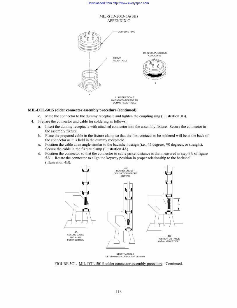
MIL-STD-2003-5A(SH) APPENDIX C
116
MIL-DTL-5015 solder connector assembly procedure (continued):
c. Mate the connector to the dummy receptacle and tighten the coupling ring (illustration 3B). 4. Prepare the connector and cable for soldering as follows:
a. Insert the dummy receptacle with attached connector into the assembly fixture. Secure the connector in the assembly fixture.
b. Place the prepared cable in the fixture clamp so that the first contacts to be soldered will be at the back of the connector as it is held in the dummy receptacle.
c. Position the cable at an angle similar to the backshell design (i.e., 45 degrees, 90 degrees, or straight). Secure the cable in the fixture clamp (illustration 4A).
d. Position the connector so that the connector to cable jacket distance is that measured in step 9.b of figure 5A1. Rotate the connector to align the keyway position in proper relationship to the backshell (illustration 4B).
FIGURE 5C1. MIL-DTL-5015 solder connector assembly procedure - Continued.
4CROUTE LONGEST
CONDUCTOR BEFORECUTTING
4ASECURE CABLE
AND ALIGNFOR INSERTION
4BPOSITION DISTANCEAND ALIGN KEYWAY
D
ILLUSTRATION 4DETERMINING CONDUCTOR LENGTH
ILLUSTRATION 3MATING CONNECTOR TO
DUMMY RECEPTACLE
COUPLING RING
TURN COUPLING RINGCLOCKWISE
A
B
DUMMYRECEPTACLE
Downloaded from http://www.everyspec.com
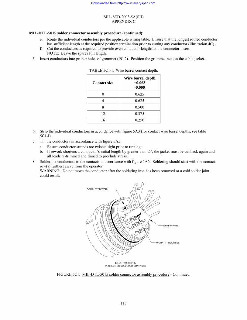
MIL-STD-2003-5A(SH) APPENDIX C
117
MIL-DTL-5015 solder connector assembly procedure (continued): e. Route the individual conductors per the applicable wiring table. Ensure that the longest routed conductor
has sufficient length at the required position termination prior to cutting any conductor (illustration 4C). f. Cut the conductors as required to provide even conductor lengths at the connector insert.
NOTE: Leave the spares full length. 5. Insert conductors into proper holes of grommet (PC 2). Position the grommet next to the cable jacket.
TABLE 5C1-I. Wire barrel contact depth.
Contact size Wire barrel depth
+0.063 -0.000
0 0.625 4 0.625 8 0.500
12 0.375 16 0.250
6. Strip the individual conductors in accordance with figure 5A3 (for contact wire barrel depths, see table
5C1-I). 7. Tin the conductors in accordance with figure 5A5.
a. Ensure conductor strands are twisted tight prior to tinning. b. If rework shortens a conductor’s initial length by greater than ¼", the jacket must be cut back again and
all leads re-trimmed and tinned to preclude stress. 8. Solder the conductors to the contacts in accordance with figure 5A6. Soldering should start with the contact
row(s) furthest away from the operator. WARNING: Do not move the conductor after the soldering iron has been removed or a cold solder joint could result.
FIGURE 5C1. MIL-DTL-5015 solder connector assembly procedure - Continued.
ILLUSTRATION 5PROTECTING SOLDERED CONTACTS
COMPLETED WORK
WORK IN PROGRESS
STIFF PAPER
Downloaded from http://www.everyspec.com
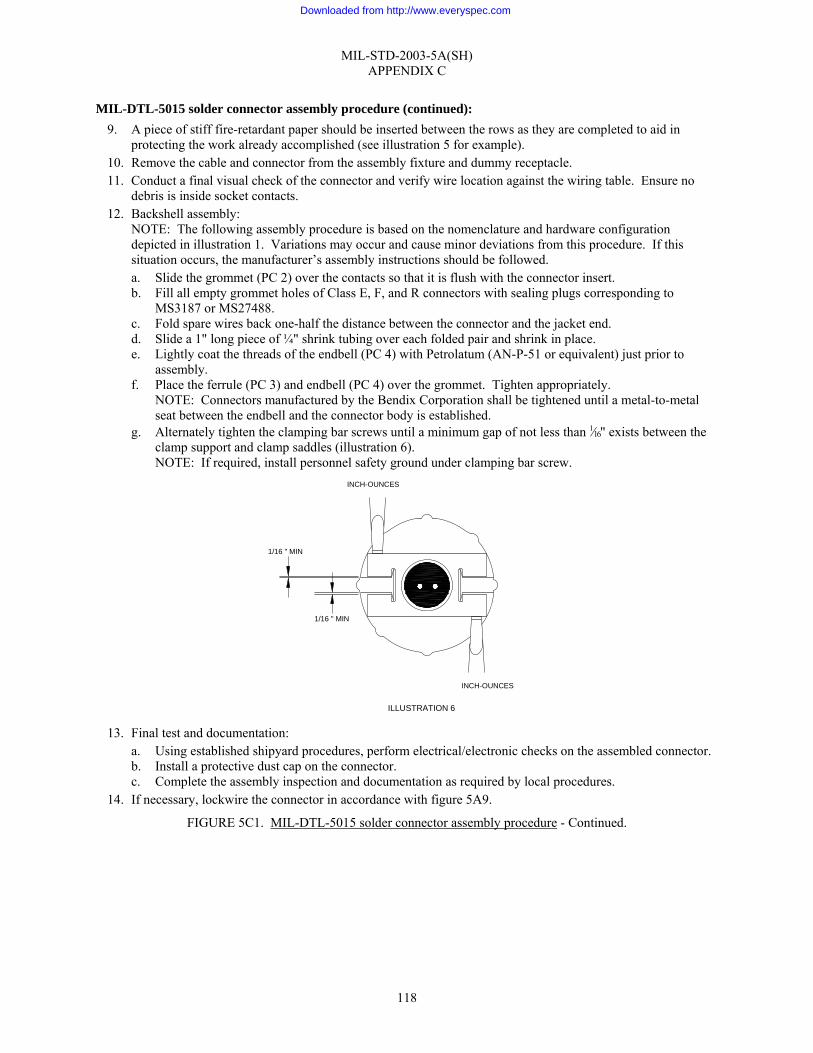
MIL-STD-2003-5A(SH) APPENDIX C
118
MIL-DTL-5015 solder connector assembly procedure (continued): 9. A piece of stiff fire-retardant paper should be inserted between the rows as they are completed to aid in
protecting the work already accomplished (see illustration 5 for example). 10. Remove the cable and connector from the assembly fixture and dummy receptacle. 11. Conduct a final visual check of the connector and verify wire location against the wiring table. Ensure no
debris is inside socket contacts. 12. Backshell assembly:
NOTE: The following assembly procedure is based on the nomenclature and hardware configuration depicted in illustration 1. Variations may occur and cause minor deviations from this procedure. If this situation occurs, the manufacturer’s assembly instructions should be followed. a. Slide the grommet (PC 2) over the contacts so that it is flush with the connector insert. b. Fill all empty grommet holes of Class E, F, and R connectors with sealing plugs corresponding to
MS3187 or MS27488. c. Fold spare wires back one-half the distance between the connector and the jacket end. d. Slide a 1" long piece of ¼" shrink tubing over each folded pair and shrink in place. e. Lightly coat the threads of the endbell (PC 4) with Petrolatum (AN-P-51 or equivalent) just prior to
assembly. f. Place the ferrule (PC 3) and endbell (PC 4) over the grommet. Tighten appropriately.
NOTE: Connectors manufactured by the Bendix Corporation shall be tightened until a metal-to-metal seat between the endbell and the connector body is established.
g. Alternately tighten the clamping bar screws until a minimum gap of not less than 1⁄16" exists between the clamp support and clamp saddles (illustration 6). NOTE: If required, install personnel safety ground under clamping bar screw.
13. Final test and documentation:
a. Using established shipyard procedures, perform electrical/electronic checks on the assembled connector. b. Install a protective dust cap on the connector. c. Complete the assembly inspection and documentation as required by local procedures.
14. If necessary, lockwire the connector in accordance with figure 5A9.
FIGURE 5C1. MIL-DTL-5015 solder connector assembly procedure - Continued.
1/16 " MIN
ILLUSTRATION 6
1/16 " MIN
INCH-OUNCES
INCH-OUNCES
Downloaded from http://www.everyspec.com
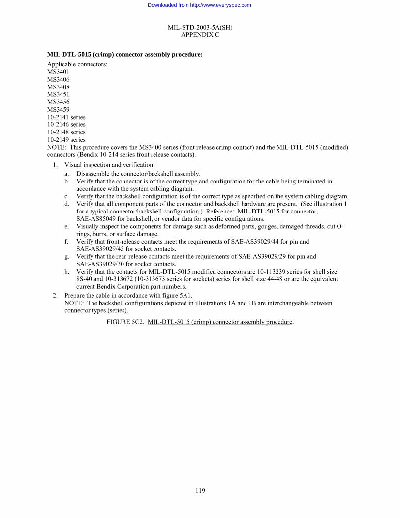
MIL-STD-2003-5A(SH) APPENDIX C
119
MIL-DTL-5015 (crimp) connector assembly procedure: Applicable connectors: MS3401 MS3406 MS3408 MS3451 MS3456 MS3459 10-2141 series 10-2146 series 10-2148 series 10-2149 series NOTE: This procedure covers the MS3400 series (front release crimp contact) and the MIL-DTL-5015 (modified) connectors (Bendix 10-214 series front release contacts).
1. Visual inspection and verification: a. Disassemble the connector/backshell assembly. b. Verify that the connector is of the correct type and configuration for the cable being terminated in
accordance with the system cabling diagram. c. Verify that the backshell configuration is of the correct type as specified on the system cabling diagram. d. Verify that all component parts of the connector and backshell hardware are present. (See illustration 1
for a typical connector/backshell configuration.) Reference: MIL-DTL-5015 for connector, SAE-AS85049 for backshell, or vendor data for specific configurations.
e. Visually inspect the components for damage such as deformed parts, gouges, damaged threads, cut O-rings, burrs, or surface damage.
f. Verify that front-release contacts meet the requirements of SAE-AS39029/44 for pin and SAE-AS39029/45 for socket contacts.
g. Verify that the rear-release contacts meet the requirements of SAE-AS39029/29 for pin and SAE-AS39029/30 for socket contacts.
h. Verify that the contacts for MIL-DTL-5015 modified connectors are 10-113239 series for shell size 8S-40 and 10-313672 (10-313673 series for sockets) series for shell size 44-48 or are the equivalent current Bendix Corporation part numbers.
2. Prepare the cable in accordance with figure 5A1. NOTE: The backshell configurations depicted in illustrations 1A and 1B are interchangeable between connector types (series).
FIGURE 5C2. MIL-DTL-5015 (crimp) connector assembly procedure.
Downloaded from http://www.everyspec.com
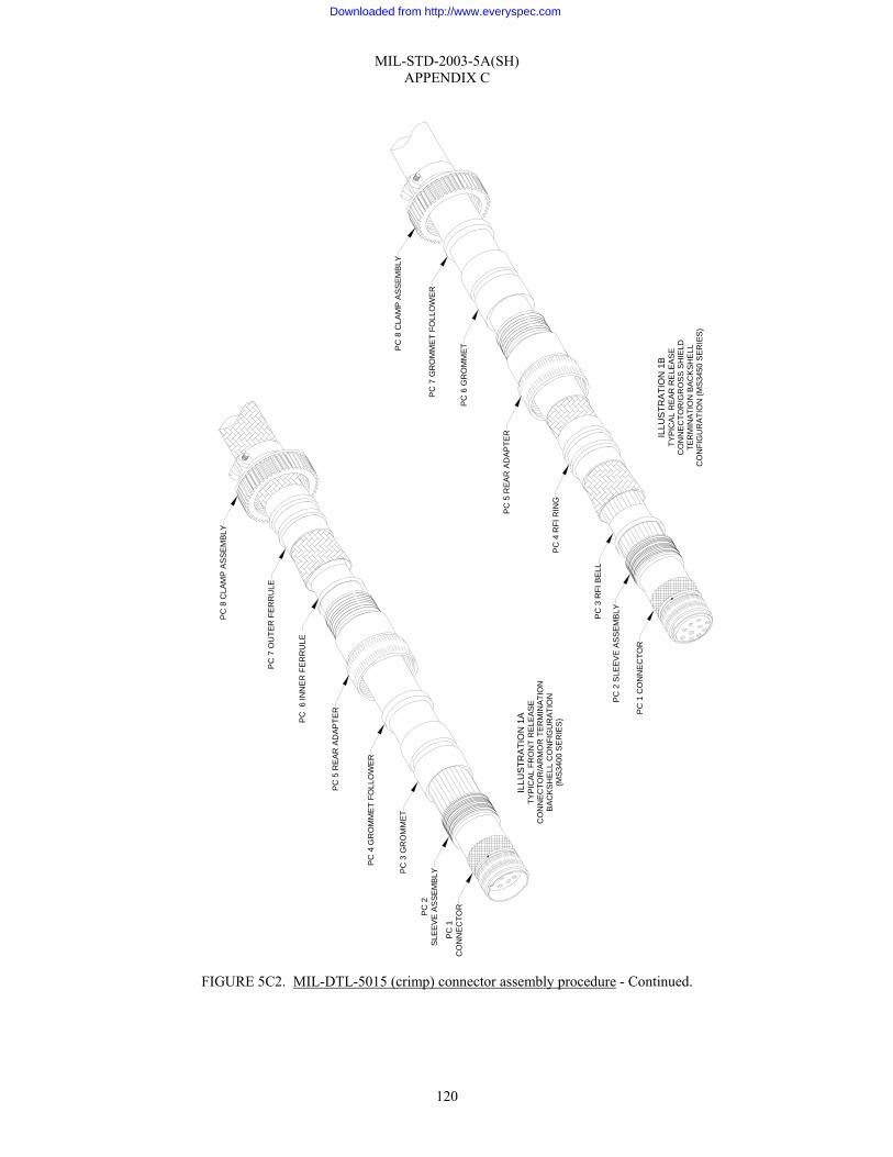
MIL-STD-2003-5A(SH) APPENDIX C
120
FIGURE 5C2. MIL-DTL-5015 (crimp) connector assembly procedure - Continued.
PC
1C
ON
NE
CTO
R
ILLU
STR
ATI
ON
1B
TYP
ICA
L R
EAR
RE
LEA
SEC
ON
NE
CTO
R/G
RO
SS
SH
IELD
TER
MIN
ATI
ON
BA
CK
SH
ELL
CO
NFI
GU
RA
TIO
N (M
S34
50 S
ER
IES
)
PC
1 C
ON
NE
CTO
R
PC
2 S
LEE
VE
AS
SE
MB
LYPC
3 R
FI B
ELL
PC
4 R
FI R
ING
PC
5 R
EA
R A
DA
PTE
R
PC
6 G
RO
MM
ET
PC
7 G
RO
MM
ET
FOLL
OW
ER
PC
8 C
LAM
P A
SS
EM
BLY
PC
2S
LEE
VE
AS
SE
MB
LYPC 3
GR
OM
MET
PC
4 G
RO
MM
ET
FOLL
OW
ER
PC
5 R
EA
R A
DA
PTE
R
PC
6 IN
NE
R F
ER
RU
LE
PC
8 C
LAM
P A
SS
EM
BLY
PC
7 O
UTE
R F
ER
RU
LE
ILLU
STR
ATIO
N 1
ATY
PIC
AL
FRO
NT
RE
LEA
SE
CO
NN
EC
TOR
/AR
MO
R T
ER
MIN
ATIO
NB
AC
KS
HE
LL C
ON
FIG
UR
ATIO
N(M
S34
00 S
ER
IES
)
Downloaded from http://www.everyspec.com
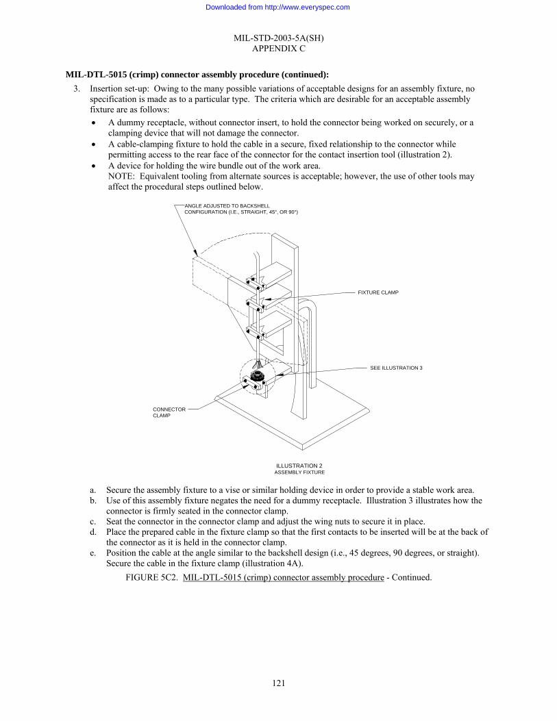
MIL-STD-2003-5A(SH) APPENDIX C
121
MIL-DTL-5015 (crimp) connector assembly procedure (continued): 3. Insertion set-up: Owing to the many possible variations of acceptable designs for an assembly fixture, no
specification is made as to a particular type. The criteria which are desirable for an acceptable assembly fixture are as follows: • A dummy receptacle, without connector insert, to hold the connector being worked on securely, or a
clamping device that will not damage the connector. • A cable-clamping fixture to hold the cable in a secure, fixed relationship to the connector while
permitting access to the rear face of the connector for the contact insertion tool (illustration 2). • A device for holding the wire bundle out of the work area.
NOTE: Equivalent tooling from alternate sources is acceptable; however, the use of other tools may affect the procedural steps outlined below.
a. Secure the assembly fixture to a vise or similar holding device in order to provide a stable work area. b. Use of this assembly fixture negates the need for a dummy receptacle. Illustration 3 illustrates how the
connector is firmly seated in the connector clamp. c. Seat the connector in the connector clamp and adjust the wing nuts to secure it in place. d. Place the prepared cable in the fixture clamp so that the first contacts to be inserted will be at the back of
the connector as it is held in the connector clamp. e. Position the cable at the angle similar to the backshell design (i.e., 45 degrees, 90 degrees, or straight).
Secure the cable in the fixture clamp (illustration 4A). FIGURE 5C2. MIL-DTL-5015 (crimp) connector assembly procedure - Continued.
FIXTURE CLAMP
ANGLE ADJUSTED TO BACKSHELLCONFIGURATION (I.E., STRAIGHT, 45°, OR 90°)
CONNECTORCLAMP
SEE ILLUSTRATION 3
ILLUSTRATION 2ASSEMBLY FIXTURE
Downloaded from http://www.everyspec.com
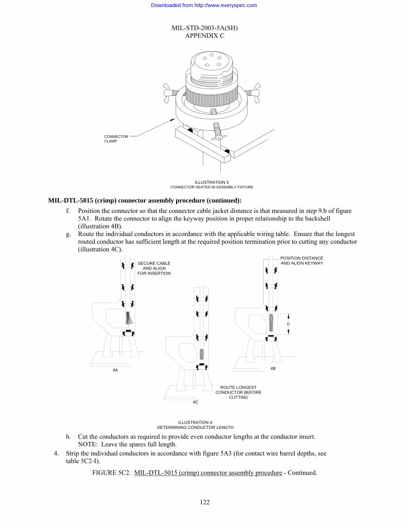
MIL-STD-2003-5A(SH) APPENDIX C
122
MIL-DTL-5015 (crimp) connector assembly procedure (continued):
f. Position the connector so that the connector cable jacket distance is that measured in step 9.b of figure 5A1. Rotate the connector to align the keyway position in proper relationship to the backshell (illustration 4B).
g. Route the individual conductors in accordance with the applicable wiring table. Ensure that the longest routed conductor has sufficient length at the required position termination prior to cutting any conductor (illustration 4C).
h. Cut the conductors as required to provide even conductor lengths at the conductor insert.
NOTE: Leave the spares full length. 4. Strip the individual conductors in accordance with figure 5A3 (for contact wire barrel depths, see
table 5C2-I).
FIGURE 5C2. MIL-DTL-5015 (crimp) connector assembly procedure - Continued.
ILLUSTRATION 4DETERMINING CONDUCTOR LENGTH
ROUTE LONGESTCONDUCTOR BEFORE
CUTTING
SECURE CABLEAND ALIGN
FOR INSERTION
POSITION DISTANCEAND ALIGN KEYWAY
4C
4A 4B
D
ILLUSTRATION 3CONNECTOR SEATED IN ASSEMBLY FIXTURE
CONNECTORCLAMP
Downloaded from http://www.everyspec.com

MIL-STD-2003-5A(SH) APPENDIX C
123
TABLE 5C2-I. Wire barrel contact depth.
Wire barrel depth (inch) Contact barrel size Front release Rear release
0 0.636–0.690 0.610–0.630 4 0.484–0.534 0.485–0.516 8 0.484–0.534 0.485–0.516
12 0.250–0.261 0.250–0.266 16 0.250–0.261 0.250–0.266 20 0.250–0.270 N/A
MIL-DTL-5015 (crimp) connector assembly procedure (continued):
5. Terminate individual conductors with crimp contacts in accordance with figure 5A4 (see table 5C2-II for proper crimping tool). If contact rework shortens a conductor’s initial length by greater than ¼", the jacket must be cut back again and all conductors re-trimmed to preclude stress.
FIGURE 5C2. MIL-DTL-5015 (crimp) connector assembly procedure - Continued.
PC 1 CONNECTOR
PC 2 REAR ADAPTER
PC 3 GROMMET
PC 4 GROMMET FOLLOWER
PC 5 CLAMP ASSEMBLY
ILLUSTRATION 5TYPICAL MIL-DTL-5015 (MODIFIED)
CONNECTOR/BACKSHELL CONFIGURATION
Downloaded from http://www.everyspec.com

MIL-STD-2003-5A(SH) APPENDIX C
124
TABLE 5C2-II. Front release.
Contact size Basic crimping tool Positioner Die set Locator
0-0 M22520/23-01 -- M22520/23-05 M22520/23-13 4-4 M22520/23-01 -- M22520/23-04 M22520/23-11 8-8 M22520/23-01 -- M22520/23-02 M22520/23-09
12-12 M22520/1-01 M22520/1-02 yellow
-- --
12-16 M22520/1-01 M22520/1-02 yellow
-- --
16-16 M22520/1-01 M22520/1-02 blue
-- --
16-20 M22520/1-01 M22520/1-02 blue
-- --
NOTE: See table 5C2-IV for MIL-DTL-5015 modified connector.
TABLE 5C2-III. Rear release.
Contact size Basic crimping tool Positioner Die set Locator
0-0 M22520/23-01 -- M22520/23-05 M22520/23-13 4-4 M22520/23-01 -- M22520/23-04 M22520/23-11 8-8 M22520/23-01 -- M22520/23-02 M22520/23-09
12-12 M22520/1-01 M22520/1-02 yellow
-- --
12-16 -- -- -- -- 16-16 M22520/7-01
M22520/1-01 M22520/17-03 M22520/1-02
blue
-- --
16-22 -- -- -- -- MIL-DTL-5015 (crimp) connector assembly procedure (continued):
6. Inserting contacts: a. Using the proper wiring table, proper inserting tool based on contact type (see table 5C2-III), and
working from the rear to the front of the assembly fixture, insert the contacts into their designated locations in the connector as follows:
FIGURE 5C2. MIL-DTL-5015 (crimp) connector assembly procedure - Continued.
Downloaded from http://www.everyspec.com

MIL-STD-2003-5A(SH) APPENDIX C
125
TABLE 5C2-IV. Tools for modified MIL-DTL-5015 connectors.
Front release Rear release Contact size
Insertion tool Removal tool Insertion tool Removal tool
0-0 M81969/17-08 M81969/19-05 -- M81969/29-04 4-4 M81969/17-07 M81969/19-04 -- M81969/29-03 8-8 M81969/17-06 M81969/19-03 -- M81969/29-02
12-12 M81969/17-02 M81969/19-02 M81969/14-04 M81969/14-04 12-16 M81969//17-01 M81969//19-01 -- -- 16-16 M81969/17-01 M81969/19-01 M81969/14-03 M81969/14-03 16-22 M81969/17-01 M81969/19-01 -- --
NOTE: See table 5C2-IV for MIL-DTL-5015 modified connector. NOTE: For MIL-DTL-5015 modified connectors with socket contacts, install socket contact pilot pins in the connector (table 5C2-IV). Proceed to step 7.a(4) for contact insertion procedure.
(1) Insert a wired contact into the rear of the insert. (2) Seat the contact by positioning the insertion tool around the rear of the contact shoulder with a slight
angle toward the contact to assure a firm grip (illustration 6).
FIGURE 5C2. MIL-DTL-5015 (crimp) connector assembly procedure - Continued.
SEAT CONTACT WITHINSERTION TOOL
POSITION INSERTION TOOLON CONTACT SHOULDER
ILLUSTRATION 6CONTACT INSERTION
Downloaded from http://www.everyspec.com
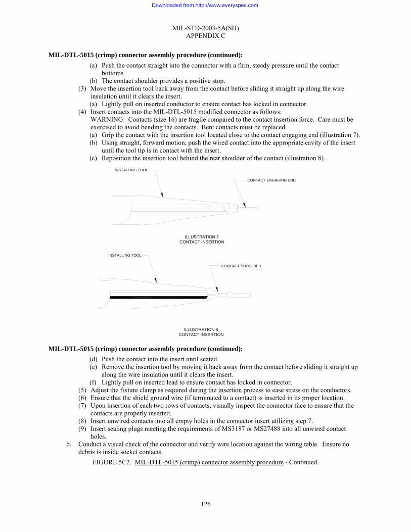
MIL-STD-2003-5A(SH) APPENDIX C
126
MIL-DTL-5015 (crimp) connector assembly procedure (continued): (a) Push the contact straight into the connector with a firm, steady pressure until the contact
bottoms. (b) The contact shoulder provides a positive stop.
(3) Move the insertion tool back away from the contact before sliding it straight up along the wire insulation until it clears the insert. (a) Lightly pull on inserted conductor to ensure contact has locked in connector.
(4) Insert contacts into the MIL-DTL-5015 modified connector as follows: WARNING: Contacts (size 16) are fragile compared to the contact insertion force. Care must be exercised to avoid bending the contacts. Bent contacts must be replaced. (a) Grip the contact with the insertion tool located close to the contact engaging end (illustration 7). (b) Using straight, forward motion, push the wired contact into the appropriate cavity of the insert
until the tool tip is in contact with the insert. (c) Reposition the insertion tool behind the rear shoulder of the contact (illustration 8).
MIL-DTL-5015 (crimp) connector assembly procedure (continued): (d) Push the contact into the insert until seated. (e) Remove the insertion tool by moving it back away from the contact before sliding it straight up
along the wire insulation until it clears the insert. (f) Lightly pull on inserted lead to ensure contact has locked in connector.
(5) Adjust the fixture clamp as required during the insertion process to ease stress on the conductors. (6) Ensure that the shield ground wire (if terminated to a contact) is inserted in its proper location. (7) Upon insertion of each two rows of contacts, visually inspect the connector face to ensure that the
contacts are properly inserted. (8) Insert unwired contacts into all empty holes in the connector insert utilizing step 7. (9) Insert sealing plugs meeting the requirements of MS3187 or MS27488 into all unwired contact
holes. b. Conduct a visual check of the connector and verify wire location against the wiring table. Ensure no
debris is inside socket contacts. FIGURE 5C2. MIL-DTL-5015 (crimp) connector assembly procedure - Continued.
ILLUSTRATION 8CONTACT INSERTION
CONTACT SHOULDER
INSTALLING TOOL
CONTACT ENGAGING END
ILLUSTRATION 7CONTACT INSERTION
INSTALLING TOOL
Downloaded from http://www.everyspec.com
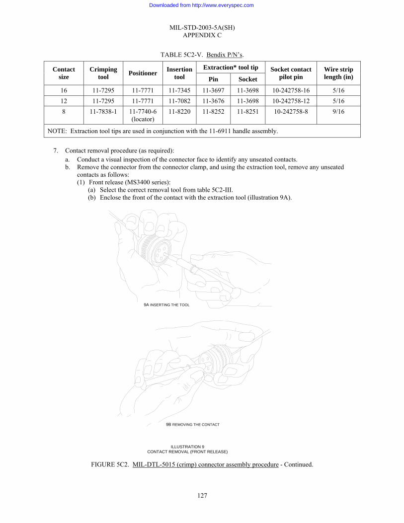
MIL-STD-2003-5A(SH) APPENDIX C
127
TABLE 5C2-V. Bendix P/N’s.
Extraction* tool tip Contact size
Crimping tool Positioner Insertion
tool Pin Socket Socket contact
pilot pin Wire strip length (in)
16 11-7295 11-7771 11-7345 11-3697 11-3698 10-242758-16 5/16 12 11-7295 11-7771 11-7082 11-3676 11-3698 10-242758-12 5/16 8 11-7838-1 11-7740-6
(locator) 11-8220 11-8252 11-8251 10-242758-8 9/16
NOTE: Extraction tool tips are used in conjunction with the 11-6911 handle assembly.
7. Contact removal procedure (as required): a. Conduct a visual inspection of the connector face to identify any unseated contacts. b. Remove the connector from the connector clamp, and using the extraction tool, remove any unseated
contacts as follows: (1) Front release (MS3400 series):
(a) Select the correct removal tool from table 5C2-III. (b) Enclose the front of the contact with the extraction tool (illustration 9A).
FIGURE 5C2. MIL-DTL-5015 (crimp) connector assembly procedure - Continued.
9B REMOVING THE CONTACT
ILLUSTRATION 9CONTACT REMOVAL (FRONT RELEASE)
9A INSERTING THE TOOL
Downloaded from http://www.everyspec.com
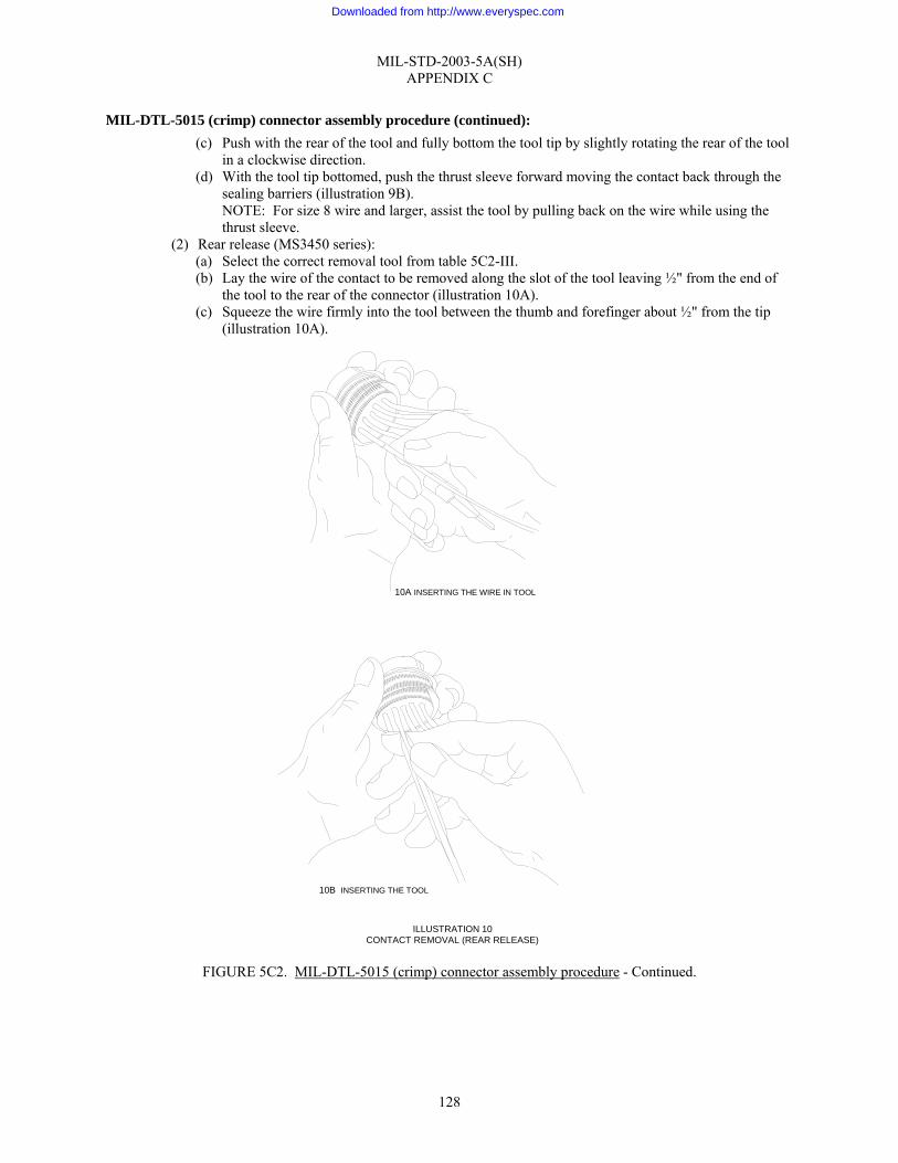
MIL-STD-2003-5A(SH) APPENDIX C
128
MIL-DTL-5015 (crimp) connector assembly procedure (continued): (c) Push with the rear of the tool and fully bottom the tool tip by slightly rotating the rear of the tool
in a clockwise direction. (d) With the tool tip bottomed, push the thrust sleeve forward moving the contact back through the
sealing barriers (illustration 9B). NOTE: For size 8 wire and larger, assist the tool by pulling back on the wire while using the thrust sleeve.
(2) Rear release (MS3450 series): (a) Select the correct removal tool from table 5C2-III. (b) Lay the wire of the contact to be removed along the slot of the tool leaving ½" from the end of
the tool to the rear of the connector (illustration 10A). (c) Squeeze the wire firmly into the tool between the thumb and forefinger about ½" from the tip
(illustration 10A).
FIGURE 5C2. MIL-DTL-5015 (crimp) connector assembly procedure - Continued.
10A INSERTING THE WIRE IN TOOL
10B INSERTING THE TOOL
ILLUSTRATION 10CONTACT REMOVAL (REAR RELEASE)
Downloaded from http://www.everyspec.com

MIL-STD-2003-5A(SH) APPENDIX C
129
MIL-DTL-5015 (crimp) connector assembly procedure (continued): (d) Slide the tool down along the wire and into the rear cavity and slowly around the contact until a
positive resistance is felt (illustration 10B). Continue until the tool is bottomed, unlocking connector contact retention fingers. NOTE: Do not rotate the tool as this may damage the insert.
(e) Pull both the tool and contact assembly out of the connector. (3) MIL-DTL-5015 modified (10-214 series):
(a) Select the correct removal tool from table 5C2-IV. (b) Position the tool tip in socket or pin over the mating (front) end of the contact to be removed. (c) Push the contact through the insert. (d) Remove the removal tool and inspect the connector insert for damage.
c. Reinsert all extracted contacts. d. If a contact fails to reseat after three insertion attempts, replace the offending contact. If the same contact
location continues to give difficulty, the connector is probably damaged or faulty and must be replaced. e. Remove the connector from the connector clamp if not previously accomplished.
8. Backshell assembly: NOTE: The following assembly procedure is based on the nomenclature and hardware configuration depicted in illustration 1. Variations may occur and cause minor deviations from this procedure. If this situation occurs, the manufacturer’s assembly instructions should be followed. a. Fold spare wires back one-half the distance between the connector and the jacket end. b. Slide a 1" long piece of appropriately sized shrink tubing over each folded pair and shrink in place. c. Lightly coat the thread of each backshell part with Petrolatum (AN-P-51 or equivalent) just prior to
using. d. Position and lubricate all O-rings. e. Loosen the fixture clamp on the assembly fixture. f. Armor termination backshell configuration (illustration 1A)
NOTE: If the cable is unarmored, exchange the grommet and grommet follower (PC 3 & 4 of illustration 1A) with the inner and outer ferrules (PC 6 & 7 of illustration 1A) in the assembly sequence. (1) Slide the sleeve assembly (PC 2) down the cable and screw it on the connector plug (PC 1). Tighten
the sleeve assembly appropriately for the shell size. (2) Slide the grommet (PC 3) and grommet follower (PC 4) into the sleeve assembly.
(a) The cable jacket must extend beyond the grommet seat in the sleeve to assure a proper cable-to-grommet seal.
(3) Engage the rear adapter (PC 5) with the sleeve assembly and tighten appropriately for the shell size. (4) Slide the inner ferrule (PC 6) into the rear adapter (PC 5) and seat on the inner shoulder. (5) Flare the armor, if present, over the inner shoulder. (6) Gently force the armor, if present, toward the connector, until the armor covers the tapered surface
of the inner ferrule. (7) Insert the outer ferrule (PC 7) into the rear adapter. Compress the armor, if present, between the
inner and outer ferrules with a twisting motion. (8) Screw the cable clamp assembly (PC 8) onto the rear adapter and hand tighten. (9) Tighten the cable clamp appropriately for the shell size.
(10) Proceed to step 9.g(11). FIGURE 5C2. MIL-DTL-5015 (crimp) connector assembly procedure - Continued.
Downloaded from http://www.everyspec.com
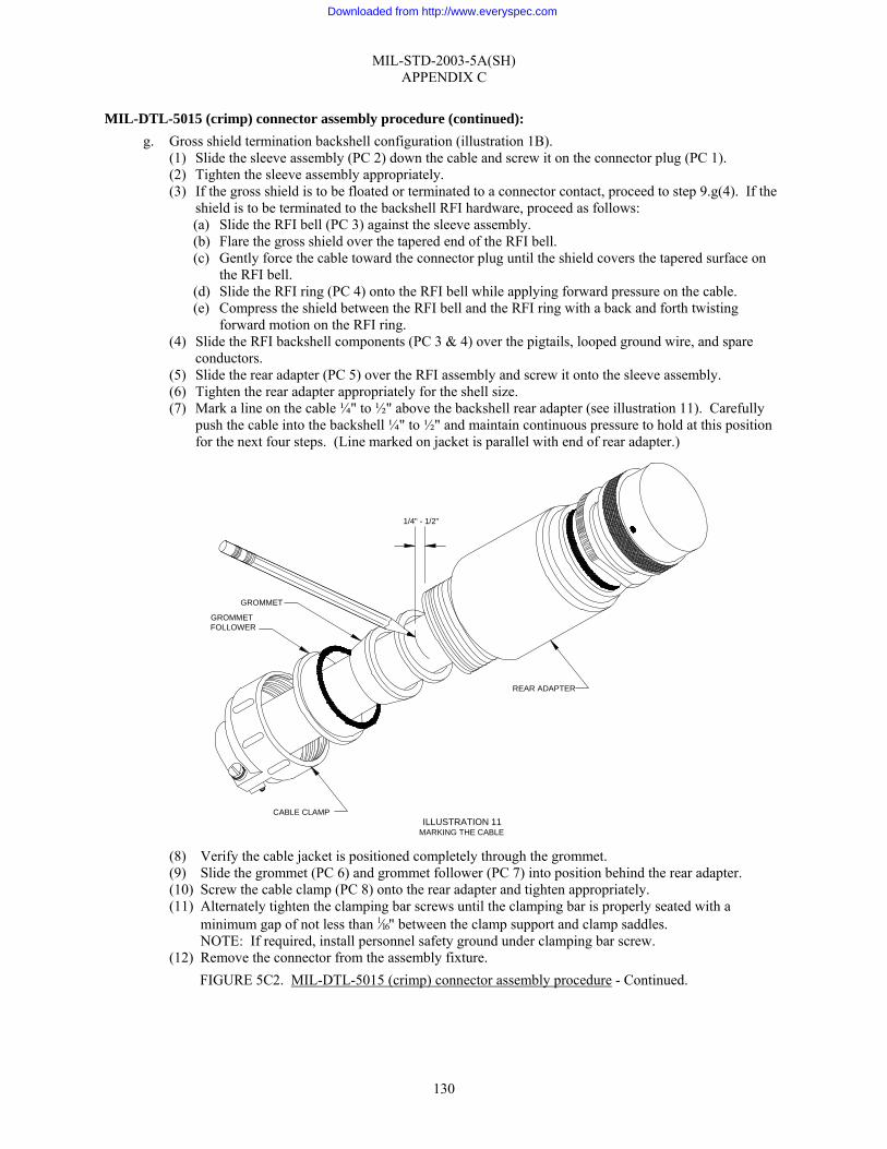
MIL-STD-2003-5A(SH) APPENDIX C
130
MIL-DTL-5015 (crimp) connector assembly procedure (continued): g. Gross shield termination backshell configuration (illustration 1B).
(1) Slide the sleeve assembly (PC 2) down the cable and screw it on the connector plug (PC 1). (2) Tighten the sleeve assembly appropriately. (3) If the gross shield is to be floated or terminated to a connector contact, proceed to step 9.g(4). If the
shield is to be terminated to the backshell RFI hardware, proceed as follows: (a) Slide the RFI bell (PC 3) against the sleeve assembly. (b) Flare the gross shield over the tapered end of the RFI bell. (c) Gently force the cable toward the connector plug until the shield covers the tapered surface on
the RFI bell. (d) Slide the RFI ring (PC 4) onto the RFI bell while applying forward pressure on the cable. (e) Compress the shield between the RFI bell and the RFI ring with a back and forth twisting
forward motion on the RFI ring. (4) Slide the RFI backshell components (PC 3 & 4) over the pigtails, looped ground wire, and spare
conductors. (5) Slide the rear adapter (PC 5) over the RFI assembly and screw it onto the sleeve assembly. (6) Tighten the rear adapter appropriately for the shell size. (7) Mark a line on the cable ¼" to ½" above the backshell rear adapter (see illustration 11). Carefully
push the cable into the backshell ¼" to ½" and maintain continuous pressure to hold at this position for the next four steps. (Line marked on jacket is parallel with end of rear adapter.)
(8) Verify the cable jacket is positioned completely through the grommet. (9) Slide the grommet (PC 6) and grommet follower (PC 7) into position behind the rear adapter. (10) Screw the cable clamp (PC 8) onto the rear adapter and tighten appropriately. (11) Alternately tighten the clamping bar screws until the clamping bar is properly seated with a
minimum gap of not less than 1⁄16" between the clamp support and clamp saddles. NOTE: If required, install personnel safety ground under clamping bar screw.
(12) Remove the connector from the assembly fixture. FIGURE 5C2. MIL-DTL-5015 (crimp) connector assembly procedure - Continued.
GROMMETFOLLOWER
ILLUSTRATION 11MARKING THE CABLE
GROMMET
CABLE CLAMP
REAR ADAPTER
1/4" - 1/2"
Downloaded from http://www.everyspec.com
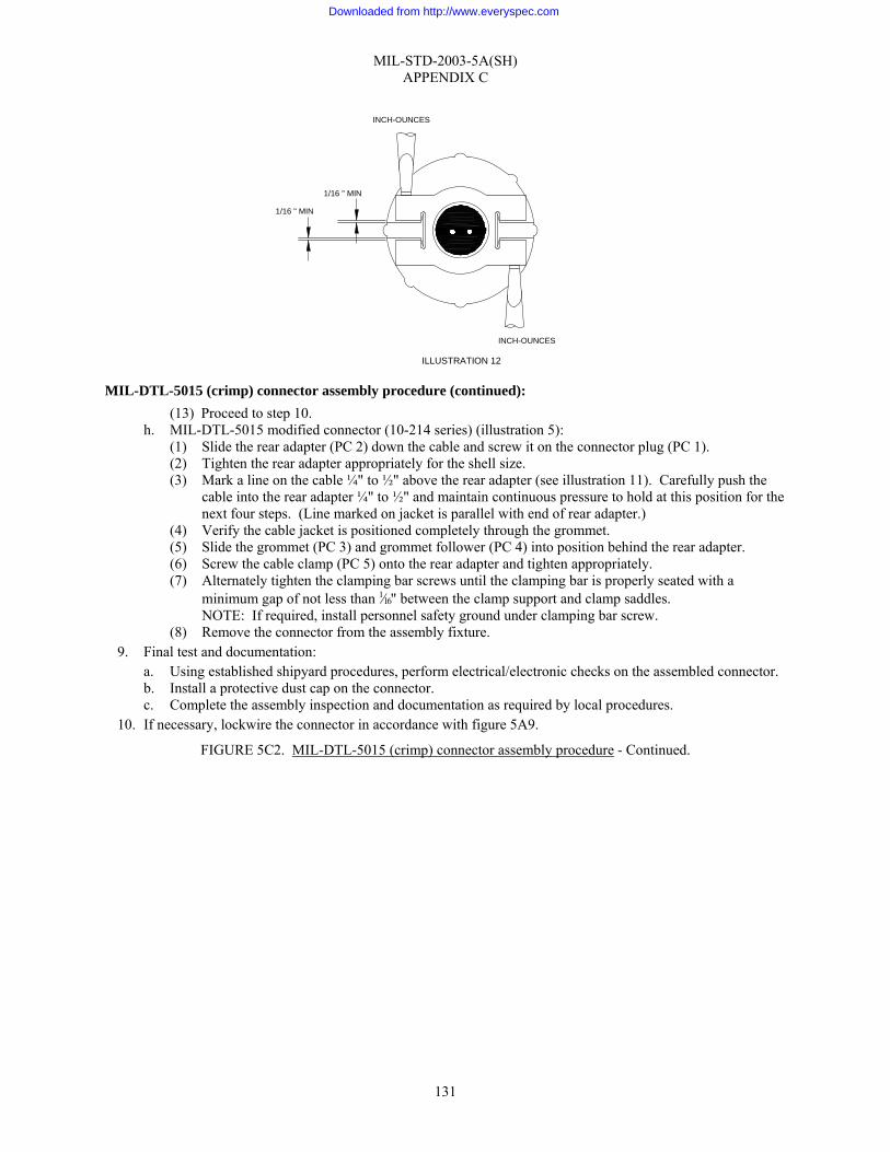
MIL-STD-2003-5A(SH) APPENDIX C
131
MIL-DTL-5015 (crimp) connector assembly procedure (continued): (13) Proceed to step 10.
h. MIL-DTL-5015 modified connector (10-214 series) (illustration 5): (1) Slide the rear adapter (PC 2) down the cable and screw it on the connector plug (PC 1). (2) Tighten the rear adapter appropriately for the shell size. (3) Mark a line on the cable ¼" to ½" above the rear adapter (see illustration 11). Carefully push the
cable into the rear adapter ¼" to ½" and maintain continuous pressure to hold at this position for the next four steps. (Line marked on jacket is parallel with end of rear adapter.)
(4) Verify the cable jacket is positioned completely through the grommet. (5) Slide the grommet (PC 3) and grommet follower (PC 4) into position behind the rear adapter. (6) Screw the cable clamp (PC 5) onto the rear adapter and tighten appropriately. (7) Alternately tighten the clamping bar screws until the clamping bar is properly seated with a
minimum gap of not less than 1⁄16" between the clamp support and clamp saddles. NOTE: If required, install personnel safety ground under clamping bar screw.
(8) Remove the connector from the assembly fixture. 9. Final test and documentation:
a. Using established shipyard procedures, perform electrical/electronic checks on the assembled connector. b. Install a protective dust cap on the connector. c. Complete the assembly inspection and documentation as required by local procedures.
10. If necessary, lockwire the connector in accordance with figure 5A9.
FIGURE 5C2. MIL-DTL-5015 (crimp) connector assembly procedure - Continued.
1/16 " MIN
1/16 " MIN
INCH-OUNCES
INCH-OUNCES
ILLUSTRATION 12
Downloaded from http://www.everyspec.com

MIL-STD-2003-5A(SH) APPENDIX D
132
GROUP 5D - MIL-DTL-26482 CONNECTORS
D.1 SCOPE
D.1.1 Scope. This appendix describes procedures for the preparation of MIL-DTL-26482 Connector Assembly.
D.2 APPLICABLE DOCUMENTS
D.2.1 General. The documents listed in this section are specified in this appendix. This section does not include documents cited in other sections of this standard or recommended for additional information or as examples. While every effort has been made to ensure the completeness of this list, document users are cautioned that they must meet all specified requirements of documents cited in this appendix, whether or not they are listed.
D.2.2 Government documents.
D.2.2.1 Specifications, standards, and handbooks. The following specifications, standards, and handbooks form a part of this document to the extent specified herein. Unless otherwise specified, the issues of these documents are those cited in the solicitation or contract.
DEPARTMENT OF DEFENSE SPECIFICATIONS
MIL-DTL-26482 - Connectors, Electrical, (Circular, Miniature, Quick Disconnect, Environment Resisting), Receptacles and Plugs, General Specification for
DEPARTMENT OF DEFENSE STANDARDS
MS3111 - Connectors, Plug, Electrical, Solder Type, Cable Connecting, Bayonet Coupling, Classes E, F, J, and P, Series 1
MS3116 - Connectors, Plug, Electric, Series 1, Solder Type, Straight, Bayonet Coupling
MS3121 - Connectors, Plug, Electrical, Crimp Type, Cable-Connecting, Bayonet Coupling, Classes E, F and P
MS3126 - Connectors, Plug, Electrical, Crimp Type, Straight, Bayonet Coupling
MS3144 - Connector, Receptacle, Electric Crimp Type, Jam Nut Mounting, Push-Pull Coupling Series 2 (Class E and J)
MS3471 Connectors, Receptacle, Electrical, Series II, Crimp Type, Cable Connecting, Bayonet Coupling, Classes A, L and W
MS3475 - Connectors, Plug, Electrical, RFI Shielded, Series II, Crimp Type, Bayonet Coupling, Classes L and W
MS3476 - Connectors, Plug, Electric, Series 2, Crimp Type, Bayonet Coupling, Classes A, L, S, and W
MS27488 - Plug, End Seal, Electrical Connector
(Copies of these documents are available online at http://assist.daps.dla.mil/quicksearch/ or from the Standardization Document Order Desk, 700 Robbins Avenue, Building 4D, Philadelphia, PA 19111-5094.)
D.2.3 Non-Government publications. The following documents form a part of this document to the extent specified herein. Unless otherwise specified, the issues of these documents are those cited in the solicitation or contract.
SAE INTERNATIONAL
SAE-AS31971 - Gage Pin for Socket Contact Engagement Test
Downloaded from http://www.everyspec.com
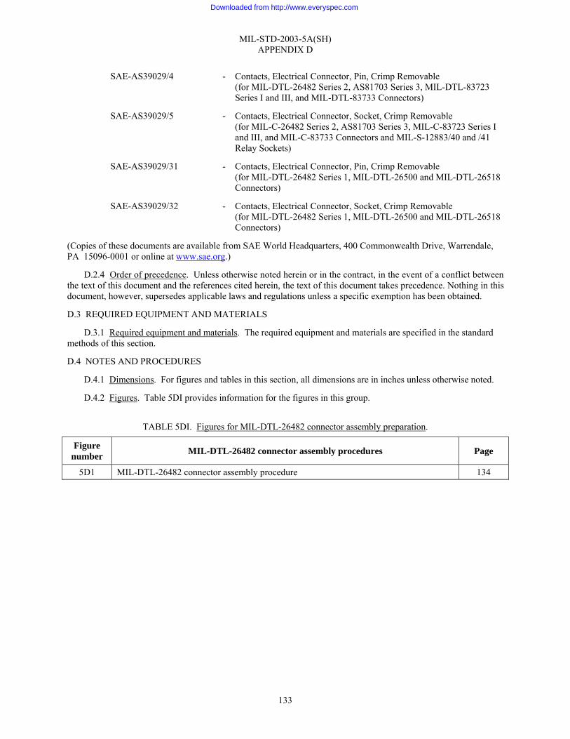
MIL-STD-2003-5A(SH) APPENDIX D
133
SAE-AS39029/4 - Contacts, Electrical Connector, Pin, Crimp Removable (for MIL-DTL-26482 Series 2, AS81703 Series 3, MIL-DTL-83723 Series I and III, and MIL-DTL-83733 Connectors)
SAE-AS39029/5 - Contacts, Electrical Connector, Socket, Crimp Removable (for MIL-C-26482 Series 2, AS81703 Series 3, MIL-C-83723 Series I and III, and MIL-C-83733 Connectors and MIL-S-12883/40 and /41 Relay Sockets)
SAE-AS39029/31 - Contacts, Electrical Connector, Pin, Crimp Removable (for MIL-DTL-26482 Series 1, MIL-DTL-26500 and MIL-DTL-26518 Connectors)
SAE-AS39029/32 - Contacts, Electrical Connector, Socket, Crimp Removable (for MIL-DTL-26482 Series 1, MIL-DTL-26500 and MIL-DTL-26518 Connectors)
(Copies of these documents are available from SAE World Headquarters, 400 Commonwealth Drive, Warrendale, PA 15096-0001 or online at www.sae.org.)
D.2.4 Order of precedence. Unless otherwise noted herein or in the contract, in the event of a conflict between the text of this document and the references cited herein, the text of this document takes precedence. Nothing in this document, however, supersedes applicable laws and regulations unless a specific exemption has been obtained.
D.3 REQUIRED EQUIPMENT AND MATERIALS
D.3.1 Required equipment and materials. The required equipment and materials are specified in the standard methods of this section.
D.4 NOTES AND PROCEDURES
D.4.1 Dimensions. For figures and tables in this section, all dimensions are in inches unless otherwise noted.
D.4.2 Figures. Table 5DI provides information for the figures in this group.
TABLE 5DI. Figures for MIL-DTL-26482 connector assembly preparation.
Figure number MIL-DTL-26482 connector assembly procedures Page
5D1 MIL-DTL-26482 connector assembly procedure 134
Downloaded from http://www.everyspec.com

MIL-STD-2003-5A(SH) APPENDIX D
134
MIL-DTL-26482 connector assembly procedure: Applicable connectors: MS3111 MS3116 MS3121 MS3126 MS3144 MS3471 MS3475 MS3476 NOTE: This procedure covers series 1 connectors, which have solder or front release crimp contacts, and series 2 connectors, which have rear release crimp contacts.
1. Visual inspection and verification: a. Disassemble the connector/backshell assembly. b. Verify that the connector is of the correct type and configuration for the cable being terminated in
accordance with the system cabling diagram. c. Verify that the backshell configuration is of the correct type as specified on the system cabling diagram. d. Verify that all component parts of the connector and backshell hardware are present (see illustration 1 for
a typical connector/backshell configuration). Reference: MIL-DTL-26482 for connector and backshell configurations.
FIGURE 5D1. MIL-DTL-26482 connector assembly procedure.
PC 1 CONNECTOR
PC 2 GROMMET
PC 3 GROMMET FOLLOWER(TAPERED SLEEVE)
PC 4 CABLE CLAMP (CLASS F)
PC 4 CABLE CLAMP (CLASS B)
PC 4 BACKSHELL (CLASS A)
ILLUSTRATION 1MIL-DTL-26482 TYPICAL CONNECTOR/BACKSHELL CONFIGURATION
PC 4 GROMMET NUT (CLASS E)
Downloaded from http://www.everyspec.com

MIL-STD-2003-5A(SH) APPENDIX D
135
MIL-DTL-26482 connector assembly procedure (continued): e. Visually inspect the components for damage such as deformed parts, gouges, damaged threads, cut O-
rings, burrs, or surface damage. f. Verify that the series 1 crimp pin contacts conform to SAE-AS39029/31, series 1 crimp socket contacts
conform to SAE-AS39029/32, series 2 crimp pin contacts conform to SAE-AS39029/4, or series 2 crimp socket contacts conform to SAE-AS39029/5 and are the correct size and type for the connector being assembled.
g. If the conductors are re-twisted during lead preparation, ensure they are twisted as tight as originally constructed, the natural lay of the conductor is maintained, and the conductors will fit inside the contact barrel.
2. Prepare the cable in accordance with figure 5A1. a. The grommet (PC 2, illustration 1) is designed to fit around individual conductors on Classes E and F and
therefore cannot be placed on the cable until individual conductors have been exposed in the cable. 3. Insertion setup: Owing to the many possible variations for acceptable tooling for contact insertion and
soldering, no specification is made as to a particular type. The criteria which are desirable for an acceptable assembly fixture are as follows: • A dummy receptacle, without connector insert, to hold the connector being worked on securely or a
clamping device that will not damage the connector. • A cable clamping fixture to hold the cable in a secure, fixed relationship to the connector while
permitting access to the rear face of the connector for the contact insertion tool or soldering iron. • A device for holding the wire bundle out of the work area. • Contact insertion guides for socket contacts to prevent the collapse of adjacent insert holes as the
connector is gradually filled with contacts (this facet becomes increasingly important as the contact density increases). A recommended assembly fixture is shown in illustration 2. NOTE: Equivalent tooling from alternate sources is acceptable; however, the use of other tools may affect the procedural steps outlined below.
a. Secure the assembly fixture to a vise or similar holding device in order to provide a stable work area. b. Use of this assembly fixture negates the need for a dummy receptacle. Illustration 3 illustrates how the
connector is firmly seated in the connector clamp. c. Seat the connector in the connector clamp and adjust the wing nuts to secure it in place.
FIGURE 5D1. MIL-DTL-26482 connector assembly procedure - Continued.
Downloaded from http://www.everyspec.com

MIL-STD-2003-5A(SH) APPENDIX D
136
MIL-DTL-26482 connector assembly procedure (continued): d. Place the prepared cable in the fixture clamp so that the first contacts to be inserted/soldered will be at
the back of the connector as it is held in the connector clamp. e. Position the cable at a position similar to the backshell design (i.e., 45 degrees, 90 degrees, or straight).
Secure the cable in the fixture clamp (illustration 4A). f. Position the connector so that the connector-to-cable jacket distance is that measured in step 9.b of figure
5A1. Rotate the connector to align the keyway position in proper relationship to the backshell. (illustration 4B).
g. Route the individual conductors per the applicable wiring table. Ensure that the longest routed conductor has sufficient length at the required position termination prior to cutting any conductor (illustration 4C).
FIGURE 5D1. MIL-DTL-26482 connector assembly procedure - Continued.
FIXTURE CLAMP
ANGLE ADJUSTED TO BACKSHELLCONFIGURATION (I.E., STRAIGHT, 45°, OR 90°)
CONNECTORCLAMP
SEE ILLUSTRATION 3
ILLUSTRATION 2ASSEMBLY FIXTURE
ILLUSTRATION 3CONNECTOR SEATED IN ASSEMBLY FIXTURE
CONNECTORCLAMP
Downloaded from http://www.everyspec.com
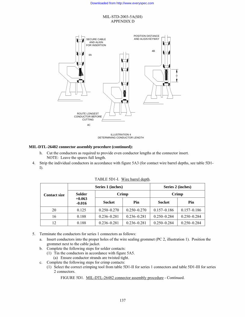
MIL-STD-2003-5A(SH) APPENDIX D
137
MIL-DTL-26482 connector assembly procedure (continued): h. Cut the conductors as required to provide even conductor lengths at the connector insert.
NOTE: Leave the spares full length. 4. Strip the individual conductors in accordance with figure 5A3 (for contact wire barrel depths, see table 5D1-
I).
TABLE 5D1-I. Wire barrel depth.
Series 1 (inches) Series 2 (inches)
Crimp Crimp Contact size Solder +0.063 -0.016 Socket Pin Socket Pin
20 0.125 0.250–0.270 0.250–0.270 0.157–0.186 0.157–0.186 16 0.188 0.236–0.281 0.236–0.281 0.250–0.284 0.250–0.284 12 0.188 0.236–0.281 0.236–0.281 0.250–0.284 0.250–0.284
5. Terminate the conductors for series 1 connectors as follows:
a. Insert conductors into the proper holes of the wire sealing grommet (PC 2, illustration 1). Position the grommet next to the cable jacket.
b. Complete the following steps for solder contacts: (1) Tin the conductors in accordance with figure 5A5.
(a) Ensure conductor strands are twisted tight. c. Complete the following steps for crimp contacts:
(1) Select the correct crimping tool from table 5D1-II for series 1 connectors and table 5D1-III for series 2 connectors.
FIGURE 5D1. MIL-DTL-26482 connector assembly procedure - Continued.
ROUTE LONGESTCONDUCTOR BEFORE
CUTTING
SECURE CABLEAND ALIGN
FOR INSERTION
POSITION DISTANCEAND ALIGN KEYWAY
4C
4A4B
D
ILLUSTRATION 4DETERMINING CONDUCTOR LENGTH
Downloaded from http://www.everyspec.com
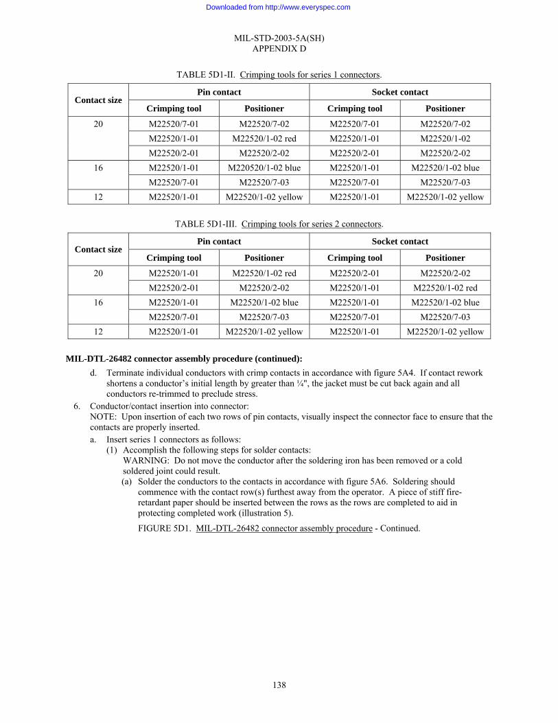
MIL-STD-2003-5A(SH) APPENDIX D
138
TABLE 5D1-II. Crimping tools for series 1 connectors.
Pin contact Socket contact Contact size
Crimping tool Positioner Crimping tool Positioner
M22520/7-01 M22520/7-02 M22520/7-01 M22520/7-02 M22520/1-01 M22520/1-02 red M22520/1-01 M22520/1-02
20
M22520/2-01 M22520/2-02 M22520/2-01 M22520/2-02 M22520/1-01 M220520/1-02 blue M22520/1-01 M22520/1-02 blue 16 M22520/7-01 M22520/7-03 M22520/7-01 M22520/7-03
12 M22520/1-01 M22520/1-02 yellow M22520/1-01 M22520/1-02 yellow
TABLE 5D1-III. Crimping tools for series 2 connectors.
Pin contact Socket contact Contact size
Crimping tool Positioner Crimping tool Positioner
M22520/1-01 M22520/1-02 red M22520/2-01 M22520/2-02 20 M22520/2-01 M22520/2-02 M22520/1-01 M22520/1-02 red M22520/1-01 M22520/1-02 blue M22520/1-01 M22520/1-02 blue 16 M22520/7-01 M22520/7-03 M22520/7-01 M22520/7-03
12 M22520/1-01 M22520/1-02 yellow M22520/1-01 M22520/1-02 yellow MIL-DTL-26482 connector assembly procedure (continued):
d. Terminate individual conductors with crimp contacts in accordance with figure 5A4. If contact rework shortens a conductor’s initial length by greater than ¼", the jacket must be cut back again and all conductors re-trimmed to preclude stress.
6. Conductor/contact insertion into connector: NOTE: Upon insertion of each two rows of pin contacts, visually inspect the connector face to ensure that the contacts are properly inserted. a. Insert series 1 connectors as follows:
(1) Accomplish the following steps for solder contacts: WARNING: Do not move the conductor after the soldering iron has been removed or a cold soldered joint could result. (a) Solder the conductors to the contacts in accordance with figure 5A6. Soldering should
commence with the contact row(s) furthest away from the operator. A piece of stiff fire-retardant paper should be inserted between the rows as the rows are completed to aid in protecting completed work (illustration 5).
FIGURE 5D1. MIL-DTL-26482 connector assembly procedure - Continued.
Downloaded from http://www.everyspec.com

MIL-STD-2003-5A(SH) APPENDIX D
139
(2) Accomplish the following steps for crimp contacts:
NOTE: Adjust the assembly fixture as required during the insertion process to ease stress on the conductors. (a) Select the proper insertion tool from table 5D1-IV.
TABLE 5D1-IV. Insertion and removal tools.
Pin contact Socket contact Contact size
Insertion tool Removal tool Insertion tool Removal tool
MS81969/17-03 MS84969/17-03 20 MS84969/14-02
MS81969/19-07 MS84969/14-02
MS81969/19-07
MS81969/17-04 MS84969/14-03 16 MS81969/14-03
MS81969/19-08 MS84969/17-04
MS81969/19-08
MS81969/17-05 MS84969/14-04 12 MS84969/14-04
MS81969/19-09 MS84969/17-05
MS81969/19-09
(b) Insert a wired contact into the rear of the insert. (c) Seat the contact by positioning the insertion tool around the rear of the contact shoulder with a
slight angle toward the contact to assure a firm grip (see illustration 6). FIGURE 5D1. MIL-DTL-26482 connector assembly procedure - Continued.
ILLUSTRATION 5PROTECTING SOLDERED CONTACTS
SOLDERED CONTACTS
WORK IN PROGRESS
STIFF PAPER
Downloaded from http://www.everyspec.com

MIL-STD-2003-5A(SH) APPENDIX D
140
MIL-DTL-26482 connector assembly procedure (continued): 1 Push the contact straight into the connector with a firm, steady pressure until the contact
bottoms. 2 The contact shoulder provides a positive stop.
(d) Move the insertion tool back away from the contact before sliding it straight up along the wire insulation until it clears the insert. 1 Slightly pull on inserted lead to ensure contact has locked in connector.
b. Accomplish the following steps for series 2 connectors: NOTE: Adjust the assembly fixture as required during the insertion process to ease stress on the conductors. (1) Select the proper insertion tool from table 5D1-V.
FIGURE 5D1. MIL-DTL-26482 connector assembly procedure - Continued.
ILLUSTRATION 6CONTACT INSERTION (SERIES 1)
INSERTION TOOL
CONTACT
Downloaded from http://www.everyspec.com
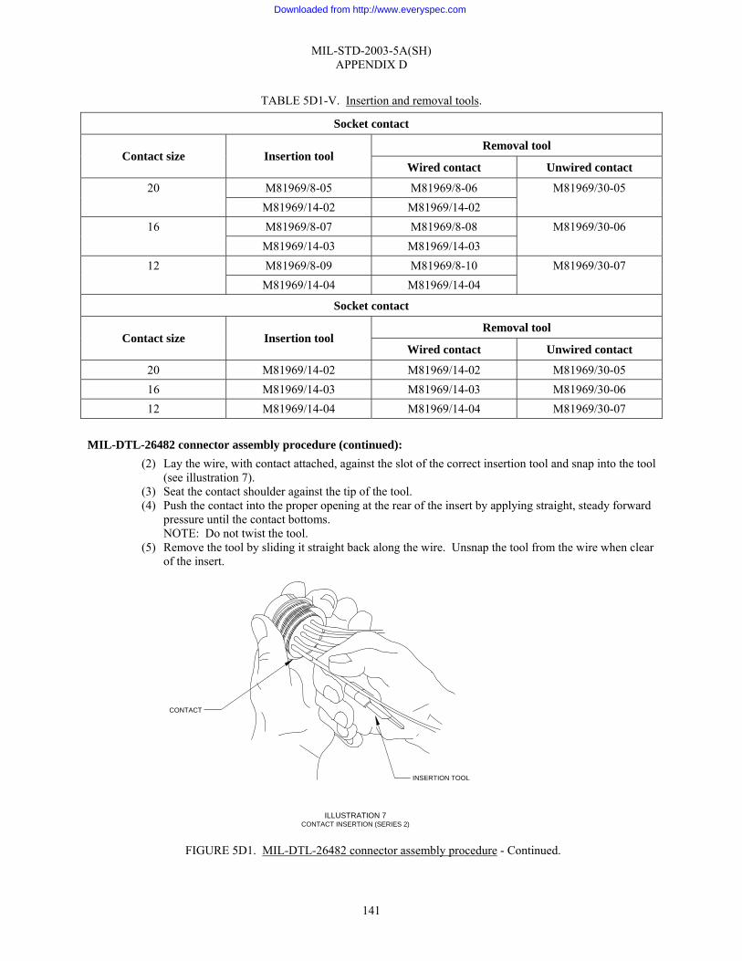
MIL-STD-2003-5A(SH) APPENDIX D
141
TABLE 5D1-V. Insertion and removal tools.
Socket contact
Removal tool Contact size Insertion tool
Wired contact Unwired contact
M81969/8-05 M81969/8-06 20 M81969/14-02 M81969/14-02
M81969/30-05
M81969/8-07 M81969/8-08 16 M81969/14-03 M81969/14-03
M81969/30-06
M81969/8-09 M81969/8-10 12 M81969/14-04 M81969/14-04
M81969/30-07
Socket contact
Removal tool Contact size Insertion tool
Wired contact Unwired contact
20 M81969/14-02 M81969/14-02 M81969/30-05 16 M81969/14-03 M81969/14-03 M81969/30-06 12 M81969/14-04 M81969/14-04 M81969/30-07
MIL-DTL-26482 connector assembly procedure (continued):
(2) Lay the wire, with contact attached, against the slot of the correct insertion tool and snap into the tool (see illustration 7).
(3) Seat the contact shoulder against the tip of the tool. (4) Push the contact into the proper opening at the rear of the insert by applying straight, steady forward
pressure until the contact bottoms. NOTE: Do not twist the tool.
(5) Remove the tool by sliding it straight back along the wire. Unsnap the tool from the wire when clear of the insert.
FIGURE 5D1. MIL-DTL-26482 connector assembly procedure - Continued.
ILLUSTRATION 7CONTACT INSERTION (SERIES 2)
CONTACT
INSERTION TOOL
Downloaded from http://www.everyspec.com

MIL-STD-2003-5A(SH) APPENDIX D
142
MIL-DTL-26482 connector assembly procedure (continued): (a) Slightly pull on inserted conductor to ensure contact has locked in connector.
c. Ensure that the shield ground wire (if terminated to a contact) is inserted in its proper location. d. Insert unwired contacts into all empty holes in the connector insert. e. Insert sealing plugs meeting the requirements of MS27488 into all unwired contact holes for series 1,
Classes E and F, and series 2, Classes L, R, and A connectors. f. Remove the connector from the connector clamp. g. Conduct a visual check of the connector and verify wire location against the wiring table. Ensure no
debris is inside socket contacts. 7. Contact removal procedures (as required):
a. Conduct a visual inspection of the connector face to identify any unseated contacts. b. If required to remove unseated contacts, proceed as follows:
(1) Remove unseated series 1 crimp contacts as follows: (a) Select the proper removal tool from table 5D1-IV.
FIGURE 5D1. MIL-DTL-26482 connector assembly procedure - Continued.
ILLUSTRATION 7 (CONTINUED)CONTACT INSERTION (SERIES 2)
Downloaded from http://www.everyspec.com

MIL-STD-2003-5A(SH) APPENDIX D
143
MIL-DTL-26482 connector assembly procedure (continued): (b) Insert the removal tool into the connector face, placing the sleeve of the tool over the contact to
be removed. (c) Using straight, forward motion, push and slightly rotate the tool until the sleeve bottoms in the
insert. (d) Push the removal tool thrust collar forward, which moves the contact back through the insert,
exposing it for easy hand removal. (e) Remove the removal tool from the connector.
(2) Remove unseated series 2 contacts as follows: (a) Select the correct removal tool from table 5D1-V. (b) Lay the slot of the tool against the wire of the contact to be removed leaving ½" from the tool end
to the rear of the connector. (c) Squeeze the wire firmly into the tool between the thumb and forefinger about ½" from the tool
tip. (d) Slide the tool down along the wire and slowly into the insert until positive resistance is felt.
WARNING: Do not twist or turn the tool. (e) Pull both the tool and wired contact out of the connector.
c. Reinsert all extracted contacts. d. If a contact fails to reseat after three insertion attempts, replace the offending contact. If the same contact
location continues to give difficulty, the connector is probably damaged or faulty and must be replaced. 8. Backshell assembly:
NOTE: The following assembly procedure is based on the nomenclature and hardware configuration depicted in illustration 1. Variations may occur and cause minor deviations from this procedure. If this situation occurs, the manufacturer’s assembly instructions should be followed. a. Fold the spare wires back one-half the distance between the connector and the jacket end. b. Slide a 1" long piece of ¼" shrink tubing over each folded pair and shrink in place. c. Lightly coat the threads of each backshell part with petrolatum (AN-P-51 or equivalent) just prior to
using. d. Loosen the fixture clamp from the assembly fixture. e. For class “A” connectors:
(1) Slide the backshell over the conductors and tighten appropriately. f. For Class “E” and “F” connectors:
(1) Slide the grommet (PC 2, illustration 1) over the wire bundle. (2) Slide the tapered sleeve (PC 3, illustration 1) and grommet nut (PC 4, illustration 1) over the
grommet and tighten the grommet nut. (a) Ensure the tapered sleeve is not cocked in the nut.
FIGURE 5D1. MIL-DTL-26482 connector assembly procedure - Continued.
Downloaded from http://www.everyspec.com

MIL-STD-2003-5A(SH) APPENDIX D
144
MIL-DTL-26482 connector assembly procedure (continued): g. If a cable clamp is attached (class “B” or “F”), attach the clamp to the connector assembly and tighten
appropriately. h. Alternately tighten the clamping bar screws until the clamping bar is properly seated with a minimum
gap of not less than 1⁄16" between the clamp support and clamp saddle (illustration 8). NOTE: If required, install personnel safety ground under clamping bar screw.
i. Remove the connector from the assembly fixture.
9. Final test and documentation: a. Using established shipyard procedures, perform electrical/electronic checks on the assembled connector. b. Install a protective dust cap on the connector. c. Complete the assembly inspection and documentation as required by local procedures.
10. If necessary, lockwire the connector in accordance with figure 5A9.
FIGURE 5D1. MIL-DTL-26482 connector assembly procedure - Continued.
ILLUSTRATION 8CLAMP SCREW GAP
1/16 " MIN
1/16 " MIN
INCH-OUNCES
INCH-OUNCES
Downloaded from http://www.everyspec.com
MIL-STD-2003-5A(SH) APPENDIX E
145
GROUP 5E - MIL-DTL-28840 CONNECTORS
E.1 SCOPE
E.1.1 Scope. This appendix provides instructions for preparing cable in preparation for MIL-DTL-28840 connectors and assembly of such connectors.
E.2 APPLICABLE DOCUMENTS
E.2.1 General. The documents listed in this section are specified in this appendix. This section does not include documents cited in other sections of this standard or recommended for additional information or as examples. While every effort has been made to ensure the completeness of this list, document users are cautioned that they must meet all specified requirements of documents cited in this appendix, whether or not they are listed.
E.2.2 Government documents.
E.2.2.1 Specifications, standards, and handbooks. The following specifications, standards, and handbooks form a part of this document to the extent specified herein. Unless otherwise specified, the issues of these documents are those cited in the solicitation or contract.
DEPARTMENT OF DEFENSE SPECIFICATIONS
MIL-DTL-28840 - Connectors, Electrical, Circular, Threaded, High Density, High Shock, Shipboard, Class D, General Specification for
DEPARTMENT OF DEFENSE STANDARDS
MS27488 - Plug, End Seal, Electrical Connector
(Copies of these documents are available online at http://assist.daps.dla.mil/quicksearch/ or from the Standardization Document Order Desk, 700 Robbins Avenue, Building 4D, Philadelphia, PA 19111-5094.)
E.2.3 Non-Government publications. The following documents form a part of this document to the extent specified herein. Unless otherwise specified, the issues of these documents are those cited in the solicitation or contract.
SAE INTERNATIONAL
SAE-AS31971 - Gage Pin for Socket Contact Engagement Test
SAE-AS39029/83 - Contacts, Electrical Connector, Pin, Crimp Removable (for MIL-C-28840 Connectors)
SAE-AS39029/84 - Contacts, Electrical Connector, Socket, Crimp Removable (For MIL-C-28840 Connectors)
(Copies of these documents are available from SAE World Headquarters, 400 Commonwealth Drive, Warrendale, PA 15096-0001 or online at www.sae.org.)
E.2.4 Order of precedence. Unless otherwise noted herein or in the contract, in the event of a conflict between the text of this document and the references cited herein, the text of this document takes precedence. Nothing in this document, however, supersedes applicable laws and regulations unless a specific exemption has been obtained.
E.3 REQUIRED EQUIPMENT AND MATERIALS
E.3.1 Required equipment and materials. The required equipment and materials are specified in the standard methods of this section.
E.4 NOTES AND PROCEDURES
E.4.1 Dimensions. For figures and tables in this section, all dimensions are in inches unless otherwise noted.
Downloaded from http://www.everyspec.com

MIL-STD-2003-5A(SH) APPENDIX E
146
E.4.2 Figures. Table 5EI provides information for the figures in this group.
TABLE 5EI. Figures for MIL-DTL-28840 connector assembly preparation.
Figure number MIL-DTL-28840 connector assembly procedures Page
5E1 MIL-C-28840 connector assembly procedure 147
Downloaded from http://www.everyspec.com
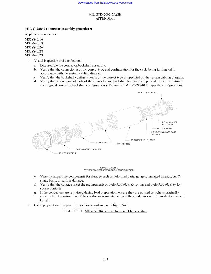
MIL-STD-2003-5A(SH) APPENDIX E
147
MIL-C-28840 connector assembly procedure: Applicable connectors: MS28840/16 MS28840/18 MS28840/26 MS28840/28 MS28840/29
1. Visual inspection and verification: a. Disassemble the connector/backshell assembly. b. Verify that the connector is of the correct type and configuration for the cable being terminated in
accordance with the system cabling diagram. c. Verify that the backshell configuration is of the correct type as specified on the system cabling diagram. d. Verify that all component parts of the connector and backshell hardware are present. (See illustration 1
for a typical connector/backshell configuration.) Reference: MIL-C-28840 for specific configurations.
e. Visually inspect the components for damage such as deformed parts, gouges, damaged threads, cut O-
rings, burrs, or surface damage. f. Verify that the contacts meet the requirements of SAE-AS39029/83 for pin and SAE-AS39029/84 for
socket contacts. g. If the conductors are re-twisted during lead preparation, ensure they are twisted as tight as originally
constructed, the natural lay of the conductor is maintained, and the conductors will fit inside the contact barrel.
2. Cable preparation: Prepare the cable in accordance with figure 5A1.
FIGURE 5E1. MIL-C-28840 connector assembly procedure.
ILLUSTRATION 1TYPICAL CONNECTOR/BACKSHELL CONFIGURATION
PC 1 CONNECTOR
PC 2 BACKSHELL ADAPTER
PC 3 RFI BELLPC 4 RFI RING
PC 5 BACKSHELL SLEEVE
PC 6 SEALING HARDWAREWASHER
PC 7 GROMMET
PC 8 GROMMETFOLLOWER
PC 9 CABLE CLAMP
Downloaded from http://www.everyspec.com

MIL-STD-2003-5A(SH) APPENDIX E
148
MIL-C-28840 connector assembly procedure (continued): 3. Insertion setup: Owing to the many possible variations for acceptable designs for an assembly fixture, no
specification is made as to a particular type. The criteria, which are desirable for an acceptable assembly fixture, are as follows: • A dummy receptacle, without connector insert, to hold the connector being worked on securely or a
clamping device that will not damage the connector. • A cable clamping fixture (illustration 2) to hold the cable in a secure fixed relationship to the connector
while permitting access to the rear face of the connector for the contact insertion tool. • A device for holding the wire bundle out of the work area. The assembly fixture recommended is shown
in illustration 2. NOTE: Equivalent tooling from alternate sources is acceptable; however, the use of other tools may affect the procedural steps outlined below.
FIGURE 5E1. MIL-C-28840 connector assembly procedure - Continued.
FIXTURE CLAMP
ANGLE ADJUSTED TO BACKSHELLCONFIGURATION (I.E., STRAIGHT, 45°, OR 90°)
CONNECTORCLAMP
SEE ILLUSTRATION 3
ILLUSTRATION 2ASSEMBLY FIXTURE
Downloaded from http://www.everyspec.com

MIL-STD-2003-5A(SH) APPENDIX E
149
MIL-C-28840 connector assembly procedure (continued): a. Secure the assembly fixture to a vice or similar holding device in order to provide a stable work area. b. Use of this assembly fixture negates the need for a dummy receptacle. Illustration 3 illustrates how the
connector is firmly seated in the connector clamp. c. Seat the connector in the connector clamp and adjust the wing nuts to secure it in place. d. Place the prepared cable in the fixture clamp so that the first contacts to be inserted will be at the back of
the connector as it is held in the connector clamp. e. Position the cable at the angle similar to the backshell design (i.e., 45 degrees, 90 degrees, or straight).
Secure the cable in the fixture clamp (illustration 4A). f. Position the connector so that the connector-to-cable jacket distance is that measured in step 9.b of figure
5A1. Rotate the connector to align the keyway position in proper relationship to the backshell (illustration 4B).
g. Route the individual conductors in accordance with the applicable wiring table. Ensure that the longest routed conductor has sufficient length at the required position termination prior to cutting any conductor (illustration 4C).
FIGURE 5E1. MIL-C-28840 connector assembly procedure - Continued.
ILLUSTRATION 3CONNECTOR SEATED IN ASSEMBLY FIXTURE
CONNECTORCLAMP
Downloaded from http://www.everyspec.com
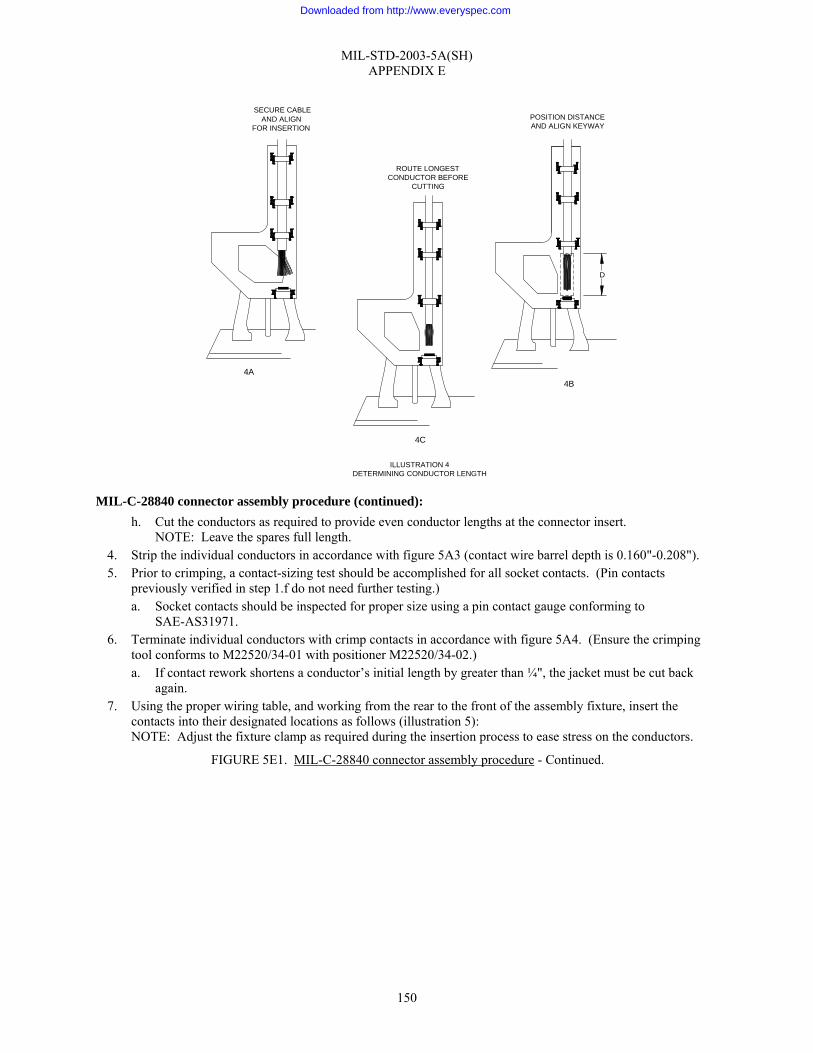
MIL-STD-2003-5A(SH) APPENDIX E
150
MIL-C-28840 connector assembly procedure (continued): h. Cut the conductors as required to provide even conductor lengths at the connector insert.
NOTE: Leave the spares full length. 4. Strip the individual conductors in accordance with figure 5A3 (contact wire barrel depth is 0.160"-0.208"). 5. Prior to crimping, a contact-sizing test should be accomplished for all socket contacts. (Pin contacts
previously verified in step 1.f do not need further testing.) a. Socket contacts should be inspected for proper size using a pin contact gauge conforming to
SAE-AS31971. 6. Terminate individual conductors with crimp contacts in accordance with figure 5A4. (Ensure the crimping
tool conforms to M22520/34-01 with positioner M22520/34-02.) a. If contact rework shortens a conductor’s initial length by greater than ¼", the jacket must be cut back
again. 7. Using the proper wiring table, and working from the rear to the front of the assembly fixture, insert the
contacts into their designated locations as follows (illustration 5): NOTE: Adjust the fixture clamp as required during the insertion process to ease stress on the conductors.
FIGURE 5E1. MIL-C-28840 connector assembly procedure - Continued.
ROUTE LONGESTCONDUCTOR BEFORE
CUTTING
4A 4B
D
SECURE CABLEAND ALIGN
FOR INSERTION
4C
POSITION DISTANCEAND ALIGN KEYWAY
ILLUSTRATION 4DETERMINING CONDUCTOR LENGTH
Downloaded from http://www.everyspec.com
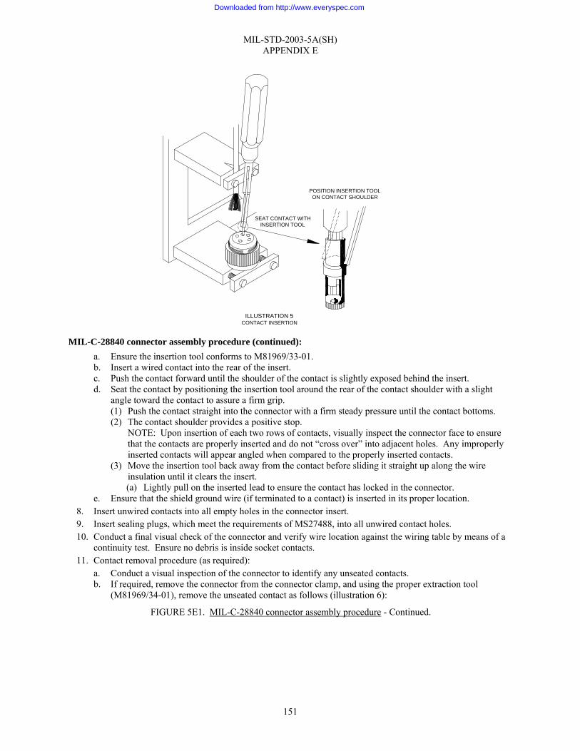
MIL-STD-2003-5A(SH) APPENDIX E
151
MIL-C-28840 connector assembly procedure (continued): a. Ensure the insertion tool conforms to M81969/33-01. b. Insert a wired contact into the rear of the insert. c. Push the contact forward until the shoulder of the contact is slightly exposed behind the insert. d. Seat the contact by positioning the insertion tool around the rear of the contact shoulder with a slight
angle toward the contact to assure a firm grip. (1) Push the contact straight into the connector with a firm steady pressure until the contact bottoms. (2) The contact shoulder provides a positive stop.
NOTE: Upon insertion of each two rows of contacts, visually inspect the connector face to ensure that the contacts are properly inserted and do not “cross over” into adjacent holes. Any improperly inserted contacts will appear angled when compared to the properly inserted contacts.
(3) Move the insertion tool back away from the contact before sliding it straight up along the wire insulation until it clears the insert. (a) Lightly pull on the inserted lead to ensure the contact has locked in the connector.
e. Ensure that the shield ground wire (if terminated to a contact) is inserted in its proper location. 8. Insert unwired contacts into all empty holes in the connector insert. 9. Insert sealing plugs, which meet the requirements of MS27488, into all unwired contact holes. 10. Conduct a final visual check of the connector and verify wire location against the wiring table by means of a
continuity test. Ensure no debris is inside socket contacts. 11. Contact removal procedure (as required):
a. Conduct a visual inspection of the connector to identify any unseated contacts. b. If required, remove the connector from the connector clamp, and using the proper extraction tool
(M81969/34-01), remove the unseated contact as follows (illustration 6):
FIGURE 5E1. MIL-C-28840 connector assembly procedure - Continued.
SEAT CONTACT WITHINSERTION TOOL
POSITION INSERTION TOOLON CONTACT SHOULDER
ILLUSTRATION 5CONTACT INSERTION
Downloaded from http://www.everyspec.com

MIL-STD-2003-5A(SH) APPENDIX E
152
MIL-C-28840 connector assembly procedure (continued): (1) Insert the extraction tool into the connector face and enclose the front of the contact with the tool. (2) Pushing with the rear of the tool to fully bottom the tool tip, rotate the tool rear slightly in the
clockwise direction. (3) Push the tool thrust sleeve forward moving the contact back through the insert. (4) Remove the contact from the rear of the connector and slowly remove the extraction tool from the
face of the contact. c. Reinsert all extracted contacts in accordance with step 7 and re-inspect the connector face. d. If a contact fails to reseat after three insertion attempts, replace the offending contact. If the same contact
location continues to give difficulty, the connector is probably damaged or faulty and must be replaced. e. Remove the connector from the connector clamp if not previously accomplished.
12. Backshell assembly: NOTE: The following assembly procedure is based on the nomenclature and hardware configuration depicted in illustration 1. Variations may occur and cause minor deviations from this procedure. If this situation occurs, the manufacturer’s assembly instructions should be followed. a. Fold spare wires back one-half the distance between the connector and the jacket end. b. Slide a 1" long piece of appropriately sized shrink tubing over each folded pair and shrink in place. c. Lightly coat the thread of each backshell part with petrolatum (AN-P-51 or equivalent) just prior to using. d. Position and lubricate all O-rings. e. Loosen the cable clamp on the assembly fixture. f. Slide the backshell adapter (PC 2, illustration 1) down the cable and screw it on the connector. Tighten
the adapter appropriately. FIGURE 5E1. MIL-C-28840 connector assembly procedure - Continued.
ILLUSTRATION 6REMOVING A CONTACT
CONNECTOR
EXTRACTION TOOL
Downloaded from http://www.everyspec.com

MIL-STD-2003-5A(SH) APPENDIX E
153
MIL-C-28840 connector assembly procedure (continued): g. If the gross shield is to be floated or terminated to a connector contact, proceed to step 12.h. If the shield
is to be terminated to the backshell RFI hardware, proceed as follows: (1) Slide the RFI bell (PC 3, illustration 1) against the backshell adapter. (2) Flare the gross shield over the tapered end of the RFI bell. (3) Gently force the cable toward the connector plug until the shield covers the tapered surface on the
RFI bell. (4) Slide the RFI ring (PC 4, illustration 1) onto the RFI bell while applying forward pressure on the
cable. (5) Compress the shield between the RFI bell and RFI ring with a back and forth twisting forward
motion on the RFI ring. h. Slide the RFI backshell components (PC 3 & 4, illustration 1) over the pigtails, looped ground wire, and
spare conductors. i. Slide the backshell sleeve (PC 5, illustration 1) over the RFI assembly and screw the sleeve onto the
adapter. j. Tighten the sleeve appropriately. k. Mark a line on the cable ¼"-½" above the backshell sleeve (see illustration 7). Carefully push the cable
into the backshell ¼"-½" and maintain continuous pressure to hold at this position for the next four steps. (Line marked on jacket is parallel with end of backshell sleeve.)
l. Verify the cable jacket is positioned completely through the grommet. m. Slide the sealing hardware washer (PC 6, illustration 1), grommet (PC 7, illustration 1) and grommet
follower (PC 8, illustration 1) into position behind the sleeve. n. Screw the cable clamp (PC 9, illustration 1) onto the sleeve and tighten appropriately. o. Alternately tighten the clamping bar screws until the appropriate gap is achieved (illustration 8).
NOTE: If required, install personnel safety ground under clamping bar screw. FIGURE 5E1. MIL-C-28840 connector assembly procedure - Continued.
ILLUSTRATION 7MARKING THE CABLE
CONNECTOR
BACKSHELLSLEEVE
SEALING HARDWAREWASHER
GROMMET
CABLE CLAMP
GROMMET FOLLOWER
1/4" - 1/2"
Downloaded from http://www.everyspec.com
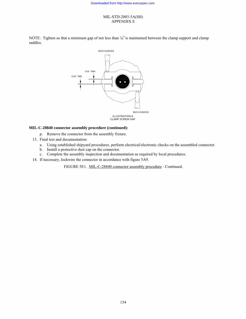
MIL-STD-2003-5A(SH) APPENDIX E
154
NOTE: Tighten so that a minimum gap of not less than 1⁄16" is maintained between the clamp support and clamp saddles.
MIL-C-28840 connector assembly procedure (continued): p. Remove the connector from the assembly fixture.
13. Final test and documentation: a. Using established shipyard procedures, perform electrical/electronic checks on the assembled connector. b. Install a protective dust cap on the connector. c. Complete the assembly inspection and documentation as required by local procedures.
14. If necessary, lockwire the connector in accordance with figure 5A9.
FIGURE 5E1. MIL-C-28840 connector assembly procedure - Continued.
ILLUSTRATION 8CLAMP SCREW GAP
1/16 " MIN
1/16 " MIN
INCH-OUNCES
INCH-OUNCES
Downloaded from http://www.everyspec.com

MIL-STD-2003-5A(SH) APPENDIX F
155
GROUP 5F - MIL-DTL-27599 CONNECTORS
F.1 SCOPE
F.1.1 Scope. This appendix provides instruction for preparing cable in preparation for MIL-DTL-27599 connectors and assembly of such connectors.
F.2 APPLICABLE DOCUMENTS
F.2.1 General. The documents listed in this section are specified in this appendix. This section does not include documents cited in other sections of this standard or recommended for additional information or as examples. While every effort has been made to ensure the completeness of this list, document users are cautioned that they must meet all specified requirements of documents cited in this appendix, whether or not they are listed.
F.2.2 Government documents.
F.2.2.1 Specifications, standards, and handbooks. The following specifications, standards, and handbooks form a part of this document to the extent specified herein. Unless otherwise specified, the issues of these documents are those cited in the solicitation or contract.
DEPARTMENT OF DEFENSE SPECIFICATIONS
MIL-DTL-5015 - Connectors, Electrical, Circular Threaded, AN Type, General Specification for
MIL-DTL-27599 - Connectors, Electrical, Circular, Miniature, High Density, Quick Disconnect, Environment Resistant, Solder Contacts, General Specification for
MIL-DTL-28840 - Connectors, Electrical, Circular, Threaded, High Density, High Shock, Shipboard, Class D, General Specification for
DEPARTMENT OF DEFENSE STANDARDS
MS20027 - Connectors, Line Plug, Electrical, Solder Type, Bayonet Coupling, Class T, Series I
MS20028 - Connectors, Plug, Electrical, Straight, Solder Type, Bayonet Coupling, Class T, Series I
MS27336 Connectors, Plug, Electrical, Straight, Solder Type, Bayonet Coupling, Classes, P & T, Series II
(Copies of these documents are available online at http://assist.daps.dla.mil/quicksearch/ or from the Standardization Document Order Desk, 700 Robbins Avenue, Building 4D, Philadelphia, PA 19111-5094.)
F.2.3 Non-Government publications. The following documents form a part of this document to the extent specified herein. Unless otherwise specified, the issues of these documents are those cited in the solicitation or contract.
SAE INTERNATIONAL
SAE-AS85049 - Connector Accessories, Electrical General Specification For
(Copies of this document are available from SAE World Headquarters, 400 Commonwealth Drive, Warrendale, PA 15096-0001 or online at www.sae.org.)
F.2.4 Order of precedence. Unless otherwise noted herein or in the contract, in the event of a conflict between the text of this document and the references cited herein, the text of this document takes precedence. Nothing in this document, however, supersedes applicable laws and regulations unless a specific exemption has been obtained.
Downloaded from http://www.everyspec.com

MIL-STD-2003-5A(SH) APPENDIX F
156
F.3 REQUIRED EQUIPMENT AND MATERIALS
F.3.1 Required equipment and materials. The required equipment and materials are specified in the standard methods of this section.
F.4 NOTES AND PROCEDURES
F.4.1 Dimensions. For figures and tables in this section, all dimensions are in inches unless otherwise noted.
F.4.2 Figures. Table 5FI provides information for the figures in this group.
TABLE 5FI. Figures for MIL-DTL-27599 connector assembly procedures.
Figure Number MIL-DTL-27599 Connector Assembly Procedures Page
5F1 MIL-DTL-27599 connector assembly procedure 157
Downloaded from http://www.everyspec.com
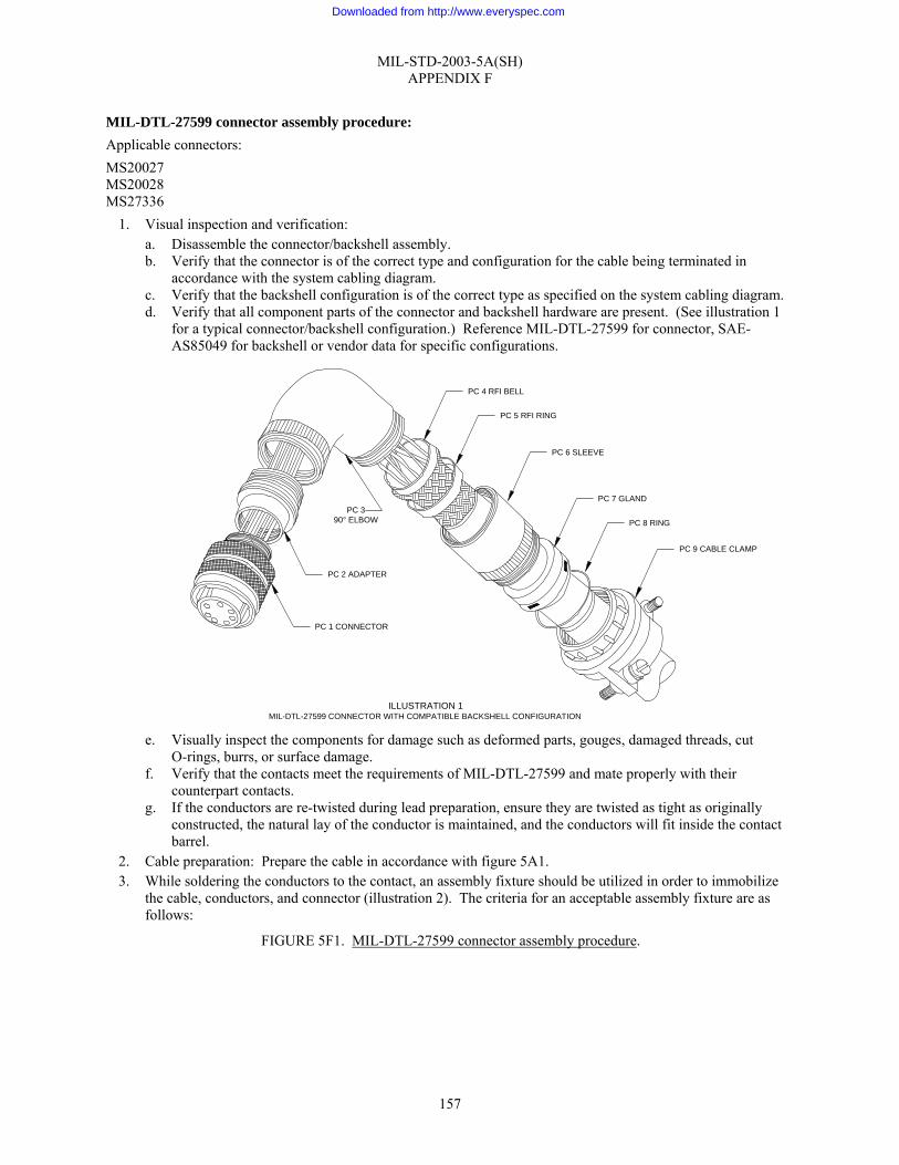
MIL-STD-2003-5A(SH) APPENDIX F
157
MIL-DTL-27599 connector assembly procedure: Applicable connectors: MS20027 MS20028 MS27336
1. Visual inspection and verification: a. Disassemble the connector/backshell assembly. b. Verify that the connector is of the correct type and configuration for the cable being terminated in
accordance with the system cabling diagram. c. Verify that the backshell configuration is of the correct type as specified on the system cabling diagram. d. Verify that all component parts of the connector and backshell hardware are present. (See illustration 1
for a typical connector/backshell configuration.) Reference MIL-DTL-27599 for connector, SAE-AS85049 for backshell or vendor data for specific configurations.
e. Visually inspect the components for damage such as deformed parts, gouges, damaged threads, cut
O-rings, burrs, or surface damage. f. Verify that the contacts meet the requirements of MIL-DTL-27599 and mate properly with their
counterpart contacts. g. If the conductors are re-twisted during lead preparation, ensure they are twisted as tight as originally
constructed, the natural lay of the conductor is maintained, and the conductors will fit inside the contact barrel.
2. Cable preparation: Prepare the cable in accordance with figure 5A1. 3. While soldering the conductors to the contact, an assembly fixture should be utilized in order to immobilize
the cable, conductors, and connector (illustration 2). The criteria for an acceptable assembly fixture are as follows:
FIGURE 5F1. MIL-DTL-27599 connector assembly procedure.
ILLUSTRATION 1MIL-DTL-27599 CONNECTOR WITH COMPATIBLE BACKSHELL CONFIGURATION
PC 1 CONNECTOR
PC 2 ADAPTER
PC 390° ELBOW
PC 4 RFI BELL
PC 5 RFI RING
PC 6 SLEEVE
PC 7 GLAND
PC 8 RING
PC 9 CABLE CLAMP
Downloaded from http://www.everyspec.com
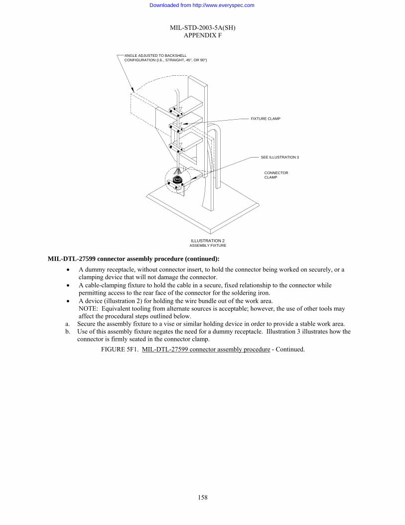
MIL-STD-2003-5A(SH) APPENDIX F
158
MIL-DTL-27599 connector assembly procedure (continued): • A dummy receptacle, without connector insert, to hold the connector being worked on securely, or a
clamping device that will not damage the connector. • A cable-clamping fixture to hold the cable in a secure, fixed relationship to the connector while
permitting access to the rear face of the connector for the soldering iron. • A device (illustration 2) for holding the wire bundle out of the work area.
NOTE: Equivalent tooling from alternate sources is acceptable; however, the use of other tools may affect the procedural steps outlined below.
a. Secure the assembly fixture to a vise or similar holding device in order to provide a stable work area. b. Use of this assembly fixture negates the need for a dummy receptacle. Illustration 3 illustrates how the
connector is firmly seated in the connector clamp. FIGURE 5F1. MIL-DTL-27599 connector assembly procedure - Continued.
FIXTURE CLAMP
ANGLE ADJUSTED TO BACKSHELLCONFIGURATION (I.E., STRAIGHT, 45°, OR 90°)
CONNECTORCLAMP
SEE ILLUSTRATION 3
ILLUSTRATION 2ASSEMBLY FIXTURE
Downloaded from http://www.everyspec.com
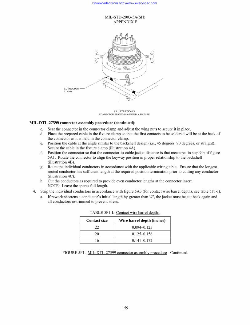
MIL-STD-2003-5A(SH) APPENDIX F
159
MIL-DTL-27599 connector assembly procedure (continued): c. Seat the connector in the connector clamp and adjust the wing nuts to secure it in place. d. Place the prepared cable in the fixture clamp so that the first contacts to be soldered will be at the back of
the connector as it is held in the connector clamp. e. Position the cable at the angle similar to the backshell design (i.e., 45 degrees, 90 degrees, or straight).
Secure the cable in the fixture clamp (illustration 4A). f. Position the connector so that the connector-to-cable jacket distance is that measured in step 9.b of figure
5A1. Rotate the connector to align the keyway position in proper relationship to the backshell (illustration 4B).
g. Route the individual conductors in accordance with the applicable wiring table. Ensure that the longest routed conductor has sufficient length at the required position termination prior to cutting any conductor (illustration 4C).
h. Cut the conductors as required to provide even conductor lengths at the connector insert. NOTE: Leave the spares full length.
4. Strip the individual conductors in accordance with figure 5A3 (for contact wire barrel depths, see table 5F1-I). a. If rework shortens a conductor’s initial length by greater than ¼", the jacket must be cut back again and
all conductors re-trimmed to prevent stress.
TABLE 5F1-I. Contact wire barrel depths.
Contact size Wire barrel depth (inches)
22 0.094–0.125 20 0.125–0.156 16 0.141–0.172
FIGURE 5F1. MIL-DTL-27599 connector assembly procedure - Continued.
ILLUSTRATION 3CONNECTOR SEATED IN ASSEMBLY FIXTURE
CONNECTORCLAMP
Downloaded from http://www.everyspec.com
MIL-STD-2003-5A(SH) APPENDIX F
160
MIL-DTL-27599 connector assembly procedure (continued): 5. Tin individual conductors in accordance with figure 5A5.
a. Ensure conductor strands are twisted tight prior to tinning. 6. Solder the conductors to the contacts in accordance with figure 5A6. Soldering should start with the contact
row(s) furthest away from the operator. A piece of stiff fire-retardant paper should be inserted between the rows as they are completed to aid in protecting the work already completed (see illustration 5 for example). WARNING: Do not move the conductor after the soldering iron has been removed or a cold solder joint could result.
7. Remove the cable and connector from the assembly fixture. 8. Conduct a visual check of the connector and verify wire location against the wiring table. Ensure no debris is
inside socket contacts. 9. Backshell assembly:
NOTE: This connector specification does not provide for unique connector accessory hardware to be utilized with the connectors. The following assembly procedure is based on the nomenclature and hardware configuration depicted in illustration 1. Variations in hardware design based on manufacturer may occur and cause minor deviations from this procedure. Assembly procedures supplied by the backshell manufacturers should be utilized when conflicts exist.
FIGURE 5F1. MIL-DTL-27599 connector assembly procedure - Continued.
Downloaded from http://www.everyspec.com
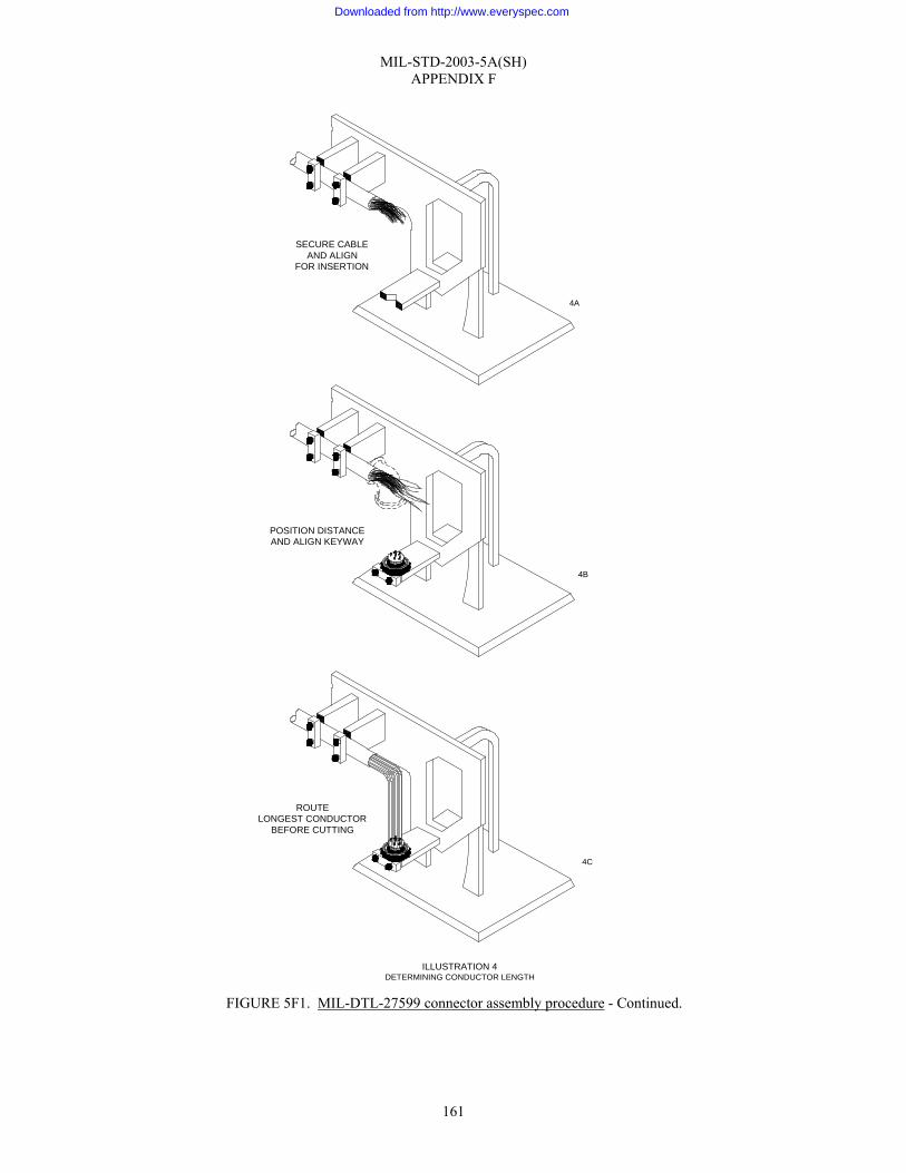
MIL-STD-2003-5A(SH) APPENDIX F
161
FIGURE 5F1. MIL-DTL-27599 connector assembly procedure - Continued.
4A
SECURE CABLEAND ALIGN
FOR INSERTION
4B
POSITION DISTANCEAND ALIGN KEYWAY
4C
ROUTELONGEST CONDUCTOR
BEFORE CUTTING
ILLUSTRATION 4DETERMINING CONDUCTOR LENGTH
Downloaded from http://www.everyspec.com

MIL-STD-2003-5A(SH) APPENDIX F
162
MIL-DTL-27599 connector assembly procedure (continued): a. Fold spare wires back one-half the distance between the connector and the jacket end. b. Slide a 1" long piece of appropriately sized shrink tubing over each folded pair and shrink in place.
c. Lightly coat the thread of each backshell part with petrolatum (AN-P-51 or equivalent) just prior to using. d. Position and lubricate (petrolatum, AN-P-51 or equivalent) all O-rings. e. Slide the backshell adapter (PC 2, illustration 1) down the cable and screw it onto the connector. Tighten
the adapter appropriately. f. Slide the 90-degree elbow (PC 3, illustration 1) down and screw it onto the adapter. Tighten the elbow
appropriately. g. If the gross shield is to be floated or terminated to a connector contact, proceed to step 9.h. If the shield
is to be terminated to the backshell RFI hardware, proceed as follows: (1) Slide the RFI bell (PC 4, illustration 1) against the elbow. (2) Flare the gross shield over the tapered end of the RFI bell. (3) Gently force the cable toward the connector plug until the shield covers the tapered surface on the
RFI bell. (4) Slide the RFI ring (PC 5, illustration 1) onto the RFI bell while applying forward pressure on the
cable. (5) Compress the shield between the RFI bell and RFI ring with a back and forth twisting forward
motion on the RFI ring. h. Slide the RFI backshell components (PC 4 & 5, illustration 1) over the pigtails, looped ground wire, and
spare conductors. i. Slide the sleeve (PC 6, illustration 1) over the RFI assembly and screw the sleeve onto the elbow. j. Tighten the sleeve appropriately. k. Mark a line on the cable ¼"-½" above the backshell sleeve (see illustration 6). Carefully push the cable
into the backshell ¼"-½" and maintain continuous pressure to hold at this position for the next four steps. (Line marked on jacket is parallel with backshell sleeve end.)
l. Verify the cable jacket is positioned completely through the gland. m. Slide the gland (PC 7, illustration 1) and ring (PC 8, illustration 1) into position behind the sleeve. n. Screw the cable clamp (PC 9, illustration 1) onto the sleeve and tighten appropriately.
FIGURE 5F1. MIL-DTL-27599 connector assembly procedure - Continued.
SOLDERED CONTACT
WORK IN PROGRESS
STIFF PAPER
ILLUSTRATION 5PROTECTING SOLDERED CONTACTS
Downloaded from http://www.everyspec.com
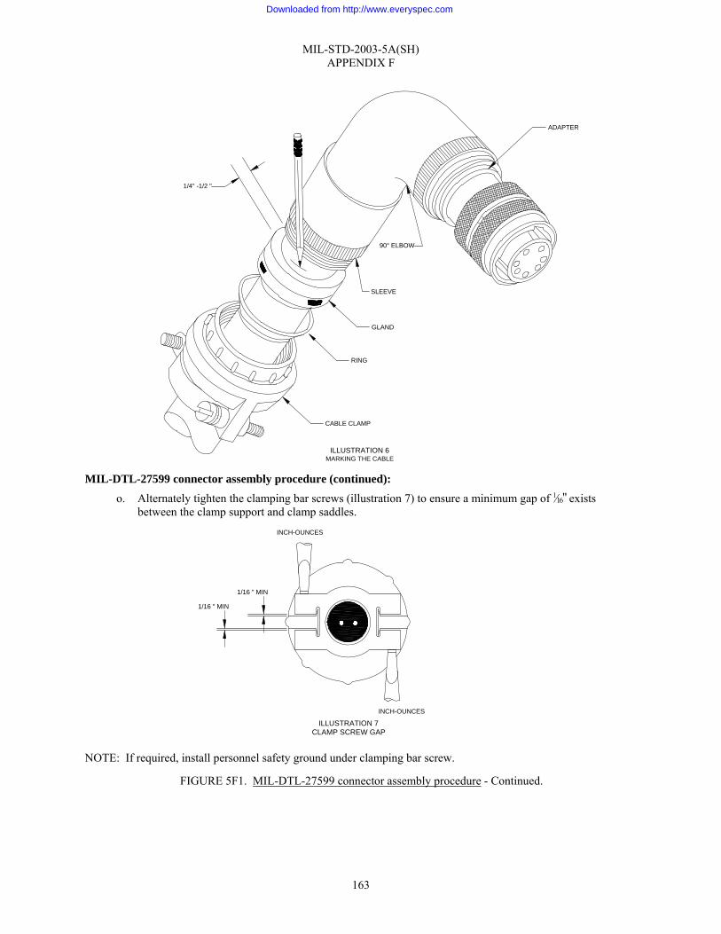
MIL-STD-2003-5A(SH) APPENDIX F
163
MIL-DTL-27599 connector assembly procedure (continued):
o. Alternately tighten the clamping bar screws (illustration 7) to ensure a minimum gap of 1⁄16" exists between the clamp support and clamp saddles.
NOTE: If required, install personnel safety ground under clamping bar screw.
FIGURE 5F1. MIL-DTL-27599 connector assembly procedure - Continued.
CABLE CLAMP
RING
GLAND
90° ELBOW
ADAPTER
1/4" -1/2 "
ILLUSTRATION 6MARKING THE CABLE
SLEEVE
ILLUSTRATION 7CLAMP SCREW GAP
1/16 " MIN
1/16 " MIN
INCH-OUNCES
INCH-OUNCES
Downloaded from http://www.everyspec.com

MIL-STD-2003-5A(SH) APPENDIX F
164
10. Final test and documentation: a. Using established shipyard procedures, perform electrical/electronic checks on the assembled connector. b. Install a protective dust cap on the connector. c. Complete the assembly inspection and documentation as required by local procedures.
11. If necessary, lockwire the connector in accordance with figure 5A9.
FIGURE 5F1. MIL-DTL-27599 connector assembly procedure - Continued.
Downloaded from http://www.everyspec.com

MIL-STD-2003-5A(SH) APPENDIX G
165
GROUP 5G - MIL-DTL-22992 CONNECTORS
G.1 SCOPE
G.1.1 Scope. This appendix provides instruction for preparing cable in preparation for MIL-DTL-22992 connectors and assembly of such connectors.
G.2 APPLICABLE DOCUMENTS
G.2.1 General. The documents listed in this section are specified in this appendix. This section does not include documents cited in other sections of this standard or recommended for additional information or as examples. While every effort has been made to ensure the completeness of this list, document users are cautioned that they must meet all specified requirements of documents cited in this appendix, whether or not they are listed.
G.2.2 Government documents.
G.2.2.1 Specifications, standards, and handbooks. The following specifications, standards, and handbooks form a part of this document to the extent specified herein. Unless otherwise specified, the issues of these documents are those cited in the solicitation or contract.
DEPARTMENT OF DEFENSE SPECIFICATIONS
MIL-DTL-22992 - Connectors, Plugs and Receptacles, Electrical, Waterproof, Quick Disconnect, Heavy Duty Type, General Specification for
DEPARTMENT OF DEFENSE STANDARDS
MS17344 - Connector, Plug, Electrical, Straight
MS17345 - Connector, Plug, Electrical, Cable Connecting, Female
(Copies of these documents are available online at http://assist.daps.dla.mil/quicksearch/ or from the Standardization Document Order Desk, 700 Robbins Avenue, Building 4D, Philadelphia, PA 19111-5094.)
G.2.2 Non-Government publications. The following documents form a part of this document to the extent specified herein. Unless otherwise specified, the issues of these documents are those cited in the solicitation or contract.
SAE INTERNATIONAL
SAE-AS85049 - Connector Accessories, Electrical General Specification For
(Copies of this document are available from SAE World Headquarters, 400 Commonwealth Drive, Warrendale, PA 15096-0001 or online at www.sae.org.)
G.2.4 Order of precedence. Unless otherwise noted herein or in the contract, in the event of a conflict between the text of this document and the references cited herein, the text of this document takes precedence. Nothing in this document, however, supersedes applicable laws and regulations unless a specific exemption has been obtained.
G.3 REQUIRED EQUIPMENT AND MATERIALS
G.3.1 Required equipment and materials. The required equipment and materials are specified in the standard methods of this section.
G.4 NOTES AND PROCEDURES
G.4.1 Dimensions. For figures and tables in this section, all dimensions are in inches unless otherwise noted.
G.4.2 Figures. Table 5GI provides information for the figures in this group.
Downloaded from http://www.everyspec.com

MIL-STD-2003-5A(SH) APPENDIX G
166
TABLE 5GI. Figures for MIL-DTL-22992 connector assembly procedures.
Figure Number MIL-DTL-22992 Connector Assembly Procedures Page
5G1 MIL-DTL-22992 connector assembly procedure 167
Downloaded from http://www.everyspec.com
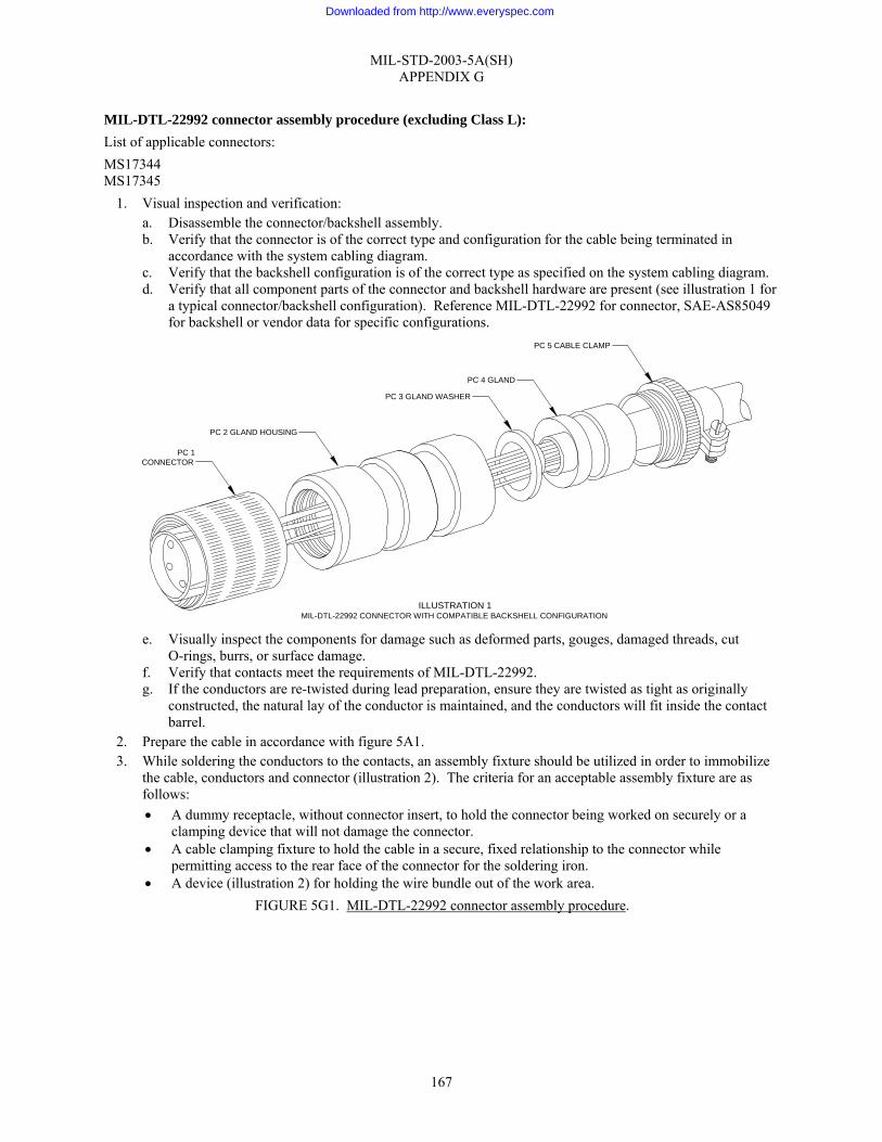
MIL-STD-2003-5A(SH) APPENDIX G
167
MIL-DTL-22992 connector assembly procedure (excluding Class L): List of applicable connectors: MS17344 MS17345
1. Visual inspection and verification: a. Disassemble the connector/backshell assembly. b. Verify that the connector is of the correct type and configuration for the cable being terminated in
accordance with the system cabling diagram. c. Verify that the backshell configuration is of the correct type as specified on the system cabling diagram. d. Verify that all component parts of the connector and backshell hardware are present (see illustration 1 for
a typical connector/backshell configuration). Reference MIL-DTL-22992 for connector, SAE-AS85049 for backshell or vendor data for specific configurations.
e. Visually inspect the components for damage such as deformed parts, gouges, damaged threads, cut
O-rings, burrs, or surface damage. f. Verify that contacts meet the requirements of MIL-DTL-22992. g. If the conductors are re-twisted during lead preparation, ensure they are twisted as tight as originally
constructed, the natural lay of the conductor is maintained, and the conductors will fit inside the contact barrel.
2. Prepare the cable in accordance with figure 5A1. 3. While soldering the conductors to the contacts, an assembly fixture should be utilized in order to immobilize
the cable, conductors and connector (illustration 2). The criteria for an acceptable assembly fixture are as follows: • A dummy receptacle, without connector insert, to hold the connector being worked on securely or a
clamping device that will not damage the connector. • A cable clamping fixture to hold the cable in a secure, fixed relationship to the connector while
permitting access to the rear face of the connector for the soldering iron. • A device (illustration 2) for holding the wire bundle out of the work area.
FIGURE 5G1. MIL-DTL-22992 connector assembly procedure.
PC 1CONNECTOR
PC 2 GLAND HOUSING
PC 3 GLAND WASHER
PC 4 GLAND
PC 5 CABLE CLAMP
ILLUSTRATION 1MIL-DTL-22992 CONNECTOR WITH COMPATIBLE BACKSHELL CONFIGURATION
Downloaded from http://www.everyspec.com

MIL-STD-2003-5A(SH) APPENDIX G
168
NOTE: Equivalent tooling from alternate sources is acceptable. However, the use of other tools may affect the procedural steps outlined below.
MIL-DTL-22992 connector assembly procedure (excluding Class L) (continued): a. Prepare the connector and cable for soldering as follows:
(1) Secure the assembly fixture to a vise or similar holding device. (2) Use of this assembly fixture negates the need for a dummy receptacle. Illustration 3 illustrates how
the connector is firmly seated in the connector clamp.
FIGURE 5G1. MIL-DTL-22992 connector assembly procedure - Continued.
FIXTURE CLAMP
ANGLE ADJUSTED TO BACKSHELLCONFIGURATION (I.E., STRAIGHT, 45°, OR 90°)
CONNECTOR CLAMP
SEE ILLUSTRATION 3
ILLUSTRATION 2ASSEMBLY FIXTURE
ILLUSTRATION 3CONNECTOR SEATED IN ASSEMBLY FIXTURE
CONNECTORCLAMP
Downloaded from http://www.everyspec.com

MIL-STD-2003-5A(SH) APPENDIX G
169
MIL-DTL-22992 connector assembly procedure (excluding Class L) (continued): (3) Seat the connector in the connector clamp and adjust the wing nuts to secure it in place. (4) Place the prepared cable in the fixture clamp so that the first contacts to be soldered will be at the
back of the connector as it is held in the connector clamp. (5) Position the cable at the angle similar to backshell design (i.e., 45 degrees, 90 degrees, or straight).
Secure the cable in the fixture clamp (illustration 4A). (6) Position the connector so that the connector-to-cable jacket distance is that measured in step 9.b of
figure 5A1. Rotate the connector to align the keyway position in proper relationship to the backshell (illustration 4B).
(7) Route the individual conductors in accordance with the applicable wiring table. Ensure that the longest routed conductor has sufficient length at the required position termination prior to cutting any conductor (illustration 4C).
b. Cut the conductors as required to provide even conductor lengths at the connector insert.
NOTE: Leave the spare leads full length.
TABLE 5G1-I. Contact wire barrel depths.
Contact barrel size Wire barrel depth (inches)
16 0.250–0.313 12 0.375–0.438 8 0.500–0.563 4 0.625–0.688 0 0.625–0.688
FIGURE 5G1. MIL-DTL-22992 connector assembly procedure - Continued.
4CROUTE
LONGEST CONDUCTOR BEFORE CUTTING
D
4A SECURE CABLEAND ALIGN FOR
INSERTION
4BPOSITION AT
DISTANCE AND ALIGN KEYWAY
ILLUSTRATION 4DETERMINING CONDUCTOR LENGTH
Downloaded from http://www.everyspec.com

MIL-STD-2003-5A(SH) APPENDIX G
170
MIL-DTL-22992 connector assembly procedure (excluding Class L) (continued): 4. Strip the individual conductors in accordance with figure 5A3 (for contact wire barrel depths, see table 5G1-
I). 5. Tin the conductors in accordance with figure 5A5.
a. Ensure conductor strands are twisted tight prior to tinning. b. If rework shortens a conductor’s initial length by greater than ¼", the jacket must be cut back again and
all leads re-trimmed to preclude stress. 6. Solder the conductors to the contacts in accordance with figure 5A6. Soldering should start with the contact
row(s) furthest away from the operator. A piece of stiff fire-retardant paper should be inserted between the rows as they are completed to aid in protecting the work already accomplished (see illustration 5 for example).
WARNING: Do not move the conductor after the soldering iron has been removed or a cold solder joint could result.
7. Remove the connector and cable from the assembly fixture. 8. Conduct a visual check of the connector and verify wire location against the wiring table. Ensure no debris is
inside socket contacts. 9. Backshell assembly:
NOTE: The following assembly procedure is based on the nomenclature and hardware configuration depicted in illustration 1. Variations in hardware design based on manufacturer may occur and cause minor deviations from this procedure. The applicable manufacturer’s instructions should be utilized to resolve assembly procedure conflicts for configurations not covered in this procedure. a. Lubricate the threads of all backshell components with petrolatum (AN-P-51 or equivalent) prior to
assembly. b. Fold spare wires back one-half the distance between the connector and the jacket end. c. Slide a 1" long piece of appropriately sized shrink tubing over each folded pair and shrink in place. d. Position and lubricate all O-rings. e. Slide the gland housing (PC 2, illustration 1) down the cable and screw it onto the connector. Tighten the
gland housing appropriately. FIGURE 5G1. MIL-DTL-22992 connector assembly procedure - Continued.
COMPLETED WORK
WORK IN PROGRESS
ILLUSTRATION 5PROTECTING SOLDERED CONTACTS
STIFF PAPER
Downloaded from http://www.everyspec.com

MIL-STD-2003-5A(SH) APPENDIX G
171
MIL-DTL-22992 connector assembly procedure (excluding Class L) (continued): f. Slide the gland washer (PC 3, illustration 1) and gland (PC 4, illustration 1) into the gland housing.
Ensure the cable jacket extends through the area under the gland. g. Screw the cable clamp (PC 5, illustration 1) into the gland housing and tighten appropriately. h. Alternately tighten the clamping bar screws(illustration 6) to ensure a minimum gap of 1⁄16" exists between
the clamp support and clamp saddles. NOTE: If required, install personnel safety ground under clamping bar screw.
10. Final test and documentation:
a. Using established shipyard procedures, perform electrical/electronic checks on the assembled connector. b. Install a protective dust cap on the connector. c. Complete the assembly inspection and documentation as required by local procedures.
11. If necessary, lockwire the connector in accordance with figure 5A9.
FIGURE 5G1. MIL-DTL-22992 connector assembly procedure - Continued.
1/16 " MIN
1/16 " MIN
INCH-OUNCES
INCH-OUNCES
ILLUSTRATION 6
Downloaded from http://www.everyspec.com
MIL-STD-2003-5A(SH) APPENDIX H
172
GROUP 5H - MIL-DTL-38999 CONNECTORS
H.1 SCOPE
H.1.1 Scope. This appendix provides instructions for preparing cable in preparation for MIL-DTL-38999 connectors and assembly of such connectors.
H.2 APPLICABLE DOCUMENTS
H.2.1 General. The documents listed in this section are specified in this appendix. This section does not include documents cited in other sections of this standard or recommended for additional information or as examples. While every effort has been made to ensure the completeness of this list, document users are cautioned that they must meet all specified requirements of documents cited in this appendix, whether or not they are listed.
H.2.2 Government documents.
H.2.2.1 Specifications, standards, and handbooks. The following specifications, standards, and handbooks form a part of this document to the extent specified herein. Unless otherwise specified, the issues of these documents are those cited in the solicitation or contract.
DEPARTMENT OF DEFENSE SPECIFICATIONS
MIL-DTL-28840 - Connectors, Electrical, Circular, Threaded, High Density, High Shock, Shipboard, Class D, General Specification for
MIL-DTL-38999 - Connectors, Electrical Circular, Miniature, High Density, Quick Disconnect (Bayonet, Threaded and Breech Coupling), Environment Resistant, Removable Crimp and Hermetic Solder Contacts, General Specification for
DEPARTMENT OF DEFENSE STANDARDS
MS27467 - Connectors, Plug, Electrical, Straight, Crimp Type, Bayonet Coupling, Series I
MS27468 - Connector, Receptacle, Electrical Jam Nut Mounting, Crimp Type, Bayonet Coupling, Series I
MS27473 - Connectors, Plug, Electrical, Straight, Crimp Type, Bayonet Coupling, Series II
MS27484 - Connectors, Plug, Electrical, Straight, Crimp Type, Bayonet Coupling, EMI, Series II
MS27488 - Plug, End Seal, Electrical Connector
MS27500 - Connectors, Plug, Electrical, 90 Degrees Elbow, crimp Type, Bayonet Coupling, Series II
MS27653 - Connectors, Plug, Electrical, Straight, Crimp Type, Bayonet Coupling, Series I
MS27661 - Connectors, Plug, Electrical, Crimp Type, Lanyard Release, Fail-Safe, Series I
(Copies of these documents are available online at http://assist.daps.dla.mil/quicksearch/ or from the Standardization Document Order Desk, 700 Robbins Avenue, Building 4D, Philadelphia, PA 19111-5094.)
Downloaded from http://www.everyspec.com

MIL-STD-2003-5A(SH) APPENDIX H
173
H.2.2 Non-Government publications. The following documents form a part of this document to the extent specified herein. Unless otherwise specified, the issues of these documents are those cited in the solicitation or contract.
SAE INTERNATIONAL
SAE-AS31971 - Gage Pin for Socket Contact Engagement Test
SAE-AS39029/56 - Contacts, Electrical Connector, Socket, Crimp Removable (for MIL-C-38999 Series I, III, and IV Connectors)
SAE-AS39029/57 - Contacts, Electrical Connectors, Socket Crimp Removable (for MIL-C-24308, MIL-C-38999 Series II, MIL-C-55302/68, /71, /72, /75 and MIL-C-83733 Connectors)
SAE-AS39029/58 - Contacts, Electrical Connector, Pin, Crimp Removable (for MIL-C-24308, MIL-C-38999 Series I, II, III, and IV, and MIL-C-55302/69 and MIL-C- 83733 Connectors)
SAE-AS85049 - Connector Accessories, Electrical General Specification For
(Copies of these documents are available from SAE World Headquarters, 400 Commonwealth Drive, Warrendale, PA 15096-0001 or online at www.sae.org.)
H.2.4 Order of precedence. Unless otherwise noted herein or in the contract, in the event of a conflict between the text of this document and the references cited herein, the text of this document takes precedence. Nothing in this document, however, supersedes applicable laws and regulations unless a specific exemption has been obtained.
H.3 REQUIRED EQUIPMENT AND MATERIALS
H.3.1 Required equipment and materials. The required equipment and materials are specified in the standard methods of this section.
H.4 NOTES AND PROCEDURES
H.4.1 Dimensions. For figures and tables in this section, all dimensions are in inches unless otherwise noted.
H.4.2 Figures. Table 5HI provides information for the figures in this group.
TABLE 5HI. Figures for MIL-DTL-38999 connector assembly procedures.
Figure Number MIL-DTL-38999 Connector Assembly Procedures Page
5H1 MIL-DTL-38999 connector assembly procedure 174
Downloaded from http://www.everyspec.com
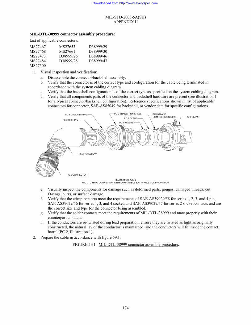
MIL-STD-2003-5A(SH) APPENDIX H
174
MIL-DTL-38999 connector assembly procedure: List of applicable connectors: MS27467 MS27653 D38999/29 MS27468 MS27661 D38999/30 MS27473 D38999/26 D38999/46 MS27484 D38999/28 D38999/47 MS27500
1. Visual inspection and verification: a. Disassemble the connector/backshell assembly. b. Verify that the connector is of the correct type and configuration for the cable being terminated in
accordance with the system cabling diagram. c. Verify that the backshell configuration is of the correct type as specified on the system cabling diagram. d. Verify that all components parts of the connector and backshell hardware are present (see illustration 1
for a typical connector/backshell configuration). Reference specifications shown in list of applicable connectors for connector, SAE-AS85049 for backshell, or vendor data for specific configurations.
e. Visually inspect the components for damage such as deformed parts, gouges, damaged threads, cut
O-rings, burrs, or surface damage. f. Verify that the crimp contacts meet the requirements of SAE-AS39029/58 for series 1, 2, 3, and 4 pin,
SAE-AS39029/56 for series 1, 3, and 4 socket, and SAE-AS39029/57 for series 2 socket contacts and are the correct size and type for the connector being assembled.
g. Verify that the solder contacts meet the requirements of MIL-DTL-38999 and mate properly with their counterpart contacts.
h. If the conductors are re-twisted during lead preparation, ensure they are twisted as tight as originally constructed, the natural lay of the conductor is maintained, and the conductors will fit inside the contact barrel (PC 2, illustration 1).
2. Prepare the cable in accordance with figure 5A1.
FIGURE 5H1. MIL-DTL-38999 connector assembly procedure.
PC 1 CONNECTOR
PC 2 45° ELBOW
PC 3 RFI RING
PC 4 GROUND RING PC 5 TRANSITION SHELL
PC 6 WASHER
PC 7 GLAND
PC 8 GLANDCOMPRESSION RING PC 9 CLAMP
ILLUSTRATION 1MIL-DTL-38999 CONNECTOR WITH COMPATIBLE BACKSHELL CONFIGURATION
Downloaded from http://www.everyspec.com

MIL-STD-2003-5A(SH) APPENDIX H
175
MIL-DTL-38999 connector assembly procedure (continued): 3. Insertion setup: Owing to the many possible variations for acceptable tooling for contact insertion and
soldering, no specification is made as to a particular type. The criteria, which are desirable for an acceptable assembly fixture, are as follows: • A dummy receptacle, without connector insert, to hold the connector being worked on securely or a
clamping device that will not damage the connector. • A cable clamping fixture to hold the cable in a secure, fixed relationship to the connector while
permitting access to the rear face of the connector for the contact insertion tool or soldering iron. • A device (illustration 2) for holding the wire bundle out of the work area.
NOTE: Equivalent tooling from alternate sources is acceptable. However, the use of other tools may affect the procedural steps outlined below. a. Secure the assembly fixture to a vise or similar holding device in order to provide a stable work area. b. Use of this assembly fixture negates the need for a dummy receptacle. Illustration 3 illustrates how the
connector is firmly seated in the connector clamp. FIGURE 5H1. MIL-DTL-38999 connector assembly procedure - Continued.
ILLUSTRATION 2ASSEMBLY FIXTURE
FIXTURE CLAMP
ANGLE ADJUSTED TO BACKSHELLCONFIGURATION (I.E., STRAIGHT, 45°, OR 90°)
CONNECTORCLAMP
SEE ILLUSTRATION 3
Downloaded from http://www.everyspec.com
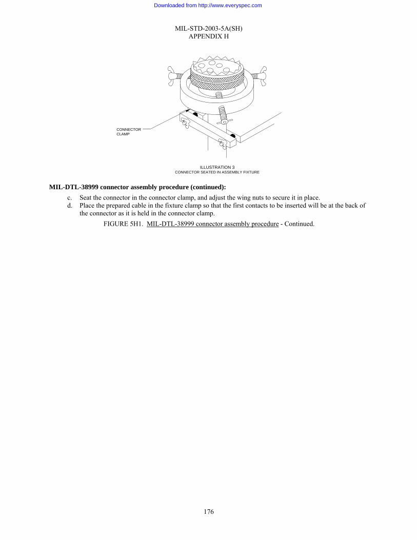
MIL-STD-2003-5A(SH) APPENDIX H
176
MIL-DTL-38999 connector assembly procedure (continued): c. Seat the connector in the connector clamp, and adjust the wing nuts to secure it in place. d. Place the prepared cable in the fixture clamp so that the first contacts to be inserted will be at the back of
the connector as it is held in the connector clamp. FIGURE 5H1. MIL-DTL-38999 connector assembly procedure - Continued.
ILLUSTRATION 3CONNECTOR SEATED IN ASSEMBLY FIXTURE
CONNECTORCLAMP
Downloaded from http://www.everyspec.com

MIL-STD-2003-5A(SH) APPENDIX H
177
FIGURE 5H1. MIL-DTL-38999 connector assembly procedure - Continued.
SECURE CABLEAND ALIGNFOR INSERTION
ILLUSTRATION 4DETERMINING CONDUCTOR LENGTH
POSITION DISTANCEAND ALIGNKEYWAY
ROUTE LONGESTCONDUCTOR BEFORE
CUTTING
4A
4B
4C
Downloaded from http://www.everyspec.com

MIL-STD-2003-5A(SH) APPENDIX H
178
MIL-DTL-38999 connector assembly procedure (continued): e. Position the cable at the angle similar to backshell design (i.e., 45 degrees, 90 degrees, or straight).
Secure the cable in the fixture clamp (illustration 4A). f. Position the connector so that the connector-to-cable jacket distance is that measured in step 9.b of figure
5A1. Rotate the connector to align the keyway position in proper relationship to the backshell (illustration 4B).
g. Route the individual conductors in accordance with the applicable wiring table. Ensure that the longest routed conductor has sufficient length at the required position termination prior to cutting any conductor (illustration 4C).
h. Cut the conductors as required to provide even conductor lengths at the connector insert. NOTE: Leave the spare leads full length.
4. Strip the individual conductors in accordance with figure 5A3 (for contact wire barrel depths, see table 5H1-I).
TABLE 5H1-I. Contact wire barrel depths.
Wire barrel depth (inches) Contact barrel size
Front release Rear release
12-12 0.209–0.229 0.141–0.172 16-16 0.209–0.229 0.141–0.172 20-20 0.209–0.229 0.125–0.156 22-22 0.141–0.157 0.094–0.125
22-22M 0.141–0.157 0.094–0.125 22-22D 0.141–0.157 0.094–0.125
NOTE: For solder contacts, proceed to step 6.
5. Crimp contact termination to connector: a. Prior to crimping, a contact-sizing test should be accomplished for all socket contacts (pin contacts
previously verified in step 1.f do not need further testing). (1) Socket contacts should be inspected for proper size using a pin contact gauge conforming to
SAE-AS31971. FIGURE 5H1. MIL-DTL-38999 connector assembly procedure - Continued.
Downloaded from http://www.everyspec.com

MIL-STD-2003-5A(SH) APPENDIX H
179
TABLE 5H1-II. Crimp tool guide.
Series 1, 2, 3 4 pin contact Series 1, 2, 3, 4 socket contact Contact size Basic crimping
tool Positioner Basic crimping tool Positioner
Minimum separation
force (ounces)
12-12 M22520/1-01 M22520/1-04 yellow
M22520/1-01 M22520/1-04 yellow
2.5
M22520/1-01 M22520/1-04 blue
M22520/1-01 M22520/1-04 blue
16-16
M22520/7-01 M22520/7-04 M22520/7-01 M22520/7-04
1.5
M22520/1-01 M22520/1-04 red
M22520/1-01 M22520/1-04 red
M22520/2-01 M22520/2-10 M22520/2-01 M22520/2-10
20-20
M22520/7-01 M22520/7-08 M22520/7-01 M22520/7-08
0.6
M22520/2-07 M22520/2-01 M22520/2-09 M22520/2-01
M22520/2-06*
M22520/7-05
22-22 22-22M 22-22D
M22520/7-01 M22520/7-07 M22520/7-01 M22520/7-06*
0.6
* Series 2 socket contacts only. MIL-DTL-38999 connector assembly procedure (continued):
b. Terminate individual conductors with crimp contacts in accordance with figure 5A4. See table 5H1-II for proper crimping tool. If contact rework shortens a conductor’s initial length by greater than ¼", the jacket must be cut back again and all conductors re-trimmed to avoid stress.
c. Inserting contacts (illustration 5). FIGURE 5H1. MIL-DTL-38999 connector assembly procedure - Continued.
Downloaded from http://www.everyspec.com

MIL-STD-2003-5A(SH) APPENDIX H
180
MIL-DTL-38999 connector assembly procedure (continued): (1) Using the proper wiring table, proper insertion tool based on contact type (see table 5H1-III), and
working from the rear to the front of the assembly fixture, insert the contacts into their designated locations in the connector as follows:
TABLE 5H1-III. Installation and removal tools.
Contact size Installing tool Removal tool
M81969/8-09 M81969/8-10 12-12 M81969/14-04 M81969/14-04 M81969/8-07 M81969/8-08 16-16 M81969/14-03 M81969/14-03 M81969/8-05 M81969/8-06 20-20 M81969/14-02 M81969/14-02
22-22 M81969/8-03 M81969/8-04 M81969/8-01 M81969/8-02 22-22M M81969/14-01 M81969/14-01 M81969/8-01 M81969/8-02 22-22D M81969/14-01 M81969/14-01
FIGURE 5H1. MIL-DTL-38999 connector assembly procedure - Continued.
SEAT CONTACT WITHINSERTION TOOL
POSITION INSERTION TOOLON CONTACT SHOULDER
ILLUSTRATION 5CONTACT INSERTION
Downloaded from http://www.everyspec.com
MIL-STD-2003-5A(SH) APPENDIX H
181
MIL-DTL-38999 connector assembly procedure (continued): (a) Position the contact in the tool. The tool tip should be against the contact shoulder just forward
of the wire barrel. (b) Insert the contact and tool tip into the contact cavity with a firm steady pressure. (c) Slide the insertion tool back along the wire until it clears the connector insert.
1 Lightly pull on the inserted lead to ensure the contact is locked in the connector. (d) Adjust the fixture clamp as required during the insertion process to ease stress on the conductors. (e) Ensure that the shield ground wire (if terminated to a contact) is inserted in its proper location. (f) Upon insertion of each two rows of pin contacts, visually inspect the connector face to ensure
that the contacts are properly inserted and do not “cross over” into adjacent pin holes. Any improperly inserted contacts will appear angled when compared to the properly inserted contacts.
(g) Insert sealing plugs meeting the requirements of MS27488 into all unwired contact holes. d. Remove the connector and cable from the assembly fixture. e. Conduct a visual check of the connector and verify wire location against the wiring table. Ensure no
debris is inside socket contacts. f. Contact removal procedure (as required).
(1) Conduct a visual check of the connector face to identify any unseated contacts. (2) If required to remove contacts, proceed as follows (illustration 6):
(a) Select the correct removal tool from table 5H1-III. (b) Straddle the wire of the contact to be removed with the removal tool. (c) Slide the tool into the insert until bottomed around the contact.
CAUTION: Do not twist the extractor tool. (d) Remove the contact and tool slowly from the connector. (e) Examine the connector and contact for damage. (f) Reinsert all extracted contacts and repeat the seating checks.
FIGURE 5H1. MIL-DTL-38999 connector assembly procedure - Continued.
Downloaded from http://www.everyspec.com

MIL-STD-2003-5A(SH) APPENDIX H
182
MIL-DTL-38999 connector assembly procedure (continued): (3) If a contact fails to reseat after three insertion attempts, replace the offending contact. If the same
contact location continues to give difficulty, the connector is probably damaged or faulty and must be replaced.
6. Solder termination to connector: a. Tin the conductors in accordance with figure 5A5.
(1) Ensure conductor strands are twisted tight prior to tinning. (2) If rework shortens a conductor’s initial length by greater than ¼", the jacket must be cut back again
and all leads re-trimmed to preclude stress. b. Solder the conductors to the contacts in accordance with figure 5A6. Soldering should start with the
contact row(s) furthest away from the operator. A piece of stiff fire-retardant paper should be inserted between the rows as they are completed to aid in protecting the work already accomplished (see illustration 8 for example).
FIGURE 5H1. MIL-DTL-38999 connector assembly procedure - Continued.
B. REMOVING THETOOL AND CONTACT
A. INSERTING THE TOOL INTOTHE CONNECTOR
ILLUSTRATION 6CONTACT REMOVAL (REAR RELEASE)
Downloaded from http://www.everyspec.com

MIL-STD-2003-5A(SH) APPENDIX H
183
MIL-DTL-38999 connector assembly procedure (continued): WARNING: Do not move the conductor after the soldering iron has been removed or a cold solder joint could result. c. Remove the cable and connector from the assembly fixture. d. Conduct a visual check of the connector and verify wire location against the wiring table. Ensure no
debris is inside socket contacts. 7. Backshell assembly:
NOTE: This connector specification does not provide for unique connector accessory hardware to be utilized with the connectors. The following assembly procedure is based on the nomenclature and hardware configuration depicted in illustration 1. Variations in hardware design based on manufacturer may occur and cause minor deviations from this procedure. Assembly procedures supplied by the backshell manufacturers should be utilized when conflicts exist. a. Fold spare wires back one-half the distance between the connector and the jacket end. b. Slide a 1" long piece of appropriately sized shrink tubing over each folded pair and shrink in place. c. Lightly coat the threads of each backshell part with petrolatum (AN-P-51 or equivalent) just prior to
assembly. d. Position and lubricate (petrolatum, AN-P-51 or equivalent) all O-rings. e. Slide the 45-degree elbow (PC 2, illustration 1) down the cable and screw it onto the connector. Tighten
the 45-degree elbow appropriately. FIGURE 5H1. MIL-DTL-38999 connector assembly procedure - Continued.
ILLUSTRATION 7PROTECTING SOLDERING CONTACTS
STIFF PAPER
WORK IN PROGRESS
COMPLETED WORK
Downloaded from http://www.everyspec.com
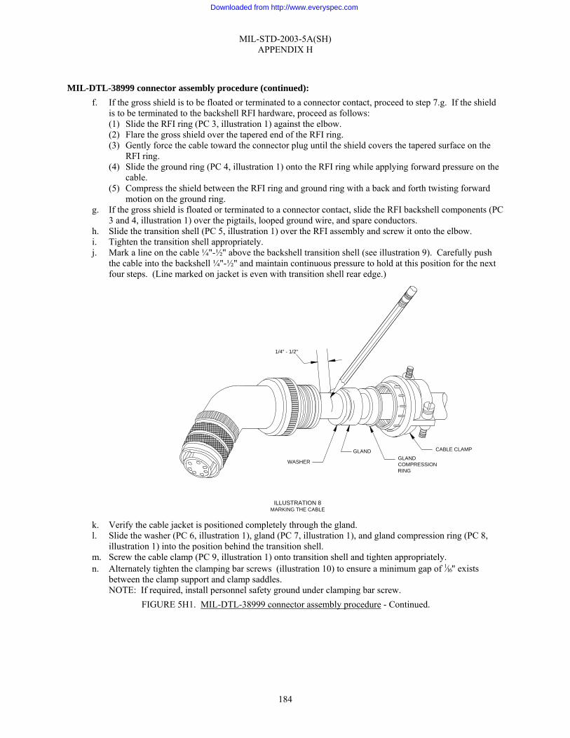
MIL-STD-2003-5A(SH) APPENDIX H
184
MIL-DTL-38999 connector assembly procedure (continued):
f. If the gross shield is to be floated or terminated to a connector contact, proceed to step 7.g. If the shield is to be terminated to the backshell RFI hardware, proceed as follows: (1) Slide the RFI ring (PC 3, illustration 1) against the elbow. (2) Flare the gross shield over the tapered end of the RFI ring. (3) Gently force the cable toward the connector plug until the shield covers the tapered surface on the
RFI ring. (4) Slide the ground ring (PC 4, illustration 1) onto the RFI ring while applying forward pressure on the
cable. (5) Compress the shield between the RFI ring and ground ring with a back and forth twisting forward
motion on the ground ring. g. If the gross shield is floated or terminated to a connector contact, slide the RFI backshell components (PC
3 and 4, illustration 1) over the pigtails, looped ground wire, and spare conductors. h. Slide the transition shell (PC 5, illustration 1) over the RFI assembly and screw it onto the elbow. i. Tighten the transition shell appropriately. j. Mark a line on the cable ¼"-½" above the backshell transition shell (see illustration 9). Carefully push
the cable into the backshell ¼"-½" and maintain continuous pressure to hold at this position for the next four steps. (Line marked on jacket is even with transition shell rear edge.)
k. Verify the cable jacket is positioned completely through the gland. l. Slide the washer (PC 6, illustration 1), gland (PC 7, illustration 1), and gland compression ring (PC 8,
illustration 1) into the position behind the transition shell. m. Screw the cable clamp (PC 9, illustration 1) onto transition shell and tighten appropriately. n. Alternately tighten the clamping bar screws (illustration 10) to ensure a minimum gap of 1⁄16" exists
between the clamp support and clamp saddles. NOTE: If required, install personnel safety ground under clamping bar screw.
FIGURE 5H1. MIL-DTL-38999 connector assembly procedure - Continued.
CABLE CLAMP
ILLUSTRATION 8MARKING THE CABLE
GLANDCOMPRESSIONRING
GLAND
WASHER
1/4" - 1/2"
Downloaded from http://www.everyspec.com

MIL-STD-2003-5A(SH) APPENDIX H
185
MIL-DTL-38999 connector assembly procedure (continued): 8. Final test and documentation:
a. Using established shipyard procedures, perform electrical/electronic checks on the assembled connector. b. Install a protective dust cap on the connector. c. Complete the assembly inspection and documentation as required by local procedures.
9. If necessary, lockwire the connector in accordance with figure 5A9.
FIGURE 5H1. MIL-DTL-38999 connector assembly procedure - Continued.
ILLUSTRATION 9CLAMPING BAR ADJUSTMENT
1/16 " MIN
1/16 " MIN
INCH-OUNCES
INCH-OUNCES
Downloaded from http://www.everyspec.com

MIL-STD-2003-5A(SH)
186
Preparing activity:
Navy – SH (Project SESS-2008-005)
NOTE: The activities listed above were interested in this document as of the date of this document. Since organizations and responsibilities can change, you should verify the currency of the information above using the ASSIST Online database at http://assist.daps.dla.mil.
Downloaded from http://www.everyspec.com