demosat iv critical design review metropolitan state college of denver april 21, 2006
TRANSCRIPT
DemoSat IV
Critical Design Review
Metropolitan State College of Denver
April 21, 2006

Three missions in two payloads
FieldSat and SolarSat will be in one payload. VideoSat will be in another.

Project Organization
Evan Spitler
Jason Helms Sarah Ryan
Devlin Thyne
Jason IgoTeam Captain
David Fifield
Matt Hanley
Video Sat Field Sat Solar Sat
Professor Keith NorwoodFaculty Advisor

Field/SolarSat System Requirements
The payload module must weigh less than 1.5kg
Record orientation and vibration data and store it on large-capacity media using Inertial Measurement Unit (IMU)
Deploy a solar panel and measure its efficiency before and after impact
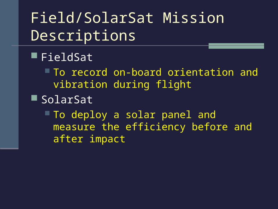
Field/SolarSat Mission Descriptions
FieldSat To record on-board orientation and vibration
during flight SolarSat
To deploy a solar panel and measure the efficiency before and after impact
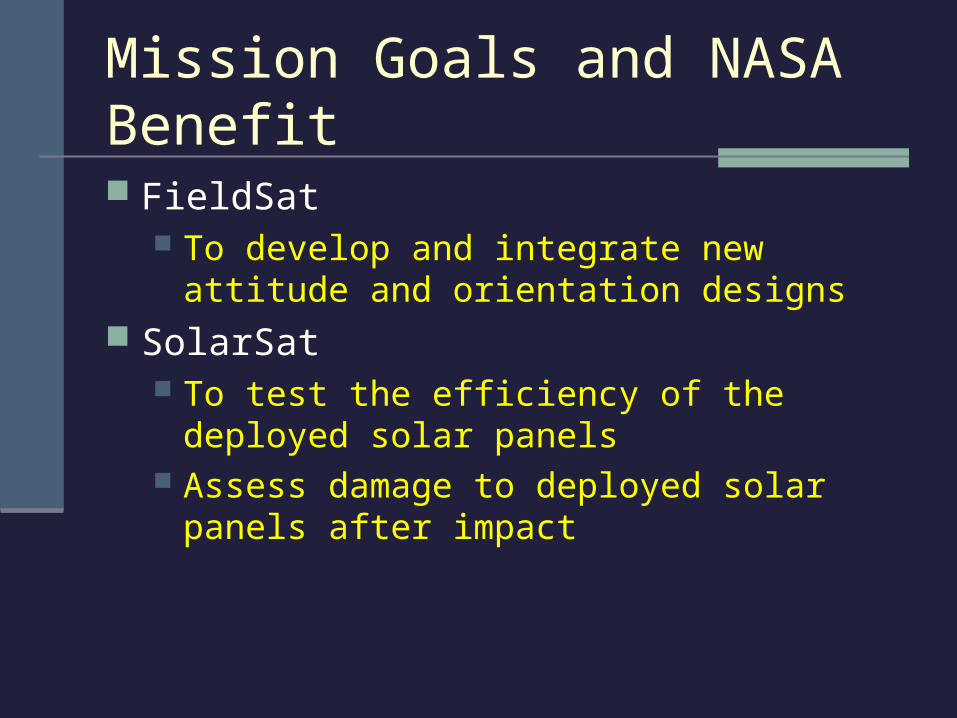
Mission Goals and NASA Benefit
FieldSat To develop and integrate new attitude and
orientation designs SolarSat
To test the efficiency of the deployed solar panels
Assess damage to deployed solar panels after impact
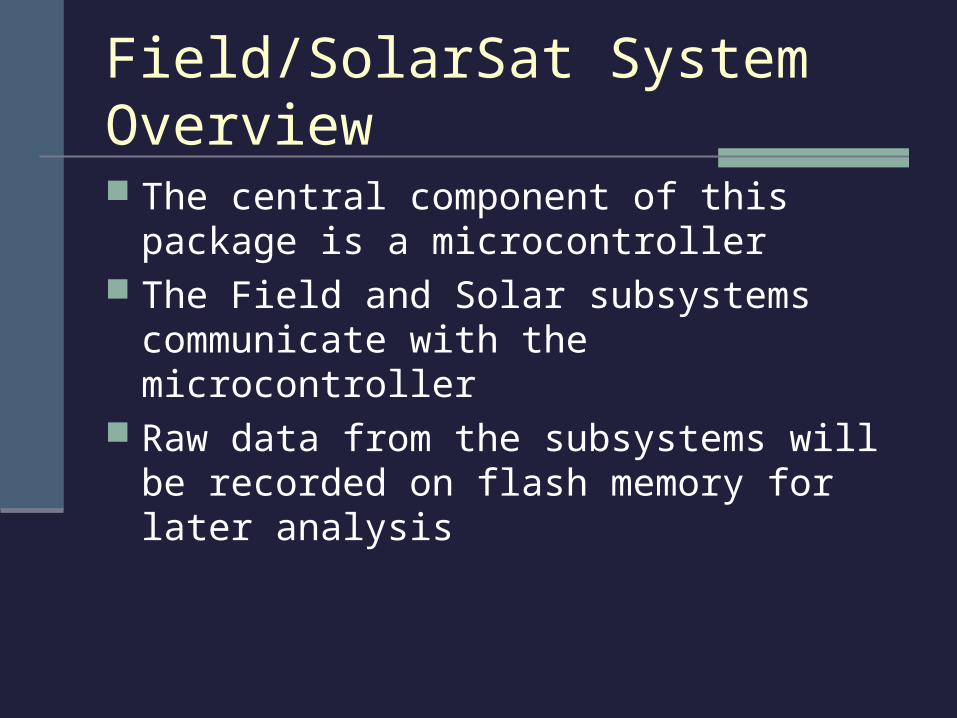
Field/SolarSat System Overview
The central component of this package is a microcontroller
The Field and Solar subsystems communicate with the microcontroller
Raw data from the subsystems will be recorded on flash memory for later analysis

Field/SolarSat System Interfaces
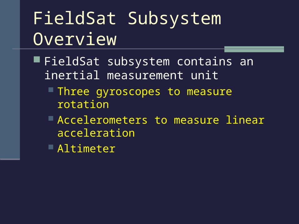
FieldSat Subsystem Overview
FieldSat subsystem contains an inertial measurement unit Three gyroscopes to measure rotation Accelerometers to measure linear acceleration Altimeter

FieldSat Subsystem Schematic
IMU
Accelerometers Gyroscopes Altimeter Microcontroller

FieldSat Subsystem Interface
Inputs: Kinematic motion
Outputs: Altitude Acceleration in three dimensions Rotation of three axes

SolarSat Subsystem Overview
SolarSat subsystem contains the solar cells, deployment latch, and solar measurement unit (SMU)
Solar cells will be thin-film variety and will collect a broad range of light wavelengths
SMU measures lumens, voltage and current Deployment latch will be a solenoid
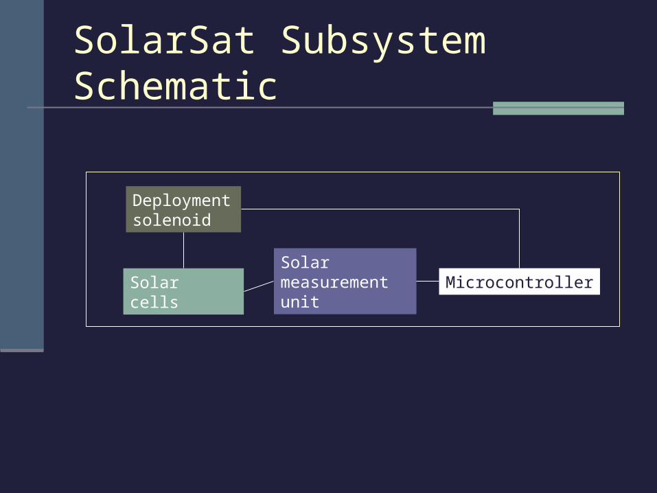
SolarSat Subsystem Schematic
Solar cells
Deployment solenoid
Solar measurement unit
Microcontroller
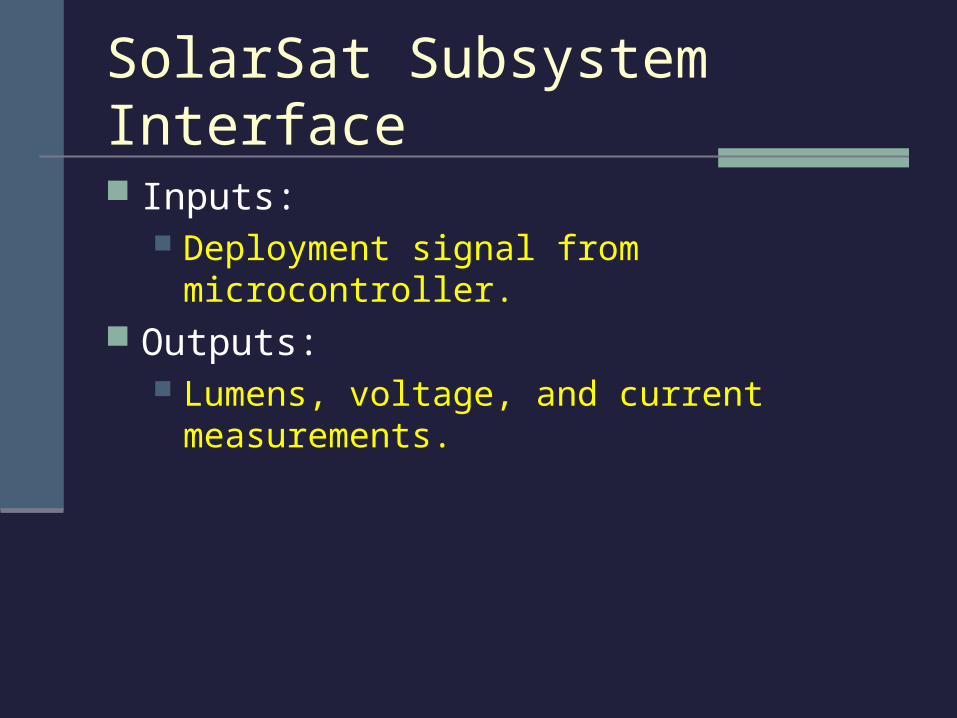
SolarSat Subsystem Interface
Inputs: Deployment signal from microcontroller.
Outputs: Lumens, voltage, and current measurements.
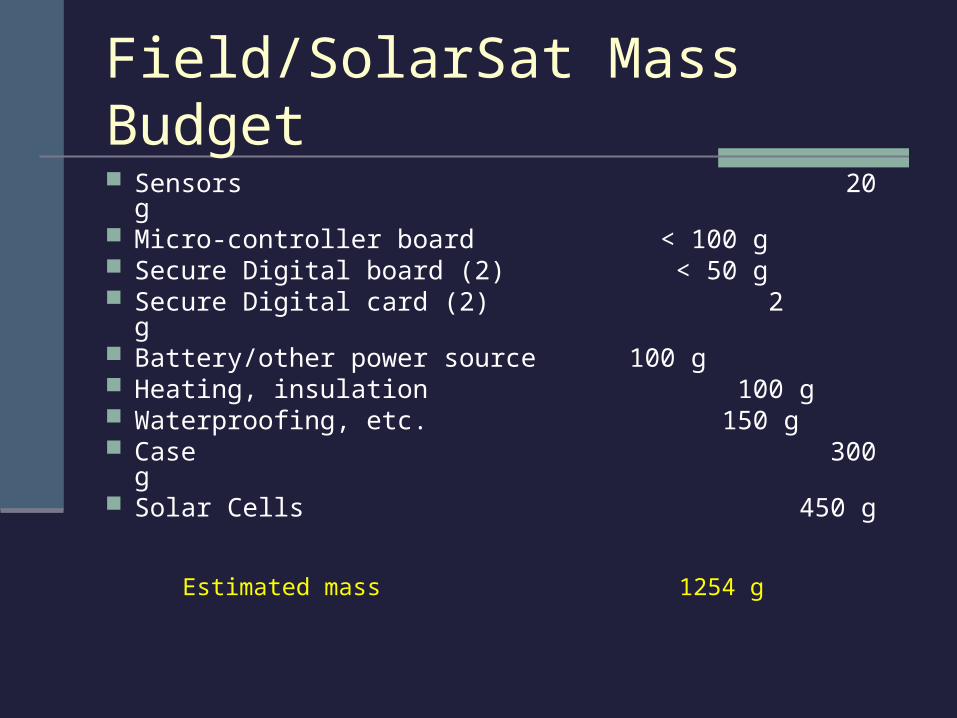
Field/SolarSat Mass Budget
Sensors 20 g Micro-controller board < 100 g Secure Digital board (2) < 50 g Secure Digital card (2) 2 g Battery/other power source 100 g Heating, insulation 100 g Waterproofing, etc. 150 g Case 300 g Solar Cells 450 g
Estimated mass 1254 g

Field/SolarSat Monetary Budget
Gyro Sensors (3) Donated Micro-controller Board $ 33.00 SD Board (2) $ 36.00 SD Cards (2) $ 28.00 Accelerometers (2) Donated Altimeter $150.00 Solar Cells (2) $ 150.00 Incidentals* $ 300.00
*includes all necessary hardware
Total $ 750.00

VideoSat Mission Description
Sensor Platforms Audio High-Resolution Video
Estimated Recording Time: 135min Launch Ascent Descent Landing Recovery

VideoSat Mission Goals
Record a large sum of audio/video data for playback
Recover data after sub-orbital descent Self-contained unit

VideoSat NASA Benefit
Visually survey landing sites before committing to them
Remotely scout for natural resources Bodies of gas Mineral deposits
Additional sensors can be added for expanded mission depth Thermal-Band Infrared RADAR Et al.

VideoSat System Requirements
Component: Camera unit
Battery (onboard) Audio microphone (onboard) Flash Drive (2GB installed)
Thermal Protection Chemical heat pack (hand warmer)
Impact Protection Foam
Mounting Hardware (material to be determined) (hardware to be determined)

Camera Mounting Brackets
VideoSat System Overview
Camera Unit Microphone Battery (3.7v Li ion) Storage (2GB SD flash drive)
Lens
Tether Interface Member
Foam Insulation
(2GB)
Chemical heating packet
(not to scale)

VideoSat Subsystems Overview
Unit Subsystem Contains the Camera, audio recorder, battery
and storage device Insulation Subsystem
Protection from impact and extreme cold Structural Subsystem
Mounts unit and insulation subsystems to the tether.

VideoSat Unit Subsystem
Purpose Record Audio Record Video Store Data
Light and Sound
Storage (2GB SD flash drive)
Lens
Microphone
Camera Unit
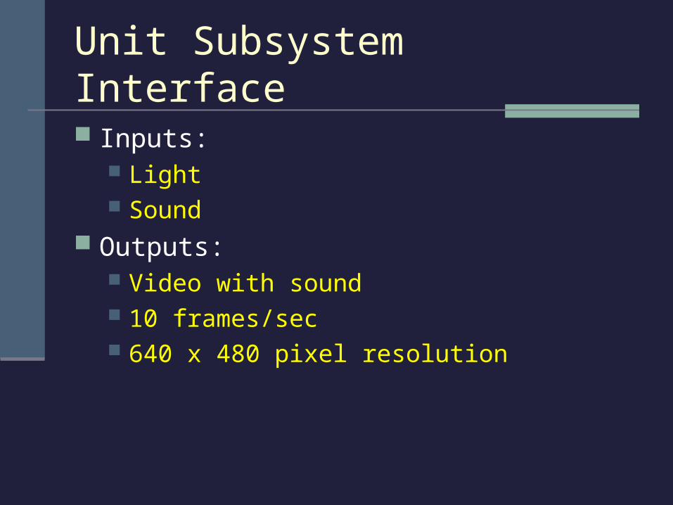
Unit Subsystem Interface
Inputs: Light Sound
Outputs: Video with sound 10 frames/sec 640 x 480 pixel resolution

VideoSat Insulation Subsystem
Purpose Protect from extreme cold of high altitude
environment Protect from impact during landing
(2GB)
Foam
Chemical heating packet
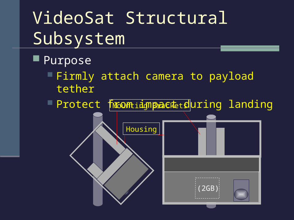
VideoSat Structural Subsystem
Purpose Firmly attach camera to payload tether Protect from impact during landing
(2GB)
Mounting Brackets
Housing

VideoSat System Interface
Most subsystem interfaces are mechanical in nature
An externalized switch will be mounted on the housing
Insulating Foam
Activation Switch
Camera UnitWire

VideoSat Mass Budget
Camera unit 38g Secure Digital card 2g Housing 300g Insulation 100g Chemical heating (3) 20g Structural and Hardware 150g
Estimated mass 610g

VideoSat Monetary Budget
Camera unit $ 150.00 Secure Digital card $ 100.00 Housing $ 30.00 Insulation $ 15.00 Chemical heating (3) $ 5.00 Structural and Hardware $ 100.00
Total $ 400.00
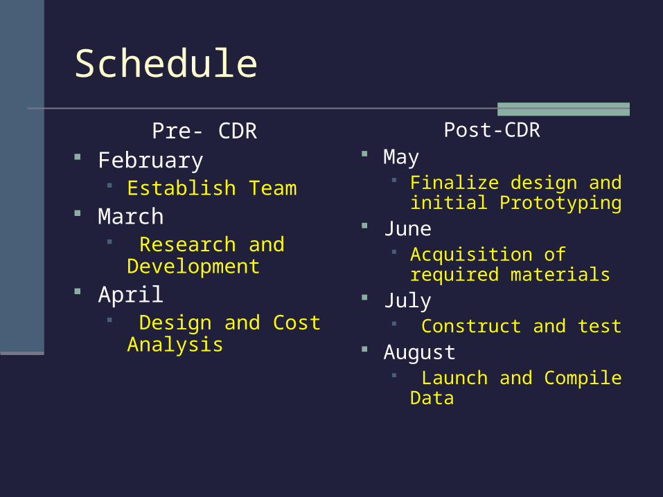
Schedule
Pre- CDR February
Establish Team March
Research and Development
April Design and Cost
Analysis
Post-CDR May
Finalize design and initial Prototyping
June Acquisition of required
materials July
Construct and test August
Launch and Compile Data

Any Questions?