demonstration of optical thickness measurement using
TRANSCRIPT

Journal of Physics Conference Series
OPEN ACCESS
Demonstration of optical thickness measurementusing multilayer cold neutron interferometerTo cite this article Y Seki et al 2012 J Phys Conf Ser 340 012039
View the article online for updates and enhancements
You may also likeSimulation Methods and Results of theSINQ Cold Neutron Source Upgrade StudyR M Bergmann U Filges D Kiselev etal
-
Advances in neutron radiography andtomographyM Strobl I Manke N Kardjilov et al
-
Multi-Grid detector for neutronspectroscopy results obtained on time-of-flight spectrometer CNCSM Anastasopoulos R Bebb K Berry etal
-
This content was downloaded from IP address 1751148635 on 19032022 at 0305
Demonstration of optical thickness measurement
using multilayer cold neutron interferometer
Y Seki1 J Uda2 H Funahashi2 M Kitaguchi3 M Hino3 Y Otake1 KTaketani4 and H M Shimizu4
1 RIKEN Wako Saitama 351-0198 Japan2 Institute for the Promotion of Excellence in Higher Education Kyoto University Kyoto606-8501 Japan3 Research Reactor Institute Kyoto University Kumatori Osaka 590-0494 Japan4 KEK Tsukuba Ibaraki 305-0801 Japan
E-mail ysekirikenjp
Abstract We have measured the optical thickness of a phase object for the first time usingmultilayer cold neutron interferometer The measured phase shift of 151 plusmn 19 wavelengthagreed with the expected value of 174 plusmn 07 wavelength due to an about 600-microm-thick siliconplate This demonstration reconfirmed that two paths in our new interferometer were completelyseparate and showed its applicability into various precise measurements
1 IntroductionThe multilayer mirror which can reflect cold and very cold neutrons is one of powerful neutronoptical devices for interferometry In addition to utilization of the long-wavelength neutronsaccurate alignment of multilayer mirrors with a large distance makes it possible to increaseinteraction time of neutrons with external potentials in the interferometer Such a multilayerinterferometer will be more sensitive in phase detection than the conventional silicon single-crystal interferometers and contribute to precise measurements of small interactions
We have recently developed a new type of multilayer neutron interferometer [1] Themultilayer interferometer consisted of a pair of beam splitting etalons (BSEs) (Figure 1) [2] withan air gap of 189 microm in spacing Two paths of the interferometer were completely separatedwith a center-to-center distance of 328 plusmn 9 microm at an incident angle of 099 plusmn 005 degrees whilethe previous multilayer interferometers had almost overlapped paths Clear interferograms withmaximum contrast of 67 were also successfully observed
This progress enables us to carry out experiments in more various configurations than beforeAs one of the configurations we demonstrated the optical thickness measurement of a phaseobject inserted into the one-side path using the multilayer interferometer
2 Experiment and discussionThe experimental setup is shown in Figure 2 A Jamin-type interferometer consisted of a pair ofBSEs In the interferometer the incident neutron waves were firstly converted to superposition ofthe spin-up and spin-down states by the polarizer and the first π2 RF spin flipper 1radic
2(|uarr⟩+ |darr⟩)
The superposition state was then split spatially by the first BSE For the symmetric geometry
5th European Conference on Neutron Scattering IOP PublishingJournal of Physics Conference Series 340 (2012) 012039 doi1010881742-65963401012039
Published under licence by IOP Publishing Ltd 1
nonmagnetic mirror
magnetic
mirror
magnetic
mirror (filter)
spin-up
spin-down
nonmagnetic mirror
magnetic
mirror
magnetic
mirror (filter)
spin-up
spin-down
54 mm
Figure 1 Schematic view (left) and photograph (right) of a beam splitting etalon (BSE) TheBSE separates the incident spin superposition state into two parallel paths with the spin-up andthe spin-down states
1st
BSE
2nd
BSE
π flipper
π2
flipper
polarizer
detector
neutron
beam
phase-
shifter-
coil
silicon
plate
π2
flipper
with
phase object
without
phase object
analyzer
slit
slitspin-up
spin-down
spin-down
spin-up
1st
BSE
2nd
BSE
π flipper
π2
flipper
polarizer
detector
neutron
beam
phase-
shifter-
coil
silicon
plate
π2
flipper
with
phase object
without
phase object
analyzer
slit
slitspin-up
spin-down
spin-down
spin-up
Figure 2 Experimental setup A weak magnetic field of about 10 G was generated verticallyby a guide coil all over the beam (omitted in the figure) The distance between two BSEs was300 mm
each spin state was reversed by the π RF spin flipper 1radic2(|uarr⟩+ |darr⟩) rarr 1radic
2
(|darr⟩+ e2iχπ |uarr⟩
)
where χπ is the phase of oscillating magnetic field in the π RF spin flipper relative to the otherπ2 RF spin flippers and the phase factor e2iχπ is due to the spin state transition [3] Afterthe spin reversal the spatially separate paths were recombined by the second BSE Finallythe spin state from each path was converted to the spin-up state by the second π2 RF spinflipper and the analyzer 1
2
(|uarr⟩+ e2iχπ |uarr⟩
) The interferograms were obtained by scanning the
relative phase χπ The change of χπ of 180 degrees gave a interferograms of one cycle Forthe present measurement a solenoid as a phase-shifter-coil was arranged behind the secondBSE The experiment was carried out at the monochromatic cold neutron beamline MINE2[4] of Japan Research Reactor No3 (JRR-3) in Japan Atomic Energy Agency (JAEA) Themean wavelength of the beam was λ0 = 088 nm with a bandwidth of 27 in full width athalf-maximum
As verified in the previous studies [5 6] the contrast of interferograms in the multilayerinterferometer is proportional to the coherence function Γ(σk L0) as
Γ(σk L0) = exp
[minus1
2(σkL0)
2]
(1)
when we use semi-monochromatic beam with a mean wavenumber k0 and the standard deviationσk of Gaussian distribution L0 is the optical path difference between the two paths and L0 ofzero makes an ldquoecho pointrdquo that is the maximum contrast point
5th European Conference on Neutron Scattering IOP PublishingJournal of Physics Conference Series 340 (2012) 012039 doi1010881742-65963401012039
2
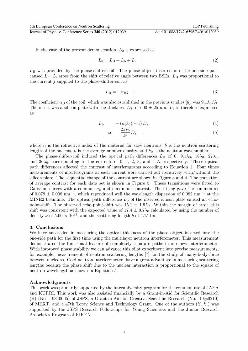
In the case of the present demonstration L0 is expressed as
L0 = LB + Lb + Li (2)
LB was provided by the phase-shifter-coil The phase object inserted into the one-side pathcaused Lb Li arose from the shift of relative angle between two BSEs LB was proportional tothe current j supplied to the phase-shifter-coil as
LB = minusαBj (3)
The coefficient αB of the coil which was also established in the previous studies [6] was 91λ0AThe insert was a silicon plate with the thickness DSi of 600 plusmn 25 microm Lb is therefore expressedas
Lb = minus (n(k0)minus 1)DSi (4)
≃ 2πνb
k20DSi (5)
where n is the refractive index of the material for slow neutrons b is the neutron scatteringlength of the nucleus ν is the average number density and k0 is the neutron wavenumber
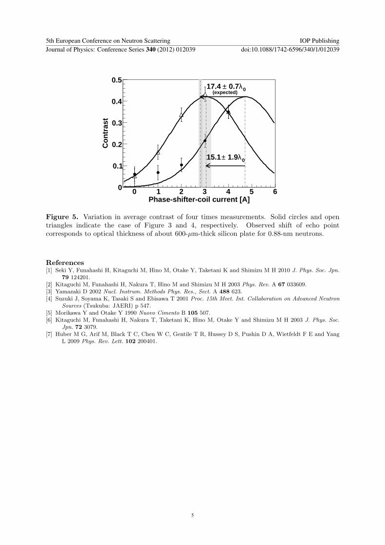
The phase-shifter-coil induced the optical path differences LB of 0 91λ0 18λ0 27λ0and 36λ0 corresponding to the currents of 0 1 2 3 and 4 A respectively These opticalpath differences affected the contrast of interferograms according to Equation 1 Four timesmeasurements of interferograms at each current were carried out iteratively withwithout thesilicon plate The sequential change of the contrast are shown in Figure 3 and 4 The transitionof average contrast for each data set is shown in Figure 5 These transitions were fitted toGaussian curves with a common σk and maximum contrast The fitting gave the common σkof 0079 plusmn 0008 nmminus1 which reproduced well the wavelength dispersion of 0082 nmminus1 at theMINE2 beamline The optical path difference Lb of the inserted silicon plate caused an echo-point-shift The observed echo-point-shift was 151 plusmn 19λ0 Within the margin of error thisshift was consistent with the expected value of 174 plusmn 07λ0 calculated by using the number ofdensity ν of 500 times 1022 and the scattering length b of 415 fm
3 ConclusionsWe have succeeded in measuring the optical thickness of the phase object inserted into theone-side path for the first time using the multilayer neutron interferometer This measurementdemonstrated the functional feature of completely separate paths in our new interferometerWith improved phase stability we can advance this pilot experiment into precise measurementsfor example measurement of neutron scattering lengths [7] for the study of many-body-forcebetween nucleons Cold neutron interferometers have a great advantage in measuring scatteringlengths because the phase shift due to the nuclear interaction is proportional to the square ofneutron wavelength as shown in Equation 5
AcknowledgmentsThis work was primarily supported by the interuniversity program for the common use of JAEAand KURRI This work was also assisted financially by a Grant-in-Aid for Scientific Research(B) (No 19340065) of JSPS a Grant-in-Aid for Creative Scientific Research (No 19gs0210)of MEXT and a 47th Toray Science and Technology Grant One of the authors (Y S) wassupported by the JSPS Research Fellowships for Young Scientists and the Junior ResearchAssociates Program of RIKEN
5th European Conference on Neutron Scattering IOP PublishingJournal of Physics Conference Series 340 (2012) 012039 doi1010881742-65963401012039
3
0 A 1 A 2 A 3 A 4 A
Run1
Run2
Run3
Run4
0
0
0
0
70
70
70
70
140
140
140
140
0 0 0 0 090 90 90 90 90180 180 180 180 180
flipper [deg]πPhase of RF magnetic field in
Cou
nts
75
snumberRun
Phase-shifter-coil current
Figure 3 Transition of interferograms due to additional optical path differences induced bymagnetic field of the phase-shifter-coil No phase object was inserted into any paths of theinterferometer All the data were fitted by sine curves with the cycle fixed at 180 degrees
0 A 1 A 2 A 3 A 4 A
Run1
Run2
Run3
Run4
0
0
0
0
70
70
70
70
140
140
140
140
0 0 0 0 090 90 90 90 90180 180 180 180 180
flipper [deg]πPhase of RF magnetic field in
Cou
nts
75
s
numberRun
Phase-shifter-coil current
Figure 4 Transition of interferograms due to additional optical path differences induced bymagnetic field of the phase-shifter-coil A silicon plate was inserted into the one-side path of theinterferometer All the data were also fitted by sine curves with the cycle fixed at 180 degrees
5th European Conference on Neutron Scattering IOP PublishingJournal of Physics Conference Series 340 (2012) 012039 doi1010881742-65963401012039
4
Phase-shifter-coil current [A]0 1 2 3 4 5 6
Con
tras
t
0
01
02
03
04
05
0λ 19plusmn151
0λ 07plusmn174 (expected)
Figure 5 Variation in average contrast of four times measurements Solid circles and opentriangles indicate the case of Figure 3 and 4 respectively Observed shift of echo pointcorresponds to optical thickness of about 600-microm-thick silicon plate for 088-nm neutrons
References[1] Seki Y Funahashi H Kitaguchi M Hino M Otake Y Taketani K and Shimizu M H 2010 J Phys Soc Jpn
79 124201[2] Kitaguchi M Funahashi H Nakura T Hino M and Shimizu M H 2003 Phys Rev A 67 033609[3] Yamazaki D 2002 Nucl Instrum Methods Phys Res Sect A 488 623[4] Suzuki J Soyama K Tasaki S and Ebisawa T 2001 Proc 15th Meet Int Collaboration on Advanced Neutron
Sources (Tsukuba JAERI) p 547[5] Morikawa Y and Otake Y 1990 Nuovo Cimento B 105 507[6] Kitaguchi M Funahashi H Nakura T Taketani K Hino M Otake Y and Shimizu M H 2003 J Phys Soc
Jpn 72 3079[7] Huber M G Arif M Black T C Chen W C Gentile T R Hussey D S Pushin D A Wietfeldt F E and Yang
L 2009 Phys Rev Lett 102 200401
5th European Conference on Neutron Scattering IOP PublishingJournal of Physics Conference Series 340 (2012) 012039 doi1010881742-65963401012039
5

Demonstration of optical thickness measurement
using multilayer cold neutron interferometer
Y Seki1 J Uda2 H Funahashi2 M Kitaguchi3 M Hino3 Y Otake1 KTaketani4 and H M Shimizu4
1 RIKEN Wako Saitama 351-0198 Japan2 Institute for the Promotion of Excellence in Higher Education Kyoto University Kyoto606-8501 Japan3 Research Reactor Institute Kyoto University Kumatori Osaka 590-0494 Japan4 KEK Tsukuba Ibaraki 305-0801 Japan
E-mail ysekirikenjp
Abstract We have measured the optical thickness of a phase object for the first time usingmultilayer cold neutron interferometer The measured phase shift of 151 plusmn 19 wavelengthagreed with the expected value of 174 plusmn 07 wavelength due to an about 600-microm-thick siliconplate This demonstration reconfirmed that two paths in our new interferometer were completelyseparate and showed its applicability into various precise measurements
1 IntroductionThe multilayer mirror which can reflect cold and very cold neutrons is one of powerful neutronoptical devices for interferometry In addition to utilization of the long-wavelength neutronsaccurate alignment of multilayer mirrors with a large distance makes it possible to increaseinteraction time of neutrons with external potentials in the interferometer Such a multilayerinterferometer will be more sensitive in phase detection than the conventional silicon single-crystal interferometers and contribute to precise measurements of small interactions
We have recently developed a new type of multilayer neutron interferometer [1] Themultilayer interferometer consisted of a pair of beam splitting etalons (BSEs) (Figure 1) [2] withan air gap of 189 microm in spacing Two paths of the interferometer were completely separatedwith a center-to-center distance of 328 plusmn 9 microm at an incident angle of 099 plusmn 005 degrees whilethe previous multilayer interferometers had almost overlapped paths Clear interferograms withmaximum contrast of 67 were also successfully observed
This progress enables us to carry out experiments in more various configurations than beforeAs one of the configurations we demonstrated the optical thickness measurement of a phaseobject inserted into the one-side path using the multilayer interferometer
2 Experiment and discussionThe experimental setup is shown in Figure 2 A Jamin-type interferometer consisted of a pair ofBSEs In the interferometer the incident neutron waves were firstly converted to superposition ofthe spin-up and spin-down states by the polarizer and the first π2 RF spin flipper 1radic
2(|uarr⟩+ |darr⟩)
The superposition state was then split spatially by the first BSE For the symmetric geometry
5th European Conference on Neutron Scattering IOP PublishingJournal of Physics Conference Series 340 (2012) 012039 doi1010881742-65963401012039
Published under licence by IOP Publishing Ltd 1
nonmagnetic mirror
magnetic
mirror
magnetic
mirror (filter)
spin-up
spin-down
nonmagnetic mirror
magnetic
mirror
magnetic
mirror (filter)
spin-up
spin-down
54 mm
Figure 1 Schematic view (left) and photograph (right) of a beam splitting etalon (BSE) TheBSE separates the incident spin superposition state into two parallel paths with the spin-up andthe spin-down states
1st
BSE
2nd
BSE
π flipper
π2
flipper
polarizer
detector
neutron
beam
phase-
shifter-
coil
silicon
plate
π2
flipper
with
phase object
without
phase object
analyzer
slit
slitspin-up
spin-down
spin-down
spin-up
1st
BSE
2nd
BSE
π flipper
π2
flipper
polarizer
detector
neutron
beam
phase-
shifter-
coil
silicon
plate
π2
flipper
with
phase object
without
phase object
analyzer
slit
slitspin-up
spin-down
spin-down
spin-up
Figure 2 Experimental setup A weak magnetic field of about 10 G was generated verticallyby a guide coil all over the beam (omitted in the figure) The distance between two BSEs was300 mm
each spin state was reversed by the π RF spin flipper 1radic2(|uarr⟩+ |darr⟩) rarr 1radic
2
(|darr⟩+ e2iχπ |uarr⟩
)
where χπ is the phase of oscillating magnetic field in the π RF spin flipper relative to the otherπ2 RF spin flippers and the phase factor e2iχπ is due to the spin state transition [3] Afterthe spin reversal the spatially separate paths were recombined by the second BSE Finallythe spin state from each path was converted to the spin-up state by the second π2 RF spinflipper and the analyzer 1
2
(|uarr⟩+ e2iχπ |uarr⟩
) The interferograms were obtained by scanning the
relative phase χπ The change of χπ of 180 degrees gave a interferograms of one cycle Forthe present measurement a solenoid as a phase-shifter-coil was arranged behind the secondBSE The experiment was carried out at the monochromatic cold neutron beamline MINE2[4] of Japan Research Reactor No3 (JRR-3) in Japan Atomic Energy Agency (JAEA) Themean wavelength of the beam was λ0 = 088 nm with a bandwidth of 27 in full width athalf-maximum
As verified in the previous studies [5 6] the contrast of interferograms in the multilayerinterferometer is proportional to the coherence function Γ(σk L0) as
Γ(σk L0) = exp
[minus1
2(σkL0)
2]
(1)
when we use semi-monochromatic beam with a mean wavenumber k0 and the standard deviationσk of Gaussian distribution L0 is the optical path difference between the two paths and L0 ofzero makes an ldquoecho pointrdquo that is the maximum contrast point
5th European Conference on Neutron Scattering IOP PublishingJournal of Physics Conference Series 340 (2012) 012039 doi1010881742-65963401012039
2
In the case of the present demonstration L0 is expressed as
L0 = LB + Lb + Li (2)
LB was provided by the phase-shifter-coil The phase object inserted into the one-side pathcaused Lb Li arose from the shift of relative angle between two BSEs LB was proportional tothe current j supplied to the phase-shifter-coil as
LB = minusαBj (3)
The coefficient αB of the coil which was also established in the previous studies [6] was 91λ0AThe insert was a silicon plate with the thickness DSi of 600 plusmn 25 microm Lb is therefore expressedas
Lb = minus (n(k0)minus 1)DSi (4)
≃ 2πνb
k20DSi (5)
where n is the refractive index of the material for slow neutrons b is the neutron scatteringlength of the nucleus ν is the average number density and k0 is the neutron wavenumber
The phase-shifter-coil induced the optical path differences LB of 0 91λ0 18λ0 27λ0and 36λ0 corresponding to the currents of 0 1 2 3 and 4 A respectively These opticalpath differences affected the contrast of interferograms according to Equation 1 Four timesmeasurements of interferograms at each current were carried out iteratively withwithout thesilicon plate The sequential change of the contrast are shown in Figure 3 and 4 The transitionof average contrast for each data set is shown in Figure 5 These transitions were fitted toGaussian curves with a common σk and maximum contrast The fitting gave the common σkof 0079 plusmn 0008 nmminus1 which reproduced well the wavelength dispersion of 0082 nmminus1 at theMINE2 beamline The optical path difference Lb of the inserted silicon plate caused an echo-point-shift The observed echo-point-shift was 151 plusmn 19λ0 Within the margin of error thisshift was consistent with the expected value of 174 plusmn 07λ0 calculated by using the number ofdensity ν of 500 times 1022 and the scattering length b of 415 fm
3 ConclusionsWe have succeeded in measuring the optical thickness of the phase object inserted into theone-side path for the first time using the multilayer neutron interferometer This measurementdemonstrated the functional feature of completely separate paths in our new interferometerWith improved phase stability we can advance this pilot experiment into precise measurementsfor example measurement of neutron scattering lengths [7] for the study of many-body-forcebetween nucleons Cold neutron interferometers have a great advantage in measuring scatteringlengths because the phase shift due to the nuclear interaction is proportional to the square ofneutron wavelength as shown in Equation 5
AcknowledgmentsThis work was primarily supported by the interuniversity program for the common use of JAEAand KURRI This work was also assisted financially by a Grant-in-Aid for Scientific Research(B) (No 19340065) of JSPS a Grant-in-Aid for Creative Scientific Research (No 19gs0210)of MEXT and a 47th Toray Science and Technology Grant One of the authors (Y S) wassupported by the JSPS Research Fellowships for Young Scientists and the Junior ResearchAssociates Program of RIKEN
5th European Conference on Neutron Scattering IOP PublishingJournal of Physics Conference Series 340 (2012) 012039 doi1010881742-65963401012039
3
0 A 1 A 2 A 3 A 4 A
Run1
Run2
Run3
Run4
0
0
0
0
70
70
70
70
140
140
140
140
0 0 0 0 090 90 90 90 90180 180 180 180 180
flipper [deg]πPhase of RF magnetic field in
Cou
nts
75
snumberRun
Phase-shifter-coil current
Figure 3 Transition of interferograms due to additional optical path differences induced bymagnetic field of the phase-shifter-coil No phase object was inserted into any paths of theinterferometer All the data were fitted by sine curves with the cycle fixed at 180 degrees
0 A 1 A 2 A 3 A 4 A
Run1
Run2
Run3
Run4
0
0
0
0
70
70
70
70
140
140
140
140
0 0 0 0 090 90 90 90 90180 180 180 180 180
flipper [deg]πPhase of RF magnetic field in
Cou
nts
75
s
numberRun
Phase-shifter-coil current
Figure 4 Transition of interferograms due to additional optical path differences induced bymagnetic field of the phase-shifter-coil A silicon plate was inserted into the one-side path of theinterferometer All the data were also fitted by sine curves with the cycle fixed at 180 degrees
5th European Conference on Neutron Scattering IOP PublishingJournal of Physics Conference Series 340 (2012) 012039 doi1010881742-65963401012039
4
Phase-shifter-coil current [A]0 1 2 3 4 5 6
Con
tras
t
0
01
02
03
04
05
0λ 19plusmn151
0λ 07plusmn174 (expected)
Figure 5 Variation in average contrast of four times measurements Solid circles and opentriangles indicate the case of Figure 3 and 4 respectively Observed shift of echo pointcorresponds to optical thickness of about 600-microm-thick silicon plate for 088-nm neutrons
References[1] Seki Y Funahashi H Kitaguchi M Hino M Otake Y Taketani K and Shimizu M H 2010 J Phys Soc Jpn
79 124201[2] Kitaguchi M Funahashi H Nakura T Hino M and Shimizu M H 2003 Phys Rev A 67 033609[3] Yamazaki D 2002 Nucl Instrum Methods Phys Res Sect A 488 623[4] Suzuki J Soyama K Tasaki S and Ebisawa T 2001 Proc 15th Meet Int Collaboration on Advanced Neutron
Sources (Tsukuba JAERI) p 547[5] Morikawa Y and Otake Y 1990 Nuovo Cimento B 105 507[6] Kitaguchi M Funahashi H Nakura T Taketani K Hino M Otake Y and Shimizu M H 2003 J Phys Soc
Jpn 72 3079[7] Huber M G Arif M Black T C Chen W C Gentile T R Hussey D S Pushin D A Wietfeldt F E and Yang
L 2009 Phys Rev Lett 102 200401
5th European Conference on Neutron Scattering IOP PublishingJournal of Physics Conference Series 340 (2012) 012039 doi1010881742-65963401012039
5

nonmagnetic mirror
magnetic
mirror
magnetic
mirror (filter)
spin-up
spin-down
nonmagnetic mirror
magnetic
mirror
magnetic
mirror (filter)
spin-up
spin-down
54 mm
Figure 1 Schematic view (left) and photograph (right) of a beam splitting etalon (BSE) TheBSE separates the incident spin superposition state into two parallel paths with the spin-up andthe spin-down states
1st
BSE
2nd
BSE
π flipper
π2
flipper
polarizer
detector
neutron
beam
phase-
shifter-
coil
silicon
plate
π2
flipper
with
phase object
without
phase object
analyzer
slit
slitspin-up
spin-down
spin-down
spin-up
1st
BSE
2nd
BSE
π flipper
π2
flipper
polarizer
detector
neutron
beam
phase-
shifter-
coil
silicon
plate
π2
flipper
with
phase object
without
phase object
analyzer
slit
slitspin-up
spin-down
spin-down
spin-up
Figure 2 Experimental setup A weak magnetic field of about 10 G was generated verticallyby a guide coil all over the beam (omitted in the figure) The distance between two BSEs was300 mm
each spin state was reversed by the π RF spin flipper 1radic2(|uarr⟩+ |darr⟩) rarr 1radic
2
(|darr⟩+ e2iχπ |uarr⟩
)
where χπ is the phase of oscillating magnetic field in the π RF spin flipper relative to the otherπ2 RF spin flippers and the phase factor e2iχπ is due to the spin state transition [3] Afterthe spin reversal the spatially separate paths were recombined by the second BSE Finallythe spin state from each path was converted to the spin-up state by the second π2 RF spinflipper and the analyzer 1
2
(|uarr⟩+ e2iχπ |uarr⟩
) The interferograms were obtained by scanning the
relative phase χπ The change of χπ of 180 degrees gave a interferograms of one cycle Forthe present measurement a solenoid as a phase-shifter-coil was arranged behind the secondBSE The experiment was carried out at the monochromatic cold neutron beamline MINE2[4] of Japan Research Reactor No3 (JRR-3) in Japan Atomic Energy Agency (JAEA) Themean wavelength of the beam was λ0 = 088 nm with a bandwidth of 27 in full width athalf-maximum
As verified in the previous studies [5 6] the contrast of interferograms in the multilayerinterferometer is proportional to the coherence function Γ(σk L0) as
Γ(σk L0) = exp
[minus1
2(σkL0)
2]
(1)
when we use semi-monochromatic beam with a mean wavenumber k0 and the standard deviationσk of Gaussian distribution L0 is the optical path difference between the two paths and L0 ofzero makes an ldquoecho pointrdquo that is the maximum contrast point
5th European Conference on Neutron Scattering IOP PublishingJournal of Physics Conference Series 340 (2012) 012039 doi1010881742-65963401012039
2
In the case of the present demonstration L0 is expressed as
L0 = LB + Lb + Li (2)
LB was provided by the phase-shifter-coil The phase object inserted into the one-side pathcaused Lb Li arose from the shift of relative angle between two BSEs LB was proportional tothe current j supplied to the phase-shifter-coil as
LB = minusαBj (3)
The coefficient αB of the coil which was also established in the previous studies [6] was 91λ0AThe insert was a silicon plate with the thickness DSi of 600 plusmn 25 microm Lb is therefore expressedas
Lb = minus (n(k0)minus 1)DSi (4)
≃ 2πνb
k20DSi (5)
where n is the refractive index of the material for slow neutrons b is the neutron scatteringlength of the nucleus ν is the average number density and k0 is the neutron wavenumber
The phase-shifter-coil induced the optical path differences LB of 0 91λ0 18λ0 27λ0and 36λ0 corresponding to the currents of 0 1 2 3 and 4 A respectively These opticalpath differences affected the contrast of interferograms according to Equation 1 Four timesmeasurements of interferograms at each current were carried out iteratively withwithout thesilicon plate The sequential change of the contrast are shown in Figure 3 and 4 The transitionof average contrast for each data set is shown in Figure 5 These transitions were fitted toGaussian curves with a common σk and maximum contrast The fitting gave the common σkof 0079 plusmn 0008 nmminus1 which reproduced well the wavelength dispersion of 0082 nmminus1 at theMINE2 beamline The optical path difference Lb of the inserted silicon plate caused an echo-point-shift The observed echo-point-shift was 151 plusmn 19λ0 Within the margin of error thisshift was consistent with the expected value of 174 plusmn 07λ0 calculated by using the number ofdensity ν of 500 times 1022 and the scattering length b of 415 fm
3 ConclusionsWe have succeeded in measuring the optical thickness of the phase object inserted into theone-side path for the first time using the multilayer neutron interferometer This measurementdemonstrated the functional feature of completely separate paths in our new interferometerWith improved phase stability we can advance this pilot experiment into precise measurementsfor example measurement of neutron scattering lengths [7] for the study of many-body-forcebetween nucleons Cold neutron interferometers have a great advantage in measuring scatteringlengths because the phase shift due to the nuclear interaction is proportional to the square ofneutron wavelength as shown in Equation 5
AcknowledgmentsThis work was primarily supported by the interuniversity program for the common use of JAEAand KURRI This work was also assisted financially by a Grant-in-Aid for Scientific Research(B) (No 19340065) of JSPS a Grant-in-Aid for Creative Scientific Research (No 19gs0210)of MEXT and a 47th Toray Science and Technology Grant One of the authors (Y S) wassupported by the JSPS Research Fellowships for Young Scientists and the Junior ResearchAssociates Program of RIKEN
5th European Conference on Neutron Scattering IOP PublishingJournal of Physics Conference Series 340 (2012) 012039 doi1010881742-65963401012039
3
0 A 1 A 2 A 3 A 4 A
Run1
Run2
Run3
Run4
0
0
0
0
70
70
70
70
140
140
140
140
0 0 0 0 090 90 90 90 90180 180 180 180 180
flipper [deg]πPhase of RF magnetic field in
Cou
nts
75
snumberRun
Phase-shifter-coil current
Figure 3 Transition of interferograms due to additional optical path differences induced bymagnetic field of the phase-shifter-coil No phase object was inserted into any paths of theinterferometer All the data were fitted by sine curves with the cycle fixed at 180 degrees
0 A 1 A 2 A 3 A 4 A
Run1
Run2
Run3
Run4
0
0
0
0
70
70
70
70
140
140
140
140
0 0 0 0 090 90 90 90 90180 180 180 180 180
flipper [deg]πPhase of RF magnetic field in
Cou
nts
75
s
numberRun
Phase-shifter-coil current
Figure 4 Transition of interferograms due to additional optical path differences induced bymagnetic field of the phase-shifter-coil A silicon plate was inserted into the one-side path of theinterferometer All the data were also fitted by sine curves with the cycle fixed at 180 degrees
5th European Conference on Neutron Scattering IOP PublishingJournal of Physics Conference Series 340 (2012) 012039 doi1010881742-65963401012039
4
Phase-shifter-coil current [A]0 1 2 3 4 5 6
Con
tras
t
0
01
02
03
04
05
0λ 19plusmn151
0λ 07plusmn174 (expected)
Figure 5 Variation in average contrast of four times measurements Solid circles and opentriangles indicate the case of Figure 3 and 4 respectively Observed shift of echo pointcorresponds to optical thickness of about 600-microm-thick silicon plate for 088-nm neutrons
References[1] Seki Y Funahashi H Kitaguchi M Hino M Otake Y Taketani K and Shimizu M H 2010 J Phys Soc Jpn
79 124201[2] Kitaguchi M Funahashi H Nakura T Hino M and Shimizu M H 2003 Phys Rev A 67 033609[3] Yamazaki D 2002 Nucl Instrum Methods Phys Res Sect A 488 623[4] Suzuki J Soyama K Tasaki S and Ebisawa T 2001 Proc 15th Meet Int Collaboration on Advanced Neutron
Sources (Tsukuba JAERI) p 547[5] Morikawa Y and Otake Y 1990 Nuovo Cimento B 105 507[6] Kitaguchi M Funahashi H Nakura T Taketani K Hino M Otake Y and Shimizu M H 2003 J Phys Soc
Jpn 72 3079[7] Huber M G Arif M Black T C Chen W C Gentile T R Hussey D S Pushin D A Wietfeldt F E and Yang
L 2009 Phys Rev Lett 102 200401
5th European Conference on Neutron Scattering IOP PublishingJournal of Physics Conference Series 340 (2012) 012039 doi1010881742-65963401012039
5

0 A 1 A 2 A 3 A 4 A
Run1
Run2
Run3
Run4
0
0
0
0
70
70
70
70
140
140
140
140
0 0 0 0 090 90 90 90 90180 180 180 180 180
flipper [deg]πPhase of RF magnetic field in
Cou
nts
75
snumberRun
Phase-shifter-coil current
Figure 3 Transition of interferograms due to additional optical path differences induced bymagnetic field of the phase-shifter-coil No phase object was inserted into any paths of theinterferometer All the data were fitted by sine curves with the cycle fixed at 180 degrees
0 A 1 A 2 A 3 A 4 A
Run1
Run2
Run3
Run4
0
0
0
0
70
70
70
70
140
140
140
140
0 0 0 0 090 90 90 90 90180 180 180 180 180
flipper [deg]πPhase of RF magnetic field in
Cou
nts
75
s
numberRun
Phase-shifter-coil current
Figure 4 Transition of interferograms due to additional optical path differences induced bymagnetic field of the phase-shifter-coil A silicon plate was inserted into the one-side path of theinterferometer All the data were also fitted by sine curves with the cycle fixed at 180 degrees
5th European Conference on Neutron Scattering IOP PublishingJournal of Physics Conference Series 340 (2012) 012039 doi1010881742-65963401012039
4
Phase-shifter-coil current [A]0 1 2 3 4 5 6
Con
tras
t
0
01
02
03
04
05
0λ 19plusmn151
0λ 07plusmn174 (expected)
Figure 5 Variation in average contrast of four times measurements Solid circles and opentriangles indicate the case of Figure 3 and 4 respectively Observed shift of echo pointcorresponds to optical thickness of about 600-microm-thick silicon plate for 088-nm neutrons
References[1] Seki Y Funahashi H Kitaguchi M Hino M Otake Y Taketani K and Shimizu M H 2010 J Phys Soc Jpn
79 124201[2] Kitaguchi M Funahashi H Nakura T Hino M and Shimizu M H 2003 Phys Rev A 67 033609[3] Yamazaki D 2002 Nucl Instrum Methods Phys Res Sect A 488 623[4] Suzuki J Soyama K Tasaki S and Ebisawa T 2001 Proc 15th Meet Int Collaboration on Advanced Neutron
Sources (Tsukuba JAERI) p 547[5] Morikawa Y and Otake Y 1990 Nuovo Cimento B 105 507[6] Kitaguchi M Funahashi H Nakura T Taketani K Hino M Otake Y and Shimizu M H 2003 J Phys Soc
Jpn 72 3079[7] Huber M G Arif M Black T C Chen W C Gentile T R Hussey D S Pushin D A Wietfeldt F E and Yang
L 2009 Phys Rev Lett 102 200401
5th European Conference on Neutron Scattering IOP PublishingJournal of Physics Conference Series 340 (2012) 012039 doi1010881742-65963401012039
5