dehumidifier system
TRANSCRIPT

Dehumidification
BALASUBRAMANIAN STALIN U080896A

Objectives
To Design, Fabricate & Performance Evaluation of an Waste Heat Driven Desiccant De-Humidifier
Silica Gel ( Absorbent)
Process Cycles Absorption ( Moisture Air ) & Regeneration (Hot
Air)

De-Humidifier Schematic

Chamber Design
Made up of 2.5mm thick sheet of aluminum.Houses the cake assemblyWater flow tubes from the two heat exchangers
are connected to the cake assembly through the chamber side walls.
Air Inlet & Outlet Pipe Sections Connected at Both Ends

Cake Assembly
Made in Square Shape of 250mmX150mmX15mm SizeConfigured as Heat Exchanger with fins and single pass tubeSilica gel of 0.3mm diameter filled in between the fins space (375grams) Wire mesh is soldered on both sides of the cake assembly to hold the silica
gel intact and prevent atmospheric air leakage 2 no's of cake is assembled to the chamber in such a way that the process
enters and exits through the wire mesh only

Humidity Station
Placed in Tank outlet, Chamber Inlet and Chamber outlet sections Kimo Sensor ( Measures – RH% and Temp) Dry bulb Temperature and Wet bulb Temperature Humidity Ratio found from Psychrometric chart using the values obtained
from the readings at these stations and hence performance evaluation is obtained

Water Tank
Water is filled and heated to 65deg C to create moisture Fitted with condensing cone plate – numerous holes were made to water
droplets and pass only the moisture air to the system
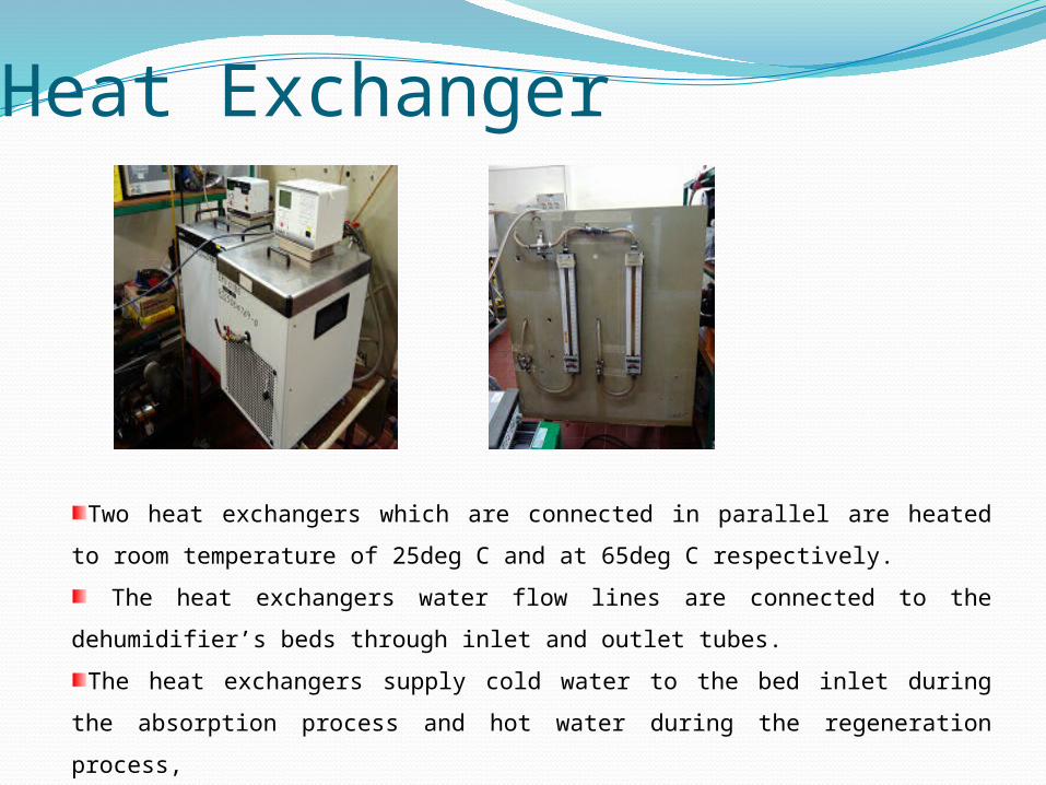
Heat Exchanger
Two heat exchangers which are connected in parallel are heated to room temperature of 25deg C and at 65deg C respectively.
The heat exchangers water flow lines are connected to the dehumidifier’s beds through inlet and outlet tubes.
The heat exchangers supply cold water to the bed inlet during the absorption process and hot water during the regeneration process,
and these processes are carried out by operating the directional control valves manually.

Suction BlowerSuction blower as shown in fig is
assembled to the systems air outlet duct section in-order to draw the process air and pump away the dehumidified air from the system to the outlet where it was needed.
The flow is inside the blower is kept at laminar flow to have a steady desired level of de humidified air. (36Kg/hr)

Agilent Data Logger
The software is a Windows®-based application. Uses spreadsheet environment to define measurement data to be
collected. Simply identify the measurements which are to be acquired, initiate the
process, and see the data displayed in real-time. The new quick graph feature provides easy to use graphing with many
options for graphing the data.

Principle of Operation
The dehumidification is been carried out with combination of two different process which is carried out alternatively in a given time cycle and they are named as Regeneration process and Absorption process

Absorption Process
Adsorption is a process , where moisture is condensed and held on the surface of the material without any change in the physical or chemical structure of the material.
The adsorbent material can be reactivated by heat.
Silica gel - SiO2 - is a hard, adsorbent, crystalline substance and
very porous.
Voids are about 50 - 70% by volume and adsorb water up to 40% of its own mass.
The bulk density of silica gel is 480 - 720 kg/m3.
The specific heat capacity is 1.13 kJ/kgK.

Absorption ProcessWater in tank is heated to 65deg C to create moisture air
The moisture air is then passed through the condenser assembly inside the water tank
Where the condensed water droplets will drip down to the tank and only moisture air passes through the
holes on it
The moisture air then pass through the humidity station located at the outlet of the tank and inlet of the
chamber where measurements ( dbt, wbt, RH% & T ) were observed through the thermocouples and the KIMO
sensors
Heat exchanger supply water flow to the bed at 25deg C
Moisture process air passes through the beds impregnated with silica gel
The silica gel absorbs the moisture in air
Then the dehumidified air pass through the humidity station located at the exit of the chamber and again the
measurements are observed
The de-humidified air is then fed to the required space through the suction blower which is fitted into the
system’s flow line
Process air leaves the dehumidifier as dry air.

Regeneration Process
Regeneration cycle helps to bring the silica gel filled in the beds achieve its initial state or completely dry so that it will be used to absorb the moisture in the air for the subsequent cycle of operation.
Here the heat exchanger which is operating at 65deg C is used to fed the hot water to the two cake assembly

Regeneration ProcessAir is drawn into the chamber through atmospheric air intake section
Heated to high temperature of 70deg C through heating element
Water tank is isolated from the chamber
Heat exchanger supply water flow to bed at 65deg C
The hot air then pass through the humidity station located at the inlet of the
chamber where measurements ( dbt, wbt, RH% & T ) were observed
Hot air then passes through the beds and silica gel releases the moisture from
the bed
The hot air then pass through the humidity station located at the outlet of the
chamber where measurements ( dbt, wbt, RH% & T ) were observed
Regeneration air leaves the dehumidifier as warm wet air.

Experimental Results
0.00 200.00 400.00 600.00 800.00 1000.00 1200.00 1400.00 1600.00 1800.00 2000.000.00
10.0020.0030.0040.0050.0060.0070.00
Hot Air Temp @ Chamber Outlet
Temp
Initial Condition
The chart shows the temperature gradient of the desiccant bed when hot air flows through the cold bed, the silica gel absorbs the heat from hot air and then releases the moisture from it and thus gets completely dried.
After 750secs the temperature starts to increases gradually, during this heating period, the silica gel is attaining its dried stature and the system is ready for the absorption cycle or to dehumidify the air

Experimental Results Initial Condition
It illustrate that the effective period of adsorption ranges between 10 and 12 min for the presented hot air conditions. After this period, it is noticed that the exit humidity of dehumidified air seems to be nearly constant. This means that successive adsorption will consume more power for the air blowing system

Experimental Results Process Cycle
0 1000 2000 3000 4000 5000 60002627282930313233
Humidity Ratio ω ( Grams Moisture /Kg Dry Air)@ System
OutletHumidity Ratio ω ( Grams Moisture /Kg Dry Air)@ System Outlet
0 1000 2000 3000 4000 5000 600020
22
24
26
28
30
32
34
36
38
Humididty Ratio By Interplat-ing Dbt & WbtHumidity Ratio By KIMO Sensor

Experimental Results
Approximately 5 to 10gms Moisture /Kg Dry Air is been reduced
0 1000 2000 3000 4000 5000 60000
5
10
15
20
25
30
35
Humidity Ratio ω ( Grams Moisture /Kg Dry Air)@ System OutletHumidity Ratio ω ( Grams Moisture /Kg Dry Air) @ System InletHumidity Ratio ω ( Grams Moisture /Kg Dry Air) @ Tank Outlet
0 1000 2000 3000 4000 5000 60002627282930313233
Humidity Ratio ω ( Grams Moisture /Kg Dry Air)@ System
OutletHumidity Ratio ω ( Grams Moisture /Kg Dry Air)@ System Outlet

Conclusion Absorption / Desorption operations of a packed bed have been
investigated. Silica gel applied as the working desiccant.
The following conclusions can be summarized: 1. The absorption rate has its maximum value at the beginning of
absorption, and then rapidly decreases to its minimum value for a period of time. This period is dependent on the bed parameters and air inlet conditions.
2. The average absolute moisture removal is 5 to 10gms/Kg dry Air 3. The start-up period of desorption is discussed and highlighted. It is found that a transient period 720secs (after few tests )from absorption to desorption is needed. 4. The bed design parameters can be selected in accordance with the objective function of the process. To maximize the drop in air humidity it is recommended to use desiccant bed with higher bed sizes.

Q & A