deepwater drilling challenges - 2hoffshore.com · introduction present the challenges of moving to...
TRANSCRIPT


Deepwater Drilling Riser Technical Challenges
Ben Middleditch
October 2011
Learn more at www.2hoffshore.com

Learn more at www.2hoffshore.com
2H - an ACTEON company
Learn more at www.2hoffshore.com
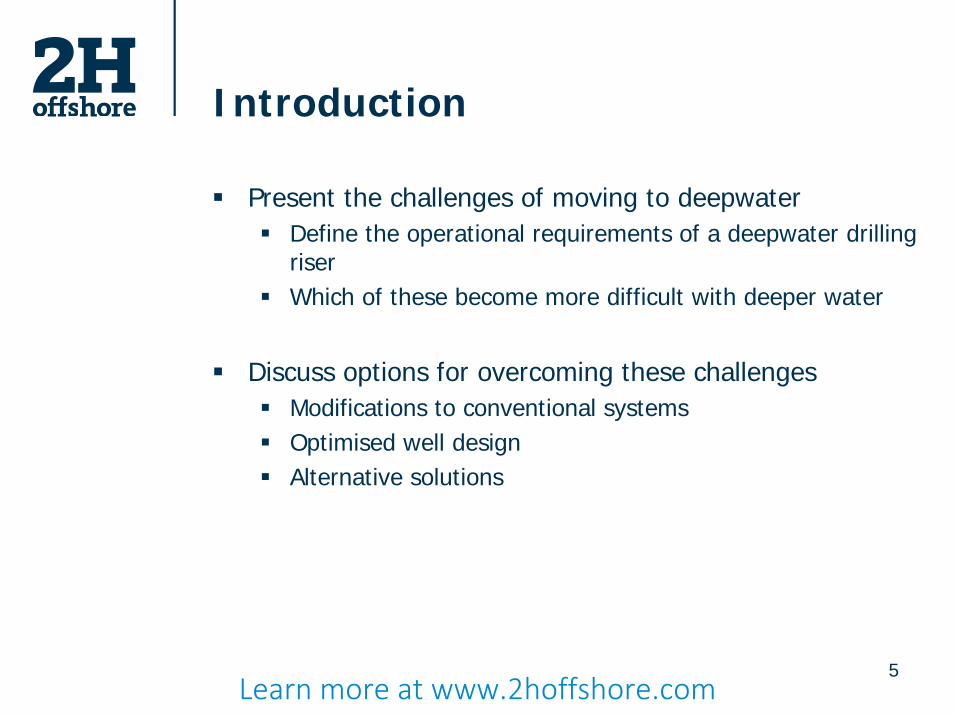
Introduction
Present the challenges of moving to deepwaterDefine the operational requirements of a deepwater drilling riserWhich of these become more difficult with deeper water
Discuss options for overcoming these challengesModifications to conventional systemsOptimised well designAlternative solutions
5Learn more at www.2hoffshore.com
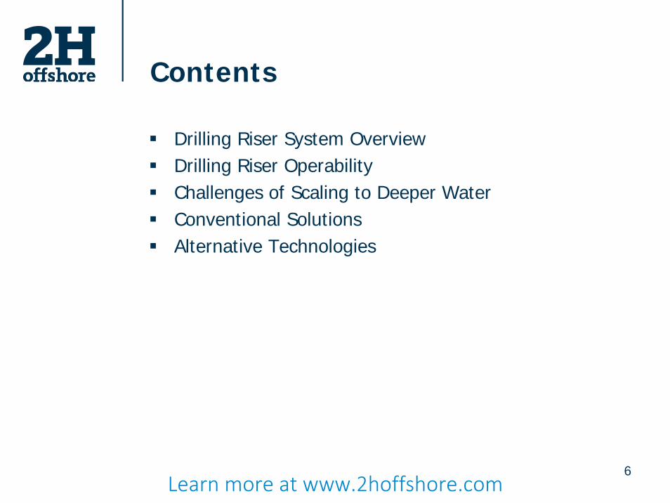
Contents
Drilling Riser System OverviewDrilling Riser OperabilityChallenges of Scaling to Deeper WaterConventional SolutionsAlternative Technologies
6Learn more at www.2hoffshore.com

ConventionalDeepwater LP Drilling Riser
Derrick
Drill Floor
Riser Tensioners
Telescopic Joint
Upper Flex Joint
Riser Joints
Lower Flex Joint
LMRP
BOP
Learn more at www.2hoffshore.com

Conventional LP Drilling Risers
Typically 21” OD marine riser80ksi steelRange of Connector TypesExternal Auxiliary LinesBuoyancy Modules to 10,000ft18-3/4” Subsea BOP system
8Learn more at www.2hoffshore.com

Loading
Learn more at www.2hoffshore.com

BOP
Conductor
Lower Flex Joint
Riser
Flex Joint Rotation
Drilling Riser Systems:Static Loading
10
Drift-offDrive-off
current
On Station
Learn more at www.2hoffshore.com
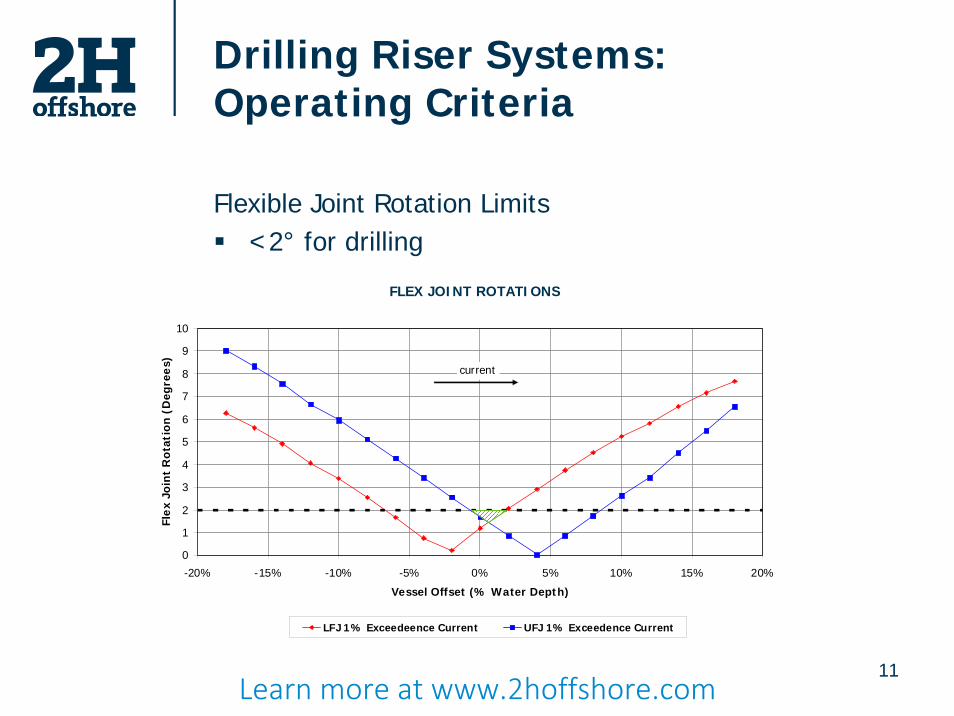
Drilling Riser Systems:Operating Criteria
Flexible Joint Rotation Limits<2° for drilling
11
FLEX JOINT ROTATIONS
0
1
2
3
4
5
6
7
8
9
10
-20% -15% -10% -5% 0% 5% 10% 15% 20%
Vessel Offset (% Water Depth)
Fle
x Jo
int
Ro
tati
on
(D
egre
es)
LFJ 1% Exceedeence Current UFJ 1% Exceedence Current
current
Learn more at www.2hoffshore.com

Drilling Riser Systems:Operating Criteria
Flexible Joint Rotation Limits (<2° for drilling)Increasing top tensions increase operability
12
TENSION OPTIMISATION - LOWER FLEX JOINT RESPONSE0% Vessel Offset, 1-Year Return Current
0.0
0.5
1.0
1.5
2.0
2.5
3.0
3.5
4.0
90 190 290 390 490 590 690Base Tension (Te)
Fle
x Jo
int
rota
tio
n (
deg
)
354 454 554 654 754 854
Top Tension (Te)
1 Year Return Period 0.1% Exceedence 0.5% Exceedence1% Exceedence 5% Exceedence 10% Exceedence
Learn more at www.2hoffshore.com

Drilling Riser Systems:Operating Envelopes
Flex jointrotation
Conductorstress
Tensionerstroke out
RISER OPERATING ENVELOPE WITH CURRENT ONLY400kips Base Tension - Mud Filled 1.35SG - Soft Soil Profile
0.0
0.2
0.4
0.6
0.8
1.0
1.2
-20 -15 -10 -5 0 5 10 15 20
Vessel Offset (% of water depth)
Surf
ace
Cu
rren
t V
eloc
ity
(m/s
)
SurvivalFJ Rotation < 90% maxVM / Yield Stress < 1.0
Connected (Not Drilling)FJ Rotation < 90% maxVM / Yield Stress < 0.8
DrillingFJ Rotation < 2deg (mean)FJ Rotation < 4deg (max)VM / Yield Stress < 0.67
Stroke Limit1 Year Current1% Current
Learn more at www.2hoffshore.com

Moving to Deeper Water
14Learn more at www.2hoffshore.com

Scaling to Deeper Water:Top Tension Capacity
Increased Riser Top TensionIncreased Vessel Tensioner Requirement
15
Longer riser string
Heavier riser string
Increased volume of drilling mud
Increased internal burst pressure (HP reservoirs)
Increased external hydrostatic collapse pressure
Increased riser pipe wall thickness
Higher axial stress
Limited by minimum ID for drill bits & casing hangers
Learn more at www.2hoffshore.com

Scaling to Deeper Water:Drilling Riser Buoyancy
16
External buoyancy attached to riser joints reduce the in water mass of the riser string
Typically made from syntactic foamGlass or ceramic hollow micro spheresSuspended in a polymer matrix
External durable coating
Learn more at www.2hoffshore.com

Scaling to Deeper Water:Buoyancy Impacts
17
Greater deck space usageHandling difficultiesIncreased riser dragReduced buoyancy effectiveness at greater depthsRotary table opening size limit
Learn more at www.2hoffshore.com

Scaling to Deeper Water:Buoyancy Impacts
18
Reduced buoyancy effectiveness at greater depths
REQUIRED VESSEL TENSION CAPACITY WITH INCREASING WATER DEPTH21" OD x 7/8" wt Riser, 16ppg Mud Weight, 1000kips Overpull
0
200
400
600
800
1000
1200
1400
1600
600 800 1000 1200 1400 1600 1800 2000 2200 2400 2600 2800 3000 3200
Water Depth (m)
Req
uir
ed V
esse
l Ten
sio
n C
apac
ity
(Te)
0
500
1000
1500
2000
2500
3000
1970 2626 3282 3938 4594 5250 5906 6562 7218 7874 8530 9186 9842 10498
Water Depth (ft)
Req
uir
ed V
esse
l Ten
sio
n C
apac
ity
(kip
s)
Learn more at www.2hoffshore.com

Scaling to Deeper Water:Vortex Induced Vibration Fatigue
All bodies in current flows experience forcesWhen an in-line current causes the bodies to vibrate at a natural frequency in the cross-flow direction this is called VIVConstant vibration of the riser causes stress cycling, which causes fatigue damage on the riser, which can cause the riser to fail
Vortex
Learn more at www.2hoffshore.com

Scaling to Deeper Water:Vortex Induced Vibration Fatigue
Longer riser strings have lower natural frequenciesSo slow currents which may not excite a shallow water riser can excite the same diameter riser in deeper waterFor the same current speed higher frequencies can be excitedThese higher frequencies have greater curvatures and larger bending stress cycles
Learn more at www.2hoffshore.com

Conventional LP Drilling Risers
Deepwater IssuesHigh tension requirements (2500kips+ for 10,000ft)Buoyancy becomes less efficientHighly susceptible to VIV (Vortex Induced Vibration) Complex Choke / Kill line interaction and sealing due to large riser deflectionWorldwide lack of deepwater rigsHigh rig costRig availability will dictate development schedule
Learn more at www.2hoffshore.com

Solutions
22Learn more at www.2hoffshore.com

Conventional Solutions
New larger capacity rigsGreater deck capacityLarger tensioner systemsLarger rotary tables
Long term rig contracts
VIV suppressionStrakesDistributed buoyancyTension variation
Optimised well design23
Learn more at www.2hoffshore.com

Well Construction:Design for Fatigue Resistance
Optimise the choice of well components:Conductor sizeConductor joint lengthWeld quality
Construction variables:Wellhead stick-upCement shortfall
Impact of riser design:Operation modeSubsea component size
24Learn more at www.2hoffshore.com

Conductor to WellheadGirth Weld
Extension Girth Weld
Conductor Coupling
Conductor to Coupling Weld
Conductor
LMRP /BOP
Riser pipe
Well Construction:Design for Fatigue Resistance
Critical welds
25Learn more at www.2hoffshore.com

Lateral Load from Drilling Riser
26
Woodside - Omar 1 Drilling Riser and Conductor AnalysisBENDING MOMENT DISTRIBUTION ALONG CONDUCTOR
300kips Base Tension - 380 W.D. - 10 Year Current - Upper Bound Soil
-50
-40
-30
-20
-10
0
10
-12000 -8000 -4000 0 4000 8000 12000 16000 20000
Bending Moment (kNm)
Elev
atio
n a
bove
Sea
bed
(m)
-20% Offset -18% Offset -16% Offset -14% Offset
-12% Offset -10% Offset -8% Offset -4% Offset
0% Offset +4% Offset +8% Offset +10% Offset
+12% Offset +14% Offset +16% Offset +18% Offset
+20% Offset HDH4 Connector HAC D90 Connector
HAC Upper Joint HAC Lower Joint 36" x 1.5", 52ksi Conductor
36" x 1.5" Conductor
(52ksi)
BOPHDH4
LMRP
HAC Upper Joint HAC
D90
Wellhead
HAC Lower Joint
Learn more at www.2hoffshore.com

Effects of Conductor Sizes
30”x1.5” 36”x1.5” 36”x2.0” 38”x2.0”
27
Fatigue life increased by a factor of 5 with an upgrade from 30” OD to 36” OD
Learn more at www.2hoffshore.com

Effects of Weld Quality
28
Increase in fatigue life by a factor of 10 whenachieving a C class weld compared to an E class
MINIMUM UNFACTORED FATIGUE LIFE
1
10
100
1000
10000
C Class,SCF 1.1
C Class,SCF 1.3
D Class,SCF 1.1
D Class,SCF 1.3
E Class,SCF 1.1
E Class,SCF 1.3
F1 Class,SCF 1.1
F1 Class,SCF 1.3
Weld Class
Fati
gu
e Li
fe (
day
s)
Learn more at www.2hoffshore.com

Effects of Wellhead Stick-up
2m Stickup 40% - 50% better than 3m Stick-up
29Learn more at www.2hoffshore.com

Effects of Cement Shortfall
No cement shortfall 50% better than 2m cement shortfall
30Learn more at www.2hoffshore.com

Effects of Operating Mode
Drilling Mode(no Subsea tree)
Completion Mode(with Subsea tree)
Learn more at www.2hoffshore.com

Effects of Operating Mode
Completion Mode 3 times more damaging than Drilling Mode
Learn more at www.2hoffshore.com

Well Construction Findings
Larger LRMP & BOP stacks typical on deepwater drilling rigs have a detrimental affect on a wellhead fatigue performanceThis can be offset by:
Incorporating a larger diameter conductorChoosing conductor joint lengths based on peak lateral loadSpecifying better weld detailsUsing a rigid lock down wellheadEnsuring a good conductor cement jobEnsuring a low wellhead stick-up
33Learn more at www.2hoffshore.com
Alternative Solutions
Steel replacementsHP surface BOP drilling riserNear Surface BOP SystemsFree standing drilling riser
34Learn more at www.2hoffshore.com

Steel Replacements
Drilling Riser Joints including Choke & Kill LinesCompositeAluminiumTitanium
IssuesLower stiffness induces greater riser deflectionsLower wear resistance (composite & aluminium)Lower corrosion resistance (aluminium)Higher production costs
35Learn more at www.2hoffshore.com

HP Surface BOPDrilling Riser
Subsea ESD
Subsea Wellhead
13-3/8” Casing (typ.)
Surface BOP
Stress Joints
Telescopic Joint
Buoyancy Modules (Optional)
Flex-Joint
Tie-back connector
36Learn more at www.2hoffshore.com

HP Surface BOP Drilling Riser
13-5/8” 15ksi Surface BOPTypically 13-3/8” or 16” casingSubsea ESD for emergency disconnectionUse of additional buoyancy dependent on vessel tension capacity and water depthTop configuration to suit vessel (modifications may be required)Casing can be re-used or run downhole on next wellAllows lower spec / cost rigs to be used in deepwater applications
37Learn more at www.2hoffshore.com

Near Surface BOP Systems
Elevates BOP to near surface region (100m – 250m water depth)
Buoyancy tank used as ‘artificial seabed’
Standard rig marine riser and BOP used to surface
Large diameter tie-back casing (21”+) used to seabed
System can freestand with BOP in event of disconnect
Allows use of 3rd generation rigs for deepwater wells
38Learn more at www.2hoffshore.com

FreestandingDrillingRisers BOP
Upper disconnect package
LMRP and BOP
Aircans to support lower riser
Conventional lower riser
Conventional upper riser
LMRP
Aircan to support casing and BOP
Well casing
Tie-Back Connector
Learn more at www.2hoffshore.com

Summary
Scalability of conventional marine risers becomes increasing difficult with increasing water depthsNew purpose built rigs overcome the majority of these challenges, but their availability is limitedNew technologies are being championed which can allow the upgrading of older rigs for use in deeper waterProblems still exist such as VIV and other forms of fatigue that need to be considered in well planning
40Learn more at www.2hoffshore.com

Thank you for your time
Questions?
Further information:
2H Offshore Engineeringwww.2hoffshore.comABERDEEN +44 1224 452 380LONDON +44 1483 774 900
Learn more at www.2hoffshore.com