de/en/fr lllaaa - 3.imimg.com
TRANSCRIPT
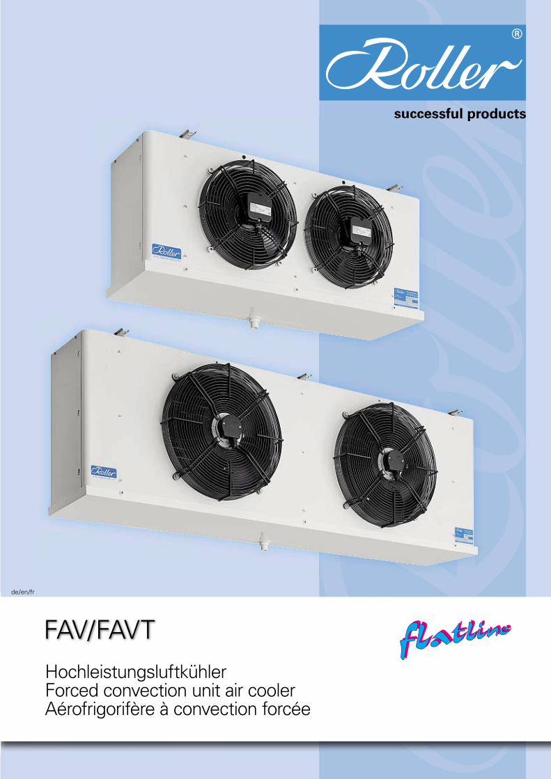
FAV/FAVT
de/en/fr
HochleistungsluftkühlerForced convection unit air coolerAérofrigorifère à convection forcée
ffllaattlliinneeffllaattlliinnee

2
ffllaattlliinneeffllaattlliinneeFAV/FAVT
Einsatzbereich:• Für R-Sicherheitskältemittel.• Für Kühl- und Tiefkühlräume mit normaler Luftfeuchtigkeit (z. B. verpackte Ware in Supermärkten).• Temperaturbereich:
FAV: > 0 °C,FAVT: > –30 °C.
Besondere Merkmale:Hochleistungswärmeaustauscher niedriger Bauhöhe mit geringem Innenvolumen.Montage der Schutzgitter mit Schalldämpfungselementen.Befestigungslöcher für Abtau-Sicherheitsthermostat (Zubehör).
Flache Aufhängeschiene aus CrNi-Stahl.Heizstäbe auf Klemmdose ver-drahtet.
Application range:• For safety refrigerants type R.• For cold storage and low tempe-rature rooms with normal humidi-ty (f. ex. packaged products in supermarkets).• Temperature range:
FAV: > 0 °C,FAVT: > –30 °C.
Special features:High effi ciency heat exchanger low at height with small interior volume.Fan guards mounted with sound absorbing elements.Mounting holes for defrost safety thermostat (accessory).
Flat stainless steel mounting rail.Heaters wired to terminal box.
Domaine d’utilisation:• Pour des fl uides frigorigènes de sécurité du type R.• Pour chambres froides et chambres de congélation à humidité normale (p. ex. produits emballés dans des supermarchés).• Domaine de température:
FAV: > 0 °C,FAVT: > –30 °C.
Caractéristiques particulières:Echangeur de chaleur de grand rendement plat avec un volume intérieur bas.Montage des grilles de protection avec des éléments d’insonorations.Trous de fi xation pour le thermostat de sécurité de dégivrage (accessoire).Barre de montage: acier spécial.Chauffage dégivrage raccorde à boîte de raccordement.
FAVT 622
FAVT 612
FAVT 601
3
ffllaattlliinneeffllaattlliinneeFAV/FAVT
ZubehörAccessoriesAccessoires
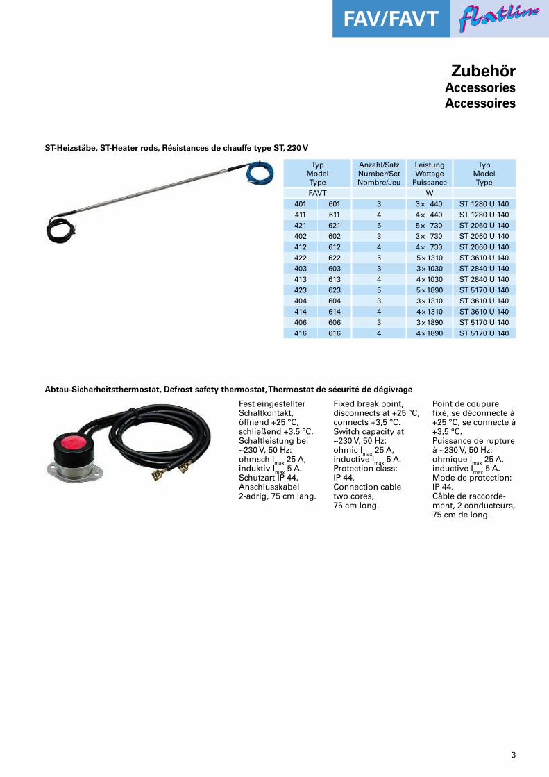
ST-Heizstäbe, ST-Heater rods, Résistances de chauffe type ST, 230 V
TypModelType
Anzahl/SatzNumber/SetNombre/Jeu
LeistungWattage
Puissance
TypModelType
FAVT W401 601 3 3 × 440 ST 1280 U 140411 611 4 4 × 440 ST 1280 U 140421 621 5 5 × 730 ST 2060 U 140402 602 3 3 × 730 ST 2060 U 140412 612 4 4 × 730 ST 2060 U 140422 622 5 5 × 1310 ST 3610 U 140403 603 3 3 × 1030 ST 2840 U 140413 613 4 4 × 1030 ST 2840 U 140423 623 5 5 × 1890 ST 5170 U 140404 604 3 3 × 1310 ST 3610 U 140414 614 4 4 × 1310 ST 3610 U 140406 606 3 3 × 1890 ST 5170 U 140416 616 4 4 × 1890 ST 5170 U 140
Abtau-Sicherheitsthermostat, Defrost safety thermostat, Thermostat de sécurité de dégivrage
Fest eingestellter Schaltkontakt,öffnend +25 °C, schließend +3,5 °C.Schaltleistung bei ~230 V, 50 Hz:ohmsch Imax 25 A,induktiv Imax 5 A.Schutzart IP 44. Anschlusskabel2-adrig, 75 cm lang.
Fixed break point, disconnects at +25 °C, connects +3,5 °C.Switch capacity at ~230 V, 50 Hz:ohmic Imax 25 A,inductive Imax 5 A.Protection class:IP 44. Connection cabletwo cores, 75 cm long.
Point de coupurefi xé, se déconnecte à +25 °C, se connecte à +3,5 °C.Puissance de rupture à ~230 V, 50 Hz:ohmique Imax 25 A,inductive Imax 5 A.Mode de protection: IP 44.Câble de raccorde-ment, 2 conducteurs, 75 cm de long.
4
ffllaattlliinneeffllaattlliinneeFAV/FAVT
G+20
44
F
35D
375 min. G
322
Ø12
=
A
1170 =
1170**
A
= =
A
=
A
=
fh27
0905
a.dw
g
==
A
EC
B
C
C
B
C
C*
B
C*E*
C
B
C
B
R3/4"
R3/4"
R3/4"
R3/4" *
R3/4"
R3/4"
R3/4" **
FAV/T .22
R3/4" **
FAV/T .14
==
* FHV/T .03/ .13** FHV/T .23
88
88
8
M
M
M
M
M
fh27
0905
a.d
wg
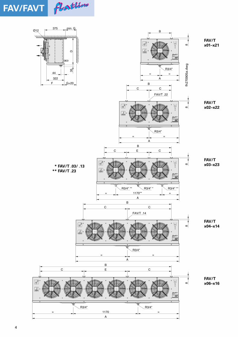
* FAV/T .03/ .13** FAV/T .23
FAV/Tx01–x21
FAV/Tx02–x22
FAV/Tx03–x23
FAV/Tx04–x14
FAV/Tx06–x16
5
ffllaattlliinneeffllaattlliinneeFAV/FAVT
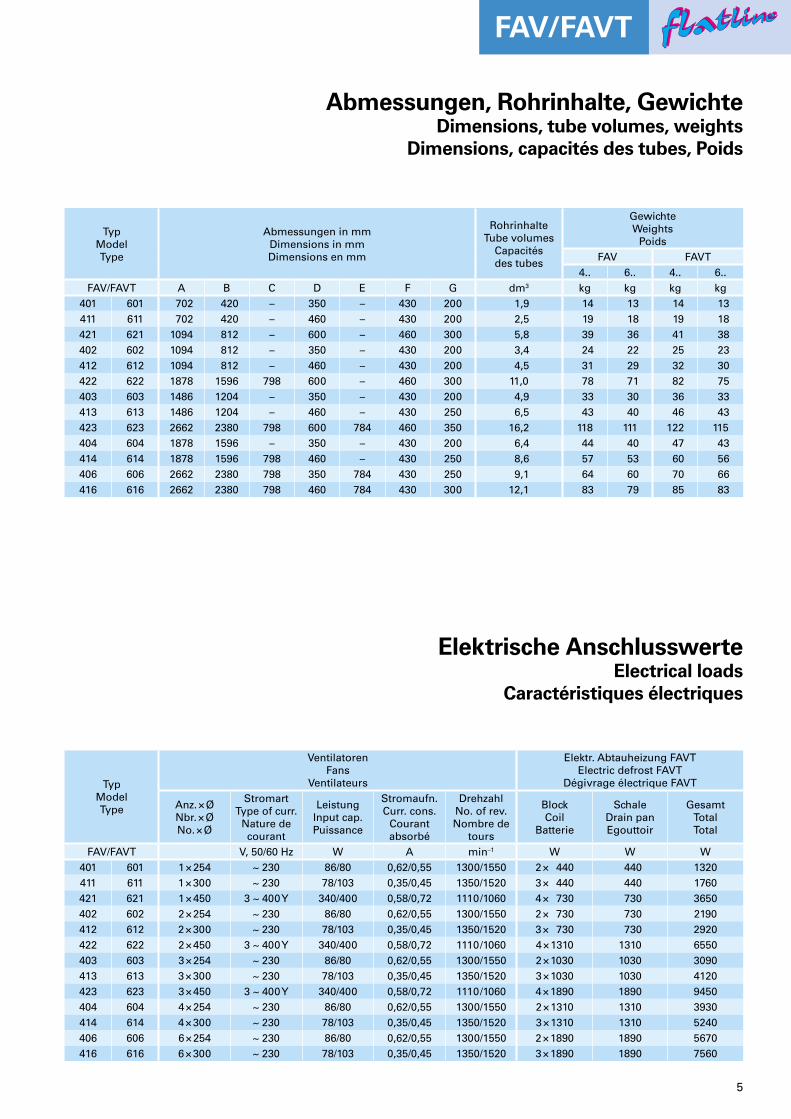
Abmessungen, Rohrinhalte, GewichteDimensions, tube volumes, weights
Dimensions, capacités des tubes, Poids
Elektrische AnschlusswerteElectrical loads
Caractéristiques électriques
TypModelType
Abmessungen in mmDimensions in mmDimensions en mm
RohrinhalteTube volumes
Capacitésdes tubes
GewichteWeights
PoidsFAV FAVT
4.. 6.. 4.. 6..FAV/FAVT A B C D E F G dm3 kg kg kg kg
401 601 702 420 – 350 – 430 200 1,9 14 13 14 13411 611 702 420 – 460 – 430 200 2,5 19 18 19 18421 621 1094 812 – 600 – 460 300 5,8 39 36 41 38402 602 1094 812 – 350 – 430 200 3,4 24 22 25 23412 612 1094 812 – 460 – 430 200 4,5 31 29 32 30422 622 1878 1596 798 600 – 460 300 11,0 78 71 82 75403 603 1486 1204 – 350 – 430 200 4,9 33 30 36 33413 613 1486 1204 – 460 – 430 250 6,5 43 40 46 43423 623 2662 2380 798 600 784 460 350 16,2 118 111 122 115404 604 1878 1596 – 350 – 430 200 6,4 44 40 47 43414 614 1878 1596 798 460 – 430 250 8,6 57 53 60 56406 606 2662 2380 798 350 784 430 250 9,1 64 60 70 66416 616 2662 2380 798 460 784 430 300 12,1 83 79 85 83
TypModelType
VentilatorenFans
Ventilateurs
Elektr. Abtauheizung FAVTElectric defrost FAVT
Dégivrage électrique FAVT
Anz. × ØNbr. × ØNo. × Ø
StromartType of curr.
Nature decourant
LeistungInput cap.Puissance
Stromaufn.Curr. cons.
Courantabsorbé
DrehzahlNo. of rev.Nombre de
tours
BlockCoil
Batterie
SchaleDrain panEgouttoir
GesamtTotalTotal
FAV/FAVT V, 50/60 Hz W A min–1 W W W401 601 1 × 254 ~ 230 86/80 0,62/0,55 1300/1550 2 × 440 440 1320411 611 1 × 300 ~ 230 78/103 0,35/0,45 1350/1520 3 × 440 440 1760421 621 1 × 450 3 ~ 400 Y 340/400 0,58/0,72 1110/1060 4 × 730 730 3650402 602 2 × 254 ~ 230 86/80 0,62/0,55 1300/1550 2 × 730 730 2190412 612 2 × 300 ~ 230 78/103 0,35/0,45 1350/1520 3 × 730 730 2920422 622 2 × 450 3 ~ 400 Y 340/400 0,58/0,72 1110/1060 4 × 1310 1310 6550403 603 3 × 254 ~ 230 86/80 0,62/0,55 1300/1550 2 × 1030 1030 3090413 613 3 × 300 ~ 230 78/103 0,35/0,45 1350/1520 3 × 1030 1030 4120423 623 3 × 450 3 ~ 400 Y 340/400 0,58/0,72 1110/1060 4 × 1890 1890 9450404 604 4 × 254 ~ 230 86/80 0,62/0,55 1300/1550 2 × 1310 1310 3930414 614 4 × 300 ~ 230 78/103 0,35/0,45 1350/1520 3 × 1310 1310 5240406 606 6 × 254 ~ 230 86/80 0,62/0,55 1300/1550 2 × 1890 1890 5670416 616 6 × 300 ~ 230 78/103 0,35/0,45 1350/1520 3 × 1890 1890 7560
6
ffllaattlliinneeffllaattlliinneeFAV/FAVT
* Mehrfacheinspritzung mit Schraderventil am Austritt* Multiple injection with Schrader valve at the outlet* Inyección múltiple avec la soupape en sortie
** Mittl. Schalldruckpegel in 1 m Abstand im Freifeld (halbkugelförmige Schallausbreitung)** Mean sound pressure level at a distance of 1 m in semi-reverberant fi eld** Pression sonore moyenne à une distance de 1 m en champ semi-réverbérant
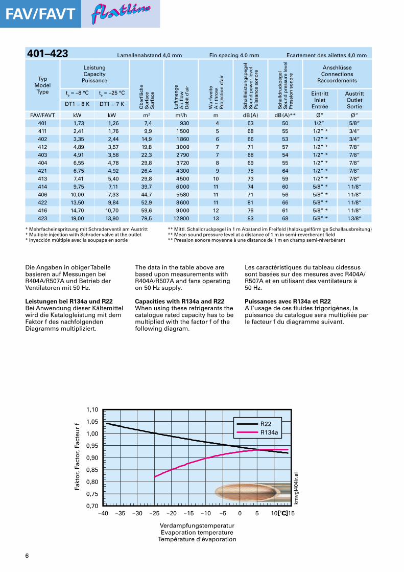
401–423 Lamellenabstand 4,0 mm Fin spacing 4.0 mm Ecartement des ailettes 4,0 mm
TypModelType
LeistungCapacity
Puissance
Ob
erfl
äch
eS
urf
ace
Su
rfac
e
Luft
men
ge
Air
fl o
wD
ébit
d’a
ir
Wu
rfw
eite
Air
th
row
Pro
ject
ion
d’a
ir
Sch
allle
istu
ng
speg
elS
ou
nd
po
wer
leve
lPu
issa
nce
so
no
re
Sch
alld
ruck
peg
elS
ou
nd
pre
ssu
re le
vel
Pres
sio
n s
on
ore
AnschlüsseConnections
Raccordements
te = –8 °C te = –25 °C EintrittInlet
Entrée
AustrittOutletSortieDT1 = 8 K DT1 = 7 K
FAV/FAVT kW kW m2 m3/h m dB (A) dB (A)** Ø“ Ø“401 1,73 1,26 7,4 930 4 63 50 1/2“ 5/8“411 2,41 1,76 9,9 1 500 5 68 55 1/2“ * 3/4“402 3,35 2,44 14,9 1 860 6 66 53 1/2“ * 3/4“412 4,89 3,57 19,8 3 000 7 71 57 1/2“ * 7/8“403 4,91 3,58 22,3 2 790 7 68 54 1/2“ * 7/8“404 6,55 4,78 29,8 3 720 8 69 55 1/2“ * 7/8“421 6,75 4,92 26,4 4 300 9 78 64 1/2“ * 7/8“413 7,41 5,40 29,8 4 500 10 73 59 1/2“ * 7/8“414 9,75 7,11 39,7 6 000 11 74 60 5/8“ * 1 1/8“406 10,00 7,33 44,7 5 580 11 71 56 5/8“ * 1 1/8“422 13,50 9,84 52,9 8 600 11 81 66 5/8“ * 1 1/8“416 14,70 10,70 59,6 9 000 12 76 61 5/8“ * 1 1/8“423 19,00 13,90 79,5 12 900 13 83 68 5/8“ * 1 3/8“
Die Angaben in obiger Tabellebasieren auf Messungen bei R404A/R507A und Betrieb der Ventilatoren mit 50 Hz.
Leistungen bei R134a und R22Bei Anwendung dieser Kältemittel wird die Katalogleistung mit dem Faktor f des nachfolgenden Diagramms multipliziert.
The data in the table above are based upon measurements with R404A/R507A and fans operating on 50 Hz supply.
Capacities with R134a and R22When using these refrigerants the catalogue rated capacity has to be multiplied with the factor f of the following diagram.
Les caractéristiques du tableau cidessus sont basées sur des mesures avec R404A/R507A et en utilisant des ventilateurs à 50 Hz.
Puissances avec R134a et R22A l’usage de ces fl uides frigorigènes, la puissance du catalogue sera multipliée par le facteur f du diagramme suivant.
Fakt
or,
Fac
tor,
Fac
teu
r f
VerdampfungstemperaturEvaporation temperature
Température d‘évaporation
7
ffllaattlliinneeffllaattlliinneeFAV/FAVT
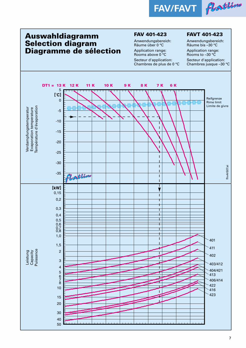
AuswahldiagrammSelection diagramDiagramme de sélection
FAV 401-423 FAVT 401-423Anwendungsbereich: Räume über 0 °CApplication range: Rooms above 0 °CSecteur d'application: Chambres de plus de 0 °C
Anwendungsbereich: Räume bis –30 °CApplication range: Rooms to –30 °CSecteur d'application: Chambres jusque –30 °C
fhv4
r507
.ai
ReifgrenzeRime limitLimite de givre
401
411
402
403/412
404/421413406/414422
423
0,15
0,2
0,3
0,40,50,60,70,81,0
1,5
2
3
45678
10
15
20
30
4050
[kW]
Leis
tun
gC
apac
ity
Puis
san
ce
416
DT1 = 6 K13 K 10 K 9 K 8 K 7 K11 K12 K5
[˚C]0
-5
-10
-15
-20
-25
-30
-35
Verd
amp
fun
gst
emp
erat
ur
Eva
po
rati
on
tem
per
atu
reTe
mp
érat
ure
d'é
vap
ora
tio
n

8
ffllaattlliinneeffllaattlliinneeFAV/FAVT
* Mehrfacheinspritzung mit Schraderventil am Austritt* Multiple injection with Schrader valve at the outlet* Inyección múltiple avec la soupape en sortie
** Mittl. Schalldruckpegel in 1 m Abstand im Freifeld (halbkugelförmige Schallausbreitung)** Mean sound pressure level at a distance of 1 m in semi-reverberant fi eld** Pression sonore moyenne à une distance de 1 m en champ semi-réverbérant
601–623 Lamellenabstand 6,0 mm Fin spacing 6.0 mm Ecartement des ailettes 6,0 mm
TypModelType
LeistungCapacity
Puissance
Ob
erfl
äch
eS
urf
ace
Su
rfac
e
Luft
men
ge
Air
fl o
wD
ébit
d’a
ir
Wu
rfw
eite
Air
th
row
Pro
ject
ion
d’a
ir
Sch
allle
istu
ng
speg
elS
ou
nd
po
wer
leve
lPu
issa
nce
so
no
re
Sch
alld
ruck
peg
elS
ou
nd
pre
ssu
re le
vel
Pres
sio
n s
on
ore
AnschlüsseConnections
Raccordements
te = –8 °C te = –25 °C EintrittInlet
Entrée
AustrittOutletSortieDT1 = 8 K DT1 = 7 K
FAV/FAVT kW kW m2 m3/h m dB (A) dB (A)** Ø“ Ø“601 1,46 1,06 5,2 980 4 63 50 1/2“ 5/8“611 2,03 1,48 6,9 1 560 5 68 55 1/2“ * 3/4“602 2,81 2,05 10,3 1 960 6 66 53 1/2“ * 3/4“612 4,11 3,00 13,8 3 120 7 71 57 1/2“ * 7/8“603 4,13 3,01 15,5 2 940 7 68 54 1/2“ * 7/8“604 5,51 4,02 20,7 3 920 8 69 55 1/2“ * 7/8“621 5,67 4,13 18,4 4 400 9 78 64 1/2“ * 7/8“613 6,23 4,54 20,7 4 680 10 73 59 1/2“ * 7/8“614 8,19 5,98 27,6 6 240 11 74 60 5/8“ * 1 1/8“606 8,44 6,16 31,0 5 880 11 71 56 5/8“ * 1 1/8“622 11,30 8,27 36,8 8 800 11 81 66 5/8“ * 1 1/8“616 12,30 8,99 41,4 9 360 12 76 61 5/8“ * 1 1/8“623 16,00 11,70 55,2 13 200 13 83 68 5/8“ * 1 3/8“
Die Angaben in obiger Tabellebasieren auf Messungen bei R404A/R507A und Betrieb der Ventilatoren mit 50 Hz.
Leistungen bei R134a und R22Bei Anwendung dieser Kältemittel wird die Katalogleistung mit dem Faktor f des nachfolgenden Diagramms multipliziert.
The data in the table above are based upon measurements with R404A/R507A and fans operating on 50 Hz supply.
Capacities with R134a and R22When using these refrigerants the catalogue rated capacity has to be multiplied with the factor f of the following diagram.
Les caractéristiques du tableau cidessus sont basées sur des mesures avec R404A/R507A et en utilisant des ventilateurs à 50 Hz.
Puissances avec R134a et R22A l’usage de ces fl uides frigorigènes, la puissance du catalogue sera multipliée par le facteur f du diagramme suivant.
Fakt
or,
Fac
tor,
Fac
teu
r f
VerdampfungstemperaturEvaporation temperature
Température d‘évaporation
9
ffllaattlliinneeffllaattlliinneeFAV/FAVT
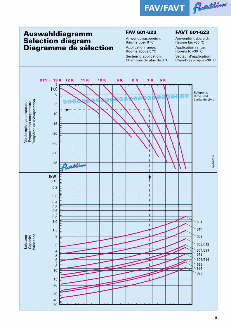
AuswahldiagrammSelection diagramDiagramme de sélection
FAV 601-623 FAVT 601-623Anwendungsbereich: Räume über 0 °CApplication range: Rooms above 0 °CSecteur d'application: Chambres de plus de 0 °C
Anwendungsbereich: Räume bis –30 °CApplication range: Rooms to –30 °CSecteur d'application: Chambres jusque –30 °C
fhv6
r507
.ai
ReifgrenzeRime limitLimite de givre
601
611
602
603/612
604/621613606/614622
623
0,15
0,2
0,3
0,40,50,60,70,81,0
1,5
2
3
45678
10
15
20
30
4050
[kW]
Leis
tun
gC
apac
ity
Puis
san
ce
616
DT1 = 6 K13 K 10 K 9 K 8 K 7 K11 K12 K5
[˚C]0
-5
-10
-15
-20
-25
-30
-35
Verd
amp
fun
gst
emp
erat
ur
Eva
po
rati
on
tem
per
atu
reTe
mp
érat
ure
d'é
vap
ora
tio
n
10
ffllaattlliinneeffllaattlliinneeFAV/FAVT
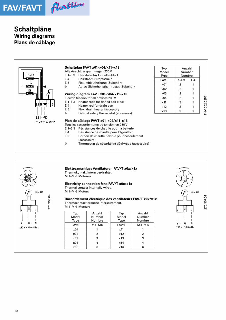
SchaltpläneWiring diagramsPlans de câblage
270.
907.
04
270.
903.
04
Elektroanschluss Ventilatoren FAV/T x0x/x1xThermokontakt intern verdrahtet.M 1–M 6 Motoren
Electricity connection fans FAV/T x0x/x1xThermal contact internally wired.M 1–M 6 Motors
Raccordement électrique des ventilateurs FAV/T x0x/x1xThermocontact branché intérieurement.M 1–M 6 Moteurs
TypModelType
AnzahlNumberNombre
FAV/T M 1–M 6x01 1x02 2x03 3x04 4x06 6
TypModelType
AnzahlNumberNombre
FAV/T M 1–M 6x11 1x12 2x13 3x14 4x16 6
Schaltplan FAVT x01–x04/x11–x13Alle Anschlussspannungen 230 VE 1–E 3 Heizstäbe für LamellenblockE 4 Heizstab für TropfschaleE 5 Flex. Ablaufheizung (Zubehör)! Abtau-Sicherheitsthermostat (Zubehör)
Wiring diagram FAVT x01–x04/x11–x13Electric tension for all devices 230 VE 1–E 3 Heater rods for fi nned coil blockE 4 Heater rod for drain panE 5 Flex. drain heater (accessory)! Defrost safety thermostat (accessory)
Plan de câblage FAVT x01–x04/x11–x13Tous les raccordements de tension en 230 VE 1–E 3 Résistances de chauffe pour la batterieE 4 Résistance de chauffe pour l’égouttoirE 5 Cordon de chauffe fl exible pour l’écoulement (accessoire)! Thermostat de sécurité de dégivrage (accessoire)
TypModelType
AnzahlNumberNombre
FAVT E 1–E 3 E 4x01 2 1x02 2 1x03 2 1x04 2 1x11 3 1x12 3 1x13 3 1
FHV
002
.025
7
11
ffllaattlliinneeffllaattlliinneeFAV/FAVT
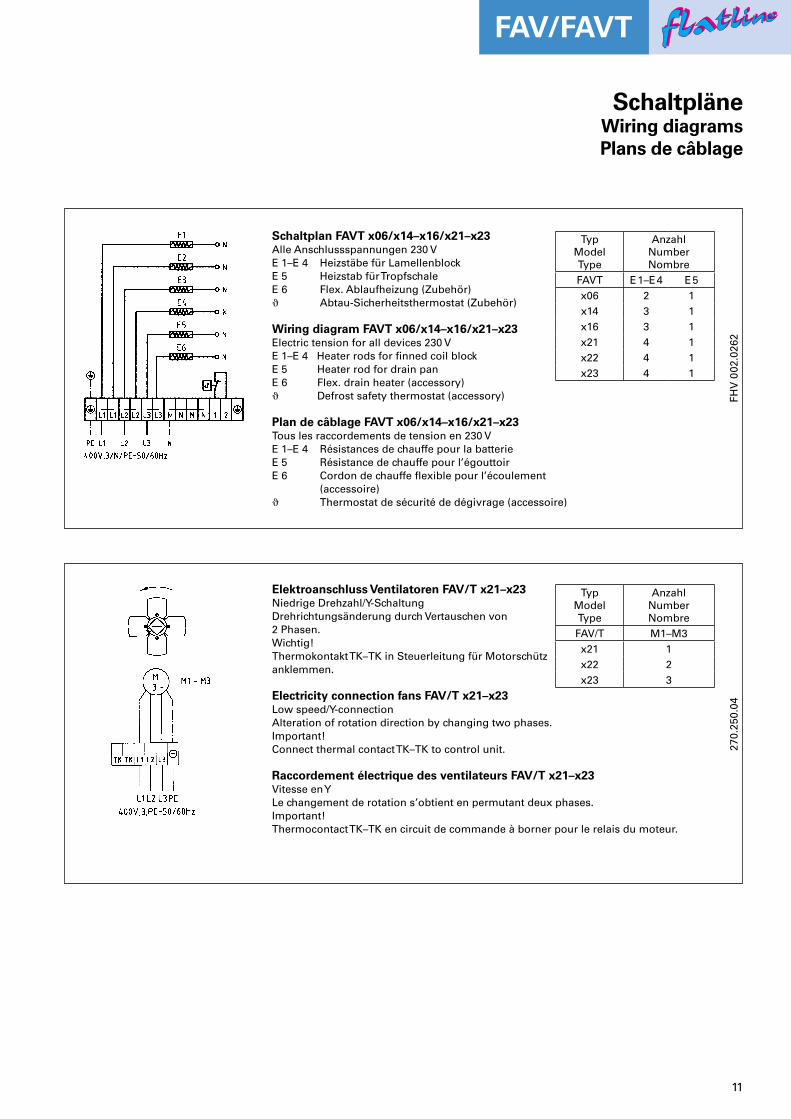
Schaltplan FAVT x06/x14–x16/x21–x23Alle Anschlussspannungen 230 VE 1–E 4 Heizstäbe für LamellenblockE 5 Heizstab für TropfschaleE 6 Flex. Ablaufheizung (Zubehör)! Abtau-Sicherheitsthermostat (Zubehör)
Wiring diagram FAVT x06/x14–x16/x21–x23Electric tension for all devices 230 VE 1–E 4 Heater rods for fi nned coil blockE 5 Heater rod for drain panE 6 Flex. drain heater (accessory)! Defrost safety thermostat (accessory)
Plan de câblage FAVT x06/x14–x16/x21–x23Tous les raccordements de tension en 230 VE 1–E 4 Résistances de chauffe pour la batterieE 5 Résistance de chauffe pour l’égouttoirE 6 Cordon de chauffe fl exible pour l’écoulement (accessoire)! Thermostat de sécurité de dégivrage (accessoire)
FHV
002
.026
2
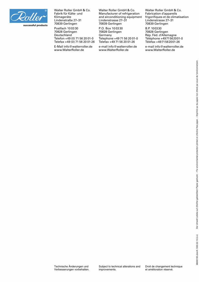
Elektroanschluss Ventilatoren FAV/T x21–x23Niedrige Drehzahl/Y-SchaltungDrehrichtungsänderung durch Vertauschen von2 Phasen. Wichtig!Thermokontakt TK–TK in Steuerleitung für Motorschützanklemmen.
Electricity connection fans FAV/T x21–x23Low speed/Y-connectionAlteration of rotation direction by changing two phases.Important!Connect thermal contact TK–TK to control unit.
Raccordement électrique des ventilateurs FAV/T x21–x23 Vitesse en YLe changement de rotation s’obtient en permutant deux phases. Important!Thermocontact TK–TK en circuit de commande à borner pour le relais du moteur.
270.
250.
04
SchaltpläneWiring diagramsPlans de câblage
TypModelType
AnzahlNumberNombre
FAVT E 1–E 4 E 5x06 2 1x14 3 1x16 3 1x21 4 1x22 4 1x23 4 1
TypModelType
AnzahlNumberNombre
FAV/T M1–M3x21 1x22 2x23 3
Technische Änderungen undVerbesserungen vorbehalten.
Subject to technical alterations andimprovements.
Droit de changement techniqueet amélioration réservé.
Der
Um
wel
t zul
iebe
auf
chl
orfr
ei g
eble
icht
em P
apie
r ge
druc
kt. –
For
env
ironm
enta
l pro
tect
ion
prin
ted
on c
hlor
ine
free
pap
er. –
Impr
imé
sur
du p
apie
r no
n ch
loré
par
sou
ci d
e l’e
nviro
nnem
ent.
8800
0195
.d/e
n/fr
.100
0.02
.13.
U+
U
Walter Roller GmbH & Co.Fabrik für Kälte- undKlimageräteLindenstraße 27–3170839 Gerlingen
Postfach 10 03 3070828 GerlingenDeutschlandTelefon +49 (0) 71 56 20 01-0Telefax +49 (0) 71 56 20 01-26
E-Mail [email protected]
Walter Roller GmbH & Co.Manufacturer of refrigeration and airconditioning equipmentLindenstrasse 27–3170839 Gerlingen
P.O. Box 10 03 3070828 GerlingenGermanyTelephone +49 71 56 20 01-0Telefax +49 71 56 20 01-26
e-mail [email protected]
Walter Roller GmbH & Co.Fabrication d’appareils frigorifi ques et de climatisationLindenstrasse 27–3170839 Gerlingen
B.P. 10 03 3070828 GerlingenRép. Féd. d’AllemagneTéléphone +49 71 56 20 01-0Téléfax +49 71 56 20 01-26
e-mail [email protected]