dedstf hvdc technology siemens pjm for issue
TRANSCRIPT

siemens.com/energyRestricted © Siemens 2017 All rights reserved.
HVDC Technology

Restricted © Siemens 2017 All rights reserved.
HVDC - High Voltage Direct Current
µ Why HVDC?
µTechnology – Classic & PLUS

Restricted © Siemens 2017 All rights reserved.
DCSystem
System 1 System 2
ACAC
HVDC is a unique Solution for:
Why HVDC?HVDC – Many Benefits
ƒ Long Overhead Lines with highTransmission Capacity and limitedRight-of-Way
ƒ Long Cable Transmissions
ƒ Asynchronous Interconnections
ƒ New Links in Grids where Short-CircuitCurrents are at upper Limits
ƒ Fast Control of Power Flow
ƒ Sharing of Spinning Reserve
ƒ Supply of Peak Power

Restricted © Siemens 2017 All rights reserved.
DC LineSystem A System B
ACAC
Long Distance
Back-to-Back
System A System B
ACAC
DC Cable
DC Cable
AC ACSystem BSystem A
Basics of HVDCHVDC Applications
Restricted © Siemens 2017 All rights reserved.
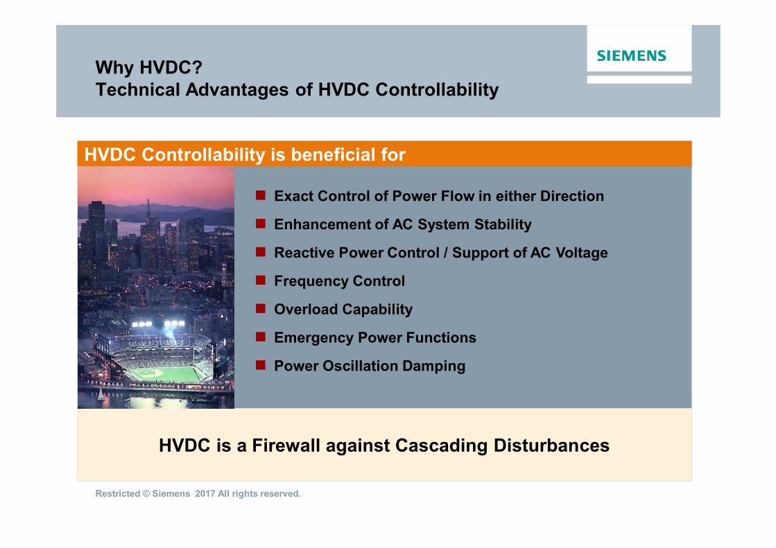
µ Exact Control of Power Flow in either Direction
µ Enhancement of AC System Stability
µ Reactive Power Control / Support of AC Voltage
µ Frequency Control
µ Overload Capability
µ Emergency Power Functions
µ Power Oscillation Damping
HVDC is a Firewall against Cascading Disturbances
HVDC Controllability is beneficial for
Why HVDC?Technical Advantages of HVDC Controllability

Restricted © Siemens 2017 All rights reserved.
HVDC Long Distance Transmission Systems
Bipolar
TransmissionLineTerminal A Terminal B
Pole 1
Pole 2
TransmissionLine
Terminal A Terminal B
Monopolar
Restricted © Siemens 2017 All rights reserved.
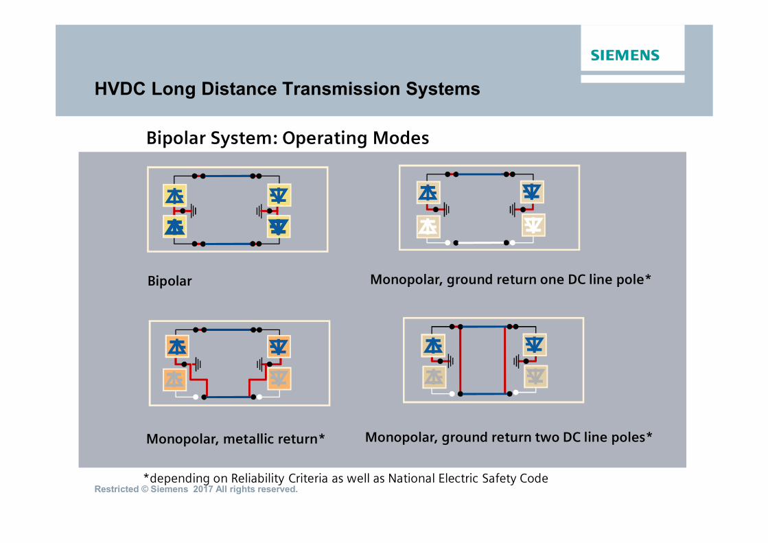
HVDC Long Distance Transmission Systems
Bipolar System: Operating Modes
Monopolar, metallic return*
Bipolar Monopolar, ground return one DC line pole*
Monopolar, ground return two DC line poles*
*depending on Reliability Criteria as well as National Electric Safety Code

Restricted © Siemens AG 2014 All rights reserved.
DC Cable
Terminal A Terminal B
µ Symmetrical Monopole
HVDC Long Distance Transmission Systems
OHL / Cable
Terminal A Terminal BOHL / Cable
Metallic Return
Ground/SeaReturn
µ Bipole
Hybrid Tower
AC DC
DC Tower
July 2014 E T TS 2 HVDCPage 8
Restricted © Siemens 2017 All rights reserved.
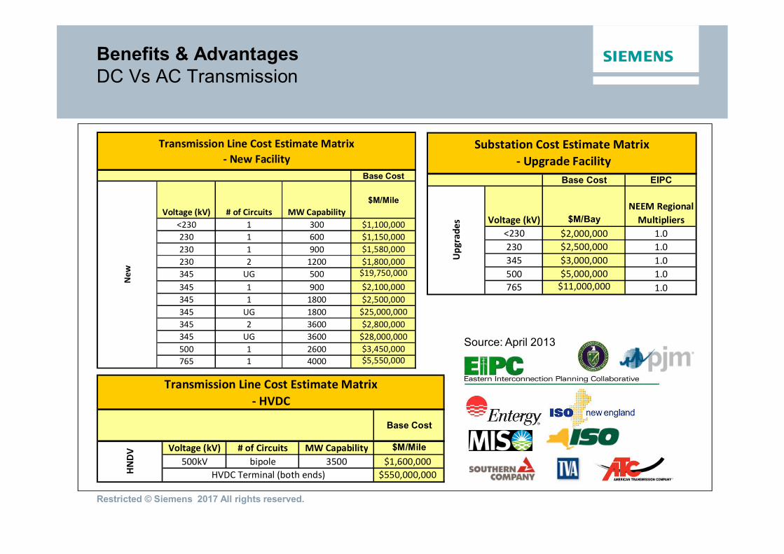
Benefits & AdvantagesDC Vs AC Transmission
Transmission Line Cost Estimate Matrix- New Facility
Base Cost
Voltage (kV) # of Circuits MW Capability$M/Mile
<230 1 300 $1,100,000230 1 600 $1,150,000230 1 900 $1,580,000230 2 1200 $1,800,000345 UG 500 $19,750,000345 1 900 $2,100,000345 1 1800 $2,500,000345 UG 1800 $25,000,000345 2 3600 $2,800,000345 UG 3600 $28,000,000500 1 2600 $3,450,000765 1 4000 $5,550,000
New
Base Cost EIPC
Voltage (kV) $M/BayNEEM Regional
Multipliers<230 $2,000,000 1.0230 $2,500,000 1.0345 $3,000,000 1.0500 $5,000,000 1.0765 $11,000,000 1.0
Substation Cost Estimate Matrix - Upgrade Facility
Upg
rade
s
Transmission Line Cost Estimate Matrix- HVDC
Base Cost
Voltage (kV) # of Circuits MW Capability $M/Mile500kV bipole 3500 $1,600,000
$550,000,000HVDC Terminal (both ends)HNDV
Source: April 2013

Restricted © Siemens 2017 All rights reserved.
Break-even Distance
Benefits & AdvantagesDC Vs AC Transmission – Break-even
Thousands of Dollars / MW
$0
$50
$100
$150
$200
$250
$300
$350
$400
$450
50 100 125 150 175 200 250 300 Miles
k$/M
W
HVDCAC 500AC 600AC 765
Break-even Point

Restricted © Siemens 2017 All rights reserved.
Benefits & AdvantagesDC Vs AC Transmission – Other advantages
ƒ Increasing AC transmissiondistances require Series andShunt reactive powerCompensation (SSC)
ƒ At similar voltage level, a DCline can transmit more thandouble the power at aroundhalf the losses compared toan AC line.
ƒ Comparison of Towers at thesame transmission capacityof 3000 MW for:ƒ a) 765kV AC Lineƒ b) 500kV DC Line
Reactive Power Transmission LossesRight of Way
Source: March 2013
Restricted © Siemens 2017 All rights reserved.
HVDC - High Voltage Direct Current
µ Why HVDC?
µTechnology – Classic & PLUS

Restricted © Siemens 2017 All rights reserved.
HVDC Classic HVDC VSC
Line-commutated Self-commutatedcurrent-sourced Converter voltage-sourced Converter
Thyristor with turn-on Capability Semiconductor Switches with turn-ononly and turn-off Capability, e.g. IGBTs
HVDC Classic – HVDC PLUS

Restricted © Siemens 2017 All rights reserved.
µ Id in one Direction only
µ Magnitude of P / Id is controlled bythe Converter DC Voltages Id = (Ud Rect – Ud Inv) / R
µ Direction of P is controlled changingthe Polarity of the DC Voltages (UdRect, Ud Inv)
Characteristics
DCSystem
System A System B
ACAC
Simplified Block Diagram
HVDC “Classic”Principle of HVDC
Ud Rect Ud Inv
Ud Line
Ud Rect.
P
Id R
Equivalent CircuitUd Line (Id*RLine)
Ud LInv

Restricted © Siemens 2017 All rights reserved.
HVDC Classic - Principles
HVDC Classic is generally the name used by all manufacturers but the technologymay be referred to as LCC or Thyristor
HVDC Classic the AC-DC conversion (and vice versa) is carried out by a thyristorarrangement known as a valve.
The thyristor valve needs a relatively strong system to support its operationhowever additional equipment such as SVC and Synchronous Condensers canprovide local system reinforcement to allow HVDC Classic to operate in “weak”systems.
HVDC Classic can generate significant harmonics on to the connecting system.
Each HVDC Classic installation requires, therefore, multiple filters to mitigate theharmonics which can require significant footprint at the converter station site.
HVDC Classic is available up to +/- 800kV with power transfer of up to 8GW(8,000MW)
Restricted © Siemens 2017 All rights reserved.
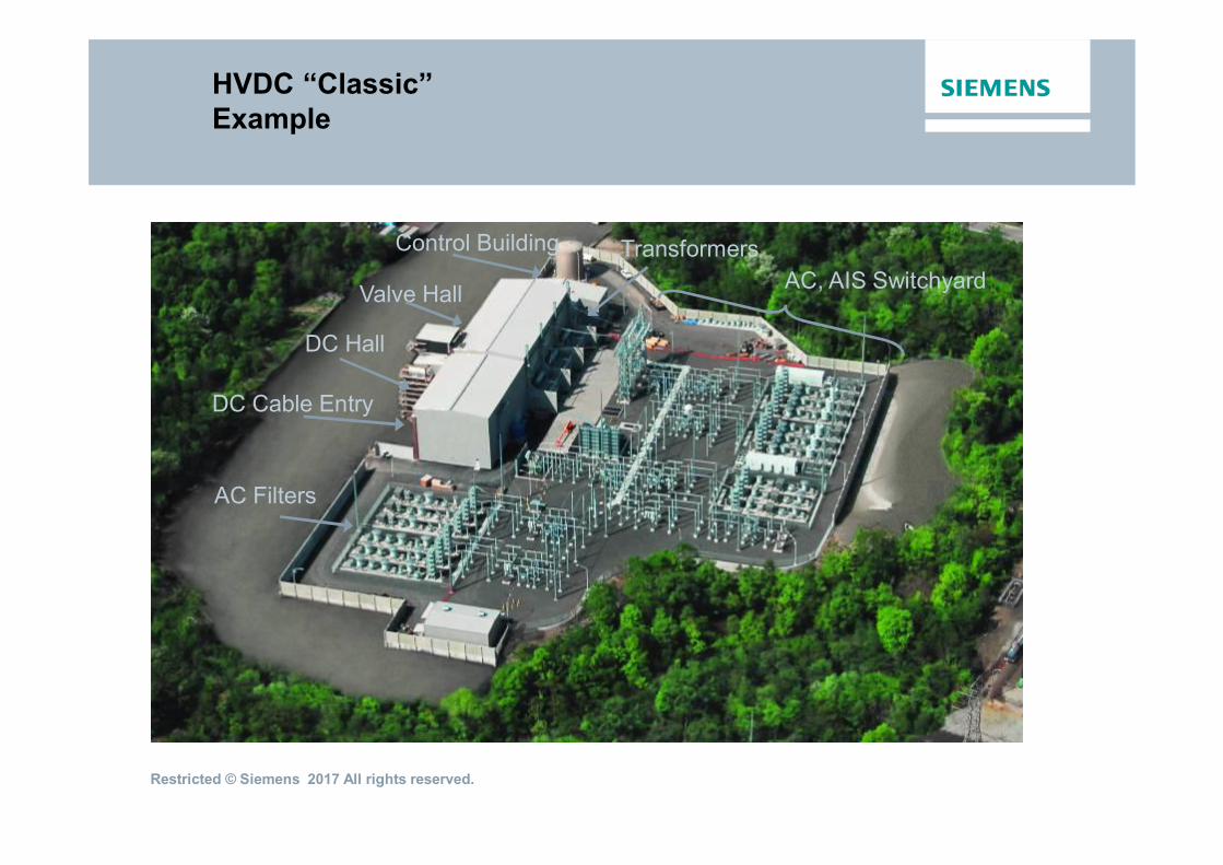
HVDC “Classic”Example
AC Filters
DC Hall
DC Cable Entry
Valve Hall AC, AIS SwitchyardTransformersControl Building

Restricted © Siemens 2017 All rights reserved.
AC Filters, Capacitor BanksReactive Power and AC Filtering
Power in p.u.
-200
-100
0
100
200
300
400
500
600
0 0,2 0,4 0,6 0,8 1 1,2 1,4
Q[MVAr]
Q filter
delta Q
Q rect.
-80
+80
HVDC StationAC Filters
1 2 3 4 5 6 7 8 9 10 11 13 23 25 35 37 47 49
current [%]100
1
0.1
0.01order of harmonic
10
Restricted © Siemens 2017 All rights reserved.
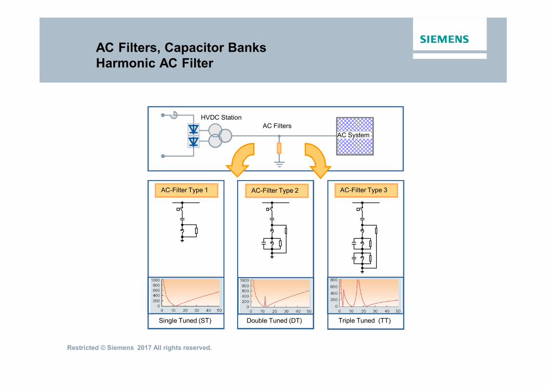
AC Filters, Capacitor BanksHarmonic AC Filter
AC-Filter Type 3
Triple Tuned (TT)
AC-Filter Type 1
Single Tuned (ST)
AC-Filter Type 2
Double Tuned (DT)
HVDC StationAC Filters
AC System

Restricted © Siemens 2017 All rights reserved.
Converter TransformersSingle Phase, 3 Winding
Siemens HVDC Converter Transformers - Outstanding Performance since 1977
400 MVA 1-ph / 3-w 354 MVA 1-ph / 3-w
Converter Transformer: Obtain the AC voltage needed for the required DC voltageObtain 12-pulse operation (star and delta connection)Allow for series connection of 6-pulse bridges

Restricted © Siemens 2017 All rights reserved.
Valve Hall

Restricted © Siemens 2017 All rights reserved.
µ 80 % less Electronic Components
µ Direct Laser Light-triggered Thyristor
µ Wafer-integrated Overvoltage Protection
µ Thyristor Blocking Voltage: 8 kV
µ Thyristor Wafers:
µ 4" for currents up to 2,200 A
µ 5" for currents up to 4,000 A
µ 6" for currents up to 4,500 A (ETT)
Thyristor Technology – Direct Light Triggered Thyristor LTT
High Reliability:
Key ComponentsThyristor

Restricted © Siemens 2017 All rights reserved.
Valve Design
Design of Thyristor Stack
Heatsinks 16 Thyristors Spring PackageValve Design: 5 x 16 = 80 Thyristors
Optimum usage of thyristor stack size
Thyristor Features:• Blocking Voltage > 8 kV• Direct Light Triggered (LTT)• Integrated overvoltage protection (BO)• 5“-LTT: T 2563 N 80 T S 34

Restricted © Siemens 2017 All rights reserved.
Modular Unit / Valve Sections
Restricted © Siemens 2017 All rights reserved.
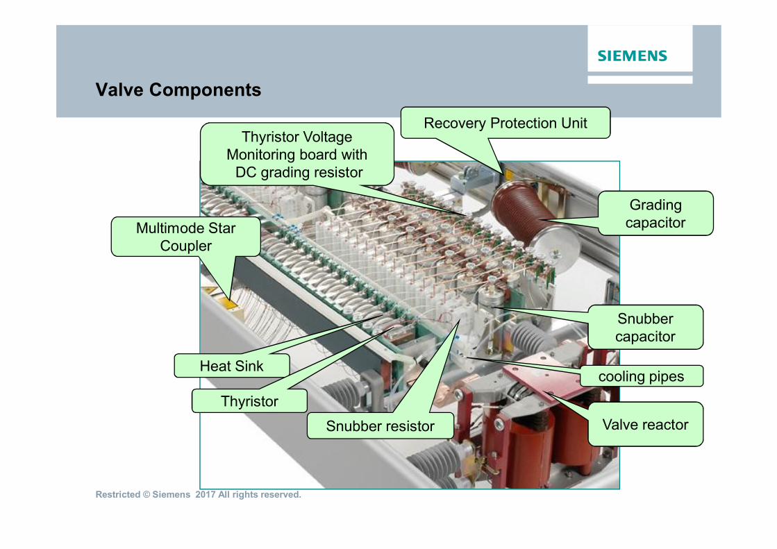
Valve Components
Heat Sink
Valve reactorSnubber resistor
cooling pipes
Snubbercapacitor
Thyristor VoltageMonitoring board with
DC grading resistor
Multimode StarCoupler
Gradingcapacitor
Recovery Protection Unit
Thyristor
Restricted © Siemens 2017 All rights reserved.
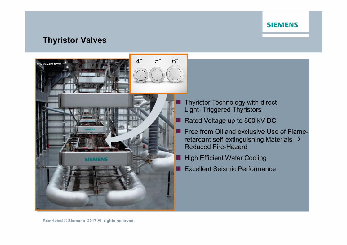
µ Thyristor Technology with directLight- Triggered Thyristors
µ Rated Voltage up to 800 kV DC
µ Free from Oil and exclusive Use of Flame-retardant self-extinguishing MaterialsReduced Fire-Hazard
µ High Efficient Water Cooling
µ Excellent Seismic Performance
Thyristor Valves
4“ 5“ 6“

Restricted © Siemens 2017 All rights reserved.
Air-Core Design
Smoothing Reactors and DCFilters
Oil immersed Design
270 mH
500 kV DC
3,000 A
150 mH
500 kV DC
1,800 A
µ Reduction of Current Ripple (on the DC Cable)
µ Limitation of DC Fault Currents
µ Protection of Valves against Transient Overcurrents
µ Prevention of Resonance in the DC Circuit
µ Prevention of intermittent Currents
Smoothing Reactor:

Restricted © Siemens 2017 All rights reserved.
800kV Converter Station
Shenzhen Converter Station
AC Filters, Capacitor Banks: Reactive power supplyFilter harmonic currents

Restricted © Siemens 2017 All rights reserved.
HVDC Classic HVDC VSC
Line-commutated Self-commutatedcurrent-sourced Converter voltage-sourced Converter
Thyristor with turn-on Capability Semiconductor Switches with turn-ononly and turn-off Capability, e.g. IGBTs
HVDC Classic – HVDC PLUS

Restricted © Siemens 2017 All rights reserved.
VSC HVDC - Principles
VSC HVDC is a generic name but most manufacturers try to use their brandname: Siemens – HVDC PLUS
In HVDC PLUS the AC-DC conversion (and vice versa) is carried out by an IGBT(Insulated Gate Bipolar Transistor) arrangement known as a power module.
HVDC PLUS works well with weak systems as it does not need any externalreferences to generate voltage or frequency. HVDC PLUS does not generate anyharmonics on to the connecting system and so does not need filters.
HVDC PLUS independently controls active and reactive power e.g. at each endthere is effectively a Statcom.
HVDC PLUS can support Blackstart (network restoration) and can be used with arange of underground or undersea cable technologies and overhead lines.
HVDC PLUS is currently available up to +/- 525kV with power transfer of up to2,000MW

Restricted © Siemens 2017 All rights reserved.
HVDC PLUSThe Evolution of HVDC PLUS and VSC Technology
Power Electronic DevicesGTO /IGCT IGBT in PP IGBT Module
Topology of VSCTwo-Level Three-Level Multilevel
Restricted © Siemens 2017 All rights reserved.
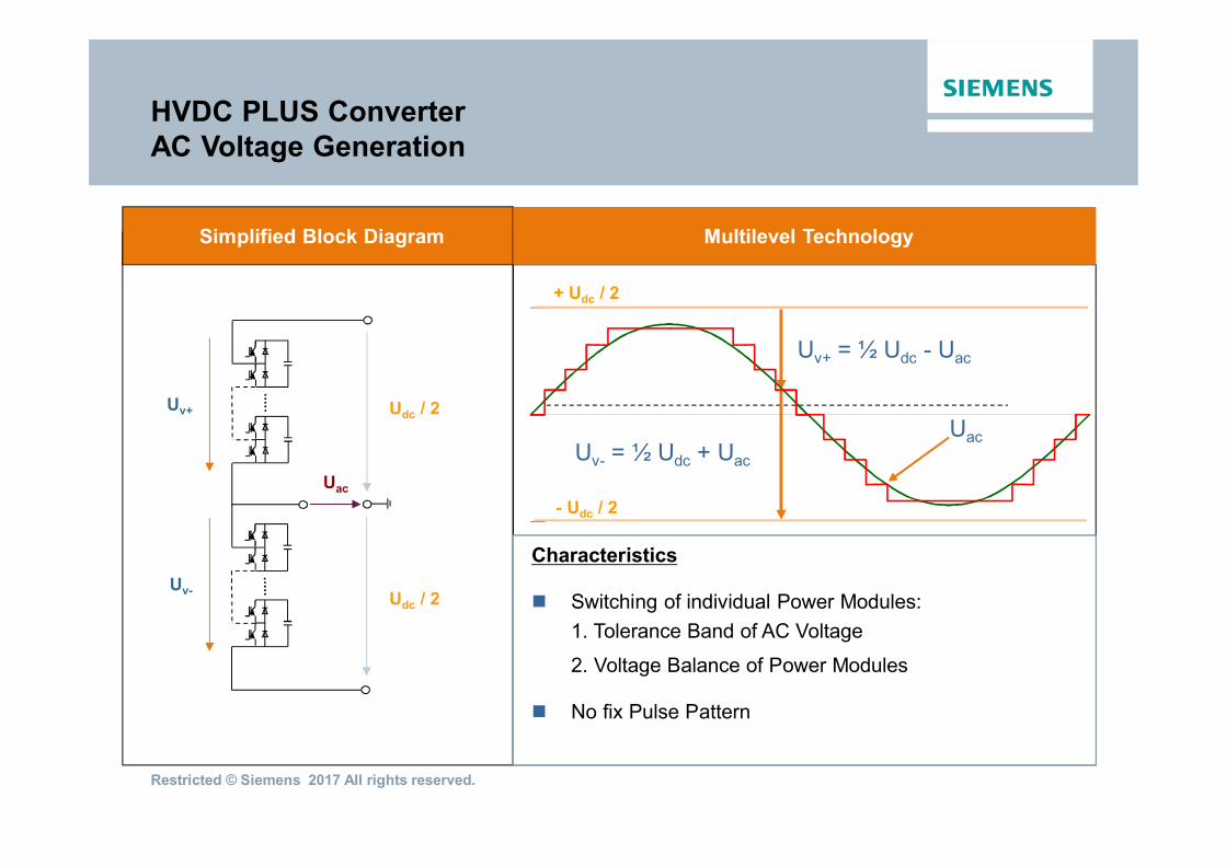
HVDC PLUS ConverterAC Voltage Generation
Simplified Block Diagram
Udc / 2
Uac
Udc / 2Uv+
Uv-
Multilevel Technology
Uv+ = ½ Udc - Uac
Uv- = ½ Udc + Uac
+ Udc / 2
- Udc / 2
Uac
Characteristics
µ Switching of individual Power Modules:1. Tolerance Band of AC Voltage
2. Voltage Balance of Power Modules
µ No fix Pulse Pattern
Restricted © Siemens 2017 All rights reserved.
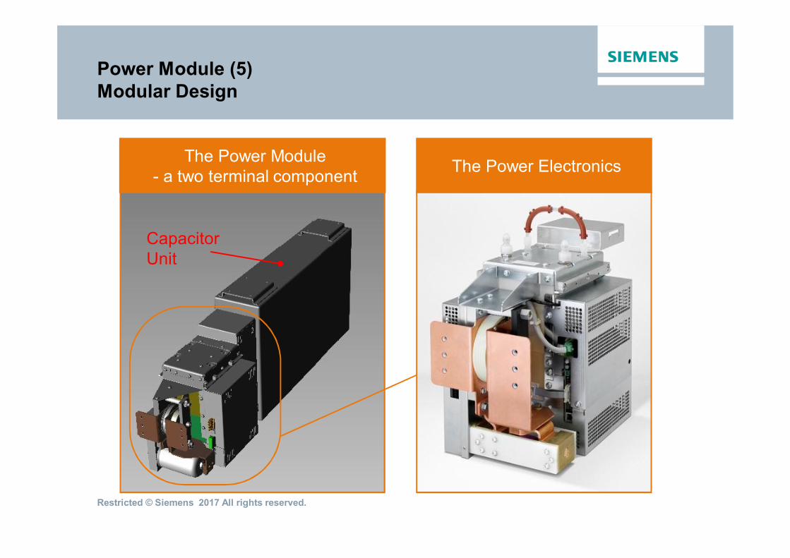
Power Module (5)Modular Design
The Power Module- a two terminal component
CapacitorUnit
The Power Electronics

Restricted © Siemens 2017 All rights reserved.
Power Module (5)Modular Converter Design
Double Tower with:µ 3 Floors (72 Power Modules)µ 4 Floors (96 Power Modules)
µ Defined internal Voltage Stressµ Compact Installation
Replacement ofsingle Power Modules
“6-Pack“Shipping unit ex-works

Restricted © Siemens 2017 All rights reserved.
Power ModuleHVDC PLUS – One Step ahead
µ Compact Design
µ Modular Design
µ Lower Space Requirements
µ Advanced VSC Technology
µ Maintenance friendly
Restricted © Siemens 2017 All rights reserved.
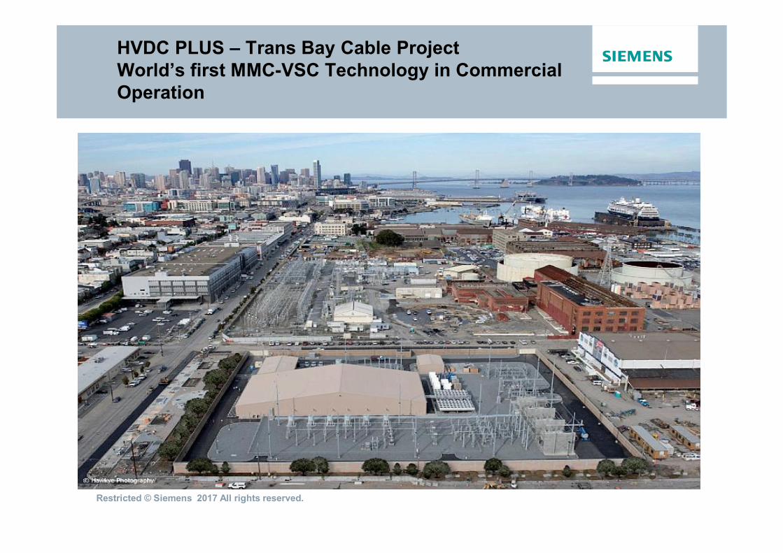
HVDC PLUS – Trans Bay Cable ProjectWorld’s first MMC-VSC Technology in CommercialOperation

Restricted © Siemens 2017 All rights reserved.
Trans Bay Cable ProjectValve Hall

Restricted © Siemens 2017 All rights reserved.
INELFE ProjectValve Hall

Restricted © Siemens 2017 All rights reserved.
PM Electronics
D1IGBT1
IGBT2 D2
Udc
0
uac
"on" "off"
µ Half Bridge Power ModuleThe Solution for CableTransmission w/o OHL
PM Electronics
D11 D21IGBT21
IGBT22
IGBT11
IGBT12D12 D22
D11 D21IGBT21
IGBT22
IGBT11
IGBT12D12 D22
D11 D21
IGBT 21
IGBT 22
IGBT11
IGBT12D12 D22
Udc
-Udc
0
uacµ Full Bridge Power Module
For Transmission withOHL with or w/o Cable
New ApplicationsComparison of Half and Full Bridge Power Modules

Restricted © Siemens 2017 All rights reserved.
)VConv.
- Vd /2
0
+Vd /2
AC and DC Voltages controlled byConverter Module Voltages:
VAC
Copyright© Siemens AG
New ApplicationsMMC Half Bridge
The DC voltage is always higher than the AC voltage

Restricted © Siemens 2017 All rights reserved.
The DC voltage can be controlled to Zero or evenbe entirely reversed maintaining current control onthe AC and DC sides including under short circuitconditions
New ApplicationsMMC Full Bridge
The DC voltage is independent from the AC voltage
Restricted © Siemens 2017 All rights reserved.
+ + +
+ + +
+ + +
+ + +
+Uc
0+ + +
+ + +
+ + +
+ + +
+Ud
0
Id
M
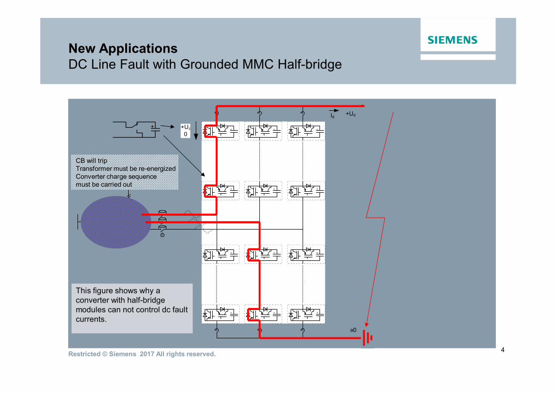
New ApplicationsDC Line Fault with Grounded MMC Half-bridge
This figure shows why aconverter with half-bridgemodules can not control dc faultcurrents.
4
CB will tripTransformer must be re-energizedConverter charge sequencemust be carried out

Restricted © Siemens 2017 All rights reserved.
+Ud
0
Id
M
New ApplicationsDC Line Fault with Grounded MMC Full-bridge
This figure shows why aconverter with full-bridgemodules can control dc faultcurrents.
3
+ + +
+ + +
+ + +
+ + +
+Uc
0-Uc
CB remains closedTransformer remains energizedConverter remains charged

Restricted © Siemens 2017 All rights reserved.
New ApplicationsFast DC Line Fault Clearing – the key for System Stability

Restricted © Siemens 2017 All rights reserved.
Advantages and Benefits of Classic (LCC) HVDCand Siemens HVDC PLUS (VSC) Technology
Characteristics SIEMENS HVDC LCC Technology(“Classic“)
SIEMENS HVDC VSC Technolgy(HVDC PLUS)
Rating “Classic“ ≤ 4 GW“Bulk“ ≤ 10 GW
“Smart“ ≤ 1,100 MVA (Cable)Full Bridge ≤ 2200 MVA (Overhead)
Overload Capacity Thyristor - very high IGBT strictly limited
Total Converter & Station Losses ≤ 1.5 % close to 2 %
Voltage, POD & Frequency Control Available Available
Dynamic Performance High Very High
Filter Requirements Typically. 50 % (in MVAR) of reatedpower transmission capability
None
Independent Control of ReactivePower
Stepwise linear Fully linear
Space Requirements High Less
Grid Access for weak AC Networks Restricted (with additional measures likeinstallation of Synchronous Condensers(SCO))
Quite easy
Supply of passive Networks andBlack-Start Capability
No Yes
Reversion of Current Polarity forMultiterminal Schemes
complexe DC-SWY in LCC-MultiterminalStations required
inherent converter function
*Value for transmission - Highlighted boxes: yellow andgrey
*Very High *High

Restricted © Siemens 2017 All rights reserved.
Common HVDC Misconceptions/Comments
• HVDC Classic cannot be used in a weak system
• Only VSC can support system voltage
• VSC contributes to the short circuit current
• VSC is only good for about 1000MW
• HVDC causes big problems to generators
• HVDC is only for bulk long distance Transmission
• HVDC is inflexible

Restricted © Siemens 2017 All rights reserved.
Real Time Power ControlTrans Bay Cable Data
-200
-150
-100
-50
0
50
100
150
0
50
100
150
200
250
300
350
400
450
0 24 48 72 96 120 144
Weekly MW/MVAR Ramping
MW MVAR PIT MVAR POT
MW
MVA
R
Saturday Sunday Monday Tuesday Wednesday FridayThursday

Restricted © Siemens 2017 All rights reserved.
Common HVDC Misconceptions/Comments
• HVDC Classic cannot be used in a weak system
• Only VSC can support system voltage
• VSC contributes to the short circuit current
• VSC is only good for about 1000MW
• HVDC causes big problems to generators
• HVDC is only for bulk long distance Transmission
• HVDC is inflexible
• HVDC is expensive
• Why can’t HVDC be more like AC?

Restricted © Siemens 2017 All rights reserved.
HVDC Products andSolutions - Overview
HVDC
Renewables & WeakSystems
HVDC Classic HVDC PLUS
UHV DC (800 kV,1100 kV)
Off-shore On-shore
Long Distance
Multiterminal
Islanded AC Systems
Single Wind Parks
DC Grid (multi-vendor)
Long Distance OHL(VSC FB / DCCB in MP or BP)
Long Distance Cable(VSC HB in sym. Monopoles)
Back-to-Back
Non-selective and selectiveMultiterminal
Back-to-Back
On-shore

Restricted © Siemens 2017 All rights reserved.
Thank You
Peter KohnstamHVDC Business DevelopmentManager
4601 Six Forks RdRaleigh, NC 27609
Mobile: +1 (919) 917 8096
E-mail:[email protected]
siemens.com/answers