december 2017 lrfd bridge design 2-1 2017 lrfd bridge design 2-3 cross slopes on bridges 1) the...
TRANSCRIPT
DECEMBER 2017 LRFD BRIDGE DESIGN 2-1
2. GENERAL DESIGN AND LOCATION FEATURES
2.1 Geometrics
2.1.1 Bridge Geometrics
The design of a bridge typically takes place in two major phases of work: preliminary design and final design. During preliminary design, the structure type, the foundation type, the aesthetics, and the primary geometry for the bridge are determined. During final design, specific details for all of the elements of the bridge are developed and presented in the plan set. These details include material descriptions, quantities, and geometric information. Final plan sets are typically assembled in an order that roughly follows the order of construction, from the ground up. This section of the manual contains a large amount of information useful for the preparation and assembly of plans for a project. To facilitate the production of plans and standardize the content of bridge plan sets, the Bridge Office has developed special provisions, standard bridge details, standard plans, standard plan notes, and standard pay items. Guidance for the design of specific structural elements (e.g. beams, abutments, piers, etc.) is provided elsewhere in the manual. Definitions For discussion of bridge geometrics in this section, roadways are classified as Mainline Highways, Ramps, Local Roads, and Local Streets. Each of these four groups is further classified under either Urban or Rural Design. The following definitions apply: Mainline Highways – Roadways that carry through traffic lanes for
freeways, expressways, and primary and secondary highways. Local Roads – Rural roads off the state trunk highway system. Local Streets – Urban roads off the state trunk highway system. Ramps – Segments of roadway connecting two or more legs at an
interchange. Urban Design – Roadways with curbs on the right and/or left sides. Rural Design – Roadways without curbs. Median Width – The distance between the inside edges of opposing
through traffic lanes. Auxiliary Lane – A lane adjoining a through traffic lane for a purpose
supplementary to through traffic movement such as truck climbing, weaving, speed change or turning.
General Criteria The width of the bridge deck and the typical section at the bridge undercrossing are determined by the classification and geometrics of the approaching roadway, together with appropriate design considerations for

DECEMBER 2017 LRFD BRIDGE DESIGN 2-2
2.1.2 Bridge Deck Requirements
shoulder needs. The geometrics of the approaching roadway are to be carried over and under the bridge to the maximum extent practicable. Bridge width requirements are a function of the lane and shoulder widths of the approaching roadway, together with assessment of pedestrian and bicycle needs, multimodal requirements, user safety requirements, drainage requirements, staging, and other project specific considerations such as snow storage and emergency vehicle access. The determination of the appropriate width for each project requires study of specific project needs. Detailed decision documentation is required by the Roadway Designer during the preliminary design phase, and must be coordinated with the Preliminary Bridge Plans Engineer. Bridge shoulder and lane widths should be included with project design element documentation in the District project design memo, including design exceptions as necessary. The discussion of geometric details included in this section describes bridge deck geometrics separately from bridge undercrossing geometrics. For side clearances at certain undercrossing situations, both a “desirable” and a minimum section are given. Application of Standards Unless stated otherwise, the geometrics discussed in the following articles apply specifically to new work. However, use of these geometrics is also highly desirable when upgrading or widening existing facilities and should be incorporated in those situations also. For bridge repair projects, see the Bridge Preservation and Improvement Guidelines, found on the MnDOT Bridge Office web site, for more information. Bridge deck geometrics on the local road system must comply with State Aid for Local Transportation Operations Rules, Chapter 8820. Responsibility The Preliminary Bridge Plans Engineer will be responsible for assuring that the geometric standards in this section are followed. Where a deviation from the standard is necessary, a written description of the deviation shall be prepared by the Preliminary Bridge Plans Engineer and submitted to the State Bridge Engineer for approval prior to submitting the Preliminary Bridge Plan for signature. Bridge Width Criteria Refer to MnDOT Technical Memorandum No. 12-14-B-03 for bridge width criteria. (Note that after the memorandum expires, contact the Preliminary Bridge Plans Engineer for guidance on bridge width.)

DECEMBER 2017 LRFD BRIDGE DESIGN 2-3
Cross Slopes on Bridges 1) The cross slope on bridge traffic lanes is the same as the approaching
roadway lanes, normally 0.02 ft./ft. The shoulder on a bridge may continue at the adjacent lane cross slope or, if better drainage is desired, may be 0.005 ft./ft. greater than the adjacent lane. If a shoulder functions as a pedestrian access route, cross slopes must not exceed 0.02 ft./ft. to be ADA-compliant. When the bridge deck is superelevated, provide the same slopes for the shoulders as the adjacent bridge traffic lanes. The 0.005 ft./ft. maximum cross slope change between adjacent lanes and shoulders is determined for constructability by limiting the need for atypical detailing such as special bar bends in the deck. Also note that the greater the change in cross slope, the more difficult it is to remove snow to bare pavement. The effects of a changing cross slope are magnified on curved alignments and require additional consideration and adjustment of stools, seat elevations, and resulting encroachment on vertical clearances. Keep superelevation transitions off bridges. In instances where they are unavoidable, it is preferable for ease of deck placement to maintain a straight line across the deck at all locations, because it allows a straight screed between paving rails placed at both sides of the deck. Locate begin and end points of transition breaks at piers.
2) Keep ramp cross slopes uniform between the bridge curbs with a slope of 0.02 ft./ft. to the right unless superelevated.
Bridge Median On divided highways with a separate bridge for each roadway, the openings between bridges must be a minimum of 8'-0" wide if access for bridge inspection vehicles is required. Use longitudinal joints along the median of bridges only on bridge roadways wider than about 100 feet or for other special cases. By eliminating this joint on bridges with medians, simpler detailing and simpler construction can be used. Shared-Use Paths and Pedestrian Walkways (Sidewalks) on Bridges Shared-use paths are provided on bridges where both pedestrian and bicycle traffic is expected. Bridge walkways are provided where only pedestrian traffic is expected.

DECEMBER 2017 LRFD BRIDGE DESIGN 2-4
The width of bridge shared-use paths and walkways are highly dependent on their context (i.e., factors such as land use, user type, expected volume, state and local non-motorized plans, network connections, trip attractions, overlooks, future growth, and bridge length). When including pedestrian and/or bicycle traffic on a bridge, note that safety, accommodation, and cost must be balanced for all users throughout the roadway cross section. This includes balancing the widths of lanes, shoulders, shared-use paths, and walkways, particularly in constrained cross-sections. The AASHTO Guide for the Development of Bicycle Facilities (GDBF) recommends a minimum two-way shared-use path paved width of 10 feet. The Proposed Guidelines for Pedestrian Facilities in the Public Right of Way (PROWAG) requires a continuous minimum clear public access route (PAR) width of 4 feet and a minimum clear PAR width of 5 feet at intervals of 200 feet to allow for passing. On bridges, MnDOT also includes a buffer width added on each side of the shared-use path/walkway in order to protect users from vertical barriers and edge of walkway drop-offs. Use the following guidance for determination of bridge shared-use path/walkway widths. For local bridges, also refer to State Aid Operation Rules, Chapter 8820. 1) New vehicular bridges
Best practice is to provide continuity by matching the measured width of the approach shared-use path/walkway, and adding a 1 foot buffer width on each side. See Figure 2.1.2.1. For approach shared-use paths/walkways that are located immediately behind a curb, the approach width is measured to the back side of the curb. Integral brush curbs (maximum of 2 inches wide x 6 inches high) may be included in the clear width dimension where the total width is greater than 10 feet. For approach shared-use paths not meeting the AASHTO GDBF recommended minimum width of 10 feet, consult state or local plans and/or the appropriate trail authority to identify the future intent and feasibility of providing a greater approach path width. Consult with functional group experts as necessary. Total bridge shared-use path/walkway widths greater than best practice or greater than 12 feet require consultation with the state or local authority and/or the appropriate trail authority to identify the need

DECEMBER 2017 LRFD BRIDGE DESIGN 2-5
for additional width. The District and/or local authority must document the need for and feasibility of providing this width (plan, cross section, letter, user volume, etc.). Total widths beyond 12 feet require concurrence from functional group experts and discussion to determine whether municipal cost participation is necessary. The minimum total bridge shared-use path width for new vehicular bridges is 10 feet, which is based on an 8 foot approach shared-use path (two times the 4 foot PAR width) plus a 1 foot buffer width on each side. Consideration may be given to a minimum total bridge shared-use path width less than 10 feet when the approach shared-use path width is less than 8 feet and/or there is concurrence from functional group experts. For new vehicular bridges that accommodate pedestrian traffic only, the minimum total bridge walkway width is 7 feet, which is based on the 5 foot PAR width for passing plus a buffer width of 1 foot on each side. The total bridge shared-use path/walkway width is defined as the minimum clear width measured from the path/walkway side of the curb/barrier/parapet/railing to the path/walkway side of the opposite curb/barrier/parapet/railing. For situations where there is no barrier/parapet on the traffic side of the shared-use path/walkway (raised sidewalk), the measurement is to the top outside edge of the shared-use path/walkway. There, the location of the top outside edge of the shared-use path/walkway is defined as 1 inch from the gutter line (based on 6 inch curb height x 0.125 slope = 0.75 inches, rounded up to 1 inch). Integral brush curbs (maximum of 2 inches wide x 6 inches high) may be included in the clear width dimension where the total shared-use path/walkway width exceeds 10 feet. See Figure 2.1.2.1.
2) New pedestrian bridges For new pedestrian bridges that carry both pedestrians and bicycle traffic, follow the guidance given in 1) above. For new pedestrian bridges carrying pedestrians only (note that this is a rare occurrence), the minimum total bridge walkway width is 8 feet per the requirements of AASHTO’s A Policy on Geometric Design of Highways and Streets.
DECEMBER 2017 LRFD BRIDGE DESIGN 2-6
3) Bridge repair projects Where possible, follow the guidance given in 1) above for bridge repair projects.
On bridge repair projects with constrained cross-sections, the minimum total bridge shared-use path width is 8 feet. On bridge repair projects with constrained cross-sections that accommodate pedestrian traffic only, the minimum total bridge walkway width is 5 feet. Consideration may be given to a minimum total width of no less than 4 feet where constrained bridge cross-sections are less than 200 feet long and there is concurrence from functional group experts. See Figure 2.1.2.1.
When the design speed on the bridge is 50 mph or greater, a concrete barrier that meets TL-4 is required between the roadway and the shared-use path/walkway. In addition, a pedestrian or bikeway railing is required on the outside of the shared-use path/walkway. For design speeds of 40 mph or less, separation with a concrete barrier is not required. For a design speed of 45 mph, consider the context when determining whether separation is needed:
Built up urban areas versus open suburban/rural areas. Proximity of approach shared-use path/walkway to roadway and
whether there is adequate cross-section width to provide and terminate approach guardrail.
Proximity of intersections to the bridge and whether intersection sight distance will be affected by inclusion of barrier and guardrail.
Volume of pedestrian/bicycle usage on the bridge. Actual operating speed compared to the design speed. Horizontal alignment and location of the shared-use
path/walkway. The curb height for shared-use paths/walkways adjacent to the roadway is 6". When a barrier is provided between the traffic lanes and the shared-use path/walkway, use the bridge slab for the shared-use path/walkway (i.e., do not provide a raised shared-use path/walkway). Advise the road plans designer to provide for any necessary shared-use path/walkway ramping off the bridge. The minimum cross slope for shared-use paths/walkways is 0.01 ft./ft.

DECEMBER 2017 LRFD BRIDGE DESIGN 2-7
Figure 2.1.2.1

DECEMBER 2017 LRFD BRIDGE DESIGN 2-8
2.1.3 Bridge Undercrossing Geometrics
Protective Barriers at Bridge Approaches The ends of bridge barriers must be protected from being impacted (except on low speed roads such as city streets). For design speeds over 40 mph, a crash tested guardrail transition is required. Refer to State Aid Operation Rules, Chapter 8820 for guardrail requirements on local bridges.
General Criteria for Lateral Clearance Bridge undercrossing geometrics must rationalize safety requirements with costs and physical controls such as span length and permissible depth of structure. The following guidelines apply in establishing these geometrics: 1) Safety
Piers, abutments, side slopes and back slopes steeper than 1:3, and guardrails can all be hazards to an out of control vehicle. It is desirable at all bridge undercrossings to provide a clear zone recovery area beside the roadway that is free from these hazards. This clear zone is given in the Road Design Manual, Section 4-6.04 and is a function of the roadway curvature, design speed, ADT, and ground slope. For the area under bridges a practical maximum clear zone of 30 feet may be used as permitted in the 2011 AASHTO Roadside Design Guide, Table 3.1 based on consistent use and satisfactory performance. Eliminate side piers from the roadside area wherever possible. The “desirable” bridge undercrossing will satisfy the above safety criteria. For locations where it is totally impractical to provide a full clear zone recovery area at an undercrossing (as at some railroad underpasses and in certain urban situations), lesser side clearances are permitted. Where the full recovery areas must be infringed upon, use the greatest side clearances that circumstances will permit. For example: A side clearance of 20 feet is not as desirable as 30 feet but is still better than the absolute minimum clearance. Where drainage must be carried adjacent to the roadway passing under a bridge, either a culvert must be provided at the approach fill or the ditch section must be carried through at the toe of the bridge approach fill. The use of a culvert will often permit more desirable bridge geometrics, but the culvert openings can also introduce a roadside hazard, requiring guardrail. A determination regarding drainage (need for culverts, size of a culvert, and assessment of possible hazard) will be a controlling factor in deciding geometrics of the bridge for the site.

DECEMBER 2017 LRFD BRIDGE DESIGN 2-9
2) Economics Prestressed concrete beam spans are normally the most economical type of construction for grade separations. In addition, there will usually be greater economy in constructing grade separations using two long spans rather than constructing four shorter spans. The span lengths and overall bridge length affect the abutment heights, which in turn affect the overall cost of the bridge. See BDM Article 2.3.2 under Abutment Type for a discussion on abutment height.
3) Appearance The use of longer spans will necessitate a deeper superstructure and higher approach fills. Consideration should be given to the effect of the depth of structure on the overall appearance and design of the undercrossing. For rough calculations during preliminary planning, the depth of highway bridge superstructures can be assumed to be about 1/20 of the length of the longest span. (Depth of superstructure refers to the dimension from top of slab to bottom of beam.) Contact the Preliminary Bridge Plans Engineer for the exact dimensions to be used in final planning and for depth of structure on railroad bridges.
Lateral Clearance for Roadways The desirable lateral clearance right and left from the edge of through traffic lanes to any hazard (as described above) is the full clear zone. Although guardrail may still be required outside of the bridge limits when the full clear zone cannot be met, 30'-0" may be used as a practical maximum lateral clearance in the area under bridges. Eliminate side piers wherever possible. Lateral Clearance for Railroads Lateral clearances at railroads are to be determined as follows: 1) The statutory clearances diagram shown on Figure 2.1.4.7 represents
the absolute minimums that must be adhered to. For design, use a minimum horizontal clearance of 9'-0" to a pier or abutment (8'-6" is the legal minimum).
2) MnDOT and FHWA have agreed to the horizontal clearances shown in
Figure 2.1.4.7 (25'-0" minimum clearance to pier, 30'-6" to “back slope control point”) for mainline BNSF RR tracks at sites meeting the following conditions: a) When the standard will not increase the cost of the structure by
more than $50,000.

DECEMBER 2017 LRFD BRIDGE DESIGN 2-10
b) When sufficient vertical clearance exists between the tracks and inplace or proposed roadway profile to accommodate the structure depth necessary for the longer spans typically required by the standard.
3) Back slopes shall be 1V:2H and pass through the “back slope control
point” shown on Figure 2.1.4.7 for the applicable case. The dimension to the “back slope control point” indicates the maximum extent of federal participation in the construction and must not be exceeded.
4) The Preliminary Bridge Plans Engineer will contact the MnDOT Office of
Freight and Commercial Vehicle Operations (OFCVO), to negotiate with the railroad the need for provisions for a maintenance road for track maintenance equipment and future track requirements.
Waterway Sections Under Bridges The Waterway Analysis (hydraulics report) gives information on the required stream cross section under the bridge including waterway area and low member elevation. Potential flood damage, both upstream and downstream, and permitting agencies’ requirements must be considered. For bridges on the local system, go to the State Aid Bridge Web Site at http://www.dot.state.mn.us/stateaid/bridge/handbook.html and refer to the guidance found under Hydraulics. Vertical Clearance for Underpasses Vertical clearance requirements are aligned with the 2011 edition of the AASHTO book, A Policy on Geometric Design of Highways and Streets, (see page 10-21), which recommends a minimum vertical clearance of 1'-0" above the legal vehicle height, plus an allowance for future pavement resurfacing and other considerations. The legal height of a truck in Minnesota is 13'-6". Table 2.1.3.1 lists the minimum vertical clearance requirements for trunk highway underpasses.

DECEMBER 2017 LRFD BRIDGE DESIGN 2-11
Table 2.1.3.1 Vertical Clearances for Underpass Bridges
Additional clearance to provide for future resurfacing is desirable and should be provided where practical.
Traditional bituminous overlay allowances range from 3” to 6”. Un-bonded concrete overlay projects are
now well above the 6” tolerance, and can be as high as 12”. The appropriate design value will depend
on the pavement types, its initial structure type, and lifecycle strategy, and should be coordinated with
the Pavement Design Engineer. A clearance height that includes a future resurfacing allowance may be used in place of the listed
minimums, provided the resulting clearance is at least as much as the listed minimums in this column.
Construction tolerance requirements have been reviewed and deemed adequate for new bridge
construction so long as the value shown for “Minimum Vertical Clearance for New Bridges” is used, rather
than AASHTO minimums. Adjust table values upward as required for overlay requirements exceeding
4”. The minimum vertical clearances shown are the absolute minimum clearances to be achieved after
pavement reconstruction, under an existing bridge or structure. These minimums are not to be used as
design minimums for new bridges or bridge reconstruction projects. The minimums are only acceptable
due to the known spatial location of the existing structure, thus eliminating the construction tolerance
risk of that existing element. A minimum vertical clearance of 16’-6” is required on designated Super Load OSOW Corridors. Super
Load OSOW Corridors are designed to accommodate an envelope size of 16’ wide x 16’ high x 130’ long,
TYPE OF STRUCTURE
MINIMUM VERTICAL
CLEARANCE FOR
NEW BRIDGES
MINIMUM VERTICAL CLEARANCE UNDER
EXISTING BRIDGES (FOR PAVEMENT
RECONSTRUCTION PROJECTS)
Trunk Highway Under Roadway
or Railroad Bridge (Super Load
OSOW Corridors)
16'-6" 16'-6"
Trunk Highway Under Roadway
or Railroad Bridge 16'-4" 16'-0"
Trunk Highway Under
Pedestrian Bridge 17'-4" 17’-0”
Trunk Highway Under Sign
Bridge 17'-4" 17’-0”
Railroad Under Trunk Highway
Bridge 23'-0" NA
Portal Clearances on Truss or
Arch 20'-4" 20’-0”

DECEMBER 2017 LRFD BRIDGE DESIGN 2-12
traveling along the corridor. Contact the MnDOT Office of Freight and Commercial Vehicle Operations
(OFCVO) for specific corridor locations and requirements (http://www.dot.state.mn.us/cvo/index.html).
The additional 12” of vertical clearance under pedestrian and sign bridges is provided because these
bridges are much less substantial and could collapse in the event of a hit. Vertical clearance over railroad infrastructure requires approval of the railroad. The 23'-0" clearance
above the top of the rails is the minimum clearance required by the American Railway Engineering and
Maintenance of Way Association (AREMA) manual. The maximum vertical clearance for Federal Cost
Participation is 7.1 meters (23’-4”) per the Code of Federal Regulations (see CFR 646 Appendix to
Subpart B of Part 646). This is allowed where it is the railroad’s standard practice to accomodate future
ballasting of the tracks. The State of Minnesota statutory minimum vertical clearance is 22'-0". For
clearances below 22'-0", approval from the MnDOT Office of Freight and Commercial Vehicle Operations
(OFCVO) and the railroad is required. Contact the Rail Safety and Coordination Project Manager from
the OFCVO for assistance with railroad coordination, agreements, and approvals.
Minimum portal clearance values were set based on historical portal heights.
The clearance over highways applies to the traffic lanes and full usable width of shoulders. Per Minnesota Rules, Chapter 8820, Local State-Aid Route Standards, the minimum vertical clearance for highway underpasses (including construction tolerance) is 16'-4" for rural-suburban designs and 14'-6" for urban designs. For trunk highways crossing local roads or streets at a freeway interchange, the minimum vertical clearance with construction tolerance is 16'-4". A complete list of vertical clearances for local roads and streets is found in the State-Aid Operations Rules, Chapter 8820. Where bikeways pass under a bridge or through a tunnel, a vertical clearance of 10'-0" is desirable for adequate vertical shy distance. (See AASHTO Guide for the Development of Bicycle Facilities, 4th Edition, pages 5-6 and 5-26.) Where this is impractical to obtain, a lesser clearance down to a minimum of 8'-0" is acceptable. Clearances below 10 feet on the local road system will require a variance to the State-Aid Operations Rules, Chapter 8. Vertical Clearance over Waterways The location and project description for all bridges over Minnesota waterways are to be reviewed by the U.S. Coast Guard (USCG) for potential permitting requirements.

DECEMBER 2017 LRFD BRIDGE DESIGN 2-13
1) Non-Navigable Waterways A 3'-0" minimum clearance between the 50-year flood stage and low point on the bridge superstructure is recommended. This amount of clearance is desired to provide for larger floods and also for the passage of ice and/or debris. If this amount of clearance is not attainable due to constraints relating to structure depth, roadway grades or other factors, reduced clearance may be allowed. The Preliminary Bridge Plans Engineer, after consultation with the Waterway Unit and the MnDOT District Office, will determine the required clearance.
2) Navigable Waterways a) Examples of waterways that require a construction permit
(generally considered to be waterways for commercial shipping) from the USCG include: The Mississippi River downstream from the railroad bridge that
crosses the river south of 42nd Avenue North in Minneapolis (River Mile Point 857.6)
The Minnesota River downstream from location just west of T.H. 101 river crossing in Shakopee (River Mile Point 25.6)
The St. Croix River downstream from Taylors Falls The St. Louis River downstream from Oliver, Wisconsin. Guide vertical clearances published by the USCG are: Mississippi River:
o 52.0' above 2% flowline elevation or 60.0' above normal pool elevation, whichever is greater, for the portion downstream of the Burlington Northern Railroad Bridge near the University of Minnesota (River Mile Point 853.0).
o 21.4' above river stage of 40,000 c.f.s. for the river portion upstream (River Mile Point 853.0 to 857.6).
Minnesota River: o 55.0' above normal pool elevation from the river mouth to
I-35W bridge (River Mile Point 10.8). o 30.8’ above 1881 high water elevation from I-35W bridge
(River Mile Point 10.8) to Shakopee (River Mile Point 25.6). St. Croix River:
o 52.0' above 2% flowline elevation or 60.0' above normal pool elevation, whichever is greater, from the river mouth to Stillwater.
Lake Superior Watershed: o Navigation clearances are determined by USCG on a case-
by-case basis.

DECEMBER 2017 LRFD BRIDGE DESIGN 2-14
2.1.4 Geometric Details
Consult the Preliminary Bridge Plans Engineer when establishing navigation clearances.
b) All Other Navigable Waterways Bridges that cross waterways in other portions of the state may be required to provide for local pleasure boat traffic. Vertical clearance for these bridges will be determined on an individual basis, based on local needs. The Preliminary Bridge Plans Engineer, after consultation the Waterway Unit, the MnDOT District Office, and the MnDNR, will make this determination based on specific conditions of the waterway.
Vertical and Horizontal Alignment Information governing vertical curves, horizontal curves, and sight distance may be found in the Road Design Manual and Technical Manual. When preparing preliminary bridge plans for the local road system, vertical and horizontal alignment charts from the State Aid Manual shall be employed. Specific geometric details for bridge decks and undercrossings are shown in the following figures:
Refer to MnDOT Technical Memorandum No. 12-14-B-03 (note that after the memorandum expires, contact the Preliminary Bridge Plans Engineer for guidance) for:
Figure 2.1.4.1 2-Lane Highway (Rural) Figure 2.1.4.2 2-Lane Highway (Urban) Figure 2.1.4.3 4-Lane Divided Highway (Rural) Figure 2.1.4.4 4-Lane Divided Highway (Urban) Figure 2.1.4.5 6-Lane Divided Highway (Rural) Figure 2.1.4.6 6-Lane Divided Highway (Urban)
Refer to this document for: Figure 2.1.4.7 Railroad Clearances
The figures noted above that are located in the technical memorandum show sections as viewed assuming traffic flow from bottom to top of page. Starting at the bottom of the sheet, the typical fill roadway section to a bridge approach is shown. The fill slope transitions to a 1:3 slope at the bridge. The section above it shows a section of this road on the bridge deck. The third section from the bottom is a continuation of the roadway as it approaches a crossing under a bridge; the back slope transitions to a 1:2 maximum slope at the bridge. The top section shows this roadway at the point where a bridge crosses this roadway.

DECEMBER 2017 LRFD BRIDGE DESIGN 2-15
Where a range of side slopes is shown on the approaching roadway section, Road Design should determine the slope used.
Figure 2.1.4.7 General Railroad Clearances
(Note that railroad approval is required for specific project clearances)

DECEMBER 2017 LRFD BRIDGE DESIGN 2-16
2.1.5 Bridge Barriers and Railings
2.2 Bridge Aesthetics
2.3 Preliminary Bridge Plans
2.3.1 General
See Section 13 of this manual for the policy on design of bridge barriers and railings for MnDOT projects. The aesthetic design process is initiated early in the bridge planning phase. Maximum levels of MnDOT participation in aesthetic costs are given in the Cost Participation and Maintenance Responsibilities with Local Units of Government Manual. The Preliminary Bridge Plans Engineer, the Preliminary Bridge Architectural Specialist, the District, and the financial stakeholders determine the aesthetic design level. Other people, offices, agencies, etc. may also be involved. The extent of this involvement may vary depending on the individual project. This process leads to the development of an Aesthetic Plan for the bridge. Once the project reaches the final stage, the Bridge Design Unit Leader implements the Aesthetic Plan to completion with assistance from the Preliminary Bridge Architectural Specialist as needed. Note that constructability of aesthetic components and complexity of the aesthetic details may affect the project schedule, and therefore need to be considered during the development process. Section 3 of the Aesthetic Guidelines for Bridge Design Manual describes the process of aesthetic design in more detail. Purpose The Preliminary Bridge Plan serves to document the main features of the bridge (type, size, location, aesthetics, etc.) and is used to obtain approvals and coordination before final design begins. By doing this, the time and expense of revising a completed plan will hopefully be avoided. The plan coordinates the work between Road Design and the Bridge Office and enables the cost and scope of the work to be estimated. Specific users of the plan include: Road Designers to verify the grade, alignment and roadway widths and
to obtain the approximate limits of grading, paving and guardrail at the bridge ends.
FHWA to review and approve unusual or complex bridge projects. Bridge Office Consultant Agreements Unit to select and negotiate
contracts with consultants. Final Bridge Design Units and Consultants to prepare final plans.

DECEMBER 2017 LRFD BRIDGE DESIGN 2-17
Bridge Scoping Engineer and Bridge Estimates Unit to prepare a preliminary estimate of the bridge costs.
MnDNR, U.S. Coast Guard, U.S. Corps of Engineers, and Watershed Districts to review and issue required permits for stream crossings.
Cities, Planning Agencies, and citizen groups to review and approve projects.
District Traffic Engineer and Regional Transportation Management Center (RTMC) to convey their needs on the new bridge.
MnDOT Office of Freight and Commercial Vehicle Operations (OFCVO) for use in negotiating railroad agreements.
In preparing preliminary bridge plans, the plan users should always be kept in mind, particularly those without bridge technical experience. Requirements for Preliminary Bridge Plans Preliminary bridge plans are required for all new trunk highway bridges (including MnDOT precast concrete arch and three-sided structures and pedestrian underpass box culverts) and all bridge widening projects where substructure widening is required. In addition, preliminary plans signed by the State-Aid Bridge Engineer are required for all county and local bridges that cross a trunk highway. Preliminary bridge plans are not required for culverts (except those used for pedestrian access), overlays, deck replacements, and other projects where substructures are not widened. The Bridge Preliminary Plans Unit normally prepares preliminary plans for new trunk highway bridges, although consultants may also develop plans. Preliminary plans for bridge widening projects are normally prepared by the Bridge Design Units since significant design work is required to evaluate the existing structure and schemes for widening and handling traffic. Preliminary plans prepared by Consultants or Design Units are submitted to the Bridge Preliminary Unit for review, acceptance, submittal to the State Bridge Engineer for signature, and distribution of signed copies. Contents The Preliminary Bridge Plan consists of a general plan and elevation sheet, survey sheet, and borings sheet. For complex urban structures additional road design sheets giving alignment, superelevation diagrams, utilities, contours, traffic staging, intersection layout, and aesthetics may be included. The Preliminary Bridge Plan contains: plan and elevation views, a transverse section, design data, data on the type of structure, foundation requirements, and aesthetic treatment. When aesthetics are of special importance, architectural type drawings showing the proposed treatment

DECEMBER 2017 LRFD BRIDGE DESIGN 2-18
or type of construction may also be included. For bridge widening projects, the survey sheet may be eliminated or a copy of the survey sheet from the existing bridge may be included. Preparation of Preliminary Bridge Plans The steps involved in preparing a typical preliminary plan set for a new trunk highway bridge by the Preliminary Unit are as follows: 1) Scoping Form A: Request for Bridge Scoping and Cost Estimating
Assessment is completed, which provides the initial information for the project. Bridge number is requested by completing New bridge number request form found at: http://www.dot.state.mn.us/bridge/bridgereports/index.html Bridge number is assigned.
2) Approved geometric layouts are received from the District. 3) Bridge survey sheets are received from the District Surveys Section.
Copies are sent to the Foundations Unit of the Office of Materials and Road Research requesting soil borings. For stream crossings, a copy is sent to the Bridge Office Waterway Unit requesting a waterway analysis.
4) A depth of structure and span arrangement are determined using the layout and waterway analysis and are given to Road Design. This typically involves communication between the Bridge Office, Road Design, and Hydraulics to arrive at a structure depth and span arrangement that produces the best overall solution. If a railroad is involved, negotiations are held with the railroad to determine what features should be incorporated into the plan to satisfy the railroad's needs and also meet MnDOT standards.
5) Final grades and alignment are developed and officially received from Road Design.
6) A CADD technician is assigned the project and drafting of the plan begins. Clearances are checked and more exact span lengths determined.
7) Traffic data is requested and received from the District Traffic Engineer.
8) The extent of aesthetic treatment is determined following the process described in BDM Article 2.2.
9) Borings are received electronically from the Foundations Unit and plotted on the survey sheets.
10) The Preliminary Bridge Plans Unit checks the completed preliminary package, except the foundation type.
11) The preliminary package is given to the Regional Bridge Construction Engineer along with the foundation report for determining pile type, lengths, and resistance. When received, the pile information is added to the preliminary plan.
DECEMBER 2017 LRFD BRIDGE DESIGN 2-19
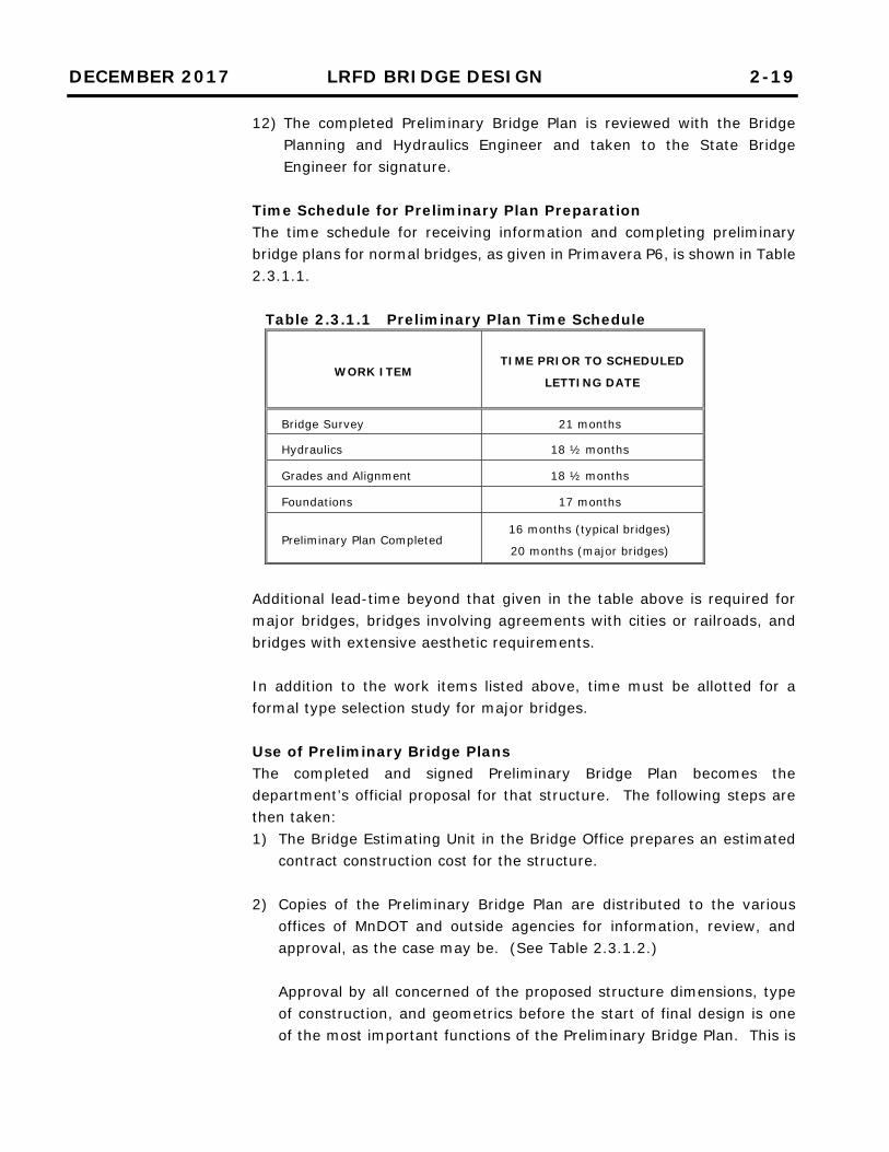
12) The completed Preliminary Bridge Plan is reviewed with the Bridge Planning and Hydraulics Engineer and taken to the State Bridge Engineer for signature.
Time Schedule for Preliminary Plan Preparation The time schedule for receiving information and completing preliminary bridge plans for normal bridges, as given in Primavera P6, is shown in Table 2.3.1.1.
Table 2.3.1.1 Preliminary Plan Time Schedule
WORK ITEM TIME PRIOR TO SCHEDULED
LETTING DATE
Bridge Survey 21 months
Hydraulics 18 ½ months
Grades and Alignment 18 ½ months
Foundations 17 months
Preliminary Plan Completed 16 months (typical bridges)
20 months (major bridges)
Additional lead-time beyond that given in the table above is required for major bridges, bridges involving agreements with cities or railroads, and bridges with extensive aesthetic requirements. In addition to the work items listed above, time must be allotted for a formal type selection study for major bridges. Use of Preliminary Bridge Plans The completed and signed Preliminary Bridge Plan becomes the department’s official proposal for that structure. The following steps are then taken: 1) The Bridge Estimating Unit in the Bridge Office prepares an estimated
contract construction cost for the structure.
2) Copies of the Preliminary Bridge Plan are distributed to the various offices of MnDOT and outside agencies for information, review, and approval, as the case may be. (See Table 2.3.1.2.) Approval by all concerned of the proposed structure dimensions, type of construction, and geometrics before the start of final design is one of the most important functions of the Preliminary Bridge Plan. This is

DECEMBER 2017 LRFD BRIDGE DESIGN 2-20
particularly true of stream crossings, railroad crossings (over and under), and structures requiring special aesthetic treatment. The Federal-Aid Highway Program (FAHP) provides federal-aid to State-selected projects. The Federal Highway Administration (FHWA) administers the FAHP on behalf of the U.S. Secretary of Transportation under Title 23 and therefore is one of the outside agencies that reviews bridge projects. The FHWA Minnesota Division and Minnesota Department of Transportation Stewardship & Oversight Agreement documents the roles and responsibilities of the FHWA and MnDOT regarding project approvals and review: For most bridge projects, MnDOT assumes the FHWA’s Title 23
responsibilities and only a courtesy copy of the Preliminary Bridge Plan transmittal letter is sent to FHWA (without the plans) for informational purposes.
For unusual or complex bridges and structures, the FHWA
Minnesota Division is responsible for the approval of the Preliminary Bridge Plan. For the purpose of this guidance, unusual or complex bridges and structures are defined as those that the FHWA Minnesota Division determines to have unique foundation problems, new or complex designs, exceptionally long spans, exceptionally large foundations, complex hydrologic aspects, complex hydraulic elements or scour related elements, or that are designed with procedures that depart from currently recognized acceptable practices. Examples of unusual or complex bridges and structures include cable-stayed bridges, suspension bridges, arch bridges, segmental concrete bridges, movable bridges, truss bridges, tunnels, complex geotechnical wall systems, and complex ground improvement systems.
When submitting preliminary documents to the FHWA, include the Preliminary Bridge Plan and supporting information. Supporting information includes all bridge/structures related environmental concerns and suggested mitigation measures, studies of bridge types and span arrangements, approach bridge span layout plans and profile sheets, controlling vertical and horizontal clearance requirements, roadway geometry, design specifications used, special design criteria, special provisions (if available), and cost estimates. In addition, submit hydraulic and scour design studies/reports which show scour predictions and related mitigation measures. Also submit geotechnical studies/reports along with information on substructure and foundation types.

DECEMBER 2017 LRFD BRIDGE DESIGN 2-21
For unusual or complex bridge projects, the State Bridge Engineer will submit one copy of the Preliminary Bridge Plan along with a transmittal letter requesting approval directly to the FHWA Division Bridge Engineer. The transmittal letter also includes the estimated contract construction cost of the structure. The FHWA is the only outside agency to which the Bridge Office sends a direct request for approval. All other outside agencies are contacted through other offices of MnDOT.
Note that the FHWA Headquarters Bridge Division is available for technical assistance on other Federal-aid and non-Federal-aid highways when requested.
3) The Preliminary Bridge Plan is used as a basis for preparing permit drawings to accompany applications to construct structures and approaches over navigable waters of the United States within or bordering our state. Such drawings are prepared in the Preliminary Plans Unit in accordance with detailed instructions issued by the U.S. Coast Guard. The Coast Guard is charged with the responsibility of issuing permits for bridges over navigable waters of the United States within or bordering our state. This includes all bridge spans (including land spans) from abutment to abutment. The Corps of Engineers is responsible for issuing permits for any other miscellaneous structures or work to be performed in navigable waters of the United States.
There are two Coast Guard districts that have jurisdiction within the State of Minnesota; the 9th Coast Guard District based in Cleveland has jurisdiction over the Duluth harbor and navigable portion of the St. Louis River, and the 8th Coast Guard District based in St. Louis has jurisdiction over the navigable portions of the Mississippi, Minnesota, and St. Croix Rivers. After receiving a permit application, the Coast Guard issues a public notice of application with prints of the permit drawings. These are sent to shipping interests, other agencies, displayed in post offices, etc. Generally, if no comments are received from others within 30 days of the notice of application, and if environmental statements have been submitted and a certification given by the Minnesota Pollution Control Agency, a permit will be issued. Correspondence to the Coast Guard is generally prepared for the signature of the State Bridge Engineer.

DECEMBER 2017 LRFD BRIDGE DESIGN 2-22
4) When all approvals have been obtained, the Preliminary Bridge Plan is used as the basis for the bridge design and for the preparation of final detailed plans. If the design is to be by a consulting engineer, the Preliminary Bridge Plan can also be used as the basis for negotiation of the consultant fee.

DECEMBER 2017 LRFD BRIDGE DESIGN 2-23
Table 2.3.1.2 General Distribution of Preliminary Bridge Plans
DISTRIBUTION TO
PURPOSE
REMARKS INFO. &
REVIEW
PRE-
APPROVAL
REQUIRED
District Project Manager x
District Pre-Design x
District Final Design x
District Construction x
District Environmental Coordinator x
District Hydraulics Engineer x For bridges that cross waterways.
District Maintenance x
District Bridge Engineer x
District Traffic Engineer x Send with request for determination of need for
lights, signals, conduit, and bridge mounted signs.
Office of Materials & Road Research –
Foundations Unit x
Regional Transportation Management
Center x
Send with request for determination of need for
conduit and mounting devices for surveillance
system.
Environmental Stewardship Office x
MnDOT Office of Freight and
Commercial Vehicle Operations (OFCVO) x For railroad crossings only.
Federal Highway Administration (FHWA) x x
Approval required for unusual or complex bridge
projects only. For all other bridges, a courtesy
copy is provided.
Bridge Final Design Unit x
Bridge Estimating Unit x
Bridge Waterway Unit x For bridges that cross waterways.
Bridge Consultant Agreements Unit x For bridge projects with consultant involvement.
Bridge Consultant x For bridge projects with consultant involvement.
Other Stakeholders x As needed.
DECEMBER 2017 LRFD BRIDGE DESIGN 2-24
2.3.2 Bridge Type Selection
Preliminary Plans for Local Bridges Consult the State Aid Bridge Web site at: http://www.dot.state.mn.us/stateaid/bridge/index.html for the submittal and approval process of State Aid Preliminary Bridge Plans. General The type of structure and span arrangement selected will depend on cost, depth available, geometrics, site conditions, and aesthetics. For some bridges this may be an obvious choice. For others it may involve a great deal of study, especially if aesthetics is a main concern. The section that follows gives some general guidelines on the selection process. Aesthetic Design Process
See Section 2.2 of this manual for a general discussion of the aesthetic design process.
Structure Type The most commonly used structure types and their characteristics are as follows: 1) Prestressed Concrete Beam
This is the most common structure type in Minnesota. Advantages include: low initial and future maintenance costs, high quality factory produced product, a stiff deck, and simple spans that accommodate tapers. Beams are limited to standard depths and straight segments, and a maximum length of about 200 feet. Beams in excess of 150 feet may require special shipping considerations.
2) Welded or Rolled Steel Beam This type of structure is well suited to complex urban freeways with limited depth, long spans, and complex geometrics. Steel beam bridges are also well suited for areas with bad soils, such as the Red River Valley, as steel allows the flexibility of modifying the bearing location and adding or reducing span lengths to accommodate shifting abutments and piers. Advantages include: a shallower depth of structure than prestressed concrete, beams with the ability to be field spliced to produce long span lengths, web plates that can be cut to any depth or to a haunched shape, beams that can be curved horizontally, and beams that can be painted a color which contrasts with the slab to make the structure appear thinner. Disadvantages include: a typically higher cost than other structure types, more difficult fabrication and inspection, a longer fabrication time, the possible need for initial painting and future maintenance painting, weathering steel staining of supports, and rusting of weathering steel when under salt exposure.

DECEMBER 2017 LRFD BRIDGE DESIGN 2-25
3) Cast-In-Place Concrete Slab Span This type of structure is used for shorter span bridges where depth is a major consideration. For simple spans conventionally reinforced, spans range up to 40 feet. Continuous spans are limited to about 60 feet. (See table in Section 5.3.1 of this manual for limits.) Advantages include: a minimum depth superstructure, ease of design and detailing, pleasing aesthetics, and economy for short span bridges. Disadvantages include: span lengths are limited, falsework is required, concrete delivery rate requirements may be a problem, a wearing course may be required to achieve a smooth ride, and the maximum skew angle is 45.
4) Concrete Box Girder Concrete box girders provide an attractive structure with high torsional resistance making them especially well suited for curved structures. The ability to accommodate an integral pier cap is an advantage since horizontal clearance is only required to the column top and not the cap top. Limitations and drawbacks may include the need for falsework, the inability to redeck or widen, and the higher construction cost.
5) Timber This bridge structure is used only on the local road system, for 1 or 3 spans with a maximum span length of about 25 feet. Advantages include: timber has a natural and aesthetically pleasing appearance, special equipment is not required for installation, and construction can be done in virtually any weather conditions. Disadvantages include: timber is not an economical structure type, it is limited to low-volume roads (roads with an AADT under 750), and the asphalt wearing surface tends to crack due to differential deck deflections.
6) Box Culvert Box culverts provide a quickly constructed and economical structure for stream crossings and pedestrian tunnels. Precast concrete box culvert standards are available for culverts up to 16 ft. x 12 ft. in size. Use of up to three large barrel boxes may be economical compared with a bridge. Advantages include: standardized plans, quick installation and low maintenance. Disadvantages include: span limitations, possible debris build-up when multiple barrels are used, and lack of a natural stream for fish unless the invert is lowered and riprapped.
7) Three-Sided Bridge Structure Three-sided precast concrete structures offer an alternative for short span structures up to 42 feet. Advantages include: quick installation, and a natural stream bottom. Disadvantages include: a higher cost

DECEMBER 2017 LRFD BRIDGE DESIGN 2-26
than cast-in-place structures, and pile foundations are typically required for stream crossings.
Not all bridge sites lend themselves to the use of the more common bridge types listed above. For these situations, specialized bridge types may be required, such as post-tensioned I-girder bridges, tied arch bridges, cable-stayed bridges, or extradosed bridges.
Abutment and Pier Locations The following guidelines aid in setting abutment and pier locations: 1) Water Crossings
For water crossings, keep the number of substructures located in the water to the minimum practical. Piers in rivers and streams block the natural flow of the waterway, trap ice and debris, impede navigation, and are subject to scour. In addition, construction of a pier in the water is expensive (especially if cofferdams are needed), and environmentally disturbs the stream/river/lake bottom and water quality. Ideally, set piers and abutments on shore to minimize dewatering and allow easy access for the Contractor. Set substructures to avoid interference with inplace substructures, including piling, wherever practical. Setting spans and structure depth involves balancing the hydraulic requirements of the low member elevation and waterway area with the constraints of approach grades, structure depth, and cost.
2) Grade Separations For grade separations fewer piers are also desirable wherever practical. Keep piers out of the clear zone unless absolutely necessary. In locations where ramps enter or exit a highway under a bridge, avoid piers between the mainline and ramp, if possible, as they restrict visibility.
When piers must be located in the median and within the clear zone, place the pier so it is equidistant to the inside edge of traffic lanes in both directions. This will maximize the buffer between the traffic and the pier.
Abutment Types Abutments can generally be classified into 3 categories: stub, semi-high, and high abutments. A further breakdown of abutments can be made according to the way expansion is handled – integral, semi-integral, or parapet type. 1) Stub Abutment: This is the shortest category of abutment, located at
the top of the fill slope with generally 2 to 4 feet of stem exposure.

DECEMBER 2017 LRFD BRIDGE DESIGN 2-27
Integral type stub abutments are the preferred type of abutment due to their jointless nature and simple construction. Semi-integral type stub abutments are the preferred type of abutment when the requirements for integral abutments cannot be met. Parapet type stub abutments with a berm were used extensively in the past on four-span freeway overpass structures. The use of longer two-span structures for overpasses and the move toward jointless abutments diminished its use, but this abutment type is still used where appropriate.
2) Semi-high abutment: This abutment type is located part way up the fill slope have become more popular as two-span overpasses have come into use. A higher abutment and elimination of the berm reduces the span length and depth of beam. This allows a lesser profile grade increase, resulting in lower grading costs. Limit exposed height of abutment face to approximately 8 feet, if possible. Undertake a cost evaluation of longer spans vs. taller abutments when considering a semi-high abutment. This category includes semi-integral and parapet type abutments only (integral abutments height restrictions limit them to the stub abutment category), with the semi-integral type preferred due to its jointless nature.
3) High abutment: This abutment type is located at the bottom of the fill
slope and is used primarily in congested urban design where structure depth is critical. Their use is discouraged since they are difficult to construct, expensive, and give a closed-in feel to the highway. Again, this category includes semi-integral and parapet type abutments only, with the semi-integral type preferred due to its jointless nature.
In locations where a high abutment would be required and use of a mechanically stabilized earth (MSE) retaining wall is economical, another option is a parapet type abutment supported by a pile foundation behind an MSE retaining wall.
Wingwalls parallel to the bridge roadway are used most often for aesthetic reasons. Flared wingwalls, typically with a flare angle of 45 degrees for bridges with no skew, will result in shorter wingwall lengths and less length of railing. Straight wingwalls, an extension of the abutment parapet, are the simplest to construct but are appropriate only for shallow beams where aesthetics is not a concern. See additional guidance regarding integral, semi-integral, and parapet abutments in Section 11 of this manual.

DECEMBER 2017 LRFD BRIDGE DESIGN 2-28
Pier Types 1) Water Crossings
Pile Bent Piers: These piers consist of a row of piles with a concrete cap encasing the pile top, and are the simplest and most economical type of pier. They are used for water crossings where a general maximum height from the top of pier to stream/river/lake bed is under 20'-0" and there is no ice or debris problem. Note that it is important to confirm by analysis that the pile unbraced length under a scour condition does not create instability in the pile. Spans must also be short enough to allow a single row of piles to support the deck at reasonable spacing. The piles act as columns, and bending strength to resist side impacts from ice or debris is important. For cast-in-place piles (the most widely used), a 16" minimum diameter is required. If H-piles are used, the upper portion is encased by a cast-in-place pile shell filled with concrete. Timber piles are not permitted. Concerns with pile bent piers include the potential to trap debris, pile stability, and appearance. Wall Type Piers: These piers consist of a single row of piles (usually H-piles) encased with concrete to form a wall. They provide more resistance to ice and debris and allow debris to pass through without becoming entangled on the piles. This type of pier is used where more resistance to ice and debris than afforded by the pile bent is needed, and yet the size and expense of a solid shaft pier can be avoided. This type of pier can be constructed by driving the piling, supporting the wall forms on the stream/river/lake bed, placing a seal with a tremie, dewatering, adding reinforcement, and pouring the wall. Pile stability can be a concern and must be evaluated. Solid Shaft or Multiple Column Piers: These piers are used for major water crossings where tall piers are required or where heavy loads or sizable ice and debris loads may occur. This type of pier includes a footing with the bottom of footing located a minimum of 6'-0" below the stream/river/lake bed. Construction of this type of pier involves driving sheeting to form a cofferdam, excavating inside the cofferdam, driving piles, pouring a seal, dewatering, and placing concrete.
2) Grade Separations Piers at grade separations are typically multiple column type with a cap. Piers are visible to passing motorists and the emphasis on aesthetics has led to more use of rectangular shaped column type piers, often with form liner treatments or rustication grooves. For narrow ramp bridges, a single shaft pier may be considered. Where aesthetics is not a concern, a round column pier will usually provide the lowest cost.

DECEMBER 2017 LRFD BRIDGE DESIGN 2-29
2.4 Final Bridge Plans and Special Provisions
For the majority of bridges over roadways, piers located within 30 feet of the roadway edge (defined as the edge of the lane nearest to the pier) must be designed to withstand a 600 kip load unless they are protected as specified in LRFD 3.6.5.1. This may impact the aesthetics by requiring inclusion of a crash strut. The alternative is to provide columns with a substantial cross-section designed to resist the crash load or protect them with a TL-5 barrier. See Article 11.2.3 of this manual for complete pier protection policy and requirements. For bridges over railroads, piers located within 25 feet of the centerline of railroad tracks must either be of “heavy construction” or have crash walls. Refer to Article 11.2.3.2.2 of this manual for complete requirements.
The primary purpose for preparing the Final Bridge Plan and special provisions is to communicate the geometric, material, and procedural requirements for the construction of a bridge. Several audiences will use the final bridge plan or contract documents during the life of the bridge. Initially, contractors use the documents to prepare their bids. A clear, accurate, and complete set of documents will result in competitive bidding. Well-communicated information reduces contractor uncertainty regarding what is required for different elements of construction. During construction, many parties will use the contract documents. For example, surveyors will locate and mark the position of working points, fabricators and construction engineers will prepare shop drawings and other submittals/drawings, inspectors and suppliers will use the documents for their work, and the contractor’s forces will use the documents. After construction of the bridge the detailed plans will be referenced when modifying the bridge (e.g., adding signage), performing load rating of the bridge, or rehabilitating/replacing the bridge. The Final Bridge Plan contains geometric information, a schedule of quantities and pay items for the bridge, traffic phasing (if applicable), limits of removal of existing structures and foundation items (if applicable), foundation details, substructure details, superstructure details, typical sections, utilities (if applicable), survey information, and other miscellaneous items. Specifications are also required for each project. They describe procedures for award and execution of the contract, how work will be measured and

DECEMBER 2017 LRFD BRIDGE DESIGN 2-30
2.4.1 Final Design Instructions
paid, procedures to be followed during execution of the work, and material and testing requirements for items incorporated into the project. Bridge projects use specifications from four different sources: 1) Most of the specifications used for a project are provided in MnDOT’s
Standard Specifications for Construction. They are necessarily general in nature and are intended to cover all types of MnDOT projects.
2) The Bridge Office has assembled additional specifications. Because
they are not included in the standard specifications they are called special provisions. A list of available standard bridge special provisions (2018 “SB” Bridge Special Provisions) is provided on the Bridge Office web site at: http://www.dot.state.mn.us/bridge/construction.html. Special provisions address a variety of work items, ranging from concrete placement to the fabrication and installation of expansion joint devices. Not all of the special provisions are intended to be used on every project; use only those applicable to the project.
3) The Bridge State Aid Unit has additional standard bridge special provisions that apply to local road bridge projects.
4) Custom special provisions. If a work item is of such unique character
that the standard specifications and the standard bridge special provisions don’t describe or address the work, a custom special provision will need to be prepared. Custom special provisions may be generated for any number of items. Items may include schedules (e.g., dates the contractor will have access to certain portions of the project) or lists of required submittals, etc.
In general, information that is highly graphical or geometric in nature should be presented on plan sheets. Large amounts of information conveyed with text should be assembled in special provisions. A specification or special provision usually contains the following five sections: 1) Description of work 2) List of the materials used (and their specifications) 3) Construction requirements for the work 4) Description of how the work will be measured 5) Basis of payment (pay item for the work)
Unless specified otherwise within this manual, design all structures in accordance with the current AASHTO LRFD Bridge Design Specifications.
DECEMBER 2017 LRFD BRIDGE DESIGN 2-31
2.4.1.1 Superstructure
2.4.1.1.1 Framing Plan
For those few cases where LRFD specifications have not been created or adopted, discuss options with the State Bridge Design Engineer prior to beginning final design. Design railroad bridges according to the current AREMA specifications for the live load specified by the railroad. Additional notes concerning the design of railroad bridges: 1) Railroad bridges will usually be designed with simple spans to avoid
uplift from the live load. 2) Bridges for the Duluth Mesabe & Iron Range Railway require a special
live load. Plans and documents prepared during the preliminary design phase should be reviewed prior to beginning final design. These documents include: 1) Preliminary Bridge Plan 2) Bridge Construction Unit Foundation Recommendation Report 3) Design Study Report (if completed) 4) Preliminary Design Folder (found in ProjectWise) When reviewing preliminary plans, pay particular attention to geometry and utilities. Check the layout. This includes reviewing grades, stationing, end slopes, beams, railings, roadways, shoulders, and the median (if applicable). Space beams so moments in fascia beams will not be larger than moments in interior beams. For steel beams and pretensioned I-beams, deck projections beyond the centerline of the fascia beam should generally not exceed the smallest of: 1) Depth of beam: During construction, overhang support brackets that
support deck forms, safety walkway, etc., contain a diagonal member that is supported off the beam bottom flange. If the overhang exceeds the beam depth, analyze to check if bracing of the beam is required. Include a note in the bridge plan if bracing is required.
2) 40% of the beam spacing: This limit keeps the deck overhang moment and the exterior beam dead load within a reasonable range. If exceeded, Section 9 deck tables cannot be used and a special design is required.
3) Deck coping width + barrier width + 1’-0” + ½ flange width: This keeps the design truck wheel within the limits of the exterior beam top flange, thereby ensuring that the live load will not govern the deck overhang design.
DECEMBER 2017 LRFD BRIDGE DESIGN 2-32
2.4.1.1.2 Bridge Decks and Slabs
For rectangular pretensioned beams, deck projections beyond the centerline of the fascia beam should generally not exceed the smaller of: 1) 40% of the beam spacing: This limit keeps the deck overhang moment
and the exterior beam dead load within a reasonable range. If exceeded, Section 9 deck tables cannot be used and a special design is required.
2) Deck coping width + barrier width + 1’-0” + ½ beam width: This keeps the design truck wheel within the limits of the exterior beam top flange, thereby ensuring that the live load will not govern the deck overhang design.
Provide a minimum slab projection beyond the tip of the flange of 6 inches. For bridges with reinforced concrete decks or slabs, the deck or slab may be cast in one lift (monolithic) or two lifts (deck/slab plus low slump wearing course). Note that the wearing course and the future wearing course are separate and distinct items. Bridge Deck Protection Policy For new bridge decks and slab span superstructures, utilize: • High Performance Concrete (3YHPC). In remote areas of the state
where ready mix suppliers cannot produce 3YHPC, use Low Cracking High Performance Concrete (3YLCHPC).
• Monolithic Slabs (no separate wearing course). • Synthetic Fibers (a combination of micro and macro synthetic fibers). The Regional Bridge Construction Engineer shall determine the appropriate action on any individual exceptions to this policy after consultation with the District. A list of common conditions that may warrant exceptions is provided in Table 2.4.1.1.2.1. Note that these exceptions apply only to bridges with AADT greater than 2,000. For existing bridge decks and bridge slab span superstructures, refer to the MnDOT Bridge Preservation and Improvement Guidelines (BPIG) for guidance. Refer to the Bridge Foundation and Other Recommendations form for the bridge deck or slab requirements for each specific bridge.

DECEMBER 2017 LRFD BRIDGE DESIGN 2-33
2.4.1.1.3 Diaphragms and Cross Frames
Table 2.4.1.1.2.1 Bridge Conditions That Require Consideration of a Low Slump Wearing Course
Condition Commentary
1) Project locations where HPC concrete is
not available.
Not all MN concrete plants have successful history with HPC concrete
production and delivery.
2) Bridge is located on a constant grade <
0.83%.
Variations in superstructure deflections and finishing tolerances can
make positive drainage difficult.
3) Bridge has a continuous steel
superstructure with degree of curvature
> 10 degrees.
Behavior of steel superstructure deflections and rotation during
sequential pouring can be difficult to adequately predict to achieve
ride tolerance.
4) Skew > 30 degrees on 2 spans or more
with an aspect ratio (deck width/span
length) > 0.5.
Finishing rails must deflect uniformly to produce the most uniform
cross-section. Finishing of skewed bridges is best accomplished by
placing wet concrete uniformly on all beams within the span by
setting the finishing machine on a similar skew to substructures.
5) Bridge is located on a vertical curve with
approach grades > 3% and
support skews > 20 degrees.
Where a vertical profile and skew exists, the difference in elevation at
either rail may produce a warped superelevation if finished on skew.
6) Superelevation transition occurs on
the bridge.
Finishing machines cannot easily accommodate variable
superelevation breaks during a pour.
7) Bridge deck or slab has a longitudinal
construction joint due to traffic staging
or large deck width.
Multiple pour placements with longitudinal construction joints are
more prone to cracking during deflections incurred during the casting
sequence. A concrete wearing course placed after major deflections
have occurred results in better crack size control.
8) Variable width bridges such as single-
point interchanges that are difficult to
finish with a finishing machine.
Finishing machines have limited ability to expand width, and finishing
outside of the screed rail locations requires finishing equipment with
higher risk of placement irregularities.
Applies only to bridges with AADT greater than 2,000.
For most bridges, the orientation of the primary superstructure elements is parallel to the centerline of the bridge. Aside from slab bridges, most bridges in Minnesota are supported on multiple beam lines. The beam lines are typically spaced on 5 to 15 foot centers. These bridges usually have diaphragms or cross frames, which serve a number of purposes: 1) They provide compression flange bracing during erection and
construction of the bridge.

DECEMBER 2017 LRFD BRIDGE DESIGN 2-34
2.4.1.2 Pedestrian Bridges
2) They increase lateral load distribution (more beams or girders participate in carrying live loads).
3) They provide a load path for lateral loads to be carried from the deck to the bearings.
During final plan assembly, specify the type of diaphragm on the framing plan, the deck cross section, and the longitudinal section. For bridges with integral or semi-integral abutments, the end diaphragm also functions as an abutment element. Pedestrian bridges shall be designed in accordance with the Guide Specifications for Design of Pedestrian Bridges. Several additional constraints are placed on pedestrian bridges to ensure they are accessible, safe, and durable: 1) For guidance regarding determination of pedestrian bridge width, refer
to Article 2.1.2 of this manual under Shared-Use Paths and Pedestrian Walkways on Bridges.
2) The maximum grade permitted on a pedestrian bridge is 8.33%. A grade flatter than the maximum is preferable. When the grade equals or exceeds 5%, provide a 5'-0" platform for each change in elevation of 2'-6". Also, a handrail is required when the grade equals or exceeds 5% per ADA requirements.
3) Protective screening, preferably a chain link fence system or a railing system, must be placed on both sides of the bridge. The height of the fence or railing must be 8'-0" above the top of the sidewalk. For sites with special aesthetic treatments involving ornamental railings, a minimum height of 6'-0" will be allowed. Where a fence or railing system is also required on retaining walls that are connected to the bridge, it is recommended that the same system (chain link fence or railing) be utilized throughout.
4) Provide a 6'-0" clear platform at the bottom of each ramp. 5) Provide a platform at each abrupt change in a horizontal direction.
The minimum plan dimension for a platform is 5'-0" by 5'-0". 6) Lay out the profile grade such that there are no abrupt grade breaks at
expansion devices. 7) Only in the rare case where handicap accessibility need not be provided
can stairs be incorporated into a design. When stairs are provided, use the following guidelines: a) Provide stairs with a 1'-0" tread and a 6" rise. b) Adjust the sidewalk or superstructure elevations to make all risers
6" tall.

DECEMBER 2017 LRFD BRIDGE DESIGN 2-35
c) The preferred number of risers in a flight of stairs is 14 to 16. The maximum number is 19.
8) Detail the rails in accordance with the following: a) Refer to Section 13 of this manual for metal railing height and
spindle spacing requirements. b) When required, place handrails 2'-8" above the top of the deck.
9) Provide an electrical ground for continuous chain link fences, ornamental railings, and metal handrails. If appropriate, provide bicycle ramps on pedestrian bridges that contain stairs.
Materials Use steel, prestressed concrete, reinforced concrete, or timber for the superstructure of pedestrian bridges. Aluminum is not an acceptable material for use in any portion of the superstructure. The minimum structural steel thickness is 1/4 inch for pipe or tube sections and 5/16 inch for all other sections. The minimum thickness requirements do not apply to railings. Provide structural tubing details that are watertight or designed such that moisture cannot be trapped in or on the member to accelerate corrosion. Use MnDOT concrete mix 3Y42-M for the deck of a pedestrian bridge. The Brazilian hardwood known as IPE, though very durable, is not an accepted decking material on state or federally funded projects. If the use of IPE wood is desired by the owner, local funds are the only option for payment. Bridge Substructure Use reinforced concrete supported on piling, drilled shafts, or spread footings for bridge substructures as recommended in the Bridge Construction Unit Foundation Recommendations report. Incorporate drainage systems (Detail B910) into the abutments as needed. Bridge Superstructure To limit transverse deck cracking due to negative flexure, provide additional longitudinal bars in the top of the deck over the piers. Stagger the ends of the additional longitudinal bars to transition the capacity of the section. (See Figures 9.2.1.8 and 9.2.1.9.) Detail anchorages for the piers and abutments to resist uplift and overturning forces associated with wind loads.

DECEMBER 2017 LRFD BRIDGE DESIGN 2-36
2.4.1.3 Temporary Bridges and Widening
2.4.1.4 Bridge Approaches
Provide a cover plate over all pedestrian bridge expansion joint openings to protect pedestrians from a tripping hazard. Type 5.0 strip seals with expansion joint openings up to 5.0 inches are allowed on pedestrian bridges since the joint is concealed by a cover plate. Highway Geometrics Meet MnDOT design standards for horizontal and vertical clearances for a pedestrian bridge over a roadway. Temporary Bridges Temporary bridges are used to detour traffic while removal of an existing bridge and construction of a new bridge occur on the mainline of the roadway. Design temporary bridges in accordance with the LRFD Specifications using the HL-93 live load with an associated load factor of 1.75. For posted speeds in work zones of 40 mph or less, design the barriers, the barrier/deck connection, and the deck overhang to meet railing Test Level 2. For speeds greater than 40 mph, design to meet Test Level 3. Temporary Widening Temporary widening occurs when staging requires widening of an existing bridge while construction of an adjacent new bridge occurs. Design structural components of the temporary widening to meet or exceed the capacity of the existing bridge components. For a temporary widening, match the deck material of the existing bridge. For temporary widening projects, design the barriers, the barrier/deck connection, and the deck overhang to meet the barrier test level required for the roadway. In most cases, the bridge approach panel will be included with the roadway grading plans for a project. Guidance for the treatment and details of approach panels can be found in the following:
Bridge Approach Treatment The approach treatment standard sheets describe the limits and treatment of excavation and backfill near the abutments. These sheets are found in the MnDOT Standard Plans Manual, Figures

DECEMBER 2017 LRFD BRIDGE DESIGN 2-37
2.4.1.5 Survey
2.4.1.6 Utilities
2.4.1.6.1 Suspended Utilities
5-297.233 and 5-297.234. The Preliminary Bridge Plan contains a note indicating which approach treatment sheet to use.
Bridge Approach Panel The standard sheets covering bridge approach panels are found in the MnDOT Standard Plans Manual, Figures 5-297.222 through 5-297.231. These figures cover standard approach panels for abutments with joints, abutments without joints, abutments with different amounts of skew, different mainline pavement types, and miscellaneous details. The Bridge Preliminary Plan contains a note indicating which approach panel sheets to use.
Specify a concrete wearing course on approach panels when the bridge deck has a concrete wearing course. The wearing course on the approach panels will be placed at the same time as the wearing course on the bridge. Include the approach panel wearing course quantity in the summary of quantities for the superstructure. When assembling the survey sheets for final plans, verify that the most current grading plans are being used. Include the centerlines and object lines for the abutment and pier footings on the final design survey sheets. Also identify and locate all test piles. The Bridge Office Preliminary Plans Unit in coordination with the District Traffic Engineer determines if provisions must be made for safety lighting (roadway, navigation, inspection, etc.), signing, or signals. Coordination is also done with the overall project manager regarding the need for other types of utilities. The conduit for utilities is to be suspended below the deck on hanger systems between the beams. Locate the entire conduit and hanger system above the bottom of the beams and generally below the diaphragms or in the lower openings of a cross frame diaphragm. To minimize the impact to the structure in the future, avoid casting conduits for utility companies in the deck, sidewalk, or barriers/parapets. Use polyvinyl chloride (PVC) coated hot dipped galvanized rigid steel conduit (RSC) for utilities requiring conduit. Use galvanized steel hangers and supports.

DECEMBER 2017 LRFD BRIDGE DESIGN 2-38
2.4.1.6.2 Buried Utilities
Roadway lighting conduit (11/2 inch diameter maximum) will be allowed in barriers/parapets (maximum of 2 per barrier/parapet) and sidewalks. Suspended water, sewer, communications, and electrical power (less than 35kV) utility systems are allowed on bridges. However, natural gas pipelines are considered a safety risk and will not be allowed. For hanging conduit systems on bridges with parapet or semi-integral type abutments, and when conduit is embedded in concrete barrier, deck, or sidewalk, use a combination expansion/deflection fitting at the abutments. This will accommodate horizontal movements (due to temperature change, creep, shrinkage, etc.) and vertical movements (due to jacking operations for bearing replacement, etc.). For hanging systems on bridges with integral abutments, only an expansion fitting is required at the abutments. The temperature movements of RSC approximate those of concrete. Consequently, lateral bracing is not needed. Choose a transverse spacing for the conduits that permits proper placement of concrete between embedded anchors. Typical conduit and utility details are available in the Bridge Office final design cell library, available at:
http://www.dot.state.mn.us/bridge/drafting-aids.html To protect structures, restrictions on the location of new or existing buried utilities and drainage pipes must be considered near bridge and wall structures supported on spread footings, and also near sheet pile and soldier pile walls. Location restrictions, installation techniques, protection measures, and review of plans for these utilities are required within 50 feet laterally, 50 feet below, and 15 feet above the base of foundations for these structure types. Utility installation in this region requires review and approval of the MnDOT Bridge Office. Additional restrictions on the location of utilities may be specified in other documents relevant to the project. The most restrictive requirements apply to the placement of utilities.
Within this region, three zones have been identified to provide general guidance for MnDOT approval. See Figure 2.4.1.6.2.1 for definition of the different zones. For purposes of this section, utilities are defined as any utility requiring a permit as well as State owned utilities and stormwater structures. Dry utilities are defined as facilities that do not carry fluid, examples include power and telephone. Wet utilities are defined as those

DECEMBER 2017 LRFD BRIDGE DESIGN 2-39
facilities that carry fluid or gasses, but do not include roadway edge drains or subsurface drains associated with the bridge or wall structure. All wet utilities in Zones 1, 2, and 3 require pipe with gaskets or joints designed to prevent leakage due to pressurized flow. Casing, where required, will meet MnDOT requirements for casing. Refer to the MnDOT Policy Statement on Accommodation of Utilities on Highway Right of Way for casing requirements. The following constraints for utilities in any of the three zones describe requirements for parallel installations, skewed, and perpendicular crossings.
The restrictions on utility placement are dependent on their position relative to the structure:
Zone 1 During the construction of the foundation, utilities are to be placed outside of Zone 1 when possible. If relocation is impractical or impossible, the requirements for locating utilities in Zone 1 are as follows: New utilities to be installed and existing utilities to remain in place
require Bridge Office approval. However, no new wet utilities may be placed longitudinally (i.e.,
parallel to the substructure or wall) in Zone 1. New utilities may be placed transversely (i.e., perpendicular to the
substructure or wall) to an existing structure in Zone 1, with Bridge Office approval of proposed design and construction sequencing.
All pipes and conduits must be designed for any surcharge loading due to structure bearing pressures and possible resulting deformations.
All wet utilities must be cased in Zone 1; if facilities are too large or cannot be cased effectively, a site specific design is required.
Utility owners may choose to case dry utilities to allow for future maintenance or access; however, casing is not required for dry utilities.
Future open trench excavation is prohibited in order to protect the foundation from potential undermining. Other forms of excavation may be permitted in this zone with Bridge Office approval.
Zone 2 The requirements for locating utilities in Zone 2 are as follows: New utilities may be installed in Zone 2. Excavation for maintenance or replacement will be permitted with
proper sheeting and shoring; no unbraced open cuts will be allowed.
DECEMBER 2017 LRFD BRIDGE DESIGN 2-40
Any utilities installed in Zone 2 must follow the same casing requirements as in Zone 1, with the exception of stormwater facilities.
Encasement is required for stormwater pipes with velocities greater than 10 fps, or pipe diameters 54 inches and larger, or pipe materials other than those shown in Standard Plate 3006. Other stormwater facilities need not be cased in Zone 2 unless required by contract specifications or as recommended by the Bridge Office.
Zone 3 There are no restrictions for utility installations in Zone 3 except for the requirement to use pipe with gaskets as needed for wet utilities.
If these conditions cannot be met, options include relocation or replacement of the utility or placing the substructure on deep foundations (piles or drilled shafts). However, pressurized wet utilities and large, high velocity non-pressurized wet utilities placed in Zone 1 of a deep foundation must be cased due to the risk of significant soil loss. In lieu of casing, a risk analysis approved by the Regional Bridge Construction Engineer is acceptable for substructures on deep foundations.
Certain types of utilities may pose a significant risk to shallow foundations when placed in Zones 1, 2, or 3, or to deep foundations when placed in Zone 1. If these types of utilities were to fail, the foundation would be at risk of failure due to the loss of material from localized scour or erosion. The determination of high risk utilities/high risk foundations will be made on a case by case basis by the Bridge Office and will be based on many factors including, but not limited to utility location, flow pressure, flow rate, structure size, and utility size. Additional restrictions to the ones contained in this document could be applied to utilities that pose a significant risk to the foundations.

DECEMBER 2017 LRFD BRIDGE DESIGN 2-41
Figure 2.4.1.6.2.1 Utilities Near Foundations

DECEMBER 2017 LRFD BRIDGE DESIGN 2-42
2.4.1.7 Precedence of Construction Documents
2.4.1.8 Design Calculation Requirements
2.4.2 Final Plans
Designers, while striving to produce accurate error-free construction documents, may at times end up with documents that have conflicting content. A hierarchy has been established to determine which content is governing for a project. In general, the more project specific the document, the higher the document’s position in the hierarchy. Section 1504 of the Standard Specifications for Construction describes the precedence of construction documents for a project:
If discrepancies exist between the Contract documents, the following order of precedence applies:
1) Addenda 2) Special Provisions 3) Project-Specific Plan Sheets 4) Supplemental Specifications 5) Standard Plan Sheets and Standard Plates 6) Standard Specifications
If discrepancies exist between dimensions in the Contract documents, the following order of precedence applies:
1) Plan dimensions 2) Calculated dimensions 3) Scaled dimensions
Office practice is to permit the limit states to be exceeded by a maximum of 3%. However, caution should be exercised to ensure that a 3% exceeded limit state at a particular location does not adversely affect the structure load rating. The plan order shall typically follow this list: General Plan and Elevation Cross Section and Pay Items Staging Plan Working Point Layout Removal Details Abutment Details and Reinforcement Pier Details and Reinforcement Framing Plan Beam Details Superstructure Details and Reinforcement Plan Details (Railing, Expansion Joint, Slope Paving, Conduit, etc.) B-Details As-Built Bridge Data

DECEMBER 2017 LRFD BRIDGE DESIGN 2-43
2.4.2.1 Drafting Standards
Surveys Borings Unrevised Informational Sheets When presenting geometric information, enough baseline information needs to be provided to permit others to verify the information presented. For example, the top of roadway elevations presented on a bridge layout sheet can be confirmed by others using vertical curve information on the general elevation and the cross slopes provided on the typical transverse section. In general, do not present the same dimensions several times. Providing dimensions in multiple locations increases the chance that not all dimensions will be updated as changes occur during the design process. The clarity of the details used in plan sets should be a primary concern of designers. Only the simplest details should combine the presentation of concrete geometry and reinforcement. In most cases there is less confusion if two details are used, one to convey concrete geometry and a second to identify and locate reinforcement. Show the initials of the individuals responsible for the design, drafting, design check, and drafting check on all plan sheets except the as-built sheet, survey sheets, boring sheets, and unrevised information sheets (such as those showing alignment tabulations, superelevation transitions, or aesthetics) taken from the preliminary bridge plan. Note that these unrevised informational sheets are to be placed at the end of the bridge plan. For the boring sheets, show the initials of the individuals responsible for the drafting and drafting check. Similarly, all sheets, except the as-built sheet, survey sheets, boring sheets, and unrevised information sheets must be certified by a Professional Engineer licensed in the State of Minnesota. In most cases, details are presented with stationing increasing as one moves from the left side to the right side of the sheet. Always include a north arrow on plan views. Plan views are typically oriented with north arrows pointing toward the top or to the right of the sheet. Stationing increases for northbound and eastbound traffic. The Bridge Office has adopted standards to be used when drafting plan sheets. Download Summary of Recommended Drafting Standards from:
http://www.dot.state.mn.us/bridge/drafting-aids.html

DECEMBER 2017 LRFD BRIDGE DESIGN 2-44
2.4.2.2 Drafting Guidelines
Sheet Layout and Continuity Read plans from a contractor’s perspective to check that they contain all information needed to build the bridge. Make sure enough dimensions are given for constructability. Use extra details for uncommon work. Use perspective views when clarity is needed. Use sheets efficiently. Balance the drawings on sheets to avoid one sheet being empty while another is crowded. Use additional sheets, as needed, to avoid crowding details on sheets. Make sure that details, data, and other information given on more than one sheet agree between sheets. Avoid unnecessary repetition of details and notes. Large-scale corner details are required for all skewed bridges and for other complex corners. Round dimensions to the nearest 1/8 of an inch. Note and dimension bar splices. Cross-referencing sheets to details is recommended. Use bill of reinforcement tables for all but very minor reinforced concrete work. Do not enlarge details (such as rebar bends) just to fill up space. Referencing bar bend details by letter to various generic shapes should never be used. Keep details together for abutments, piers, superstructure, etc. For abutments, piers, and other complex drawings, use different views and sections to separate dimensions and reinforcement. Place pile design loads and notes pertaining to a particular substructure on the sheet that contains the footing plan view. For bridges with numerous footings and curved alignment, a separate foundation layout drawing is recommended. If the plan contains numerous variable dimensions and other data (especially for framing plans and beams), make use of tables to keep this data in order. On the Framing Plan, show bearing type beside each bearing point instead of lines and arrows, which tend to clutter the drawing.

DECEMBER 2017 LRFD BRIDGE DESIGN 2-45
For simple beam spans (prestressed beams, etc.), dimension beam spacing at pier cap along centerline of the pier(s). Include supplemental dimensions along centerline of bearing for curved and flared structures. On projects with staged construction, use enough drawings to clearly indicate how the bridge construction is to be coordinated with the staging. Keep structure units together. Reinforcement and quantity tabulations are to be split between stages. On repair projects, clearly indicate cut lines and extent of all removals. If there is a saw cut, be sure to use a straight line (WT=5). If elevations are taken off original plans, note as such and require the contractor to verify elevations in the field. When it appears that plan notes, such as procedure descriptions, specifications, etc., will become excessively wordy, relegate these notes to the special provisions. List general notes first and specific numbered notes last. Number specific detail notes with circles and reference the detail to which they apply. Place all notes together on the right hand side of the sheet. Leave extra lines in the Summary of Quantities and Bill of Reinforcement for additions. Also, leave extra space in the list of notes. Pay Quantities Make computations neat and readable. Strive for continuity. These computations may be needed for future reference and the reader must be able to interpret them. Box in or underline computation totals for quicker take off. Initial, date, and put the bridge (or project) number on every computation sheet. Two sets of independently worked quantity computations are required for each pay item. Arrange design and quantity computations into a neat and orderly package. In addition to pay item quantities, compute informational quantities. Do not include these quantities in the bridge plan, but instead submit them to the Bridge Estimating Unit for use in developing the Engineer’s Estimate. Examples of information quantities include: summary quantities for conduit systems, summary quantities for drainage systems, cubic yard quantities for concrete items paid for by the square foot or linear foot, and

DECEMBER 2017 LRFD BRIDGE DESIGN 2-46
2.4.2.3 General Plan and Elevation
miscellaneous incidental items such as polystyrene and waterproofing membrane. Sample forms for reporting informational quantities are available at: http://www.dot.state.mn.us/bridge/design.html Additional Drafting Guidance Additional drafting resources can be found at:
http://www.dot.state.mn.us/bridge/drafting-aids.html These resources include:
Suggested Reinforcement Detailing Practices Guidelines for Checking Final Design Bridge Plans Bridge Preliminary and Final Design Seed Files Bridge Preliminary and Final Design Cell Libraries
The General Plan and Elevation sheet is intended to summarize the primary features and horizontal geometry of the bridge. Figure 2.4.2.3.1 shows an example General Plan and Elevation sheet and Figure 2.4.2.3.2 shows a Typical Cross Section sheet with pay items. Plan On the plan view identify the following: working points, working line, centerlines, utilities, location of inplace bridges or substructures, ditch drains, deck drains, lights, and nameplate. Label the following: span lengths, deck width, size of angles between the working line and centerlines, horizontal curves, minimum horizontal clearance to substructure units, point of minimum vertical clearance for each roadway under the bridge, extent of slope protection, roadway stationing and elevations, and distance between twin bridges. Provide a north arrow. Tie bridge dimensions to working points. Show the direction of traffic for each design lane. Elevation Present the primary vertical geometry of the bridge on the elevation view. This consists of vertical curve data, end slopes, existing ground lines, footing elevations, limits of excavation, grading notes, ditch clean out along railroad tracks, and scale. Label bearings as fixed, expansion, or integral. Also label piers, spans, abutments, and slope protection. For bridges over waterways, provide hydraulic information. Required information includes: channel bottom width, low member elevation, design high water elevation, and assumed flowline elevation.

DECEMBER 2017 LRFD BRIDGE DESIGN 2-47
For grade separation bridges, provide the minimum vertical and horizontal clearances. In addition, provide the dimension from centerline of pier to toe of slope protection. If there is no side pier, give the dimension from toe of slope to centerline of roadway. Dimension the pier, lane, and shoulder widths on the roadway under. Lane slopes on the roadway under are typically omitted, but can be provided if space permits. When illustrating slope protection use a straight slope line; do not follow the ditch radius curve. To reduce confusion concerning slopes, do not show slopes as 1:2. Many individuals are unsure of whether the first or second number is the horizontal part of the slope. Show the slopes graphically. Where slopes need to be provided in text, explicitly call out the slopes (e.g., 1V: 2H). Typical Cross Section The typical cross section is the third general view of the structure. Combined with the general plan and elevation views, the primary geometry of the bridge is conveyed. On the typical cross section show transverse bridge dimensions, lane widths and slopes, beam depth and spacing for all spans, roadway slab and concrete wearing course thicknesses, type of barrier, medians, sidewalks, profile grade location, working line, and all centerlines. For staged construction projects, provide the inplace, interim, and final cross sections, including temporary anchored or unanchored safety barrier locations. For complex projects, consider creating a separate plan sheet for pay items and notes for clarity. Utilities Show all utilities that may affect bridge construction. Note what is to be done with them (will they be moved, will they no longer be used or do they need to be protected during construction). Miscellaneous Provide a Design Data block on the General Plan and Elevation Sheet of the bridge plan set. The information given in the block provides a summary of the primary parameters used for the design. Information in the Design Data block includes: design specifications, design live load, design material properties, future wearing course load assumed in the design, deck area, traffic data, and the operating rating for the new structure. See Appendix 2-C.
DECEMBER 2017 LRFD BRIDGE DESIGN 2-48
Also on this sheet, identify the governing standard specifications for construction. Show a north arrow on the plan view and include a block for engineering certification. Present applicable project numbers on the first sheet; project numbers depend on specific funding sources, so there may be both state and federal project numbers. Review the title block to ensure it accurately describes the bridge. Within the title block provide span lengths to the nearest foot and the bridge type identification number. The three-character identification number should follow the numbering scheme provided in Appendix 2-A of this manual. Include any additional standard construction notes and the sheet list for the plan set on the first sheet of the plan set. Provide the schedule of quantities for the entire bridge in tabular form on the second or third sheet of the plan. Standard practice for placement of bench marks and bridge nameplates is as follows:
Place a single nameplate on the southeast corner of the bridge for a roadway running north and south. For a roadway running east and west, provide the nameplate at the northeast corner. On twin bridges (two one-directional bridges that are side-by-side, but each have their own bridge number), place a nameplate on each right hand corner approaching bridge. For railroad and pedestrian bridges, place the nameplate on a substructure unit. On bridges that are widened, redecked, or that receive rail modifications that result in additional roadway width, install a new nameplate with the original year completed and the year renovated.
Do not show a benchmark disk in the bridge plan. Placement of
bench mark disks on bridges is no longer needed. Check if ditch drainage pipe is necessary for the project. If drainage pipe is necessary and the contract has multiple portions (grading, bridge, etc.), identify which portion of the contract contains the pipe. Label ditch drainage pipe on plan and elevation views. Concrete or aggregate slope protection is used along a highway or railway (grade separation structures). Aggregate slope protection is used more frequently when pedestrian traffic below the bridge is limited. Stream crossings use riprap slope protection supported on a granular or geotextile filter. The Preliminary Bridge Plan will indicate the type of slope protection to be used.

DECEMBER 2017 LRFD BRIDGE DESIGN 2-49
Figure 2.4.2.3.1 General Plan and Elevation

DECEMBER 2017 LRFD BRIDGE DESIGN 2-50
Figure 2.4.2.3.2 Typical Cross Section

DECEMBER 2017 LRFD BRIDGE DESIGN 2-51
2.4.2.4 Bridge Layout and Staking Plan
The Bridge Layout Sheet is used by surveyors to locate the bridge in space with its primary geometry. The primary geometry consists of centerline of roadway(s) and centerline of substructure bearings. Working points are located on substructure bearing centerlines where they are intersected by fascia beam lines and working lines. By providing stationing, X-coordinates, and Y-coordinates for each of the working points, the position of the bridge can be fixed. Figure 2.4.2.4.1 contains an example. In Figure 2.4.2.4.1, the working line and its azimuth are labeled. Also shown is the angle of intersection between the working line and each of the substructure units and roadways under the bridge. As a primary geometry line, the working line should be labeled throughout the plan set. Place the control point at the intersection of the survey line and centerline of cross road, track etc. For river crossings, place the control point at an abutment centerline of bearing. Label the control point with its coordinates. Coordinates of the control point and the working points should be given to three decimals of a foot. Tie the working point layout to the control point. Present dimensions in feet (a note on the sheet should say the same). List the coordinates for all working points in a table labeled “DIMENSIONS BETWEEN WORKING POINTS”. Stations and the distances between working points should be presented to the nearest 0.01 foot. Coordinates are assumed to be given in the Minnesota State Plane Coordinate System. If another system is used, place a note on the sheet identifying the system used. In addition to horizontal geometry, a limited amount of vertical geometry is provided on the Bridge Layout Sheet. The vertical geometry consists of elevations and drops. The elevation at the top of roadway and the bridge seat is provided for all working points located on beam lines and is appended to the “DIMENSIONS BETWEEN WORKING POINTS” table. Drop or elevation difference information is provided for each substructure unit. Drop information is summarized in the “TOP OF ROADWAY TO BRIDGE SEAT” table. The table should contain the following items: 1) Deck Thickness 2) Stool Height 3) Beam Height 4) Bearing Height 5) Total Height

DECEMBER 2017 LRFD BRIDGE DESIGN 2-52
If the drop dimension is the same for all beam lines, provide a single value for each substructure unit. If the drop dimensions vary at substructure locations, provide a value for each beam line. Total values should be given in both inches and decimals of a foot to two places.

DECEMBER 2017 LRFD BRIDGE DESIGN 2-53
Figure 2.4.2.4.1 Bridge Layout

DECEMBER 2017 LRFD BRIDGE DESIGN 2-54
2.4.2.5 Standard Abbreviations
2.4.2.6 Inclusion of Standard Bridge Details and Bridge Standard Plans in Plan Sets
Use standard abbreviations to clarify information on plan sets and reduce the clutter on a crowded plan sheet. Appendix 2-B presents a list of standard abbreviations that can be utilized in a plan. Define abbreviations used in a plan set on the sheet where they are used or as part of a General Notes sheet. There are two parts to the Standard Bridge Details: Part I and Part II. They are published on the Bridge Office Web site at:
http://www.dot.state.mn.us/bridge/standards.html Bridge details are intended, where applicable, to be incorporated into a set of bridge plans. Bridge Details Part I, typically referred to as the B-Details, are presented in a “portrait” orientation on an 8 1/2" x 11" sheet. Included are details for nameplates, pile splices, bearings, diaphragms, steel superstructures, floor drains, and other miscellaneous details. Bridge Details Part II consists of details that occupy an entire plan sheet. The majority of these details are for barriers, parapets, medians, prestressed concrete beams, and expansion joints. Similar to Bridge Details Part II, Bridge Standard Plans are intended to be incorporated into bridge plan sets and occupy an entire plan sheet. The information presented may be much more in-depth as the information for multiple designs is presented on a single sheet. Bridge Standard Plans are only available for precast concrete box culverts. How standard details are incorporated into a bridge plan will depend on the amount of revisions needed to the details, falling into 3 categories:
1) Standard is unmodified: This is when the standard is used as drawn with no changes, or with all blanks filled in where expected. Box out and place cross-hatching across all specific details that do not apply. Do not remove them. It is not necessary to cross out alternative sizes in tables or alternate dimensions that are not used, or circled notes that are only referred to in the details that do not apply.
2) Standard is modified: This is when details, dimensions, or notes on the standard have been specifically modified from what is shown in the standard. In this case, place the word “MODIFIED” under the B-Detail or after the Figure Number. Also add a box containing a note stating what was modified to help plan readers quickly locate them. Do not “cloud” the changes.

DECEMBER 2017 LRFD BRIDGE DESIGN 2-55
2.4.2.7 Standard Plan Notes
3) Standard is substantially modified: This is when much of the standard is changed by extensive and/or numerous modifications to details, dimensions, and notes to the extent that it ceases to reflect the standard. It will require a judgment call on the part of the engineer as to when this category applies. In this case, remove the State Bridge Engineer approval block and the figure number. Note that for this case, the engineer takes full responsibility for the details shown on the sheet.
Note that these rules do not apply to box culverts, which are included with the road plan. Modification of box culvert standards is to be done in accordance with the Design Scene, Chapter 3 requirements, which can be found at:
http://www.dot.state.mn.us/pre-letting/scene/index.html Similar to other plan elements, standard plan notes have been prepared to increase the consistency of information presented on final design plans. Plan notes serve a variety of purposes; they communicate design criteria, specific construction requirements, and a variety of notes pertaining to the construction or fabrication of specific bridge elements. Appendix 2-C contains the Standard Plan Notes. These notes have been grouped into the following categories: Design Data and Projected Traffic Volumes Construction Notes Signature Block Drainage and Erosion Control Excavation and Earthwork Reinforcement Foundations Steel Materials, Fabrication, and Erection Concrete Placements Welded Steel Bearing Assemblies Cutting and Removal of Old Concrete Joints and Joint Sealer Timber Bridges Miscellaneous Designers unfamiliar with MnDOT’s Standard Plan Notes should review the list prior to beginning final design. Reviewing the notes prior to design will familiarize designers with the material properties to be used, and other constraints typically placed on construction. Perform a second review of the notes at the end of design to ensure that all applicable notes were incorporated into the plan set.

DECEMBER 2017 LRFD BRIDGE DESIGN 2-56
2.4.2.8 Quantity Notes and Pay Items
Standard Summary of Quantities Notes During construction, contractors are compensated according to the work they complete. The value of the work item is identified when the contractor submits their bid. For each work item or pay item the contractor must supply a price. The pay items are coordinated with specifications and special provisions. To clarify what is included in a specific pay item, the Bridge Office has assembled a Standard Summary of Quantity Notes. Like other plan elements, these notes help ensure uniformity across plan sets and permit MnDOT to generate a historical price database that can be used to estimate the cost of future bridges. The Standard Summary of Quantities Notes for bridge projects is listed in Appendix 2-D. Pay Items The current MnDOT list of pay items (commonly referred to as the Trns*port List) is located at the following link:
http://transport.dot.state.mn.us/Reference/refItem.aspx When populating the “SCHEDULE OF QUANTITIES FOR ENTIRE BRIDGE” in the bridge plan, it is important to note the following:
1) The Trns*port List shows a 12 digit number under the “ITEM NUMBER” column. Provide only the first seven numbers including the decimal point (all the numbers before the /) for each pay item in the bridge plan.
2) The Trns*port List shows two descriptions for each pay item. Choose the “ITEM SHORT DESCRIPTION” column for all pay item descriptions in the bridge plan.
3) Use the “PLAN UNIT NAME” column from the Trns*port List for listing the units in the bridge plan.
4) The item number, item description, and units must read exactly as shown in the Trns*port List, including spaces, dashes, parentheses, etc. In order to avoid errors, it is suggested to copy and paste them directly from the list into the bridge plan.
For each pay item shown in the plan, provide a reconciled quantity estimate. Some pay items are to be designated as “plan quantity pay items”, for which payment to the contractor will be based on the quantity given in the plan rather than measuring in the field. For these items, include a “(P)” as an appendix to the item label. For example:
2401.507 STRUCTURAL CONCRETE (3B52) 699 CU YD (P)
Pay items are to be designated as “plan quantity pay items” when the quantity for payment can be calculated using the dimensions given in the plan and the dimensions are not expected to change in the field. Some examples include:
DECEMBER 2017 LRFD BRIDGE DESIGN 2-57
structural concrete paid for by the cubic yard bridge slab concrete paid for by the square foot reinforcement bars paid for by the pound prestressed concrete beams paid for by the linear foot ornamental metal railing paid for by the linear foot
Some examples of pay items that are not “plan quantity pay items” include:
piling paid for by the linear foot (because plan quantity is an estimate only and final pile lengths are determined in the field)
random riprap paid for by the cubic yard (because plan dimensions are approximate and actual volume may differ)
removal and patching of concrete slabs paid for by the square foot (because actual area will be determined in the field)
structural excavation paid for by lump sum (because it is not a calculated value based on plan dimensions)
bearing assemblies paid for by the each (because it is not calculated using dimensions from the plan)
Miscellaneous Round off quantities to the nearest pay item unit except for the following: Earth excavation to nearest 10 cubic yards. Reinforcement bars and structural steel to nearest 10 pounds. Piling lengths to nearest 5 feet. When computing small bituminous quantities use the following:
Wearing course = 110 pounds / square yard / inch thickness Shoulder or Wearing Course (6.5%)
0.065 (thickness in inches) (110 pounds) = ___ pounds / sq. yard Tack Coat = 0.03 gallons / square yard Binder or Base Course (5.3%)
0.053 (thickness in inches) (110 pounds) = ____ pounds / sq. yard Compute deck area (rounded to the nearest square foot) by multiplying the transverse out-to-out bridge width by the longitudinal end-of-deck to end-of-deck distance. (Do not include bridge approach panels or paving brackets.) When computing structural steel quantities, increase the calculated weight by 1.5% to account for the weight of steel for welds and bolt stick-through.
DECEMBER 2017 LRFD BRIDGE DESIGN 2-58
2.4.3 Revised Sheets
Sometimes, revisions to the plan are required after the letting due to an error found in the plan or other issues that arise during construction. When this occurs, use the following procedure: 1) Revise the sheet as follows (See Figure 2.4.3.1):
i. Make the necessary revisions to the sheet. ii. In the revision block, provide the revision number within a triangle
border, the revision date, a description of the revision, and the initials of the engineer who approved the revision.
iii. “Cloud” the actual revisions to the sheet and include the revision number within a triangle border next to the “clouded” change. When sheets have been revised multiple times, remove previous revision “clouds”, only “clouding” the current revisions. However, leave previous triangles with their revision numbers in place.
iv. Change the sheet number by placing a “-R” and the revision number after the original sheet number. For example, revision 1 to sheet 7 will be designated “SHEET NO. 7-R1”, revision 2 will be designated “SHEET NO. 7-R2”, etc. For situations where an additional plan sheet must be inserted as part of the revision, repeat the preceding sheet number with an “A” after it. For example, as part of revision 1 where a sheet needs to be added between sheet 5 and 6, designate the revised sheet as “SHEET NO. 5A-R1”.
2) Plot and certify the revised sheet. 3) Draft a transmittal letter from the State Bridge Design Engineer to the
Resident Engineer in the District construction office. Submit the letter and the revised sheet to the State Bridge Design Engineer for signature and distribution. Memo templates are available on the Bridge Office network drive. Consultants should contact MnDOT Bridge Office Project Manager to obtain the file.

DECEMBER 2017 LRFD BRIDGE DESIGN 2-59
Figure 2.4.3.1

DECEMBER 2017 LRFD BRIDGE DESIGN 2-60
2.5 Reconstruction Guidelines and Details
2.5.1 Superstructure
2.5.1.1 Barriers
2.5.1.2 Wearing Course
2.5.1.3 Expansion/Fixed Joints
Typical details for the reconstruction of barriers, superstructure joints, and pavement joints are presented in this section. [Future manual content] [Future manual content] [Future manual content] The following figures show typical details for the reconstruction of expansion joints and fixed joints: Figure 2.5.1.3.1 Reconstruct Expansion Joint Type A Figure 2.5.1.3.2 Reconstruct Expansion Joint Type B Figure 2.5.1.3.3 Reconstruct Expansion Joint Type C Figure 2.5.1.3.4 Reconstruct Expansion Joint Type D Figure 2.5.1.3.5 Reconstruct Expansion Joint Type D Figure 2.5.1.3.6 Reconstruct Expansion Joint Type E Figure 2.5.1.3.7 Reconstruct Expansion Joint Type F Figure 2.5.1.3.8 Reconstruct Fixed Joint Type A Figure 2.5.1.3.9 Reconstruct Fixed Joint Type A

DECEMBER 2017 LRFD BRIDGE DESIGN 2-61
Expansion/Fixed Joint Reconstruction Pay Items Item No. 2433.603 “Reconstruct Expansion Joint, Type ____”, Lin. Ft.
Type A – Replace sliding plate or inplace waterproof device with new waterproof joint.
Type B – Slab over parapet and contraction type abutments replace joint with waterproof joint at same location.
Type C – Slab over parapet, replace joint with waterproof joint at front of parapet.
Type D – Replace cork joint at pier with waterproof joint. Type E – Replace joint at hinge with waterproof joint. Type F – Replace finger joints with waterproof joint or raise device
and place a waterproof trough. Type Special – None of the above or a combination of the above.
Item No. 2433.603 “Reconstruct Fixed Joint, Type ____”, Lin. Ft.
Type A – Eliminate inplace joint Type B – Install waterstop Type Special – None of the above
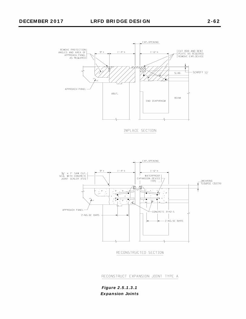
DECEMBER 2017 LRFD BRIDGE DESIGN 2-62
Figure 2.5.1.3.1 Expansion Joints

DECEMBER 2017 LRFD BRIDGE DESIGN 2-63
Figure 2.5.1.3.2 Expansion Joints

DECEMBER 2017 LRFD BRIDGE DESIGN 2-64
Figure 2.5.1.3.3 Expansion Joints
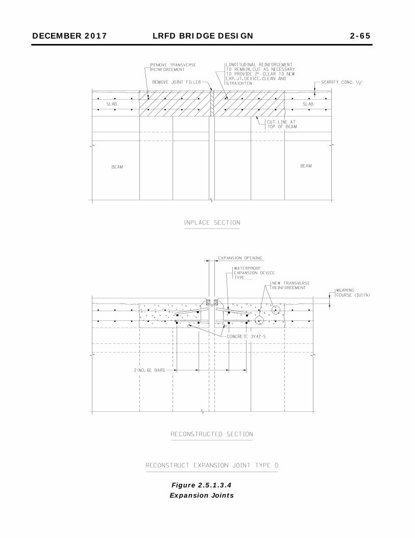
DECEMBER 2017 LRFD BRIDGE DESIGN 2-65
Figure 2.5.1.3.4 Expansion Joints
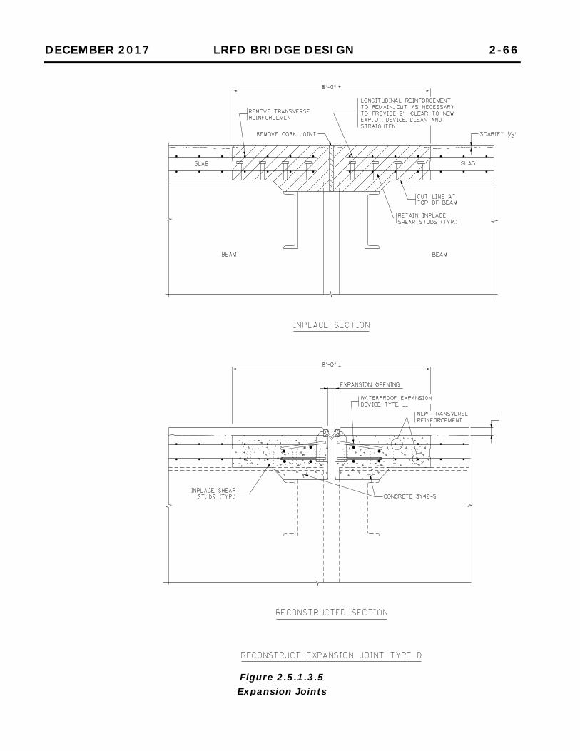
DECEMBER 2017 LRFD BRIDGE DESIGN 2-66
Figure 2.5.1.3.5 Expansion Joints

DECEMBER 2017 LRFD BRIDGE DESIGN 2-67
Figure 2.5.1.3.6 Expansion Joints

DECEMBER 2017 LRFD BRIDGE DESIGN 2-68
Figure 2.5.1.3.7 Expansion Joints

DECEMBER 2017 LRFD BRIDGE DESIGN 2-69
Figure 2.5.1.3.8 Fixed Joints

DECEMBER 2017 LRFD BRIDGE DESIGN 2-70
Figure 2.5.1.3.9 Fixed Joints

DECEMBER 2017 LRFD BRIDGE DESIGN 2-71
2.5.2 Substructure
2.5.2.1 Abutments
[Future manual content] The following figures show typical details for the repair of abutment paving brackets: Figure 2.5.2.1.1 Repair Paving Bracket Figure 2.5.2.1.2 Reconstruct Paving Bracket Figure 2.5.2.1.3 Reconstruct Paving Bracket and Wall Paving Bracket Repair Pay Items Item No. 2433.603 “Repair Paving Bracket”, Lin. Ft. Item No. 2433.603 “Reconstruct Paving Bracket”, Lin. Ft. Item No. 2433.603 “Reconstruct Paving Bracket and Wall”, Lin. Ft.

DECEMBER 2017 LRFD BRIDGE DESIGN 2-72
Figure 2.5.2.1.1 Paving Brackets

DECEMBER 2017 LRFD BRIDGE DESIGN 2-73
Figure 2.5.2.1.2 Paving Brackets

DECEMBER 2017 LRFD BRIDGE DESIGN 2-74
Figure 2.5.2.1.3 Paving Brackets

DECEMBER 2017 LRFD BRIDGE DESIGN 2-75
2.5.2.2 Piers
2.5.3 Pavement
[Future manual content] The following figures show typical details for pavement joint reconstruction: Figure 2.5.3.1 Reconstruct Pavement Joint Type A Figure 2.5.3.2 Reconstruct Pavement Joint Type B Figure 2.5.3.3 Reconstruct Pavement Joint Type C Figure 2.5.3.4 Reconstruct Pavement Joint Type Special Figure 2.5.3.5 Reconstruct Pavement Joint Type Special Pavement Joint Reconstruction Pay Items Item No. 2433.603 “Reconstruct Pavement Joint, Type ____”, Lin. Ft.
Type A – Approach panel or roadway, remove inplace protection angles and compression seals and recast concrete. (Eliminate Joint.)
Type B – Approach panel, replace inplace joint or crack with concrete sill and 4" relief joint.
Type C – Remove protection angles and replace with roadway joint. Type Special – None of the above or a combination of the above.

DECEMBER 2017 LRFD BRIDGE DESIGN 2-76
Figure 2.5.3.1 Pavement Joints
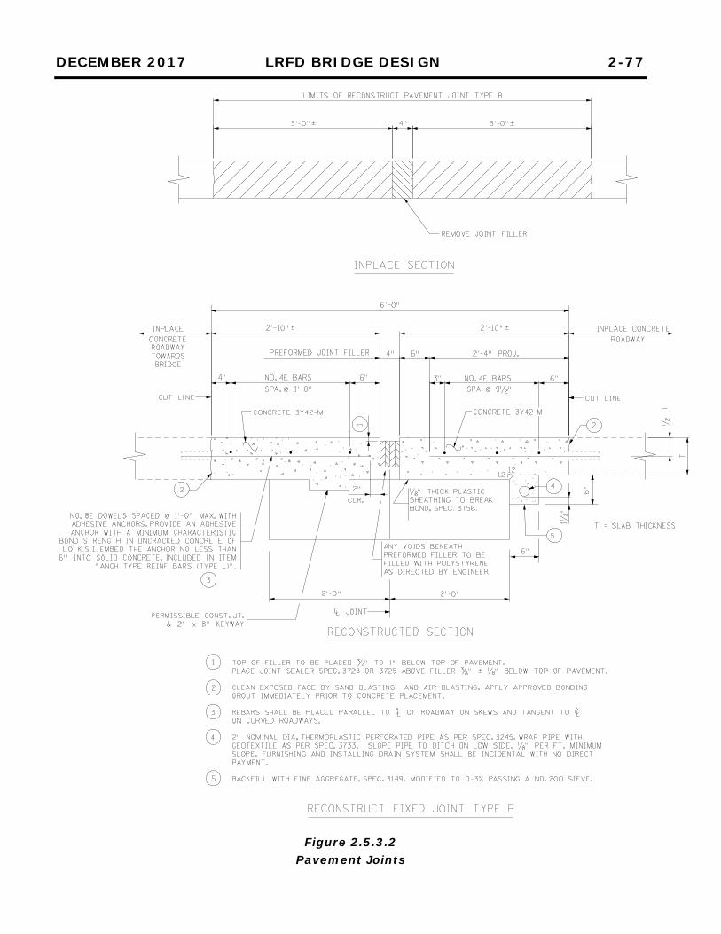
DECEMBER 2017 LRFD BRIDGE DESIGN 2-77
Figure 2.5.3.2 Pavement Joints

DECEMBER 2017 LRFD BRIDGE DESIGN 2-78
Figure 2.5.3.3 Pavement Joints

DECEMBER 2017 LRFD BRIDGE DESIGN 2-79
Figure 2.5.3.4 Pavement Joints

DECEMBER 2017 LRFD BRIDGE DESIGN 2-80
Figure 2.5.3.5 Pavement Joints

DECEMBER 2017 LRFD BRIDGE DESIGN 2-81
2.6 Construction Requirements
MnDOT’s general practices and guidelines for the construction of bridges are presented in MnDOT’s Bridge Construction Manual, which can be accessed from the MnDOT Bridge Office web site. Provide the required submittals and the qualifications of the individuals responsible for the preparation of falsework and other submittals in the contract documents for the project. Falsework and forms are to be designed in accordance with the AASHTO Guide Design Specifications for Bridge Temporary Works. Falsework submittals must meet the requirements of Bridge Special Provision No. SB2018-2401.2. Submittals describing proposed temporary shoring for works adjacent to railroad tracks require approval by the railroad. Provide details of temporary shoring in the plans with consideration of the domestic availability of the sheeting materials. Frequently, showing the location of the sheeting and the minimum required section modulus is sufficient. However, designers should satisfy themselves that adequate clearances have been provided for at least one reasonable shoring scheme for staged construction projects. If more complex details are required, they must be provided in the plans. See Article 11.3.7 of this manual for more guidance.

DECEMBER 2017 LRFD BRIDGE DESIGN 2-82
APPENDIX 2-A BRIDGE TYPE NUMBERS
MINNESOTA BRIDGE TYPE IDENTIFICATION NUMBER (3 characters)
First Digit (Superstructure Material) Second & Third Digits (Bridge Type)
1 Cast-In-Place Concrete 01 Beam Span
2 Cast-In-Place Concrete Continuous 02 Low Truss
3 Steel 03 High Truss
4 Steel Continuous 04 Deck Truss
5 Prestressed Pretensioned or Precast Concrete 05 Thru Girder
6 Prestressed Pretensioned Continuous Concrete 06 Deck Girder
7 Timber 07 Box Girder
8 Masonry 08 Rigid Frame
9 Wrought or Cast Iron 09 Slab Span
O Other 10 Slab Span-Voided
A Aluminum 11 Channel Span
P Prestressed Post-Tensioned 12 Arch
13 Box Culvert
14 Pipe Culvert (Round)
15 Pipe Arch
16 Long Span
17 Tunnel
18 Movable
19 Other
20 Double Tee
21 Quad Tee
22 Bulb Tee
23 Suspension
24 Tied Arch
25 Cable Stay
26 Inverted T
EXAMPLES
BRIDGE TYPE ID NUMBER
Precast Concrete Box Culvert 513
Simple Span Cast-In-Place Concrete Slab 109
Tunnel in Rock 017
Pretensioned Concrete Beam Span 501 approach span
Steel Continuous Beam Span 401 main span
Post-Tensioned Concrete Box Girder P07 Note: A bridge may have different identification numbers for each
span. Identify all span types accordingly.

DECEMBER 2017 LRFD BRIDGE DESIGN 2-83
APPENDIX 2-B STANDARD ABBREVIATIONS
A
AASHTO ......... American Association of State Highway and Transportation Officials
ABT. .............................................. About ABUT. ....................................... Abutment AADT ............... Annual Average Daily Traffic ADTT ................. Average Daily Truck Traffic ALT. .......................................... Alternate APPR. ......................................... Approach APPROX. .... Approximate (or Approximately) ASSY. ....................................... Assembly AZ. ............................................. Azimuth @ ...................................................... At B
B.F. .......................................... Back Face BIT. ........................................ Bituminous B.M. ...................................... Bench Mark BM .................................................. Beam BOT. ............................................ Bottom BR. ................................................ Bridge BRG. ............................................ Bearing BTWN. ........................................ Between C
C & G ................................ Curb and Gutter C-I-P .................................... Cast-In-Place CL ........................................... Centerline CL. (or CLR.) ..................................... Clear C.M.P. ...................... Corrugated Metal Pipe COL. ............................................ Column COMP. ...................................... Composite CONC. ........................................ Concrete CONST. ................................. Construction CONT. ................ Continuous (or Continued) C.S.A.H. ............. County State Aid Highway CU. ................................................. Cubic CULV. ........................................... Culvert
D D.C. ................................ Degree of Curve DET. ............................................... Detail D.H.V. ..................... Design Hourly Volume D.H.W. .......................... Design High Water DIA. .......................................... Diameter DIAPH. ..................................... Diaphragm DL .......................................... Dead Load DWL. ............................................. Dowel E
E. ................................................... East E.B.L. .......................... East Bound Lane(s) E.F. .......................................... Each Face EA. .................................................. Each ELEV. (or EL.) .............................. Elevation EMBED. .................................. Embedment ENGR. ......................................... Engineer EQ. ................................................. Equal EXP. ......................................... Expansion F
F. .......................................... Fahrenheit F.B.M. ......................... Foot Board Measure F.F. ......................................... Front Face F.L. ............................................. Flowline FIN. ............................................ Finished FIX ................................................. Fixed FT. ...................................... Foot (or Feet) FTG. ............................................ Footing G
G1 .......................................... Grade One G2 .......................................... Grade Two GA. ................................................. Gage
DECEMBER 2017 LRFD BRIDGE DESIGN 2-84
APPENDIX 2-B (Continued) STANDARD ABBREVIATIONS
H
HCAADT .............. Heavy Commercial Annual Average Daily Traffic
H.W. ....................................... High Water HORIZ. ..................................... Horizontal HWY. .......................................... Highway I
INPL. ........................................... Inplace I.D. .................................. Inside Diameter J
JCT. ............................................ Junction JT. ................................................... Joint K
KWY. ........................................... Keyway L
L. ................................... Length of Curve LL ............................................ Live Load L.W. ........................................ Low Water LB. ................................................ Pound LIN. ............................................... Linear LT. ................................................... Left LONG. (or LONGIT.) .................. Longitudinal M
m .................................................. Meter mm ........................................... Millimeter M.B.M. ...................... Thousand Board Feet M.L. .......................................... Main Line M.O. ................................ Maximum Offset MAX. ......................................... Maximum MIN. .......................................... Minimum MISC. .................................. Miscellaneous
N N. (or NO.) ....................................... North N.B.L. ........................ North Bound Lane(s) NO. ............................................. Number O
O.D. ............................... Outside Diameter P
P.C. ............................... Point of curvature P.C.C. .................. Point of compound Curve P.G. ...................................... Profile Grade P.I. ............................. Point of Intersection P.O.C. ................................ Point on Curve P.O.T. ............................. Point on Tangent P.S.I. ..................... Pounds per Square Inch P.T. ............................... Point of Tangency PED. ........................................ Pedestrian PL .................................................. Plate PRESTR. .................................. Prestressed PROJ. ...................... Project (or Projection) PROV. ........................................ Provision PT. .................................................. Point R
R. ............................................... Radius R.O.W. .................................. Right of Way R.R. ............................................ Railroad R.S.C. .......................... Rigid Steel Conduit RDWY. ....................................... Roadway REINF. ...... Reinforced (or Reinforcing/ment) REQ'D ......................................... Required REV. ............................................ Revised RT. ................................................. Right S
S. (or SO.) ....................................... South S.B.L. ........................ South Bound Lane(s) SEC. ............................................ Section SDWK. ....................................... Sidewalk SHLDR. ...................................... Shoulder

DECEMBER 2017 LRFD BRIDGE DESIGN 2-85
APPENDIX 2-B (Continued) STANDARD ABBREVIATIONS
S (cont.)
SHT. ...............................................Sheet SP. (or SPS.) .................................. Spaces SPA. ............................................ Spaced SPEC. .................. Special (or Specification) SPG. ............................................ Spacing SQ. ............................................... Square STA. ............................................. Station STD. .......................................... Standard STIFF. ......................................... Stiffener STL. ............................................... Steel STR. (or STRUC.) ......................... Structure SUBGR. ..................................... Subgrade SUPER. .............................. Superelevation SUPERST. ........................... Superstructure SYM. ..................................... Symmetrical T
T & B ................................ Top and Bottom T.H. ................................... Trunk Highway T.T.C. ............................. Tangent to Curve TAN. ........................................... Tangent TWP. .......................................... Township TYP. .............................................. Typical V
V.C. .................................... Vertical Curve V.P.C. ................ Vertical Point of Curvature V.P.I. .............. Vertical Point of Intersection V.P.T. ................. Vertical Point of Tangency VAR. .............................................. Varies VERT. .......................................... Vertical W
W. ................................................... West W.B.L. ........................ West Bound Lane(s) W.C. ................................. Wearing Course W.P. ................................... Working Point W.W. ......................................... Wingwall
Y YD. .................................................. Yard

DECEMBER 2017 LRFD BRIDGE DESIGN 2-86
APPENDIX 2-C STANDARD PLAN NOTES
Use standard notes that are relevant to the project. Text found in brackets [ ] next to a standard note provides guidance on its use and should not be included in the plan.
A. DESIGN DATA AND PROJECTED TRAFFIC VOLUMES
a. NEW BRIDGES OTHER THAN CONCRETE BOX CULVERTS DESIGNED IN ACCORDANCE WITH 20__ AASHTO LRFD BRIDGE DESIGN SPECIFICATIONS HL-93 LIVE LOAD DEAD LOAD INCLUDES 20 POUNDS PER SQUARE FOOT ALLOWANCE FOR FUTURE WEARING COURSE MODIFICATIONS
[Use on all roadway bridge projects. Insert current year of specifications.] DESIGNED IN ACCORDANCE WITH 20__ AND CURRENT INTERIM AASHTO LRFD GUIDE SPECIFICATIONS FOR THE DESIGN OF PEDESTRIAN BRIDGES PEDESTRIAN LIVE LOAD = 0.090 KSF __*__ TRUCK VEHICULAR LIVE LOAD
[Use on all pedestrian bridge projects. Insert current year of specifications.] [* Insert “H-5” for deck widths between parapet/curb faces 10 ft. For deck widths between parapet/curb faces > 10 ft., insert “H-10”]
MATERIAL DESIGN PROPERTIES: REINFORCED CONCRETE:
f’c = 4 KSI CONCRETE fy = 60 KSI PLAIN AND EPOXY COATED BARS fy = 75 KSI STAINLESS STEEL BARS n = 8 FOR REINFORCEMENT BARS
[Use on all projects, except do not include stainless steel when it is used only to tie approach panels to abutments.]
PRETENSIONED CONCRETE:
f’c = __ KSI CONCRETE fpu = 270 KSI LOW RELAXATION STRANDS n = 1 FOR PRETENSIONING STRANDS 0.75 fpu FOR INITIAL PRESTRESS
[Coordinate f’c with beam detail sheet. Use on bridges with pretensioned beams.]

DECEMBER 2017 LRFD BRIDGE DESIGN 2-87
APPENDIX 2-C (Continued) STANDARD PLAN NOTES
Use standard notes that are relevant to the project. Text found in brackets [ ] next to a standard note provides guidance on its use and should not be included in the plan.
A. DESIGN DATA AND PROJECTED TRAFFIC VOLUMES (CONT’D)
a. NEW BRIDGES OTHER THAN CONCRETE BOX CULVERTS (CONT’D) POST-TENSIONED CONCRETE:
f’c = __ KSI CONCRETE fpu = 270 KSI LOW RELAXATION STRANDS n = 1 FOR POST-TENSIONING STRANDS 0.75 fpu FOR INITIAL PRESTRESS TOP OF DECK DESIGNED FOR ZERO TENSION UNDER SERVICE LOADS
[Use as required, e.g. post-tensioned slabs or box girders. Insert concrete strength.]
STRUCTURAL STEEL:
Fy = 36 KSI STRUCTURAL STEEL SPEC. 3306 (PAINTED) Fy = 50 KSI STRUCTURAL STEEL SPEC. 3309 (PAINTED) Fy = 50 KSI STRUCTURAL STEEL SPEC. 3310 (PAINTED) Fy = 70 KSI STRUCTURAL STEEL SPEC. 3317 (HIGH PERFORMANCE)
(PAINTED) [Use as required on bridges with steel components. Include description within parentheses as needed.]
WOOD:
Fbo = ____ KSI PILE CAPS Fbo = ____ KSI SAWN STRINGERS AND TIMBER RAILS Fbo = ____ KSI GLUED LAMINATED TIMBER RAILS Fbo = ____ KSI GLUED LAMINATED STRINGERS Fbo = ____ KSI GLUED LAMINATED DECK PANELS Fbo = ____ KSI NAIL LAMINATED DECK PANELS Fbo = ____ KSI RAIL POSTS Fbo = ____ KSI ALL OTHER WOOD
[Use as required on bridges with wood components. Insert reference design values.]
DESIGN SPEED:
OVER = _______ MPH [Use on all projects. Insert speed.]
UNDER = _______ MPH [Use as required. Insert speed.]

DECEMBER 2017 LRFD BRIDGE DESIGN 2-88
APPENDIX 2-C (Continued) STANDARD PLAN NOTES
Use standard notes that are relevant to the project. Text found in brackets [ ] next to a standard note provides guidance on its use and should not be included in the plan.
A. DESIGN DATA AND PROJECTED TRAFFIC VOLUMES (CONT’D)
a. NEW BRIDGES OTHER THAN CONCRETE BOX CULVERTS (CONT’D) DECK AREA = __________ SQUARE FEET
[Use on all projects. Insert area based on dimensions from coping to coping and begin bridge to end bridge.]
_____ PROJECTED AADT FOR YEAR 20__
[Use when provided on the Preliminary Plan. Insert appropriate values.] 20__ PROJECTED TRAFFIC VOLUMES ROADWAY OVER ROADWAY UNDER ______ AADT _______ ______ DHV _______ ______ HCAADT _______
[Use when provided on the Preliminary Plan. Insert appropriate values. Note that HCAADT is Heavy Commercial Annual Average Daily Traffic, which can be considered equivalent to the Average Daily Truck Traffic (ADTT) used by the AASHTO LRFD Bridge Design Specifications.]
HL-93 LRFR BRIDGE OPERATING RATING FACTOR RF = ______
[Use on all projects. Insert rating factor.]

DECEMBER 2017 LRFD BRIDGE DESIGN 2-89
APPENDIX 2-C (Continued) STANDARD PLAN NOTES
Use standard notes that are relevant to the project. Text found in brackets [ ] next to a standard note provides guidance on its use and should not be included in the plan. A. DESIGN DATA AND PROJECTED TRAFFIC VOLUMES (CONT’D)
b. PRECAST CONCRETE BOX CULVERTS DESIGNED IN ACCORDANCE WITH ____ AASHTO LRFD BRIDGE DESIGN SPECIFICATIONS
[For standard precast concrete box culvert designs, insert date of specifications that standards are based on, which can be found at the top of Bridge Standard Plans Figure 5-395.100(A) Precast Concrete Box Culvert - Basis of Design. For non-standard designs, insert current year of specifications.]
HL-93 LIVE LOAD BARREL SPAN = ______ BARREL RISE = ______ BARREL LENGTH = _______ EST. MIN. FILL DEPTH A = ______ EST. MAX. FILL DEPTH B = ______ SKEW ANGLE = ___˚ ___’ ___”
[Use on all precast concrete box culvert projects. Insert appropriate values. For estimated min. and max. fill depths, also show A and B in the box culvert elevation view to depict the min. and max. fill heights at the outside edge of the roadway shoulder.]
DESIGN SPEED = ___ MPH AADT = _____
[Use on non-trunk highway precast box culvert projects.] MATERIAL DESIGN PROPERTIES:
PRECAST REINFORCED CONCRETE: f’c = __ KSI CONCRETE fy = 65 KSI WELDED WIRE REINFORCEMENT fy = 60 KSI REINFORCEMENT BARS
[Use on all precast concrete box culvert projects. Insert concrete strength.]
HL-93 LRFR BRIDGE OPERATING RATING FACTOR RF = ______
[Use on all precast concrete box culvert projects where the box culvert has been assigned a bridge number. For standard designs, insert 1.3 rating factor. For non-standard designs, insert calculated rating factor.]

DECEMBER 2017 LRFD BRIDGE DESIGN 2-90
APPENDIX 2-C (Continued) STANDARD PLAN NOTES
Use standard notes that are relevant to the project. Text found in brackets [ ] next to a standard note provides guidance on its use and should not be included in the plan. B. CONSTRUCTION NOTES
THE 20__ EDITION OF THE MINNESOTA DEPARTMENT OF TRANSPORTATION “STANDARD SPECIFICATIONS FOR CONSTRUCTION” SHALL GOVERN.
[Use on all projects. Insert current date of specifications.]
SEE SPECIAL PROVISIONS FOR ALL XXXX.6XX SERIES PAY ITEMS FOR ADDITIONAL REQUIREMENTS.
[Use on all projects.]
THE BAR SIZES SHOWN IN THIS PLAN ARE IN U.S. CUSTOMARY DESIGNATIONS. [Use on all projects.]
BARS MARKED WITH THE SUFFIX “E” SHALL BE EPOXY COATED IN ACCORDANCE WITH SPEC. 3301.
[Use on all projects.] BARS MARKED WITH THE SUFFIX “S” SHALL BE STAINLESS STEEL IN ACCORDANCE WITH THE SPECIAL PROVISIONS.
[Use as required.] THE SUBSURFACE UTILITY INFORMATION IN THIS PLAN IS UTILITY QUALITY LEVEL ___. THIS UTILITY QUALITY LEVEL WAS DETERMINED ACCORDING TO THE GUIDELINES OF CI/ASCE 38-02, ENTITLED "STANDARD GUIDELINES FOR THE COLLECTION AND DEPICTION OF EXISTING SUBSURFACE UTILITY DATA".
[Use on all projects. Insert quality level shown in Preliminary Bridge Plan. When unknown, the default level is “D”, which is the lowest level.]
THE PILE LOADS SHOWN IN THE PLANS AND THE CORRESPONDING NOMINAL PILE BEARING RESISTANCE (Rn) WERE COMPUTED USING LRFD METHODOLOGY. PILE BEARING RESISTANCE DETERMINED IN THE FIELD SHALL INCORPORATE THE METHODS AND/OR FORMULAS DESCRIBED IN THE SPECIAL PROVISIONS.
[Use on all plans involving CIP or H piles.]

DECEMBER 2017 LRFD BRIDGE DESIGN 2-91
APPENDIX 2-C (Continued) STANDARD PLAN NOTES
Use standard notes that are relevant to the project. Text found in brackets [ ] next to a standard note provides guidance on its use and should not be included in the plan.
B. CONSTRUCTION NOTES (CONT’D)
THE GIRDERS HAVE BEEN DESIGNED AND DETAILED WITHOUT DIAPHRAGMS. THE CONTRACTOR’S ENGINEER SHALL DESIGN, AND THE CONTRACTOR SHALL CONSTRUCT A TEMPORARY BRACING SYSTEM AND/OR A DECK FALSEWORK/FORMWORK SYSTEM. THE SYSTEM SHALL PROVIDE LATERAL AND ROTATIONAL STABILITY OF THE GIRDERS TO RESIST UNSYMMETRICAL CONCRETE AND CONSTRUCTION LOADS UNTIL THE DECK CONCRETE HAS ATTAINED A MINIMUM STRENGTH OF 2800 PSI.
[Use on all plans with pretensioned RB shapes or 27M I-beams where diaphragms are not used.]
INSTALL SETTLEMENT PLATE BEHIND EACH ABUTMENT. SEE GRADING PLANS. [Use when specified in Foundation Recommendations.]
CONSTRUCTION OF EACH ABUTMENT SHALL NOT BE STARTED UNTIL THE APPROACH FILL AT THAT ABUTMENT HAS BEEN CONSTRUCTED TO THE FULL HEIGHT AND CROSS SECTION (AND ALLOWED TO SETTLE FOR _____ DAYS).
[Use when specified in Foundation Recommendations. Insert waiting period if required.]
C. SIGNATURE BLOCK APPROVED _________________________________
STATE BRIDGE ENGINEER DATE ____________
[Use on all projects. Provide signature line in the title block on the General Plan and Elevation sheet.]
D. DRAINAGE AND EROSION CONTROL RESTORE SIDE DITCHES AFTER PLACEMENT OF SLOPE PAVING TO PROVIDE DRAINAGE AS DIRECTED BY THE ENGINEER. RESTORATION COSTS SHALL BE INCLUDED IN PRICE BID FOR STRUCTURE EXCAVATION.
[Use this note on railroad underpasses.] _______________ PIPE TO BE PLACED UNDER GRADING PORTION OF CONTRACT.
[Use this note with combined Bridge and Roadway contracts only. Modify the notes to suit job requirements. Insert pipe description.]

DECEMBER 2017 LRFD BRIDGE DESIGN 2-92
APPENDIX 2-C (Continued) STANDARD PLAN NOTES
Use standard notes that are relevant to the project. Text found in brackets [ ] next to a standard note provides guidance on its use and should not be included in the plan.
E. EXCAVATION AND EARTHWORK
QUANTITY OF STRUCTURE EXCAVATION FOR PAYMENT IS COMPUTED WITH THE ELEVATION SHOWN FOR EACH SUBSTRUCTURE UNIT AS THE UPPER LIMIT. EXCAVATION ABOVE THESE ELEVATIONS WILL BE PAID FOR UNDER THE GRADING PORTION OF THE CONTRACT.
[Use this note when rock and other type excavation will be encountered. Do not use this note when lump sum payment for structure excavation is used. Specify an elevation for top of exposed or buried rock and add the note “Average elevations of top of rock are assumed for estimated plan quantities.”]
THE LOWER LIMITS OF STRUCTURE EXCAVATION CLASS E SHALL BE THE SAME AS THE UPPER LIMITS OF STRUCTURE EXCAVATION CLASS WE EXCEPT FOR ROCK EXCAVATIONS.
[Use as required.] ROADWAY (OR CHANNEL) EXCAVATION WILL BE MADE BY OTHERS IN ADVANCE OF BRIDGE CONSTRUCTION.
[Not applicable on combined project.] FOOTINGS SHALL BE KEYED INTO SOUND BEDROCK AS DIRECTED BY THE ENGINEER. TOP OF FOOTINGS SHALL HAVE A MINIMUM OF 1'-0" COVER.
[Use as required.] CONTRACTOR SHALL DRESS SLOPES AND PLACE FILTER MATERIALS AND RIPRAP IN APPROXIMATE AREAS AS DIRECTED BY THE ENGINEER.
[Use as required.]
SUBCUT FOOTING A MINIMUM OF 2’-0” AND PLACE AGGREGATE BACKFILL (CONFORMING TO SPEC. 3149.2.E) PER SPEC. 2451 AS SHOWN. COMPACT TO 100% MAXIMUM DENSITY IN ACCORDANCE WITH SPEC 2105.3.F.1. SEE SPECIAL PROVISIONS.
[Use when a subcut for a spread footing is required.]

DECEMBER 2017 LRFD BRIDGE DESIGN 2-93
APPENDIX 2-C (Continued) STANDARD PLAN NOTES
Use standard notes that are relevant to the project. Text found in brackets [ ] next to a standard note provides guidance on its use and should not be included in the plan.
F. REINFORCEMENT
SPIRAL DATA OUTSIDE DIAMETER _______ HEIGHT _______ PITCH ________ SPIRAL ROD SIZE, PLAIN ROUND ________ WEIGHT, EACH _______
[Use for round columns that contain spiral reinforcement. Insert appropriate data.]
OUTSIDE DIAMETER OF DOWEL CIRCLE TO BE 21/4" LESS THAN INSIDE DIAMETER OF SPIRAL.
[Use for round columns that contain spiral reinforcement. Where No. 10 and larger sized column vertical bars are used, increase the 21/4" dimension where required to provide for a proper fit.]

DECEMBER 2017 LRFD BRIDGE DESIGN 2-94
APPENDIX 2-C (Continued) STANDARD PLAN NOTES
Use standard notes that are relevant to the project. Text found in brackets [ ] next to a standard note provides guidance on its use and should not be included in the plan.
G. FOUNDATIONS
a. SPREAD FOOTINGS ON SOIL
__________ ABUTMENT SPREAD FOOTING LOAD DATA
PIER _______
SPREAD FOOTING LOAD DATA
* ____†____ DESIGN BEARING PRESSURE
TONS/SQ FT * ____†____ DESIGN BEARING
PRESSURE TONS/SQ FT
EFFECTIVE WIDTH B' FT EFFECTIVE WIDTH B'
(PERPENDICULAR TO PIER) FT
____†____ BEARING RESISTANCE b·qn
TONS/SQ FT EFFECTIVE LENGTH L' (PARALLEL TO PIER)
FT
* BASED ON __________ LOAD COMBINATION. ____†____ BEARING RESISTANCE
B·qn TONS/SQ FT
* BASED ON __________ LOAD COMBINATION.
[Use for spread footing foundations on soil. Insert data. Round loads to nearest 0.1 tons/sq ft.] [ † Insert “SERVICE” or “FACTORED” based on governing limit state.]
b. SPREAD FOOTINGS ON ROCK
__________ ABUTMENT SPREAD FOOTING LOAD DATA
PIER _______
SPREAD FOOTING LOAD DATA
* MAX FACTORED TRAPEZOIDAL DESIGN BEARING PRESSURE
TONS/SQ FT * FTG CORNER 1 MAXIMUM FACTORED TRAPEZOIDAL
DESIGN BEARING PRESSURE TONS/SQ FT
* MIN FACTORED TRAPEZOIDAL DESIGN BEARING PRESSURE
TONS/SQ FT * FTG CORNER 2 FACTORED
TRAPEZOIDAL DESIGN BEARING PRESSURE
TONS/SQ FT
FACTORED BEARING RESISTANCE b·qn
TONS/SQ FT * FTG CORNER 3 FACTORED
TRAPEZOIDAL DESIGN BEARING PRESSURE
TONS/SQ FT
* BASED ON __________ LOAD COMBINATION.
* FTG CORNER 4 FACTORED TRAPEZOIDAL
DESIGN BEARING PRESSURE TONS/SQ FT
FACTORED BEARING RESISTANCE
b·qn TONS/SQ FT
* BASED ON __________ LOAD COMBINATION.
[Use for spread footing foundations on rock. Define footing corners in bridge plan. Insert data. Round loads to nearest 0.1 tons/sq. ft.]

DECEMBER 2017 LRFD BRIDGE DESIGN 2-95
APPENDIX 2-C (Continued) STANDARD PLAN NOTES
Use standard notes that are relevant to the project. Text found in brackets [ ] next to a standard note provides guidance on its use and should not be included in the plan.
G. FOUNDATIONS (CONT’D)
c. LOADS FOR PILES
__________ ABUTMENT COMPUTED PILE LOAD – TONS/PILE
PIER _______
COMPUTED PILE LOAD – TONS/PILE
FACTORED DEAD LOAD + EARTH PRESSURE
FACTORED DEAD LOAD
FACTORED LIVE LOAD FACTORED LIVE LOAD
* FACTORED DESIGN LOAD FACTORED OVERTURNING
* BASED ON __________ LOAD COMBINATION. * FACTORED DESIGN LOAD
* BASED ON __________ LOAD COMBINATION.
[Use for pile foundations. Insert data. Round loads to nearest 0.1 tons/pile.]
d. ADDITIONAL LOAD TABLE FOR PILES WHERE DOWNDRAG OCCURS
__________ ABUTMENT COMPUTED PILE LOAD – TONS/PILE
PIER _______
COMPUTED PILE LOAD – TONS/PILE
FACTORED DEAD LOAD + EARTH PRESSURE
FACTORED DEAD LOAD
FACTORED DOWNDRAG FACTORED OVERTURNING
*** FACTORED DEAD LOAD + EARTH PRESSURE + DOWNDRAG
FACTORED DOWNDRAG
*** BASED ON __________ LOAD COMBINATION, NOT INCLUDING TRANSIENT LOADS. ONLY USED FOR COMPARISON WITH FACTORED STRUCTURAL RESISTANCE. NOT TO BE USED FOR DRIVING.
*** FACTORED DEAD LOAD + OVERTURNING + DOWNDRAG
*** BASED ON __________ LOAD COMBINATION, NOT INCLUDING TRANSIENT LOADS. ONLY USED FOR COMPARISON WITH FACTORED STRUCTURAL RESISTANCE. NOT TO BE USED FOR DRIVING.
[Use for pile foundations where downdrag occurs. Use this table in addition to the standard load table shown above in c. Insert data. Round loads to nearest 0.1 tons/pile.]

DECEMBER 2017 LRFD BRIDGE DESIGN 2-96
APPENDIX 2-C (Continued) STANDARD PLAN NOTES
Use standard notes that are relevant to the project. Text found in brackets [ ] next to a standard note provides guidance on its use and should not be included in the plan.
G. FOUNDATIONS (CONT’D)
e. H-PILE RESISTANCE
__________ ABUTMENT REQUIRED NOMINAL PILE BEARING
RESISTANCE FOR H-PILES Rn – TONS/PILE
PIER _______ REQUIRED NOMINAL PILE BEARING
RESISTANCE FOR H-PILES Rn – TONS/PILE
FIELD CONTROL METHOD dyn ** Rn FIELD CONTROL METHOD dyn ** Rn
MNDOT PILE FORMULA 2012 (MPF12)
R 20WxH1000
x log10S
0.60
MNDOT PILE FORMULA 2012 (MPF12)
R 20WxH1000
x log10S
0.60
PDA 0.65 PDA 0.65
** Rn = (FACTORED DESIGN LOAD) / dyn ** Rn = (FACTORED DESIGN LOAD) / dyn
[Use for H-pile foundations. Insert data. Round loads to nearest 0.1 tons/pile.]
f. CIP CONCRETE PILE RESISTANCE
__________ ABUTMENT REQUIRED NOMINAL PILE BEARING
RESISTANCE FOR CIP PILES Rn – TONS/PILE
PIER _______ REQUIRED NOMINAL PILE BEARING
RESISTANCE FOR CIP PILES Rn – TONS/PILE
FIELD CONTROL METHOD dyn ** Rn FIELD CONTROL METHOD dyn ** Rn
MNDOT PILE FORMULA 2012
(MPF12)
R 20WxH1000
x log10S
0.50
MNDOT PILE FORMULA 2012 (MPF12)
R 20WxH1000
x log10S
0.50
PDA 0.65 PDA 0.65
** Rn = (FACTORED DESIGN LOAD) / dyn ** Rn = (FACTORED DESIGN LOAD) / dyn
[Use for cast-in-place concrete pile foundations. Insert data. Round loads to nearest 0.1 tons/pile.]
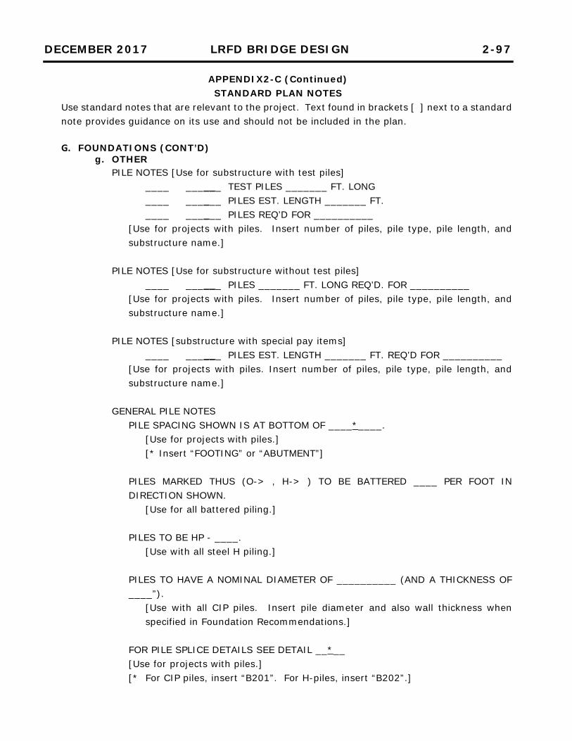
DECEMBER 2017 LRFD BRIDGE DESIGN 2-97
APPENDIX2-C (Continued) STANDARD PLAN NOTES
Use standard notes that are relevant to the project. Text found in brackets [ ] next to a standard note provides guidance on its use and should not be included in the plan.
G. FOUNDATIONS (CONT’D)
g. OTHER
PILE NOTES [Use for substructure with test piles] ____ ______ TEST PILES _______ FT. LONG ____ ______ PILES EST. LENGTH _______ FT. ____ ______ PILES REQ’D FOR __________
[Use for projects with piles. Insert number of piles, pile type, pile length, and substructure name.]
PILE NOTES [Use for substructure without test piles]
____ ______ PILES _______ FT. LONG REQ’D. FOR __________ [Use for projects with piles. Insert number of piles, pile type, pile length, and substructure name.]
PILE NOTES [substructure with special pay items]
____ ______ PILES EST. LENGTH _______ FT. REQ’D FOR __________ [Use for projects with piles. Insert number of piles, pile type, pile length, and substructure name.]
GENERAL PILE NOTES PILE SPACING SHOWN IS AT BOTTOM OF ____*____.
[Use for projects with piles.] [* Insert “FOOTING” or “ABUTMENT”]
PILES MARKED THUS (O-> , H-> ) TO BE BATTERED ____ PER FOOT IN DIRECTION SHOWN.
[Use for all battered piling.]
PILES TO BE HP - ____. [Use with all steel H piling.]
PILES TO HAVE A NOMINAL DIAMETER OF __________ (AND A THICKNESS OF ____”).
[Use with all CIP piles. Insert pile diameter and also wall thickness when specified in Foundation Recommendations.]
FOR PILE SPLICE DETAILS SEE DETAIL __*__ [Use for projects with piles.] [* For CIP piles, insert “B201”. For H-piles, insert “B202”.]
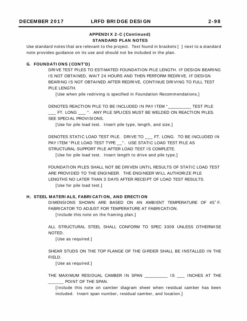
DECEMBER 2017 LRFD BRIDGE DESIGN 2-98
APPENDIX 2-C (Continued) STANDARD PLAN NOTES
Use standard notes that are relevant to the project. Text found in brackets [ ] next to a standard note provides guidance on its use and should not be included in the plan.
G. FOUNDATIONS (CONT’D)
DRIVE TEST PILES TO ESTIMATED FOUNDATION PILE LENGTH. IF DESIGN BEARING IS NOT OBTAINED, WAIT 24 HOURS AND THEN PERFORM REDRIVE. IF DESIGN BEARING IS NOT OBTAINED AFTER REDRIVE, CONTINUE DRIVING TO FULL TEST PILE LENGTH.
[Use when pile redriving is specified in Foundation Recommendations.] DENOTES REACTION PILE TO BE INCLUDED IN PAY ITEM “_________ TEST PILE ___ FT. LONG ___ “. ANY PILE SPLICES MUST BE WELDED ON REACTION PILES. SEE SPECIAL PROVISIONS.
[Use for pile load test. Insert pile type, length, and size.] DENOTES STATIC LOAD TEST PILE. DRIVE TO ___ FT. LONG. TO BE INCLUDED IN PAY ITEM “PILE LOAD TEST TYPE __”. USE STATIC LOAD TEST PILE AS STRUCTURAL SUPPORT PILE AFTER LOAD TEST IS COMPLETE.
[Use for pile load test. Insert length to drive and pile type.] FOUNDATION PILES SHALL NOT BE DRIVEN UNTIL RESULTS OF STATIC LOAD TEST ARE PROVIDED TO THE ENGINEER. THE ENGINEER WILL AUTHORIZE PILE LENGTHS NO LATER THAN 3 DAYS AFTER RECEIPT OF LOAD TEST RESULTS.
[Use for pile load test.]
H. STEEL MATERIALS, FABRICATION, AND ERECTION DIMENSIONS SHOWN ARE BASED ON AN AMBIENT TEMPERATURE OF 45˚F. FABRICATOR TO ADJUST FOR TEMPERATURE AT FABRICATION.
[Include this note on the framing plan.]
ALL STRUCTURAL STEEL SHALL CONFORM TO SPEC 3309 UNLESS OTHERWISE NOTED.
[Use as required.] SHEAR STUDS ON THE TOP FLANGE OF THE GIRDER SHALL BE INSTALLED IN THE FIELD.
[Use as required.] THE MAXIMUM RESIDUAL CAMBER IN SPAN _________ IS ___ INCHES AT THE ______ POINT OF THE SPAN.
[Include this note on camber diagram sheet when residual camber has been included. Insert span number, residual camber, and location.]

DECEMBER 2017 LRFD BRIDGE DESIGN 2-99
APPENDIX 2-C (Continued) STANDARD PLAN NOTES
Use standard notes that are relevant to the project. Text found in brackets [ ] next to a standard note provides guidance on its use and should not be included in the plan.
H. STEEL MATERIALS, FABRICATION, AND ERECTION (CONT’D)
THERE IS NO RESIDUAL CAMBER IN THESE BEAMS. [Include this note on camber diagram sheet when residual camber has not been included.]
CHORD LINE IN CAMBER DIAGRAM IS A STRAIGHT LINE FROM END TO END OF BEAM SEGMENT AT ________*_________.
[Include this note on camber diagram sheet of steel girder bridges] [* For plate girders, insert “TOP OF BEAM WEB”. For rolled beams, insert “BOTTOM OF TOP FLANGE”.]
CAMBER DIAGRAM SHOWN IS FOR BEAMS IN UNLOADED POSITION AND PROVIDES FOR ALL DEAD LOAD DEFLECTIONS (AND RESIDUAL CAMBER).
[Include this note on camber diagram sheet of steel girder bridges. Include residual camber portion of note when used in the beams.]
LINE ASSEMBLY PER SPEC. 2471 WILL BE REQUIRED FOR BEAM SPLICES. THE SECTION TO BE LINE ASSEMBLED SHALL BE FROM ________ TO __________ .
[Use on bridges where girders were designed using line girder analysis. Check with the Structural Metals Unit; Abutment to abutment if < 300 ft. Three adjacent points of support if > 300 ft.]
FULL ASSEMBLY WILL BE REQUIRED PER SPEC. 2471. [The use of full assembly should be considered for extremely complicated curved, superelevated structures (i.e. grid or 3D analysis used for design). Check with the Structural Metals Unit and Fabrication Methods Unit.]
PRIOR TO POURING DECK, SNUG TIGHTEN ONLY BOLTS IN THE END DIAPHRAGMS. AFTER POURING ALL DECK CONCRETE, FULLY TIGHTEN END DIAPHRAGM BOLTS.
[Use on all skewed steel bridges.]
PROVIDE OVERSIZED HOLES IN END DIAPHRAGM CONNECTIONS. [Use on all skewed steel bridges.]
DETAIL AND FABRICATE STEEL MEMBERS FOR A NO-LOAD FIT.
[Use on all steel girder bridges.]

DECEMBER 2017 LRFD BRIDGE DESIGN 2-100
APPENDIX 2-C (Continued) STANDARD PLAN NOTES
Use standard notes that are relevant to the project. Text found in brackets [ ] next to a standard note provides guidance on its use and should not be included in the plan.
H. STEEL MATERIALS, FABRICATION, AND ERECTION (CONT’D)
FOR WELDED FLANGE SPLICES, SEE SPEC 2471.3.F.1.a. [Use drawings instead of note only if different than AASHTO/AWS D1.5 Bridge Welding Code 2010 Fig. 2.7 or 2.8.]
WEB PLATES SHALL BE FURNISHED IN AVAILABLE MILL LENGTHS AND WIDTHS WITH A MINIMUM NUMBER OF WEB SPLICES. LOCATION OF SPLICES SHALL BE SUBJECT TO THE APPROVAL OF THE ENGINEER AND SHALL BE A MINIMUM OF 1'-0" FROM STIFFENERS OR FLANGE SPLICES.
[Use on all steel plate girder bridges.]
BEARING STIFFENERS AT ABUTMENTS SHALL BE VERTICAL. BEARING STIFFENERS AT PIERS AND DIAPHRAGM CONNECTION STIFFENERS SHALL BE PERPENDICULAR TO FLANGE. ENDS OF BEAMS SHALL BE VERTICAL.
[Use for grades greater than 3% on plate girder bridges or skews greater than 20°.]
BEARING STIFFENERS, DIAPHRAGM CONNECTION STIFFENERS, AND ENDS OF BEAMS SHALL BE PERPENDICULAR TO FLANGE.
[Use for rolled beams or grades 3%.] ROWS OF SHEAR CONNECTORS SHALL BE ALIGNED PARALLEL TO THE TRANSVERSE SLAB REINFORCEMENT BARS.
[Use on all steel bridges with shear studs.] SHEAR CONNECTORS TO PROJECT A MINIMUM OF 2" INTO DECK STRUCTURAL SLAB. IN NO CASE SHALL SHEAR CONNECTORS PROJECT CLOSER THAN _*_” TO TOP OF DECK STRUCTURAL SLAB. ENGINEER TO FIELD VERIFY BEAM ELEVATION AND AUTHORIZE STUD LENGTH.
[Use on all steel bridges with shear studs.] [*Insert “1” for decks with 2” wearing course. Insert “3” for monolithic decks.]
FLANGE PLATES FOR BEAMS SHALL BE CUT TO PROPER CURVATURE. [Use this note when the minimum radius of curvature requirements of AASHTO LRFD Bridge Construction Specifications, Article 11.4.12.2.2 are not met.]
ALL BOLTED CONNECTIONS SHALL BE MADE WITH 7/8" DIAMETER A325 BOLTS, EXCEPT AS NOTED.
[Use as required.]

DECEMBER 2017 LRFD BRIDGE DESIGN 2-101
APPENDIX 2-C (Continued) STANDARD PLAN NOTES
Use standard notes that are relevant to the project. Text found in brackets [ ] next to a standard note provides guidance on its use and should not be included in the plan.
H. STEEL MATERIALS, FABRICATION, AND ERECTION (CONT’D)
ELEVATIONS SHOWN AT FIELD SPLICES ARE THEORETICAL ELEVATIONS FURNISHED AS A GUIDE FOR ERECTION. ELEVATIONS ARE GIVEN AT TOP OF TOP FLANGE SPLICE PLATE AND INCLUDE DEFLECTIONS FROM WEIGHT OF BEAM AND DIAPHRAGM.
[Use as required.] DEFLECTIONS SHOWN ARE FOR WEIGHT OF SLAB, CONCRETE OVERLAY, ______. NEGATIVE SIGN INDICATES UPLIFT.
[Use as required. Insert barrier, parapet, metal railing, sidewalk, median, etc. as needed. Do not include the weight of steel beams or future wearing course.]
SHEAR CONNECTORS TO BE INCLUDED IN WEIGHT OF STRUCTURAL STEEL (3309) AND CONFORM TO SPEC. 3391.
[Use on all steel bridges with shear studs.]
I. CONCRETE PLACEMENTS REMOVE ALL NON-GALVANIZED AND NON-EPOXY COATED FERROUS METAL, EXCLUDING SHEAR STUDS, TO WITHIN ½” OF THE TOP FLANGE PRIOR TO CASTING THE DECK.
[Use on all deck-on-beam type bridges. Locate note on the Transverse Section Deck Reinforcement sheet in the bridge plan.]
MAKE SAW CUT IN STRUCTURAL SLAB (AND CONCRETE WEARING COURSE) OVER CENTERLINE OF PIERS AS SOON AS THE CUTTING CAN BE DONE WITHOUT RAVELING THE CONCRETE. APPLY POLYSTYRENE TO TIPS OF FLANGES THAT PROJECT PAST CENTERLINE OF PIER. SEAL JOINT PER SPEC. 3723.
[Use on prestressed concrete beam bridges with double diaphragms and slab continuous over piers. Saw cut both structural slab and concrete wearing course. See Figure 9.2.1.10 in this manual for detail.]
TOP OF SLAB UNDER BARRIER IS LEVEL. THE BOTTOM OF SLAB CONTINUES AT THE SAME SLOPE AS THE ROADWAY.
[Use for slab type bridges. Include note on superstructure sheet that contains cross-section.]
CAST COUNTER WEIGHT AT LEAST 48 HOURS IN ADVANCE OF PLACING DECK SLAB.
[Use as required.]

DECEMBER 2017 LRFD BRIDGE DESIGN 2-102
APPENDIX 2-C (Continued) STANDARD PLAN NOTES
Use standard notes that are relevant to the project. Text found in brackets [ ] next to a standard note provides guidance on its use and should not be included in the plan.
I. CONCRETE PLACEMENTS (CONT’D)
CONSTRUCT BARRIER SUCH THAT ANGLE BETWEEN ROADWAY SURFACE AND BACK FACE OF BARRIER IS NOT GREATER THAN 90˚.
[Use for barrier on the high side of bridges where superelevation is > 2%.]
J. WELDED STEEL BEARING ASSEMBLIES STRUCTURAL STEEL SHALL CONFORM TO SPEC. 3306 EXCEPT AS NOTED.
[Use as required.] SHIMS TO BE INCLUDED IN PRICE BID FOR BEARING ASSEMBLIES.
[Add to B Detail if shims are used.] PINS AND ROLLERS SHALL CONFORM TO SPEC. 2471.3.D.4.
[Use as required.] PINS SHALL BE COLD FINISHED ALLOY BAR STEEL PER SPEC. 3314 TYPE II.
[For pins 5" or less where pin is not made from a larger diameter stock.]
PINS SHALL BE HOT ROLLED ALLOY BAR STEEL PER SPEC. 3313 TYPE II. [For pins over 5" where pin will be made from a larger diameter stock.]
PINTLES SHALL CONFORM TO SPEC. 3309.
[Use as required.] LUBRICATED BRONZE BUSHINGS SHALL CONFORM TO SPEC. 3329.
[Use as required.] ALL WELDED BEARING ASSEMBLIES SHALL BE ANNEALED AFTER WELDING. PIN HOLES AND TOP AND BOTTOM PLATES SHALL BE FINISHED AFTER ANNEALING.
[For welded rockers and bolsters.] PINS AND PIN HOLES SHALL BE COATED IN THE SHOP WITH A HEAVY PROTECTIVE GREASE. PRIOR TO ERECTION, THE PINS AND PIN HOLES SHALL BE CLEANED AND COATED WITH AN APPROVED GREASE.
[Use as required.]
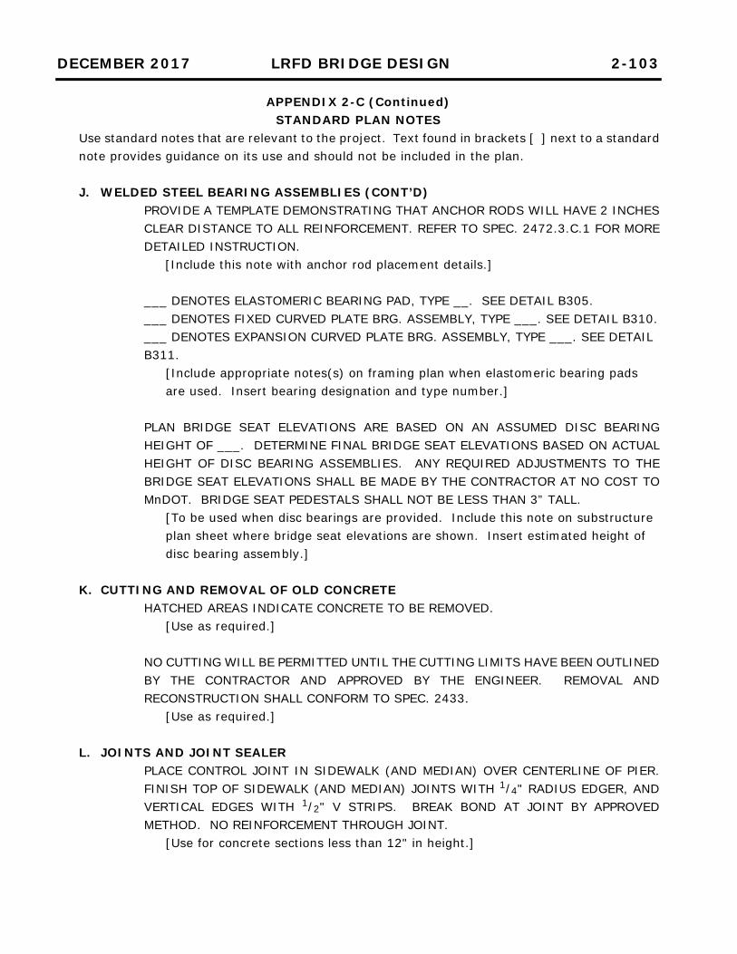
DECEMBER 2017 LRFD BRIDGE DESIGN 2-103
APPENDIX 2-C (Continued) STANDARD PLAN NOTES
Use standard notes that are relevant to the project. Text found in brackets [ ] next to a standard note provides guidance on its use and should not be included in the plan.
J. WELDED STEEL BEARING ASSEMBLIES (CONT’D)
PROVIDE A TEMPLATE DEMONSTRATING THAT ANCHOR RODS WILL HAVE 2 INCHES CLEAR DISTANCE TO ALL REINFORCEMENT. REFER TO SPEC. 2472.3.C.1 FOR MORE DETAILED INSTRUCTION. [Include this note with anchor rod placement details.]
___ DENOTES ELASTOMERIC BEARING PAD, TYPE __. SEE DETAIL B305. ___ DENOTES FIXED CURVED PLATE BRG. ASSEMBLY, TYPE ___. SEE DETAIL B310. ___ DENOTES EXPANSION CURVED PLATE BRG. ASSEMBLY, TYPE ___. SEE DETAIL B311.
[Include appropriate notes(s) on framing plan when elastomeric bearing pads are used. Insert bearing designation and type number.]
PLAN BRIDGE SEAT ELEVATIONS ARE BASED ON AN ASSUMED DISC BEARING HEIGHT OF ___. DETERMINE FINAL BRIDGE SEAT ELEVATIONS BASED ON ACTUAL HEIGHT OF DISC BEARING ASSEMBLIES. ANY REQUIRED ADJUSTMENTS TO THE BRIDGE SEAT ELEVATIONS SHALL BE MADE BY THE CONTRACTOR AT NO COST TO MnDOT. BRIDGE SEAT PEDESTALS SHALL NOT BE LESS THAN 3” TALL.
[To be used when disc bearings are provided. Include this note on substructure plan sheet where bridge seat elevations are shown. Insert estimated height of disc bearing assembly.]
K. CUTTING AND REMOVAL OF OLD CONCRETE HATCHED AREAS INDICATE CONCRETE TO BE REMOVED.
[Use as required.] NO CUTTING WILL BE PERMITTED UNTIL THE CUTTING LIMITS HAVE BEEN OUTLINED BY THE CONTRACTOR AND APPROVED BY THE ENGINEER. REMOVAL AND RECONSTRUCTION SHALL CONFORM TO SPEC. 2433.
[Use as required.]
L. JOINTS AND JOINT SEALER PLACE CONTROL JOINT IN SIDEWALK (AND MEDIAN) OVER CENTERLINE OF PIER. FINISH TOP OF SIDEWALK (AND MEDIAN) JOINTS WITH 1/4" RADIUS EDGER, AND VERTICAL EDGES WITH 1/2" V STRIPS. BREAK BOND AT JOINT BY APPROVED METHOD. NO REINFORCEMENT THROUGH JOINT.
[Use for concrete sections less than 12" in height.]

DECEMBER 2017 LRFD BRIDGE DESIGN 2-104
APPENDIX 2-C (Continued) STANDARD PLAN NOTES
Use standard notes that are relevant to the project. Text found in brackets [ ] next to a standard note provides guidance on its use and should not be included in the plan. L. JOINTS AND JOINT SEALER (CONT’D)
1½” TYPE B POLYSTYRENE BETWEEN APPROACH PANEL AND WINGWALL TO BE INCLUDED IN GRADING PLAN.
[Use as required.]
SUPERSTRUCTURE DIMENSIONS ARE BASED ON THE EXPANSION JOINT DIMENSION AT 90 F.
[Use when superstructure details show more than one expansion joint dimension for different temperatures.]
M. TIMBER BRIDGES
CONSTRUCTION REQUIREMENTS PER SPEC. 2403. [Use as required.]
ALL TIMBER PILING TO MEET REQUIREMENTS OF SPEC. 3471. ALL HARDWARE TO BE GALVANIZED PER SPEC. 3392. THREADS ON ALL BOLTS TO BE UPSET AFTER INSTALLATION.
[Use as required.] ALL WOOD TO BE FINISHED AS SHOWN IN THE BILL OF MATERIALS.
[Use as required.] TOP OF WING PILE WHICH PROJECTS OUTSIDE OF WING CAP SHALL BE SHAPED TO A 45° SLOPE.
[Use as required.] TREAT TOPS OF WING PILES PER SPEC. 2403.3.E. SEE SPEC. 3491 FOR PRESERVATION REQUIREMENTS.
[Use as required.] FILL IN BACK OF ABUTMENT IS NOT TO BE PLACED UNTIL AFTER SUPERSTRUCTURE HAS BEEN COMPLETED.
[Use as required.] FASTEN BACKING TO ABUTMENT PILES WITH TWO 60D NAILS AT EACH INTERSECTION.
[Use as required.]

DECEMBER 2017 LRFD BRIDGE DESIGN 2-105
APPENDIX 2-C (Continued) STANDARD PLAN NOTES
Use standard notes that are relevant to the project. Text found in brackets [ ] next to a standard note provides guidance on its use and should not be included in the plan.
M. TIMBER BRIDGES (CONT’D)
BOLT PROJECTIONS EXCEEDING 1" SHALL BE CUT OFF. REPAIR END OF BOLT BY PAINTING WITH AN APPROVED ZINC-RICH PRIMER.
[Use as required.]
TIMBER WINGWALL PILES ARE TO BE INSTALLED TO THE LENGTH SHOWN IN THE PLANS.
[Use as required.]
ALL WOOD SHALL BE PRESERVATIVE TREATED IN ACCORDANCE WITH SPEC. 3491. [Use as required.]
ALL WOOD THAT IS CUT OR DRILLED IN THE FIELD SHALL BE FIELD TREATED IN ACCORDANCE WITH SPEC. 2403.3.E.
[Use as required.]
ALL PLANKS FOR PREFAB PANELS SHALL BE DOUGLAS FIR-LARCH GRADE ___ (Fbo = ___ KSI).
[Use as required. Insert grade and reference design value.] FOR GLULAM RAIL ELEMENTS SEE PLAN SHEET ___ .
[Use as required. Insert sheet number.] RAIL POSTS, CURBS, SCUPPERS, AND RAIL SPACER BLOCKS SHALL BE DOUGLAS FIR-LARCH GRADE ___ (MIN. Fbo = ___ KSI).
[Use as required. Insert grade and reference design value.] ABUTMENT AND PIER CAPS SHALL BE DOUGLAS FIR-LARCH GRADE ___ POSTS AND TIMBERS (Fbo = ___ KSI). ALL OTHER LUMBER SHALL HAVE MIN. Fbo = ___ KSI.
[Use as required. Insert grade and reference design values.]
PILE PLATE ASSEMBLY SHALL BE SHOP PAINTED AFTER FABRICATION IS COMPLETED. PAINT PIER PILES, PLATES AND RINGS PER SPEC. 2452.3.J.1 AREAS OF PILES, PLATES AND RINGS BURNED DURING WELDING SHALL BE CLEANED AND SPOT COATED WITH ZINC-RICH PRIMER BEFORE FIELD PAINTING IS STARTED.
[Use as required.]

DECEMBER 2017 LRFD BRIDGE DESIGN 2-106
APPENDIX 2-C (Continued) STANDARD PLAN NOTES
Use standard notes that are relevant to the project. Text found in brackets [ ] next to a standard note provides guidance on its use and should not be included in the plan. M. TIMBER BRIDGES (CONT’D)
ALL STRUCTURAL STEEL SHALL CONFORM TO SPEC 3306 UNLESS OTHERWISE NOTED.
[Use as required.]
ALL STRUCTURAL STEEL SHALL BE GALVANIZED PER SPEC. 3394. [Use as required.]
N. MISCELLANEOUS
F.F. DENOTES FRONT FACE. B.F. DENOTES BACK FACE. E.F. DENOTES EACH FACE.
[Use as required.] THE CONTRACTOR SHALL MAKE FIELD MEASUREMENTS AS NECESSARY PRIOR TO FABRICATION OF THE __________ TO ASSURE PROPER FIT IN THE FINAL WORK.
[Use when not otherwise referenced to Spec. 2433. Insert component to be fabricated.]
BEAM LENGTH DIMENSIONS ARE SLOPED LENGTHS.
[Use where necessary for proper fit for prestressed beams.]
USE GREASE FROM THE "APPROVED/QUALIFIED PRODUCT LIST FOR BRIDGE PRODUCTS, BRIDGE GREASE"
[Use for dowel bar assemblies.] ALL MATERIAL TO BE EPOXY COATED. MATERIAL AND PLACEMENT TO BE INCLUDED IN PRICE BID FOR “DOWEL BAR ASSEMBLY (EPOXY COATED)”.
[Use for dowel bar assemblies.] ____ PASSAGE BENCH AT EL. _____. SURFACE WITH CLASS V AGGREGATE TO PROVIDE SMOOTH SURFACE. INCLUDED IN ITEM “RANDOM RIPRAP CLASS ___”.
[Use when a passage bench is required. Insert appropriate values.]
“X” DENOTES X END OF BEAM. [Include on framing plan for pretensioned concrete beam bridges.]

DECEMBER 2017 LRFD BRIDGE DESIGN 2-107
APPENDIX 2-C (Continued) STANDARD PLAN NOTES
Use standard notes that are relevant to the project. Text found in brackets [ ] next to a standard note provides guidance on its use and should not be included in the plan. N. MISCELLANEOUS (CONT’D)
PROVIDE 1/8 IN. 60 DUROMETER PLAIN ELASTOMERIC PAD OR PREFORMED FABRIC PAD MEETING AASHTO LRFD BRIDGE CONSTRUCTION SPECIFICATION ARTICLE 18.10. WAIVE THE SAMPLING AND TESTING REQUIREMENTS UNDER SPEC 3741, “ELASTOMERIC BEARING PADS,” AND AASHTO M251.
[Use as required.]

DECEMBER 2017 LRFD BRIDGE DESIGN 2-108
APPENDIX 2-D STANDARD SUMMARY OF QUANTITIES NOTES
Use standard notes that are relevant to the project. Text found in brackets [ ] next to a standard note provides guidance on its use and should not be included in the plan.
PAYMENT SHALL BE CONSIDERED INCIDENTAL TO ITEM “_______________”.
[For incidental quantities not listed as pay items (joint filler, nameplate, etc.). Fill in blank with appropriate pay item (e.g. for joint filler: Payment shall be considered incidental to item “Structural Concrete (3B52))”.]
INCLUDED IN WEIGHT OF “STRUCTURAL STEEL (33__ )”.
[Miscellaneous steel quantities (protection angle, etc.).]
DOES NOT INCLUDE TEST PILES. [Use when piling quantities are listed.]
INCLUDES SLAB, END DIAPHRAGM, MEDIAN BARRIER, SIDEWALK, AND RAILING REINFORCEMENT.
[Add to epoxy coated reinforcement bar totals. Remove components that do not apply.]
“CONCRETE WEARING COURSE (3U17A)” INCLUDES ______ SQUARE FEET FOR BRIDGE APPROACH PANELS.
[Use when the item as listed in the Summary of Quantities for Superstructure is paid for on a square foot basis. Insert area.]
PAYMENT FOR BEARINGS INCLUDED IN ITEM “BEARING ASSEMBLY” PER EACH.
[Use as required.]
PAYMENT FOR ANCHORAGES INCLUDED IN ITEM “ANCHORAGES TYPE REINF BARS” PER EACH.
[Use as required.]
PAYMENT FOR ANCHORAGES INCLUDED IN ITEM “GROUTED REINFORCEMENT BARS” PER EACH.
[Use as required.]
PAYMENT FOR THREADED COUPLERS INCLUDED IN ITEM “COUPLERS (REINFORCEMENT BARS) T-___” PER EACH.
[Use as required. Specify bar size.] MEMBRANE WATERPROOFING SYSTEM PER SPEC 2481.3.B TO BE INCLUDED IN ITEM “STRUCTURAL CONCRETE (____)”.
[Use as required. Insert concrete mix.]

DECEMBER 2017 LRFD BRIDGE DESIGN 2-109
APPENDIX 2-D (Continued) STANDARD SUMMARY OF QUANTITIES NOTES
Use standard notes that are relevant to the project. Text found in brackets [ ] next to a standard note provides guidance on its use and should not be included in the plan.
SEE DRAINAGE SYSTEM TYPE (B910).
[Use as required.]
PILE REDRIVING AND PILE ANALYSIS FOR THE REACTION PILES AND STATIC LOAD TEST PILE SHALL BE INCLUDED IN PRICE BID FOR “PILE LOAD TEST TYPE __”.
[Use as required. Insert type number.]
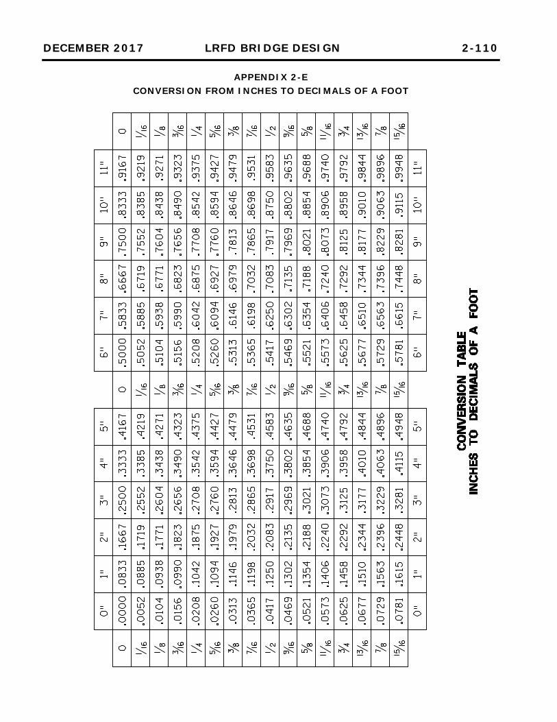
DECEMBER 2017 LRFD BRIDGE DESIGN 2-110
APPENDIX 2-E CONVERSION FROM INCHES TO DECIMALS OF A FOOT