april 2009 lrfd bridge design 15-1mndot.org/bridge/pdf/lrfdmanual/section15.pdf · april 2009 lrfd...
TRANSCRIPT
APRIL 2009 LRFD BRIDGE DESIGN 15-1
Bridge load ratings are administered and performed by the Bridge Rating Unit of the Mn/DOT Bridge Office. Bridge load ratings may also be performed by other qualified engineers. Bridge ratings are calculated in accordance with the AASHTO Manual for Condition Evaluation of Bridges (MCE). This manual refers the user to the AASHTO Standard Specifications for Highway Bridges (Std Specs) for much additional needed information. A new rating method, Load and Resistance Factor Rating (LRFR), has been introduced. This method is described by AASHTO in The Manual for Bridge Evaluation, First Edition, 2008. Minnesota Statute Chapter 169 prescribes weights of vehicles. Other references related to bridges, ratings, inspections, vehicles, trucks, and weights include Minnesota Statutes, Chapters 163, 165, and 168, and Minnesota Rules, Chapters 8810 and 8820. All bridges in Minnesota open to the public, carrying cars and trucks, with spans of 10 feet and more are rated. This includes all county, local, and private bridges. Railroad bridges are rated by the operating railroad. Bridges that carry pedestrians or recreational traffic are rated only in special cases. Culverts, with spans of 10 feet or more, are also rated, but by a different method. See the Article 15.10 of this Manual for more information. Mn/DOT rates the bridges on the state highway system (Interstate, US, and Minnesota). Counties, cities, etc. each rate their own bridges. Where there are privately owned bridges on public roads, the owners are responsible for the ratings. Mn/DOT does not rate bridges that are owned by railroads. The RR is to perform necessary load ratings for their bridges since they control railroad loads. In our Pontis database bridge inventory we record only the design RR load. Temporary bridges are rated, similarly to permanent bridges. Also, overweight truck permits for temporary bridges are evaluated in the same manner as for permanent bridges. Bridges are rated by the Load Factor Rating (LFR) method whenever possible. The Allowable Stress Rating (ASR) method is accepted for
15. BRIDGE LOAD RATING
15.1 General
APRIL 2009 LRFD BRIDGE DESIGN 15-2
timber bridges or when there are no LFR provisions available for use. The Load and Resistance Factor Rating (LRFR) method is acceptable for new bridges that are designed by LRFD and are not compatible with Virtis. Bridges are rated at two different stress levels, Inventory level and Operating level. The Operating level is used for load posting and for evaluation of overweight permits. In almost all cases only the primary load carrying members of the superstructure are rated. Decks or substructures may have to be investigated in unusual circumstances such as severe deterioration. Unusually heavy permit loads may also require investigation of the deck and substructures. Generally ratings are calculated for shear and for bending moment, and at the tenth points of each span. Other points are rated as needed, for example at changes of section. Other force effects that are checked, as needed, are axial load and curvature forces. When rating a bridge, the final overall bridge rating will be the rating of the weakest point of the weakest member within the whole bridge. This rating is recorded on the cover sheet of the rating form. This member is called the controlling member (controlling rated member) of the bridge. The weakest link may change with different rating vehicles. This is because rating vehicles of different weights, axle spacings, and/or lengths have different effects on different members and spans. The identification of the controlling member, location, and limit state for each rated vehicle is recorded on page two (or a subsequent page) of the rating forms. Design load ratings (inventory and operating) are calculated and reported in terms of the HS 20 design load. For example, if the calculated rating factor is 1.15, the rating is recorded as HS 23.0. For bridges rated by LRFR, report the design load ratings by their rating factors. For example, “RF = 1.11” and “RF = 1.99,” respectively for inventory and operating. Sources of information for a new rating or a rerating include the original plan, as-built plan, the repair plan(s), existing rating, bridge inventory data, shop drawings, and inspection reports.
APRIL 2009 LRFD BRIDGE DESIGN 15-3
Use the material strengths as given on the plan. If there is no plan and no other source is available, select from the values given in the MCE based on the year of construction. In the past, most continuous steel beam spans have been designed as non-composite in the negative moment region. Rate them the same way. Conversely, if the beam was designed for composite action in the negative moment region, rate it as composite and with the longitudinal slab rebars included in the section properties. Bridge load raters have the option of using the plastic capacity of steel per Article 10.50 of the Std Specs. Use the overload requirements of Article 10.57 of the AASHTO Std Specs when performing steel beam ratings. The use of computer programs is preferred for rating. Virtis is an AASHTOWare rating program introduced in 2001. It is capable of rating most bridge types. Other programs may be used for rating, provided they follow the MCE and all applicable AASHTO specifications. Bridges entered in Virtis shall use the "Girder System Definition" whenever the bridge geometry will fit within the limitations of Virtis. When using the "Girder Line Superstructure Definition", rate an interior beam under a vehicle traffic lane. If a rating is being done with Virtis, there are additional rating instructions available specific to Virtis. Inquire to the Bridge Rating Engineer. A refined analysis is a bridge rating done by more rigorous methods than usual. Some of these methods include: finite element analysis, yield line theory, strut and tie analysis, three dimensional modeling and analysis, and load testing. Although not common practice, bridge load raters have the option to do a refined analysis to improve the rating if the project meets certain criteria. The criteria include: the avoidance of posting a
15.2.1 Computer Programs
15.2 Analysis
15.2.2 Refined Analysis
APRIL 2009 LRFD BRIDGE DESIGN 15-4
bridge, improving the rating for overweight permit trucks, improving the capacity to qualify for rehabilitation work, and at the District’s request. Some bridge types will by default receive a refined analysis. Examples are curved steel girders, segmental concrete boxes and cable stayed bridges. These bridges are designed with specialized software developed specifically for these complex structures. The use of refined analysis is limited. The increased time, effort, and cost of the analysis must be balanced against the workload of the staff and the potential benefits. Dead loads and their distribution are calculated according to AASHTO. Railings, sidewalks, utilities and medians may be divided uniformly among all beams if they are located symmetrically on the deck cross section. Otherwise a different distribution method should be used which is logically sound. Low slump concrete wearing courses and latex modified wearing courses are considered to be fully composite with the base slab. The topmost 0.5 inch of the wearing course or slab is not considered to be effective for composite action or section properties. When the deck is poured in two steps, the composite section usually consists of a 7 inch thick initial pour followed by a 2 inch low slump wearing course. DL1 Is defined as noncomposite dead load (stage 1) and DL2 as composite dead load (stage 2). DL1 includes the weight of the beam, diaphragms, and the initial slab pour. The remainder of the dead load is part of DL2. Mn/DOT considers the effective composite deck supporting DL2 to be the initial slab pour thickness. The effective composite deck supporting the live load (stage 3) is the full deck thickness including the wearing course minus 0.5 inch. Most computer programs including BARS and Virtis will not accept these two different thicknesses of composite deck for stages 2 and 3. It is then necessary to use the effective composite deck for live load as the one that also supports DL2. Unless otherwise confirmed by inspection, include a dead load for utilities of 2 psf of deck area in rural areas and 3 psf in cities and urban areas. Higher loads may be required if heavier utilities are shown on the plan or are known to exist.
15.3 Loads
APRIL 2009 LRFD BRIDGE DESIGN 15-5
Use a stool height of 1.5 inches for bridges designed in or after 1990 and 1 inch for bridges designed before. Add as uniform dead load an additional weight to account for additional stool, residual camber, slope of the deck, superelevation, etc. If the design includes an allowance for future dead loads, such as a wearing course, these should not be included in the ratings until such time as they are actually placed. For steel bridges, account for the extra dead loads such as welds, splices, bolts, connection plates, etc. For beam bridges, this generally ranges from 2 % to 5 % of the main member weight. Use the Std Spec for lateral distribution of live loads. Standard gage width (also called tread width) is 6 feet. For overweight permits treat gages of up to 7.0 feet as though they are 6 feet. For gage widths wider than this, an adjustment may be made to the axle weight so that an analysis can be completed as if it is a conventional truck. Virtis version 5.5.0 introduced the analysis of non-standard gages. Axle configurations with more than four tires may need to be analyzed manually to determine their distribution factors. The AASHTO Guide Specification for Distribution of Loads for Highway Bridges (1994) (LRFD live load distribution) may by used for ratings otherwise done by LFR methods. When rating for overweight permits on members that support more than one traffic lane (trusses, two-girder systems, floor beams, etc.), apply the permit truck to the lane that has the greatest effect on that member. Apply the design load (HS 20) to the adjacent lanes. In the rating equation the adjacent lane load may be applied as a negative term in the numerator. These loads shall be limited to the traffic lanes. When rating for posting, apply the loads to the lanes in the same manner as is used for design. When rating a bridge with a sidewalk, use the AASHTO pedestrian loads. In the rating equation, apply the sidewalk dead and live loads as negative numbers in the numerator.
APRIL 2009 LRFD BRIDGE DESIGN 15-6
Use a phi factor of 0.91 for prestressed concrete flexure in load factor rating. For bridges with an NBI superstructure condition of fair (SCC = 5), apply a capacity reduction factor of 0.95 to the bridge or to the member whose condition led to this code. If the condition is poor (SCC = 4), or lower apply a capacity reduction factor of 0.85. These factors may be modified if inspection reports clearly show different factors are appropriate for rating, i.e., if the condition is clearly documented with measured section losses that can be incorporated into the rating calculations. These reduction factors should not be used if the reason for the reduced condition rating is not in the direct load path of the bridge support system. New bridges should be rated prior to the bridge being opened to traffic. The operating rating for the bridge should be computed and listed with other design data on the plan. Additional overweight permit vehicle ratings are also computed for all TH bridges and on other routes where overweight loads are permitted by local agencies. For Mn/DOT bridges, the records remain inactive until Bridge Management is informed that the bridge has been opened to traffic. If any changes are made to the bridge during construction that would affect the rating, report these changes to the Bridge Ratings Unit (or the person who did the original rating). Also record these changes on the as-built plans. This includes strand pattern changes for prestressed beams. The bridge rating is then recalculated. A new bridge rating should be calculated whenever a change occurs that would significantly affect the rating. The most commonly encountered types of changes are:
• A modification that changes the dead load on the bridge. (For example: a deck overlay.)
• Damage that alters the structural capacity of the bridge. (For
example: being hit by an errant or oversize load.)
15.4 Rating Equation Factors
15.5 Rating New Bridges
15.6 Re-rating Existing Bridges
APRIL 2009 LRFD BRIDGE DESIGN 15-7
• Deterioration that alters the structural capacity of the bridge. (For example: rust, corrosion or rot. Scheduled inspections are usually the source of this information).
• Settlement, movement, or scour of a pier or abutment.
• Repairs or remodeling. • A change in the AASHTO rating specification.
• An upgrading of the rating software.
• A change in laws regulating truck weights.
The new rating should be completed, signed, dated, and filed, as outlined in Articles 15.16 and 15.17 of this manual. When requested, a new TH rating may be calculated for a proposed repair or rehabilitation project. This type of rating is kept on temporary hold until the Bridge Rating Unit is informed that the project has been completed. The request for a rerating is passed from the Program Administrator to a Bridge Rating Engineer. The Bridge Rating Engineer will do preliminary evaluation upon receipt of the information. The time frame of when the rerating is to be completed will depend on the level of importance determined from this evaluation. The rerating shall be completed immediately if the request is due to damage or severe deterioration and for other issues no more than 45 days later. Substructures are not normally rated. Rating may be required, at the judgment of the engineer, in these circumstances:
• If an unusually heavy truck applies for a permit. • If inspections reveal there is substantial damage or deterioration
to a substructure. • If for any other reason, the capacity for the usual legal and permit
traffic is questioned.
15.7 Substructures
APRIL 2009 LRFD BRIDGE DESIGN 15-8
Some types of bridges can not be rated by the rating software we now use or by any rating software available on the market. For these bridges the designers should compute the ratings using the design software. The bridge types to which this applies include: post-tensioned concrete (simple span and continuous, segmental and non-segmental), curved steel (simple span and continuous), arches, rigid frames, continuous trusses, “single point”, suspension, and cable stayed bridges. For trunk highways, in addition to rating, provisions are needed to evaluate trucks that apply for overload permits. If the design software will accept custom truck configurations, rate for the Mn/DOT Standard Permit Trucks. Record the lowest or controlling rating factor for each truck. If custom trucks cannot be run, one solution is to provide the capacity along with the influence line, for the critical points. Rating information is needed for the critical locations of negative and positive moment. If shear is or could be critical at any point in a member, data should be provided for that also. The information needed for each location is the moment (or shear/axial force) capacity, dead load effects, secondary prestress effects (if applicable), the capacity remaining for live load and the live load influence line. These should all be equated to the width of one beam spacing. State the load factors, capacity reduction factors, and live load distribution factors that were applied. The complete submittal is to include plan sheets necessary to convey the essential information used in the rating. This includes the general plan and elevation, the deck cross section, the framing plan, and the beam elevation. Any questions about this procedure should be directed to the Bridge Rating Engineer. Timber plank decks shall be rated. Use all the provisions of Std Specs, Fig. 3.7.7 A with applicable footnotes. In other words, rate decks with individual axles of 17 k or whatever the posting truck has. Use wet condition for all rated timber members. The repetitive use factor, Cr , can be used for plank decks, if they are covered by bituminous or perpendicular planks for load distribution.
15.9 Timber Bridges
15.8 Non-Standard Bridge Types
OCTOBER 2011 LRFD BRIDGE DESIGN 15-9.1
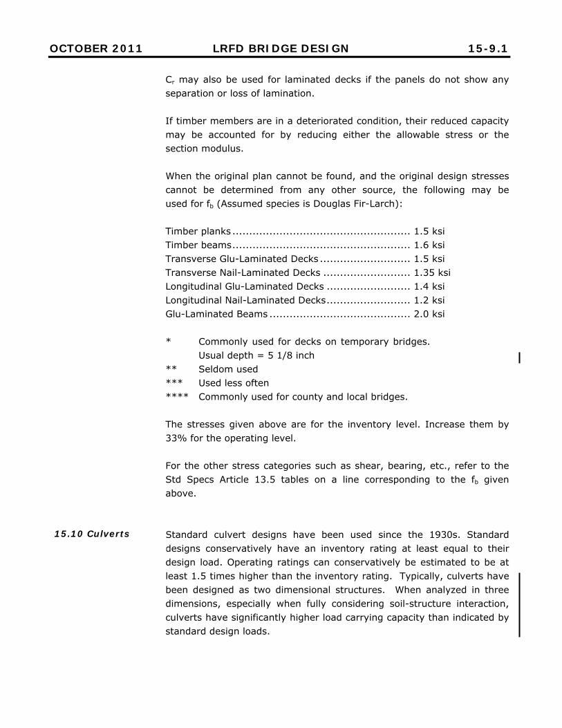
Cr may also be used for laminated decks if the panels do not show any separation or loss of lamination. If timber members are in a deteriorated condition, their reduced capacity may be accounted for by reducing either the allowable stress or the section modulus. When the original plan cannot be found, and the original design stresses cannot be determined from any other source, the following may be used for fb (Assumed species is Douglas Fir-Larch): Timber planks ..................................................... 1.5 ksi Timber beams ..................................................... 1.6 ksi Transverse Glu-Laminated Decks ........................... 1.5 ksi Transverse Nail-Laminated Decks .......................... 1.35 ksi Longitudinal Glu-Laminated Decks ......................... 1.4 ksi Longitudinal Nail-Laminated Decks ......................... 1.2 ksi Glu-Laminated Beams .......................................... 2.0 ksi * Commonly used for decks on temporary bridges.
Usual depth = 5 1/8 inch ** Seldom used *** Used less often **** Commonly used for county and local bridges. The stresses given above are for the inventory level. Increase them by 33% for the operating level. For the other stress categories such as shear, bearing, etc., refer to the Std Specs Article 13.5 tables on a line corresponding to the fb given above. Standard culvert designs have been used since the 1930s. Standard designs conservatively have an inventory rating at least equal to their design load. Operating ratings can conservatively be estimated to be at least 1.5 times higher than the inventory rating. Typically, culverts have been designed as two dimensional structures. When analyzed in three dimensions, especially when fully considering soil-structure interaction, culverts have significantly higher load carrying capacity than indicated by standard design loads.
15.10 Culverts
OCTOBER 2011 LRFD BRIDGE DESIGN 15-9.2
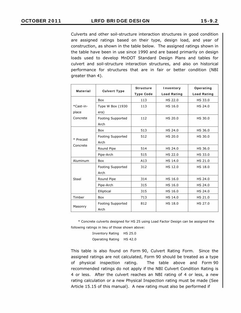
Culverts and other soil-structure interaction structures in good condition are assigned ratings based on their type, design load, and year of construction, as shown in the table below. The assigned ratings shown in the table have been in use since 1990 and are based primarily on design loads used to develop MnDOT Standard Design Plans and tables for culvert and soil-structure interaction structures, and also on historical performance for structures that are in fair or better condition (NBI greater than 4).
Material Culvert Type Structure
Type Code
Inventory
Load Rating
Operating
Load Rating
*Cast-in-
place
Concrete
Box 113 HS 22.0 HS 33.0
Type W Box (1930
era)
113 HS 16.0 HS 24.0
Footing Supported
Arch
112 HS 20.0 HS 30.0
* Precast
Concrete
Box 513 HS 24.0 HS 36.0
Footing Supported
Arch
512 HS 20.0 HS 30.0
Round Pipe 514 HS 24.0 HS 36.0
Pipe-Arch 515 HS 22.0 HS 33.0
Aluminum Box A13 HS 14.0 HS 21.0
Steel
Footing Supported
Arch
312 HS 12.0 HS 18.0
Round Pipe 314 HS 16.0 HS 24.0
Pipe-Arch 315 HS 16.0 HS 24.0
Elliptical 315 HS 16.0 HS 24.0
Timber Box 713 HS 14.0 HS 21.0
Masonry Footing Supported
Arch
812 HS 18.0 HS 27.0
* Concrete culverts designed for HS 25 using Load Factor Design can be assigned the
following ratings in lieu of those shown above:
Inventory Rating HS 25.0
Operating Rating HS 42.0
This table is also found on Form 90, Culvert Rating Form. Since the assigned ratings are not calculated, Form 90 should be treated as a type of physical inspection rating. The table above and Form 90 recommended ratings do not apply if the NBI Culvert Condition Rating is 4 or less. After the culvert reaches an NBI rating of 4 or less, a new rating calculation or a new Physical Inspection rating must be made (See Article 15.15 of this manual). A new rating must also be performed if

OCTOBER 2011 LRFD BRIDGE DESIGN 15-9.3
[ This page intentionally left blank ]
OCTOBER 2011 LRFD BRIDGE DESIGN 15-10
cracking or distortion occurs beneath traffic lanes. Cracking or physical distortion under traffic lanes indicates current permit or legal truck weights should be restricted or limited. Form 90 may be used for rating all culverts in the State of Minnesota, including county, city, township, etc. Form 90 is to be filled out by the Bridge Office for state owned culverts and by local personnel for locally owned culverts. The procedure for the completion of a rating with Form 90 is as follows:
• Review the latest inspection report • Confirm that the culvert condition code is 5 or greater • Fill in the general information at the top. • Fill in the inventory and operating ratings, HS xx and HS zz. The
Rating Guidelines table may be used for these numbers. • If the table guidelines are not followed, an explanation should
be added. • Fill in the blanks at the bottom with the names and dates of the
last inspection and the rating. See the FHWA Culvert Inspection Manual, Chapter 5. Culverts may be posted for reduced loads. Form PIR is also used to document these posted load limits. Box culverts with a clear span over 20 feet are to be rated as bridges, not with Form 90. Precast concrete arches on footings (type 512) with spans up to 43 feet, may be rated as culverts using Form 90. In most cases the bridge type will indicate if the structure is a culvert or a bridge. This may not be true for the Pontis bridge types: concrete arch, steel arch, and prestress arch. For these types, the barrel length or span length can be checked.
OCTOBER 2011 LRFD BRIDGE DESIGN 15-11
Box culverts of the design “Type W” were built mostly in the era of 1929 to 1944. They had a single layer of reinforcement and were designed as simple span elements on all sides. For this reason, they are rated lower. Pre-1929 box culverts may be included with this category. Truss bridge gusset plates are to be rated. There are separate MnDOT documents which can be used as guidelines. They include: MnDOT Truss Bridge Gusset Plate Design Review Procedure, MnDOT Interpretation of Truss Bridge Gusset Plate Review Results, Excel spreadsheets, and a sample calculation. The spreadsheet and sample calculation can be obtained by request from the Bridge Rating Engineer. The other documents are found in the Memo to Designers (2008-02): Truss Bridge Gusset Plate Analysis located in the Memos section of this manual. Load testing is the rating method where a controlled test is conducted on a bridge. The bridge is monitored with strain gages and other instruments. Normal traffic is stopped and calibrated test trucks are directed across the bridge. Extensive calculations are required before and after the test. A computer model is “calibrated” to the load test results. Load testing is used when the bridge cannot be rated by ordinary methods or when the ordinary methods give unrealistic results. See MCE 5.0. Proof load testing is not recommended due to safety considerations. The Minnesota Posting Trucks are:
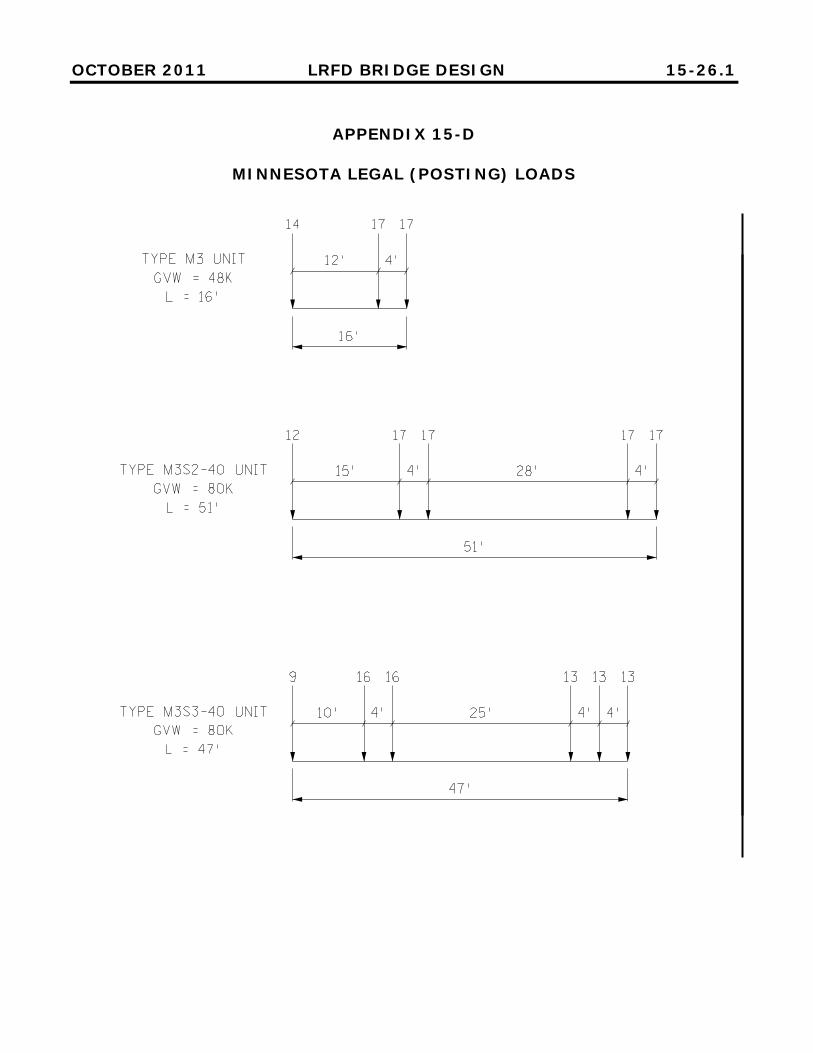
“Minnesota Legal (Posting) Loads” used for bridges on both 9 ton and 10 ton routes. These can be found in Appendix 15-D. Bridge Posting Loads for Single-Unit SHVs that Meet Federal Bridge Formula B. See Figure 7.4.3.2 in MCE revisions: Trucks SU4, SU5, SU6, and SU7.
15.11 Gusset Plates
15.12 Load Testing
15.13 Load Posting
15.13.1 General

OCTOBER 2011 LRFD BRIDGE DESIGN 15-12
The Posting Signs are:
Sign R12–1a, which is usually used for lower posting weights and shorter bridges. Sign R12–5, which is used for most postings at or below 40 tons. The posting trucks associated with the three silhouettes are, top to bottom: M3, M3S2, and M3S3. Trucks SU4 thru SU7 are associated with the top silhouette, the single truck. Sign R12–5a, which may be used when only the single unit truck requires posting. Sign R12–X11, which is used where higher posting limits are required due to seasonal or permit loads. (45 tons only)
These signs can be found at: http://www.dot.state.mn.us/trafficeng/publ/signsummary/signsummary.pdf Supplemental signs, advance warning signs, other related bridge signs, and instructions on their use can be found in the above manual and in the Minnesota Manual of Uniform Traffic Control Devices. All calculations for posting should be done in accordance with the MCE, at the operating level. Any bridge with an operating rating of less than HS 27 should be checked to see if posting is required. If any rating factor for any vehicle is below the maximum level as shown in Article 15.13.2, fill in Form PW completely. It will then become the third sheet of the rating documents. The posting weights that are to be placed on the posting sign are entered on the front page Form RC – CL or Form RC - TH. The sign type should also be indicated there. Round the calculated posting tonnages down to the nearest even ton. (Exception: 3 T or 5 T may be used on sign R12-1a.) With sign R12–5, post the two combination vehicles at the same tonnage, at the lesser of the two calculated tonnages.
OCTOBER 2011 LRFD BRIDGE DESIGN 15-13
With sign R12–5, all three vehicles must be posted. The maximums for this sign are: 40 T, 40 T, 40 T. Sign R12–5a may be used instead of sign R12–5 when posting is required for the single unit truck only. (RFs for M3S2-40 and M3S3 are > 1.24) The explanation for posting for rating factors above 1.00 is that Minnesota Statutes provide for many exceptions to the basic legal loads. There are increases of 10% in the winter, harvest increases, the “Timber Haulers Bill”, etc. On state highways the posting notification is sent by memo from the State Bridge Engineer to the District Engineer. The district office must inform the Bridge Management Unit when the posting signs are in place. When a rating is completed and indicates a bridge is to be posted, the posting signs must be erected within 30 days after notification of their requirement. If there are significant changes in the bridge condition or in the posted weight, temporary signs should be erected in the interim. When a rating is completed and indicates a bridge is to be posted, it is mandatory that the bridge be posted unless the bridge owner elects to provide expedited repairs to strengthen the bridge to carry legal loads. Notify the permit office immediately of any new trunk highway bridge posting.

OCTOBER 2011 LRFD BRIDGE DESIGN 15-14
Truck M3 (24 T) For RF (Rating Factor) < 0.125, the bridge must be closed. For 0.125 ≤ RF ≤ 1.10, post at indicated tonnage. For 1.10 < RF, this model is not applicable. Defer to Truck SU4.
Truck SU4 (27 T)
For 0.89 ≤ RF ≤ 1.10, post at indicated tonnage and use sign R12-5 or R12–5a.
For 1.10 < RF, this model is not applicable. Defer to Truck SU5. Truck SU5 (31 T)
For 0.87 ≤ RF ≤ 1.10, post at indicated tonnage and use sign R12-5 or R12–5a.
For 1.10 < RF, this model is not applicable. Defer to Truck SU6. Truck SU6 (34.75 T)
For 0.89 ≤ RF ≤ 1.10, post at indicated tonnage and use sign R12-5 or R12–5a.
For 1.10 < RF, this model is not applicable. Defer to Truck SU7. Truck SU7 (38.75 T)
For 0.89 ≤ RF ≤ 1.025, post at indicated tonnage and use sign R12-5 or R12–5a.
For 1.025 < RF ≤ 1.13, post at 40 T. For 1.13 < RF, no posting required.
Truck M3S2 – 40 and Truck M3S3 (40 T) For RF < 0.35, post as indicated by truck M3 and use sign R12-1a. For 0.35 ≤ RF ≤ 1.00, post as indicated with sign R12-5. For 1.00 < RF ≤ 1.12, post at 40 T with sign R12-5. For 1.12 < RF ≤ 1.24, post with the sign R12-X11, unless one of the
single trucks, M3 thru SU7, requires posting, then use sign R12-5 and use 40 T for these two trucks.
For 1.24 < RF no posting required, unless one of the single trucks, M3 thru SU7, requires posting, then either sign R12–5 with 40T for the two combination vehicles or sign R12–5a may be used.
15.13.2 Rating Factors for Posting
APRIL 2009 LRFD BRIDGE DESIGN 15-15
This section applies to state trunk highways only. Maximum vehicle weights are defined in Minnesota Statutes. Under certain conditions, trucks may obtain permits to travel at greater weights. Overweight and overdimension permits are issued by the Office of Freight and Commercial Vehicle Operations (OFCVO). Among the tasks the OFCVO performs in the issuance of a permit are: communication with the trucking company, recording of information, checking legal requirements for the truck, issuing the permit, collecting fees, determining the route (except for certain annual permits), and forwarding pertinent information to the Bridge Office for bridge checks. The computer program they use for processing permits is called RoutebuilderNT. The OFVCO issues annual permits for trucks weighing up to a maximum of 145,000 pounds. A holder of an annual permit may make an unlimited number of trips during the year of the permit. For routing they utilize the permit codes as recorded on our rating forms and maps. The trucker may make his own judgment as to which weight class (A, B, or C) his truck fits, or he may ask the permit office to determine the weight class. The permit office forwards these to the Bridge Office if they are uncertain of the weight class. These are commonly called “general checks.” The OFVCO also issues single trip permits. There is no maximum weight for single trip permits other than bridge capacity. All permit trucks have weight limits for single axles, and for certain axle groups. Single trip permits are screened by the permit technicians at the permit office. Those permits with routes that cross bridges which are of questionable capacity are sent to the Bridge Rating Unit of the Bridge Office, for further evaluation. This is commonly called a “bridge check”. The permit office screening techniques utilize the permit codes as recorded on our rating forms. Minnesota Standard Permit Trucks G-80, are shown in Appendix 15-E. Rating factors and restriction codes are recorded on the rating forms for these trucks. The Bridge Management unit enters the codes into Pontis. They are also copied to permit bridge logs, and the annual permit routing maps. In this procedure, Class C is considered to be the composite of the three trucks: Std. C, P411, and P413 (sometimes called P4).
15.14 Overweight Permits
APRIL 2009 LRFD BRIDGE DESIGN 15-16
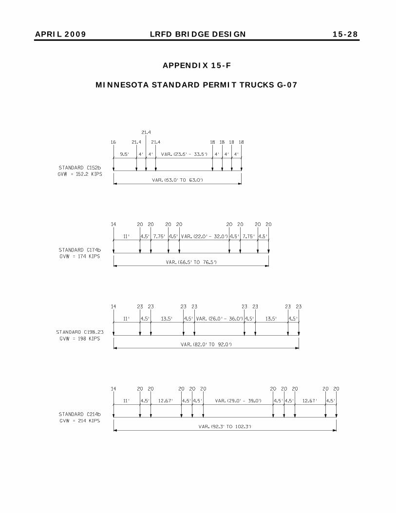
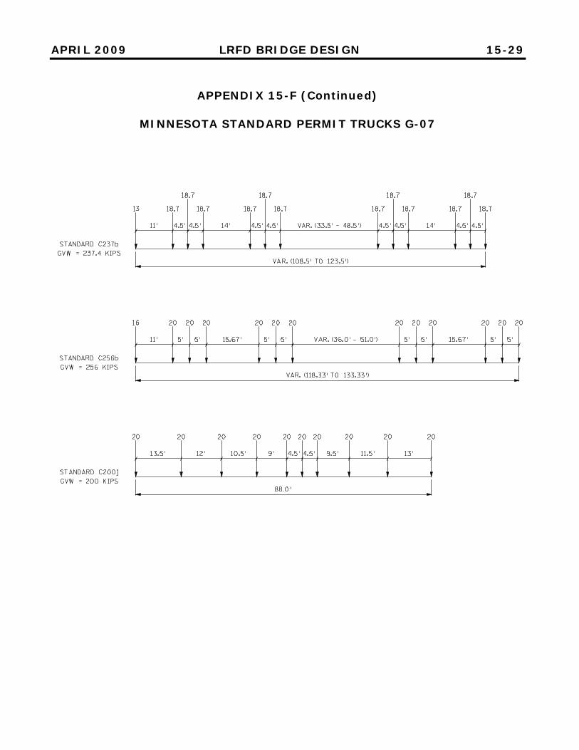
Minnesota Standard Permit Trucks G-07 are shown in Appendix 15-F. These are a new generation of permit trucks. See separate instructions for their use. If the initial RF for a permit truck is less than 1.0, the truck might still be allowed to cross the bridge under a restriction. Overweight Permit Restrictions are shown in Appendix 15-C. The standard gage of an axle is 6.0 feet, as given in the Std Specs, Figure 3.7.7A. Permits of 6 to 6.5 feet gage are evaluated as though they were 6.0 ft. Axles wider than this and axles with more than 4 tires may be evaluated at a reduced equivalent weight, then run in Virtis. (This reduced weight may be different for different type bridges depending on which live load distribution formula applies for the bridge.) Virtis has a non-standard gage feature. It is slow to use and works only with bridges that are entered as a system. A truck traveling under an overweight permit is by law prohibited from crossing a load posted bridge. This method of rating is to be used when the capacity cannot readily be calculated because of one or more of these reasons:
• No bridge plan is available • Concrete bridges with amount of the reinforcement unknown • A bridge that has a poor or deteriorated condition • Deteriorated piling or substructures • A bridge that has been carrying a known amount of traffic and not
suffering any apparent distress • A culvert that has a poor or deteriorated condition
Follow AASHTO MCE 7.4.1. A registered professional engineer thoroughly familiar with the bridge shall do this rating.
15.15 Physical Inspection Rating (PIR)

APRIL 2009 LRFD BRIDGE DESIGN 15-17
The rating is determined by the engineer upon careful consideration of all available information, including bridge condition (corrosion, spalling, damage, deflection, settlement, cracking, etc.), age, type of construction, redundancy, ADTT, loading (past, present, and future), etc. Engineering judgment or a combination of calculations, experience, and judgment is used. The numbers in the rating should follow the ratios (approximately) in the following table, where T is the posting tonnage:
Single Weight Posting,
Sign R 12 – 1A
Posting Sign R 12 - 5
Rating
Single Vehicle
Combination Vehicles
Inventory Operating
T T 1.6 x T HS (0.6 x T) HS (T)
A PIR rating is documented with Form PIR and accompanied by the cover form, RC - TH or RC – CL. For type of analysis check “Other” and write in “PIR” and for method of rating check “No Rating Computations Performed.” Owners should schedule inspections for bridges rated by PIR at intervals of 12 months or less. Bridges or culverts rated by this method shall be re-rated after each inspection if there is a change in the superstructure condition code stemming from a problem in the direct load path. Bridges rated with this method shall have all overweight permits prohibited, unless the bridge has a documented history of carrying known heavier trucks without any problems. As new ratings are needed, rating reports should be prepared on Mn/DOT forms according to the following guidelines: This report should include summaries of the controlling members, controlling locations, rating factors, capacity reduction factors, and limits states for all unique members and/or member types within the bridge. Include a sketch or layout of the bridge to identify where the referenced rating locations are. The report will be a minimum of two pages (a
15.16 Forms and Documentation

OCTOBER 2011 LRFD BRIDGE DESIGN 15-18
routine Virtis bridge, for example). Additional pages of documentation may be required, for complex bridges, when the rating software is not available to MnDOT, when refined analysis is used, gusset plate analysis, etc. Fully document the loading conditions used for the rating. This includes changes from the original plan, deck replacements or thickness modifications, railing modifications or replacements, bridge widening, unusual loading conditions, and damage or deterioration incorporated in the rating. List the condition or event, its key details, and the date of the event. In documenting the deck changes, list thicknesses of: 1) original, 2) amount milled, 3) overlay, and 4) final thickness. Enter the NBI Condition Rating values, which are sometimes called condition codes. For new bridges, these will all be 9. For re-rating old bridges, the current ratings are found on the MnDOT Structure Inventory Report. Also document rating considerations given for damage or deterioration. A bridge in a deteriorated condition will require more detail and explanation in the rating. Clearly document assumptions used in the rating calculations or structural modeling. If the information is readily found in the computer files (Virtis or other software) it need not be repeated. Form RC – TH (or RC – CL) is the cover sheet required for all bridges that have a calculated bridge rating. That is all bridges that have a span over 10 ft and are not culverts. It is to be accompanied by at least one additional sheet, usually Form RD - TH (or RD – CL). The cover page of the completed rating must be signed by a registered professional engineer. The rating is to be checked by a second engineer. The rating forms can be found on the Bridge Office Web Site at Documents, Downloads, Forms, and Links, in the section titled Bridge Rating and Load Posting Reports. The url is: http://www.dot.state.mn.us/bridge/docsdown.html The forms are also listed and summarized in Appendix 15-B of this manual. The most recent rating supersedes any and all preceding ratings.
OCTOBER 2011 LRFD BRIDGE DESIGN 15-19
The original copy of the rating should be retained in the files of the bridge owner. For TH bridges these are the files of the MnDOT Bridge Ratings Unit. Deliver copies of all ratings (township, county, city, state, etc.) to:
Bridge Management Unit MnDOT Bridge Office 3485 Hadley Avenue North Oakdale, MN 55128-3307
The copies are kept on file and selected information will be entered in SIMS. From there annual reports are prepared and sent to the FHWA. Copies of MnDOT bridge ratings will be scanned and entered in EDMS. From there, they can be accessed by bridge inspectors.
15.17 Submittal / Filing

APRIL 2009 LRFD BRIDGE DESIGN 15-20
APPENDIX 15-A
GLOSSARY
AASHTO --- American Association of State Highway and Transportation Officials ADTT --- Average Daily Truck Traffic. (In Pontis this is called HCADT) ASD --- Allowable Stress Design: The original AASHTO design method. The safety factors are applied to the material strength portion of the structure capacity. Also called working stress design (WSD). ASR --- Allowable Stress Rating: The rating version of ASD Dead Load --- Those loads that are constant in magnitude, fixed in location, and remain in place permanently or for a long period of time. EDMS --- Electronic Document Management System FHWA --- Federal Highway Administration GVW or Gross Vehicle Weight --- Total weight of the vehicle including the empty weight plus all variable loads such as freight, passengers, fuel, etc. (See also Minn Stat 169.01, Subd. 46.) Impact --- An additional live load expressed as a per cent increase of the vehicle live load. It represents the vertical forces due to vibrations and bouncing of a vehicle as it passes over a bumpy bridge deck. AASHTO specifies the methods of calculation. It is always applied with the vehicle live load unless a specific reason is given otherwise. Inventory Rating Level --- As defined by AASHTO, it is equivalent to the design level of stress. A bridge subjected to no more than this stress level can be expected to safely function for a life of 75 or more years. Kip or k --- A weight of 1000 pounds Legal Load --- The maximum GVW a truck may have without a permit. Minnesota Statute 169 defines this. Legal Trucks --- These are the model trucks used to determine load postings on bridges. The MCE defines them. Minnesota has adopted variations of them as given in Appendix 15-D. (Sometimes called Posting Trucks)
APRIL 2009 LRFD BRIDGE DESIGN 15-21
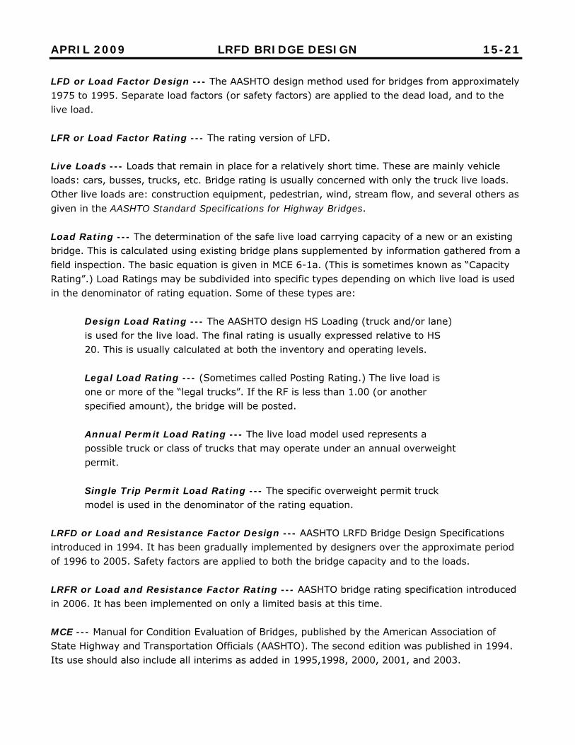
LFD or Load Factor Design --- The AASHTO design method used for bridges from approximately 1975 to 1995. Separate load factors (or safety factors) are applied to the dead load, and to the live load. LFR or Load Factor Rating --- The rating version of LFD. Live Loads --- Loads that remain in place for a relatively short time. These are mainly vehicle loads: cars, busses, trucks, etc. Bridge rating is usually concerned with only the truck live loads. Other live loads are: construction equipment, pedestrian, wind, stream flow, and several others as given in the AASHTO Standard Specifications for Highway Bridges. Load Rating --- The determination of the safe live load carrying capacity of a new or an existing bridge. This is calculated using existing bridge plans supplemented by information gathered from a field inspection. The basic equation is given in MCE 6-1a. (This is sometimes known as “Capacity Rating”.) Load Ratings may be subdivided into specific types depending on which live load is used in the denominator of rating equation. Some of these types are:
Design Load Rating --- The AASHTO design HS Loading (truck and/or lane) is used for the live load. The final rating is usually expressed relative to HS 20. This is usually calculated at both the inventory and operating levels. Legal Load Rating --- (Sometimes called Posting Rating.) The live load is one or more of the “legal trucks”. If the RF is less than 1.00 (or another specified amount), the bridge will be posted. Annual Permit Load Rating --- The live load model used represents a possible truck or class of trucks that may operate under an annual overweight permit. Single Trip Permit Load Rating --- The specific overweight permit truck model is used in the denominator of the rating equation.
LRFD or Load and Resistance Factor Design --- AASHTO LRFD Bridge Design Specifications introduced in 1994. It has been gradually implemented by designers over the approximate period of 1996 to 2005. Safety factors are applied to both the bridge capacity and to the loads. LRFR or Load and Resistance Factor Rating --- AASHTO bridge rating specification introduced in 2006. It has been implemented on only a limited basis at this time. MCE --- Manual for Condition Evaluation of Bridges, published by the American Association of State Highway and Transportation Officials (AASHTO). The second edition was published in 1994. Its use should also include all interims as added in 1995,1998, 2000, 2001, and 2003.
APRIL 2009 LRFD BRIDGE DESIGN 15-22
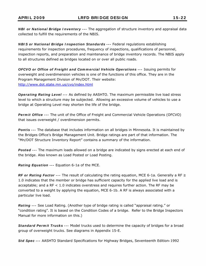
NBI or National Bridge Inventory --- The aggregation of structure inventory and appraisal data collected to fulfill the requirements of the NBIS. NBIS or National Bridge Inspection Standards --- Federal regulations establishing requirements for inspection procedures, frequency of inspections, qualifications of personnel, inspection reports, and preparation and maintenance of bridge inventory records. The NBIS apply to all structures defined as bridges located on or over all public roads. OFCVO or Office of Freight and Commercial Vehicle Operations --- Issuing permits for overweight and overdimension vehicles is one of the functions of this office. They are in the Program Management Division of Mn/DOT. Their website: http://www.dot.state.mn.us/cvo/index.html Operating Rating Level --- As defined by AASHTO. The maximum permissible live load stress level to which a structure may be subjected. Allowing an excessive volume of vehicles to use a bridge at Operating Level may shorten the life of the bridge. Permit Office --- The unit of the Office of Freight and Commercial Vehicle Operations (OFCVO) that issues overweight / overdimension permits. Pontis --- The database that includes information on all bridges in Minnesota. It is maintained by the Bridges Office’s Bridge Management Unit. Bridge ratings are part of that information. The “Mn/DOT Structure Inventory Report” contains a summary of the information. Posted --- The maximum loads allowed on a bridge are indicated by signs erected at each end of the bridge. Also known as Load Posted or Load Posting. Rating Equation --- Equation 6-1a of the MCE. RF or Rating Factor --- The result of calculating the rating equation, MCE 6-1a. Generally a RF ≥ 1.0 indicates that the member or bridge has sufficient capacity for the applied live load and is acceptable; and a RF < 1.0 indicates overstress and requires further action. The RF may be converted to a weight by applying the equation, MCE 6-1b. A RF is always associated with a particular live load. Rating --- See Load Rating. (Another type of bridge rating is called “appraisal rating.” or “condition rating”. It is based on the Condition Codes of a bridge. Refer to the Bridge Inspectors Manual for more information on this.) Standard Permit Trucks --- Model trucks used to determine the capacity of bridges for a broad group of overweight trucks. See diagrams in Appendix 15-E. Std Spec --- AASHTO Standard Specifications for Highway Bridges, Seventeenth Edition-1992

APRIL 2009 LRFD BRIDGE DESIGN 15-23
TH or Trunk Highway --- This consists of all highways under the jurisdiction of the State of Minnesota, including Interstate highways, U. S. highways and Minnesota highways. Type --- Bridge type refers to a brief description of the bridge superstructure. The names and numerical codes for these are found in this manual, Appendix 2-A.
OCTOBER 2011 LRFD BRIDGE DESIGN 15-24
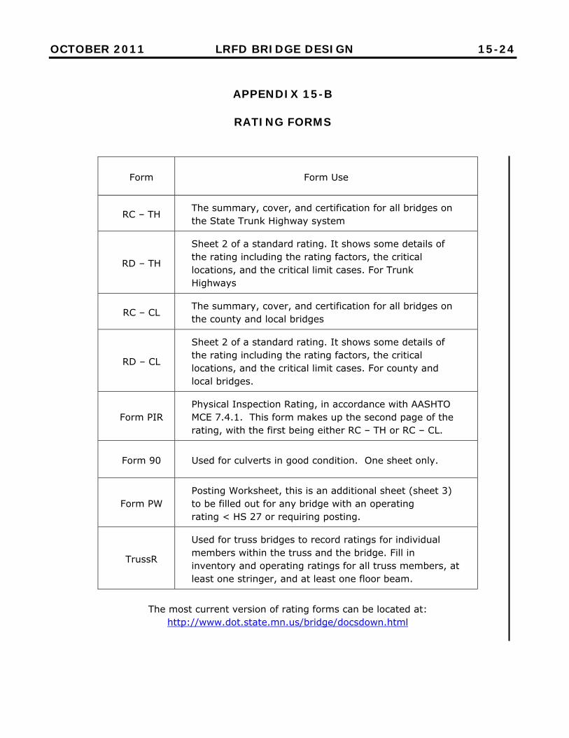
APPENDIX 15-B
RATING FORMS
Form Form Use
RC – TH The summary, cover, and certification for all bridges on the State Trunk Highway system
RD – TH
Sheet 2 of a standard rating. It shows some details of the rating including the rating factors, the critical locations, and the critical limit cases. For Trunk Highways
RC – CL The summary, cover, and certification for all bridges on the county and local bridges
RD – CL
Sheet 2 of a standard rating. It shows some details of the rating including the rating factors, the critical locations, and the critical limit cases. For county and local bridges.
Form PIR Physical Inspection Rating, in accordance with AASHTO MCE 7.4.1. This form makes up the second page of the rating, with the first being either RC – TH or RC – CL.
Form 90 Used for culverts in good condition. One sheet only.
Form PW Posting Worksheet, this is an additional sheet (sheet 3) to be filled out for any bridge with an operating rating < HS 27 or requiring posting.
TrussR
Used for truss bridges to record ratings for individual members within the truss and the bridge. Fill in inventory and operating ratings for all truss members, at least one stringer, and at least one floor beam.
The most current version of rating forms can be located at: http://www.dot.state.mn.us/bridge/docsdown.html
APRIL 2009 LRFD BRIDGE DESIGN 15-25
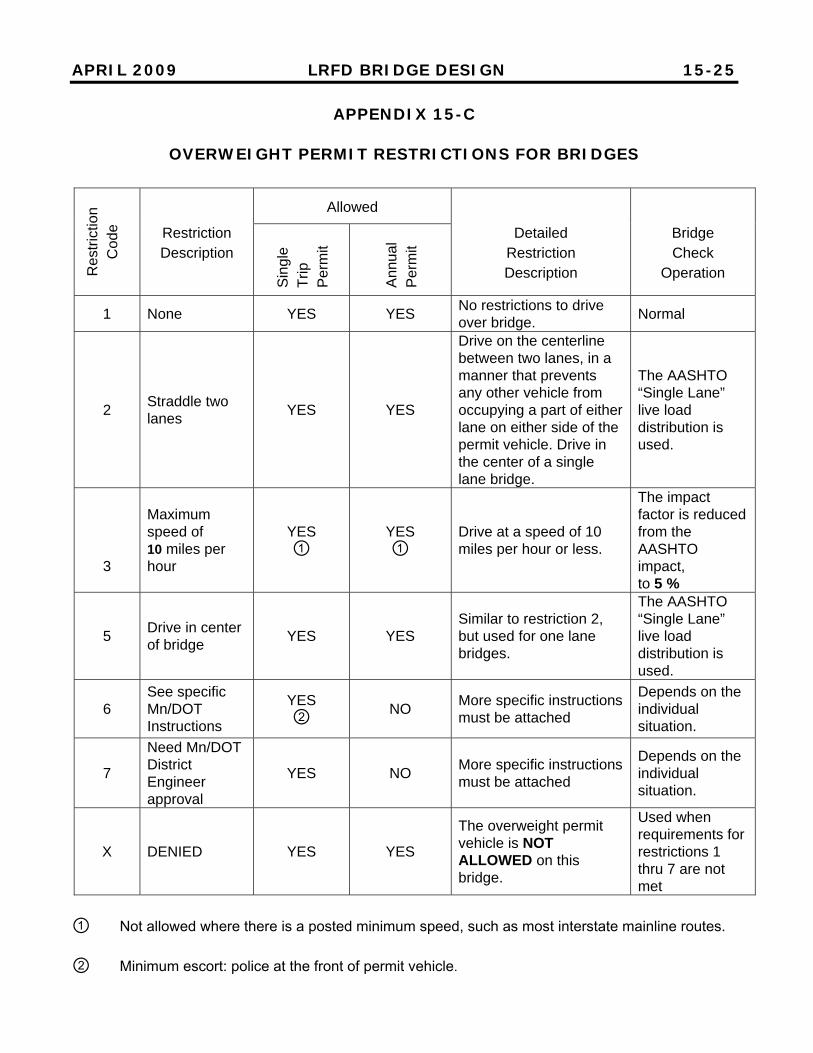
APPENDIX 15-C
OVERWEIGHT PERMIT RESTRICTIONS FOR BRIDGES
① Not allowed where there is a posted minimum speed, such as most interstate mainline routes. ② Minimum escort: police at the front of permit vehicle.
Res
tric
tion
Cod
e Restriction Description
Allowed Detailed
Restriction Description
Bridge Check
Operation S
ingl
e
Trip
P
erm
it
Ann
ual
Per
mit
1 None YES YES No restrictions to drive over bridge.
Normal
2 Straddle two lanes
YES YES
Drive on the centerline between two lanes, in a manner that prevents any other vehicle from occupying a part of either lane on either side of the permit vehicle. Drive in the center of a single lane bridge.
The AASHTO “Single Lane” live load distribution is used.
3
Maximum speed of 10 miles per hour
YES ①
YES ①
Drive at a speed of 10 miles per hour or less.
The impact factor is reduced from the AASHTO impact, to 5 %
5 Drive in center of bridge
YES YES Similar to restriction 2, but used for one lane bridges.
The AASHTO “Single Lane” live load distribution is used.
6 See specific Mn/DOT Instructions
YES ②
NO More specific instructions must be attached
Depends on the individual situation.
7
Need Mn/DOT District Engineer approval
YES NO More specific instructions must be attached
Depends on the individual situation.
X DENIED YES YES
The overweight permit vehicle is NOT ALLOWED on this bridge.
Used when requirements for restrictions 1 thru 7 are not met
OCTOBER 2011 LRFD BRIDGE DESIGN 15-26.1
APPENDIX 15-D
MINNESOTA LEGAL (POSTING) LOADS

OCTOBER 2011 LRFD BRIDGE DESIGN 15-26.2
APPENDIX 15-D (Continued)
MINNESOTA LEGAL (POSTING) LOADS

OCTOBER 2011 LRFD BRIDGE DESIGN 15-26.3
[ This page intentionally left blank ]

APRIL 2009 LRFD BRIDGE DESIGN 15-27
APPENDIX 15-E
MINNESOTA STANDARD PERMIT TRUCKS G-80
APRIL 2009 LRFD BRIDGE DESIGN 15-28
APPENDIX 15-F
MINNESOTA STANDARD PERMIT TRUCKS G-07
APRIL 2009 LRFD BRIDGE DESIGN 15-29
APPENDIX 15-F (Continued)
MINNESOTA STANDARD PERMIT TRUCKS G-07

APRIL 2009 LRFD BRIDGE DESIGN 15-30
[ This page intentionally left blank ]