ddps catalogue
DESCRIPTION
Glass Lined Equipment from DDPSTRANSCRIPT
TECHNICAL DATA PRODUCTSGLASS LINED TECHNOLOGY
P R O C E S S S Y S T E M S
DE DIETRICH
PROCESS SYSTEMS
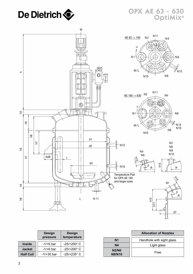
AE 63 -> AE 6300
SSTD-AE-011
DOUBLE-ENVELOPPE
P R O C E S S S Y S T E M S
TECHNICAL DATA PRODUCTS
DE DIETRICH®
reactorsOptiMix® ______________________________________________ 2-7
OPX AE 63 - 630 _____________________________________________________________________________________ 2-3OPX CE 630, OPX BE 1 000 - 4 000 ___________________________________________________________ 4-5OPX BE 6 300 - 40 000 _____________________________________________________________________________ 6-7
DIN Range ___________________________________________ 8-21 A E 63 - 630 ______________________________________________ 8-9 A E 1 000 - 6 300 ___________________________________________ 10-11 B E 1 000 - 6 300 ___________________________________________ 12-13 B E 8 000 - 40 000 _________________________________________ 14-15 C E 630 - 4 000 AN ________________________________________ 16-17 C E 4 000 NN - 8 000 _______________________________________ 18-19 C E 10 000 - 40 000 ________________________________________ 20-21
Half-coil Vessels ____________________________________ 22-23
EURO EZ ____________________________________________ 24-27EZOT 500 - 2 000 _________________________________________________________________________________ 24-25EZWB 2 000 - 6 000 ______________________________________________________________________________ 26-27
Pharma Reactors ____________________________________ 28-29
Laboratory Reactors _______________________________ 30-31
Mixing ______________________________________________ 32-37GlasLock® Selection guide ____________________________________________________________________________ 32GlasLock® Blade data ___________________________________________________________________________________ 33Agitated volumes ____________________________________________________________________________________ 34-35Drive units _____________________________________________________________________________________________ 36-37
equipmentClamped top Receivers RS / RD ________________________ 40
Closed Receivers RFS / RFD ____________________________ 41
Storage Tanks ______________________________________ 42-43
Columns _______________________________________________ 44
Conical Dryers SR _____________________________________ 45
Condensers EC ________________________________________ 46
Heat Exchangers ED ___________________________________ 47
Shell and Tube Heat Exchangers __________________ 48-49
Pipes & Fittings ____________________________________ 50-52
Loose Flanges _________________________________________ 53
Gaskets _______________________________________________ 54
Clamps ________________________________________________ 55
Baffles _________________________________________________ 56
Dip Pipes ______________________________________________ 57
CleanValves ________________________________________ 58-59
h7
h8
h5h1
h4h2
h6h3
h
AxB
d1
d2
h11
h12
d7
R
h13
h13
RR
d4
N 11
Temperature Padfor OPX AE 160and larger sizes
L
N15
N16
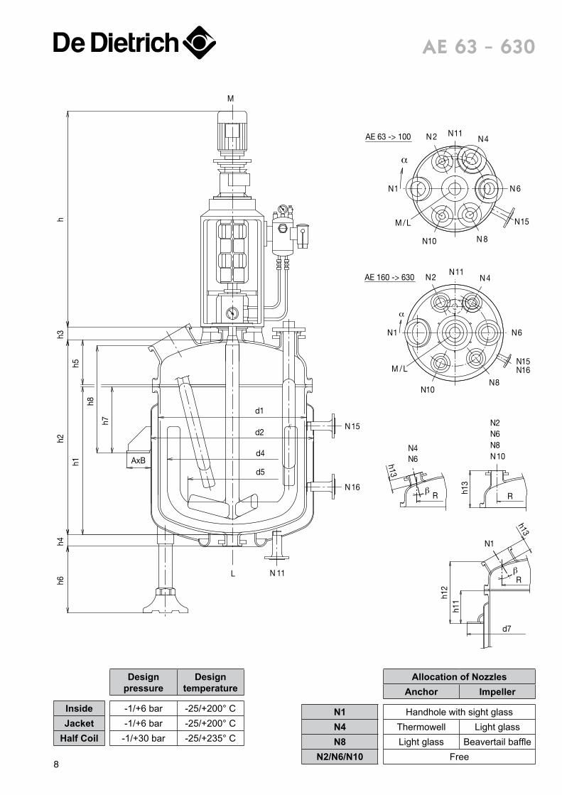
N1
N6N4 N8
N6N2
N10
N1
N2N11
N4
N6
N8
N15N16
N10
M
AE 160 -> 630
f
/LM
/LM
N 1
N 2N11
N 4
N
N15
6
N8N10
AE 63 -> 100
α
α
β
β
h13opX ae 63 - 630
optimix®
Allocation of Nozzles
N1 Handhole with sight glassN4 Light glass
N2/N6 N8/N10 Free
Designpressure
Designtemperature
Inside -1/+6 bar -25/+200° CJacket -1/+6 bar -25/+200° C
Half Coil -1/+30 bar -25/+235° C
2
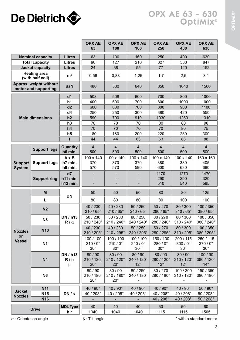
opX ae 63 - 630optimix®
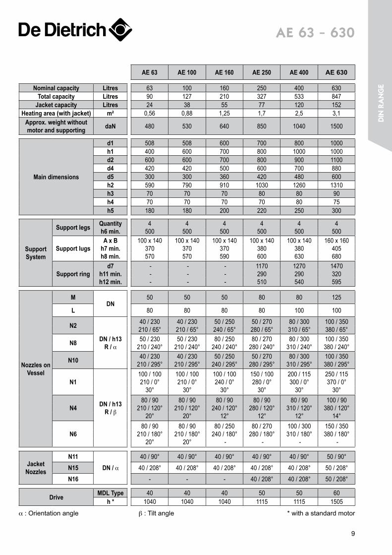
OPX AE 63
OPX AE 100
OPX AE 160
OPX AE 250
OPX AE 400
OPX AE 630
Nominal capacity Litres 63 100 160 250 400 630Total capacity Litres 90 127 210 327 533 847
Jacket capacity Litres 24 38 55 77 120 152Heating area
(with half coil) m² 0,56 0,88 1,25 1,7 2,5 3,1
Approx. weight without motor and supporting daN 480 530 640 850 1040 1500
Main dimensions
d1 508 508 600 700 800 1000h1 400 600 700 800 1000 1000d2 600 600 700 800 900 1100d4 250 250 300 380 420 550h2 590 790 910 1030 1260 1310h3 70 70 70 80 80 90h4 70 70 70 70 80 75h5 180 180 200 220 250 300f 44 44 63 63 88 88
Support System
Support legs Quantityh6 min.
4500
4500
4500
4500
4500
4500
Support lugsA x B
h7 min.h8 min.
100 x 140370570
100 x 140370570
100 x 140370590
100 x 140380600
100 x 140380630
160 x 160405680
Support ringd7
h11 min.h12 min.
- - -
- - -
- - -
1170290510
1270290540
1470320595
Nozzles on
Vessel
MDN
50 50 50 80 80 125
L 80 80 80 80 100 100
N2
DN / h13 R / α
40 / 230210 / 65°
40 / 230210 / 65°
50 / 250240 / 65°
50 / 270280 / 65°
80 / 300310 / 65°
100 / 350380 / 65°
N8 50 / 230210 / 240°
50 / 230210 / 240°
80 / 250240 / 240°
80 / 270280 / 240°
80 / 300310 / 240°
100 / 350380 / 240°
N10 40 / 230210 / 295°
40 / 230210 / 295°
50 / 250240 / 295°
50 / 270280 / 295°
80 / 300310 / 295°
100 / 350380 / 295°
N1
DN / h13 R / α
β
100 / 100210 / 0°
30°
100 / 100210 / 0°
30°
100 / 100240 / 0°
30°
150 / 100280 / 0°
30°
200 / 115300 / 0°
30°
250 / 115370 / 0°
30°
N480 / 90
210 / 120°20°
80 / 90210 / 120°
20°
80 / 90240 / 120°
12°
80 / 90280 / 120°
12°
80 / 90310 / 120°
12°
100 / 90380 / 120°
14°
N680 / 90
210 / 180°20°
80 / 90210 / 180°
20°
80 / 250240 / 180°
-
80 / 270280 / 180°
-
100 / 300310 / 180°
-
150 / 350380 / 180°
-
Jacket Nozzles
N11DN / α
40 / 90° 40 / 90° 40 / 90° 40 / 90° 40 / 90° 50 / 90°N15 40 / 208° 40 / 208° 40 / 208° 40 / 208° 40 / 208° 50 / 208°N16 - - - 40 / 208° 40 / 208° 50 / 208°
Drive MDL Type 40 40 40 50 50 60h * 1040 1040 1040 1115 1115 1505
α : Orientation angle β : Tilt angle * with a standard motor
3
opt
imiX
®
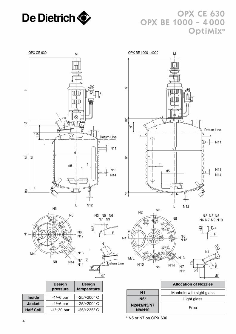
opX ce 630opX Be 1 000 - 4 000
optimix®
d5
hh2
h3h1
Ì
h1
hR
N12L
N13N14
N11
Datum Line
d1
M
500
f
N1
N3
N5
N6N12
N13
N14 N7N11
N9
M/L
h13
N3 N5 N6N7 N9
R
Datum Line
N1
d7
h6h5
N11
N13
N14
N12L
M
d1
d5
f
Datum LinehR
h1h3
h2h
R
h5h6
d7
N1
h13
R
N9N7N6N2 N3 N5
N10
N1
N2N3
N5
N 6N 12
N11N7N9
N10
M/L N13
N 14
α
β
h13
OPX CE 630 OPX BE 1000 - 4000
* N5 or N7 on OPX 630
Allocation of Nozzles
N1 Manhole with sight glassN6* Light glass
N2/N3/N5/N7 N9/N10 Free
Designpressure
Designtemperature
Inside -1/+6 bar -25/+200° CJacket -1/+6 bar -25/+200° C
Half Coil -1/+30 bar -25/+235° C
4
opX ce 630opX Be 1 000 - 4 000
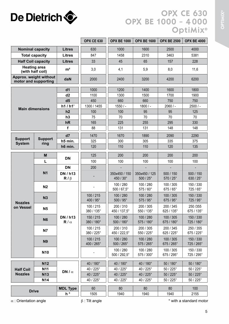
optimix® OPX CE 630 OPX BE 1000 OPX BE 1600 OPX BE 2500 OPX BE 4000
Nominal capacity Litres 630 1000 1600 2500 4000Total capacity Litres 847 1458 2310 3463 5381
Half Coil capacity Litres 33 45 65 157 228Heating area
(with half coil) m² 3,0 4,1 5,9 8,0 11,6
Approx. weight without motor and supporting daN 2000 2400 3200 4200 6200
Main dimensions
d1 1000 1200 1400 1600 1800d2 1100 1300 1500 1700 1900d5 450 660 660 750 750
h1 / h1’ 1300 / 1455 1550 / - 1800 / - 2060 / - 2500 / -h2 100 100 95 95 125h3 75 70 70 70 70hR 165 225 255 295 330f 88 131 131 148 148
Support System
Support ring
d7 1470 1670 1890 2090 2290h5 min. 325 300 305 335 375h6 min. 120 110 110 120 135
Nozzles on Vessel
MDN
125 200 200 200 200L 100 100 100 100 100
N1DN 200 - - - -
DN / h13 R / β - 350x450 / 150
450 / 30°350x450 / 125
500 / 25°500 / 150570 / 25°
500 / 150630 / 25°
N2
DN / h13 R / α
- 100 / 280500 / 67,5°
100 / 280575 / 60°
100 / 305675 / 65°
150 / 330725 / 65°
N3 100 / 215400 / 95°
100 / 280500 / 95°
100 / 280575 / 95°
100 / 305675 / 95°
150 / 330725 / 95°
N5 100 / 215380 / 135°
200 / 310450 / 137,5°
200 / 305550 / 135°
200 / 345625 / 135°
250 /355675 / 135°
N6 150 / 215380 / 180°
100 / 280500 / 180°
100 / 280575 / 180°
100 / 305675 / 180°
150 / 330725 / 180°
N7 100 / 215380 / 225°
200 / 310450 / 222,5°
200 / 305550 / 225°
200 / 345625 / 225°
250 / 355675 / 225°
N9 100 / 215400 / 265°
100 / 280500 / 265°
100 / 280575 / 265°
100 / 305675 / 265°
150 / 330725 / 265°
N10 - 100 / 280500 / 292,5°
100 / 280575 / 300°
100 / 305675 / 295°
150 / 330725 / 295°
Half Coil Nozzles
N12
DN / α
40 / 180° 40 / 180° 40 / 180° 50 / 180° 50 / 180°N11 40 / 225° 40 / 225° 40 / 225° 50 / 225° 50 / 225°N13 40 / 225° 40 / 225° 40 / 225° 50 / 225° 50 / 225°N14 40 / 225° 40 / 225° 40 / 225° 50 / 225° 50 / 225°
DriveMDL Type 60 80 80 80 100
h * 1505 1940 1940 1940 2155
α : Orientation angle β : Tilt angle * with a standard motor
5
opt
imiX
®
N 14
N 13
N 11
N 12L
M
hR
h2h1
h3h
Datum Line
d1
d5
f
d7
R
R
h13h6
h5
N1
N6 N7 N9
N2
N10
N3 N5β
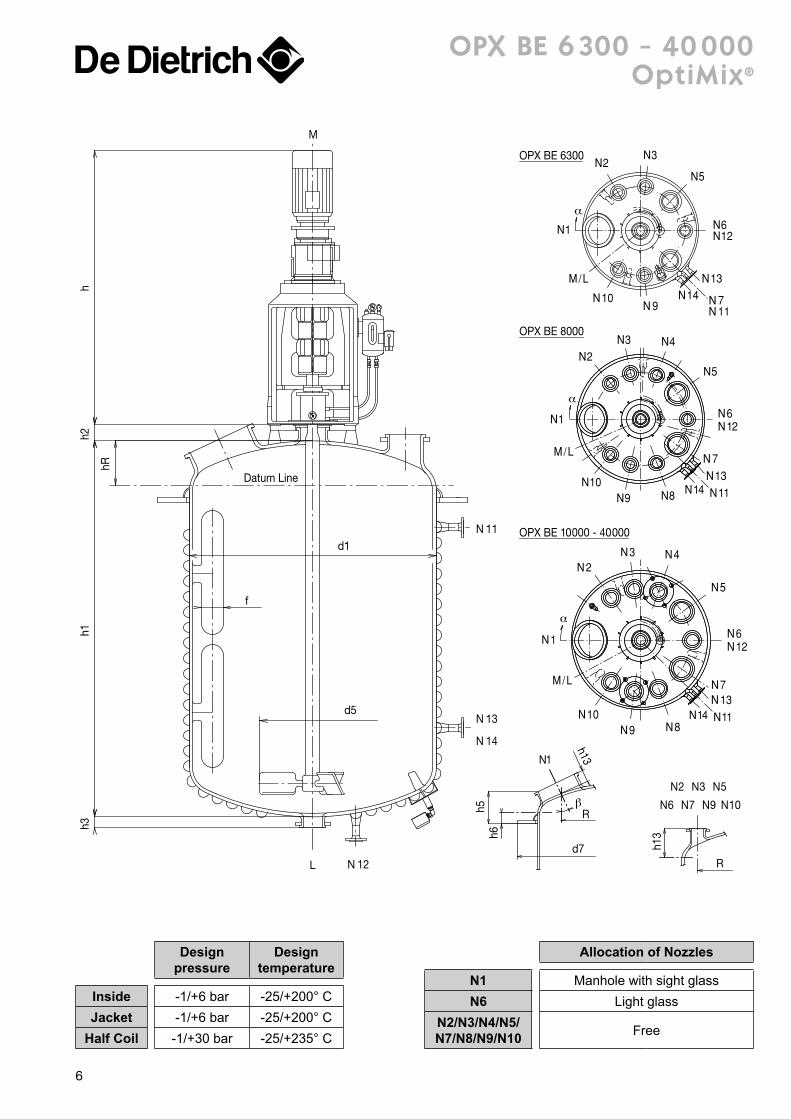
OPX BE 6300
OPX BE 8000
OPX BE 10000 - 40000
h13
M/L
M/L
M/L
13N14N
9N10N 7N
11N
6N12N
5N
3N
3N 4N
5N
6N12N
7N
8N9N10N
1N
2N
2N
1N
α
α
13N11N14N
3N 4N
5N
6N12N
7N
8N9N10N
N1
2N
α
13N14N 11N
opX Be 6 300 - 40 000optimix®
Allocation of Nozzles
N1 Manhole with sight glassN6 Light glass
N2/N3/N4/N5/N7/N8/N9/N10 Free
Designpressure
Designtemperature
Inside -1/+6 bar -25/+200° CJacket -1/+6 bar -25/+200° C
Half Coil -1/+30 bar -25/+235° C
6
opX Be 6 300 - 40 000optimix®
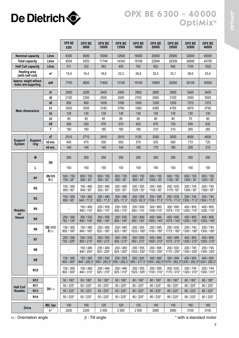
OPX BE 6300
OPX BE 8000
OPX BE 10000
OPX BE 12500
OPX BE 16000
OPX BE 20000
OPX BE 25000
OPX BE 32000
OPX BE 40000
Nominal capacity Litres 6300 8000 10000 12500 16000 20000 25000 32000 40000Total capacity Litres 8204 9353 11749 14340 18169 22649 28309 36690 44700
Half Coil capacity Litres 311 322 363 455 763 922 942 1100 1522Heating area
(with half coil) m² 15,9 16,4 18,6 23,3 26,8 32,4 33,1 38,6 53,4
Approx. weight without motor and supporting daN 7700 8600 11600 13100 16100 18900 22000 30100 34500
Main dimensions
d1 2000 2200 2400 2400 2600 2800 3000 3400 3400d2 2100 2300 2500 2500 2700 2900 3100 3550 3550d5 850 850 1050 1050 1050 1200 1200 1372 1372h1 3050 3000 3180 3780 1080 4385 4755 4875 5795h2 125 130 135 130 130 135 135 135 135h3 85 85 85 85 80 80 80 70 80hR 365 520 570 570 620 670 720 835 835f 180 180 185 185 185 210 210 265 265
Support System
Support ring
d7 2510 2710 2910 2910 3120 3350 3550 4000 4000h5 min. 405 475 500 500 575 535 560 715 725h6 min. 140 145 145 145 165 175 180 205 215
Nozzles on
Vessel
MDN
200 200 250 250 250 300 300 300 300
L 150 150 150 150 150 150 150 150 150
N1 DN / h13 R / β
500 / 150700 / 25°
600 / 150800 / 30°
600 / 150850 / 30°
600 / 150850 / 30°
600 / 150900 / 30°
600 / 1501000 / 30°
600 / 1501100 / 30°
600 / 1501250 / 30°
600 / 1501250 / 30°
N2
DN / h13 R / α
150 / 365800 / 60°
150 / 480840 / 50°
200 / 480925 / 50°
200 / 480925 / 50°
200 / 5551025 / 55°
200 / 5951100 / 50°
200 / 6301175 / 50°
200 / 7451300 / 50°
200 / 7451300 / 50°
N3 150 / 365800 / 95°
150 / 480840 / 77,5°
200 / 480925 / 77,5°
200 / 480925 / 77,5°
200 / 5551025 / 82,5°
200 / 5951100 / 77,5°
200 / 6301175 / 77,5°
200 / 7451300 / 77,5°
200 / 7451300 / 77,5°
N4 - 150 / 480840 / 110°
250 / 555900 / 110°
250 / 555900 / 110°
250 / 600950 / 110°
300 / 6651000 /110°
300 / 6901075 / 110°
400 / 8051200 / 110°
400 / 8051200 / 110°
N5 250 / 390750 / 135°
300 / 530800 / 145°
300 / 555900 / 145°
300 / 555900 / 145°
300 / 600950 / 145°
400 / 6651000 / 145°
400 / 6901075 / 145°
400 / 8051200 / 145°
400 / 8051200 / 145°
N6 150 / 365800 / 180°
150 / 480840 / 180°
200 / 480925 / 180°
200 / 480925 / 180°
200 / 5551025 / 180°
200 / 5951100 / 180°
200 / 6301175 / 180°
200 / 7451300 / 180°
200 / 7451300 / 180°
N7 250 / 390750 / 225°
300 / 530800 / 215°
300 / 555900 / 215°
300 / 555900 / 215°
300 / 600950 / 215°
400 / 6651000 / 215°
400 / 6901075 / 215°
400 / 8051200 / 215°
400 / 8051200 / 215°
N8 - 150 / 480840 / 250°
200 / 480925 / 250°
200 / 480925 / 250°
200 / 5551025 / 250°
200 / 5951100 / 250°
200 / 6301175 / 250°
200 / 7451300 / 250°
200 / 7451300 / 250°
N9 150 / 365800 / 265°
150 / 480840 / 282,5°
250 / 555900 / 282,5°
250 / 555900 / 282,5°
250 / 600950 / 277,5°
300 / 6651000 / 282,5°
300 / 6901075 / 282,5°
400 / 8051200 / 282,5°
400 / 8051200 / 282,5°
N10 150 / 365800 / 300°
150 / 480840 / 310°
200 / 480925 / 310°
200 / 480925 / 310°
200 / 5551025 / 305°
200 / 5951100 / 310°
200 / 6301175 / 310°
200 / 7451300 / 310°
200 / 7451300 / 310°
Half Coil Nozzles
N12
DN / α
50 / 180° 50 / 180° 50 / 180° 50 / 180° 80 / 180° 80 / 180° 80 / 180° 80 / 180° 80 / 180°N11 50 / 225° 50 / 225° 50 / 225° 50 / 225° 80 / 225° 80 / 225° 80 / 225° 80 / 225° 80 / 225°N13 50 / 225° 50 / 225° 50 / 225° 50 / 225° 80 / 225° 80 / 225° 80 / 225° 80 / 225° 80 / 225°
N14 50 / 225° 50 / 225° 50 / 225° 50 / 225° 80 / 225° 80 / 225° 80 / 225° 80 / 225° 80 / 225°
DriveMDL Type 100 100 125 125 125 140 140 160 160
h * 2200 2200 2 500 2 500 2 500 2680 2680 3100 3100
α : Orientation angle β : Tilt angle * with a standard motor
7
opt
imiX
®
h11
h12
d7
R
h13
h13
RR
N1
N6N4 N8
N6N2
N10
h13
h7
h8
h5h1
h4h2
h6h3
h
AxB
d1
d2
d4
d5
N 11L
N15
N16
M
N1
N2N11
N4
N6
N8
N15N16
N10
/ LM
AE 160 -> 630
/ LM
N1
N 2 N11N4
N
N15
6
N 8N10
AE 63 -> 100
α
α
β
β
ae 63 - 630
Designpressure
Designtemperature
Inside -1/+6 bar -25/+200° CJacket -1/+6 bar -25/+200° C
Half Coil -1/+30 bar -25/+235° C
Allocation of NozzlesAnchor Impeller
N1 Handhole with sight glassN4 Thermowell Light glassN8 Light glass Beavertail baffle
N2/N6/N10 Free8
ae 63 - 630
AE 63 AE 100 AE 160 AE 250 AE 400 AE 630
Nominal capacity Litres 63 100 160 250 400 630Total capacity Litres 90 127 210 327 533 847
Jacket capacity Litres 24 38 55 77 120 152Heating area (with jacket) m² 0,56 0,88 1,25 1,7 2,5 3,1
Approx. weight without motor and supporting daN 480 530 640 850 1040 1500
Main dimensions
d1 508 508 600 700 800 1000h1 400 600 700 800 1000 1000d2 600 600 700 800 900 1100d4 420 420 500 600 700 880d5 300 300 360 420 480 600h2 590 790 910 1030 1260 1310h3 70 70 70 80 80 90h4 70 70 70 70 80 75h5 180 180 200 220 250 300
Support System
Support legs Quantityh6 min.
4500
4500
4500
4500
4500
4500
Support lugsA x B
h7 min.h8 min.
100 x 140370570
100 x 140370570
100 x 140370590
100 x 140380600
100 x 140380630
160 x 160405680
Support ringd7
h11 min.h12 min.
- - -
- - -
- - -
1170290510
1270290540
1470320595
Nozzles on Vessel
MDN
50 50 50 80 80 125
L 80 80 80 80 100 100
N2
DN / h13 R / α
40 / 230210 / 65°
40 / 230210 / 65°
50 / 250240 / 65°
50 / 270280 / 65°
80 / 300310 / 65°
100 / 350380 / 65°
N8 50 / 230210 / 240°
50 / 230210 / 240°
80 / 250240 / 240°
80 / 270280 / 240°
80 / 300310 / 240°
100 / 350380 / 240°
N10 40 / 230210 / 295°
40 / 230210 / 295°
50 / 250240 / 295°
50 / 270280 / 295°
80 / 300310 / 295°
100 / 350380 / 295°
N1
DN / h13 R / β
100 / 100210 / 0°
30°
100 / 100210 / 0°
30°
100 / 100240 / 0°
30°
150 / 100280 / 0°
30°
200 / 115300 / 0°
30°
250 / 115370 / 0°
30°
N480 / 90
210 / 120°20°
80 / 90210 / 120°
20°
80 / 90240 / 120°
12°
80 / 90280 / 120°
12°
80 / 90310 / 120°
12°
100 / 90380 / 120°
14°
N680 / 90
210 / 180°20°
80 / 90210 / 180°
20°
80 / 250240 / 180°
-
80 / 270280 / 180°
-
100 / 300310 / 180°
-
150 / 350380 / 180°
-
Jacket Nozzles
N11DN / α
40 / 90° 40 / 90° 40 / 90° 40 / 90° 40 / 90° 50 / 90°
N15 40 / 208° 40 / 208° 40 / 208° 40 / 208° 40 / 208° 50 / 208°
N16 - - - 40 / 208° 40 / 208° 50 / 208°
Drive MDL Type 40 40 40 50 50 60h * 1040 1040 1040 1115 1115 1505
α : Orientation angle β : Tilt angle * with a standard motor
9
Din
ra
nge
AxB
h7
h8
h5h1
h2h3
hh4
h6
d1
d2
d4
d5
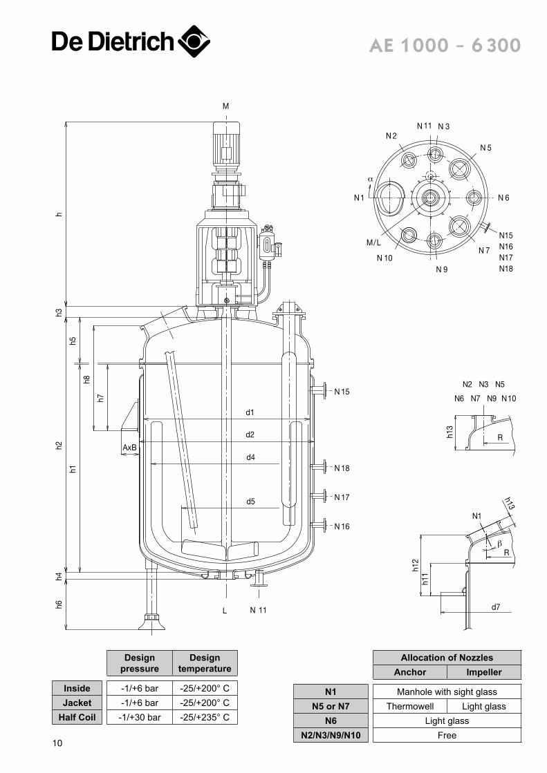
N 15
N 18
N 17
N 16
L N 11
M
N1
N 2N 11 N 3
N 5
N 6
N 7
N 9N 10
/LN15N16N17N18
M
h11
h12
R
Rh13
d7
N2 N3 N5
N7 N9N6 N10
N1
α
β
h13
ae 1 000 - 6 300
Designpressure
Designtemperature
Inside -1/+6 bar -25/+200° CJacket -1/+6 bar -25/+200° C
Half Coil -1/+30 bar -25/+235° C
Allocation of NozzlesAnchor Impeller
N1 Manhole with sight glassN5 or N7 Thermowell Light glass
N6 Light glassN2/N3/N9/N10 Free
10
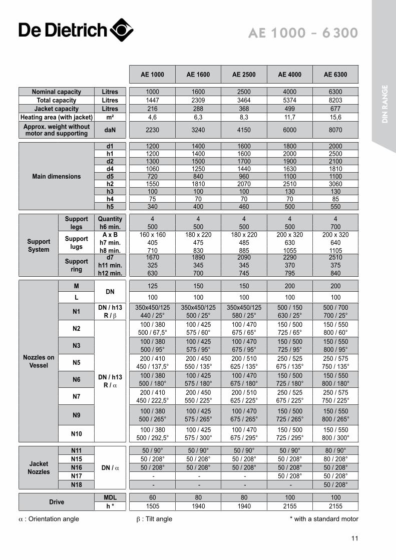
ae 1 000 - 6 300
AE 1000 AE 1600 AE 2500 AE 4000 AE 6300
Nominal capacity Litres 1000 1600 2500 4000 6300Total capacity Litres 1447 2309 3464 5374 8203
Jacket capacity Litres 216 288 368 499 677Heating area (with jacket) m² 4,6 6,3 8,3 11,7 15,6Approx. weight without motor and supporting daN 2230 3240 4150 6000 8070
Main dimensions
d1 1200 1400 1600 1800 2000h1 1200 1400 1600 2000 2500d2 1300 1500 1700 1900 2100d4 1060 1250 1440 1630 1810d5 720 840 960 1100 1100h2 1550 1810 2070 2510 3060h3 100 100 100 130 130h4 75 70 70 70 85h5 340 400 460 500 550
Support System
Support legs
Quantityh6 min.
4500
4500
4500
4500
4700
Support lugs
A x Bh7 min.h8 min.
160 x 160405710
180 x 220475830
180 x 220485885
200 x 320630
1055
200 x 3206401105
Support ring
d7h11 min.h12 min.
1670325630
1890345700
2090345745
2290370795
2510375840
Nozzles on Vessel
MDN
125 150 150 200 200
L 100 100 100 100 100
N1 DN / h13 R / β
350x450/125440 / 25°
350x450/125500 / 25°
350x450/125580 / 25°
500 / 150630 / 25°
500 / 700700 / 25°
N2
DN / h13R / α
100 / 380500 / 67,5°
100 / 425575 / 60°
100 / 470675 / 65°
150 / 500725 / 65°
150 / 550800 / 60°
N3 100 / 380500 / 95°
100 / 425575 / 95°
100 / 470675 / 95°
150 / 500725 / 95°
150 / 550800 / 95°
N5 200 / 410450 / 137,5°
200 / 450550 / 135°
200 / 510625 / 135°
250 / 525675 / 135°
250 / 575750 / 135°
N6 100 / 380500 / 180°
100 / 425575 / 180°
100 / 470675 / 180°
150 / 500725 / 180°
150 / 550800 / 180°
N7 200 / 410450 / 222,5°
200 / 450550 / 225°
200 / 510625 / 225°
250 / 525675 / 225°
250 / 575750 / 225°
N9 100 / 380500 / 265°
100 / 425575 / 265°
100 / 470675 / 265°
150 / 500725 / 265°
150 / 550800 / 265°
N10 100 / 380500 / 292,5°
100 / 425575 / 300°
100 / 470675 / 295°
150 / 500725 / 295°
150 / 550800 / 300°
Jacket Nozzles
N11
DN / α
50 / 90° 50 / 90° 50 / 90° 50 / 90° 80 / 90°N15 50 / 208° 50 / 208° 50 / 208° 50 / 208° 80 / 208°N16 50 / 208° 50 / 208° 50 / 208° 50 / 208° 50 / 208°N17 - - - 50 / 208° 50 / 208°N18 - - - - 50 / 208°
Drive MDL 60 80 80 100 100h * 1505 1940 1940 2155 2155
α : Orientation angle β : Tilt angle * with a standard motor
11
Din
ra
nge
N 16
N 17
N 15
N 11L
M
AxB
h6
h5hR
h2h1
h3h4
h
Datum Line
h9h1
0
d7
R
d1
d2
d5
R
h13
N1
N6 N7 N9
N2
N10
N3 N5
N 1
N 2N 3N 11
N 5
N 6
N15N16N17N18
N 7
N 9N 10
/LM
N 18
α
β
h13
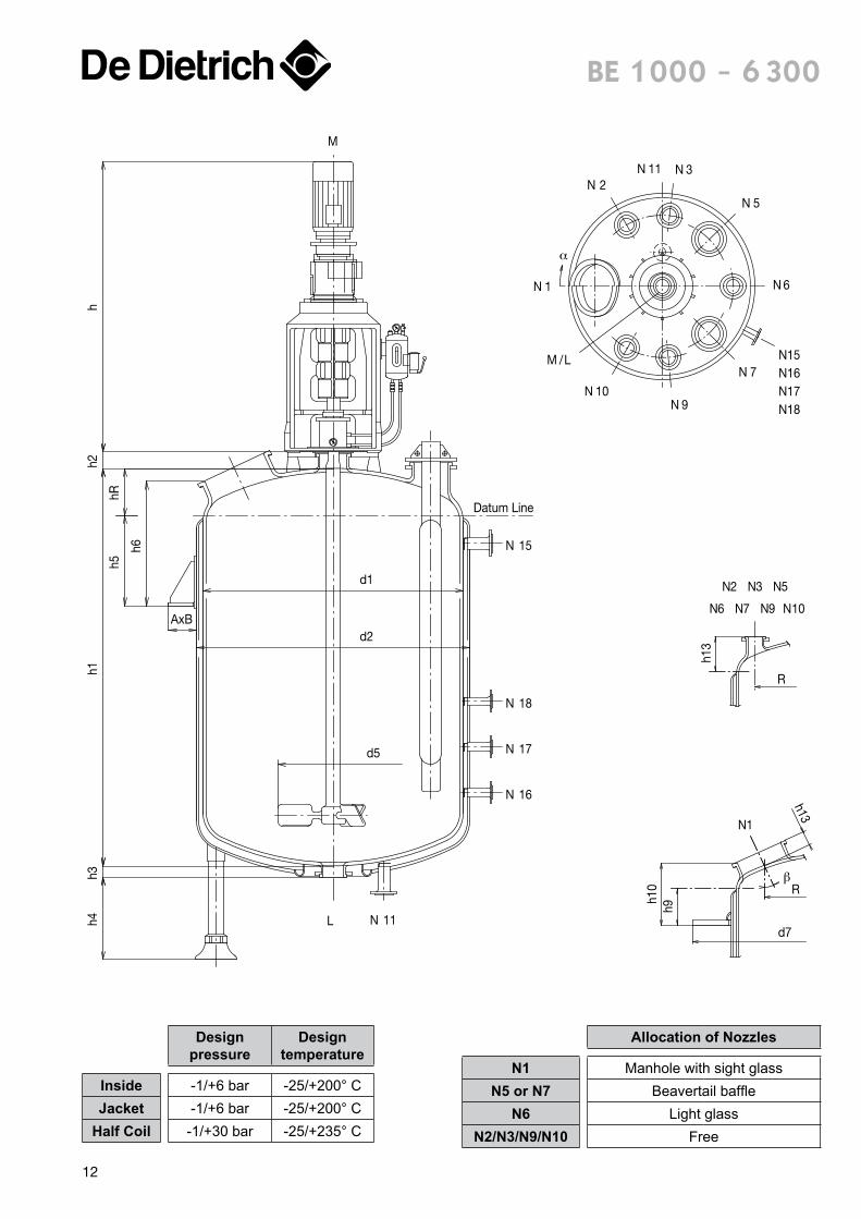
Be 1 000 - 6 300
Designpressure
Designtemperature
Inside -1/+6 bar -25/+200° CJacket -1/+6 bar -25/+200° C
Half Coil -1/+30 bar -25/+235° C
Allocation of Nozzles
N1 Manhole with sight glassN5 or N7 Beavertail baffle
N6 Light glassN2/N3/N9/N10 Free
12
Be 1 000 - 6 300
BE 1000 BE 1600 BE 2500 BE 4000 BE 6300
Nominal capacity Litres 1000 1600 2500 4000 6300Total capacity Litres 1458 2310 3463 5381 8204
Jacket capacity Litres 249 333 422 560 712Heating area (with jacket) m² 5,4 7,3 9,7 13,4 18,1Approx. weight without motor and supporting daN 2400 3200 4200 6200 7700
Main dimensions
d1 1200 1400 1600 1800 2000d2 1300 1500 1700 1900 2100d5 660 660 750 750 850h1 1550 1800 2060 2500 3050h2 100 100 100 130 130h3 75 70 70 70 85hR 225 255 295 330 365
Support System
Support legs Quantityh4
4500
4500
4500
4500
4700
Support lugsA x B
h5 min.h6 min.
160 x 160320510
180 x 220380580
180 x 220380600
200 x 320545790
200 x 320535800
Support ringd7
h9 min.h10 min.
1670310500
1890240440
2090240460
2290250495
2510270535
Nozzles on Vessel
MDN
200 200 200 200 200
L 100 100 100 100 150
N1 DN / h13 R / β
350x450 / 150450 / 30°
350x450 / 125500 / 25°
500 / 150570 / 25°
500 / 150630 / 25°
500 / 150700 / 25°
N2
DN / h13R / α
100 / 280500 / 67,5°
100 / 280575 / 60°
100 / 305675 / 65°
150 / 330725 / 65°
150 / 365800 / 60°
N3 100 / 280500 / 95°
100 / 280575 / 95°
100 / 305675 / 95°
150 / 330725 / 95°
150 / 365800 / 95°
N5 200 / 310450 / 137,5°
200 / 305550 / 135°
200 / 345625 / 135°
250 /355675 / 135°
250 / 390750 / 135°
N6 100 / 280500 / 180°
100 / 280575 / 180°
100 / 305675 / 180°
150 / 330725 / 180°
150 / 365800 / 180°
N7 200 / 310450 / 222,5°
200 / 305550 / 225°
200 / 345625 / 225°
250 / 355675 / 225°
250 / 390750 / 225°
N9 100 / 280500 / 265°
100 / 280575 / 265°
100 / 305675 / 265°
150 / 330725 / 265°
150 / 365800 / 265°
N10 100 / 280500 / 292,5°
100 / 280575 / 300°
100 / 305675 / 295°
150 / 330725 / 295°
150 / 365800 / 300°
Jacket Nozzles
N11
DN / α
50 / 90° 50 / 90° 50 / 90° 50 / 90° 80 / 90°N15 50 / 208° 50 / 208° 50 / 208° 50 / 208° 80 / 208°N16 50 / 208° 50 / 208° 50 / 208° 50 / 208° 50 / 208°N17 - - - 50 / 208° 50 / 208°N18 - - - - 50 / 208°
Drive MDL Type 80 80 80 100 100h * 1725 1790 1940 2155 2155
α : Orientation angle β : Tilt angle * with a standard motor13
Din
ra
nge
N 16
N 17
N 18
N 19
N 15
N 11L
M
AxB
h6
h5hR
h1h3
hh2
d1
d2
d5
h4
h9h1
0
d7
R
R
h13
N2 N3 N4 N5
N6 N7 N8 N9 N 10
N1
β
N1
N 2N 3 N 4N 11
N 5
N 6
N15N16N17N18N19
N15N16N17N18N19
N 7
N8N9N 10
/LM
α
N1
N 2N 3 N 4N 11
N 5
N 6
N 7
N8N9N 10
/LM
α
h13
Datum Line
BE 10000 - BE 40000
BE 8000
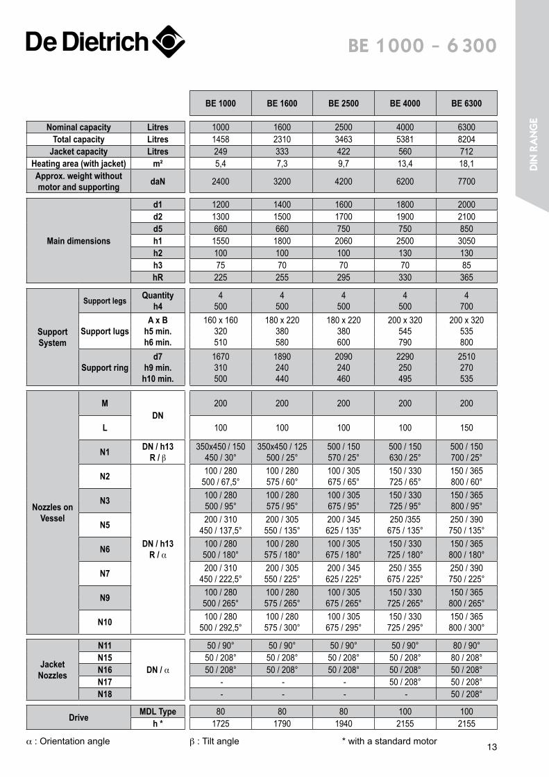
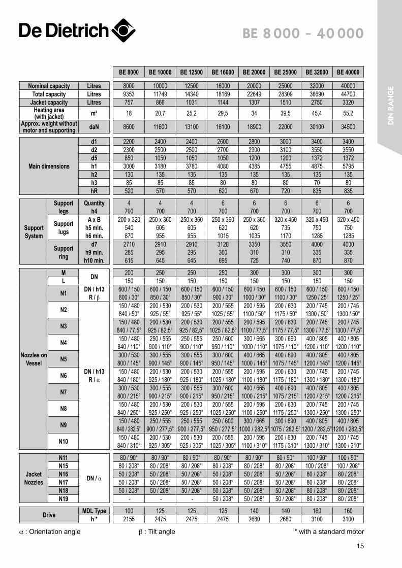
Be 8 000 - 40 000
Designpressure
Designtemperature
Inside -1/+6 bar -25/+200° CJacket -1/+6 bar -25/+200° C
Half Coil -1/+30 bar -25/+235° C
Allocation of Nozzles
N1 Manhole with sight glassN4 or N9* Beavertail baffle
N6 Light glassN2/N3/N5/N7
N8/N10 Free
* N5 or N7 for BE 800014
Be 8 000 - 40 000
BE 8000 BE 10000 BE 12500 BE 16000 BE 20000 BE 25000 BE 32000 BE 40000
Nominal capacity Litres 8000 10000 12500 16000 20000 25000 32000 40000Total capacity Litres 9353 11749 14340 18169 22649 28309 36690 44700
Jacket capacity Litres 757 866 1031 1144 1307 1510 2750 3320Heating area (with jacket) m² 18 20,7 25,2 29,5 34 39,5 45,4 55,2
Approx. weight without motor and supporting daN 8600 11600 13100 16100 18900 22000 30100 34500
Main dimensions
d1 2200 2400 2400 2600 2800 3000 3400 3400d2 2300 2500 2500 2700 2900 3100 3550 3550d5 850 1050 1050 1050 1200 1200 1372 1372h1 3000 3180 3780 4080 4385 4755 4875 5795h2 130 135 135 135 135 135 135 135h3 85 85 85 80 80 80 70 80hR 520 570 570 620 670 720 835 835
Support System
Support legs
Quantityh4
4700
4700
4700
6700
6700
6700
6700
6700
Support lugs
A x Bh5 min.h6 min.
200 x 320540870
250 x 360605955
250 x 360605955
250 x 3606201015
250 x 3606201035
320 x 4507351170
320 x 4507501285
320 x 4507501285
Support ring
d7h9 min.h10 min.
2710285615
2910295645
2910295645
3120300695
3350310725
3550310740
4000335870
4000335870
Nozzles on Vessel
M DN 200 250 250 250 300 300 300 300L 150 150 150 150 150 150 150 150
N1 DN / h13 R / β
600 / 150800 / 30°
600 / 150850 / 30°
600 / 150850 / 30°
600 / 150900 / 30°
600 / 1501000 / 30°
600 / 1501100 / 30°
600 / 1501250 / 25°
600 / 1501250 / 25°
N2
DN / h13 R / α
150 / 480840 / 50°
200 / 530925 / 55°
200 / 530925 / 55°
200 / 5551025 / 55°
200 / 5951100 / 50°
200 / 6301175 / 50°
200 / 7451300 / 50°
200 / 7451300 / 50°
N3 150 / 480840 / 77,5°
200 / 530925 / 82,5°
200 / 530925 / 82,5°
200 / 5551025 / 82,5°
200 / 5951100 / 77,5°
200 / 6301175 / 77,5°
200 / 7451300 / 77,5°
200 / 7451300 / 77,5°
N4 150 / 480840 / 110°
250 / 555900 / 110°
250 / 555900 / 110°
250 / 600950 / 110°
300 / 6651000 / 110°
300 / 6901075 / 110°
400 / 8051200 / 110°
400 / 8051200 / 110°
N5 300 / 530800 / 145°
300 / 555900 / 145°
300 / 555900 / 145°
300 / 600950 / 145°
400 / 6651000 / 145°
400 / 6901075 / 145°
400 / 8051200 / 145°
400 / 8051200 / 145°
N6 150 / 480840 / 180°
200 / 530925 / 180°
200 / 530925 / 180°
200 / 5551025 / 180°
200 / 5951100 / 180°
200 / 6301175 / 180°
200 / 7451300 / 180°
200 / 7451300 / 180°
N7 300 / 530800 / 215°
300 / 555900 / 215°
300 / 555900 / 215°
300 / 600950 / 215°
400 / 6651000 / 215°
400 / 6901075 / 215°
400 / 8051200 / 215°
400 / 8051200 / 215°
N8 150 / 480840 / 250°
200 / 530925 / 250°
200 / 530925 / 250°
200 / 5551025 / 250°
200 / 5951100 / 250°
200 / 6301175 / 250°
200 / 7451300 / 250°
200 / 7451300 / 250°
N9 150 / 480840 / 282,5°
250 / 555900 / 277,5°
250 / 555900 / 277,5°
250 / 600950 / 277,5°
300 / 6651000 / 282,5°
300 / 6901075 / 282,5°
400 / 8051200 / 282,5°
400 / 8051200 / 282,5°
N10 150 / 480840 / 310°
200 / 530925 / 305°
200 / 530925 / 305°
200 / 5551025 / 305°
200 / 5951100 / 310°
200 / 6301175 / 310°
200 / 7451300 / 310°
200 / 7451300 / 310°
Jacket Nozzles
N11
DN / α
80 / 90° 80 / 90° 80 / 90° 80 / 90° 80 / 90° 80 / 90° 100 / 90° 100 / 90°N15 80 / 208° 80 / 208° 80 / 208° 80 / 208° 80 / 208° 80 / 208° 100 / 208° 100 / 208°N16 50 / 208° 50 / 208° 50 / 208° 50 / 208° 50 / 208° 50 / 208° 80 / 208° 80 / 208°N17 50 / 208° 50 / 208° 50 / 208° 50 / 208° 50 / 208° 50 / 208° 80 / 208° 80 / 208°N18 50 / 208° 50 / 208° 50 / 208° 50 / 208° 50 / 208° 50 / 208° 80 / 208° 80 / 208°N19 - - - 50 / 208° 50 / 208° 50 / 208° 80 / 208° 80 / 208°
Drive MDL Type 100 125 125 125 140 140 160 160h * 2155 2475 2475 2475 2680 2680 3100 3100
α : Orientation angle β : Tilt angle * with a standard motor
15
Din
ra
nge
AxB
h7
Datum Line
hR
h8
h6h4
h1
h2h3
h
d1
d2
d5
M
N15
N16
N17
N 11L
h11
h12
d7
N1
R
h13
N 7 N 9N 6
N 2 N 3 N 5
N10
N1
N2N11 N3
N5
N6
N7
N9N 10
N15N16N17
M / L
N1
N11 N3
N5
N 6
N15N 7
N9
N16M / L
CE 2500 - 4000AN
CE 630-1600
d4
α
α
d6
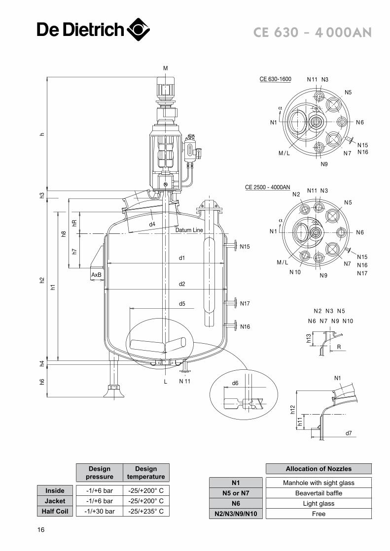
ce 630 - 4 000an
Designpressure
Designtemperature
Inside -1/+6 bar -25/+200° CJacket -1/+6 bar -25/+200° C
Half Coil -1/+30 bar -25/+235° C
Allocation of Nozzles
N1 Manhole with sight glassN5 or N7 Beavertail baffle
N6 Light glassN2/N3/N9/N10 Free
16

ce 630 - 4 000an
CE 630 CE 1600 CE 2500 CE 4000AN
Nominal capacity Litres 630 1600 2500 4000Total capacity Litres 847 2033 3079 4888
Jacket capacity Litres 182 299 382 515Heating area (with jacket) m² 3,9 6,5 8,7 12,2
Approx. weight without motor and supporting daN 2000 3050 4000 5600
Main dimensions
d1 1000 1400 1600 1800h1 1300 1611 1859 2297d2 1100 1500 1700 1900d4 500 770 770 770d5 600 840 960 1100d6 600 660 750 750h2 1455 1810 2070 2510h3 100 115 115 115h4 75 75 70 70hR 165 255 295 330
Support system
Support legs Quantityh6 min.
4500
4500
4500
4500
Support lugsA x B
h7 min.h8 min.
160 x 160340720
180 x 220380830
180 x 220380885
200 x 3205451085
Support ringd7
h11 min.h12 min.
1440240620
1890240690
2090240745
2290250795
Nozzles on vessel
MDN
125 150 150 150L 100 100 100 100
N1 200 350 / 450 350 / 450 350 / 450
N2
DN / h13 R / α
- - 100 / 305675 / 65°
150 / 330725 / 65°
N3 100 / 215400 / 95°
100 / 280575 / 95°
100 / 305675 / 95°
150 / 330725 / 95°
N5 100 / 215380 / 135°
200 / 305550 / 135°
200 / 345625 / 135°
250 / 355675 / 135°
N6 150 / 215380 / 180°
100 / 280575 / 180°
100 / 305675 / 180°
150 / 330725 / 180°
N7 100 / 215380 / 225°
200 / 305550 / 225°
200 / 345625 / 225°
250 / 355675 / 225°
N9 100 / 215400 / 265°
100 / 280575 / 265°
100 / 305675 / 265°
150 / 330725 / 265°
N10 - - 100 / 305675 / 295°
150/ 330725 / 295°
Jacket Nozzles
N11
DN / α
50 / 90° 50 / 90° 50 / 90° 50 / 90°N15 50 / 208° 50 / 208° 50 / 208° 50 / 208°N16 50 / 208° 50 / 208° 50 / 208° 50 / 208°N17 - - - 50 / 208°
DriveMDL Type 60 80 80 80
h * 1505 1940 1940 1940
α : Orientation angle * with a standard motor17
Din
ra
nge
AxB
h8
h7hR
h1
h2h4
h6h3
h
d1
d2
d5
Datum Line
N 11L
N 15
N 16
N 17
N 18
M
h11h1
2
d7
R
d
R
h13
N1
N8N7N6 N9
N2 N3 N4 N5
N10
CE 8000
N1
N2
N3 N4N11
N5
N15N7
N8N9
N 10
N6
N16N17N18
CE 4000NN
N1
N2 N11 N3
N5
N6
N15
N7
N9N10
N16
N17
M / L
N1
N2N11 N3
N5
N6
N15N7
N9
N16N17N18
N10
CE 6300
d4
α
α
α
β
h13
M / L
M / L
d6
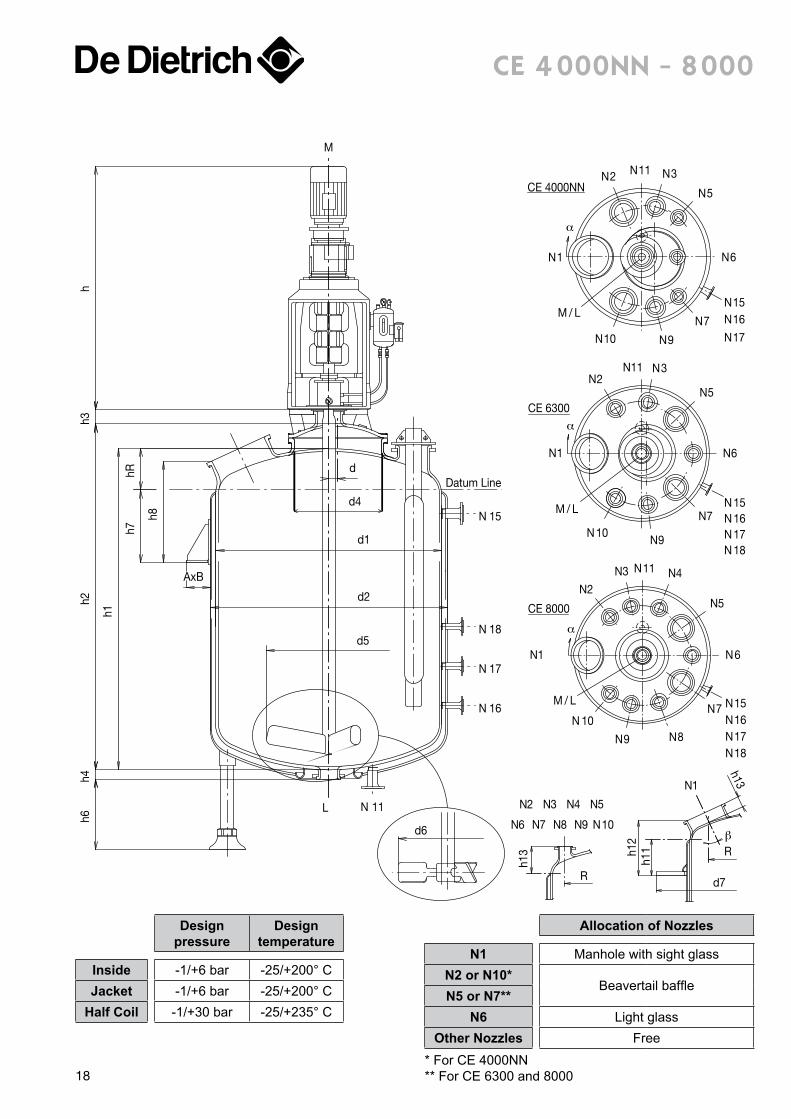
ce 4 000nn - 8 000
Designpressure
Designtemperature
Inside -1/+6 bar -25/+200° CJacket -1/+6 bar -25/+200° C
Half Coil -1/+30 bar -25/+235° C
Allocation of Nozzles
N1 Manhole with sight glassN2 or N10*
Beavertail baffleN5 or N7**
N6 Light glassOther Nozzles Free
* For CE 4000NN** For CE 6300 and 800018
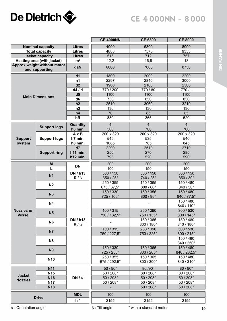
ce 4 000nn - 8 000
CE 4000NN CE 6300 CE 8000
Nominal capacity Litres 4000 6300 8000Total capacity Litres 4888 7575 9353
Jacket capacity Litres 515 712 757Heating area (with jacket) m² 12,2 16,8 18
Approx.weight without motor and supporting daN 6000 7600 8750
Main Dimensions
d1 1800 2000 2200h1 2297 2840 3000d2 1900 2100 2300
d4 / d 770 / 200 770 / 80 770 / -d5 1100 1100 1100d6 750 850 850h2 2510 3060 3210h3 130 130 130h4 70 85 85hR 330 365 520
Support system
Support legs Quantityh6 min.
4500
4700
4700
Support lugsA x B
h7 min.h8 min.
200 x 3205451085
200 x 320535785
200 x 320540845
Support ringd7
h11 min.h12 min.
2290250795
2510270520
2710285590
Nozzles on Vessel
M DN 200 200 200L 100 150 150
N1 DN / h13 R / β
500 / 150650 / 25°
500 / 150740 / 25°
500 / 150850 / 30°
N2
DN / h13 R / α
250 / 355675 / 67,5°
150 / 365800 / 60°
150 / 480840 / 50°
N3 150 / 330725 / 105°
150 / 356800 / 95°
150 / 480840 / 77,5°
N4 - - 150 / 480840 / 110°
N5 100 / 315750 / 132,5°
250 / 390750 / 135°
300 / 530800 / 145°
N6 - 150 / 365800 / 180°
150 / 480840 / 180°
N7 100 / 315750 / 227,5°
250 / 390750 / 225°
300 / 530800 / 215°
N8 - - 150 / 480840 / 250°
N9 150 / 330725 / 255°
150 / 365800 / 265°
150 / 480840 / 282,5°
N10 250 / 355675 / 292,5°
150 / 365800 / 300°
150 / 480840 / 310°
Jacket Nozzles
N11
DN / α
50 / 90° 80 /90° 80 / 90°N15 50 / 208° 80 / 208° 80 / 208°N16 50 / 208° 50 / 208° 50 / 208°N17 50 / 208° 50 / 208° 50 / 208°N18 - 50 / 208° 50 / 208°
DriveMDL 100 100 100h * 2155 2155 2155
α : Orientation angle β : Tilt angle * with a standard motor 19
Din
ra
nge
N16
N17
N18
N19
N15
Datum Line
N 11L
M
AxB
h8
h7hR
h1
h4h
d1
d2
h6
d5
h2h3
d4
N 1
N 2
N 3N 4
N 11
N 5
N 6
N15N16N17N18N19
N 7
N 8N 9N 10
M / L
h11h1
2
d7
R
R
h13
N2 N3 N4 N5
N6 N7 N8 N9 N10
N1
α
β
h13
d6
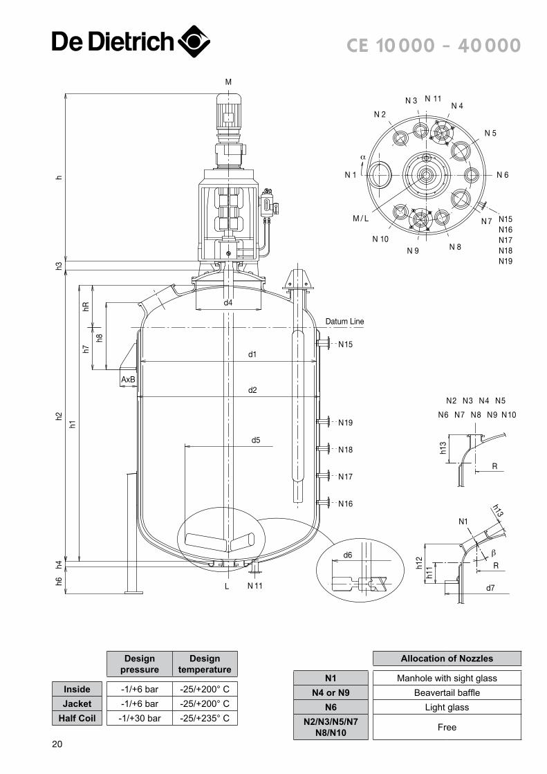
ce 10 000 - 40 000
Designpressure
Designtemperature
Inside -1/+6 bar -25/+200° CJacket -1/+6 bar -25/+200° C
Half Coil -1/+30 bar -25/+235° C
Allocation of Nozzles
N1 Manhole with sight glassN4 or N9 Beavertail baffle
N6 Light glassN2/N3/N5/N7
N8/N10 Free
20
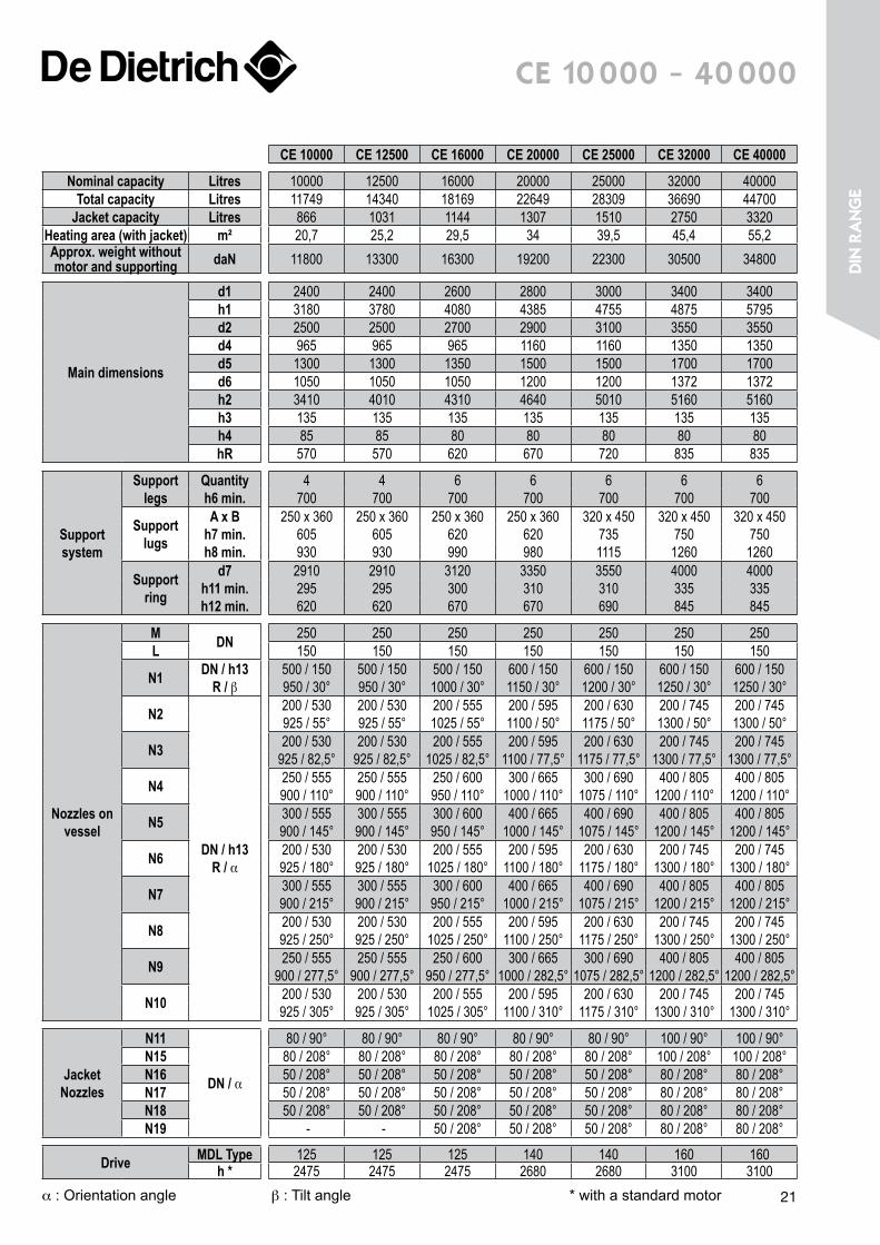
ce 10 000 - 40 000
CE 10000 CE 12500 CE 16000 CE 20000 CE 25000 CE 32000 CE 40000
Nominal capacity Litres 10000 12500 16000 20000 25000 32000 40000Total capacity Litres 11749 14340 18169 22649 28309 36690 44700
Jacket capacity Litres 866 1031 1144 1307 1510 2750 3320Heating area (with jacket) m² 20,7 25,2 29,5 34 39,5 45,4 55,2Approx. weight without motor and supporting daN 11800 13300 16300 19200 22300 30500 34800
Main dimensions
d1 2400 2400 2600 2800 3000 3400 3400h1 3180 3780 4080 4385 4755 4875 5795d2 2500 2500 2700 2900 3100 3550 3550d4 965 965 965 1160 1160 1350 1350d5 1300 1300 1350 1500 1500 1700 1700d6 1050 1050 1050 1200 1200 1372 1372h2 3410 4010 4310 4640 5010 5160 5160h3 135 135 135 135 135 135 135h4 85 85 80 80 80 80 80hR 570 570 620 670 720 835 835
Support system
Support legs
Quantityh6 min.
4700
4700
6700
6700
6700
6700
6700
Support lugs
A x Bh7 min.h8 min.
250 x 360605930
250 x 360605930
250 x 360620990
250 x 360620980
320 x 4507351115
320 x 4507501260
320 x 4507501260
Support ring
d7h11 min.h12 min.
2910295620
2910295620
3120300670
3350310670
3550310690
4000335845
4000335845
Nozzles on vessel
M DN 250 250 250 250 250 250 250L 150 150 150 150 150 150 150
N1 DN / h13 R / β
500 / 150950 / 30°
500 / 150950 / 30°
500 / 1501000 / 30°
600 / 1501150 / 30°
600 / 1501200 / 30°
600 / 1501250 / 30°
600 / 1501250 / 30°
N2
DN / h13 R / α
200 / 530925 / 55°
200 / 530925 / 55°
200 / 5551025 / 55°
200 / 5951100 / 50°
200 / 6301175 / 50°
200 / 7451300 / 50°
200 / 7451300 / 50°
N3 200 / 530925 / 82,5°
200 / 530925 / 82,5°
200 / 5551025 / 82,5°
200 / 5951100 / 77,5°
200 / 6301175 / 77,5°
200 / 7451300 / 77,5°
200 / 7451300 / 77,5°
N4 250 / 555900 / 110°
250 / 555900 / 110°
250 / 600950 / 110°
300 / 6651000 / 110°
300 / 6901075 / 110°
400 / 8051200 / 110°
400 / 8051200 / 110°
N5 300 / 555900 / 145°
300 / 555900 / 145°
300 / 600950 / 145°
400 / 6651000 / 145°
400 / 6901075 / 145°
400 / 8051200 / 145°
400 / 8051200 / 145°
N6 200 / 530925 / 180°
200 / 530925 / 180°
200 / 5551025 / 180°
200 / 5951100 / 180°
200 / 6301175 / 180°
200 / 7451300 / 180°
200 / 7451300 / 180°
N7 300 / 555900 / 215°
300 / 555900 / 215°
300 / 600950 / 215°
400 / 6651000 / 215°
400 / 6901075 / 215°
400 / 8051200 / 215°
400 / 8051200 / 215°
N8 200 / 530925 / 250°
200 / 530925 / 250°
200 / 5551025 / 250°
200 / 5951100 / 250°
200 / 6301175 / 250°
200 / 7451300 / 250°
200 / 7451300 / 250°
N9 250 / 555900 / 277,5°
250 / 555900 / 277,5°
250 / 600950 / 277,5°
300 / 6651000 / 282,5°
300 / 6901075 / 282,5°
400 / 8051200 / 282,5°
400 / 8051200 / 282,5°
N10 200 / 530925 / 305°
200 / 530925 / 305°
200 / 5551025 / 305°
200 / 5951100 / 310°
200 / 6301175 / 310°
200 / 7451300 / 310°
200 / 7451300 / 310°
Jacket Nozzles
N11
DN / α
80 / 90° 80 / 90° 80 / 90° 80 / 90° 80 / 90° 100 / 90° 100 / 90°N15 80 / 208° 80 / 208° 80 / 208° 80 / 208° 80 / 208° 100 / 208° 100 / 208°N16 50 / 208° 50 / 208° 50 / 208° 50 / 208° 50 / 208° 80 / 208° 80 / 208°N17 50 / 208° 50 / 208° 50 / 208° 50 / 208° 50 / 208° 80 / 208° 80 / 208°N18 50 / 208° 50 / 208° 50 / 208° 50 / 208° 50 / 208° 80 / 208° 80 / 208°N19 - - 50 / 208° 50 / 208° 50 / 208° 80 / 208° 80 / 208°
Drive MDL Type 125 125 125 140 140 160 160h * 2475 2475 2475 2680 2680 3100 3100
α : Orientation angle β : Tilt angle * with a standard motor 21
Din
ra
nge
R
h10
h5
h6
R
h8
h7
h2
h1
h9
R
h10h9
P
d2
h4
h3
d1
270
225
180
90
0
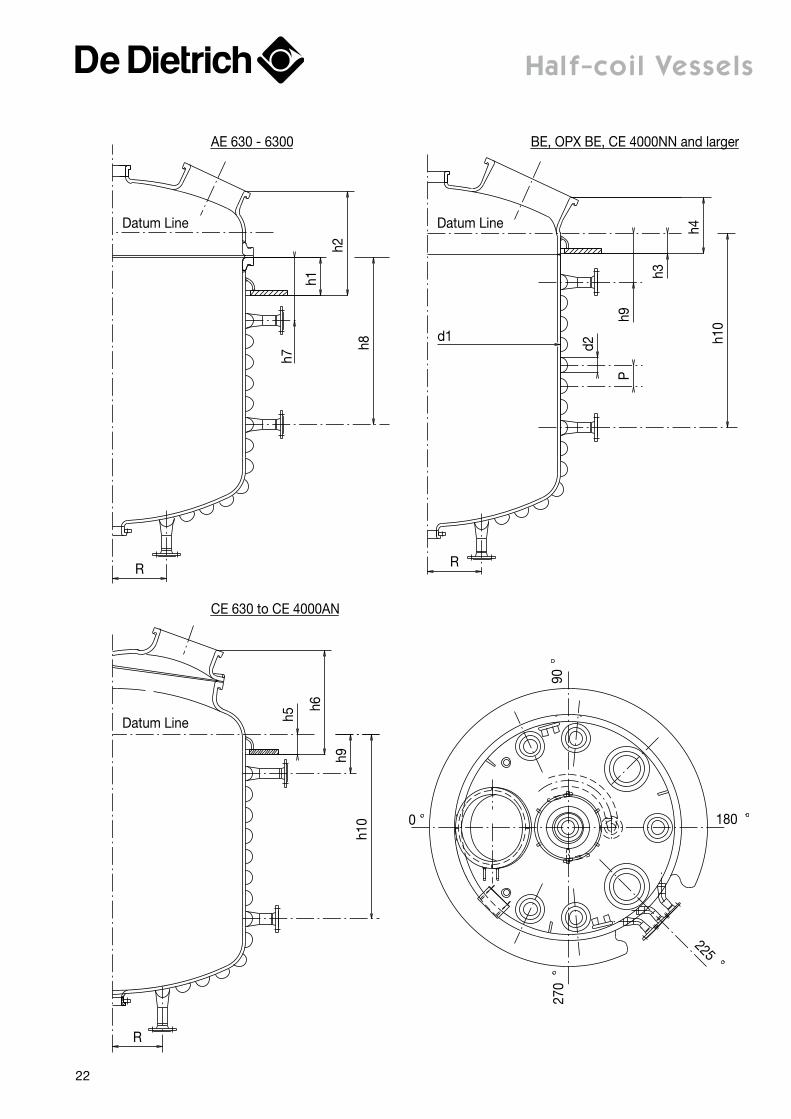
CE 630 to CE 4000AN
AE 630 - 6300
Datum Line
Datum Line
Datum Line
BE, OPX BE, CE 4000NN and larger
Half-coil Vessels
22
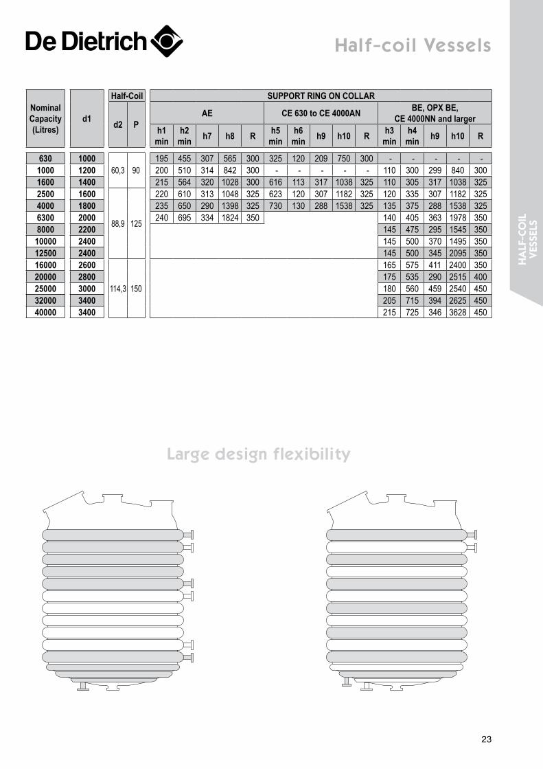
Half-coil Vessels
Large design flexibility
Nominal Capacity (Litres)
d1
Half-Coil SUPPORT RING ON COLLAR
d2 PAE CE 630 to CE 4000AN BE, OPX BE,
CE 4000NN and largerh1
minh2
min h7 h8 R h5 min
h6 min h9 h10 R h3
minh4
min h9 h10 R
630 100060,3 90
195 455 307 565 300 325 120 209 750 300 - - - - -1000 1200 200 510 314 842 300 - - - - - 110 300 299 840 3001600 1400 215 564 320 1028 300 616 113 317 1038 325 110 305 317 1038 3252500 1600
88,9 125
220 610 313 1048 325 623 120 307 1182 325 120 335 307 1182 3254000 1800 235 650 290 1398 325 730 130 288 1538 325 135 375 288 1538 3256300 2000 240 695 334 1824 350 140 405 363 1978 3508000 2200 145 475 295 1545 35010000 2400 145 500 370 1495 35012500 2400 145 500 345 2095 35016000 2600
114,3 150
165 575 411 2400 35020000 2800 175 535 290 2515 40025000 3000 180 560 459 2540 45032000 3400 205 715 394 2625 45040000 3400 215 725 346 3628 450
23
Ha
Lf-c
oiL
Ves
seLs
d5 Rh1
3
R
N 15
N 16
N 11L
h7
h8
AxB
h5h1
h2h4
h6h3
h
d2
d1
M
N5 N6N4
N2 N3
N1
N 1
N 2 N 11
N 3
N 4
N15N16
N 5
N 6
M/L
α
β
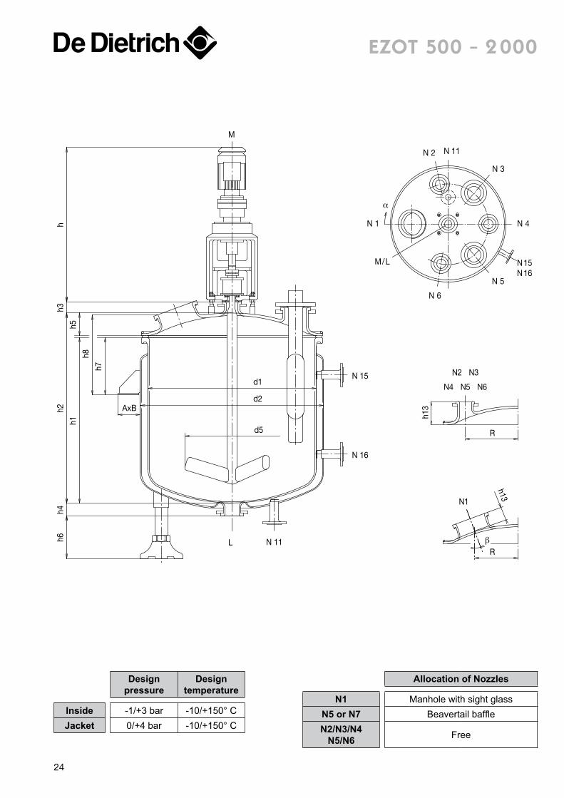
h13eZot 500 - 2 000
Designpressure
Designtemperature
Inside -1/+3 bar -10/+150° CJacket 0/+4 bar -10/+150° C
Allocation of Nozzles
N1 Manhole with sight glassN5 or N7 Beavertail baffleN2/N3/N4
N5/N6 Free
24
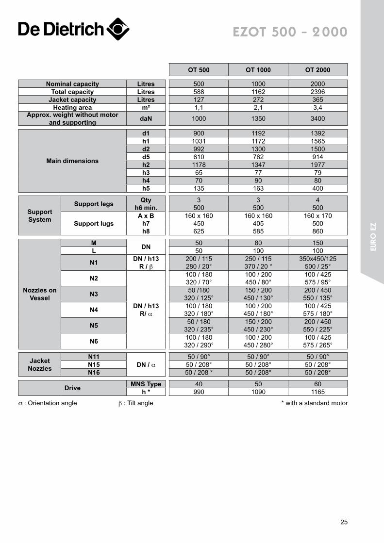
eZot 500 - 2 000
OT 500 OT 1000 OT 2000
Nominal capacity Litres 500 1000 2000Total capacity Litres 588 1162 2396
Jacket capacity Litres 127 272 365Heating area m² 1,1 2,1 3,4
Approx. weight without motor and supporting daN 1000 1350 3400
Main dimensions
d1 900 1192 1392h1 1031 1172 1565d2 992 1300 1500d5 610 762 914h2 1178 1347 1977h3 65 77 79h4 70 90 80h5 135 163 400
Support System
Support legs Qtyh6 min.
3500
3500
4500
Support lugsA x B
h7 h8
160 x 160450625
160 x 160405585
160 x 170500860
Nozzles on Vessel
M DN 50 80 150L 50 100 100
N1 DN / h13 R / β
200 / 115280 / 20°
250 / 115370 / 20 °
350x450/125500 / 25°
N2
DN / h13R/ α
100 / 180320 / 70°
100 / 200450 / 80°
100 / 425575 / 95°
N3 50 /180320 / 125°
150 / 200450 / 130°
200 / 450550 / 135°
N4 100 / 180320 / 180°
100 / 200450 / 180°
100 / 425575 / 180°
N5 50 / 180320 / 235°
150 / 200450 / 230°
200 / 450550 / 225°
N6 100 / 180320 / 290°
100 / 200450 / 280°
100 / 425575 / 265°
Jacket Nozzles
N11DN / α
50 / 90° 50 / 90° 50 / 90°N15 50 / 208° 50 / 208° 50 / 208°N16 50 / 208 ° 50 / 208° 50 / 208°
Drive MNS Type 40 50 60h * 990 1090 1165
α : Orientation angle β : Tilt angle * with a standard motor
25
euro
eZ
h1
h4h6
AxB
h7hR
Datum Line
h8
h2h3
h
d2
d1
d5
R
h13
N 15
N 17
N 16
M
N 11L
N1
N6N5 N7
N3N2 N4
N 8
N1
N 11 N2
N3
N4
N15N16N5
N6
N8
/LM
EZWB 2000
N2 N3N11
N4
N6N7
/LM
N8
N5
N15N16N17
N1
EZWB 3000 -> 6000
α
α
d4
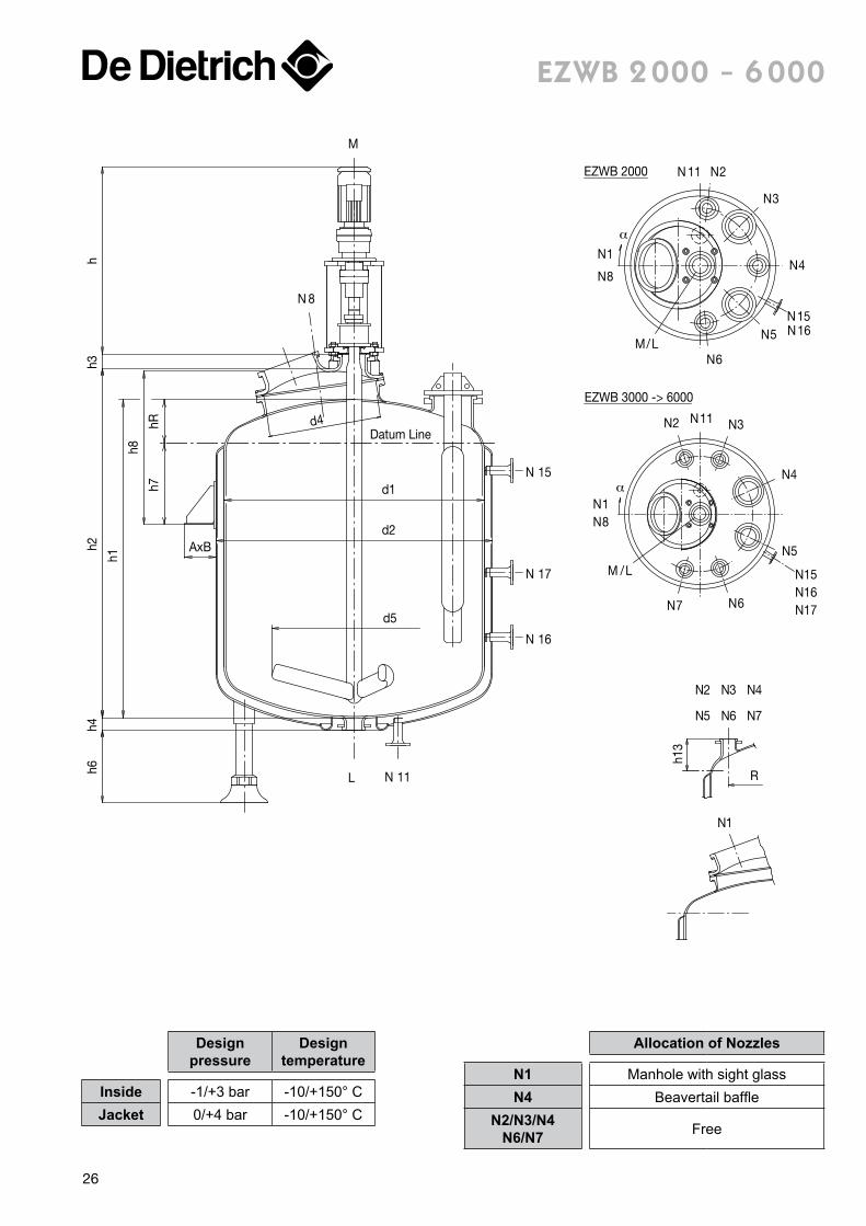
eZWB 2 000 - 6 000
Designpressure
Designtemperature
Inside -1/+3 bar -10/+150° CJacket 0/+4 bar -10/+150° C
Allocation of Nozzles
N1 Manhole with sight glassN4 Beavertail baffle
N2/N3/N4 N6/N7 Free
26
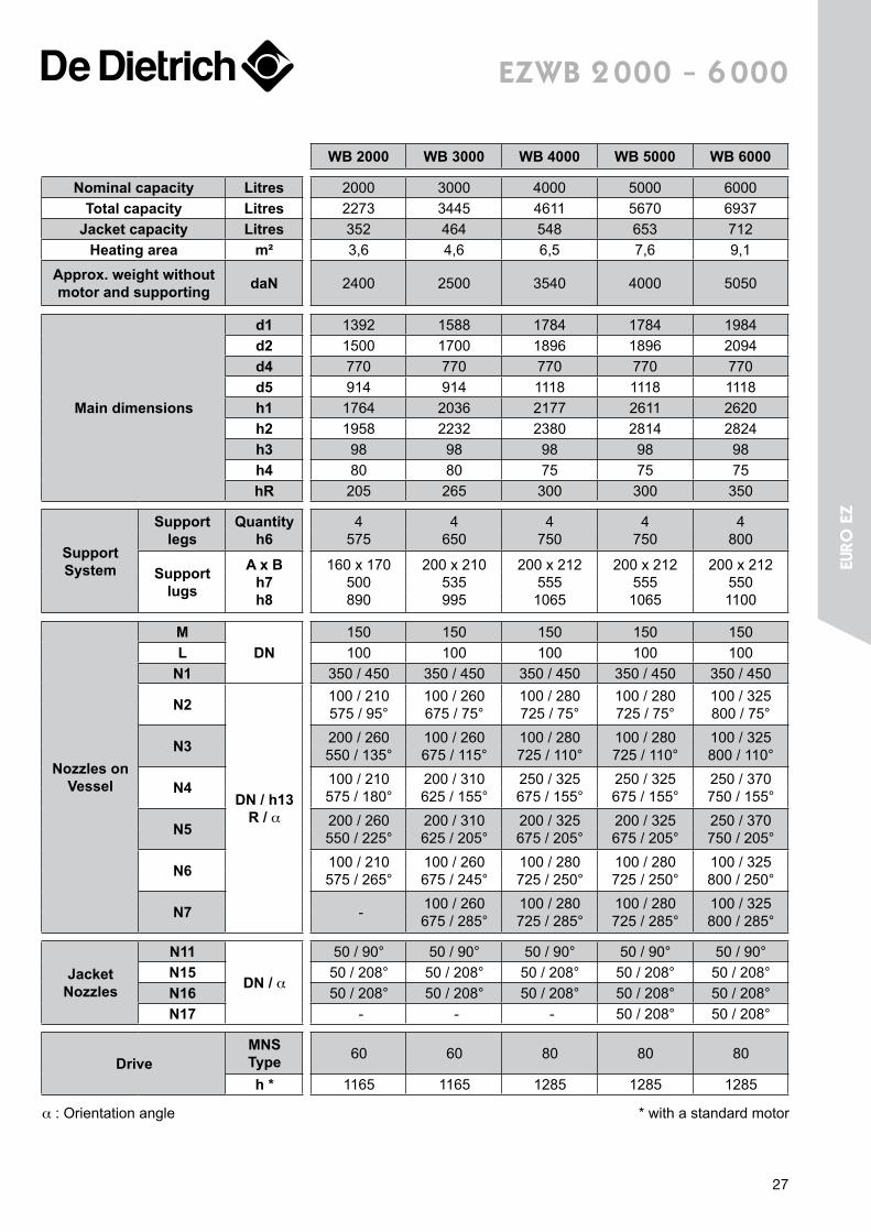
eZWB 2 000 - 6 000
WB 2000 WB 3000 WB 4000 WB 5000 WB 6000
Nominal capacity Litres 2000 3000 4000 5000 6000Total capacity Litres 2273 3445 4611 5670 6937
Jacket capacity Litres 352 464 548 653 712Heating area m² 3,6 4,6 6,5 7,6 9,1
Approx. weight without motor and supporting daN 2400 2500 3540 4000 5050
Main dimensions
d1 1392 1588 1784 1784 1984d2 1500 1700 1896 1896 2094d4 770 770 770 770 770d5 914 914 1118 1118 1118h1 1764 2036 2177 2611 2620h2 1958 2232 2380 2814 2824h3 98 98 98 98 98h4 80 80 75 75 75hR 205 265 300 300 350
Support System
Support legs
Quantityh6
4575
4650
4750
4750
4800
Support lugs
A x Bh7h8
160 x 170500890
200 x 210535995
200 x 2125551065
200 x 2125551065
200 x 2125501100
Nozzles on Vessel
MDN
150 150 150 150 150L 100 100 100 100 100
N1 350 / 450 350 / 450 350 / 450 350 / 450 350 / 450
N2
DN / h13 R / α
100 / 210575 / 95°
100 / 260675 / 75°
100 / 280725 / 75°
100 / 280725 / 75°
100 / 325800 / 75°
N3 200 / 260550 / 135°
100 / 260675 / 115°
100 / 280725 / 110°
100 / 280725 / 110°
100 / 325800 / 110°
N4 100 / 210575 / 180°
200 / 310625 / 155°
250 / 325675 / 155°
250 / 325675 / 155°
250 / 370750 / 155°
N5 200 / 260550 / 225°
200 / 310625 / 205°
200 / 325675 / 205°
200 / 325675 / 205°
250 / 370750 / 205°
N6 100 / 210575 / 265°
100 / 260675 / 245°
100 / 280725 / 250°
100 / 280725 / 250°
100 / 325800 / 250°
N7 - 100 / 260675 / 285°
100 / 280725 / 285°
100 / 280725 / 285°
100 / 325800 / 285°
Jacket Nozzles
N11
DN / α
50 / 90° 50 / 90° 50 / 90° 50 / 90° 50 / 90°N15 50 / 208° 50 / 208° 50 / 208° 50 / 208° 50 / 208°N16 50 / 208° 50 / 208° 50 / 208° 50 / 208° 50 / 208°N17 - - - 50 / 208° 50 / 208°
DriveMNS Type 60 60 80 80 80
h * 1165 1165 1285 1285 1285
α : Orientation angle * with a standard motor
27
euro
eZ
15
16d4
d1 N
Nf
N 11L
d2
h4h2
h
M
N 12N 11
R
Temperature Padfor PHARMA 160and larger sizes
h1
h11
h7
h6
N1
N2
N 3
N4
N5
N6
N 15
M/L
N 11
N 8
N 16
N 11
HALF-COIL TYPE
N 12
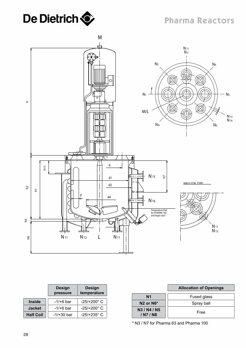
pharma reactors
Designpressure
Designtemperature
Inside -1/+6 bar -25/+200° CJacket -1/+6 bar -25/+200° C
Half Coil -1/+30 bar -25/+235° C
Allocation of Openings
N1 Fused glassN2 or N6* Spray ball
N3 / N4 / N5 / N7 / N8 Free
* N3 / N7 for Pharma 63 and Pharma 100
28
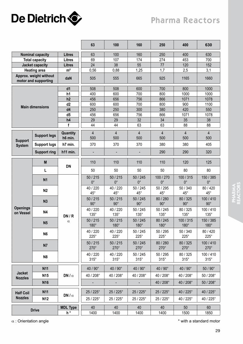
pharma reactors
63 100 160 250 400 630
Nominal capacity Litres 63 100 160 250 400 630Total capacity Litres 69 107 174 274 453 700
Jacket capacity Litres 24 38 55 77 120 152Heating area m² 0,56 0,88 1,25 1,7 2,5 3,1
Approx. weight without motor and supporting daN 505 555 665 925 1165 1660
Main dimensions
d1 508 508 600 700 800 1000h1 400 600 700 800 1000 1000h2 456 656 756 866 1071 1078d2 600 600 700 800 900 1100d4 250 250 300 380 420 550d5 456 656 756 866 1071 1078h4 29 29 32 34 35 38f 44 44 63 63 88 88
Support System
Support legs Quantityh6 min.
4500
4500
4500
4500
4500
4500
Support lugs h7 min. 370 370 370 380 380 405
Support ring h11 min. - - - 290 290 320
Openings on Vessel
MDN
110 110 110 110 120 125
L 50 50 50 50 80 80
N1
DN / R α
50 / 215 0°
50 / 215 0°
50 / 245 0°
100 / 270 0°
100 / 315 0°
150 / 385 0°
N2 40 / 22045°
40 / 22045°
50 / 245 45°
50 / 29545°
50 / 34045°
80 / 42045°
N3 50 / 21590°
50 / 21590°
50 / 24590°
80 / 28090°
80 / 32590°
100 / 41090°
N4 40 / 220135°
40 / 220135°
50 / 245135°
50 / 245135°
80 / 325135°
100 / 410135°
N5 50 / 215180°
50 / 215180°
50 / 245180°
80 / 245180°
100 / 315180°
150 / 385180°
N6 40 / 220225°
40 / 220225°
50 / 245225°
50 / 295 225°
50 / 340 225°
80 / 420 225°
N7 50 / 215 270°
50 / 215 270°
50 / 245 270°
80 / 280 270°
80 / 325 270°
100 / 410 270°
N8 40 / 220 315°
40 / 220 315°
50 / 245 315°
50 / 295 315°
80 / 325 315°
100 / 410 315°
Jacket Nozzles
N11DN / α
40 / 90° 40 / 90° 40 / 90° 40 / 90° 40 / 90° 50 / 90°
N15 40 / 208° 40 / 208° 40 / 208° 40 / 208° 40 / 208° 50 / 208°
N16 - - - 40 / 208° 40 / 208° 50 / 208°
Half Coil Nozzles
N11DN / α
25 / 225° 25 / 225° 25 / 225° 25 / 225° 40 / 225° 40 / 225°
N12 25 / 225° 25 / 225° 25 / 225° 25 / 225° 40 / 225° 40 / 225°
Drive MDL Type 40 40 40 40 50 60h * 1400 1400 1400 1400 1500 1850
α : Orientation angle * with a standard motor
29
pHa
rma
re
acto
rs
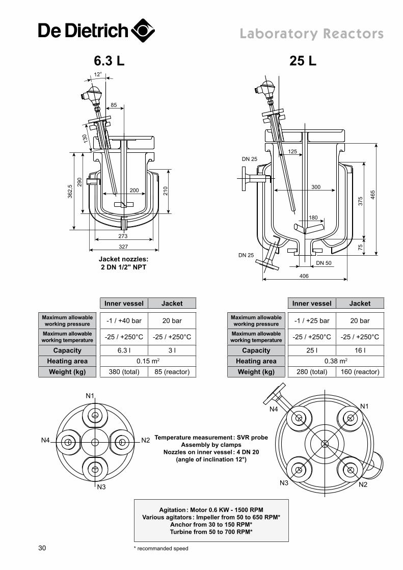
Laboratory reactors
362,
5
85
12°
6.3 L29
0
327
Jacket nozzles:2 DN 1/2" NPT
273
200
210
130
25 L
300
DN 25
DN 25
180
125
406
DN 50
7537
5 465
N1
N2
N3
N4
N1
N2N3
N4
Inner vessel Jacket
Maximum allowable working pressure -1 / +40 bar 20 bar
Maximum allowable working temperature -25 / +250°C -25 / +250°C
Capacity 6.3 l 3 lHeating area 0.15 m2
Weight (kg) 380 (total) 85 (reactor)
Inner vessel Jacket
Maximum allowable working pressure -1 / +25 bar 20 bar
Maximum allowable working temperature -25 / +250°C -25 / +250°C
Capacity 25 l 16 lHeating area 0.38 m2
Weight (kg) 280 (total) 160 (reactor)
Temperature measurement : SVR probeAssembly by clamps
Nozzles on inner vessel : 4 DN 20(angle of inclination 12°)
Agitation : Motor 0.6 KW - 1500 RPMVarious agitators : Impeller from 50 to 650 RPM*
Anchor from 30 to 150 RPM*Turbine from 50 to 700 RPM*
* recommanded speed30
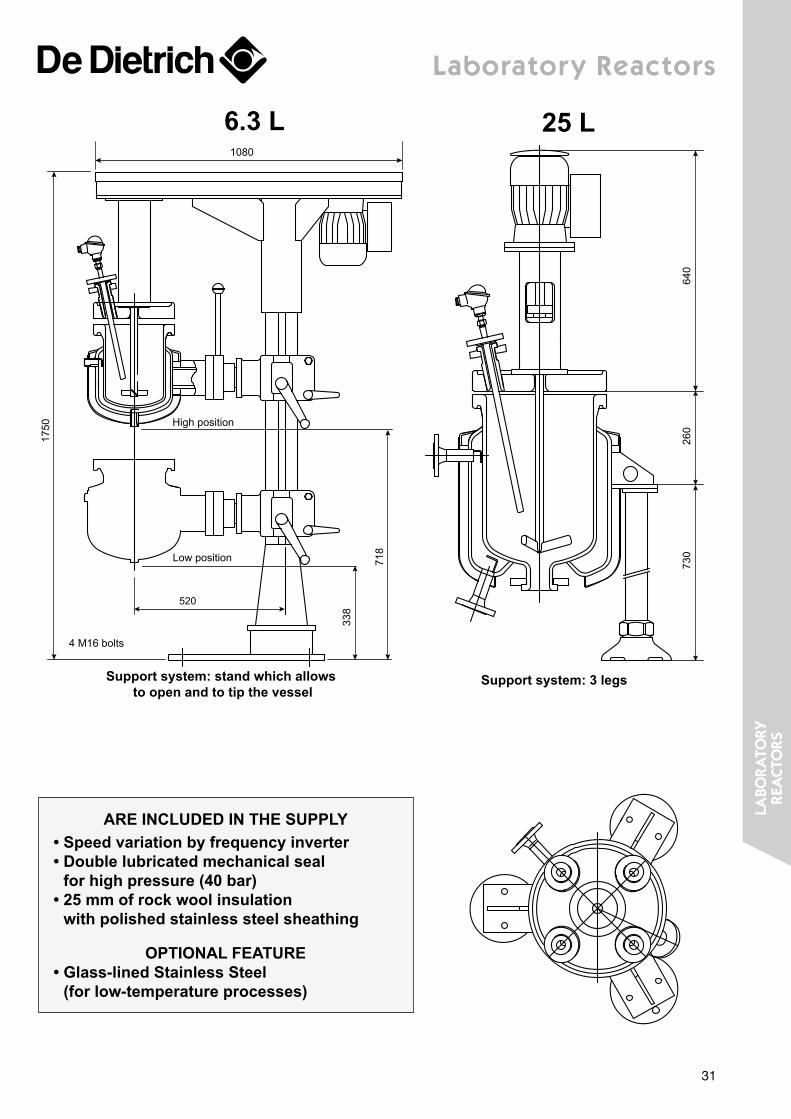
Laboratory reactors
6.3 L1080
1750
718
338
High position
Low position
4 M16 bolts
520
Support system: stand which allows to open and to tip the vessel
25 L
640
260
730
Support system: 3 legs
ARE INCLUDED IN THE SUPPLY• Speed variation by frequency inverter• Double lubricated mechanical seal
for high pressure (40 bar)• 25 mm of rock wool insulation
with polished stainless steel sheathing
OPTIONAL FEATURE• Glass-lined Stainless Steel
(for low-temperature processes)
31
LaBo
rato
ry
reacto
rs
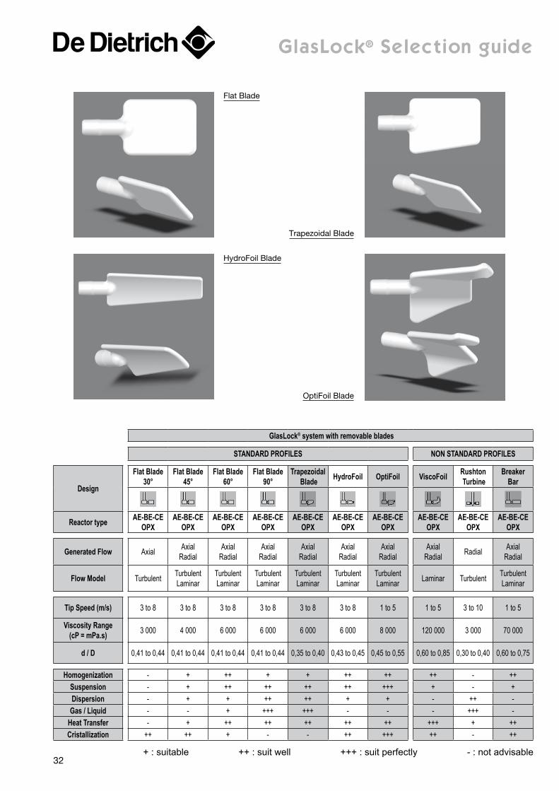
glasLock® selection guide
Flat Blade
Trapezoidal Blade
HydroFoil Blade
OptiFoil Blade
GlasLock® system with removable blades
STANDARD PROFILES NON STANDARD PROFILES
Design
Flat Blade30°
Flat Blade45°
Flat Blade60°
Flat Blade90°
Trapezoidal Blade HydroFoil OptiFoil ViscoFoil Rushton
TurbineBreaker
Bar
Reactor type AE-BE-CE OPX
AE-BE-CE OPX
AE-BE-CE OPX
AE-BE-CE OPX
AE-BE-CE OPX
AE-BE-CE OPX
AE-BE-CE OPX
AE-BE-CE OPX
AE-BE-CE OPX
AE-BE-CE OPX
Generated Flow Axial Axial Radial
Axial Radial
Axial Radial
Axial Radial
Axial Radial
Axial Radial
Axial Radial Radial Axial
Radial
Flow Model Turbulent Turbulent Laminar
Turbulent Laminar
Turbulent Laminar
Turbulent Laminar
Turbulent Laminar
Turbulent Laminar Laminar Turbulent Turbulent
Laminar
Tip Speed (m/s) 3 to 8 3 to 8 3 to 8 3 to 8 3 to 8 3 to 8 1 to 5 1 to 5 3 to 10 1 to 5
Viscosity Range(cP = mPa.s) 3 000 4 000 6 000 6 000 6 000 6 000 8 000 120 000 3 000 70 000
d / D 0,41 to 0,44 0,41 to 0,44 0,41 to 0,44 0,41 to 0,44 0,35 to 0,40 0,43 to 0,45 0,45 to 0,55 0,60 to 0,85 0,30 to 0,40 0,60 to 0,75
Homogenization - + ++ + + ++ ++ ++ - ++Suspension - + ++ ++ ++ ++ +++ + - +Dispersion - + + ++ ++ + + - ++ -Gas / Liquid - - + +++ +++ - - - +++ -
Heat Transfer - + ++ ++ ++ ++ ++ +++ + ++Cristallization ++ ++ + - - ++ +++ ++ - ++
+ : suitable ++ : suit well +++ : suit perfectly - : not advisable 32
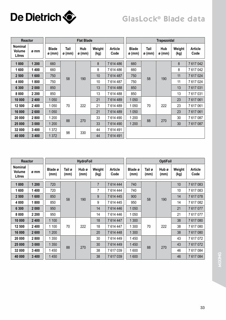
glasLock® Blade data
Reactor Flat Blade TrapezoidalNominal Volume Litres
ø mm Blade ø (mm)
Tail ø (mm)
Hub ø (mm)
Weight (kg)
Article Code
Blade ø (mm)
Tail ø (mm)
Hub ø (mm)
Weight (kg)
Article Code
1 000 1 200 660
58 190
8 7 614 486 660
58 190
8 7 617 0421 600 1 400 660 8 7 614 486 660 8 7 617 0422 500 1 600 750 10 7 614 487 750 11 7 617 0244 000 1 800 750 10 7 614 487 750 11 7 617 0246 300 2 000 850 13 7 614 488 850 13 7 617 0318 000 2 200 850 13 7 614 488 850 13 7 617 03110 000 2 400 1 050
70 22221 7 614 489 1 050
70 22223 7 617 061
12 500 2 400 1 050 21 7 614 489 1 050 23 7 617 06116 000 2 600 1 050 21 7 614 489 1 050 23 7 617 06120 000 2 800 1 200
88 27033 7 614 490 1 200
88 27030 7 617 087
25 000 3 000 1 200 33 7 614 490 1 200 30 7 617 08732 000 3 400 1 372
98 33044 7 614 491
40 000 3 400 1 372 44 7 614 491
Reactor HydroFoil OptiFoilNominal Volume Litres
ø mm Blade ø (mm)
Tail ø (mm)
Hub ø (mm)
Weight (kg)
Article Code
Blade ø (mm)
Tail ø (mm)
Hub ø (mm)
Weight (kg)
Article Code
1 000 1 200 720
58 190
7 7 614 444 740
58 190
10 7 617 0831 600 1 400 720 7 7 614 444 740 10 7 617 0832 500 1 600 850 9 7 614 445 900 14 7 617 0784 000 1 800 850 9 7 614 445 950 14 7 617 0826 300 2 000 950 14 7 614 446 1 050 21 7 617 0778 000 2 200 950 14 7 614 446 1 050 21 7 617 07710 000 2 400 1 100
70 22218 7 614 447 1 300
70 22238 7 617 080
12 500 2 400 1 100 18 7 614 447 1 300 38 7 617 08016 000 2 600 1 200 20 7 614 448 1 300 38 7 617 08020 000 2 800 1 350
88 270
30 7 614 449 1 450
88 270
43 7 617 07225 000 3 000 1 350 30 7 614 449 1 450 43 7 617 07232 000 3 400 1 450 38 7 617 039 1 600 46 7 617 08440 000 3 400 1 450 38 7 617 039 1 600 46 7 617 084
33
miX
ing
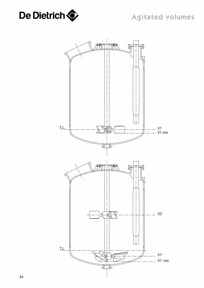
T.L.
T.L.
V1V1 min
V2'
V1'
V1' min
agitated volumes
34
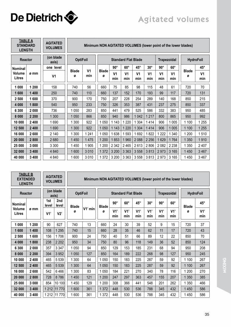
agitated volumes
TABLE A STANDARD
LENGTH
AGITATED VOLUMES Minimum NON AGITATED VOLUMES (lower point of the lower blades)
Reactor (on blade axis) OptiFoil Standard Flat Blade Trapezoidal HydroFoil
Nominal Volume Litres
ø mmone level
Blade ø
V1 min
Blade ø
90° 60° 45° 30° 90° 60°Blade
ø
45°
V1 V1 min
V1min
V1min
V1min
V1min
V1min
V1 min
1 000 1 200 158 740 56 660 75 85 98 115 48 61 720 701 600 1 400 250 740 110 660 137 152 170 193 99 117 720 1312 500 1 600 370 900 170 750 207 228 254 289 140 168 850 2154 000 1 800 540 950 233 750 326 353 387 431 237 275 850 3376 300 2 000 736 1 050 283 850 441 479 525 586 332 383 950 4858 000 2 200 1 300 1 050 866 850 940 986 1 042 1 217 800 865 950 99210 000 2 400 1 690 1 300 922 1 050 1 143 1 220 1 304 1 414 906 1 005 1 100 1 25512 500 2 400 1 690 1 300 922 1 050 1 143 1 220 1 304 1 414 906 1 005 1 100 1 25516 000 2 600 2 140 1 300 1 241 1 050 1 638 1 593 1 692 1 822 1 222 1 340 1 200 1 51020 000 2 800 2 680 1 450 1 475 1 200 1 853 1 960 2 088 2 256 1 629 1 764 1 350 1 91025 000 3 000 3 300 1 450 1 905 1 200 2 342 2 465 2 613 2 806 2 082 2 238 1 350 2 40732 000 3 400 4 840 1 600 3 010 1 372 3 200 3 363 3 558 3 813 2 973 3 165 1 450 3 46740 000 3 400 4 840 1 600 3 010 1 372 3 200 3 363 3 558 3 813 2 973 3 165 1 450 3 467
TABLE B EXTENDED
LENGTH
AGITATED VOLUMES Minimum NON AGITATED VOLUMES (lower point of the lower blades)
Reactor (on blade axis) OptiFoil Standard Flat Blade Trapezoidal HydroFoil
Nominal Volume Litres
ø mm
1st level
2nd level Blade
ø V1’ min Blade ø
90° 60° 45° 30° 90° 60°Blade
ø
45°
V1’ V2’ V1’ min
V1’ min
V1’ min
V1’ min
V1’ min
V1’ min
V1’ min
1 000 1 200 90 627 740 13 660 24 30 39 52 9 15 720 371 600 1 400 108 1 295 740 15 660 28 35 46 62 11 17 720 432 500 1 600 156 1 706 900 24 750 40 51 66 89 12 22 850 704 000 1 800 238 2 202 950 34 750 80 96 118 149 36 52 850 1246 300 2 000 357 3 347 1 050 94 850 129 153 185 231 68 94 950 2088 000 2 200 394 3 952 1 050 127 850 164 189 222 268 98 127 950 24510 000 2 400 465 5 539 1 300 64 1 050 150 183 225 287 59 92 1 100 26712 500 2 400 465 5 539 1 300 64 1 050 150 183 225 287 59 92 1 100 26716 000 2 600 542 6 466 1 300 83 1 050 184 221 270 340 78 116 1 200 27020 000 2 800 728 8 786 1 450 121 1 200 247 297 363 457 155 207 1 350 38525 000 3 000 854 10 100 1 450 129 1 200 308 366 441 548 201 262 1 350 46632 000 3 400 1 212 11 770 1 600 361 1 372 448 530 536 788 345 432 1 450 58640 000 3 400 1 212 11 770 1 600 361 1 372 448 530 536 788 345 432 1 450 586
35
miX
ing
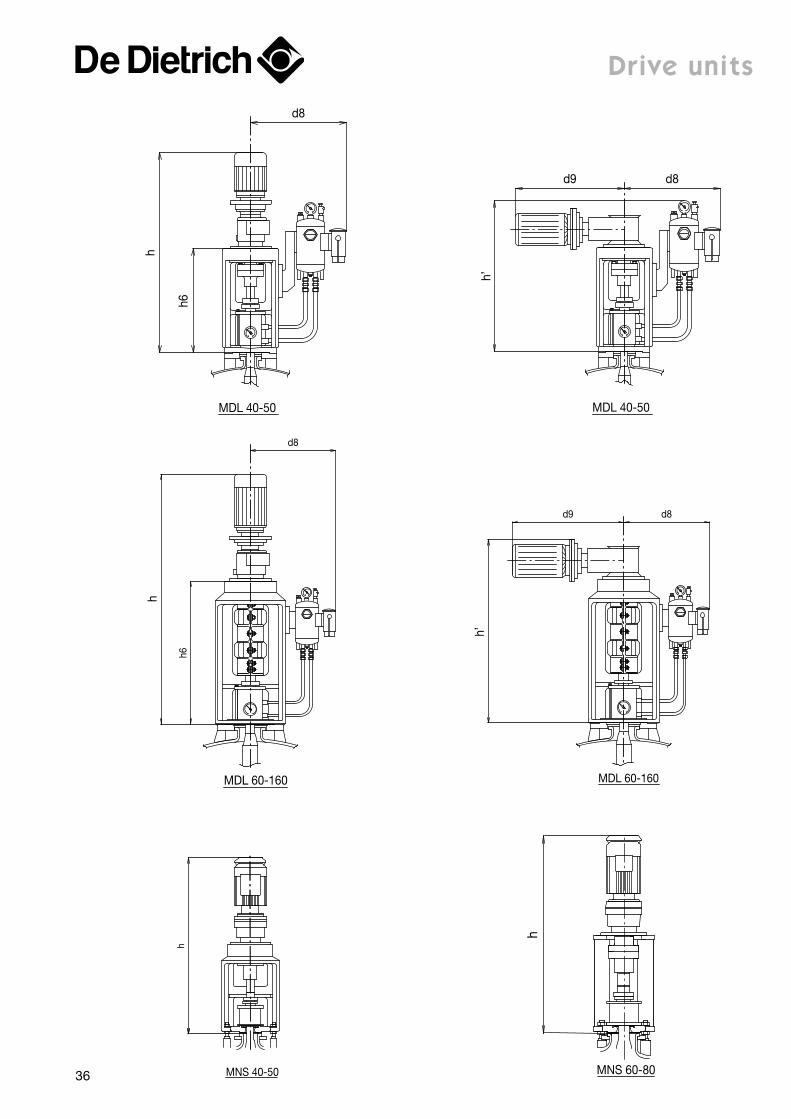
d8
h
d8
h
d8
h’
d9
MDL 40-50
MDL 60-160 MDL 60-160
d8
MDL 40-50
d9h6
h6
h’
h
h
MNS 60-80
MNS 40-50
Drive units
36
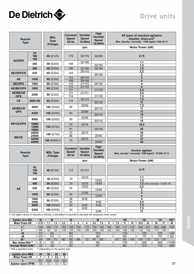
Drive units
Reactor Type
MDL Type
(Flange)
Constant Speed 50 Hz
Variable Speed
10-50Hz
High Variable Speed
10-60Hz
All types of standard agitators Impeller, GlasLock®
Max. density / viscosity : 1300 kg/m3 / 500 cP (*)
rpm Motor Power (kW)
AE/OPX
63100160
40 (E125) 176 32/176 32/200 0,75
250 50 (E200) 166 32/166 1,132/184 1,5
400 50 (E200) 166 32/166 32/184 1,5AE/OPX/CE 630 60 (E250) 143 29/143 2,2
29/166 3AE 1000 60 (E250) 143 29/143 3
169 29/169 4BE/OPX 1000 80 (E300) 110 21/110 29/150 4
AE/BE/OPX 1600 80 (E300) 110 21/110 4111 21/125 5,5
AE/BE/CE OPX 2500 80 (E300) 111 21/111 5,5
114 21/125 7,5CE 4000 AN 80 (E300) 114 30/114 7,5
30/120 11
AE/BE/CE OPX
4000 100 (E400) 99 20/99 7,520/115 11
6300 100 (E500) 99 20/99 1120/115 15
BE/CE/OPX8000 100 (E500) 99 20/99 11
20/110 1510000 12500 16000
125 (E700)79 25/79 18,591 25/100 22
BE/CE20000 25000 140 (E700) 73 20/73 30
86 20/90 3732000 40000 160 (E900/1) 73 20/73 37
20/90 45
Reactor Type
MDL Type (Flange)
Constant Speed 50 Hz
Variable Speed
10-50Hz
High Variable Speed
10-60Hz
Anchor agitatorMax. density / viscosity: 1300 kg/m3 / 15 000 cP (*)
rpm Motor Power (kW)
AE
63 100160
40 (E125) 112 21/112 0,75
250 50 (E200) 79 15/79 1,115/93 1,5
400 50 (E200) 79 15/79 15/93 1,5 (max viscosity = 8 000 cP)
630 60 (E250) 55 12/55 2,212/65 3
1000 60 (E250) 55 12/55 312/65 4
1600 2500 80 (E300) 38 8/38 4
40 8/45 5,54000 100 (E400) 30 6/30 6/36 7,56300 100 (E500) 30 6/30 7,5
6/36 11(*) for higher values of viscosity or density, a simulation is required to calculate the necessary motor power
Agitator drive MDL 40 50 60 80 100 125 140 160**Motor Power kW 0,75 1,1 1,5 2,2 3 4 4 5,5 7,5 11 7,5 11 15 18,5 22 30 37 45
h * 1040 1090 1115 1505 1505 1505 1725 1790 1825 1940 1995 2110 2155 2440 2475 2565 2680 3100h’ * 695 720 720 1105 1105 1105 1285 1305 1305 1335 1455 1480 1480 1720 1720 1770 1795 -h6 510 535 865 1015 1150 1350 1350 1400d8 470 515 510 580 690 770 770 600
d9 * 538 548 573 682 682 688 722 787 825 - 872 985 1030 1097 1135 1233 1347 -Max. torque (Nm) ** 50 150 320 800 1750 3200 5800 11800
Average Weight (daN) * 122 183 291 577 963 1519 1722 2600* With a standard motor ** Depending on the reactor size
Agitator drive MNS 40 50 60 80Motor Power kW 1 2 3,6 5
h 931 1039 1127 1247Agitator speed (RPM) 125 121 112 92 37
miX
ing

equipmentClamped top Receivers RS / RD ________________________ 40
Closed Receivers RFS / RFD ____________________________ 41
Storage Tanks ______________________________________ 42-43
Columns _______________________________________________ 44
Conical Dryers SR _____________________________________ 45
Condensers EC ________________________________________ 46
Heat Exchangers ED ___________________________________ 47
Shell and Tube Heat Exchangers __________________ 48-49
Pipes & Fittings ____________________________________ 50-52
Loose Flanges _________________________________________ 53
Gaskets _______________________________________________ 54
Clamps ________________________________________________ 55
Baffles _________________________________________________ 56
Dip Pipes ______________________________________________ 57
CleanValves ________________________________________ 58-59
equi
pmen
t
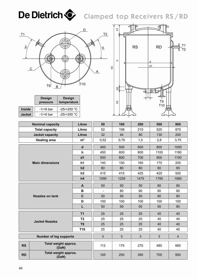
clamped top receivers rs / rD
T1
30°
DT2
C
T9 BT10
A
30° RDRS
h1h2
h
h4
h3
T1T2
T9T10
d
L
d1
Nominal capacity Litres 50 100 200 500 800Total capacity Litres 52 108 210 525 875
Jacket capacity Litres 32 44 80 130 200Heating area m2 0,52 0,76 1,5 2,8 3,75
Main dimensions
d 400 500 600 800 1000h 450 600 800 1100 1180
d1 500 600 700 900 1100h1 140 150 160 170 205h2 80 80 80 80 85h3 415 415 425 425 500h4 1090 1255 1475 1785 1980
Nozzles on tank
A 50 50 50 80 80B - 80 80 80 80C 50 50 50 80 80D 100 100 100 100 100L 50 50 50 50 80
Jacket Nozzles
T1 25 25 25 40 40T2 25 25 25 40 40T9 25 25 25 40 40
T10 25 25 25 40 40
Number of leg supports 3 3 3 3 4
RS Total weight approx. (DaN) 112 175 270 480 660
RD Total weight approx. (DaN) 165 250 390 700 950
Design pressure
Design temperature
Inside -1/+6 bar -25/+200 °CJacket -1/+6 bar -25/+200 °C
40
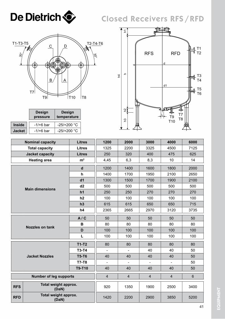
closed receivers rfs / rfD
RFDRFS
h1h2
h
h4
h3
T1T2
T9T10
d
d1
T3T4
T5T6
T7T8
L
30°30°
D
T7T9 T10 T8
T2-T4-T6T1-T3-T5
B
C
A
Nominal capacity Litres 1200 2000 3000 4000 6000Total capacity Litres 1325 2200 3325 4500 7125
Jacket capacity Litres 250 320 400 475 625Heating area m2 4,45 6,3 8,3 10 14
Main dimensions
d 1200 1400 1600 1800 2000h 1400 1700 1950 2100 2650
d1 1300 1500 1700 1900 2100d2 500 500 500 500 500h1 250 250 270 270 270h2 100 100 100 100 100h3 615 615 650 650 715h4 2365 2665 2970 3120 3735
Nozzles on tank
A / C 50 50 50 50 50B 80 80 80 80 80D 100 100 100 100 100L 100 100 100 100 100
Jacket Nozzles
T1-T2 80 80 80 80 80T3-T4 - - 40 40 50T5-T6 40 40 40 40 50T7-T8 - - - - 50
T9-T10 40 40 40 40 50
Number of leg supports 4 4 4 4 6
RFS Total weight approx. (DaN) 920 1350 1900 2500 3400
RFD Total weight approx. (DaN) 1420 2200 2900 3850 5200
Design pressure
Design temperature
Inside -1/+6 bar -25/+200 °CJacket -1/+6 bar -25/+200 °C
41 equi
pmen
t
storage tanks
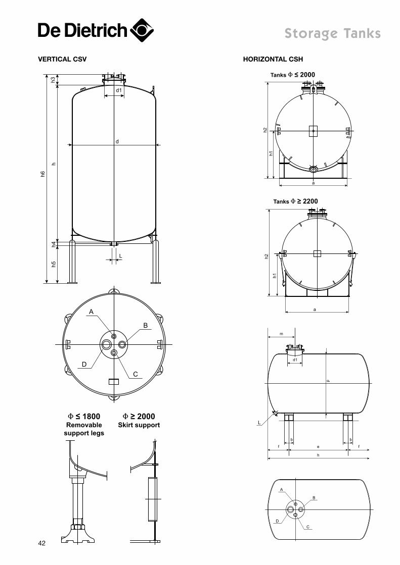
d
h3h4
h
h6
h5
d1
L
B
D
C
A
d1
b
f e
h
f
b
m
d
L
B
D
C
A
Φ ≤ 1800Removable
support legs
Φ ≥ 2000Skirt support
a
h1h2
Tanks Φ ≤ 2000
a
h1
h2
Tanks Φ ≥ 2200
Vertical cSV horizontal cSh
42
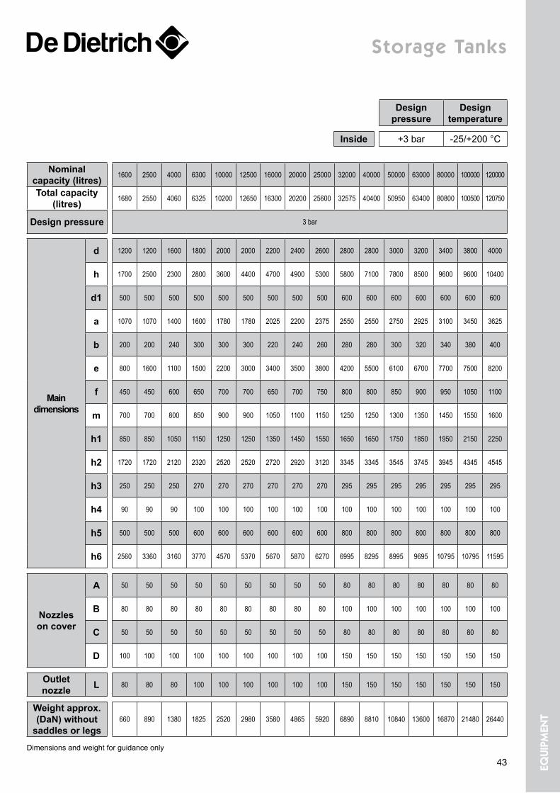
storage tanks
Nominal capacity (litres) 1600 2500 4000 6300 10000 12500 16000 20000 25000 32000 40000 50000 63000 80000 100000 120000
Total capacity (litres) 1680 2550 4060 6325 10200 12650 16300 20200 25600 32575 40400 50950 63400 80800 100500 120750
Design pressure 3 bar
Main dimensions
d 1200 1200 1600 1800 2000 2000 2200 2400 2600 2800 2800 3000 3200 3400 3800 4000
h 1700 2500 2300 2800 3600 4400 4700 4900 5300 5800 7100 7800 8500 9600 9600 10400
d1 500 500 500 500 500 500 500 500 500 600 600 600 600 600 600 600
a 1070 1070 1400 1600 1780 1780 2025 2200 2375 2550 2550 2750 2925 3100 3450 3625
b 200 200 240 300 300 300 220 240 260 280 280 300 320 340 380 400
e 800 1600 1100 1500 2200 3000 3400 3500 3800 4200 5500 6100 6700 7700 7500 8200
f 450 450 600 650 700 700 650 700 750 800 800 850 900 950 1050 1100
m 700 700 800 850 900 900 1050 1100 1150 1250 1250 1300 1350 1450 1550 1600
h1 850 850 1050 1150 1250 1250 1350 1450 1550 1650 1650 1750 1850 1950 2150 2250
h2 1720 1720 2120 2320 2520 2520 2720 2920 3120 3345 3345 3545 3745 3945 4345 4545
h3 250 250 250 270 270 270 270 270 270 295 295 295 295 295 295 295
h4 90 90 90 100 100 100 100 100 100 100 100 100 100 100 100 100
h5 500 500 500 600 600 600 600 600 600 800 800 800 800 800 800 800
h6 2560 3360 3160 3770 4570 5370 5670 5870 6270 6995 8295 8995 9695 10795 10795 11595
Nozzles on cover
A 50 50 50 50 50 50 50 50 50 80 80 80 80 80 80 80
B 80 80 80 80 80 80 80 80 80 100 100 100 100 100 100 100
C 50 50 50 50 50 50 50 50 50 80 80 80 80 80 80 80
D 100 100 100 100 100 100 100 100 100 150 150 150 150 150 150 150
Outlet nozzle L 80 80 80 100 100 100 100 100 100 150 150 150 150 150 150 150
Weight approx. (DaN) without
saddles or legs660 890 1380 1825 2520 2980 3580 4865 5920 6890 8810 10840 13600 16870 21480 26440
Dimensions and weight for guidance only
Design pressure
Design temperature
Inside +3 bar -25/+200 °C
43 equi
pmen
t
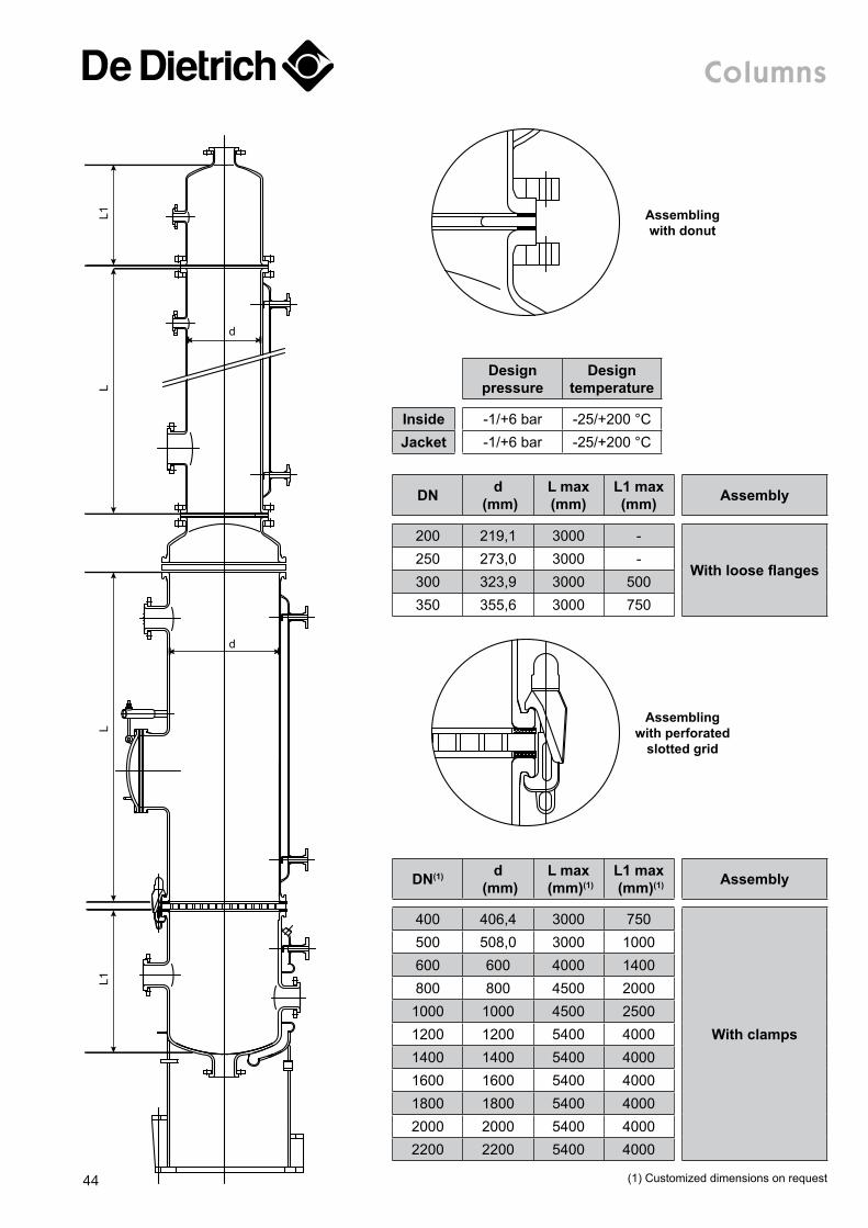
columns
DN d (mm)
L max (mm)
L1 max (mm) Assembly
200 219,1 3000 -
With loose flanges250 273,0 3000 -300 323,9 3000 500350 355,6 3000 750
L1
d
d
L1L
L
Design pressure
Design temperature
Inside -1/+6 bar -25/+200 °CJacket -1/+6 bar -25/+200 °C
Assembling with donut
Assembling with perforated
slotted grid
DN(1) d (mm)
L max (mm)(1)
L1 max (mm)(1) Assembly
400 406,4 3000 750
With clamps
500 508,0 3000 1000600 600 4000 1400800 800 4500 20001000 1000 4500 25001200 1200 5400 40001400 1400 5400 40001600 1600 5400 40001800 1800 5400 40002000 2000 5400 40002200 2200 5400 4000
(1) Customized dimensions on request44
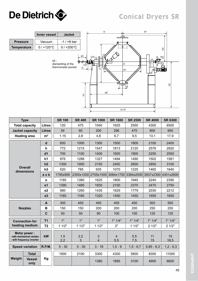
conical Dryers sr
e
e3
e1
a x b
e2
d
A
d1
h3
T2
T21/2"
1/2"
h1
h
h2B
C
Type SR 100 SR 400 SR 1000 SR 1600 SR 2500 SR 4000 SR 6300Total capacity Litres 120 475 1040 1625 2550 4300 6500
Jacket capacity Litres 54 60 200 296 475 800 950Heating area m2 1,15 2,8 4,8 6,7 9,5 13,1 17,9
Overall dimensions
d 600 1000 1300 1500 1800 2100 2400h 772 1215 1547 1813 2120 2576 2920d1 700 1100 1400 1600 1900 2250 2550h1 876 1288 1327 1494 1490 1502 1581h2 1300 1950 2150 2450 2600 2850 3100h3 520 785 935 1070 1225 1465 1640
a x b 1795x900 2355x1200 2705x1500 3084x1700 3384x2000 3937x2300 4301x2600e 1185 1380 1625 1800 1945 2240 2390e1 1390 1485 1830 2100 2370 2470 2750e2 980 1260 1435 1629 1779 2030 2212e3 1160 1160 1320 1450 1450 1650 1650
NozzlesA 300 450 450 450 450 500 500B 150 150 200 200 200 250 250C 50 50 80 100 100 125 125
Connection for heating medium
T1 1" 1" 1" 1" 1/4" 1" 1/4" 1" 1/4" 1" 1/4"T2 1 1/2" 1 1/2" 1 1/2" 2" 1 1/2" 2 1/2" 2 1/2"
Motor power : - with mechanical variator - with frequency inverter
kW
1.5 2.2
2.2 3
3 4
4
5.5
5.5 7.5
11 15
15
18.5
Speed variation R.P.M. 5 - 30 5 - 30 3 - 18 1,5 - 9 1,5 - 6,7 0,85 - 6,3 1,2 - 6,3
WeightTotal
Kg1900 2100 3300 4300 5800 8300 11000
Vessel only 1380 1895 3100 4900 6600
e3 :dismantling of the thermometer pocket
Inner vessel Jacket
Pressure Vacuum -1 / +6 barTemperature 0 / +120°C 0 / +200°C
45 equi
pmen
t
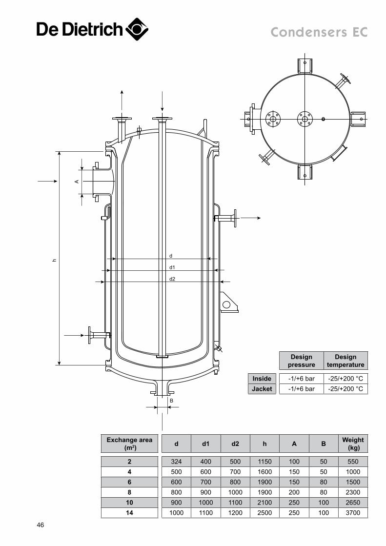
condensers ec
Exchange area (m2) d d1 d2 h A B Weight
(kg)
2 324 400 500 1150 100 50 5504 500 600 700 1600 150 50 10006 600 700 800 1900 150 80 15008 800 900 1000 1900 200 80 2300
10 900 1000 1100 2100 250 100 265014 1000 1100 1200 2500 250 100 3700
d
B
d1
d2
h
A
Design pressure
Design temperature
Inside -1/+6 bar -25/+200 °CJacket -1/+6 bar -25/+200 °C
46
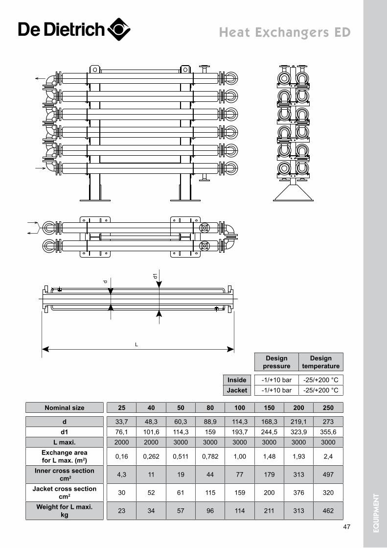
Heat exchangers eD
Nominal size 25 40 50 80 100 150 200 250
d 33,7 48,3 60,3 88,9 114,3 168,3 219,1 273d1 76,1 101,6 114,3 159 193,7 244,5 323,9 355,6
L maxi. 2000 2000 3000 3000 3000 3000 3000 3000Exchange area for L max. (m2) 0,16 0,262 0,511 0,782 1,00 1,48 1,93 2,4
Inner cross section cm2 4,3 11 19 44 77 179 313 497
Jacket cross section cm2 30 52 61 115 159 200 376 320
Weight for L maxi. kg 23 34 57 96 114 211 313 462
d
d1
L
Design pressure
Design temperature
Inside -1/+10 bar -25/+200 °CJacket -1/+10 bar -25/+200 °C
47 equi
pmen
t
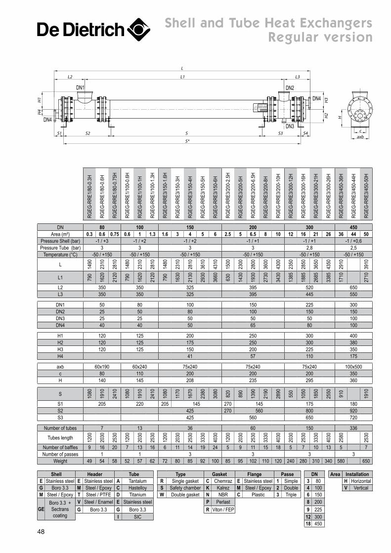
Shell Header Tube Type Gasket Flange Passe DN Area InstallationE Stainless steel E Stainless steel A Tantalum R Single gasket C Chemraz E Stainless steel 1 Simple 3 80 H HorizontalG Boro 3.3 M Steel / Epoxy C Hastelloy S Safety chamber K Kalrez M Steel / Epoxy 2 Double 4 100 V VerticalM Steel / Epoxy T Steel / PTFE D Titanium W Double gasket N NBR C Plastic 3 Triple 6 150
GEBoro 3.3 + Sectrans coating
V Steel / Enamel E Stainless steel P Perlast 8 200G Boro 3.3 G Boro 3,3 R Viton / FEP 9 225
I SIC 12 30018 450
shell and tube Heat exchangers regular version
DN4
DN1
DN3
DN4
DN2
L
L1L2 L3
H1
H4
H2
H3
axbc
H
SS2 S3S1 S4
S*
RGEG
-RRE
1/80
-0.3
H
RGEG
-RRE
1/80
-0.6
H
RGEG
-RRE
1/80
-0.7
5H
RGEG
-RRE
1/10
0-0.
6H
RGEG
-RRE
1/10
0-1H
RGEG
-RRE
1/10
0-1.
3H
RGEG
-RRE
3/15
0-1.
6H
RGEG
-RRE
3/15
0-3H
RGEG
-RRE
3/15
0-4H
RGEG
-RRE
3/15
0-5H
RGEG
-RRE
3/15
0-6H
RGEG
-RRE
3/20
0-2.
5H
RGEG
-RRE
3/20
0-5H
RGEG
-RRE
3/20
0-6.
5H
RGEG
-RRE
3/20
0-8H
RGEG
-RRE
3/20
0-10
H
RGEG
-RRE
3/30
0-12
H
RGEG
-RRE
3/30
0-16
H
RGEG
-RRE
3/30
0-21
H
RGEG
-RRE
3/30
0-26
H
RGEG
-RRE
3/45
0-36
H
RGEG
-RRE
3/45
0-44
H
RGEG
-RRE
3/45
0-50
H
DN 80 100 150 200 300 450Area (m²) 0.3 0.6 0.75 0.6 1 1.3 1.6 3 4 5 6 2.5 5 6.5 8 10 12 16 21 26 36 44 50
Pressure Shell (bar) -1 / +3 -1 / +2 -1 / +2 -1 / +1 -1 / +1 -1 / +0,6Pressure Tube (bar) 3 3 3 3 2,8 2,5
Temperature (°C) -50 / +150 -50 / +150 -50 / +150 -50 / +150 -50 / +150 -50 / +150
L 1490
2310
2810
1480
2310
2810
1480
2310
2810
3610
4310
1500
2300
2800
3600
4300
2350
2850
3650
4350
2910
3910
L1 790
1620
2120
790
1620
2120
790
1630
2130
2930
3660
630
1430
1930
2730
3430
1385
1885
2685
3385
1710
2710
L2 350 350 325 395 520 650L3 350 350 325 395 445 550
DN1 50 80 100 150 225 300DN2 25 50 80 100 150 150DN3 25 25 50 50 50 100DN4 40 40 50 65 80 100
H1 120 125 200 250 300 400H2 120 125 175 250 300 380H3 120 125 150 200 225 350H4 41 57 110 175
axb 60x190 60x240 75x240 75x240 75x240 100x500c 80 110 200 200 200 350H 140 145 208 235 295 360
S 1080
1910
2410
1080
1910
2410
1080
1170
1670
2380
3080
820
890
1390
2190
2890
550
1050
1850
2550
910
1910
S1 205 220 205 145 270 145 175 180S2 425 270 560 800 920S3 425 560 650 720
Number of tubes 7 13 36 60 150 336
Tubes length 1200
2030
2530
1200
2030
2530
1200
2030
2530
3330
4030
1200
2030
2530
3330
4030
2030
2530
3330
4030
2580
2530
Number of baffles 9 16 20 7 13 16 6 11 14 19 24 5 9 11 15 18 5 7 10 13 5 7Number of passes 1 1 3 3 3 3
Weight 49 54 58 52 57 62 72 80 85 92 100 85 95 102 110 120 240 280 310 340 580 650
48
PVEI
-RRE
1/80
-0.3
H
PVEI
-RRE
1/80
-0.6
H
PVEI
-RRE
1/80
-0.7
5H
PVEI
-RRE
1/10
0-0.
3H
PVEI
-RRE
1/10
0-0.
6H
PVEI
-RRE
1/10
0-1H
PVEI
-RRE
1/10
0-1.
3H
PVEI
-RRE
3/15
0-1.
6H
PVEI
-RRE
3/15
0-3H
PVEI
-RRE
3/15
0-4H
PVEI
-RRE
3/15
0-5H
PVEI
-RRE
3/15
0-6H
PVEI
-RRE
3/20
0-2.
5H
PVEI
-RRE
3/20
0-5H
PVEI
-RRE
3/20
0-6.
5H
PVEI
-RRE
3/20
0-8H
PVEI
-RRE
3/14
-10H
PVEI
-RRE
3/25
0-5H
PVEI
-RRE
3/25
0-9H
PVEI
-RRE
3/25
0-11
.5H
PVEI
-RRE
3/25
0-15
H
PVEI
-RRE
3/25
0-18
H
PVEI
-RRE
3/30
0-12
H
PVEI
-RRE
3/30
0-16
H
PVEI
-RRE
3/30
0-21
H
PVEI
-RRE
3/30
0-26
H
PVEI
-RRE
3/40
0-22
H
PVEI
-RRE
3/40
0-28
H
PVEI
-RRE
3/40
0-44
H
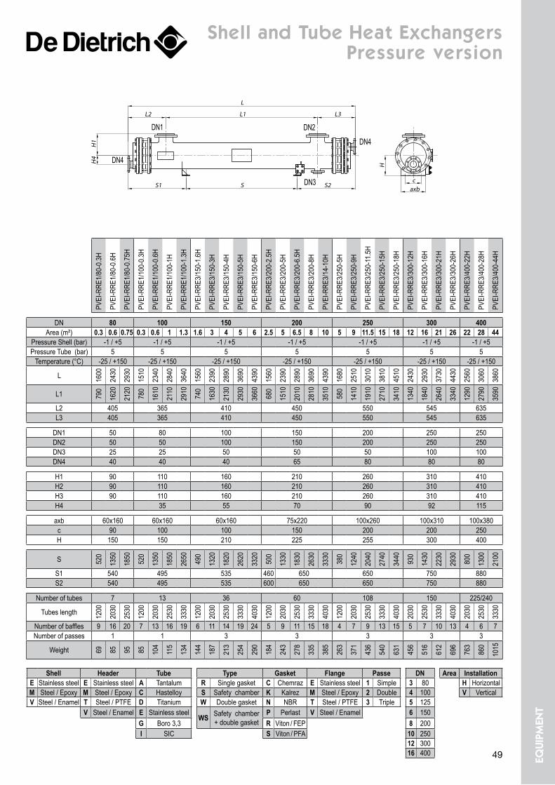
DN 80 100 150 200 250 300 400Area (m²) 0.3 0.6 0.75 0.3 0.6 1 1.3 1.6 3 4 5 6 2.5 5 6.5 8 10 5 9 11.5 15 18 12 16 21 26 22 28 44
Pressure Shell (bar) -1 / +5 -1 / +5 -1 / +5 -1 / +5 -1 / +5 -1 / +5 -1 / +5Pressure Tube (bar) 5 5 5 5 5 5 5
Temperature (°C) -25 / +150 -25 / +150 -25 / +150 -25 / +150 -25 / +150 -25 / +150 -25 / +150
L 1600
2430
2930
1510
2340
2840
3640
1560
2390
2890
3690
4390
1560
2390
2890
3690
4390
1680
2510
3010
3810
4510
2430
2930
3730
4430
2560
3060
3860
L1 790
1620
2120
780
1610
2110
2910
740
1630
2130
2930
3660
680
1510
2010
2810
3510
580
1410
1910
2710
3410
1340
1840
2640
3340
1290
2790
3590
L2 405 365 410 450 550 545 635L3 405 365 410 450 550 545 635
DN1 50 80 100 150 200 250 250DN2 50 50 100 150 200 250 250DN3 25 25 50 50 50 100 100DN4 40 40 40 65 80 80 80
H1 90 110 160 210 260 310 410H2 90 110 160 210 260 310 410H3 90 110 160 210 260 310 410H4 35 55 70 90 92 115
axb 60x160 60x160 60x160 75x220 100x260 100x310 100x380c 90 100 100 150 200 200 250H 150 150 210 225 255 300 400
S 520
1350
1850
520
1350
1850
2650
490
1320
1820
2620
3320
500
1330
1830
2630
3330
380
1240
2040
2740
3440
930
1430
2230
2930
800
1300
2100
S1 540 495 535 460 650 650 750 880S2 540 495 535 600 650 650 750 880
Number of tubes 7 13 36 60 108 150 225/240
Tubes length 1200
2030
2530
1200
2030
2530
3330
1200
2030
2530
3330
4030
1200
2030
2530
3330
4030
1200
2030
2530
3330
4030
2030
2530
3330
4030
2030
2530
3330
Number of baffles 9 16 20 7 13 16 19 6 11 14 19 24 5 9 11 15 18 4 7 9 13 15 5 7 10 13 4 6 7Number of passes 1 1 3 3 3 3 3
Weight 69 85 95 85 104
115
134
144
187
213
254
290
184
243
278
335
385
263
371
436
540
631
456
516
612
696
763
860
1015
Shell Header Tube Type Gasket Flange Passe DN Area InstallationE Stainless steel E Stainless steel A Tantalum R Single gasket C Chemraz E Stainless steel 1 Simple 3 80 H HorizontalM Steel / Epoxy M Steel / Epoxy C Hastelloy S Safety chamber K Kalrez M Steel / Epoxy 2 Double 4 100 V VerticalV Steel / Enamel T Steel / PTFE D Titanium W Double gasket N NBR T Steel / PTFE 3 Triple 5 125
V Steel / Enamel E Stainless steelWS Safety chamber
+ double gasketP Perlast V Steel / Enamel 6 150
G Boro 3,3 R Viton / FEP 8 200I SIC S Viton / PFA 10 250
12 30016 400
shell and tube Heat exchangers pressure version
DN1
DN4
DN3
DN2
DN4
L1
L
L2 L3
H4
H1
SS1 S2caxb
H
49 equi
pmen
t
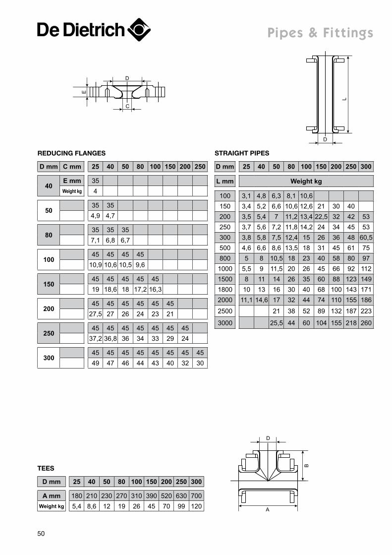
pipes & fittings
C
DE
L
D
D mm 25 40 50 80 100 150 200 250 300
L mm Weight kg
100 3,1 4,8 6,3 8,1 10,6150 3,4 5,2 6,6 10,6 12,6 21 30 40200 3,5 5,4 7 11,2 13,4 22,5 32 42 53250 3,7 5,6 7,2 11,8 14,2 24 34 45 53300 3,8 5,8 7,5 12,4 15 26 36 48 60,5500 4,6 6,6 8,6 13,5 18 31 45 61 75800 5 8 10,5 18 23 40 58 80 971000 5,5 9 11,5 20 26 45 66 92 1121500 8 11 14 26 35 60 88 123 1491800 10 13 16 30 40 68 100 143 1712000 11,1 14,6 17 32 44 74 110 155 186
2500 21 38 52 89 132 187 223
3000 25,5 44 60 104 155 218 260
StraiGht PiPeS
D mm C mm 25 40 50 80 100 150 200 250
40E mm 35Weight kg 4
5035 354,9 4,7
8035 35 357,1 6,8 6,7
10045 45 45 45
10,9 10,6 10,5 9,6
15045 45 45 45 4519 18,6 18 17,2 16,3
20045 45 45 45 45 45
27,5 27 26 24 23 21
25045 45 45 45 45 45 45
37,2 36,8 36 34 33 29 24
30045 45 45 45 45 45 45 4549 47 46 44 43 40 32 30
reDUcinG FlanGeS
A
D
B
D mm 25 40 50 80 100 150 200 250 300
A mm 180 210 230 270 310 390 520 630 700Weight kg 5,4 8,6 12 19 26 45 70 99 120
teeS
50
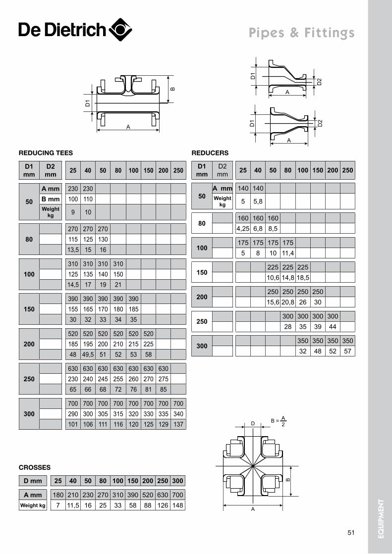
D1 mm
D2 mm 25 40 50 80 100 150 200 250
50
A mm 230 230B mm 100 110Weight
kg 9 10
80270 270 270115 125 13013,5 15 16
100310 310 310 310125 135 140 15014,5 17 19 21
150390 390 390 390 390155 165 170 180 18530 32 33 34 35
200520 520 520 520 520 520185 195 200 210 215 22548 49,5 51 52 53 58
250630 630 630 630 630 630 630230 240 245 255 260 270 27565 66 68 72 76 81 85
300700 700 700 700 700 700 700 700290 300 305 315 320 330 335 340101 106 111 116 120 125 129 137
reDUcinG teeS
pipes & fittings
D1
D1
D2
D2
A
A
D1 mm
D2 mm 25 40 50 80 100 150 200 250
50A mm 140 140Weight
kg 5 5,8
80160 160 1604,25 6,8 8,5
100175 175 175 175
5 8 10 11,4
150225 225 22510,6 14,8 18,5
200250 250 250 25015,6 20,8 26 30
250300 300 300 30028 35 39 44
300350 350 350 35032 48 52 57
reDUcerS
A
B
D B = A2
D mm 25 40 50 80 100 150 200 250 300
A mm 180 210 230 270 310 390 520 630 700Weight kg 7 11,5 16 25 33 58 88 126 148
croSSeS
B
A
D1
51 equi
pmen
t
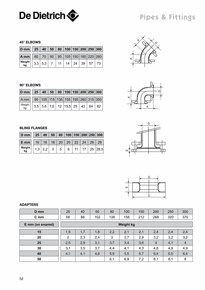
pipes & fittings
E
D
C
D mm 25 40 50 80 100 150 200 250 300C mm 68 88 102 138 158 212 268 320 370
E mm (on enamel) Weight kg
15 1,5 1,7 1,8 2,2 2,1 2,1 2,4 2,4 2,420 2 2,3 2,4 3 2,7 2,9 3,2 3,2 3,225 2,5 2,9 3,1 3,7 3,4 3,6 4 4,1 430 3,1 3,5 3,7 4,4 4,1 4,3 4,8 4,9 4,940 4,1 4,1 4,6 5,9 5,5 5,7 6,4 6,5 6,450 6,1 6,9 7,2 8,1 8,1 8
aDaPterS
D
A
A
D mm 25 40 50 80 100 150 200 250 300
A mm 60 70 80 95 105 150 180 220 260Weight
kg 3,3 5,3 7 11 14 24 39 57 73
45° elBoWS
D
A
A
D mm 25 40 50 80 100 150 200 250 300
A mm 90 105 115 135 155 195 260 315 350Weight
kg 3,5 5,6 7,5 12 15,5 25 43 64 82
90° elBoWS
ED
D mm 25 40 50 80 100 150 200 250 300
E mm 16 16 18 20 20 22 24 26 26Weight
kg 1,3 2,2 3 5 6 11 17 25 28,5
BlinD FlanGeS
52
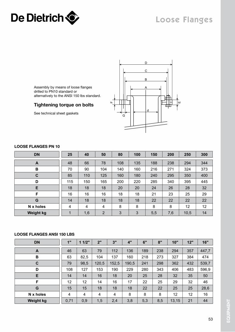
A
d
B
C
D
F
G
E
DN 25 40 50 80 100 150 200 250 300
A 48 66 78 108 135 188 238 294 344B 70 90 104 140 160 216 271 324 373C 85 110 125 160 180 240 295 350 400D 115 150 165 200 220 285 340 395 445E 18 18 18 20 20 24 26 28 32F 16 16 16 18 18 21 23 25 29G 14 18 18 18 18 22 22 22 22
N x holes 4 4 4 8 8 8 8 12 12Weight kg 1 1,6 2 3 3 5,5 7,6 10,5 14
looSe FlanGeS Pn 10
Assembly by means of loose flanges drilled to PN10 standard or alternatively to the ANSI 150 lbs standard.
tightening torque on bolts
See technical sheet gaskets
Loose flanges
looSe FlanGeS anSi 150 lBS
DN 1" 1 1/2" 2" 3" 4" 6" 8" 10" 12" 16"
A 46 63 79 112 136 189 238 294 357 447,7B 63 82,5 104 137 160 218 273 327 384 474C 79 98,5 120,5 152,5 190,5 241 298 362 432 539,7D 108 127 153 190 229 280 343 406 483 596,9E 14 14 16 18 20 25 28 32 35 50F 12 12 14 16 17 22 25 29 32 46G 15 15 18 18 18 22 22 25 25 28,6
N x holes 4 4 4 4 8 8 8 12 12 16Weight kg 0,71 0,9 1,5 2,4 3,8 5,3 8,5 13,15 21 44
53 equi
pmen
t
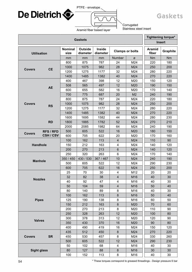
GasketsTightening torque*
Insert
UtilisationNominal
sizeOutside diameter
Inside diameter Clamps or bolts Aramid
fiber Graphite
mm mm mm Number ø Nm Nm
Covers CE
800 875 787 24 M24 220 1801000 1075 982 28 M24 250 2001200 1275 1177 32 M24 280 2201400 1485 1382 40 M24 270 220
Covers
AE
400 467 398 12 M20 150 120508 565 497 12 M20 190 150600 655 582 16 M20 170 140700 775 687 20 M2 240 190
RS
800 875 787 24 M24 220 1801000 1075 982 28 M24 250 2001200 1275 1177 32 M24 280 2201400 1485 1382 40 M24 270 220
RD1600 1695 1582 44 M24 280 2301800 1885 1782 52 M24 270 2102000 2085 1982 64 M24 240 190
Covers RFS / RFD CSH / CSV
500 605 522 16 M20 180 150600 705 622 20 M20 170 160
Handhole100 162 113 4 M24 110 90150 212 163 4 M24 140 120200 270 213 6 M24 140 120
Manhole
250 320 263 6 M24 170 140350 / 450 430 / 530 367 / 467 10 M24 240 190
500 605 522 12 M24 290 230600 705 622 16 M24 250 200
Nozzles
25 70 30 4 M12 20 2032 82 38 4 M16 40 3040 92 47 4 M16 40 3050 104 59 4 M16 50 40
Pipes
80 140 89 8 M16 40 30100 162 113 8 M16 50 40125 190 138 8 M16 60 50150 212 163 8 M20 70 60200 270 213 8 M20 110 90
Valves
250 328 263 12 M20 100 80300 378 313 12 M20 120 90350 430 370 16 M20 90 80400 490 419 16 M24 150 120
Covers SR435 512 450 8 M24 270 220450 530 457 8 M24 330 260500 605 522 12 M24 290 230
Sight glass50 102 68 4 M16 40 3080 127 88 8 M16 30 30
100 152 113 8 M16 40 30
* These torques correspond to greased threadings - Design pressure 6 bar
Aramid fiber based layer
CorrugatedStainless steel insert
PTFE - envelope
gaskets
54
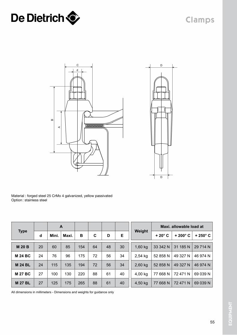
clamps
D
D
d
C
B
A
All dimensions in millimeters - Dimensions and weights for guidance only
TypeA
WeightMaxi. allowable load at
d Mini. Maxi. B C D E + 20° C + 200° C + 250° C
M 20 B 20 60 85 154 64 48 30 1,60 kg 33 342 N 31 185 N 29 714 N
M 24 BC 24 76 96 175 72 56 34 2,54 kg 52 858 N 49 327 N 46 974 N
M 24 BL 24 115 135 194 72 56 34 2,60 kg 52 858 N 49 327 N 46 974 N
M 27 BC 27 100 130 220 88 61 40 4,00 kg 77 668 N 72 471 N 69 039 N
M 27 BL 27 125 175 265 88 61 40 4,50 kg 77 668 N 72 471 N 69 039 N
Material : forged steel 25 CrMo 4 galvanized, yellow passivatedOption : stainless steel
55 equi
pmen
t
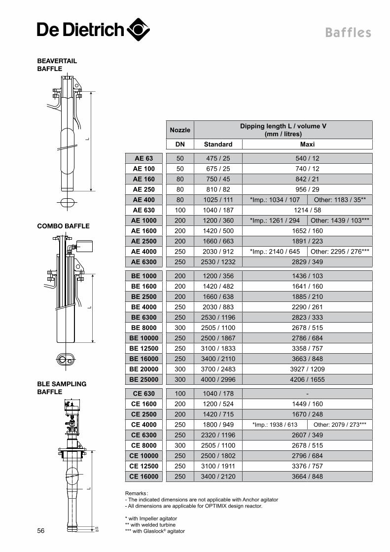
Baffles
L
Nozzle Dipping length L / volume V (mm / litres)
DN Standard Maxi
AE 63 50 475 / 25 540 / 12AE 100 50 675 / 25 740 / 12AE 160 80 750 / 45 842 / 21AE 250 80 810 / 82 956 / 29AE 400 80 1025 / 111 *Imp.: 1034 / 107 Other: 1183 / 35**AE 630 100 1040 / 187 1214 / 58AE 1000 200 1200 / 360 *Imp.: 1261 / 294 Other: 1439 / 103***AE 1600 200 1420 / 500 1652 / 160AE 2500 200 1660 / 663 1891 / 223AE 4000 250 2030 / 912 *Imp.: 2140 / 645 Other: 2295 / 276***AE 6300 250 2530 / 1232 2829 / 349
BE 1000 200 1200 / 356 1436 / 103BE 1600 200 1420 / 482 1641 / 160BE 2500 200 1660 / 638 1885 / 210BE 4000 250 2030 / 883 2290 / 261BE 6300 250 2530 / 1196 2823 / 333BE 8000 300 2505 / 1100 2678 / 515BE 10000 250 2500 / 1867 2786 / 684BE 12500 250 3100 / 1833 3358 / 757BE 16000 250 3400 / 2110 3663 / 848BE 20000 300 3700 / 2483 3927 / 1209BE 25000 300 4000 / 2996 4206 / 1655
CE 630 100 1040 / 178 -CE 1600 200 1200 / 524 1449 / 160CE 2500 200 1420 / 715 1670 / 248CE 4000 250 1800 / 949 *Imp.: 1938 / 613 Other: 2079 / 273***
CE 6300 250 2320 / 1196 2607 / 349CE 8000 300 2505 / 1100 2678 / 515CE 10000 250 2500 / 1802 2796 / 684CE 12500 250 3100 / 1911 3376 / 757CE 16000 250 3400 / 2120 3664 / 848
LL
4530
Remarks :- The indicated dimensions are not applicable with Anchor agitator- All dimensions are applicable for OPTIMIX design reactor.
* with Impeller agitator** with welded turbine*** with Glaslock® agitator
BeaVertail BaFFle
Ble SamPlinG BaFFle
comBo BaFFle
56
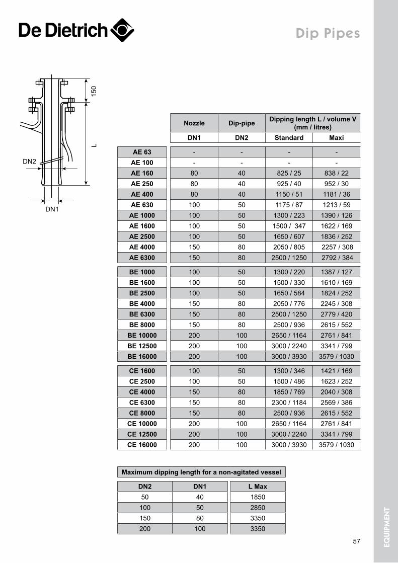
Dip pipes
Nozzle Dip-pipe Dipping length L / volume V (mm / litres)
DN1 DN2 Standard Maxi
AE 63 - - - -AE 100 - - - -AE 160 80 40 825 / 25 838 / 22AE 250 80 40 925 / 40 952 / 30AE 400 80 40 1150 / 51 1181 / 36AE 630 100 50 1175 / 87 1213 / 59AE 1000 100 50 1300 / 223 1390 / 126AE 1600 100 50 1500 / 347 1622 / 169AE 2500 100 50 1650 / 607 1836 / 252AE 4000 150 80 2050 / 805 2257 / 308AE 6300 150 80 2500 / 1250 2792 / 384
BE 1000 100 50 1300 / 220 1387 / 127BE 1600 100 50 1500 / 330 1610 / 169BE 2500 100 50 1650 / 584 1824 / 252BE 4000 150 80 2050 / 776 2245 / 308BE 6300 150 80 2500 / 1250 2779 / 420BE 8000 150 80 2500 / 936 2615 / 552
BE 10000 200 100 2650 / 1164 2761 / 841BE 12500 200 100 3000 / 2240 3341 / 799BE 16000 200 100 3000 / 3930 3579 / 1030
CE 1600 100 50 1300 / 346 1421 / 169CE 2500 100 50 1500 / 486 1623 / 252CE 4000 150 80 1850 / 769 2040 / 308CE 6300 150 80 2300 / 1184 2569 / 386CE 8000 150 80 2500 / 936 2615 / 552
CE 10000 200 100 2650 / 1164 2761 / 841CE 12500 200 100 3000 / 2240 3341 / 799CE 16000 200 100 3000 / 3930 3579 / 1030
Maximum dipping length for a non-agitated vessel
DN2 DN1 L Max50 40 1850100 50 2850150 80 3350200 100 3350
150
L
DN2
DN1
57 equi
pmen
t
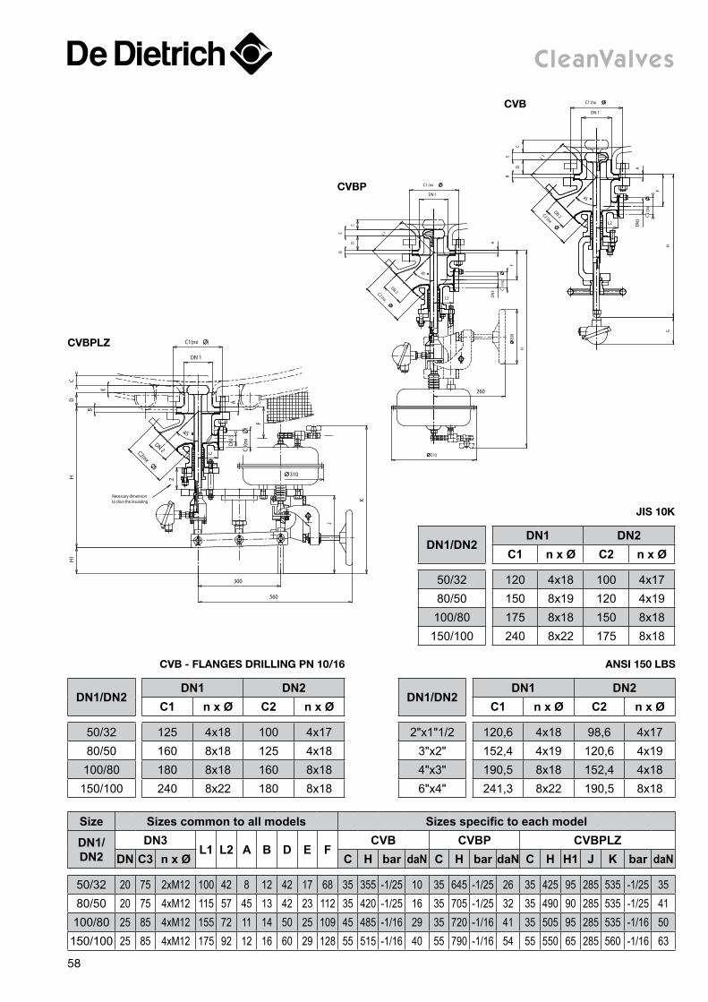
Size Sizes common to all models Sizes specific to each model
DN1/DN2
DN3L1 L2 A B D E F
CVB CVBP CVBPLZDN C3 n x Ø C H bar daN C H bar daN C H H1 J K bar daN
50/32 20 75 2xM12 100 42 8 12 42 17 68 35 355 -1/25 10 35 645 -1/25 26 35 425 95 285 535 -1/25 3580/50 20 75 4xM12 115 57 45 13 42 23 112 35 420 -1/25 16 35 705 -1/25 32 35 490 90 285 535 -1/25 41
100/80 25 85 4xM12 155 72 11 14 50 25 109 45 485 -1/16 29 35 720 -1/16 41 35 505 95 285 535 -1/16 50150/100 25 85 4xM12 175 92 12 16 60 29 128 55 515 -1/16 40 55 790 -1/16 54 55 550 65 285 560 -1/16 63
cleanValves
L2
C2 (nx
)
DN 2
C1 (nx )
DN 1
45
L 1
D
E
C
B
A
F
HG
DN
3
C3 (n
x)
cVB
H
L2
260
45
L1
D
BE
C
AD
N3 C3
(nx
)
F 2
00
310
C1 (nx )
DN 1
DN 2C2 (nx
)
cVBP
L2
D
E
CH
H1
A
F
K
J
300
560
310
DN 2C2(nx
)
DN 1
C1(nx )
DN
3
C3(n
x)
Z
Necessary dimension to shun the insulating
B
45
cVBPlz
DN1/DN2DN1 DN2
C1 n x Ø C2 n x Ø
50/32 125 4x18 100 4x1780/50 160 8x18 125 4x18
100/80 180 8x18 160 8x18150/100 240 8x22 180 8x18
cVB - FlanGeS DrillinG Pn 10/16
DN1/DN2DN1 DN2
C1 n x Ø C2 n x Ø
2"x1"1/2 120,6 4x18 98,6 4x173"x2" 152,4 4x19 120,6 4x194"x3" 190,5 8x18 152,4 4x186"x4" 241,3 8x22 190,5 8x18
anSi 150 lBS
DN1/DN2DN1 DN2
C1 n x Ø C2 n x Ø
50/32 120 4x18 100 4x1780/50 150 8x19 120 4x19100/80 175 8x18 150 8x18150/100 240 8x22 175 8x18
JiS 10K
58
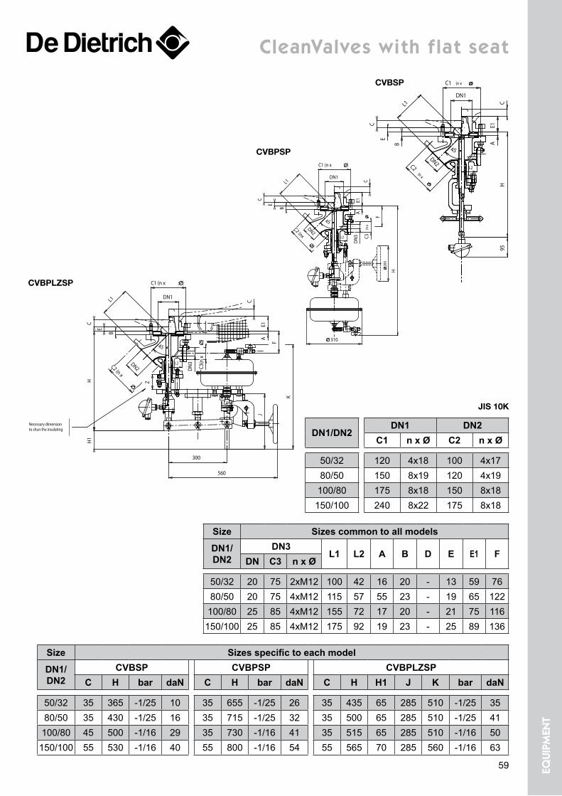
cleanValves with flat seat
Z
Necessary dimension to shun the insulating
DN2C2 (n x
)
DN1
B
C1 (n x )
E
CH
H1
AE1
C
300
560
J
DN
3
C3(n
x) F
K
L1
45
L2
cVBPlzSP
Size Sizes specific to each model
DN1/DN2
CVBSP CVBPSP CVBPLZSPC H bar daN C H bar daN C H H1 J K bar daN
50/32 35 365 -1/25 10 35 655 -1/25 26 35 435 65 285 510 -1/25 3580/50 35 430 -1/25 16 35 715 -1/25 32 35 500 65 285 510 -1/25 41100/80 45 500 -1/16 29 35 730 -1/16 41 35 515 65 285 510 -1/16 50150/100 55 530 -1/16 40 55 800 -1/16 54 55 565 70 285 560 -1/16 63
Size Sizes common to all models
DN1/DN2
DN3L1 L2 A B D E E1 F
DN C3 n x Ø
50/32 20 75 2xM12 100 42 16 20 - 13 59 7680/50 20 75 4xM12 115 57 55 23 - 19 65 122
100/80 25 85 4xM12 155 72 17 20 - 21 75 116150/100 25 85 4xM12 175 92 19 23 - 25 89 136
DN1/DN2DN1 DN2
C1 n x Ø C2 n x Ø
50/32 120 4x18 100 4x1780/50 150 8x19 120 4x19100/80 175 8x18 150 8x18150/100 240 8x22 175 8x18
JiS 10K
DN
3 C3(n
x) F
H
200
310
DN1
C1 (n x )
DN2C2 (nx
)
45
L1
B
E
C
AE1
C
L2
cVBPSP
AB
E
C E1
C
45DN2C2
(n x
)
DN1
C1 (n x )
H95
L1
L2
cVBSP
59 equi
pmen
t

60
NOTE
www.dedietrich.com
The international business group De Dietrich Process Systems is the leading provider of system solutions and reactors for corrosive applications as well as plants for mechanical solid/liquid separation and drying. The system solutions from De Dietrich Process Systems are used in the industrial areas of pharmaceuticals, chemicals and allied industries.
The
info
rmat
ion
cont
aine
d in
this
bro
chur
e is
for
gene
ral g
uida
nce
only
and
is n
ot b
indi
ng. T
he p
roga
mm
s de
scrib
ed h
erei
n m
ay b
e ad
apte
d or
cha
nged
or
disc
ontin
ued
with
out n
otic
e an
d lia
bilit
y. ©
200
9 D
e D
ietr
ich
Pro
cess
Sys
tem
ss. A
ll R
ight
s re
serv
ed. 0
02-0
4/09
DE DIETRICH SASChâteau de ReichshoffenF 67891 Niederbronn CedexPhone +33 3 88 80 26 00Fax +33 3 88 80 26 95www.dedietrich.com
BENELUX
De Dietrich Process Systemss N.V.B - Heverlee-LeuvenPhone +32 16 40 5000Fax +32 16 40 [email protected]
BRAZIL
De Dietrich Do Brasil LtdaSão PauloPhone +55 11 6703 7380Fax +55 11 6702 [email protected]
CHINA
De Dietrich Process Systemss Co. LtdWuxiPhone +86 510 8855 7500Fax +86 510 8855 [email protected]
FRANCE
De Dietrich S.A.S.ZinswillerPhone +33 3 88 53 23 00Fax +33 88 3 53 23 [email protected]
De Dietrich S.A.S.CourcouronnesPhone +33 1 69 47 04 00Fax +33 1 69 47 04 [email protected]
De Dietrich Process Systems Semur S.A.S.Semur-en-AuxoisPhone +33 3 80 97 12 23Fax +33 3 80 97 07 [email protected]
GERMANY
De Dietrich Process Systemss GmbHMainzPhone +49 6131 9704 0Fax +49 6131 9704 [email protected]
GREAT BRITAIN
De Dietrich Process Systemss LtdStaffordPhone +44 1785 609 900Fax +44 1785 609 [email protected]
INDIA
De Dietrich Process Systemss (India) Pvt,LtdMumbaiPhone +91 22 28 505 794Fax +91 22 28 505 [email protected]
IRELAND
De Dietrich Process Systemss Ireland LtdShannonPhone +353 61 366925Fax +353 61 [email protected]
ITALY
De Dietrich Process Systemss SrlSan Dona’ Di Piave (VE)Phone +39 421 222 128Fax +39 421 224 212 [email protected]
RUSSIA
De Dietrich Rep. OfficeMoscowPhone +7 495 739 2013Fax +7 495 739 [email protected]
SINGAPORE
De Dietrich Singapore (PTE) LtdSingaporePhone +65 68 61 12 32Fax +65 68 61 61 [email protected]
SOUTH AFRICA
De Dietrich South Africa (PTY) LtdDunswartPhone +27 11 918 4131Fax +27 11 918 [email protected]
SPAIN
De Dietrich Equipos Quimicos S.L.BarcelonaPhone +34 93 21 88 613Fax +34 93 21 84 [email protected]
SWITZERLAND
De Dietrich Process Systemss AGLiestalPhone +41 61 925 11 11Fax +41 61 921 99 [email protected]
UNITED STATES
De Dietrich Process Systemss Inc.Mountainside, NJPhone +1 908 317 2585Fax +1 908 889 [email protected]
Charlotte, NCPhone +1 704 587 04 40Fax +1 704 588 68 [email protected]
Valb
lor-
Gro
upe
Gra
phiq
ue F
-67
Illki
rch
9041
331