date: document release and change form · 1.doc no: rpp-spec-61269 rev. 01 2. title: ... plc...
TRANSCRIPT

1 SPF-001 (Rev.D1)
DOCUMENT RELEASE AND CHANGE FORMPrepared For the U.S. Department of Energy, Assistant Secretary for Environmental ManagementBy Washington River Protection Solutions, LLC., PO Box 850, Richland, WA 99352Contractor For U.S. Department of Energy, Office of River Protection, under Contract DE-AC27-08RV14800
TRADEMARK DISCLAIMER: Reference herein to any specific commercial product, process, or service by trade name, trademark, manufacturer, or otherwise, does not necessarily constitute or imply its endorsement, recommendation, or favoring by the United States government or any agency thereof or its contractors or subcontractors. Printed in the United States of America.
Release Stamp
1. Doc No: RPP-SPEC-61269 Rev. 01
2. Title:Level 2 Specification for the 241-A Tanks Waste Retrieval Systems
3. Project Number:T2R41
☐ N/A 4. Design Verification Required:
☐ Yes ☒ No5. USQ Number: ☒ N/A
N/A-8
6. PrHA Number Rev. ☐ N/APRHA-02042 00PRHA-02043 00PRHA-02044 00PRHA-02045 00PRHA-02046 00PRHA-02047 00
Clearance Review Restriction Type:public
7. Approvals
Title Name Signature DateClearance Review AARDAL, JANIS D AARDAL, JANIS D 11/28/2017Design Authority ANDERSON, CRAIG H ANDERSON, CRAIG H 11/13/2017Checker EIHOLZER, SEAN M EIHOLZER, SEAN M 11/07/2017Document Control Approval PORTER, MARY PORTER, MARY 11/28/2017Originator SINCLAIR, TREVOR J SINCLAIR, TREVOR J 11/13/2017Other Approver HALL, BRANDON HALL, BRANDON 11/13/2017PrHA Lead SMITH, RYAN D SMITH, RYAN D 11/13/2017Responsible Engineering Manager CARPENTER, KEITH E CARPENTER, KEITH E 11/14/2017USQ Evaluator SMITH, RYAN D SMITH, RYAN D 11/13/2017
8. Description of Change and Justification
The initial release of this document did not include the technical requirements baseline of tanks 241-A-104 and 241-A-105. Revision 1 of this document includes the requirements for tanks 241-A-104 and 241-A-105.
9. TBDs or Holds ☒ N/A
10. Related Structures, Systems, and Components
a. Related Building/Facilities ☐ N/A b. Related Systems ☐ N/A c. Related Equipment ID Nos. (EIN) ☒ N/A
241-A 241-EDS241-RW241-SA241-WST241-WT
11. Impacted Documents – Engineering ☒ N/A
Document Number Rev. Title
12. Impacted Documents (Outside SPF):
N/A
13. Related Documents ☒ N/A
Document Number Rev. Title
14. Distribution
Name OrganizationALLEN, MARK EANDERSON, CRAIG H C-FARM RETRIEVAL ENGRNGANDROS, BENJAMIN E A/AX RETRIEVAL ENGRNGATKINS, LARRY B CONSTRUCTION & COMMISSIONINGBOETTGER, JEFF C-FARM RETRIEVAL ENGRNGBRYDEN, MICHAEL J C-FARM RETRIEVAL ENGRNGCARPENTER, KEITH E C-FARM RETRIEVAL ENGRNGCOOK, SHAUN MEIHOLZER, SEAN M C-FARM RETRIEVAL ENGRNGESVELT, CHAD A RETRIEVAL WORK PLANNINGGOODNIGHT, TYLER KHALL, BRANDON C-FARM RETRIEVAL ENGRNGHANSON, CARL E AY-102 RETRIEVAL ENGRNG
RPP-SPEC-61269 Rev.01 11/28/2017 - 1:24 PM 1 of 71
Nov 28, 2017DATE:

DOCUMENT RELEASE AND CHANGE FORM Doc No: RPP-SPEC-61269 Rev. 01
2 SPF-001 (Rev.D1)
14. Distribution
Name OrganizationHOPKINS, GARY P R&C CONSTRUCTIONHULL, KEVIN J ELECTRICAL/AREA/242A-EVAP ENGPARKMAN, DAVID B MARS-BASED RETRIEVAL ENGRNGSINCLAIR, TREVOR J C-FARM RETRIEVAL ENGRNGSNYDER, JOSHUA J A/AX RETRIEVAL ENGRNGZENTLER, TIMOTHY W
RPP-SPEC-61269 Rev.01 11/28/2017 - 1:24 PM 2 of 71

A-6002-767 (REV 3)
RPP-SPEC-61269, Rev. 1
Level 2 Specification for the 241-A Tanks WasteRetrieval Systems
Author Name:
KA White
ARES Corporation for Washington River Protection Solutions, LLC
Richland, WA 99352U.S. Department of Energy Contract DE-AC27-08RV14800
EDT/ECN: DRCF UC:
Cost Center: Charge Code:
B&R Code: Total Pages: 71
Key Words: 241-A, 241-A-101, 241-A-102, 241-A-103, 241-A-104, 241-A-105, 241-A-106, 241-AP-101, specification, design, performance, SST, WRS, retrieval, sludge, slurry, sluicing, hard heel, saltcake, water, supernate, supernatant, dissolution, mechanical waste gathering, dry retrieval system
Abstract: This document defines the functions, performance, and interface requirements and design constraints to support the design of a waste retrieval system for 241-A Single-Shell Tanks using modified sluicing-saltcake dissolution and/or hard heel retrieval.
TRADEMARK DISCLAIMER. Reference herein to any specific commercial product, process, or service by trade name, trademark, manufacturer, or otherwise, does not necessarily constitute or imply its endorsement, recommendation, or favoring by the United States Government or any agency thereof or its contractors or subcontractors.
Release Approval Date Release Stamp
Approved For Public Release
RPP-SPEC-61269 Rev.01 11/28/2017 - 1:24 PM 3 of 71
By Janis Aardal at 2:04 pm, Nov 28, 2017
Nov 28, 2017DATE:

RPP-SPEC-61269, Rev. 1
i
LEVEL 2 SPECIFICATION FOR THE 241-A TANKS WASTE RETRIEVAL SYSTEMS
February 2017
Revision 0 prepared by
ARES CorporationEnergy Services Division1100 Jadwin Avenue, Suite 400Richland, Washington 99352
(509) 946-3300
prepared for
Washington River Protection Solutions, LLC
Revision 1 prepared by
Trevor SinclairWashington River Protection Solutions, LLC
RPP-SPEC-61269 Rev.01 11/28/2017 - 1:24 PM 4 of 71

RPP-SPEC-61269, Rev. 1
ii
TABLE OF CONTENTS
1.0 SCOPE ....................................................................................................................................11.1 Description.....................................................................................................................11.2 Document Overview ......................................................................................................1
2.0 APPLICABLE DOCUMENTS ..............................................................................................32.1 Government Documents ................................................................................................32.2 Non-Government Documents ........................................................................................52.3 Non-Government Non-Code of Record Documents......................................................6
3.0 SYSTEM CHARACTERISTICS .........................................................................................103.1 System Functions and Function Performance Requirements ......................................11
3.1.1 Complete Waste Compatibility Assessment/Process Control Plan .................113.1.2 Sluice and Dissolution .....................................................................................133.1.3 Pump Slurry to DST.........................................................................................17
3.2 System Interfaces and Interface Performance Requirements ......................................233.2.1 SST Electrical Power System ..........................................................................233.2.2 SST Raw Water System...................................................................................233.2.3 SST Service Air System (East Area) ...............................................................253.2.4 SST Chemical System......................................................................................263.2.5 DST Electrical Power Subsystem ....................................................................263.2.6 DST Confinement Subsystem..........................................................................263.2.7 System Controls Subsystem.............................................................................263.2.8 SST Ventilation Subsystem .............................................................................273.2.9 SST Subsystem ................................................................................................283.2.10 DST Subsystem................................................................................................28
3.3 Design Requirements ...................................................................................................283.3.1 Safety ...............................................................................................................293.3.2 Environmental Conditions ...............................................................................313.3.3 Human Performance/Human Factors Engineering ..........................................343.3.4 Personnel and Training ....................................................................................343.3.5 Control System.................................................................................................343.3.6 System Design Life..........................................................................................363.3.7 Materials ..........................................................................................................373.3.8 Security ............................................................................................................383.3.9 Decontamination and Decommissioning .........................................................383.3.10 Electromagnetic Radiation...............................................................................393.3.11 Nameplate and Product Marking .....................................................................393.3.12 Electrical Component Requirements ...............................................................393.3.13 Mechanical Component Requirements ............................................................403.3.14 Raw Water Component Requirements.............................................................423.3.15 Air and Gas Treatment System Design............................................................433.3.16 Waste Transfer Structures................................................................................433.3.17 Load Limitations..............................................................................................433.3.18 Equipment Removal Component Requirements..............................................443.3.19 In-Farm Camera Requirements........................................................................45
RPP-SPEC-61269 Rev.01 11/28/2017 - 1:24 PM 5 of 71

RPP-SPEC-61269, Rev. 1
iii
3.3.20 Above-Grade Transfer Line Radiation Monitoring Well Requirements ...................................................................................................45
3.4 System RAMI Requirements .......................................................................................463.4.1 Reliability.........................................................................................................463.4.2 Availability ......................................................................................................463.4.3 Maintainability.................................................................................................463.4.4 Inspectability....................................................................................................46
3.5 System Other Requirements ........................................................................................463.5.1 Infrastructure Requirements.............................................................................463.5.2 Operating Requirements ..................................................................................463.5.3 Maintenance Requirements..............................................................................473.5.4 Spare Capacity and Interchangeability ............................................................473.5.5 Transportability................................................................................................483.5.6 Hoisting and Rigging Requirements................................................................493.5.7 Qualification Tests ...........................................................................................503.5.8 Government-Loaned and -Furnished Property ................................................503.5.9 Solid Waste ......................................................................................................503.5.10 Solid Waste Generated.....................................................................................503.5.11 Documentation.................................................................................................513.5.12 Workmanship...................................................................................................513.5.13 Civil Surveys....................................................................................................513.5.14 Constructability................................................................................................51
4.0 SYSTEM DESCRIPTION....................................................................................................514.1 Operating Concept .......................................................................................................514.2 Maintenance Concept...................................................................................................524.3 Characteristics of System Subelements .......................................................................52
4.3.1 Retrieval and Conveyance Subsystem.............................................................524.3.2 Waste Transfer Line Subsystem ......................................................................524.3.3 SST Ventilation System...................................................................................534.3.4 Monitor and Control Subsystem ......................................................................534.3.5 Electrical Power Distribution (241-A Tank Farm) ..........................................534.3.6 Raw Water Distribution (241-A Tank Farm)...................................................534.3.7 Service Air Distribution (241-A Tank Farm) ..................................................544.3.8 DST Utilities Subsystems Subsystem..............................................................54
5.0 DESIGN VERIFICATION...................................................................................................54
6.0 NOTES..................................................................................................................................546.1 241-A Tank Farm Construction ...................................................................................54
7.0 APPENDIXES ......................................................................................................................58
LIST OF APPENDICES
Appendix A – Functional Flow Block Diagram
RPP-SPEC-61269 Rev.01 11/28/2017 - 1:24 PM 6 of 71

RPP-SPEC-61269, Rev. 1
iv
LIST OF FIGURES
Figure 1-1. SST Waste Retrieval System. ......................................................................................2
Figure 3-1. Waste Retrieval System – Major Subsystems and Interfaces. ...................................24
Figure 6-1. Typical Riser Layout for 241-A Tanks. .....................................................................56
Figure 6-2. Typical 241-A Tank Cross-Section Sketch................................................................57
LIST OF TABLES
Table 2-1. Government Documents. (2 sheets) .............................................................................3
Table 2-2. Non-Government Documents........................................................................................5
Table 2-3. Non-Government Non-Code of Record Documents. (4 sheets)...................................6
Table 3-1. Physical Properties of 241-A Tank Waste. (2 sheets) ................................................14
Table 3-2. Physical Properties of DST Receiver Tank 241-AP-101. ...........................................16
Table 3-3. In-Tank Radiological Exposure Rates.........................................................................32
RPP-SPEC-61269 Rev.01 11/28/2017 - 1:24 PM 7 of 71
RPP-SPEC-61269, Rev. 1
v
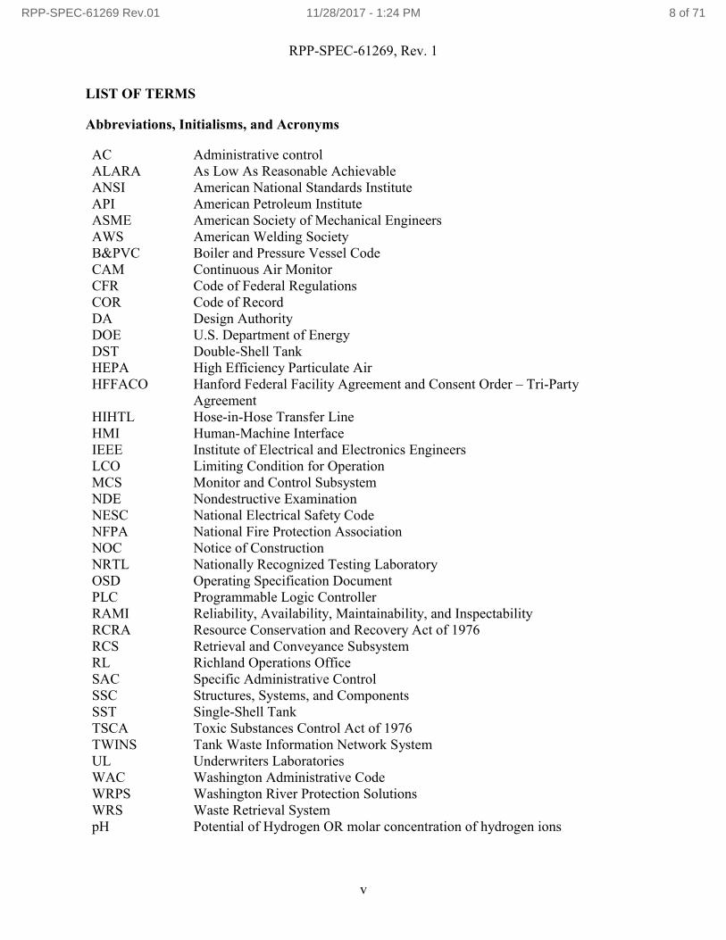
LIST OF TERMS
Abbreviations, Initialisms, and Acronyms
AC Administrative controlALARA As Low As Reasonable AchievableANSI American National Standards InstituteAPI American Petroleum InstituteASME American Society of Mechanical EngineersAWS American Welding SocietyB&PVC Boiler and Pressure Vessel CodeCAM Continuous Air MonitorCFR Code of Federal RegulationsCOR Code of RecordDA Design AuthorityDOE U.S. Department of EnergyDST Double-Shell TankHEPA High Efficiency Particulate AirHFFACO Hanford Federal Facility Agreement and Consent Order – Tri-Party
AgreementHIHTL Hose-in-Hose Transfer LineHMI Human-Machine InterfaceIEEE Institute of Electrical and Electronics EngineersLCO Limiting Condition for OperationMCS Monitor and Control SubsystemNDE Nondestructive ExaminationNESC National Electrical Safety CodeNFPA National Fire Protection AssociationNOC Notice of ConstructionNRTL Nationally Recognized Testing LaboratoryOSD Operating Specification DocumentPLC Programmable Logic ControllerRAMI Reliability, Availability, Maintainability, and InspectabilityRCRA Resource Conservation and Recovery Act of 1976RCS Retrieval and Conveyance SubsystemRL Richland Operations OfficeSAC Specific Administrative ControlSSC Structures, Systems, and ComponentsSST Single-Shell TankTSCA Toxic Substances Control Act of 1976TWINS Tank Waste Information Network SystemUL Underwriters LaboratoriesWAC Washington Administrative CodeWRPS Washington River Protection SolutionsWRS Waste Retrieval SystempH Potential of Hydrogen OR molar concentration of hydrogen ions
RPP-SPEC-61269 Rev.01 11/28/2017 - 1:24 PM 8 of 71
RPP-SPEC-61269, Rev. 1
vi
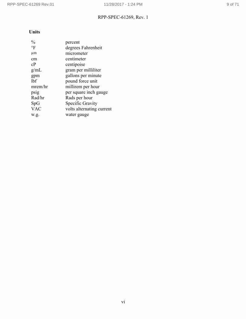
Units
% percent°F degrees Fahrenheitµm micrometercm centimetercP centipoiseg/mL gram per millilitergpm gallons per minutelbf pound force unitmrem/hr millirem per hourpsig per square inch gaugeRad/hr Rads per hourSpG Specific GravityVAC volts alternating currentw.g. water gauge
RPP-SPEC-61269 Rev.01 11/28/2017 - 1:24 PM 9 of 71

RPP-SPEC-61269, Rev. 0
1
1.0 SCOPE
This specification establishes the functional, interface, performance, and design requirements for the 241-A Tanks Waste Retrieval Systems.
1.1 Description
This Level 2 Specification establishes requirements for the Waste Retrieval System (WRS) to remove radioactive waste from the single-shell tanks (SST) in 241-A Farm and to transfer the waste to a double-shell tank (DST). Projects have been established to ensure that waste retrieval equipment, transfer lines, pumps, pit modifications, and associated equipment and instrumentation are available for the retrieval of waste from the SST and subsequent transfer to a DST. In the process, the systems provided by the project may also support closure of the tank.
1.2 Document Overview
This Level 2 Specification identifies the following requirements for the WRS:
The system description (conceptual block diagram);
Interface definition and required functional, performance, physical, reliability and maintainability characteristics;
Environmental operating conditions;
Design and construction;
Environmental, safety, and quality; and
Logistics (maintenance, supply support, etc.).
This specification documents the technical requirements baseline for the 241-A-101 WRS, 241-A-102 WRS, 241-A-103 WRS, 241-A-104 WRS, 241-A-105 WRS, and 241-A-106 WRS. This specification will be updated, as required, throughout the life-cycle design phases of the WRS. The WRS hardware as depicted in Figure 1-1 for a sluicing retrieval system and shall satisfy the requirements within this specification. The WRS hardware as depicted in Figure 1-2 for a dry retrieval system and shall satisfy the requirements within this specification.
RPP-SPEC-61269 Rev.01 11/28/2017 - 1:24 PM 10 of 71

RPP-SPEC-61269, Rev. 0
2
Figure 1-1. SST Sluicing Waste Retrieval System.
Figure 1-2. SST Dry Waste Retrieval System.
RPP-SPEC-61269 Rev.01 11/28/2017 - 1:24 PM 11 of 71

RPP-SPEC-61269, Rev. 0
3
The following definitions apply to this Level 2 Specification:
Shall – denotes a requirement.
Must – denotes a requirement.
Should – denotes a recommendation. If a “should” recommendation cannot be satisfied, justification of an alternative design solution shall be submitted to the Design Authority for approval.
Will – denotes a statement of fact.
May – denotes a “permissive” for a stated action, or denotes a possible outcome, depending on the context of the verbiage.
2.0 APPLICABLE DOCUMENTS
2.1 Government Documents
The following documents, of the exact issue shown in Table 2-1, form a part of this specification to the extent specified herein and establish the Code of Record (COR).
Table 2-1. Government Documents. (3 sheets)
Document Number Reference
Federal Requirements
10 CFR 830 “Nuclear Safety Management,” Code of Federal Regulations, as amended.
10 CFR 835 “Occupational Radiation Protection,” Code of Federal Regulations, as amended.
29 CFR 1910 29 CFR 1910, “Occupational Safety and Health Standards (OSHA),” Code of Federal Regulations, as amended.
29 CFR 1926 29 CFR 1926, “Safety and Health Regulations for Construction,” Code of Federal Regulations, as amended.
40 CFR 265 40 CFR 265, “Interim Status Standards for Owners and Operators of Hazardous Waste Treatment, Storage, and Disposal Facilities,” Code of Federal Regulations, as amended.
15 USC 2601 (TSCA) Toxic Substances Control Act of 1976 (TSCA), et seq.
42 USC 6901 (RCRA) Resource Conservation and Recovery Act of 1976 (RCRA), et seq.
Executive Orders
HFFACO Hanford Federal Facility Agreement and Consent Order – Tri-Party Agreement, 1989, 2 vols., State of Washington Department of Ecology, U.S. Environmental Protection Agency, and U.S. Department of Energy(DOE), Olympia, Washington (hereinafter referred to as HFFACO).
RPP-SPEC-61269 Rev.01 11/28/2017 - 1:24 PM 12 of 71

RPP-SPEC-61269, Rev. 0
4
Table 2-1. Government Documents. (3 sheets)
Document Number Reference
DOE Orders, Standards, and Directives
DOE O 420.1C Facility Safety, U.S. Department of Energy, Washington, D.C.
DOE-STD-1066-2016 DOE Standard Fire Protection, U.S. Department of Energy, Washington, D.C.
Richland Operations Office (RL) and Office of River Protection Implementing Procedures
DOE-0336 Hanford Site Lockout/Tagout Procedure, U.S. Department of Energy, Richland Operations Office, Richland, Washington.
DOE-0344 Hanford Site Excavating, Trenching and Shoring Procedure (HSETSP),U.S. Department of Energy, Richland Operations Office, Richland, Washington.
DOE-0359 Hanford Site Electrical Safety Program (HSESP), U.S. Department of Energy, Richland Operations Office, Richland, Washington.
DOE-RL-92-36 Hanford Site Hoisting and Rigging Manual, U.S. Department of Energy, Richland Operations Office, Richland, Washington.
Washington State Documents
ALARACT 01.11 Tank Farm ALARACT Demonstration for Pit Access, Washington State Department of Health, Olympia, Washington.
ALARACT 06.11 Tank Farm ALARACT Demonstration for Pit Access, Washington State Department of Health, Olympia, Washington.
ALARACT 13.11 Tank Farm ALARACT Demonstration for Installation, Operation, and Removal of Tank Equipment, Washington State Department of Health, Olympia, Washington.
ALARACT 14.11 Tank Farm ALARACT Demonstration for Pit Work, Washington State Department of Health, Olympia, Washington.
AIR-12-3071 Categorical Tank Farm Facility Waste Retrieval and Closure: Phase II Waste Retrieval Operations, Notice of Construction (NOC) ID 825, approved 2/23/2012.
AIR-12-3311 Categorical Tank Farm Facility Waste Retrieval and Closure: Phase I – Site Preparation and System Installation, NOC ID 852, approved 2/23/2012.
Order #DE05NWP-0022 “Non-Radioactive Air Emissions Notice of Construction Approval Order Conditions and Restrictions,” approved July 31, 2007.
WAC 173-303-640 WAC 173-303-640, “Tank Systems,” Washington Administrative Code, as amended.
WAC 173-400 WAC 173-400, “General Regulations for Air Pollution Sources,” Washington Administrative Code, as amended.
1 Hanford Air Operating Permit 00-05-006 Renewal 2 - Revision B, Queried December 15, 2016, [Washington Department of Ecology, Hanford Air Operating Permit, Attachment 2: Health Permitting Conditions, Effective Date August 1, 2016, Permit Number: 00-05-006, Renewal 2 – Rev. B], http://www.ecy.wa.gov/programs/nwp/permitting/AOP/renewal/two/Revision_B/07_28_16/Att-2/Att-2_R2RB.pdf2 AR/PIR Record Details for Record Accession Number ”DA05508701,” Queried December 15, 2016, [Washington State Department of Ecology, Approval of Criteria and Toxic Air Emissions Notice of Construction NOC Application Hanford Single-Shell Tank Waste Retrieval, July 31, 2007, Notice Of Construction Approval Order No. DE05NWP-002, Rev. 2], http://pdw.hanford.gov/arpir/index.cfm/viewDoc?accession=DA05508701
RPP-SPEC-61269 Rev.01 11/28/2017 - 1:24 PM 13 of 71

RPP-SPEC-61269, Rev. 0
5
Table 2-1. Government Documents. (3 sheets)
Document Number Reference
WAC 173-460 WAC 173-460, “Controls for New Sources of Toxic Air Pollutants,” Washington Administrative Code, as amended.
WAC 246-247 WAC 246-247, “Radiation Protection—Air Emissions,” Washington Administrative Code, as amended.
WAC 246-290-490 WAC 246-290-490, “Cross Connection Control,” Washington Administrative Code, as amended.
2.2 Non-Government Documents
The following documents, of the exact issue shown in Table 2-2, form a part of this specification to the extent specified herein and establish the Code of Record (COR).
Table 2-2. Non-Government Documents. (2 sheets)
Document Number Reference
Industry Consensus Codes and Standards
ANSI Y32.9 “American National Standard Graphic Symbols for Electrical Wiring and Layout Diagrams Used in Architecture and Building Construction,” American National Standards Institute (ANSI), New York, New York.
ANSI/IEEE C2 (NESC) “National Electrical Safety Code,” American National Standards Institute/Institute of Electrical and Electronics Engineers (IEEE), New York, New York.
API 610 “Centrifugal Pumps for Petroleum, Petrochemical and Natural Gas Industries,” American Petroleum Institute (API), Washington, D.C.
ASME B&PVC “Boiler and Pressure Vessel Code” (B&PVC), American Society of Mechanical Engineers (ASME), New York, New York.
ASME B30.20 “Below-the-Hook Lifting Devices,” American Society of Mechanical Engineers, New York, New York.
ASME B31.1 “Power Piping,” American Society of Mechanical Engineers, New York, New York.
ASME B31.3 “Process Piping,” American Society of Mechanical Engineers, New York, New York.
ASME B31.9 “Building Service Piping,” American Society of Mechanical Engineers, New York, New York.
ASME BTH-1 “Design of Below-the-Hook Lifting Devices,” American Society of Mechanical Engineers, New York, New York.
ASME NQA-1 “Quality Assurance Requirements for Nuclear Facility Applications,”American Society of Mechanical Engineers, New York, New York.
AWS D1.1 “Structural Welding Code – Steel,” American Welding Society (AWS), Miami, Florida.
AWS D1.3 “Structural Welding Code – Sheet Steel,” American Welding Society, Miami, Florida.
AWS D1.6 “Structural Welding Code – Stainless Steel,” American Welding Society, Miami, Florida.
RPP-SPEC-61269 Rev.01 11/28/2017 - 1:24 PM 14 of 71

RPP-SPEC-61269, Rev. 0
6
Table 2-2. Non-Government Documents. (2 sheets)
Document Number Reference
IEEE 315 “IEEE Graphic Symbols for Electrical and Electronics Diagrams (Including Reference Designation Letters),” IEEE Operations Center, Piscataway, New Jersey.
NFPA 70®3 “National Electrical Code®3,” National Fire Protection Association (NFPA), Quincy, Massachusetts.
UL 508A “Standard for Industrial Control Panels,” Underwriters Laboratories (UL), Northbrook, Illinois.
2.3 Non-Government Non-Code of Record Documents
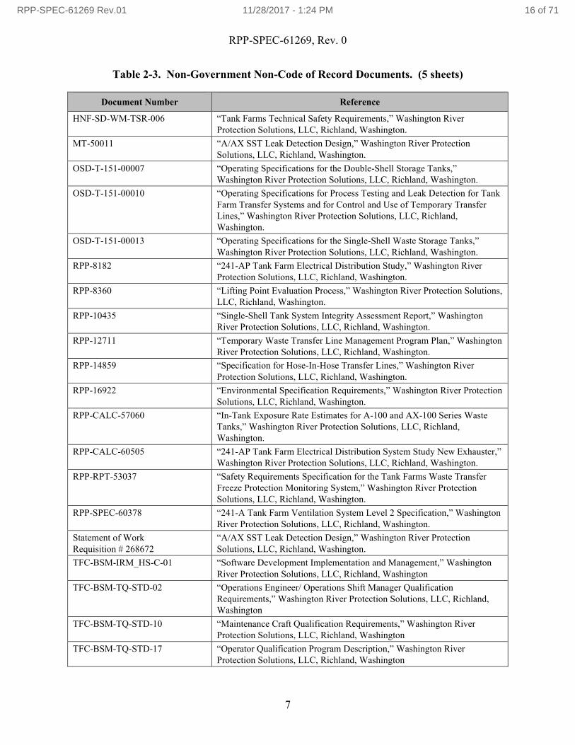
The following documents, of the exact issue shown in Table 2-3 are utilized in or referenced by this document, form a part of this specification to the extent specified herein, but are not considered COR documents.
Table 2-3. Non-Government Non-Code of Record Documents. (5 sheets)
Document Number Reference
WRPS Documents
HNF-2962 “A List of EMI/EMC Requirements,” Washington River Protection Solutions, LLC, Richland, Washington
HNF-4157 “Double-Shell Tank Utilities Specification,” Washington River Protection Solutions, LLC, Richland, Washington
HNF-4712 “Load Requirements for Maintaining Structural Integrity of Hanford Single-Shell Tanks During Waste Feed Delivery and Retrieval Activities,” Lockheed Martin Hanford Corporation, Richland, Washington.
HNF-5183 “Tank Farms Radiological Control Manual (TFRCM),” Washington River Protection Solutions, LLC, Richland, Washington.
HNF-IP-12664 “Tank Farms Operations Administrative Controls,” Washington River Protection Solutions, LLC, Richland, Washington.
HNF-SD-WM-OCD-015 “Tank Farms Waste Transfer Compatibility Program,” Washington River Protection Solutions, LLC, Richland, Washington.
HNF-SD-WM-SP-012 “Tank Farm Contractor Operations and Utilization Plan,” Washington River Protection Solutions, LLC, Richland, Washington.
HNF-SD-WM-TRD-007 “System Specification for the Double-Shell Tank System,” Washington River Protection Solutions, LLC, Richland, Washington.
3 NFPA 70 and National Electrical Code are registered trademarks of the National Fire Protection Association, Quincy, Massachusetts. 4 Tank Farms Operations Administrative Controls (HNF-IP-1266), Queried December 15, 2016, [Washington River Protection Solutions, Tank Farms Operations Administrative Controls, HNF-IP-1266, as amended], http://toc.wrps.rl.gov/rapidweb/PRO/index.cfm?pageNum=243
RPP-SPEC-61269 Rev.01 11/28/2017 - 1:24 PM 15 of 71
RPP-SPEC-61269, Rev. 0
7
Table 2-3. Non-Government Non-Code of Record Documents. (5 sheets)
Document Number Reference
HNF-SD-WM-TSR-006 “Tank Farms Technical Safety Requirements,” Washington River Protection Solutions, LLC, Richland, Washington.
MT-50011 “A/AX SST Leak Detection Design,” Washington River Protection Solutions, LLC, Richland, Washington.
OSD-T-151-00007 “Operating Specifications for the Double-Shell Storage Tanks,” Washington River Protection Solutions, LLC, Richland, Washington.
OSD-T-151-00010 “Operating Specifications for Process Testing and Leak Detection for Tank Farm Transfer Systems and for Control and Use of Temporary Transfer Lines,” Washington River Protection Solutions, LLC, Richland, Washington.
OSD-T-151-00013 “Operating Specifications for the Single-Shell Waste Storage Tanks,” Washington River Protection Solutions, LLC, Richland, Washington.
RPP-8182 “241-AP Tank Farm Electrical Distribution Study,” Washington River Protection Solutions, LLC, Richland, Washington.
RPP-8360 “Lifting Point Evaluation Process,” Washington River Protection Solutions, LLC, Richland, Washington.
RPP-10435 “Single-Shell Tank System Integrity Assessment Report,” Washington River Protection Solutions, LLC, Richland, Washington.
RPP-12711 “Temporary Waste Transfer Line Management Program Plan,” Washington River Protection Solutions, LLC, Richland, Washington.
RPP-14859 “Specification for Hose-In-Hose Transfer Lines,” Washington River Protection Solutions, LLC, Richland, Washington.
RPP-16922 “Environmental Specification Requirements,” Washington River Protection Solutions, LLC, Richland, Washington.
RPP-CALC-57060 “In-Tank Exposure Rate Estimates for A-100 and AX-100 Series Waste Tanks,” Washington River Protection Solutions, LLC, Richland, Washington.
RPP-CALC-60505 “241-AP Tank Farm Electrical Distribution System Study New Exhauster,” Washington River Protection Solutions, LLC, Richland, Washington.
RPP-RPT-53037 “Safety Requirements Specification for the Tank Farms Waste Transfer Freeze Protection Monitoring System,” Washington River Protection Solutions, LLC, Richland, Washington.
RPP-SPEC-60378 “241-A Tank Farm Ventilation System Level 2 Specification,” Washington River Protection Solutions, LLC, Richland, Washington.
Statement of Work Requisition # 268672
“A/AX SST Leak Detection Design,” Washington River Protection Solutions, LLC, Richland, Washington.
TFC-BSM-IRM_HS-C-01 “Software Development Implementation and Management,” Washington River Protection Solutions, LLC, Richland, Washington
TFC-BSM-TQ-STD-02 “Operations Engineer/ Operations Shift Manager Qualification Requirements,” Washington River Protection Solutions, LLC, Richland, Washington
TFC-BSM-TQ-STD-10 “Maintenance Craft Qualification Requirements,” Washington River Protection Solutions, LLC, Richland, Washington
TFC-BSM-TQ-STD-17 “Operator Qualification Program Description,” Washington River Protection Solutions, LLC, Richland, Washington
RPP-SPEC-61269 Rev.01 11/28/2017 - 1:24 PM 16 of 71

RPP-SPEC-61269, Rev. 0
8
Table 2-3. Non-Government Non-Code of Record Documents. (5 sheets)
Document Number Reference
TFC-ENG-DESIGN-C-10 “Engineering Calculations,” Washington River Protection Solutions, LLC, Richland, Washington.
TFC-ENG-DESIGN-C-52 “Technical Reviews,” Washington River Protection Solutions, LLC, Richland, Washington.
TFC-ENG-DESIGN-D-12.1 “Plant Installed Software Configuration Management,” Washington River Protection Solutions, LLC, Richland, Washington.
TFC-ENG-DESIGN-D-29 “Guidance for Inclusion of Human Factors in Design,” Washington River Protection Solutions, LLC, Richland, Washington.
TFC-ENG-DESIGN-P-12 “Plant Installed Software,” Washington River Protection Solutions, LLC, Richland, Washington.
TFC-ENG-FACSUP-C-10 “Control of Dome Loading and SSC Load Control,” Washington River Protection Solutions, LLC, Richland, Washington.
TFC-ENG-FACSUP-C-23 “Equipment Identification and Data Management,” Washington River Protection Solutions, LLC, Richland, Washington
TFC-ENG-FACSUP-C-25 “Hoisting and Rigging,” Washington River Protection Solutions, LLC, Richland, Washington
TFC-ENG-FACSUP-P-17 “Flammable Gas Ignition Source Control,” Washington River Protection Solutions, LLC, Richland, Washington.
TFC-ENG-STD-01 “Human Factors in Design,” Washington River Protection Solutions, LLC, Richland, Washington.
TFC-ENG-STD-02 “Environmental/Seasonal Requirements for TOC Systems, Structures, and Components,” Washington River Protection Solutions, LLC, Richland, Washington.
TFC-ENG-STD-03 “Waste Transfer Confinement Configuration,” Washington River Protection Solutions, LLC, Richland, Washington.
TFC-ENG-STD-06 “Design Loads for Tank Farm Facilities,” Washington River Protection Solutions, LLC, Richland, Washington.
TFC-ENG-STD-10 “Drawing Standard,” Washington River Protection Solutions, LLC, Richland, Washington.
TFC-ENG-STD-12 “Tank Farm Equipment Identification Numbering and Labeling Standard,”Washington River Protection Solutions, LLC, Richland, Washington.
TFC-ENG-STD-13 “Ignition Source Control Evaluation,” Washington River Protection Solutions, LLC, Richland, Washington.
TFC-ENG-STD-14 “Setpoint Standard,” Washington River Protection Solutions, LLC, Richland, Washington.
TFC-ENG-STD-15 “Standard for Raceway Systems and Flexible Cords & Cables,” Washington River Protection Solutions, LLC, Richland, Washington.
TFC-ENG-STD-21 “Hose-in-Hose Transfer Lines,” Washington River Protection Solutions, LLC, Richland, Washington.
TFC-ENG-STD-22 “Piping, Jumpers, and Valves,” Washington River Protection Solutions, LLC, Richland, Washington.
TFC-ENG-STD-23 “Human-Machine Interface for Process Control Systems,” Washington River Protection Solutions, LLC, Richland, Washington.
TFC-ENG-STD-25 “Transfer Pumps,” Washington River Protection Solutions, LLC, Richland, Washington.
RPP-SPEC-61269 Rev.01 11/28/2017 - 1:24 PM 17 of 71

RPP-SPEC-61269, Rev. 0
9
Table 2-3. Non-Government Non-Code of Record Documents. (5 sheets)
Document Number Reference
TFC-ENG-STD-26 “Waste Transfer Dilution and Flushing Requirements,” Washington River Protection Solutions, LLC, Richland, Washington.
TFC-ENG-STD-27 “Above Ground Transfer System Vehicle Barriers,” Washington River Protection Solutions, LLC, Richland, Washington.
TFC-ENG-STD-34 “Standard for the Selection of Non-Metallic Materials in Contact With Tank Waste,” Washington River Protection Solutions, LLC, Richland, Washington.
TFC-ENG-STD-39 “Civil Survey for Tank Farm Facilities,” Washington River Protection Solutions, LLC, Richland, Washington.
TFC-ENG-STD-40 “Alarm Management and Annunciator Panel for Process Control Systems,” Washington River Protection Solutions, LLC, Richland, Washington.
TFC-ENG-STD-41 “Electrical Installations,” Washington River Protection Solutions, LLC, Richland, Washington.
TFC-ESHQ-ENV-STD-03 “Air Quality – Radioactive Emissions,” Washington River Protection Solutions, LLC, Richland, Washington
TFC-ESHQ-ENV-STD-04 “Air Quality Program – Non-Radioactive Emissions,” Washington River Protection Solutions, LLC, Richland, Washington.
TFC-ESHQ-FP-STD-02 “Fire Protection Design Criteria,” Washington River Protection Solutions, LLC, Richland, Washington
TFC-ESHQ-IH-STD-13 “Illumination,” Washington River Protection Solutions, LLC, Richland, Washington.
TFC-PLN-09 “Human Factors Program,” Washington River Protection Solutions, LLC, Richland, Washington
TFC-PLN-33 “Waste Management Basis,” Washington River Protection Solutions, LLC,Richland, Washington.
TFC-PLN-41 “Integrated Safety Management System Description,” Washington River Protection Solutions, LLC, Richland, Washington.
TWINS, 2016a Tank Waste Information Network System (TWINS) database, Queried October 23, 2017, [241-A-101, 241-A-102, 241-A-103, 241-A-104, 241-A-105, 241-A-106, Tank Density and Percent Water], https:/twins.labworks.org/twinsdata/Forms/About.aspx?subject=TWINS
TWINS, 2016b TWINS database, Queried October 23, 2017, [241-A-101, 241-A-102, 241-A-103, 241-A-104, 241-A-105, 241-A-106, Tank Temperature Readings], https:/twins.labworks.org/twinsdata/Forms/About.aspx?subject=TWINS
WHC-SD-W340-ANAL-001 “Structural Analysis and Evaluation in Support of the Long Reach Manipulator Procurement Specialist,” Washington River Protection Solutions, LLC, Richland, Washington.
Drawings
H-2-73386, Sht. 1 “Piping Waste Tank Isolation 241-A-104,” Washington River Protection Solutions, LLC, Richland, Washington.
H-2-73387, Sht. 1 “Piping Waste Tank Isolation 241-A-105,” Washington River Protection Solutions, LLC, Richland, Washington.
H-2-73388, Sht. 1 “Piping Waste Tank Isolation Tk 241-A-101,” Washington River Protection Solutions, LLC, Richland, Washington.
RPP-SPEC-61269 Rev.01 11/28/2017 - 1:24 PM 18 of 71

RPP-SPEC-61269, Rev. 0
10
Table 2-3. Non-Government Non-Code of Record Documents. (5 sheets)
Document Number Reference
H-2-73388, Sht. 2 “Piping Waste Tank Isolation Tk 241-A-101,” Washington River Protection Solutions, LLC, Richland, Washington.
H-2-73390, Sht. 1 “Piping Waste Tank Isolation 241-A-102,” Washington River Protection Solutions, LLC, Richland, Washington.
H-2-73392, Sht. 1 “Piping Waste Tank Isolation Tk 241-A-103,” Washington River Protection Solutions, LLC, Richland, Washington.
H-2-73394, Sht. 1 “Piping Waste Tank Isolation 241-A-106,” Washington River Protection Solutions, LLC, Richland, Washington.
H-14-010503, Sht. 1 “Dome Penetration Schedules (WST/WSTA) Tank 241-AP-101,” Washington River Protection Solutions, LLC, Richland, Washington.
H-14-010608, Sht. 1 “Waste Storage Tank (WST) Riser Data,” Washington River Protection Solutions, LLC, Richland, Washington.
H-14-010608, Sht. 2 “Waste Storage Tank (WST) Riser Data,” Washington River Protection Solutions, LLC, Richland, Washington.
H-14-110060, Sht. 14 “AX Retrieval AX to AZ-102 WRS Mech Sections & Details,” Washington River Protection Solutions, LLC, Richland, Washington.
3.0 SYSTEM CHARACTERISTICS
This level 2 specification does not include a System Requirements Matrix as the system requirements are already contained in text format below. The initial Design Requirements Compliance Matrix will contain the system requirements in a matrix format.
This section addresses the following system characteristics:
Functions and function performance requirements;
Interfaces and interface performance requirements;
Design requirements;
Reliability, availability, maintainability, and inspectability (RAMI) requirements; and
Other system requirements.
Except in those instances where Washington State has been granted regulatory authority by the Federal Government, the hierarchical relationship among requirements specified in Section 3.0 isas follows:
Federal requirements (e.g., Code of Federal Regulations),
Washington State requirements (e.g., Washington Administrative Code),
RPP-SPEC-61269 Rev.01 11/28/2017 - 1:24 PM 19 of 71

RPP-SPEC-61269, Rev. 0
11
Local ordinances,
DOE orders and standards,
National consensus codes and standards, and
Hanford Site-specific codes and standards.
This hierarchy establishes the order of precedence of requirements levied in this specification. In the event of conflict between two requirements, the more conservative requirement shall apply. The Design Authority shall be notified of any conflict.
3.1 System Functions and Function Performance Requirements
The Functional Flow Block Diagram used during the development of this specification is included in Appendix A.
3.1.1 Complete Waste Compatibility Assessment/Process Control Plan
3.1.1.1. Control Tank Structure and Waste Temperatures
The WRS shall control the structure and waste temperatures in the SST being retrieved to prevent structural damage to the tank or its ventilation system (i.e., high efficiency particulate air [HEPA] filters) and to maintain waste temperature limits established by accident analysis. Control includes monitoring waste temperatures, comparing monitored values to set limits, and maintaining the waste temperature within set limits.
3.1.1.1.a Tank Design Temperature Limits
The WRS shall control structure and waste temperatures in the SST within the specified design limits in OSD-T-151-00013, Section 2.1, “Waste Temperatures,” and HEPA filters (Flanders®5) less than 250°F.
3.1.1.1.b Tank Temperature Monitoring
The WRS shall monitor temperatures of waste, waste transfer structures, and components thathave the potential to freeze. Monitoring of temperatures shall be established through local or remote safety-significant instrumentation as described in RPP-RPT-53037. General-service temperature monitoring activities shall be as directed by the Tank Operations Contractor.
5 Flanders is a registered trademark of Flanders Corporation, Washington, North Carolina.
RPP-SPEC-61269 Rev.01 11/28/2017 - 1:24 PM 20 of 71

RPP-SPEC-61269, Rev. 0
12
3.1.1.2. Control Tank Waste Level
For sluicing tank retrievals only, the WRS shall control the liquid waste level in the SST during retrieval to as low as required for efficient WRS operation. Control may be performed by visual monitoring, by in-tank viewing systems, or by monitoring waste levels via in-tank level instrumentation, comparing monitored values to set limits, or providing signals for transfer pump shutdown at the set waste level limits. For dry tank retrievals, no liquid shall be added to the tank during retrieval operations.
3.1.1.2.a Waste Level Limits
The WRS shall prevent the waste level in the SST from exceeding the limit set by the process control plan.
3.1.1.2.b Design Limit on Tank Structure
The WRS shall limit the hydrostatic forces on the SST due to standing waste such that they do not exceed the force equivalent to 360 inches of waste at a specific gravity (SpG) 2.0 (HNF-4712).
3.1.1.3. Control Tank Vapor Space Pressure
The WRS shall control the vapor space pressure in the SST being retrieved and any interconnected tanks during retrieval to prevent structural damage to the tank(s) and to maintain vapor space pressure limits established by accident analysis. Control may include monitoring vapor space pressure, comparing monitored values to set limits, maintaining the vapor space pressure within set limits, and providing vacuum relief protection.
3.1.1.3.a Pressure Limits
The WRS shall not induce a positive pressure (i.e., greater than atmospheric) in the tank(s) vapor space during normal operation. If active ventilation is required on the SST being retrieved, the WRS shall control the vapor space pressure in the tank and any interconnected tanks such that vacuum (as measured in inch w.g.) does not exceed the limits of OSD-T-151-00013 Section 2.2, “Vapor Space Pressure.” If active ventilation is required, WRS shall also provide vacuum relief on the tank being retrieved to preclude damage to the tank structure or liner. The 241-A Tank Farm ventilation system is the subject of a separate specification, RPP-SPEC-60378.
3.1.1.3.b Pressure Limits
The WRS shall monitor ventilation system parameters using a fiber optic connection to the control trailers. At the control trailers, a laptop shall be used to monitor the parameters.
RPP-SPEC-61269 Rev.01 11/28/2017 - 1:24 PM 21 of 71

RPP-SPEC-61269, Rev. 0
13
3.1.1.4. Control Tank Gaseous Discharges
The WRS shall provide confinement around tank openings utilized by WRS equipment, and shall control gaseous and particulate emissions to the environment. Control includes monitoring gaseous discharges to the environment, comparing monitored values to set limits, and restricting gaseous discharges to the limits specified in Sections 3.3.1.3.d and 3.3.1.3.e by means of filtration and other appropriate measures. Filtration requirements are addressed in a separate ventilation specification, RPP-SPEC-60378.
3.1.1.4.a Air Treatment Requirements
If the tank is actively ventilated, air treatment shall include, as a minimum, at least two stages of HEPA filtration. A breather filter or air inlet to the actively ventilated tank shall be provided, with HEPA filtration, and shall provide a means of passive breathing when active ventilation is shut down. If the tank is passively ventilated, a HEPA breather filter shall be provided. The 241-A Tank Farm ventilation system is the subject of a separate specification, RPP-SPEC-60378.
3.1.1.4.b Flammable Gas Control Requirements
Sufficient air exchange shall be provided in the SST vapor space, by passive ventilation, to prevent the accumulation of flammable gases, in accordance with TFC-ENG-FACSUP-P-17, TFC-ENG-STD-13, HNF-SD-WM-TSR-006, Limiting Condition for Operation (LCO) 3.2, “SST Steady-State Flammable Gas Control,” and must comply with Administrative Control (AC) 5.9.2, “Ignition Controls.” The 241-A Tank Farm ventilation system is the subject of a separate specification, RPP-SPEC-60378.
3.1.2 Sluice and Dissolution
The WRS shall deploy all in-tank and ex-tank equipment necessary to retrieve waste from the SST and transfer it to the receiving DST. Waste retrieval includes mobilizing and removing the waste from the SST and facilitating its transfer to the receiving DST.
3.1.2.1. Waste Retrieval Quantities
The WRS shall be capable of retrieving waste from the SST, in accordance with HFFACOpursuant to milestone M-45-00, “Complete the Closure of All Single Shell Tank Farms.”
3.1.2.1.a Waste Retrieval Quantities
A tank is empty when the volume of waste remaining in the tank is less than 360 cubic feet or the limits of technology are reached.
RPP-SPEC-61269 Rev.01 11/28/2017 - 1:24 PM 22 of 71

RPP-SPEC-61269, Rev. 0
14
3.1.2.2. Waste Properties
The WRS shall retrieve and transfer waste with properties as follows: physical properties as listed in Table 3-1, chemical and radionuclide properties presented in the TWINS database, and in-tank conditions as described in Section 3.3.2.2.
Table 3-1. Physical Properties of 241-A Tank Waste. (2 sheets)
Waste Property Waste Type Nominal241-A-101(1)
Density (SpG or g/mL)
Saltcake 1.68
Sludge 1.61
Interstitial Liquid 1.49
Viscosity (cP) No Data Available
Percent water, by weight
Saltcake 32.8
Sludge 44.2
Interstitial Liquid 46.9
Temperature (°F)(2) All 75-99
Median particle size (µm) No Data Available
241-A-102(1)
Density (SpG or g/mL)
Saltcake 1.7
Supernatant 1.57
Sludge 1.62
Interstitial Liquid 1.57
Viscosity (cP) No Data Available
Percent water, by weight
Saltcake 36.4
Supernatant 46.2
Sludge 44.2
Interstitial Liquid 46.2
Temperature (°F)(2) All 76-65
Median particle size (µm) No Data Available
241-A-103(1)
Density (SpG or g/mL)
Saltcake 1.58
Supernatant 1.22
Sludge 1.61
Interstitial Liquid 1.51
Viscosity (cP) No Data Available
Percent water, by weight
Saltcake 37.8
Supernatant 73.4
Sludge 44.2
Interstitial Liquid 50.3
Temperature (°F)(2) All 74-99
Median particle size (µm) No Data Available
241-A-104(1)
Density (SpG or g/mL) Sludge 1.64
Viscosity (cP) No Data Available
Percent water, by weight Sludge 42.3
Temperature (°F)(2) All 115-117
Median particle size (µm) No Data Available
241-A-105(1)
Density (SpG or g/mL) Sludge 1.54
RPP-SPEC-61269 Rev.01 11/28/2017 - 1:24 PM 23 of 71

RPP-SPEC-61269, Rev. 0
15
Table 3-1. Physical Properties of 241-A Tank Waste. (2 sheets)
Waste Property Waste Type NominalViscosity (cP) No Data Available
Percent water, by weight Sludge 44.2
Temperature (°F)(2) All 110-178
Median particle size (µm) No Data Available
241-A-106(1)
Density (SpG or g/mL)Saltcake 1.58
Sludge 1.53
Viscosity (cP) No Data Available
Percent water, by weightSaltcake 44
Sludge 46.9
Temperature (°F)(2) All 114
Median particle size (µm) No Data Available
Notes:1. TWINS database, Queried October 23, 2017, [241-A-101, 241-A-102, 241-A-103,
241-A-104, 241-A-105, 241-A-106, Tank Density and Percent Water], https:/twins.labworks.org/twinsdata/Forms/About.aspx?subject=TWINS (TWINS, 2016a).
2. Temperature data is from 8/23/2016 to 10/23/2017.
3.1.2.3. Mobilize Tank Waste
The WRS shall mobilize liquid and solid waste in the SST to enable retrieval and transfer to the receiving DST. Mobilization is defined as the initial step of the retrieval process, which takes place inside the tank, using in-tank retrieval equipment. Depending on the waste form and whether the tank is a sluicing retrieval tank or a dry retrieval tank, mobilization may include pumping, as well as rinsing, scraping, grinding, mechanical gathering, or otherwise dislodging and slurrying or dissolving the waste to render it in a form capable of retrieval from the tank, and conveying it to topside process equipment for further conditioning (or directly to the waste transfer piping).
3.1.2.3.a Existing In-Tank Hardware
The WRS shall be required to operate in and around the existing in-tank hardware, e.g., installed equipment, ALCs, wires, 50-foot to 100-foot steel tapes, and other debris.
3.1.2.3.b In-Tank Aerosol Generation
The WRS shall be designed considering aerosol generation during operation to prevent degradation of components, excessive loading of HEPA filters, or other operational difficulties (e.g., in-tank visibility may also be required for operation of the WRS, depending on the technology selected).
RPP-SPEC-61269 Rev.01 11/28/2017 - 1:24 PM 24 of 71

RPP-SPEC-61269, Rev. 0
16
3.1.2.3.c Raw Water Usage
For sluicing tank retrievals, hot and cold raw water may be used as a sluicing medium and for flushing as necessary. For dry tank retrievals, hot and cold raw water may be used as a processing fluid and for flushing, as long as the liquid does not become introduced to the SST structure but remains in the processing vessels, hoses, etc. Water usage will be controlled as specified in operating procedures.
3.1.2.3.d Caustic Soda Usage
For sluicing tank retrievals, caustic soda may be used to dissolve hard heel waste remaining in tanks subsequent to bulk retrieval. For dry tank retrievals, caustic soda may be used to dissolve hard heel waste, as long as the liquid does not become introduced to the SST structure but remains in the processing vessels, hoses, etc. Usage will be controlled as specified in the process control plan and in operation procedures.
3.1.2.3.e Oxalic Acid Usage
Oxalic acid is not anticipated to be needed for 241-A Farm retrieval; however, it may be necessary to dissolve hard heel waste remaining in sound tanks subsequent to bulk retrieval or used in dry retrieval processing systems as long as it is not introduced to the SST structure. Usage will be controlled as specified in the process control plan and in operation procedures.
3.1.2.3.f DST Supernatant Usage
Waste mobilization shall be achieved primarily with the use of existing liquid from the DST receiver tank. Physical properties of the DST receiver tank supernatant are listed in Table 3-2.
Table 3-2. Physical Properties of DST Receiver Tank 241-AP-101.
Waste Property Range
241-AP-101(1)
Density (SpG or g/mL) 1.4Percent water, by weight 55.2Temperature (°F)(2) 71.75-93.69
Notes:1. TWINS database, Queried December 27, 2016, [241-AP-101, Tank Density and Percent
Water], https:/twins.labworks.org/twinsdata/Forms/About.aspx?subject=TWINS (TWINS, 2016b).
2. Temperature data is from 6/1/2016 to 12/8/2016.
3.1.2.4. Condition Tank Waste
The WRS shall provide additional processing of the mobilized waste, as necessary, to condition the waste or modify its composition or properties to facilitate transfer to the receiving DST. Conditioning may take place outside the tank using topside process equipment prior to transfer or
RPP-SPEC-61269 Rev.01 11/28/2017 - 1:24 PM 25 of 71

RPP-SPEC-61269, Rev. 0
17
once received in the DST. Conditioning may include additional dilution, mixing, deaeration, deagglomeration, or other conditioning necessary to facilitate pumping and transport.
3.1.2.4.a Retrieved (Conditioned) Waste Characteristics
The WRS shall be capable of adjusting or maintaining retrieved waste properties specified in HNF-SD-WM-OCD-015 and shall satisfy the requirements of HNF-SD-WM-TSR-006, AC 5.6, “Safety Management Programs,” and AC 5.9.4, “Waste Characteristics Controls.”
3.1.2.4.b Entrained Gas
Air and gases entrained in the WRS mobilized waste line shall be minimized to the extent practical, upstream of WRS flow measurement devices, as well as upstream of WRS transfer pumps, to ensure proper functioning of these components.
3.1.2.4.c Flammable Gas Control Requirements
Sufficient air exchange shall be provided in the receiving DST vapor space, by active ventilation, to prevent the accumulation of flammable gasses, in accordance with HNF-SD-WM-TSR-006, LCO 3.4, “DST Induced Gas Release Event Flammable Gas Control,” and must comply with HNF-SD-WM-TSR-006, Specific Administrative Control (SAC) 5.8.1, “DST Induced Gas Release Event Evaluation,” and AC 5.9.2, “Ignition Controls.”
3.1.3 Pump Slurry to DST
3.1.3.1. Convey Tank Waste to Waste Transfer Line Subsystem
The WRS shall condition and convey mobilized waste from the SST to the waste transfer piping at sufficient flow and pressure to facilitate transfer to the receiving DST, utilizing a pump or other motive force.
3.1.3.1.a Transfer Line Plugging
The WRS shall place appropriate controls on transferred waste velocity and solids content, or provide sufficient frequency and volume of line flushes, or both, as needed to preclude transfer line plugging during normal and upset conditions.
3.1.3.1.b Slurry/Solids Transfer Requirements
The WRS transfer equipment shall precondition the waste to a maximum particle size of 3/8 in. and shall comply with TFC-ENG-STD-26. The preconditioning may be accomplished using technologies other than enhanced modified sluicing.
RPP-SPEC-61269 Rev.01 11/28/2017 - 1:24 PM 26 of 71

RPP-SPEC-61269, Rev. 0
18
3.1.3.1.c In-Line Dilution
In-line dilution should be the same temperature or warmer than the tank (up to a maximum of 130°F) with a variable flow rate of 5 to 30 ± 2 gpm. The dilution water must be supplied either near or within the pump inlet. In-line dilution will be required at the same time as sluicer operation, using supernatant or high-pressure water.
3.1.3.2. Transfer Waste through Transfer Subsystem
The WRS shall transfer waste slurry from the SST to the receiving DST.
3.1.3.2.a Waste Transfer Lines
The waste transfer process shall utilize new or existing, temporary or permanent transfer line(s), of a size to be determined by design.
3.1.3.2.b Fluid Design Temperature
Waste slurry transfer pumps shall be specified based on a maximum fluid temperature equal to 120°F. Primary piping components, which are connected to the pump discharge, shall be specified based on a temperature of 180°F.
3.1.3.2.c Fluid Design Pressure
Primary piping components shall be specified based on a pressure of 400 psig at 180°F. The potential for water hammer shall be addressed in the design.
3.1.3.2.d Waste Transfer Line Flush Capability
The WRS waste transfer lines shall have the capability of being flushed at a suitable rate to remove settled solids and to preclude the build-up of tank waste in the WRS transfer lines. Flushing capabilities shall be in compliance with TFC-ENG-STD-26.
3.1.3.2.e Waste Transfer Line Heat Tracing and Temperature Monitoring
For all new or existing above-grade or in-pit waste transfer or process piping of the WRS:
The secondary containment (i.e., encasement lines) shall have heat tracing or other freeze protection means, to preclude freezing of any liquid in the primary or secondary containment. Heat trace shall be equipped with power indication lights.
RPP-SPEC-61269 Rev.01 11/28/2017 - 1:24 PM 27 of 71

RPP-SPEC-61269, Rev. 0
19
The primary containment shall have heat tracing or other freeze protection means, to preclude freezing of the waste in the primary line, or to maintain flow of the waste in the primary line. Heat trace shall be equipped with power indication lights.
The waste transfer structures, where applicable, shall have a means of monitoring temperature in such a way that transfer lines and waste streams can be ensured to be above freezing. Monitoring of temperatures shall be established through local or remote safety-significant instrumentation as described in RPP-RPT-53037.
Temperature monitoring instrumentation (classified as general service) shall be placed in proximity to heat tracing end seal kits on all jumpers.
Waste transfer structures shall be provided with heaters, where applicable, to prevent freezing of waste transfer lines within the structures. The heating system shall be designed such that transfer system maximum design temperatures cannot be exceeded.
3.1.3.2.f Above-Ground Transfer Structures
Above-ground transfer structures shall be equipped with vehicle barriers as required byTFC-ENG-STD-27.
3.1.3.2.g Waste Transfer Confinement Configuration
Waste transfer structures and components shall comply with the requirements of TFC-ENG-STD-03.
3.1.3.3. Detect Leaks during Waste Retrieval and Transfer
The WRS shall be capable of detecting potential liquid waste releases to the secondary containment from waste transfer lines or WRS equipment and subsystems during waste retrieval operations. Regulatory requirements for secondary containment and leak detection are specified in Section 3.3.1.3.a.
3.1.3.4. Mitigate Leaks during Waste Retrieval
The WRS shall mitigate leaks to minimize environmental impacts caused by releases during the SST waste retrieval.
3.1.3.4.a Leak Detection System Shutdown
The WRS shall include features to shut down waste retrieval pumps or their primary motive power on detection of the failure of the primary containment of out-of-tank waste transfer systems considered physically connected.
RPP-SPEC-61269 Rev.01 11/28/2017 - 1:24 PM 28 of 71
RPP-SPEC-61269, Rev. 0
20
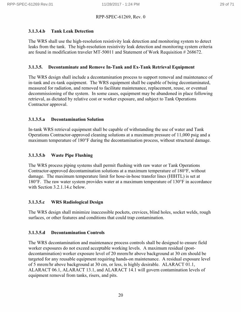
3.1.3.4.b Tank Leak Detection
The WRS shall use the high-resolution resistivity leak detection and monitoring system to detect leaks from the tank. The high-resolution resistivity leak detection and monitoring system criteria are found in modification traveler MT-50011 and Statement of Work Requisition # 268672.
3.1.3.5. Decontaminate and Remove In-Tank and Ex-Tank Retrieval Equipment
The WRS design shall include a decontamination process to support removal and maintenance of in-tank and ex-tank equipment. The WRS equipment shall be capable of being decontaminated, measured for radiation, and removed to facilitate maintenance, replacement, reuse, or eventual decommissioning of the system. In some cases, equipment may be abandoned in place following retrieval, as dictated by relative cost or worker exposure, and subject to Tank Operations Contractor approval.
3.1.3.5.a Decontamination Solution
In-tank WRS retrieval equipment shall be capable of withstanding the use of water and Tank Operations Contractor-approved cleaning solutions at a maximum pressure of 11,000 psig and a maximum temperature of 180°F during the decontamination process, without structural damage.
3.1.3.5.b Waste Pipe Flushing
The WRS process piping systems shall permit flushing with raw water or Tank Operations Contractor-approved decontamination solutions at a maximum temperature of 180°F, without damage. The maximum temperature limit for hose-in-hose transfer lines (HIHTL) is set at 180°F. The raw water system provides water at a maximum temperature of 130°F in accordance with Section 3.2.1.14.c below.
3.1.3.5.c WRS Radiological Design
The WRS design shall minimize inaccessible pockets, crevices, blind holes, socket welds, rough surfaces, or other features and conditions that could trap contamination.
3.1.3.5.d Decontamination Controls
The WRS decontamination and maintenance process controls shall be designed to ensure field worker exposures do not exceed acceptable working levels. A maximum residual (post-decontamination) worker exposure level of 20 mrem/hr above background at 30 cm should be targeted for any reusable equipment requiring hands-on maintenance. A residual exposure level of 5 mrem/hr above background at 30 cm, or less, is highly desirable. ALARACT 01.1, ALARACT 06.1, ALARACT 13.1, and ALARACT 14.1 will govern contamination levels of equipment removal from tanks, risers, and pits.
RPP-SPEC-61269 Rev.01 11/28/2017 - 1:24 PM 29 of 71

RPP-SPEC-61269, Rev. 0
21
3.1.3.5.e Equipment Disposal Considerations
The WRS shall be comprised of disposable equipment, to the extent practical.
3.1.3.5.f Waste Pipe Gravity Drain
The WRS process piping systems should gravity drain and eliminate low spots to minimize freestanding liquids in the process piping as described in 40 CFR 265 and WAC 173-303-640. Siphoning constraints are addressed in Section 3.3.13.1.g. Vacuum breakers shall be included in the design as required to facilitate gravity drainage.
3.1.3.5.g Removability of In-Tank Equipment
The WRS shall be capable of removing in-tank equipment at any time following initial deployment, if needed to facilitate maintenance or replacement of the equipment. The WRS in-tank equipment shall be retrievable from the tank in the event of failure.
3.1.3.6. Distribute Utilities to the WRS (241-A Tank Farm)
The WRS shall control and distribute utilities within the 241-A Tank Farm for use during WRS operations and maintenance. Control and distribution includes electrical power transformation, and the control, distribution, and protection of electrical power, raw water, and service air sources.
3.1.3.6.a Electrical Power Transformation
The WRS shall transform, as necessary, the electrical power available to the WRS, as specified in Sections 3.2.1 and 3.2.5, into 480 VAC, 3-phase, and 120/240 VAC, 1-phase electrical power as needed for WRS loads.
3.1.3.6.b Electrical Power Distribution
The WRS shall distribute and provide 480 VAC power to the 241-A Tank Farm WRS subsystems. Distribution consists of routing 480 VAC, and other voltages as needed, to power WRS loads, as determined by design, such as retrieval and pumping equipment, ventilation equipment (if active ventilation is used), local transformer(s) and power center(s), heat trace, climate control, lighting, instrumentation, and controls. Loading of facility electrical components shall be in accordance with the NESC. The electrical power needs for the WRS shall be determined during design, and loads shall be identified and evaluated to verify the adequacy of the electrical power distribution system. Supply or upgrade utility power systems in compliance with the NESC, as required. Electric utility systems upgrades must be approved bythe Mission Support Alliance electrical utilities group.
RPP-SPEC-61269 Rev.01 11/28/2017 - 1:24 PM 30 of 71
RPP-SPEC-61269, Rev. 0
22
3.1.3.6.c Raw Water Distribution
The WRS shall distribute hot and cold raw water specified in Section 3.2.2 to the WRS at various locations as stipulated during design.
The water system shall be designed to supply hot water at a temperature of 130°F or cold (non-heated) water at 100 gpm concurrently to any two tank WRSs in 241-A Tank Farm or an adjacent tank farm or one tank WRS in 241-A Tank Farm and one tank in an adjacent tank farm.
The maximum capacity of the hot water system shall be no less than 200 gpm.
The maximum capacity of the cold water system shall be no less than 200 gpm.
A hot water interlock shall be provided on the hot water system to protect the safety-significant primary piping system from exceeding 180°F.
For a sluicing WRS, hot and cold water flow rates at the individual sluicers installed at the tanks should be variable from 0 to 100 gpm during either batch processing or continuous pumping.
The system shall be capable of delivering 0 to 100 gpm hot water to one of the WRSs while providing cold water at a flow rate of 0 to 100 gpm to a WRS located at another tank.
During periods of in-line dilution, the available hot or cold water flow to the WRS(100 gpm) may be reduced by the flow rate used for in-line dilution (5-30 gpm).
The water supply to the high pressure water system shall be cold (ambient) temperature.
3.1.3.7. Distribute Utilities to the WRS (Receiving DST)
The WRS shall distribute electricity as required within the receiving DST Farm for consumption during WRS operations and maintenance. Utility distribution includes control, monitoring, distribution, and protection of electrical power sources.
3.1.3.7.a Electrical Power Distribution
The WRS shall distribute and protect power from available sources to WRS instrumentation and control loads in the receiving DST Farm. The additional loads shall be evaluated to verify the adequacy of the electrical power distribution system to support the SST waste retrieval. Modifications to the DST electrical power distribution system shall be in accordance with NFPA 70.
RPP-SPEC-61269 Rev.01 11/28/2017 - 1:24 PM 31 of 71
RPP-SPEC-61269, Rev. 0
23
3.2 System Interfaces and Interface Performance Requirements
The WRS must interface with new and existing utilities and infrastructure systems. An interface arrow diagram, which identifies all of the significant interfaces, is provided in Figure 3-1.
The utilities described in the following subsections are currently available at the 241-A Tank Farm and the receiving DST.
3.2.1 SST Electrical Power System
The SST Electrical Power System interface is at the secondary side of the A241-EDS-XFRM-001 transformer.
3.2.1.a. SST Electrical Power System Performance Requirement
Transformed electrical power capacity in the 241-A Tank Farm is 1000 kVA of 3-phase power at 480/277 VAC. Electrical power needs and availability for the WRS shall be determined during design.
3.2.2 SST Raw Water System
Raw water for the 241-A Tank retrievals is provided at the 241-A-285 Air and Water Service Building.
RPP-SPEC-61269 Rev.01 11/28/2017 - 1:24 PM 32 of 71

RP
P-S
PE
C-61269, R
ev. 0
24
Figure 3-1. Waste Retrieval System – Major Subsystems and Interfaces.
RPP-SPEC-61269 Rev.01 11/28/2017 - 1:24 PM 33 of 71

RPP-SPEC-61269, Rev. 0
25
3.2.2.1. SST Hot Water System
Hot water is provided north of 241-A Tank Farm at the splitter manifold. There are two interface points: valves A241-RW-V-088 and A241-RW-V-089.
3.2.2.1.a SST Hot Water System Performance Requirement
Hot water is available at the splitter manifold. The hot water design conditions are 135 gpm of 250 psig water at 180F. The hot water operating conditions are 135 gpm of 165 psig water at temperatures from ambient to 130F. The hot water system shall be designed such that transfer system maximum design temperatures cannot be exceeded. Water needs for the WRS shall be determined during design.
3.2.2.1.b SST Hot Water Safety Instrumented System Performance Requirement
The hot water safety instrumented system interlocks shall be incorporated into the WRS design.
3.2.2.2. SST Cold Water System
Cold water is provided north of 241-A Tank Farm at the splitter manifold. There is one interface point, valve A241-RW-V-090.
3.2.2.2.a SST Cold Water System Performance Requirement
Cold water is available at the splitter manifold. The cold water design conditions are 55 gpm of 150 psig water at between 40 and 180F. The cold water operating conditions are 55 gpm of 120 psig water at 40 to 100F. Water needs for the WRS shall be determined during design.
3.2.3 SST Service Air System (East Area)
Service air is provided at the 241-A-285 Air and Water Service Building. There are two interface points: hose connections A285-PA-HC-014 and A285-PA-HC-018.
3.2.3.a. SST Service Air System (East Area) Performance Requirement
Service air is available at the 241-A-285 building wall. The service air design conditions are 150 psig air at 150F. The service air nominal conditions are 100 psig air at less than 150F. Service air needs for the WRS shall be determined during design.
RPP-SPEC-61269 Rev.01 11/28/2017 - 1:24 PM 34 of 71
RPP-SPEC-61269, Rev. 0
26
3.2.4 SST Chemical System
Caustic soda (sodium hydroxide) and oxalic acid are available in various molarities via tanker truck and may be introduced into the tank environment by means of a dropleg inserted into a tank riser. The truck will be staged at the 241-A-285 building and piped to the splitter manifold north of 241-A Tank Farm. Hoses will be run from the splitter manifold to the tank’s WRS. The interface point is at valve A285-CHEMB-V-740.
3.2.4.a. SST Chemical System Performance Requirement
The WRS shall be compatible with caustic soda having a concentration up to 50% by weight. Oxalic acid may similarly be added and the WRS shall be compatible with exposure to up to 1 Molar solution.
3.2.5 DST Electrical Power Subsystem
Electrical power may be available to the WRS at the receiving DST. A baseline analysis of the 241-AP Tank Farm electrical distribution systems is documented in RPP-8182. Electrical loads associated with RPP-CALC-60505 shall also be considered.
3.2.5.a. DST Electrical Power Subsystem Performance Requirement
Transformed electrical power capacity at the DST receiving tank in 241-AP Tank Farm is 1000 kVA of 3-phase power at 480/277 VAC. Electrical power needs and availability for the WRS shall be determined during design.
3.2.6 DST Confinement Subsystem
The available volume in the receiving DST shall be considered for existing waste from retrieved tank, as well as secondary wastes generated during waste retrieval (e.g., flush water, and water used to assist the retrieval process).
3.2.6.a. DST Confinement Subsystem Performance Requirement
The generation of secondary wastes during waste retrieval shall be minimized.
3.2.7 System Controls Subsystem
The WRS shall accept control signals from local instrumentation, manual (i.e., operator) inputs, or other sources as necessary to effect safe operation of waste transfer as well as shutdown in the event of a potential release.
RPP-SPEC-61269 Rev.01 11/28/2017 - 1:24 PM 35 of 71

RPP-SPEC-61269, Rev. 0
27
3.2.7.a. System Controls Subsystem Performance Requirement
The required control signals will be determined based on design and process control strategy, but as a minimum they shall include:
Transfer line flow rate, Transfer line pressure, Transfer leak detection alarm signals, Receiving DST waste liquid level, Hydraulic power unit oil temperature, Waste transfer structure temperature alarms, Hot water temperatures, Hot water temperature alarms, Tank vapor space pressure (both SST and DST), and Loss of ventilation (both SST and DST).
3.2.8 SST Ventilation Subsystem
The ventilation system for the SST shall provide air exchange (i.e., vapor space dilution) and confinement of radioactive and hazardous gases and particulates during WRS operations. If active ventilation is required, system components may include fans, ducting, air filtration components, a programmable logic controller (PLC), instrumentation to detect, monitor, or sample the release of radioactive particulates, provisions for sampling organic vapors, and associated ancillary equipment. Passive ventilation is provided by a ducted HEPA breather filter that provides a filtered air exchange path from the tank vapor space for atmospheric breathing.
3.2.8.a. SST Ventilation Subsystem Performance Requirement
The required control signals will be determined based on design and process control strategy, but as a minimum they shall include:
The tank ventilation systems will maintain adequate air exchange for proper tank temperature control, removal of accumulated flammable gases, removal of aerosols that may reduce in-tank visibility, and confinement by filtering radioactive particulates. The associated controls are:
o Exhaust air flow rate,o Exhaust air temperature,o HEPA filter differential temperature,o HEPA filter differential pressure, ando Tank vapor space pressure.
The ventilation systems will conduct volatile organic compounds and noxious vapors away from plant workers.
The 241-A Farm ventilation system design requirements are in RPP-SPEC-60378.
RPP-SPEC-61269 Rev.01 11/28/2017 - 1:24 PM 36 of 71

RPP-SPEC-61269, Rev. 0
28
3.2.9 SST Subsystem
To the extent practical, the WRS design shall minimize the need for removal of existing equipment or modifications to the interfacing tanks. Potential interfaces between the WRS and existing tank structures are discussed in this section. Other physical interfaces will be determined and specified as part of the preliminary design.
3.2.9.a. SST Subsystem Performance Requirement
The WRS shall interface with one or more 241-A tank pits and/or risers (vertical pipes that penetrate the tank) located above the tank (H-14-010608, Sheets 1 and 2, H-2-73386, H-2-73387, H-2-73388, Sheets 1 and 2, H-2-73390, H-2-73392, and H-2-73394). A variety of reinforced concrete pits on each tank contain risers that may be used for the installation and operation of the WRS equipment. Other risers located above grade are also available and risers that are below grade may be modified with extension pipes to bring them above grade for use, if required. The WRS may need to interface with existing tank risers that are off vertical, out of round, or have significant inside dimension/outside dimension offsets. The tanks, risers, and pits elevations require case-by-case evaluation to determine the “as-found” conditions.
3.2.10 DST Subsystem
To the extent practical, the WRS design shall minimize the need for removal of existing equipment or modifications to the interfacing tanks. Potential interfaces between the WRS and existing tank structures are discussed in this section. Other physical interfaces will be determined and specified as part of the preliminary design.
3.2.10.a. DST Subsystem Performance Requirement
The WRS shall interface with the existing risers at the riser flange on the receiving DST. Associated systems, such as the DST primary ventilation, shall be considered for interfaces or potential impacts as well. The receiving DST designated for 241-A Tank Farm is 241-AP-101. The riser configuration drawing for 241-AP-101 is H-14-010503, Sheet 1.
3.3 Design Requirements
The WRS shall be designed in accordance with the requirements of the following subsections. Note that the use of non-compliant existing portions of the SST System is subject to the RCRA negotiation and approval process and relevant agreement pursuant to the HFFACO.
RPP-SPEC-61269 Rev.01 11/28/2017 - 1:24 PM 37 of 71
RPP-SPEC-61269, Rev. 0
29
3.3.1 Safety
The WRS shall be designed to protect workers, the public, the environment, and equipment in accordance with the requirements of this section and with the principles and procedures of the TFC-PLN-41.
3.3.1.1. Personnel Safety
Personnel shall be protected from work-place hazards in accordance with the requirements of this section.
3.3.1.1.a Occupational Radiological Protection
The WRS shall be designed to protect workers from occupational radiation exposure in accordance with the requirements contained in HNF-5183, and shall be designed to keep personnel exposure as low as reasonably achievable (ALARA), including design provisions to facilitate decontamination during the operational period per DOE O 420.1C.
3.3.1.1.b Occupational Safety and Health
The WRS shall be designed for safe installation, operation, and maintenance in accordance with applicable requirements of 29 CFR 1910 and 29 CFR 1926.
3.3.1.1.c Hazards Identification
All hazards and potential safety issues associated with installation, operation, and maintenance of the WRS shall be identified and documented, including but not limited to chemical, thermal, nuclear, pneumatic, hydraulic, mechanical, and electrical hazards.
3.3.1.1.d Excavation
All excavations will be performed in accordance with WRPS procedures and DOE-0344.
3.3.1.2. Protection of Plant and Equipment
All WRS subsystems shall be designed to avoid damage to other components.
3.3.1.2.a Vibration
WRS transfer pumps shall meet the design, fabrication, and testing requirements contained in API 610 or other applicable standard. The resonant frequencies particular to the pump installation shall be analyzed, as applicable, and design features added to preclude damage to the
RPP-SPEC-61269 Rev.01 11/28/2017 - 1:24 PM 38 of 71
RPP-SPEC-61269, Rev. 0
30
tank structure from resonant frequencies and to eliminate the harmonics in the pump’s normal operating range.
3.3.1.2.b WRS Structural Integrity and Design
The WRS shall be designed to ensure proper structural strength, compatibility with the waste, and protection against corrosion in accordance with 40 CFR 265.192 and WAC 173-303-640(3).
3.3.1.2.c Fire Protection
The WRS shall meet fire protection design requirements as defined in TFC-ESHQ-FP-STD-02, DOE-STD-1066-2016, and DOE O 420.1C.
3.3.1.2.d DST Design Limits
The WRS shall not adversely affect the function of the DST System or exceed the DST design and operational limits specified in HNF-SD-WM-TRD-007 and OSD-T-151-00007.
3.3.1.3. Protection of the Environment
The WRS shall be designed to protect the public and environment in accordance with the requirements identified in RPP-16922 and the requirements of this section.
3.3.1.3.a Secondary Containment and Leak Detection
The WRS shall incorporate secondary containment and leak-detection design features in accordance with 40 CFR 265.193 and WAC 173-303-640(4). If HIHTLs are used, the WRS shall comply with RPP-12711.
3.3.1.3.b Transfer Pits and Process Skids
Encasement and secondary containment features associated with WRS transfer pits (new or modifications) and process skids or containers shall be designed to completely drain, to the extent feasible, any freestanding liquids resulting from leaks or spills. Encasement or secondary containment drain lines shall comply with the following:
Lines shall drain with no holdup, or allow removal of held-up waste within 24 hours or in as timely a manner as possible to prevent harm to human health and the environment.
Additional requirements in WAC 173-303-640, as applicable.
RPP-SPEC-61269 Rev.01 11/28/2017 - 1:24 PM 39 of 71
RPP-SPEC-61269, Rev. 0
31
3.3.1.3.c Spill Prevention and Controls
The new and modified portions of the WRS shall incorporate spill prevention and control design features in accordance with 40 CFR 265.193 and WAC 173-303-640(5) with the most stringent requirement taking precedence.
3.3.1.3.d Non-Radioactive Airborne Emissions
The WRS shall be designed to comply with the non-radioactive airborne emissions requirements contained in WAC 173-400, WAC 173-460, TFC-ESHQ-ENV-STD-04, and Order DE05NWP-002. Non-radioactive airborne emissions from the 241-A Tank Farm, other tank farms, and other Hanford Site major facilities shall be considered when designing the system to be compliant with WAC 173-400 and WAC 173-460.
3.3.1.3.e Radioactive Airborne Emissions
The WRS shall be designed to comply with radioactive airborne emissions requirements contained in TFC-ESHQ-ENV-STD-03, AIR-12-331, and AIR-12-307.
3.3.1.3.f Radiation Protection of the Public and Environment
The system shall be designed in accordance with the radiation release limits specified in 10 CFR 835 and WAC 246-247.
3.3.1.4. Nuclear Control
The risks from abnormal events and postulated accidents that can result in the uncontrolled release of radioactive or hazardous material during retrieval of waste from the SST are related to the retrieval concept and design details. The nuclear safety requirements are determined by the hazardous conditions associated with deployment and operation of the WRS. Nuclear safety requirements shall be evaluated in accordance with 10 CFR 830. The applicable controls are found in the technical safety requirements contained in HNF-SD-WM-TSR-006 and corresponding sections of HNF-IP-1266.
3.3.2 Environmental Conditions
3.3.2.1. Natural Environment
This section defines the natural conditions (e.g., weather) under which the WRS shall be capable of operating.
RPP-SPEC-61269 Rev.01 11/28/2017 - 1:24 PM 40 of 71

RPP-SPEC-61269, Rev. 0
32
3.3.2.1.a Natural Environmental Conditions
The WRS shall be designed for outdoor installation and use, with above-grade components designed per TFC-ENG-STD-02.
3.3.2.1.b Ultraviolet Resistant Components
The WRS components (e.g., elastomers) subjected to the ex-tank environment shall be resistant to, and continue to function as designed while exposed to, ultraviolet solar radiation for a minimum of three years before requiring replacement.
3.3.2.1.c Design Loads
The WRS shall be designed to withstand the natural phenomena hazard loads, dead loads, and other loads as specified in TFC-ENG-STD-06 and applicable codes. The WRS shall also be designed for loads associated with hoisting and rigging as identified in Section 3.5.6.
3.3.2.2. Induced Environment
The WRS shall be designed for operating in the in-tank environmental conditions described in the following subsections.
3.3.2.2.a In-Tank Radiological Exposure Rates
The maximum in-tank radiological exposure rates for SSTs are provided in Table 3-3.
Table 3-3. In-Tank Radiological Exposure Rates.
Tank
Total Beta Submersion
Exposure Rate (Rad/hr)
Total Beta Surface
Exposure Rate
(Rad/hr)
Gamma Submersion
Exposure Rate (Rad/hr)
Gamma 1 Foot Above
Surface Exposure Rate
(Rad/hr)
Gamma 10 Feet Above Surface Exposure Rate
(Rad/hr)
241-A-101 183 91.5 190 117 43.8
241-A-102 624 312 182 111 41.6
241-A-103 175 87.5 158 96.8 36.4
241-A-104 26,200 13,100 394 229 86.3
241-A-105 26,600 13,300 555 335 126
241-A-106 11,100 5,550 213 130 49
Note: Data from RPP-CALC-57060, Table 14.
RPP-SPEC-61269 Rev.01 11/28/2017 - 1:24 PM 41 of 71
RPP-SPEC-61269, Rev. 0
33
3.3.2.2.b In-Tank Humidity Range
The in-tank relative humidity ranges from 5% to 100%.
3.3.2.2.c Waste pH Range
The waste pH is 10 or greater for normal operations. In addition, equipment wetted by the waste solution shall be compatible with exposure to oxalic acid (up to 1.0 molar).
3.3.2.2.d Temperature Range
The bulk waste temperature range is shown in Table 3-1 for SSTs. Vapor space air temperatures may experience a wider range because of the influx of ambient (ex-tank) air due to active or passive ventilation.
3.3.2.2.e Vapor Space Pressure
See Section 3.1.1.3 for the required vapor space pressure. (Note that retrieval operation will not continue at positive tank pressures, but the system may be subjected to them.)
3.3.2.2.f Flammable Gas
The flammable gases of concern are hydrogen, ammonia, and methane. Equipment must satisfy HNF-SD-WM-TSR-006, SAC 5.8.2, “Flammable Gas Control for WASTE-INTRUDING EQUIPMENT,” requirements and Tank Operations Contractor Flammable Gas Equipment Advisory Board review.
3.3.2.2.g Organics
Organics present in the liquid waste should be considered in the design. The organic compounds and quantities present are found in the best-basis inventory information in the TWINS database.
3.3.2.2.h Chemical Environment
WRS equipment in contact with the tank waste shall be designed to perform its intended function in the chemical environment in the tank. This environment and its context are described in Appendix B of HNF-SD-WM-SP-012 and the TWINS database. In addition, equipment in contact with tank waste shall be compatible with exposure to oxalic acid up to 1.0 Molar.
RPP-SPEC-61269 Rev.01 11/28/2017 - 1:24 PM 42 of 71
RPP-SPEC-61269, Rev. 0
34
3.3.2.3. Environment Due to Accidents and Unplanned Events
3.3.2.3.a Tank Exhauster Stack Continuous Air Monitor (CAM) Interlock
If active ventilation is required during waste retrieval, the WRS shall include a compliant (reference Section 3.3.15) record sampler and CAM stack interlock, or other feature to support shutdown of the ventilation system fan and flow through the stack in the event of a HEPA filter failure. The 241-A Tank Farm ventilation system is the subject of a separate specification, RPP-SPEC-60378.
3.3.3 Human Performance/Human Factors Engineering
The WRS shall be designed for ease of operation and to comply with general criteria given in TFC-PLN-09, TFC-ENG-DESIGN-D-29, and TFC-ENG-STD-01.
3.3.3.1. Lighting
The WRS shall provide lighting for interior and exterior WRS work areas, as appropriate, in accordance with TFC-ESHQ-IH-STD-13. The WRS will provide sufficient in-tank lighting to support remote operation using camera systems for viewing the retrieval process and in-tank activities.
3.3.4 Personnel and Training
The WRS shall be designed for operation and maintenance by qualified personnel trained to the levels described in TFC-BSM-TQ-STD-02, TFC-BSM-TQ-STD-10, and TFC-BSM-TQ-STD-17.
3.3.5 Control System
3.3.5.1. Control and Monitor Waste Retrieval and Transfer Processes
The WRS shall monitor and control the process for retrieving waste from the SST, including waste retrieval process parameters critical to safety, operation, and process control. Parametersmay include, as applicable, waste transfer line pressures, flow rates, environmental safety parameters (e.g., leak detection), and equipment parameters (e.g., transfer pump speed and motor amperage). The control and monitoring of the waste retrieval process are integral to the control of in-tank and waste parameters discussed in Sections 3.1.1 through 3.1.3, including subsections thereof.
RPP-SPEC-61269 Rev.01 11/28/2017 - 1:24 PM 43 of 71

RPP-SPEC-61269, Rev. 0
35
3.3.5.1.a Remote Operation
The WRS shall be operated and monitored either locally (i.e., manually) or from a control station outside the 241-A Tank Farm fence, approximately 250 to 600 feet from the SST. Manually operated valves may be included as needed in the WRS design. Primary system controls within the tank farm shall be readily accessible and support the modularity of design.
3.3.5.1.b Monitor In-Tank Operations
The WRS shall be capable of providing real-time video monitoring of in-tank waste retrievaloperations.
3.3.5.1.c Monitor Waste Retrieval and Transfer Process
The WRS shall be capable of quantifying the total amount of waste retrieved and transferred to the receiving DST for purposes of supporting material balance calculations, in accordance with HNF-IP-1266, Section 7.2, “Material Balance Monitoring.”
3.3.5.1.d WRS Emergency Stop Feature
The WRS shall have an emergency stop feature located in the associated control trailer that will shut down the waste retrieval transfer pump.
3.3.5.1.e Locking Features
The WRS transfer pump, sluicer and other WRS equipment or systems with hazardous energy sources shall have locking features that remove and secure motive power, without having to open the electrical cabinets, to support compliance with HNF-IP-1266, Appendix 5.B, “Administrative Lock Controls,” 29 CFR 1910.147, and DOE-0336.
Active ventilation, if used, shall also have locking features to enable removing and securing motive power to prevent inadvertently exceeding Operating Specification Document (OSD) limits. Implementation of this control is addressed in a separate 241-A Tank Farm ventilation system specification, RPP-SPEC-60378.
Administration of locks on WRS transfer pumps and other equipment will be the responsibility of Tank Farm Operations. Key switches shall be incorporated into the design to facilitate lockout where possible.
3.3.5.1.f WRS Process Parameters
The WRS shall have the capability to monitor the following parameters:
WRS Waste Transfer Line Subsystem transfer slurry pipeline flow rate,
RPP-SPEC-61269 Rev.01 11/28/2017 - 1:24 PM 44 of 71

RPP-SPEC-61269, Rev. 0
36
WRS Waste Transfer Line Subsystem transfer slurry pipeline totalized flow, Waste transfer pipeline pressures, Waste transfer structure temperature alarms, Waste density in the slurry pipeline, Waste temperature in the slurry pipeline, Waste level in the receiving DST, Low vacuum (high pressure) in the receiving DST, Waste temperatures on active thermocouples in the receiving DST, Tank vapor space pressure in the SST during retrieval, Ventilation exhaust stack CAM alarm for the SST, Ventilation exhaust record sample alarm for the SST, Ventilation exhaust stack flow rate, HEPA filter differential temperature, HEPA filter differential pressure, and Leak detection alarms.
All set points shall be established with ranges that allow maximum flexibility of operation as allowed by requirements. Set points for safety-significant structures, systems, and components (SSC) will be developed in accordance with TFC-ENG-STD-14 for instrumentation used to verify HNF-SD-WM-TSR-006 compliance.
3.3.5.1.g Control System Software
PLCs and human-machine interface (HMI), if used, shall have the necessary software to enable operator communication and equipment interfaces with the WRS instrumentation to support the process control and operational needs of the WRS. Software shall be acquired and developed in accordance with TFC-BSM-IRM_HS-C-01 and associated procedures. Graphic display and color coding will be developed in accordance with TFC-ENG-STD-23. Alarm and annunciator panel design shall comply with TFC-ENG-STD-40. Process control software being designed or acquired for process control systems, including smart instrumentation and equipment, shall be developed in accordance with TFC-ENG-DESIGN-D-12.1 and TFC-ENG-DESIGN-P-12.
3.3.6 System Design Life
3.3.6.1. Design Life
The WRS should have the reliability and availability to support up to a 16-year retrieval schedule, depending on the component.
3.3.6.2. Operational Life
The WRS in-tank equipment, which supports a specific tank’s retrieval, should be available for up to one year during installation, acceptance testing, and operational readiness verification,
RPP-SPEC-61269 Rev.01 11/28/2017 - 1:24 PM 45 of 71

RPP-SPEC-61269, Rev. 0
37
followed by a one-year retrieval campaign to complete retrieval of the waste from the SST. The WRS equipment, which supports retrieval of multiple tanks, should be available for up to 1 year during installation, acceptance testing, and operational readiness verification, followed by a 15-year retrieval campaign to complete retrieval of the waste from the 241-A Tank Farm.
3.3.6.3. In-Tank and In-Pit Component Design Life
In-tank, in-pit, and critical components of the WRS that cannot be repaired or replaced remotely shall achieve a minimum of two years of operation between failures with no maintenance during the two-year period.
3.3.6.4. Above-Grade Component Design Life
The WRS above-grade components and systems, which support a specific tank’s retrieval, shall have a minimum design life of two years with up to five years preferred. The WRS equipment,which supports retrieval of multiple tanks, shall have a minimum design life of 5 years with up to 16 years preferred.
3.3.7 Materials
3.3.7.1. Materials Restrictions
The WRS shall not introduce any material that will prohibit waste transfer from the SST to the receiving DST in accordance with HNF-SD-WM-OCD-015. Non-metallic materials that are in contact with waste shall comply with the requirements of TFC-ENG-STD-34.
3.3.7.2. Welding
Welding connections shall be designed and specified in accordance with the appropriate consensus code or standard, for example but not limited to ASME B31.1, ASME B31.3, ASME B31.9, and ASME B&PVC, Section IX. Requirements for welding and welder certifications for systems requiring compliance with ASME or AWS are specified below.
3.3.7.2.a Fabrication Weld Standards
Fabrication welds on WRS containment boundaries, lifting devices, structural components, and at other critical locations shall be performed to the requirements of applicable ASME and AWS standards.
RPP-SPEC-61269 Rev.01 11/28/2017 - 1:24 PM 46 of 71

RPP-SPEC-61269, Rev. 0
38
3.3.7.2.b In-Process Inspection
In-process inspection may not be used in-lieu of other nondestructive examination (NDE) for welds. An exception to this is if weld geometry precludes the use of NDE.
3.3.7.2.c Welder Certification
Welding shall be performed by welders certified in accordance with AWS D1.1, AWS D1.3, AWS D1.6, ASME B&PVC, Section IX, or other consensus code or standard as appropriate.
3.3.7.3. Toxic Products and Formulations
The WRS design, installation, maintenance, and operation shall comply with WRPS Environment, Health, Safety, and Quality organization guidance, regarding toxic or regulated substance management, in particular but not limited to the materials identified in the following subsections.
3.3.7.3.a Lead
Lead shall not be used in the WRS unless the lead is fully encapsulated and identified with a permanent tag.
3.3.7.3.b Toxic Substances
Materials listed in TSCA, including polychlorinated biphenyls, shall not be incorporated into the WRS design.
3.3.7.3.c Hydraulic Fluid
Hydraulic fluid used in in-tank equipment, and in secondary containment structures with leak detection, shall be approved by the Tank Operations Contractor.
3.3.8 Security
There are no specific security functions or requirements associated with the WRS.
3.3.9 Decontamination and Decommissioning
The WRS shall be designed for ease of decontamination during operation and for decommissioning at the end of system life in accordance with DOE O 420.1C. Consideration should be made for draining of hydraulic fluid and other liquids from cavity regions of
RPP-SPEC-61269 Rev.01 11/28/2017 - 1:24 PM 47 of 71

RPP-SPEC-61269, Rev. 0
39
potentially contaminated equipment. Additional requirements related to system decontamination to support maintenance apply; see also Section 3.1.3.5.
3.3.10 Electromagnetic Radiation
The WRS shall comply with electromagnetic radiation emission requirements set forth in HNF-2962, as applicable, to include, as a minimum, the following standards:
Equipment Installation and Wiring Practices, and Radio Frequency Interference Susceptibility.
3.3.11 Nameplate and Product Marking
The WRS shall label new equipment and/or modifications to existing equipment in a standardized format in accordance with the tank farm labeling program as specified in TFC-ENG-FACSUP-C-23, TFC-ENG-STD-12, and applicable drawings.
3.3.12 Electrical Component Requirements
3.3.12.1. Electrical and Instrument and Control Equipment
The requirements described in the following subsections apply to WRS electrical and instrumentation & controls equipment.
3.3.12.1.a Equipment Listing
All electrical equipment used in the WRS design shall be listed, or labeled, by a nationally recognized testing laboratory (NRTL) such as UL. Exceptions are addressed in DOE-0359.
3.3.12.1.b Electrical Cabinet Design
Cabinets containing motor control systems shall be designed, constructed, and labeled to the UL 508A standard. Cabinets that contain two or more active components, including related control devices, shall also be designed, constructed, and labeled to the UL 508A standard. Non-UL 508A cabinets shall be part of an NRTL-labeled system or comply with other options detailed in TFC-ENG-STD-41. Indoor and outdoor electrical equipment enclosures shall be rated for their intended environment.
3.3.12.1.c Locking Features
New electrical systems and modifications to existing electrical system shall include a lockable disconnecting means capable of being locked out in the open position as
RPP-SPEC-61269 Rev.01 11/28/2017 - 1:24 PM 48 of 71
RPP-SPEC-61269, Rev. 0
40
required by Section 110.25 of the NFPA 70. The provisions for locking shall remain in place with or without the lock installed.
New electrical systems and major modifications to existing system equipment shall be designed to provide the capability of being locked out to support compliance with HNF-IP-1266, Appendix 5.B, 29 CFR 1910.147, and DOE-0336.
3.3.12.1.d Pump Starters
The pump starters shall include uniquely keyed key-switches to minimize the need to install administrative locks.
3.3.12.1.e Electrical Equipment
All electrical equipment and installation shall be inspected for NFPA 70 compliance.
3.3.12.1.f Electrical Raceways
When used, electrical raceway systems design, installation and material requirements shall be in compliance with TFC-ENG-STD-15.
3.3.13 Mechanical Component Requirements
3.3.13.1. Process Piping and Pressure Vessels
Process piping for the WRS shall meet the criteria identified in the following subsections.
3.3.13.1.a Process Piping Code
WRS process piping shall conform to the requirements of ASME B31.3 for “Normal Fluid Service.” Additionally, process piping shall conform to any relevant piping requirements specified within TFC-ENG-STD-22.
3.3.13.1.b Flexible Piping Code
If used, HIHTL shall comply with the requirements of RPP-12711, RPP-14859, TFC-ENG-STD-21, and OSD-T-151-00010.
3.3.13.1.c Temporary Over-Ground Waste Transfer Lines
Temporary over-ground waste transfer lines (typically HIHTL), if used, shall comply with the requirements of RPP-12711, RPP-14859, and TFC-ENG-STD-21.
RPP-SPEC-61269 Rev.01 11/28/2017 - 1:24 PM 49 of 71

RPP-SPEC-61269, Rev. 0
41
3.3.13.1.d Pressure Vessels and Vacuum Systems
If the process piping includes pressure vessels or vacuum systems, the vessels shall conform to applicable requirements of ASME B&PVC, Section VIII.
3.3.13.1.e Jumpers and Valves
If used, in-pit jumpers shall utilize Hanford standard PUREX connectors or other appropriate connections to facilitate installation and minimize personnel exposure. In-pit jumpers shall include features that allow the introduction of water after installation to verify that the connectors are leak-tight. Jumpers and valves will be designed in accordance with TFC-ENG-STD-22.
3.3.13.1.f Process Piping Temperature
The WRS process piping and hoses shall be designed to handle fluids with a maximum temperature of 180F.
3.3.13.1.g Siphoning Constraints
WRS process piping shall be designed to preclude radioactive waste from being siphoned from the receiving DST to the SST.
3.3.13.1.h Flush Connections
WRS waste transfer lines shall be designed for temporary connection to compressed air and raw water at the SST end of the transfer system for flushing at a rate suitable for removing settled solids from the transfer line.
3.3.13.2. Transfer Pumps
The WRS transfer pump design and installation shall be in compliance with TFC-ENG-STD-25.
3.3.13.2.a Transfer Pump Design Characteristics
The WRS transfer pump design shall include the following:
The WRS transfer pump design shall use the fluid design temperature identified in Section 3.1.3.2.b.
The maximum viscosity of the waste to be pumped is 40 cP.
The maximum density of the waste to be pumped is 1.52.
RPP-SPEC-61269 Rev.01 11/28/2017 - 1:24 PM 50 of 71

RPP-SPEC-61269, Rev. 0
42
The maximum percent solids to be pumped is 25%.
The maximum particle size is 3/8 inch.
The WRS transfer pump shall have a minimum draw down level of 1 inch.
The WRS transfer pump shall include an in-line dilution line, which shall introduce diluent directly into the suction of the pump while it is running. The in-line dilution line shall accommodate 0- to 30-gpm dilution water at up to 100 psig at a maximum of 130°F.
3.3.14 Raw Water Component Requirements
The WRS shall have features that preclude contamination of the raw water system and provide protection in accordance with safety basis requirements.
3.3.14.1. Raw Water Piping Codes
The raw water system piping shall conform to the requirements of ASME B31.1, for components with design pressures higher than 350 psig. For components with design pressures that are less than 350 psig, the raw water system piping shall conform to the requirements of ASME B31.9.
3.3.14.2. Raw Water System Protection
Protection of the raw water system shall be provided in accordance with WAC 246-290-490, “Cross Connection Control.”
3.3.14.3. Disconnection from Waste Transfer System
The raw water system shall be isolated from the waste transfer system during waste transfer operations by one of the methods described in the following subsections.
3.3.14.3.a Backflow Prevention
If a backflow preventer is to be used, it shall be approved for use in Washington State.
3.3.14.3.b Isolation Valves
The WRS waste transfer line flushing systems, and other raw water connections physicallyconnected to waste transfer or process piping, shall be protected by two isolation valves, in compliance with HNF-SD-WM-TSR-006, SAC 5.8.6, “Double Valve Isolation.”
RPP-SPEC-61269 Rev.01 11/28/2017 - 1:24 PM 51 of 71

RPP-SPEC-61269, Rev. 0
43
3.3.14.3.c Disconnection
The WRS raw water system contamination protection shall be accomplished by physically disconnecting the water and transfer systems.
3.3.15 Air and Gas Treatment System Design
The WRS ventilation subsystems and connecting ductwork shall be designed in accordance with RPP-SPEC-60378.
3.3.16 Waste Transfer Structures
Pit cover blocks or cover plates used by the WRS shall be designed or configured such that the installed condition can be verified prior to the start of waste retrieval, and periodically thereafter during waste retrieval and transfer. Similarly, doors or hatches on any ex-tank process enclosures housing waste process piping shall be designed such that the installed condition can be verified at any time to comply with HNF-SD-WM-TSR-006, AC 5.9.3, “Waste Transfer –Associated Structure Cover Installation and Door Closure.” The pit cover block and cover plate design shall also address the hoisting and rigging requirements in Section 3.5.6.
3.3.17 Load Limitations
The load limitations identified in the following subsections shall apply to the WRS design.
3.3.17.1. Load on Tank Risers
Allowable riser loads and moments on all 241-A SSTs to be retrieved by the WRS must be analyzed and documented as part of WRS design, based on specific loading information.
3.3.17.2. Allowable Load on Tank Bottom
The bottom surface of the SST may be used to support in-tank retrieval equipment. The maximum load imparted by the WRS shall not exceed the value given by the formula (WHC-SD-W340-ANAL-001):
W = 1,250 x (load area diameter [inch] + 4.25) (lbf)
3.3.17.3. Tank Dome Loading
The WRS shall not exceed the maximum dome loading on existing SSTs and DSTs as specified in TFC-ENG-FACSUP-C-10.
RPP-SPEC-61269 Rev.01 11/28/2017 - 1:24 PM 52 of 71

RPP-SPEC-61269, Rev. 0
44
3.3.17.4. Facility Loads
Loads imparted onto the existing facility and equipment during construction activities shall be considered during design development.
3.3.18 Equipment Removal Component Requirements
A number of components may be needed to support removal of the existing equipment in the tanks. These components include grout boxes for disposal, spray rings for decontamination support, and work platforms.
3.3.18.1. Grout Boxes
The following criteria apply to grout box designs:
The box should be shaped to minimize the grout volume.
The grout box should be shaped at the upper end to accommodate the riser flange and minimize the other end.
The box design should include a minimum of 1-foot of extra length (below the riser flange) in case the component is longer than expected.
The grout box material should be 1/2-inch thick steel.
The design should provide 5 inches of clearance from the edge of the component to the interior side wall of the box.
Analysis should assume that the void space within the bagged component will be filled with grout.
Design should include a spreader beam for lifting the box loaded with the component and grout.
3.3.18.2. Spray Rings
The following criteria apply to spray ring designs:
The spray ring design pressure is 11,000 psig with an operating pressure of 10,000 psig.
The spray ring shall be a low volume system with a nominal demand of 34 gpm.
The spray ring shall be designed for a maximum fluid temperature of 140°F.
The spray ring shall be a split ring design, if requested by Construction.
RPP-SPEC-61269 Rev.01 11/28/2017 - 1:24 PM 53 of 71

RPP-SPEC-61269, Rev. 0
45
The spray ring design should be optimized for highest impact force.
Water filtered to 10 µm is available for use in the spray ring.
The spray ring design shall accommodate various river and equipment diameters.
The spray ring design shall include “baskets” or other means of support for radiation monitoring equipment.
3.3.18.3. Work Platforms
The following criteria apply to work platforms:
In addition to the weight of the lifted equipment and spray ring, a nominal worker and equipment weight of 7,000 lbs shall be included in the applicable analysis.
The work platforms present a hazard to the safety-significant components within the waste transfer pits, and therefore PC-2 seismic loads as specified in TFC-ENG-STD-06 shall be considered in the design.
The work platforms shall be a split design such that the spray rings supported by the platform may surround the equipment being removed, if requested by Construction.
Ports or “windows” shall be provided to permit access for radiation monitoring during equipment removal activities.
3.3.19 In-Farm Camera Requirements
Cameras shall be mounted such that the entire transfer route may be monitored from the control trailer.
3.3.20 Above-Grade Transfer Line Radiation Monitoring Well Requirements
The WRS design shall include radiation monitoring wells for the above-grade transfer lines. The radiation wells should extend below the above grade lines similar to those depicted on H-14-110060, Sheet 14. The radiation wells should be placed at low points and other locations where particulate build-up may be expected. The information from the radiation wells will be used when determining remaining useful life of the above grade transfer lines.
RPP-SPEC-61269 Rev.01 11/28/2017 - 1:24 PM 54 of 71

RPP-SPEC-61269, Rev. 0
46
3.4 System RAMI Requirements
3.4.1 Reliability
Quantitative numbers for the reliability of the various components of the WRS are not available.
WRS component selection shall consider the intended life of the component and its documented performance history in environments similar to the one in which it will be used, to ensure its reliability.
3.4.2 Availability
Quantitative numbers for the availability of the various components of the WRS have not been identified.
The WRS is expected to be available for up to one year during installation, acceptance testing, and operational readiness verification, followed by a one-year waste retrieval campaign for each A-farm tank.
3.4.3 Maintainability
The WRS design shall, to the extent practical, standardize on like-function components to simplify maintenance and spare parts inventories.
3.4.4 Inspectability
The WRS design shall, to the extent practical, provide inspection access ports for the various waste transfer structures.
3.5 System Other Requirements
3.5.1 Infrastructure Requirements
Infrastructure requirements are identified in Sections 3.1.3.6 and 3.1.3.7.
3.5.2 Operating Requirements
The WRS design shall, to the extent practical, allow operation of the components and systems without farm entry during sluicing operations.
RPP-SPEC-61269 Rev.01 11/28/2017 - 1:24 PM 55 of 71
RPP-SPEC-61269, Rev. 0
47
3.5.3 Maintenance Requirements
3.5.3.1. Ease of Maintenance/Modularity of Design
The WRS shall be designed for ease of maintenance and, to the extent practical, be of a modular design for removal, repair, or replacement.
3.5.3.2. Maintenance
Remote, limited, or contact maintenance requirements shall be implemented to be consistent with current regulatory requirements, policies, and procedures. Operation should be remote to minimize exposure and contamination.
3.5.3.2.a Corrective and Preventative Maintenance
Corrective and preventative maintenance shall be performed by Hanford Site Crafts personnel unless special circumstances require specific vendor maintenance support. A vendor service agreement shall be used under these circumstances.
3.5.3.2.b Calibration
The WRS shall be designed to allow periodic calibration.
3.5.3.2.c Cycles, Methods, and Equipment for Calibration
Calibration cycles, methods, and equipment shall be established based on manufacturer’s instructions, component and system reliability, environmental conditions, and site-specific historical data. This information shall be included in equipment lists as required.
3.5.3.2.d After-Installation Calibration
The WRS equipment located inside the SST, DST, or transfer-associated structure shall not require calibration after installation.
3.5.4 Spare Capacity and Interchangeability
3.5.4.1. Flexibility and Expansion
The WRS design shall consider features (e.g., instrumentation, jumpers, and manifolds) that allow operational flexibility to transfer tank contents from the SST to any 200 East Area DST.
RPP-SPEC-61269 Rev.01 11/28/2017 - 1:24 PM 56 of 71
RPP-SPEC-61269, Rev. 0
48
The WRS design shall consider the use and layout of components that allow for their use on additional SST retrievals (e.g., control systems, HIHTLs, etc.).
3.5.4.2. Spares
The minimum number of spares needed for like components shall be determined during design of the WRS and shall be based on the mean time between failures, vendor recommendations, procurement lead times, operational strategy, safety classification, operational experience from previous SST retrievals, and the number of like components installed. These requirements shall be documented in a project spare parts list.
3.5.4.3. Computer Resource Reserve Capacity
There are no computer resource reserve capacity functions or requirements associated with the WRS.
3.5.4.4. Interchangeability
The WRS design shall standardize like-function components, to the extent practical, to simplify maintenance and spare parts inventories. The design shall incorporate existing tank farm equipment and components to the extent feasible.
3.5.5 Transportability
3.5.5.1. Transportability
The WRS shall be designed for ease of equipment transport, installation in the field, and dismantling. The WRS shall be modular to the extent practical, and shall be designed to be transportable using existing Hanford Site rigging and transport equipment.
3.5.5.2. Preparation for Delivery
SSCs may require special packaging to protect them from corrosion, contamination, physical damage, or any effect that would lower the quality of the items or cause them to deteriorate during shipping and handling. Packaging, receipt, and storage requirements will depend on the classification level of the items. The storage classification levels shown in ASME NQA-1, Subpart 2.2, Section 3-2, shall be used for WRS SSCs.
All WRS equipment shall be shipped in an orientation ready for lifting. Additional handling of the equipment to position it for lifting is not acceptable. Necessary lifting devices, as well as lifting and transport instructions and limitations, shall be provided. Lower level specifications (e.g., procurement specifications) will establish additional specific packaging requirements.
RPP-SPEC-61269 Rev.01 11/28/2017 - 1:24 PM 57 of 71

RPP-SPEC-61269, Rev. 0
49
Other equipment shall be packaged to prevent damage from normal condition experienced during handling and transport.
3.5.6 Hoisting and Rigging Requirements
DOE-RL-92-36, RPP-8360, and TFC-ENG-STD-06 shall be used where applicable to the design of the WRS and equipment, including the removal of existing equipment and structures.
3.5.6.1. Hoisting Design and Test Reviews
Hoisting and rigging device or equipment designs, tests, and reports shall be submitted to the Tank Operations Contractor for safety evaluation and approval during design review. Lift points are to be designed in accordance with TFC-ENG-FACSUP-C-25 and RPP-8360, or other appropriate design standards. Lifting design shall include load conditions for lifting the load and rotation of the load from horizontal to vertical if appropriate. The suspended assembly shall hang to within 2 in. of true vertical end to end. The design shall also address lifting attachments, all associated lifting and rigging equipment, and an area free of sharp edges or corners on the lower end of the equipment for attachment of a choke hitch during equipment removal.
3.5.6.2. Built-in Hoisting Equipment
If used, any built-in hoisting equipment that is part of the WRS shall be evaluated, during design, by the Tank Operations Contractor Hoisting and Rigging Authority for compliance with applicable requirements of DOE-RL-92-36, TFC-ENG-FACSUP-C-25, RPP-8360, and WRPS procedures.
3.5.6.3. Below-the-Hook Lifting Device Requirements
Structural and mechanical below-the-hook lifting devices, as defined by ASME B30.20, shall conform to the requirements of ASME B30.20. Documentation and calculations shall be submitted as evidence that the appropriate welding codes, qualified welders, NDE procedures, testing requirements, etc., have been used. Calculations will be required for the design of all hoisting and rigging equipment and lifting points (of those regulated by ASME B30.20). Below-the-hook lifting devices shall be load tested to 125% of the rated load.
3.5.6.4. Critical Welds
All critical welds on the WRS shall be identified in the design media. For the purpose of this requirement, critical welds are defined as those welds whose failure could result in loss of load or loss of load control. All critical welds on lifting devices shall be full-penetration welds, if possible, and shall be verified by a Tank Operations Contractor approved NDE expert.
RPP-SPEC-61269 Rev.01 11/28/2017 - 1:24 PM 58 of 71

RPP-SPEC-61269, Rev. 0
50
3.5.6.5. Below-the-Hook Lifting Device Markings
Structural and mechanical below-the-hook lifting devices shall be provided with labeling and markings per DOE-RL-92-36 and ASME B30.20.
3.5.6.6. Lifting Attachments and Equipment Design
The lifting attachment(s) on the equipment (lifting eyes, lugs, ears, etc.) and the lifted item shall be designed in accordance with RPP-8360 except ASME BTH-1 should be used to verify lifting lugs versus pin diameter design. The design shall consider equipment orientation, i.e., horizontal to vertical.
3.5.7 Qualification Tests
Qualification testing has not been identified for the expected system designs. If qualification testing is found to be necessary, performance of qualification tests is the responsibility of the Design Authority.
3.5.8 Government-Loaned and -Furnished Property
Government-furnished equipment will be identified for each project as part of the procurement and fabrication requisitions and specifications.
There are no government-loaned properties identified as part of the WRS.
3.5.9 Solid Waste
In-tank hardware that prevents the installation and operation of the WRS shall be removed before retrieval operations begin.
3.5.10 Solid Waste Generated
The WRS shall be designed to comply with the requirements of TFC-PLN-33 when generating, handling, or disposing of the following solid waste types as a result of system installation, operation, and maintenance: low-level radioactive waste, mixed waste, non-radioactive dangerous waste, and recyclable materials.
RPP-SPEC-61269 Rev.01 11/28/2017 - 1:24 PM 59 of 71

RPP-SPEC-61269, Rev. 0
51
3.5.11 Documentation
3.5.11.1. Engineering Documents
Engineering documents shall be developed in accordance with TFC-ENG-DESIGN-C-25. Drawings shall be developed in accordance with TFC-ENG-STD-10. Electrical drawings shall use IEEE 315 or ANSI Y32.9 as the standard for electrical symbology.
3.5.11.2. Engineering Calculations
Engineering calculations shall be developed, checked, and documented in accordance with TFC-ENG-DESIGN-C-10.
3.5.11.3. Major Component List
Major subsystems of the WRS are listed in Section 3.2. Major components are to be defined during design of the WRS and tracked in the Tank Farm equipment management database.
3.5.12 Workmanship
Requirements for workmanship are to be addressed in lower level design documentation (drawings, procurement specifications, etc.) created by the project.
3.5.13 Civil Surveys
Civil surveys shall be performed in accordance with TFC-ENG-STD-39.
3.5.14 Constructability
The WRS design shall, to the greatest extent practical, consider ease of construction.
Where practical, heat trace power box connections should be external to the waste transfer structures such that cover plate removal is not required to perform winterization activities.
4.0 SYSTEM DESCRIPTION
4.1 Operating Concept
The WRS design shall, to the extent practical, allow operation of the components and systems without farm entry during sluicing and pumping operations. Valves shall be manually operated
RPP-SPEC-61269 Rev.01 11/28/2017 - 1:24 PM 60 of 71

RPP-SPEC-61269, Rev. 0
52
with the exception of those which require manipulation during sluicing and pumping operations. Instrument readings or alarms required for retrieval operations shall be provided locally as well as within the control structures. The transfer pump mast should be able to be raised and lowered from the control room. In-tank cameras and lighting should be manipulated locally as well as remotely.
Due to the soil contamination associated with 241-A Tank Farm and other below-grade obstructions, digging should be minimized. Piping, conduit, and HIHTLs should be above grade wherever practical. Provisions shall be made for crane, vehicle, and dedicated personnel walkway access during piping, conduit, and HIHTL routing design.
4.2 Maintenance Concept
The systems and components shall be designed such that maintenance will not require tank or waste transfer structure entries. Pump maintenance should be limited to pump rotation and above grade component inspection and maintenance.
4.3 Characteristics of System Subelements
The proposed major subelements (or subsystems) of the WRS are identified in Section 3.1 and described in the following subsections. The WRS and its subsystems must satisfy all of the performance characteristics defined in Section 3.1. As the WRS design is developed, additionalsubsystems may be defined, or additional performance characteristics may be ascribed to the following subsystems, in order to address these requirements. The characteristics of the WRS subelements are defined below, subject to change based on ongoing design activities.
4.3.1 Retrieval and Conveyance Subsystem
The WRS Retrieval and Conveyance Subsystem (RCS) consists of in-tank and ex-tank equipment that mobilizes and removes waste from the SST and pumps it to the WRS Waste Transfer Line Subsystem at sufficient pressure and flow to transport the waste to the receiving DST. The RCS provides the necessary motive force for waste transport, and performs any mixing, dilution, or other conditioning necessary to render the waste into a form conducive to transport. The RCS may be further categorized into subelements as the design is developed. Additional performance characteristics related to the RCS are specified in Sections 3.1.3 and subsections thereof, as well as Section 3.1 in general.
4.3.2 Waste Transfer Line Subsystem
The Waste Transfer Line Subsystem shall provide the primary and secondary containment, leak detection, and inter-farm waste routing for the transfer of slurry waste from 241-A Tank Farm SSTs to the DST and the transfer of supernatant from the DST to the SSTs. The Waste Transfer
RPP-SPEC-61269 Rev.01 11/28/2017 - 1:24 PM 61 of 71

RPP-SPEC-61269, Rev. 0
53
Line Subsystem may include the HIHTLs, above-grade valve pits, above-grade diversion boxes, or other temporary piping elements. The system also includes pit leak detectors, in-pit valves and jumpers supporting waste transfers, waste transfer instrumentation, and associated ancillary equipment. The Waste Transfer Line Subsystem is bounded at one end by piping connections with the 241-A Tank Farm SSTs, via the RCS, and at the other end by in-pit connections to the DST Systems. Additional performance characteristics related to the Waste Transfer Line Subsystem are specified in Section 3.1.3.
4.3.3 SST Ventilation System
The ventilation system for the SST shall provide air exchange (i.e., vapor space dilution) and confinement of radioactive and hazardous gases and particulates during WRS operations. If active ventilation is required, system components may include fans, ducting, air filtration components, a PLC, instrumentation to detect, monitor, or sample the release of radioactive particulates, provisions for sampling organic vapors, and associated ancillary equipment. Passive ventilation is provided by a ducted HEPA breather filter that provides a filtered air exchange path from the tank vapor space for atmospheric breathing. The tank ventilation systems will maintain adequate air exchange for proper tank temperature control, removal of accumulated flammable gases, removal of aerosols that may reduce in-tank visibility, and confinement by filtering radioactive particulates. In addition, the ventilation systems will conduct volatile organic compounds and noxious vapors away from plant workers. The 241-A Farm ventilation system design requirements are in RPP-SPEC-60378.
4.3.4 Monitor and Control Subsystem
The WRS Monitor and Control Subsystem (MCS) monitors and controls WRS processes as required for safe and efficient operation. The MCS may include both local and remote PLCs, a HMI station, and closed-circuit televisions. Performance characteristics related to the MCS are specified in Section 3.1.3 and subsections thereof.
4.3.5 Electrical Power Distribution (241-A Tank Farm)
The WRS Electrical Power Distribution (241-A Tank Farm) distributes electrical power to the WRS. It includes 480 VAC distribution, 480-120/240 VAC transformers (when required), electrical power cabling, distribution panels, circuit breakers, and associated ancillary equipment. Additional performance characteristics related to Electrical Power Distribution in 241-A Tank Farm are specified in Section 3.1.3.
4.3.6 Raw Water Distribution (241-A Tank Farm)
The WRS Raw Water Distribution (241-A Tank Farm) distributes raw water to the WRS in 241-A Tank Farm, and includes raw water piping, connections, and associated ancillary equipment.
RPP-SPEC-61269 Rev.01 11/28/2017 - 1:24 PM 62 of 71
RPP-SPEC-61269, Rev. 0
54
4.3.7 Service Air Distribution (241-A Tank Farm)
The WRS Service Air Distribution (241-A Tank Farm) distributes compressed air to the WRS in 241-A Tank Farm, and includes service air compressor, piping, connections, and associated ancillary equipment.
4.3.8 DST Utilities Subsystems Subsystem
The characteristics of Electrical Power Distribution at the receiving DST are defined in HNF-4157 and Section 3.1.3.
5.0 DESIGN VERIFICATION
Design verification shall be performed on the WRS as represented in design drawings, prototypes, engineering models, etc., to verify that the design meets the requirements stated in Section 3.0 of this specification. The WRS design verifications shall be conducted in accordance with TFC-ENG-DESIGN-C-52 and shall ensure compliance with the requirements of this specification.
6.0 NOTES
6.1 241-A Tank Farm Construction
The 241-A Farm includes six 75-foot diameter SSTs used to store legacy waste from past Hanford operations. The six 241-A-Tanks (241-A-101, 241-A-102, 241-A-103, 241-A-104, 241-A-105, and 241-A-106) were constructed during 1953 and 1955 with a nominal capacity of 1,000,000 gallons each. These tanks are underground, and are constructed as a cylindrical, reinforced concrete shell with a domed roof and a flat bottom. The interior of the tanks contain a 75-foot diameter liner constructed of mild steel, extending up the tank wall to a height of 32 feet 6 inches. The concrete shells of these tanks maintain the structural integrity of the steel liner by protecting it from soil loads.
Designed to contain self-boiling waste, each tank contains four air lift circulators (ALCs). The ALCs were used to agitate the waste and minimize hot spots in the solids. The ALCs are permanently mounted and air was fed to the ALCs from a single riser on each tank. As a result,the air supply risers may not be reused.
Access to the tank interior for installing various process equipment and instrumentation is provided by vertical risers that penetrate the tank dome. The 241-A tanks contain covered pits,which provide surface access to the process piping and some of the tank risers. Pit structures also provide the locations where jumpers (temporary piping connections), pumps, and other equipment are typically installed to establish waste transfer routing. The existing pits are
RPP-SPEC-61269 Rev.01 11/28/2017 - 1:24 PM 63 of 71

RPP-SPEC-61269, Rev. 0
55
constructed of reinforced concrete. Their walls and floors are located below grade, and they are provided with removable reinforced concrete cover blocks or steel cover plates located just above grade level.
For Tanks 241-A-101, 241-A-102, 241-A-103, and 241-A-106, modified sluicing saltcake dissolution using the Enhanced Reach Sluicer System has been selected as the primary retrieval method for waste retrieval. The planned sluice medium is DST supernatant with high pressure water sluicing and chemical dissolution planned as follow-on technologies as needed to achieve waste retrieval end goals. The WRS will be used to mobilize the sludge in the tank and to transport it to a DST. Supernatant will be supplied to the sluicer(s), located as close as possible to the outer tank radius, in the SST as the sluicing medium. In addition to supernatant, raw water, caustic soda (sodium hydroxide) or oxalic acid may be added to assist in breaking up waste remnants in tanks (i.e., hard heel). Oxalic acid addition is not currently envisioned, but the system is being design compatible with oxalic acid to provide greater process flexibility. Other techniques such as recirculation of water, waste, or dissolution chemicals may be used to breakdown waste into a form easily mobilized. Liquid waste and mobilized solids will be removed from the SST using a pump installed through a tank riser and positioned as close as possible to the center of the tank. The radioactive liquid waste will be sent from the SST to a DST using a separate over-ground HIHTL.
For Tanks 241-A-104 and 241-A-105 a dry waste retrieval system shall be designed and deployed as the technology for the primary retrieval method for these assumed leaking waste tanks. As the design is matured the process for retrieving waste using a dry technology will become more definitive. For 241-A-104 WRS specification see RPP-SPEC-61807.
A ventilation system has been designed and installed for all six 241-A Tank Farm SSTs. Moisture Separator flush water and all of the ventilation system condensate will be sent to a non-leaking tank being retrieved (i.e. A-101, A-102, A-103, or A-106) via a riser.
An operating history of the 241-A Farm tanks can be found in Appendix C of RPP-10435. A general tank riser configuration and tank cross-section sketches are provided in Figures 6-1and 6-2.
RPP-SPEC-61269 Rev.01 11/28/2017 - 1:24 PM 64 of 71

RPP-SPEC-61269, Rev. 0
56
Figure 6-1. Typical Riser Layout for 241-A Tanks.
RPP-SPEC-61269 Rev.01 11/28/2017 - 1:24 PM 65 of 71

RPP-SPEC-61269, Rev. 0
57
Figure 6-2. Typical 241-A Tank Cross-Section Sketch.
RPP-SPEC-61269 Rev.01 11/28/2017 - 1:24 PM 66 of 71

RPP-SPEC-61269, Rev. 0
58
7.0 APPENDIXES
Appendix A contains the functional flow block diagram for Sound SSTs.
Appendix B contains the functional flow block diagram for Assumed Leaking SSTs.
RPP-SPEC-61269 Rev.01 11/28/2017 - 1:24 PM 67 of 71
RPP-SPEC-61269, Rev. 0
A-1
APPENDIX A
FUNCTIONAL FLOW BLOCK DIAGRAM FOR A SOUND SST
RPP-SPEC-61269 Rev.01 11/28/2017 - 1:24 PM 68 of 71

RPP-SPEC-61269, Rev. 0
Appendix A – Functional Flow Block Diagram
A-2
RPP-SPEC-61269 Rev.01 11/28/2017 - 1:24 PM 69 of 71

RPP-SPEC-61269, Rev. 0
B-1
APPENDIX B
FUNCTIONAL FLOW BLOCK DIAGRAM FOR AN ASSUMED LEAKING SST
RPP-SPEC-61269 Rev.01 11/28/2017 - 1:24 PM 70 of 71

Appendix B – Functional Flow Block Diagram
B-2
FUNCTIONAL FLOW BLOCK DIAGRAM
Manage Tank Waste
Process Tank Waste
Retrieve Tank Waste
Remove Potential Contact Handled
Transuranic Tank Waste
Remove Ancillary Storage Systems Waste
Remove Single-Shell Tank Waste
Remove Bulk Waste from SST
Remove Bulk Waste from Sound SST
Remove Bulk Waste from Assumed Leaking
SST
Mechanical/Dry Waste Retrieval System
Remove Heel Waste from SST
Provide Liquid for SST Dissolution
Transfer Slurry to DST
Deliver Waste Feed
Dispose Tank Waste
Manage System -Generated Waste and
Excess Facilities
From RPP-51303 From RPP-53359 & RPP-RPT-56516
From RPP-SPEC-61269
RPP-SPEC-61269 Rev.01 11/28/2017 - 1:24 PM 71 of 71