dataflex security configuration guide - teqtel · ipro-04n security configuration guide disclaimer:...
TRANSCRIPT

iPRO-04N Security Configuration Guide Disclaimer: The contents of these notes does not specifically relate to any release of Firmware and may change without notice Status: uncontrolled

iPRO-04N Security Configuration Guide 1 Introduction............................................................................................................5 2 Security package ....................................................................................................6
2.1 Basic network configuration ..........................................................................6 2.2 Security configuration options.......................................................................6
3 The Security package.............................................................................................7 3.1 Components of the Security package.............................................................7
3.1.1 Network Address Translation (NAT) component..................................7 3.1.2 Firewall component ...............................................................................7 3.1.3 Intrusion Detection Settings (IDS) component......................................8 3.1.4 Security component ...............................................................................8
3.2 Basic Configuration of the Security package.................................................9 3.2.1 Enabling/disabling Security ...................................................................9
3.3 Displaying information about Security..........................................................9 3.3.1 Enabling the logging module .................................................................9 3.3.2 Displaying logging module status..........................................................9 3.3.3 Configuring logging activities ...............................................................9
4 Security Interfaces ...............................................................................................11 4.1 Security interface overview .........................................................................11 4.2 DMZ interface..............................................................................................11
4.2.1 Virtual DMZ interface .........................................................................12 4.3 Configuring the router..................................................................................12 4.4 Configuring Security Interfaces...................................................................12
4.4.1 Creating security interfaces..................................................................12 4.4.2 Deleting security interfaces..................................................................13 4.4.3 Displaying information about security interfaces ................................13
5 Firewall ................................................................................................................14 5.1 What is a stateful Firewall?..........................................................................14
5.1.1 Enabling/disabling the Firewall ...........................................................14 5.1.2 Default Firewall Security levels...........................................................14 5.1.3 ‘None’ security level............................................................................15 5.1.4 Low security level................................................................................15 5.1.5 Medium security level..........................................................................15 5.1.6 High security level ...............................................................................16 5.1.7 Enabling/disabling security levels .......................................................16 5.1.8 Displaying information about security levels ......................................16 5.1.9 Firewall policies...................................................................................16 5.1.10 Displaying information about policies.................................................17 5.1.11 Firewall filters......................................................................................17 5.1.12 Creating a filter based on protocol number..........................................18 5.1.13 Creating a filter based on TCP/UDP port range ..................................18 5.1.14 Creating a filter based on a well-known protocol................................18 5.1.15 Deleting filters .....................................................................................18 5.1.16 Displaying information about filters....................................................19 5.1.17 Firewall validators ...............................................................................19 5.1.18 Creating a validator..............................................................................19 5.1.19 Deleting validators ...............................................................................20 5.1.20 Displaying information about validators .............................................20
6 Network Address Translation (NAT) ..................................................................21
2

iPRO-04N Security Configuration Guide
6.1 Overview of IAD support for NAT .............................................................21 6.1.1 What is basic NAT? .............................................................................21 6.1.2 Enabling and disabling NAT ...............................................................21 6.1.3 Displaying information about NAT.....................................................22 6.1.4 What is NAPT? ....................................................................................22 6.1.5 What is NAT multiple IPsec session pass-through? ............................22 6.1.6 Configuring multiple IPsec session pass-through................................22
6.2 NAT global pools.........................................................................................22 6.3 Creating a global pool ..................................................................................23
6.3.1 Deleting global pools ...........................................................................23 6.3.2 Displaying information about global pools..........................................23
6.4 NAT reserved mappings ..............................................................................23 6.4.1 Configuring reserved mappings...........................................................24 6.4.2 Creating a reserved mapping from an interface name .........................24 6.4.3 Creating a reserved mapping from a global pool address....................24 6.4.4 Deleting reserved mappings.................................................................25 6.4.5 Displaying information about reserved mappings ...............................25
6.5 NAT configuration.......................................................................................26 6.5.1 Router configuration ............................................................................26 6.5.2 NAT configuration...............................................................................26
7 Intrusion Detection Settings.................................................................................27 7.1 Basic IDS configuration...............................................................................27
7.1.1 Enabling/disabling IDS........................................................................27 7.1.2 Displaying information about IDS.......................................................27
7.2 Configuring blacklisting ..............................................................................28 7.2.1 Enabling/disabling blacklisting............................................................28 7.2.2 Clearing the blacklist ...........................................................................28 7.2.3 Displaying blacklisting details .............................................................28
7.3 Basic network configuration ........................................................................29 7.3.1 External network configuration ...........................................................29 7.3.2 Internal network configuration ............................................................29
7.4 Port Scan attacks ..........................................................................................30 7.4.1 Configuring protection against Port Scan attacks................................30
8 Security Triggers..................................................................................................31 8.1 What are triggers? ........................................................................................31
8.1.1 How do triggers work with Application Level Gateways?..................31 8.1.2 How do triggers work with the Firewall? ............................................31 8.1.3 How do triggers work with NAT? .......................................................31
8.2 Configuring triggers.....................................................................................31 8.2.1 Creating a trigger for a TCP/UDP transport ........................................31 8.2.2 Creating a trigger for NetMeeting........................................................32 8.2.3 Configuring address replacement ........................................................32 8.2.4 Configuring session chaining...............................................................32 8.2.5 Configuring secondary sessions...........................................................33 8.2.6 Displaying information about triggers .................................................33 8.2.7 Deleting triggers...................................................................................33
8.3 Configuring triggers on a Firewall router ....................................................33 8.4 Configuring triggers on a NAT router .........................................................34 8.5 Applications that may require triggers.........................................................34
9 Application Level Gateways................................................................................35
3
iPRO-04N Security Configuration Guide
9.1 What is an ALG? .........................................................................................35 9.1.1 How do ALGs work with NAT?..........................................................35
9.2 Supported ALGs ..........................................................................................35 9.2.2 AOL Instant Messenger (AIM)............................................................35 9.2.3 File Transfer Protocol (FTP)................................................................35 9.2.4 Internet Key Exchange (IKE) ..............................................................36 9.2.5 Internet Locator Service (ILS) .............................................................36 9.2.6 Microsoft Networks (MSN).................................................................36 9.2.7 Point to Point Tunnelling Protocol (PPTP)..........................................36 9.2.8 Resource Reservation Protocol (RSVP) ..............................................36 9.2.9 Layer Two Tunnelling Protocol (L2TP) ..............................................36 9.2.10 Session Initiation Protocol (SIP)..........................................................37 9.2.11 ALG for MGCP ...................................................................................37
10 Security Applications.......................................................................................38 10.1 What is a security application? ....................................................................38 10.2 Security application configuration details ...................................................38
10.2.1 Configuring security applications ........................................................39 10.3 Creating security applications......................................................................39
10.3.1 Displaying information about security applications ............................39 10.3.2 Deleting applications ...........................................................................39 10.3.3 Configuring application ports ..............................................................39 10.3.4 Displaying information about application ports ..................................40 10.3.5 Deleting application ports ....................................................................40 10.3.6 Assigning internal hosts.......................................................................40 10.3.7 Deleting assigned hosts........................................................................40 10.3.8 Configuring application dependencies.................................................40 10.3.9 Deleting application dependencies ......................................................40
10.4 Example security application configuration: NetMeeting ...........................41 11 Remote Access and Management Stations ......................................................41
11.1.1 What is a management station?............................................................41 11.1.2 Configuring management stations (ISP)..............................................42 11.1.3 Creating management stations .............................................................42 11.1.4 Enabling/disabling a management station session...............................42 11.1.5 11.2.3 Deleting management stations ..................................................42 11.1.6 Displaying information about management stations............................42
12 Appendix A Troubleshooting Security ...........................................................43
4
iPRO-04N Security Configuration Guide
1 Introduction This guide assumes that you have already made all of the necessary hardware connections as described in the IAD installation Notes. Throughout this guide there will be references to other manuals that you should consult for further information about configuring your system. This guide does not describe every option in detail; instead, it focuses on the most commonly used network layer security options including Network Address Translation (NAT), Firewall, Intrusion Detection Settings (IDS) and Security Applications.
5
iPRO-04N Security Configuration Guide
2 Security package The IAD security package allows you to configure security services to manage and restrict the traffic that passes between the Internet and your network, and protect your network infrastructure from attacks. The components of the package are:
• Network Address Translation (NAT) component; maps multiple addresses on a private network to an externally-visible address (or range of addresses) on the outside network
• Firewall component; blocks certain traffic between interfaces based on stateful packet information (SPI)
• Intrusion Detection Settings (IDS) component; implements security measures to protect your network from suspicious hosts
• Security component; manages the Security package, and enables security features such as management stations, triggers, security applications, session tracking and application services
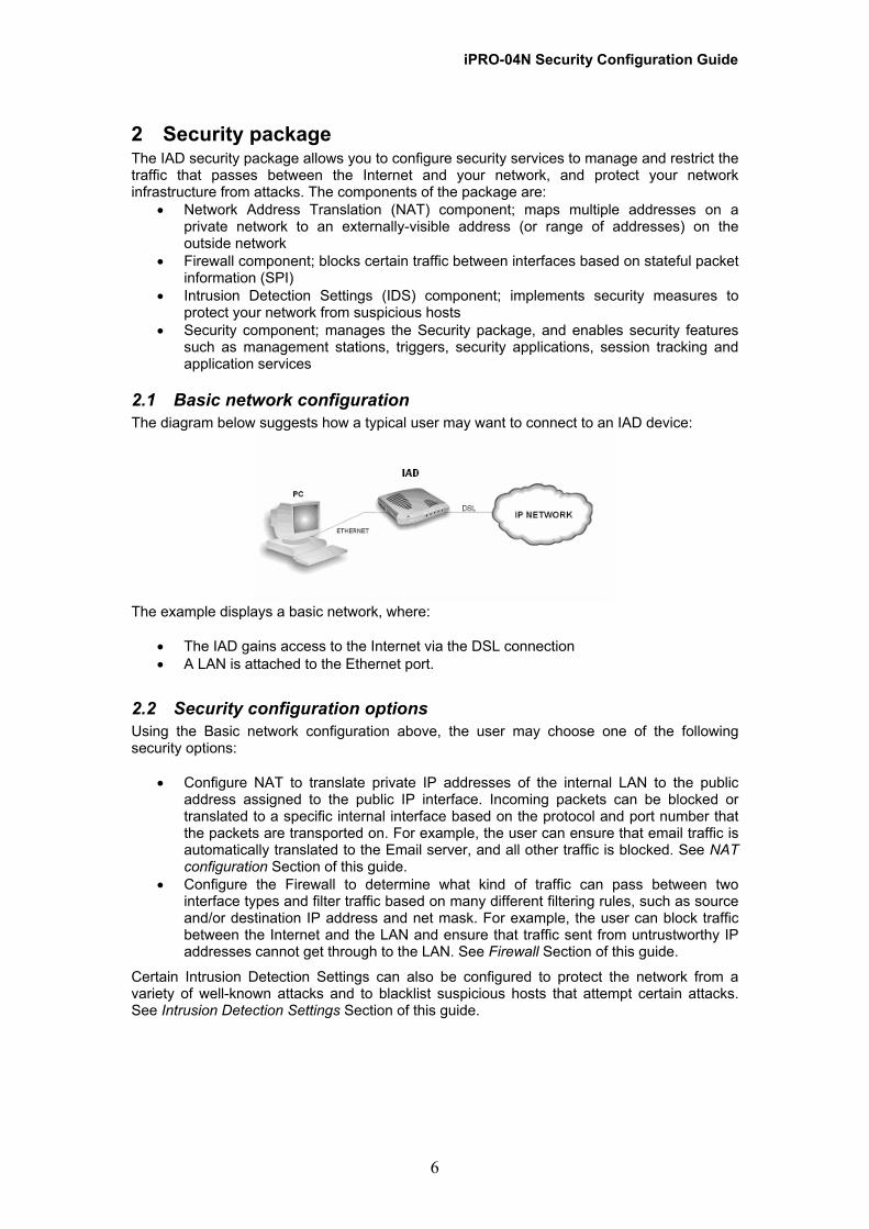
2.1 Basic network configuration The diagram below suggests how a typical user may want to connect to an IAD device:
The example displays a basic network, where:
• The IAD gains access to the Internet via the DSL connection • A LAN is attached to the Ethernet port.
2.2 Security configuration options Using the Basic network configuration above, the user may choose one of the following security options:
• Configure NAT to translate private IP addresses of the internal LAN to the public address assigned to the public IP interface. Incoming packets can be blocked or translated to a specific internal interface based on the protocol and port number that the packets are transported on. For example, the user can ensure that email traffic is automatically translated to the Email server, and all other traffic is blocked. See NAT configuration Section of this guide.
• Configure the Firewall to determine what kind of traffic can pass between two interface types and filter traffic based on many different filtering rules, such as source and/or destination IP address and net mask. For example, the user can block traffic between the Internet and the LAN and ensure that traffic sent from untrustworthy IP addresses cannot get through to the LAN. See Firewall Section of this guide.
Certain Intrusion Detection Settings can also be configured to protect the network from a variety of well-known attacks and to blacklist suspicious hosts that attempt certain attacks. See Intrusion Detection Settings Section of this guide.
6

iPRO-04N Security Configuration Guide
3 The Security package The components of the Security package allow you to configure security services to manage and restrict the traffic that passes between the Internet and your network. This section provides an overview of the package, including details of how it is supported within the IAD.
3.1 Components of the Security package
3.1.1 Network Address Translation (NAT) component The NAT component allows you to map multiple addresses on a private inside network to a single, externally visible address on the outside network. It allows you to keep internal IP addresses private, but still communicate with the outside world via the externally visible address. In the example network below, the PCs attached to the internal network can send information to external PCs, but the messages will appear to come from the external address 10.1.1.1 and not any of the addresses on the 192.168.1.1 subnet.
You can also configure NAT to translate incoming packets based on the protocol and port number(s) that the packets are transported on. For more information about the NAT, see Network Address Translation (NAT) Section of this guide.
3.1.2 Firewall component This component implements a stateful Firewall that provides high security by blocking certain traffic between interfaces based on stateful information. It allows you to control the traffic flow on default data paths called policies, using the following rules:
• Port filter rules; control traffic based on TCP/UDP IP protocol and port number of IP packets
• Host validator rules; control traffic based on specific IP addresses In the network example below, a filter has been created on the data path between the Firewall’s external interface and the DMZ interface. This allows external hosts access to the server via HTTP but not to the internal network.
7

iPRO-04N Security Configuration Guide
3.1.3 Intrusion Detection Settings (IDS) component The IDS component protects your network from suspicious hosts attempting to damage your network or prevent legitimate users from using it. IDS allows you to blacklist and log certain types of attack attempted by suspicious hosts, ensuring that traffic from such hosts is rejected for a certain time limit. For more information about the implementation of IDS, see Intrusion Detection Settings Section of this guide.
3.1.4 Security component The Security component allows you to enable/disable the entire Security package and defines the role of each existing IP interface in the Security network. You cannot configure the Firewall or NAT components until security is enabled and each IP interface in the network is defined as either internal, external or DMZ. See Configuring the Security package Section of this guide and Security Interfaces Section of this guide. This component also allows you to configure:
• Triggers; allows an application to open a secondary port in order to transport data. See Security Triggers Section of this guide.
• Management stations; allows a specific host (or range of hosts) remote access to the device without having to go through NAT and/or Firewall. See Remote Access and Management Stations Section of this guide.
• Security applications; allows incoming access for an Internet application to a specific LAN PC without having to configure NAT or Firewall services. See Security Applications Section of this guide.
• Application services; IP services such as FTP or TFTP servers are offered on specific, well- known port numbers, and by default, all requests received from any IP interface are accepted. You can restrict access to a specific application service on a specific IP interface once the interfaces have been defined as either internal, external or DMZ. See the IP AppServices section of the CLI Reference Manual.
• Logging; allows you to configure the Security logging module. See Configuring Security logging Section of this guide. This logs the following events:
o Intrusion events; logs details of attempted DoS, port scanning and web spoofing attacks including the name of the attack, the port number used and the source/destination IP addresses.
o Blocking events; if an intrusion has been detected, this logs details of the blocked/blacklisted host including their IP address and the length of time they will be blocked/blacklisted for.
o Session events; logs details of session activity when a session is timed-out when it finishes naturally and is removed from the session list. For information about sessions, see Session tracking.
8

iPRO-04N Security Configuration Guide 3.2 Basic Configuration of the Security package
3.2.1 Enabling/disabling Security Before you can configure NAT, Firewall or IDS, you must enable security by entering the following CLI command: security enable To disable the package, enter: security disable
3.3 Displaying information about Security To display information about the entire Security package, enter: security status
Security enabled. Firewall enabled. Firewall security level: none. NAT enabled on ipwan. Intrusion detection is enabled. Security logging is enabled. Session logging enabled. Blocking logging enabled. Intrusion logging disabled.
The next step after enabling Security is to create security interfaces. See Security Interfaces Section of this guide.
3.3.1 Enabling the logging module Before you can log intrusion, blocking and session events, enable the logging module by entering: security enable logging To disable the logging module, enter: security disable logging
3.3.2 Displaying logging module status To display details about the status of the logging module, enter: security list logging
The logging module is : true Session event logging is : true at level notice, log to console false Blocking event logging is : true at level notice, log to console false Intrusion event logging is : false
By default, the logging module is enabled, session event and blocking event logging are enabled and intrusion event logging is disabled. To change these details, see below.
3.3.3 Configuring logging activities Once you have enabled the logging module, enable/disable logging activity by entering: security {enable|disable} {blockinglog|intrusionlog|sessionlog To send log output to the console, use the following command: security {enable|disable} {blockinglog|intrusionlog|sessionlog} [consoleprinting] For example, the following log output is displayed at the console when an Ascend Kill attack is detected:
Intrusion Ascend kill(9) -- 192.168.1.2 > 192.168.100.100 Intrusion Host Blacklisted(0) -- Source IP = 192.168.1.2, Duration = 1800 seconds
9

iPRO-04N Security Configuration Guide The first line displays an intrusion event and logs an attempted Ascend Kill attack destined for the LAN IP address 192.168.1.2 from external IP address 192.168.100.100 using UDP port 9. The second line displays a blocking event and logs the blocking of traffic from the attacker’s IP address to the device’s LAN IP address for the default duration. For each logging event you can also set the minimum level of logging that is reported. The levels available in this command correspond to syslog levels (emergency, alert, critical, error, warning, notice, informational, debug). Enter: security set [blockinglog|intrusionlog|sessionlog] <level> The default reporting level for an enabled log activity is notice, which will report emergency, alert, critical, error, warning and notice messages but not the informational or debug messages.
10

iPRO-04N Security Configuration Guide
4 Security Interfaces Security interfaces must be created before you can configure the majority of features provided by the Security package.
4.1 Security interface overview A security interface is an existing IP interface that has been defined as either internal, external or dmz, depending on its role in the security network. For example, NAT and Firewall rules cannot be configured between the router’s IP interfaces until the role of each IP interface in the security network has been defined. Consider the following basic network:
This is a common security interface configuration, where:
• The LAN IP interface that connects the router to the inside network is defined as the internal interface
• The WAN IP interface that connects the router to the Internet and other networks is defined as the external interface
• The De-Militarized Zone (DMZ) IP interface that connects the router to the inside DMZ network is defined as the DMZ interface
Internal and external security interfaces can also be described as inside and outside interfaces respectively. Inside and outside interfaces are attached to different networks. For example:
• The network attached to an outside network (such as the WAN) contains hosts that may pose a security threat to the inside interfaces (such as the LAN)
• The network attached to an inside network (LAN) needs to be protected from the network attached to the outside interface (WAN)
A DMZ interface is largely accepted as an inside interface because it still requires protection for the outside network. See DMZ interface Section of this guide. Before you can create security interfaces, you must first: 1. Enable the Security package 2. Configure the router’s IP interfaces
4.2 DMZ interface A demilitarized zone (DMZ) is a host or small network that acts as neutral ground between the inside and outside network. It contains information that is useful to users of both the inside and outside network. For example, a company may wish to provide software patches to customers via an FTP server. However, it does not want FTP access to any hosts other than the FTP server. This is achieved by creating a DMZ network, which is less restrictive than the
11
iPRO-04N Security Configuration Guide internal network. Users attached to the outside network can access the DMZ, but they cannot access any other company data. See the network diagram in the Firewall component section of this manual for details of where the DMZ fits in to the basic network.
4.2.1 Virtual DMZ interface If you want to use a DMZ in your IAD you can only create a virtual DMZ interface. The DMZ virtual interface appears as a separate internal interface. DMZ traffic is transported to the router via the Ethernet transport attached to the LAN interface.
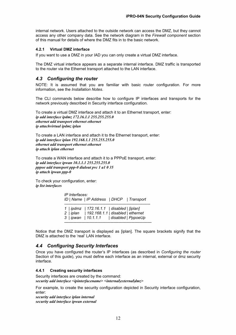
4.3 Configuring the router NOTE: It is assumed that you are familiar with basic router configuration. For more information, see the Installation Notes. The CLI commands below describe how to configure IP interfaces and transports for the network previously described in Security interface configuration. To create a virtual DMZ interface and attach it to an Ethernet transport, enter: ip add interface ipdmz 172.16.1.1 255.255.255.0 ethernet add transport ethernet ethernet ip attachvirtual ipdmz iplan To create a LAN interface and attach it to the Ethernet transport, enter: ip add interface iplan 192.168.1.1 255.255.255.0 ethernet add transport ethernet ethernet ip attach iplan ethernet To create a WAN interface and attach it to a PPPoE transport, enter: ip add interface ipwan 10.1.1.1 255.255.255.0 pppoe add transport ppp-0 dialout pvc 1 a1 0 35 ip attach ipwan ppp-0 To check your configuration, enter: ip list interfaces
IP Interfaces: ID | Name | IP Address | DHCP | Transport ----------------------------------------------------------------- 1 | ipdmz | 172.16.1.1 | disabled | [iplan] 2 | iplan | 192.168.1.1 | disabled | ethernet 3 | ipwan | 10.1.1.1 | disabled | PppoeUp ------------------------------------------------------------------
Notice that the DMZ transport is displayed as [iplan]. The square brackets signify that the DMZ is attached to the ‘real’ LAN interface.
4.4 Configuring Security Interfaces Once you have configured the router’s IP interfaces (as described in Configuring the router Section of this guide), you must define each interface as an internal, external or dmz security interface.
4.4.1 Creating security interfaces Security interfaces are created by the command: security add interface <ipinterfacename> <internal|external|dmz>
For example, to create the security configuration depicted in Security interface configuration, enter: security add interface iplan internal security add interface ipwan external
12

iPRO-04N Security Configuration Guide security add interface ipdmz dmz You can define more than one IP interface with the same security definition. For example, you may configure your Ethernet and virtual ports to support two separate inside networks and define both IP interfaces as internal security interfaces.
Note: Creating IP interfaces via the web page will be automatically assigned a security interface.
4.4.2 Deleting security interfaces To delete a single security interface, enter: security delete interface <interfacename>
To delete all existing security interfaces, enter: security clear interfaces
4.4.3 Displaying information about security interfaces To list existing interfaces, enter: security list interfaces
Security Interfaces: ID |Name |Type -------------------------------------- 1 | ipdmz | dmz 2 | iplan | internal 3 | ipwan | external --------------------------------------
To display details of the security interface defined on a specific IP interface, such as the iplan interface, enter: security show interface
iplan Interface name: iplan Interface type: internal
13
iPRO-04N Security Configuration Guide
5 Firewall Before you start configuring the Firewall, you must:
• Configure the router. • Enable the security package. • Create security interfaces.
5.1 What is a stateful Firewall? A stateful Firewall tracks the movement of packets over a period of time. If an outgoing packet includes a request for responses from certain types of incoming packet, the packet is tracked to ensure that only those types of incoming packets are allowed through the Firewall. Other types of traffic are blocked. Each time outbound packets are sent from an inside host to an outside host, the following stateful information is logged by the Firewall:
• Source and destination addresses • Port details; protocol type and range of source and destination ports sequencing
information • Additional flags for each connection associated with that particular inside host
All inbound packets are compared against this logged information and any manually configured address and port details. These packets are only allowed through the Firewall if an appropriate connection exists or if a filter explicitly allows that traffic. Address and port details are configured by defining Firewall validators and filters (see Firewall validators and Firewall filters Sections of this guide). This makes it very difficult for hackers to break through the stateful Firewall, because they would need to know addresses, port numbers, sequencing information and individual connection flags for an inside host.
5.1.1 Enabling/disabling the Firewall You must enable the Firewall module before you can start configuring it. Enter: firewall enable To disable it, enter: firewall disable To check the status of the Firewall module, enter: firewall status
firewall disabled. firewall security level: none.
5.1.2 Default Firewall Security levels The Firewall module contains default security levels that provide none, high, medium or low network security. Each level contains pre-configured filter rules for the most commonly used services, including HTTP, DNS and SMTP. Different incoming and outgoing filter rules determine whether services are allowed or blocked for each security level. NOTE: When enabling the Firewall the default setting is ‘none’ – this level has no port filters or host validators configured, therefore it will block all traffic. For more details of Firewall security levels, see Default Firewall Security levels. Default levels are optional. If a level contains filter configurations that meet the security requirements of your network, you can set that level and avoid having to manually configure every filter. If the levels do not meet your security network requirements, you can add or remove them manually.
14
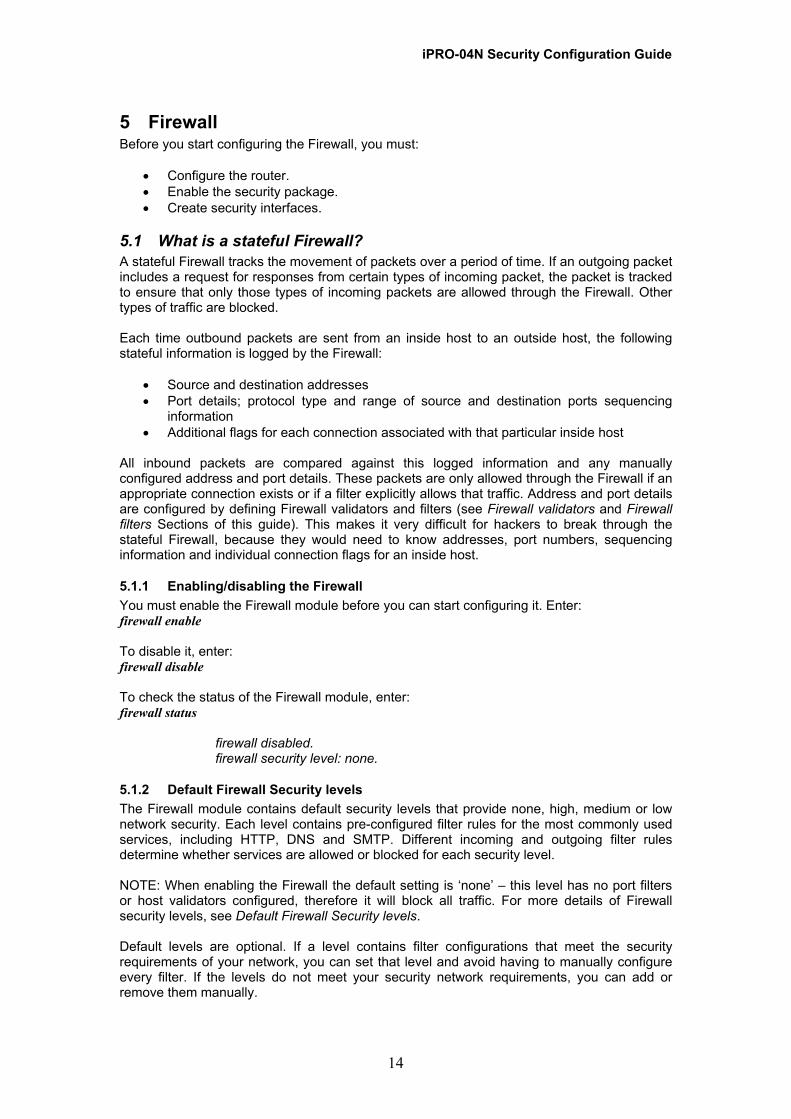
iPRO-04N Security Configuration Guide The following tables provide details of each security level’s filter rules between each policy. The tables tell you that each service cannot be received in or allowed out by a specific policy. (Y=yes; N=no):
5.1.3 ‘None’ security level The ‘None’ security level provides the highest level of network protection because it blocks all outgoing and incoming services between policies as it does not contain any port filters or validators - this the default Firewall level.
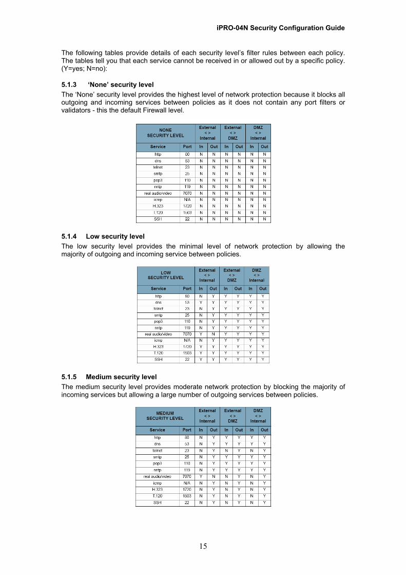
5.1.4 Low security level The low security level provides the minimal level of network protection by allowing the majority of outgoing and incoming service between policies.
5.1.5 Medium security level The medium security level provides moderate network protection by blocking the majority of incoming services but allowing a large number of outgoing services between policies.
15

iPRO-04N Security Configuration Guide 5.1.6 High security level The high security level provides a major level of network protection by blocking the majority of incoming services and a large number of outgoing services between policies.
5.1.7 Enabling/disabling security levels The ‘None’ sercurity level is enabled by default. To enable a security level, enter: firewall set securitylevel {none | high | medium | low } Once you have enabled a security level, you can add manually configured filters to it. If you then save your configuration using the system config save command, these additional filters are saved as part of the default level and are restored on reboot. Enabling a security level automatically deletes and replaces the previous security level or any filters set. For example, if you have manually-configured a number of filters as described in Firewall filters, the filters defined for the enabled level will replace them.
5.1.8 Displaying information about security levels To check if a security level is set, enter: firewall status
Firewall enabled. Firewall security level: high.
5.1.9 Firewall policies A policy is the name of the rule that applies to a data path between two classes of security interface. You can add different address validator and filter rules to each policy in order to provide different levels of security to the inside networks attached to the router. For example, if your DMZ contains an FTP server that can be accessed by external hosts, the rules between the dmz and external security interfaces will be less stringent than those between the internal and external security interfaces. Policies exist by default:
• Between the external interface and the internal interface • Between the external interface and the DMZ interface • Between the DMZ interface and the internal interface
Policies are set to block only the IP addresses specified in validator rules. See Firewall validators Section of this guide. If you have configured your router and created security interfaces as described in Security Interfaces Section of this guide, the data paths between each of the router’s security interfaces look like this:
16

iPRO-04N Security Configuration Guide
5.1.10 Displaying information about policies To display information about policies, enter: firewall list policies
Firewall Policies: ID | Name | Type1 | Type2 | Validator Allow Only -------------------------------------------------------------- 1 | ext-int | external | internal | false 2 | ext-dmz | external | dmz | false 3 | dmz-int | dmz | internal | false --------------------------------------------------------------
The output displays the name of each policy, the types of security interfaces that the policy exists between and the validator rule status (see Firewall validators Section of this guide). To display information about an individual policy, such as the external-internal policy, enter: firewall show policy ext-int
Firewall Policy : external-internal Interface Type 1 : external Interface Type 2: internal Allow Only Validator : false
5.1.11 Firewall filters A Firewall filter is a rule that determines how the Firewall should handle packets being transported on a policy between two security interfaces. You can create separate filter rules based on:
• The protocol type of the traffic allowed to be transported • Which TCP/UDP port numbers the packets are allowed to be transported on • The name of the well-known protocol, service or application allowed to be transported • Source and destination addresses
Whichever type of filter rule you use, you must also determine which direction packets should be allowed to travel in:
• Inbound; permitted traffic is transported from the outside interface to the inside
interface • Outbound; permitted traffic is transported from the inside interface to the outside
interface • Both; inbound and outbound rules apply • None; does not permit traffic in either direction
For definitions of inside and outside interface, see Security interface. NOTE: If you create a filter and the want to change the direction that packets are allowed to travel in, you must delete the original filter and create another.
17
iPRO-04N Security Configuration Guide 5.1.12 Creating a filter based on protocol number A filter based on the protocol number and direction of traffic is created by entering the following: firewall add portfilter <name> <policyname> {protocol <protocol>} {inbound|outbound|both|none} In this command, the <protocol> attribute is the number of a protocol defined in Assigned Numbers RFC 1700. The following command adds a filter rule to the dmz-external policy, which allows inbound IGMP packets: firewall add portfilter pf1 external-dmz protocol 2 inbound
5.1.13 Creating a filter based on TCP/UDP port range A filter based on the TCP or UDP protocol, port range and direction of traffic, is created by entering: firewall add portfilter <name> <policyname> {tcp|udp} <startport> <endport> {inbound|outbound|both|none} In this command, the <startport> and <endport> attributes allow you to specify the TCP or UDP port range that packets can be transported on. The following command adds a filter rule to the external-internal policy, which allows outbound DNS packets using UDP port 53: firewall add portfilter pf2 internal-external udp 53 53 outbound Note: that if packets are only to be transported on a single port, the same port should be specified for both the <startport> and <endport> attributes.
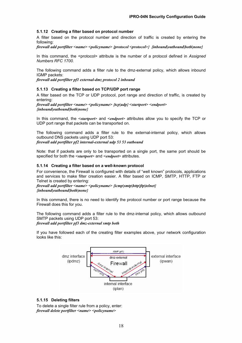
5.1.14 Creating a filter based on a well-known protocol For convenience, the Firewall is configured with details of “well known” protocols, applications and services to make filter creation easier. A filter based on ICMP, SMTP, HTTP, FTP or Telnet is created by entering: firewall add portfilter <name> <policyname> {icmp|smtp|http|ftp|telnet} {inbound|outbound|both|none} In this command, there is no need to identify the protocol number or port range because the Firewall does this for you. The following command adds a filter rule to the dmz-internal policy, which allows outbound SMTP packets using UDP port 53: firewall add portfilter pf3 dmz-external smtp both If you have followed each of the creating filter examples above, your network configuration looks like this:
5.1.15 Deleting filters To delete a single filter rule from a policy, enter: firewall delete portfilter <name> <policyname>
18

iPRO-04N Security Configuration Guide To delete all existing filter rules from a policy, enter: firewall clear portfilters <policyname>
5.1.16 Displaying information about filters To display information about each filter created on a specific policy, such as the external-internal policy, enter: firewall list portfilters ext-int
ID | Name | Type | Port Range | In | Out | Raw | TCP | UDP ------------------------------------------------------------------------------------------------ 1 | pf3 | 6 | 25 - 25 | true | true | false | true | false 2 | pf2 | 17 | 53 - | false | true | false | false | true 3 | pf1 | 2 | 0 - 0 | true | false | true | false | false ------------------------------------------------------------------------------------------------
To display information about a specific filter added to a policy such as the dmz-internal policy, enter: firewall show portfilter pf3 ext-int
Firewall Port Filter : pf3 Transport type : 6 Port number start : 25 Port number end : 25 Inbound permission : true Outbound permission : true Raw IP: false TCP permission : true UDP permission : false
The command output above lists the parameters that were defined when the filter was created.
5.1.17 Firewall validators A Firewall validator is a rule that determines how the Firewall should handle packets received from or sent to a specific IP address or a range of addresses. If you know the address details of a specific external host whom you believe may attempt to infiltrate or damage your internal network, you can block traffic from that host. Similarly, if an internal host is accessing an external web site that contains unacceptable material, you can block their access to it. You must also determine which direction packets should be allowed to travel in:
• Inbound; permitted traffic is transported from the outside interface to the inside interface
• Outbound; permitted traffic is transported from the inside interface to the outside interface
• Both; inbound and outbound rules apply For definitions of inside and outside interface, see Security interface overview.
5.1.18 Creating a validator A validator is created by entering: firewall add validator <name> <policyname> {inbound|outbound|both|none} <ipaddress><hostipmask> To block traffic on a specific IP address, enter the <hostipmask>, e.g., 255.255.255.255 To block a range of IP addresses, enter the specific <hostipmask> attribute, 255.255.255.0 In this command, the <protocol> attribute is the number of a non-TCP or non-UDP protocol defined in RFC 1700.
19
iPRO-04N Security Configuration Guide In the command below, a validator is created to block traffic from a suspicious external host (10.1.1.2 255.255.255.255) destined for a PC attached to the internal network: firewall add validator suspect_in ext-int inbound 10.1.1.2 255.255.255.255 In the command below, a validator is created to block traffic sent from PCs on the internal network to an external web site hosted by the 156.64.48.37 subnet: firewall add validator suspect_out ext-int outbound 156.64.48.37 255.255.255.0
5.1.19 Deleting validators To delete a single validator rule from a policy, enter: firewall delete validator <name> <policyname> To delete all existing filter rules from a policy, enter: firewall clear validators <policyname>
5.1.20 Displaying information about validators To display information about each validator created on a specific policy, such as the external- internal policy, enter: firewall list validators ext-int
Firewall Host Validators: ID | Name | Direction | Host IP | Mask ------------------------------------------------------------------------------- 1 | suspect_in | inbound | 10.1.1.2 | 255.255.255.255 2 | suspect_out | outbound | 156.64.48.37 | 255.255.255.0 -------------------------------------------------------------------------------
To display information about a specific validator added to a policy such as the external-internal policy, enter: firewall show validator ext-int
Firewall Host Validator : suspect_in Direction : inbound Host IP : 10.1.1.2 Host Mask : 255.255.255.0
20

iPRO-04N Security Configuration Guide
6 Network Address Translation (NAT) NAT allows you to connect multiple computers to the Internet (or any other IP network) using one IP address. This chapter describes what kind of NAT is supported by the IAD and provides example network configurations.
Before configuring NAT, you must first enable the security package; see Enabling/disabling Security Section of this guide
6.1 Overview of IAD support for NAT In addition to basic NAT, the IAD implementation also supports: • Network Address Port Translation (NAPT) • NAT multiple IPsec session pass-through
6.1.1 What is basic NAT? Basic NAT is a router function (described in RFC 1631) that determines how to translate network IP addresses. As data packets are received on the device’s interfaces, data in their protocol headers is compared to criteria established in NAT rules through global pools and reserved mappings. The criteria include ranges of source or destination addresses. If the packet meets the criteria of one of the rules, the packet header undergoes the translation specified by the mapping and the revised packet is forwarded. If the packet does not meet the criteria, it is discarded. IAD supports both static and dynamic versions of NAT:
• Static NAT: defines a fixed address translation from the internal network to the external network
• Dynamic NAT: translates from a pool of local IP addresses to a pool of global IP addresses
NAT provides a mechanism for reducing the need for globally unique IP addresses. It allows you to use addresses that are not globally unique on your internal network and translate them to a single globally unique external address.
6.1.2 Enabling and disabling NAT NAT can be enabled between each data path in the network. Data paths exist between each existing outside security interface (external or dmz) and each interface that belongs to a specific inside interface type (internal or dmz). In this way, the IP address of a host on a network attached to an inside interface is hidden from a host on a network attached to an outside interface. To enable NAT, enter: nat enable <name> <interfacename> {internal|dmz} To disable NAT, enter: nat disable You can have any of the following outside to inside interface combinations enabled simultaneously:
• NAT enabled between the external (outside) interface and internal (inside) interface(s)
• NAT enabled between the external (outside) interface and dmz (inside) interface(s) • NAT enabled between the dmz (outside) interface and internal (inside) interface(s)
If your DMZ is frequently accessed by external hosts, it may carry a higher risk of being compromised compared with the internal LAN. Enabling NAT between the dmz and internal
21
iPRO-04N Security Configuration Guide interfaces provides an extra layer of security between the DMZ and the internal network. Unique or reserved mappings can be configured on each data path (external - internal and external - dmz) and traffic translated between the two data paths remains completely separate. To achieve this configuration, see NAT configuration later in this Section of this guide
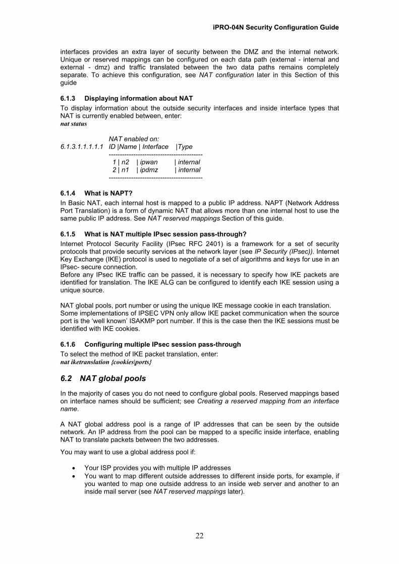
6.1.3 Displaying information about NAT To display information about the outside security interfaces and inside interface types that NAT is currently enabled between, enter: nat status
NAT enabled on: 6.1.3.1.1.1.1.1 ID |Name | Interface |Type
------------------------------------------ 1 | n2 | ipwan | internal 2 | n1 | ipdmz | internal ------------------------------------------
6.1.4 What is NAPT? In Basic NAT, each internal host is mapped to a public IP address. NAPT (Network Address Port Translation) is a form of dynamic NAT that allows more than one internal host to use the same public IP address. See NAT reserved mappings Section of this guide.
6.1.5 What is NAT multiple IPsec session pass-through? Internet Protocol Security Facility (IPsec RFC 2401) is a framework for a set of security protocols that provide security services at the network layer (see IP Security (IPsec)). Internet Key Exchange (IKE) protocol is used to negotiate of a set of algorithms and keys for use in an IPsec- secure connection. Before any IPsec IKE traffic can be passed, it is necessary to specify how IKE packets are identified for translation. The IKE ALG can be configured to identify each IKE session using a unique source. NAT global pools, port number or using the unique IKE message cookie in each translation. Some implementations of IPSEC VPN only allow IKE packet communication when the source port is the ‘well known’ ISAKMP port number. If this is the case then the IKE sessions must be identified with IKE cookies.
6.1.6 Configuring multiple IPsec session pass-through To select the method of IKE packet translation, enter: nat iketranslation {cookies|ports}
6.2 NAT global pools
In the majority of cases you do not need to configure global pools. Reserved mappings based on interface names should be sufficient; see Creating a reserved mapping from an interface name. A NAT global address pool is a range of IP addresses that can be seen by the outside network. An IP address from the pool can be mapped to a specific inside interface, enabling NAT to translate packets between the two addresses.
You may want to use a global address pool if:
• Your ISP provides you with multiple IP addresses • You want to map different outside addresses to different inside ports, for example, if
you wanted to map one outside address to an inside web server and another to an inside mail server (see NAT reserved mappings later).
22
iPRO-04N Security Configuration Guide 6.3 Creating a global pool To create a global pool, enter: nat add globalpool <name> <interfacename> {internal|dmz} <ipaddress> {subnetmask <mask>|endaddress <address>}
The <interfacename> is the name of an existing outside security interface (external or dmz) previously created and connected to an inside interface (dmz or internal) using the nat enable command. You can specify a range of IP addresses either by:
• Specifying the <interfacename> IP address and subnet mask address • Specifying the <interfacename> IP address that represents the first address in the
range, then specifying the last address in the range The following example creates a global pool with a range from 192.168.103.2 to 192.168.103.50: nat add globalpool gp1 extinterface internal 192.168.103.2 endaddress 192.168.103.50
6.3.1 Deleting global pools To delete an existing global pool previously added to a specific outside interface, enter: nat delete globalpool <name> <interfacename>
To clear all existing global pools previously added to a specific outside interface, enter: nat clear globalpools <interfacename>
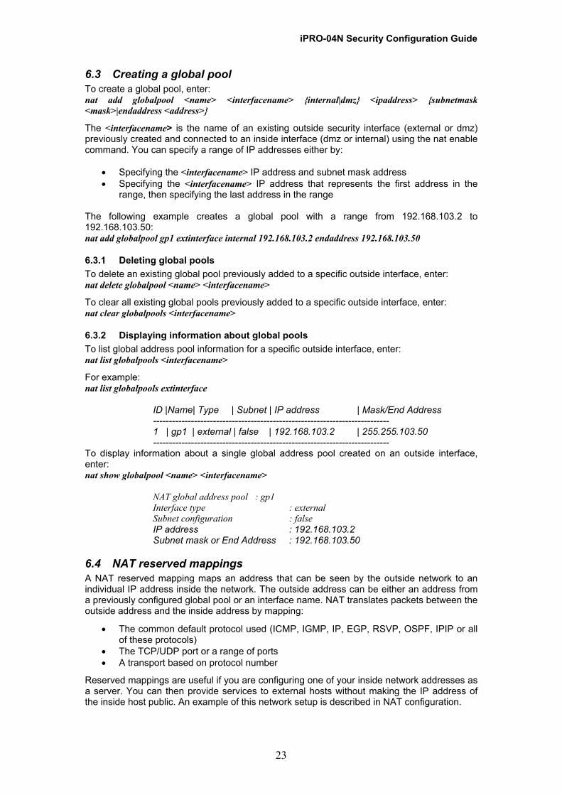
6.3.2 Displaying information about global pools To list global address pool information for a specific outside interface, enter: nat list globalpools <interfacename>
For example: nat list globalpools extinterface
ID |Name| Type | Subnet | IP address | Mask/End Address --------------------------------------------------------------------------- 1 | gp1 | external | false | 192.168.103.2 | 255.255.103.50 ---------------------------------------------------------------------------
To display information about a single global address pool created on an outside interface, enter: nat show globalpool <name> <interfacename>
NAT global address pool : gp1 Interface type : external Subnet configuration : false IP address : 192.168.103.2 Subnet mask or End Address : 192.168.103.50
6.4 NAT reserved mappings A NAT reserved mapping maps an address that can be seen by the outside network to an individual IP address inside the network. The outside address can be either an address from a previously configured global pool or an interface name. NAT translates packets between the outside address and the inside address by mapping:
• The common default protocol used (ICMP, IGMP, IP, EGP, RSVP, OSPF, IPIP or all of these protocols)
• The TCP/UDP port or a range of ports • A transport based on protocol number
Reserved mappings are useful if you are configuring one of your inside network addresses as a server. You can then provide services to external hosts without making the IP address of the inside host public. An example of this network setup is described in NAT configuration.
23
iPRO-04N Security Configuration Guide 6.4.1 Configuring reserved mappings You can create a NAT reserved mapping that translates from an outside interface to an inside interface based on either:
• The outside interface name - no global address configuration is necessary • A global IP address previously created on the outside interface
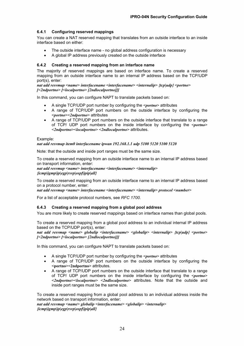
6.4.2 Creating a reserved mapping from an interface name The majority of reserved mappings are based on interface name. To create a reserved mapping from an outside interface name to an internal IP address based on the TCP/UDP port(s), enter: nat add resvmap <name> interfacename <interfacename> <internalip> {tcp|udp} <portno> [<2ndportno> [<localportno> [2ndlocalportno]]]
In this command, you can configure NAPT to translate packets based on:
• A single TCP/UDP port number by configuring the <portno> attributes • A range of TCP/UDP port numbers on the outside interface by configuring the
<portno><2ndportno> attributes • A range of TCP/UDP port numbers on the outside interface that translate to a range
of TCP/ UDP port numbers on the inside interface by configuring the <portno> <2ndportno><localportno> <2ndlocalportno> attributes.
Example: nat add resvmap item0 interfacename ipwan 192.168.1.1 udp 5100 5120 5100 5120
Note: that the outside and inside port ranges must be the same size.
To create a reserved mapping from an outside interface name to an internal IP address based on transport information, enter: nat add resvmap <name> interfacename <interfacename> <internalip> {icmp|igmp|ip|egp|rsvp|ospf|ipip|all}
To create a reserved mapping from an outside interface name to an internal IP address based on a protocol number, enter: nat add resvmap <name> interfacename <interfacename> <internalip> protocol <number>
For a list of acceptable protocol numbers, see RFC 1700.
6.4.3 Creating a reserved mapping from a global pool address You are more likely to create reserved mappings based on interface names than global pools. To create a reserved mapping from a global pool address to an individual internal IP address based on the TCP/UDP port(s), enter: nat add resvmap <name> globalip <interfacename> <globalip> <internalip> {tcp|udp} <portno> [<2ndportno> [<localportno> [2ndlocalportno]]] In this command, you can configure NAPT to translate packets based on:
• A single TCP/UDP port number by configuring the <portno> attributes • A range of TCP/UDP port numbers on the outside interface by configuring the
<portno><2ndportno> attributes. • A range of TCP/UDP port numbers on the outside interface that translate to a range
of TCP/ UDP port numbers on the inside interface by configuring the <portno> <2ndportno><localportno> <2ndlocalportno> attributes. Note that the outside and inside port ranges must be the same size.
To create a reserved mapping from a global pool address to an individual address inside the network based on transport information, enter: nat add resvmap <name> globalip <interfacename> <globalip> <internalip> {icmp|igmp|ip|egp|rsvp|ospf|ipip|all}
24

iPRO-04N Security Configuration Guide 6.4.4 Deleting reserved mappings To delete a single NAT reserved mapping definition previously added to a specific outside interface, enter: nat delete resvmap <name> <interfacename> To delete all NAT reserved mapping definitions previously added to a specific outside interface, enter: nat clear resvmaps <interfacename>
6.4.5 Displaying information about reserved mappings To list reserved mapping information for a specific outside interface, enter: nat list resvmaps <interfacename> For example: nat list resvmaps ipwan
NAT reserved mappings:
ID |Name | Global Address |Internal Address |Type |Ext Port Range | Local Port Range ---------------------------------------------------------------------------------------------------------------- 1 |rm1 | 192.168.103.2 |10.10.10.10 |tcp |21-21 |21-21 2 |rm2 | 0.0.0.0 |20.20.20.20 |udp |5100-5120 |5100-5120 3 |rm2 | 192.168.103.15 |30.30.30.30 |udp |30-38 |130-138 -----------------------------------------------------------------------------------------------------------------
NOTE: A global address of 0.0.0.0 indicates that the IP address of the interface is used. In the above example:
• rm1 is mapped from a global address using a single port • rm2 is mapped from the external interface using the same port range for each
interface • rm3 is mapped from a global address using different port ranges for each interface
To display information about a single reserved mapping, enter: nat show resvmap <name> <interfacename> For example: nat show resvmap rm1 extinterface
NAT reserved mapping : rm1 Global IP address : 192.168.103.2 Internal IP address : 10.10.10.10 Transport type : tcp Port number : 21
25

iPRO-04N Security Configuration Guide 6.5 NAT configuration Consider the following network diagram:
In this network, three LAN PCs are attached to the router via an Ethernet hub. Each of the PCs has a private IP address on the LAN subnet mask address 192.168.1.1 255.255.255.0. Specific types of traffic are mapped between the external interface and two of the internal PCs so that NAT can translate packets as follows:
• ICMP packets are translated between the external interface and PC B • HTTP and HTTPS packets are translated between the external interface and PC C
PC A cannot receive any uninitiated packets from the external interface, because no reserved mappings are configured.
6.5.1 Router configuration It is assumed that you have already configured the router as follows:
• Created two IP interfaces; iplan (internal) and ipwan (external) • Attached an Ethernet transport to iplan • Attached an ATM transport to ipwan
For more information about router configuration, see Configuring the router Section of this guide
6.5.2 NAT configuration Create external and internal security interfaces: security add interface iplan internal security add interface ipwan external Enable NAT between the external and internal interface: nat enable nat1 ipwan internal Create a reserved mapping to ensure that email traffic is translated between the external interface and PC B: nat add resvmap email interfacename ipwan 192.168.1.50 smtp Create reserved mappings to ensure that HTTP and HTTPS traffic is translated between the external interface and PC C: nat add resvmap web1 interfacename ipwan 192.168.1.75 tcp 80 nat add resvmap web2 interfacename ipwan 192.168.1.75 tcp 443
26
iPRO-04N Security Configuration Guide
7 Intrusion Detection Settings The IAD Security package includes Intrusion Detection Settings (IDS) that provide protection from attempted attacks. Intrusion Detection Settings are network protection features that can be configured to guard against certain Denial of Service, port scanning and web spoofing attacks. Any attempt to attack or scan the network causes traffic originating from the attacker’s machine to be blacklisted for a set time limit. Details of attempted attacks can also be logged and displayed at the CLI. This section contains the following Section of this guide:
• Basic IDS configuration; describes how to enable IDS and display IDS details. • Configuring blacklisting; describes how to enable, configure and display blacklisting
information. • Basic network configuration; describes the basic network configuration used to test
IDS. • Port Scan attacks; describes how to configure IDS to protect against certain port scan
attacks. Details of how to test specific intrusion detect settings are also included. • Denial of Service (DoS) attacks, describes how to configure IDS to protect against
certain DoS attacks. Details of how to test specific intrusion detect settings are also included.
Before you start configuring Intrusion Detection Settings, you must enable the security package. See Enabling/disabling Security.
7.1 Basic IDS configuration
7.1.1 Enabling/disabling IDS IDS commands are part of the security module. Once you have enabled security, you can enable intrusion detection by entering: security enable IDS To disable IDS, enter: security disable IDS
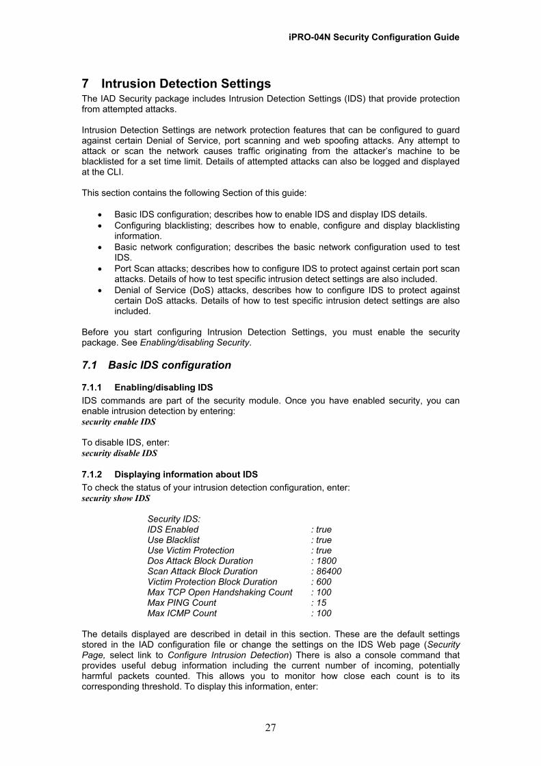
7.1.2 Displaying information about IDS To check the status of your intrusion detection configuration, enter: security show IDS
Security IDS: IDS Enabled : true Use Blacklist : true Use Victim Protection : true Dos Attack Block Duration : 1800 Scan Attack Block Duration : 86400 Victim Protection Block Duration : 600 Max TCP Open Handshaking Count : 100 Max PING Count : 15 Max ICMP Count : 100
The details displayed are described in detail in this section. These are the default settings stored in the IAD configuration file or change the settings on the IDS Web page (Security Page, select link to Configure Intrusion Detection) There is also a console command that provides useful debug information including the current number of incoming, potentially harmful packets counted. This allows you to monitor how close each count is to its corresponding threshold. To display this information, enter:
27
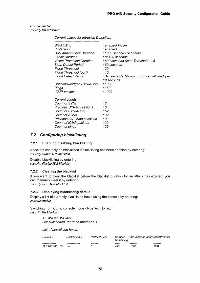
iPRO-04N Security Configuration Guide console enable security list intrusion
Current values for Intrusion Detection: ---------------------------------------- Blacklisting : enabled Victim Protection : enabled DoS Attack Block Duration : 1800 seconds Scanning Block Duration : 86400 seconds Victim Protection Duration : 600 seconds Scan Threshold : 5 Scan Detect Period : 60 seconds Flood Threshold : 20 Flood Threshold (port) : 10 Flood Detect Period : 10 seconds Maximum counts allowed per
10 seconds: Unacknowledged SYN/ACKs : 1000 Pings : 150 ICMP packets : 1000 Current counts: Count of SYNs : 2 Previous SYNed sessions : 0 Count of SYN/ACKs : 52 Count of ACKs : 32 Previous unACKed sessions : 0 Count of ICMP packets : 39 Count of pings : 25
7.2 Configuring blacklisting
7.2.1 Enabling/disabling blacklisting
Attackers can only be blacklisted if blacklisting has been enabled by entering: security enable IDS blacklist
Disable blacklisting by entering: security disable IDS blacklist
7.2.2 Clearing the blacklist If you want to clear the blacklist before the blacklist duration for an attack has expired, you can manually clear it by entering: security clear IDS blacklist
7.2.3 Displaying blacklisting details Display a list of currently blacklisted hosts using the console by entering: console enable Switching from CLI to console mode - type ‘exit’ to return security list blacklist
ALCWGetIDSBlack List succeeded, returned number = 1 List of blacklisted hosts: Source IP Destination IP Protocol Port/ Duration Time Address AddressICMP(secs) Remaining --------------- --------------- -------- ----- -------- --------- 192.168.100.100 n/a 6 445 1800 1799
28
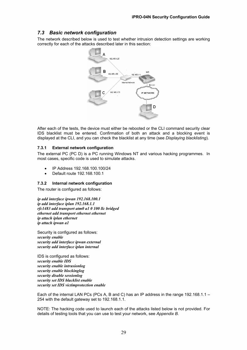
iPRO-04N Security Configuration Guide 7.3 Basic network configuration The network described below is used to test whether intrusion detection settings are working correctly for each of the attacks described later in this section:
After each of the tests, the device must either be rebooted or the CLI command security clear IDS blacklist must be entered. Confirmation of both an attack and a blocking event is displayed at the CLI, and you can check the blacklist at any time (see Displaying blacklisting).
7.3.1 External network configuration The external PC (PC D) is a PC running Windows NT and various hacking programmes. In most cases, specific code is used to simulate attacks.
• IP Address 192.168.100.100/24 • Default route 192.168.100.1
7.3.2 Internal network configuration The router is configured as follows: ip add interface ipwan 192.168.100.1 ip add interface iplan 192.168.1.1 rfc1483 add transport atm0 a1 0 100 llc bridged ethernet add transport ethernet ethernet ip attach iplan ethernet ip attach ipwan a1 Security is configured as follows: security enable security add interface ipwan external security add interface iplan internal IDS is configured as follows: security enable IDS security enable intrusionlog security enable blockinglog security disable sessionlog security set IDS blacklist enable security set IDS victimprotection enable Each of the internal LAN PCs (PCs A, B and C) has an IP address in the range 192.168.1.1 – 254 with the default gateway set to 192.168.1.1. NOTE: The hacking code used to launch each of the attacks listed below is not provided. For details of testing tools that you can use to test your network, see Appendix B.
29

iPRO-04N Security Configuration Guide 7.4 Port Scan attacks An attacker scans a system in an attempt to identify open ports that are listening for a particular service. Scans are performed by sending a message to each port in turn with certain TCP flag headers set. The response received from each port indicates whether the port is in use and can be probed further in an attempt to violate the network. For example, if a weak port is found, the attacker may attempt to send a DoS attack to that port (see Denial of Service (DoS). The Security module offers protection from the port scan attacks listed in the table below. Certain port scan attacks are classed as Trojan Horse attacks. These are programs that may appear harmless, but once executed they can cause damage to your computer and/or allow remote attackers access to it. The default protection measures are the same for each scan attack and are described in Configuring protection against Port Scan attacks.
7.4.1 Configuring protection against Port Scan attacks
The device detects an attempted port scan if it receives more than 5 scanning packets (e.g., SYN/ ACK, FIN or RST packets) per second from a single host. To modify this default threshold, enter: security set IDS scanthreshold <max> The device counts the maximum number of scan packets allowed per second over a 60 second period. To modify this default duration, enter: security set IDS scanperiod <duration> If the number of scanning packets counted within the specified duration is greater than the scan threshold set, the suspected attacker is blocked for 86400 seconds. To modify this default duration, enter: security set IDS SCANattackblock <duration>
30

iPRO-04N Security Configuration Guide
8 Security Triggers This section provides detailed information about using triggers with Firewall, NAT and Application Level Gateways. It contains configuration examples and a list of applications that may require triggers.
8.1 What are triggers? Security triggers deal with application protocols that create separate sessions or need to have binary IP addresses in the payload translated and do not have an Application Level Gateway (ALG). Certain application protocols, such as NetMeeting, open secondary sessions during normal operations. NetMeeting establishes a primary connection to a server using port 1720, but data transfers are performed on separate sessions. The port numbers used and the hosts that requests the secondary sessions may vary. Without security triggers, you could only get NetMeeting to establish secondary sessions by manually configuring a range of port numbers to remain open indefinitely. This is a significant risk to your network security and is not recommended. You can avoid this risk by using security triggers. A trigger is aware of the requirements of application protocols that use secondary sessions. The trigger tells the security mechanism to expect a secondary session and explains how the session should be managed. In this way, triggers deal with secondary sessions dynamically and only when necessary. Your network is still protected by the Firewall (see How do triggers work with the Firewall?) or by NAT (see How do triggers work with NAT?).
8.1.1 How do triggers work with Application Level Gateways? Essentially, triggers and ALGs perform the same function; they deal with difficult applications that your NAT or Firewall configuration cannot manage. However, certain applications prove too difficult for triggers and must be handled by ALGs. The Security module is configured with ALGs for certain well-known applications, such as FTP. These applications are listed in Supported ALGs . If you want to use any of the applications listed, you do not need to create triggers for them.
8.1.2 How do triggers work with the Firewall? In order for a trigger to work with the Firewall, you must create the necessary inbound/outbound portfilter(s) so that the application protocol can establish a primary connection. You do not need to create filters for secondary connections because the trigger creates a ‘hole’ in the Firewall and dynamically opens the required port(s) in order to pass traffic.
8.1.3 How do triggers work with NAT? A trigger lets NAT know which internal host it should direct secondary session packets to. To allow some protocols such as HTTPS (SSL) to work with NAT, you simply have to create a trigger for it. However, when creating triggers for other protocols such as NetMeeting, you must also configure the trigger to use binary address replacement. When the data in incoming packets is checked against existing NAT rules, the embedded binary IP address is found and replaced by the correct inside host IP address. In this way, NAT translates packets to the correct destination. For details of configuring address replacement, see Configuring address replacement. For more information about NAT, see section on Network Address Translation (NAT).
8.2 Configuring triggers
8.2.1 Creating a trigger for a TCP/UDP transport To create a trigger for a TCP or UDP application, enter: security add trigger <name> {tcp|udp} <startport> <endport> <maxactinterval>
31
iPRO-04N Security Configuration Guide The <startport> and <endport> attributes allow you to configure the port range used by the application to open a primary session. Most applications use a single port to open a primary session, in which case you can enter the same port value for both attributes. For example, to create a trigger for Windows Media Player, enter: security add trigger WMP tcp 1755 1755 30000 In this command, notice that the <maxactinterval> attribute has been set to 30000. This attribute determines the maximum interval time in milliseconds between the use of secondary port sessions. It prevents the security threat posed by ports remaining open unnecessarily for long periods of time. If a secondary port remains inactive for the duration set, the port is automatically closed. You can change the attributes set by the security add trigger command by entering the following: security set trigger startport <portnumber> security set trigger endport <portnumber> security set trigger maxactinterval <interval> For details of the TCP and UDP port numbers used by common applications that may require triggers, see Applications that may require triggers later in this Section of this guide.
8.2.2 Creating a trigger for NetMeeting NetMeeting is a popular Internet conferencing solution for Microsoft Windows users. Because it is so commonly used, the following command is provided that allows you to create a NetMeeting trigger with minimal configuration requirements: security add trigger <name> netmeeting Note that you do not have to set a port range or maximum activity interval for this trigger; the security module automatically sets this for you.
8.2.3 Configuring address replacement NOTE: Configuring the IAD to find and replace binary addresses consumes additional memory and may delay transportation of your network traffic. You should only enable binary address replacement for protocols that require it, such as NetMeeting. If your device is configured as a NAT router, you may need to configure triggers for certain protocols to replace the embedded binary IP addresses of incoming packets with the correct inside host IP addresses. This ensures that addresses are translated correctly. To enable/disable binary address replacement, enter: security set trigger <name> binaryaddressreplacement {enable|disable} Once enabled, you can enable address replacement on TCP, UDP or both types of packet: security set trigger <name> addressreplacement {none|tcp|udp|both}
8.2.4 Configuring session chaining NOTE: For the majority of applications, you do not need to enable session chaining and should do so only if you are certain that they are required. The majority of applications that require triggers only open one additional (secondary) session, however a small number of rare applications open a secondary session that in turn opens additional sessions after the primary session has ended. This is called session chaining; multi-level sessions are triggered from a single trigger. To configure session chaining, use the command: security set trigger <name> sessionchaining {enable|disable} This command enables session chaining for TCP packets only. If you also want to configure session chaining for UDP packets, use the command: security set trigger <name> UDPsessionchaining {enable|disable}
32

iPRO-04N Security Configuration Guide Note that UDP session chaining can only be enabled once the security set trigger <name> sessionchaining enable command has been entered. By default, both types of session chaining are disabled.
8.2.5 Configuring secondary sessions By default, a trigger can only initiate a secondary session requested by the same host that initiated the primary session. Certain applications, such as SSL, may initiate secondary sessions from different remote hosts. This is called multihosting. To enable/disable multihosting, enter: security set trigger <name> multihost {enable|disable} The commands below allow you to determine the range of ports that a secondary session can use. In the majority of cases, you do not need to configure the secondary port ranges because triggers will only open specific port numbers for secondary sessions within the range 1024 - 65535.To configure a secondary port range, enter: security set trigger <name> secondarystartport <portnumber> security set trigger <name> secondaryendport <portnumber>
8.2.6 Displaying information about triggers To display details about all existing triggers, enter: security list triggers
Security Triggers: ID| Name |Type | Port Range |Sec Port Range |Interval ------------------------------------------------------------------------------ 1 | h323 | tcp |1720 – 1720 | N/A |30000 ------------------------------------------------------------------------------
To display information about a single trigger, enter: security show trigger <name> For example, the output for a NetMeeting trigger called h323 would be:
Security Trigger : h323 Transport Type : tcp Starting port number : 1720 Ending port number : 1720 Allow multiple hosts : true Max activity interval : 30000 Session chaining : true Session chaining on UDP : false Binary address replacement : true Address translation type : tcp
8.2.7 Deleting triggers To delete a single trigger, enter: security delete trigger <name> To delete all existing triggers, enter: security clear triggers
8.3 Configuring triggers on a Firewall router The trigger configuration below is an example Firewall trigger configuration for MSN Messenger. In this configuration, Firewall is enabled and triggers are required to allow outbound NetMeeting traffic (TCP port 1720) and SSL (TCP port 443) traffic.
Create a filter for each application: firewall add portfilter six external-internal tcp 1720 1720 outbound firewall add portfilter seven external-internal tcp 443 443 outbound
33

iPRO-04N Security Configuration Guide Create a trigger for each application. A trigger for NetMeeting is created using the command: security add trigger h323 netmeeting Note that this command also automatically enables binary address replacement for both TCP and UDP. Create an SSL trigger: security add trigger ssl tcp 443 443 30000 The SSL application must be allowed to initiate secondary sessions from different remote hosts. Enable multihosting by entering: security set trigger ssl multihost enable To check the trigger configuration, enter: security list triggers
Security Triggers: ID| Name |Type | Port Range |Sec Port Range |Interval -------------------------------------------------------------------------------- 1 | h323 | tcp |1720 - 1720 | N/A |30000 2 | ssl | tcp |443 – 443 | N/A |30000 --------------------------------------------------------------------------------
security show trigger ssl
Security Trigger : ssl Transport Type : tcp Starting port number : 443 Ending port number : 443 Allow multiple hosts : true Max activity interval : 30000 Session chaining : false Session chaining on UDP : false Binary address replacement : false Address translation type : tcp
security show trigger h323 Security Trigger : h323 Transport Type : tcp Starting port number : 1720 Ending port number : 1720 Allow multiple hosts : true Max activity interval : 30000 Session chaining : true Session chaining on UDP : false Binary address replacement : true Address translation type: tcp
8.4 Configuring triggers on a NAT router If you are using a NAT router and wish to configure triggers to use MSN Messenger, follow the instructions in Configuring triggers on a Firewall router, but:
• Ensure that NAT is enabled between internal - external interfaces • Do not create Firewall port filters for the applications • Enable multihosting for the SSL trigger
8.5 Applications that may require triggers Most applications should work without triggers, but some applications may require them, you are advised to check these ports before configuring your network. See Assigned Numbers, RFC 1700.
34

iPRO-04N Security Configuration Guide
9 Application Level Gateways In Security Triggers we learnt that there are certain difficult applications that NAT and Firewall configurations cannot manage. In many cases, Application Level Gateways are needed to translate and transport packets correctly. Security triggers can be configured to deal with some applications, but only when ALGs are not available.
9.1 What is an ALG? An ALG provides a service for a specific application such as FTP (File Transfer Protocol). Incoming packets are checked against existing NAT rules or Firewall filters, IP addresses are evaluated and detailed packet analysis is performed. If necessary, the contents of a packet is modified, and if a secondary port is required, the ALG will open one. The ALG for each application does not require additional configuration.
9.1.1 How do ALGs work with NAT? When the data in incoming packets is checked against existing NAT rules, the IP address and/or port information embedded in the payload of the packet is found and replaced by the correct inside host IP address. In this way, NAT translates packets to the correct destination. For outbound packets, the inside address is replaced by the public (i.e., WAN) IP address. Port numbers may also be changed if port translation is taking place.
9.2 Supported ALGs ALG support is provided by ISOS for the applications listed in the table below. You do not need to create triggers for these applications; ALGs deal with them for you. 9.2.1.1.1.1.1 Application TCP Port UDP Port AOL Instant Messenger (AIM) 5190 N/A Transfer Protocol (FTP) 21 N/A Exchange (IKE) N/A 500 ILS 389 (+1002) N/A Microsoft Networks (MSN) 1863 N/A Point to Point Tunnelling Protocol 1723 N/A RSVP (protocol 46) N/A N/A L2TP) N/A 1701 SIP/SDP 5060 5060 MSN Messenger
9.2.2 AOL Instant Messenger (AIM) AIM is the property of AOL Corporation. It supports two protocols: OSCAR and TOC. TOC is an ASCII-based open protocol, which supports basic AIM features such as messaging. Almost all of AIM clients support some subset of OSCAR too. OSCAR is a full featured, binary protocol used by an official AOL instant messaging client where direct connection establishment is performed using special messages exchanged between peers. AOL do not provide an open standard for this protocol, so the AIM ALG is based on reengineering information used by one of the most successful attempts to support AIM file transfers through NAT called the ReAIM proxy.
9.2.3 File Transfer Protocol (FTP) FTP uses two communication channels; one for control commands and one for transferring data. An FTP client establishes a TCP control channel using port 21 (in most cases) on the FTP server. In active mode, the FTP server establishes a data channel over a dynamically-selected port using address information received from the client. In passive mode, the FTP client establishes a data channel to the FTP server using a dynamically-selected port. Without an ALG, dynamic port selection would be blocked. The ALG allows data transfer by checking the TCP stream of the control channel to identify which port will be used by the data channel.
35
iPRO-04N Security Configuration Guide 9.2.4 Internet Key Exchange (IKE) IKE is a protocol that negotiates virtual private networks (VPNs) and makes provision for a user from a remote site requiring access to a secure host or network. IKE uses a protocol called Internet Security Association and Key Management Protocol (ISAKMP) to create and manage Security Associations (SAs) and cryptographic keys in an Internet environment. ISAKMP can be implemented over any transport protocol or over IP itself. All implementations must include send and receive capability for ISAKMP using UDP port 500. Once the security associations have been negotiated, in most cases the local host will want to an establish IPsec session to an external host or gateway. The IKE ALG tracks IKE packet exchange to allow establishment of such IPsec sessions. A full description of IPsec is outside the scope of this document.
9.2.5 Internet Locator Service (ILS) ILS is used to serve as a directory for NetMeeting clients in order to establish NetMeeting sessions. The ALG includes support for the Lightweight Directory Access Protocol (LDAP) to allow any third- party Internet client to access dynamic directory information.
9.2.6 Microsoft Networks (MSN) MSN Messenger and Windows Messenger services enable a user to learn about the presence of other people on the Internet and to communication with them in real-time. This functionality is commonly referred to as ‘Instant Messaging’ (IM). The MSN ALG is intended to handle both MSN and Windows Messenger traffic. There is no major difference between the two messenger services from the ALG’s point of view; they use the same network protocol. Simple message exchanges do not require ALG processing, however an ALG is needed when the following messenger features are used:
• Remote Assistance • File Transfer • Whiteboard • Application Sharing • Voice Conversation • Video Conversation (NetMeeting)
Usually, all MSN Messenger messages are passed through an MSN Messenger server, but the features listed above require a direct connection between two clients. These clients may use different protocols (such as SIP) and transfer their IP addresses in the payload of packets to establish direct connection. This is why an MSN ALG is needed. For more information about configuring MSN Messenger, see Example Firewall configuration.
9.2.7 Point to Point Tunnelling Protocol (PPTP) PPTP is one of the most popular protocols used for VPNs (Virtual Private Networks). It transmits PPP protocol packets encapsulated in IP datagrams using Generic Routing Encapsulation (GRE). The PPTP ALG supports PPP session translation based on the GRE header content, and tracking of establishment of new PPP sessions inside the GRE tunnel.
9.2.8 Resource Reservation Protocol (RSVP) RSVP is a control protocol that is used to tell routers about the Quality of Service (QoS) required for particular traffic flows. The ISOS RSVP ALG handles RSVP messages used by the MS NetMeeting application, for example, to ensure that enough resource is available in a particular direction to enable good quality video streaming. RSVP sessions are identified by transport, destination IP address and (optionally) destination port.A full description of QoS is outside the scope of this document. For details on how to configure QoS, see the QoS Configuration Guide.
9.2.9 Layer Two Tunnelling Protocol (L2TP) L2TP facilitates the tunneling of PPP packets across an intervening network in a way that is as transparent as possible to both end-users and applications. It is designed to be lower
36
iPRO-04N Security Configuration Guide layer- independent and may be run over any protocol of a packet-switched network, but the most common usage of L2TP is L2TP over UDP/IP. L2TP over UDP/IP uses UDP port 1701. The entire packet including payload and L2TP header is sent with a UDP datagram. The initiator of an L2TP tunnel picks an available source UDP port (which may or may not be 1701) and sends to the desired destination address at port 1701. The recipient picks a free port on its own system (which may or may not be 1701) and sends its reply to the initiator’s UDP port and address, setting its own source port to the free port it found. Once the source and destination ports and addresses are established, they must remain static for the life of the tunnel.
9.2.10 Session Initiation Protocol (SIP) SIP is a signalling protocol for the setup of multimedia sessions across the Internet. The protocol itself makes extensive use of network addresses located inside the message body, making it impossible to use SIP without an Application Level Gateway (ALG). It is a text-based protocol based on an HTTP-like request/response transaction model. Each transaction consists of a request that invokes a particular method or function on the server, and at least one response. For media sessions, SIP is widely used in conjunction with Session Description Protocol (SDP). SDP also carries IP addresses inside the message body, posing an additional NAT traversal problem that the SIP ALG must solve.
9.2.11 ALG for MGCP Currently there is no ALG for MGCP.
37

iPRO-04N Security Configuration Guide
10 Security Applications
10.1 What is a security application? A security application is a security rule that allows a specific Internet application incoming access to an internal host. It provides a simple configuration shortcut for Internet applications that avoids extensive manually configured trigger and NAT or Firewall configuration. If you are using a server in your network setup, security applications are the recommended configuration method to use. For example, if you wanted a PC on your LAN to access Quake II and you did not use security applications, you would need to:
• Manually configure reserved mappings and possibly global pools (if using NAT) • Manually configure filters (if using Firewall) • Manually configure security triggers
To avoid configuring trigger and NAT or Firewall configuration, you can create a Quake II security application and assign it to the LAN PC. The security application automatically creates the mappings, filters and triggers needed.
Security applications are specifically aimed at server configurations.
NOTE: Any NAT reserved mappings, global pools, Firewall filters or Security triggers automatically created by security applications will not be displayed using the list or show commands for each respective security module.
10.2 Security application configuration details The table below provides details needed to create security applications for many common Internet applications.
The IAD is already pre-configured with the protocol, port and trigger information necessary to allow the Internet applications listed below access to internal hosts. To use one of the default application configurations, specify which internal host you want the application to use. See Assigning internal hosts.
In the table below, note that the application’s shortname value is displayed, followed by the longname value in brackets. If no bracketed name exists, both longname and shortname values are identical. For definitions of shortname and longname values, see Creating security applications.
38
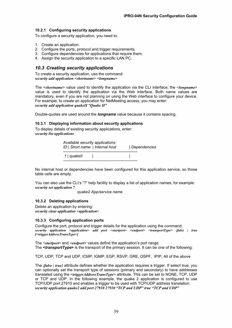
iPRO-04N Security Configuration Guide 10.2.1 Configuring security applications To configure a security application, you need to: 1. Create an application. 2. Configure the ports, protocol and trigger requirements. 3. Configure dependencies for applications that require them. 4. Assign the security application to a specific LAN PC.
10.3 Creating security applications To create a security application, use the command: security add application <shortname> <longname> The <shortname> value used to identify the application via the CLI interface; the <longname> value is used to identify the application via the Web interface. Both name values are mandatory, even if you are not planning on using the Web interface to configure your device. For example, to create an application for NetMeeting access, you may enter: security add application quakeII “Quake II” Double-quotes are used around the longname value because it contains spacing.
10.3.1 Displaying information about security applications To display details of existing security applications, enter: security list applications
Available security applications: ID | Short name | Internal host | Dependencies --------------------------------------------------------- 1 | quakeII | | ---------------------------------------------------------
No internal host or dependencies have been configured for this application service, so those table cells are empty. You can also use the CLI’s “?” help facility to display a list of application names, for example: security set application ?
quake2 App/service name
10.3.2 Deleting applications Delete an application by entering: security clear application <application>
10.3.3 Configuring application ports Configure the port, protocol and trigger details for the application using the command: security application <application> add port <startport> <endport> <transportType> {false | true [<triggerAddressTransType>] The <startport> and <endport> values define the application’s port range. The <transportType> is the transport of the primary session. It can be one of the following: TCP, UDP, TCP and UDP, ICMP, IGMP, EGP, RSVP, GRE, OSPF, IPIP, All of the above The {false | true} attribute defines whether the application requires a trigger. If select true, you can optionally set the transport type of sessions (primary and secondary) to have addresses translated using the <triggerAddressTransType> attribute. This can be set to NONE, TCP, UDP or TCP and UDP. In the following example, the quake 2 application is configured to use TCP/UDP port 27910 and enables a trigger to be used with TCP/UDP address translation: security application quake2 add port 27910 27910 “TCP and UDP” true “TCP and UDP”
39
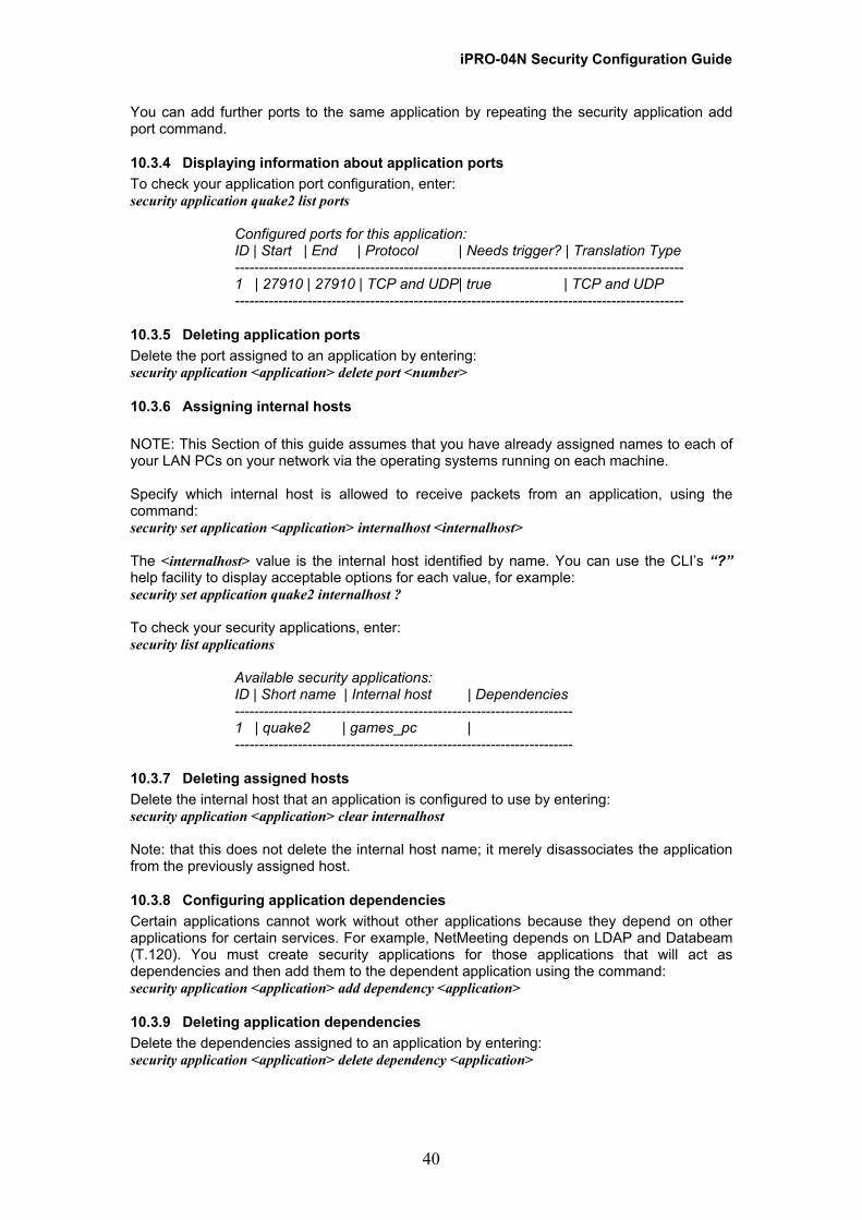
iPRO-04N Security Configuration Guide You can add further ports to the same application by repeating the security application add port command.
10.3.4 Displaying information about application ports To check your application port configuration, enter: security application quake2 list ports
Configured ports for this application: ID | Start | End | Protocol | Needs trigger? | Translation Type --------------------------------------------------------------------------------------------- 1 | 27910 | 27910 | TCP and UDP| true | TCP and UDP ---------------------------------------------------------------------------------------------
10.3.5 Deleting application ports Delete the port assigned to an application by entering: security application <application> delete port <number>
10.3.6 Assigning internal hosts NOTE: This Section of this guide assumes that you have already assigned names to each of your LAN PCs on your network via the operating systems running on each machine. Specify which internal host is allowed to receive packets from an application, using the command: security set application <application> internalhost <internalhost> The <internalhost> value is the internal host identified by name. You can use the CLI’s “?” help facility to display acceptable options for each value, for example: security set application quake2 internalhost ? To check your security applications, enter: security list applications
Available security applications: ID | Short name | Internal host | Dependencies ---------------------------------------------------------------------- 1 | quake2 | games_pc | ----------------------------------------------------------------------
10.3.7 Deleting assigned hosts Delete the internal host that an application is configured to use by entering: security application <application> clear internalhost Note: that this does not delete the internal host name; it merely disassociates the application from the previously assigned host.
10.3.8 Configuring application dependencies Certain applications cannot work without other applications because they depend on other applications for certain services. For example, NetMeeting depends on LDAP and Databeam (T.120). You must create security applications for those applications that will act as dependencies and then add them to the dependent application using the command: security application <application> add dependency <application>
10.3.9 Deleting application dependencies Delete the dependencies assigned to an application by entering: security application <application> delete dependency <application>
40
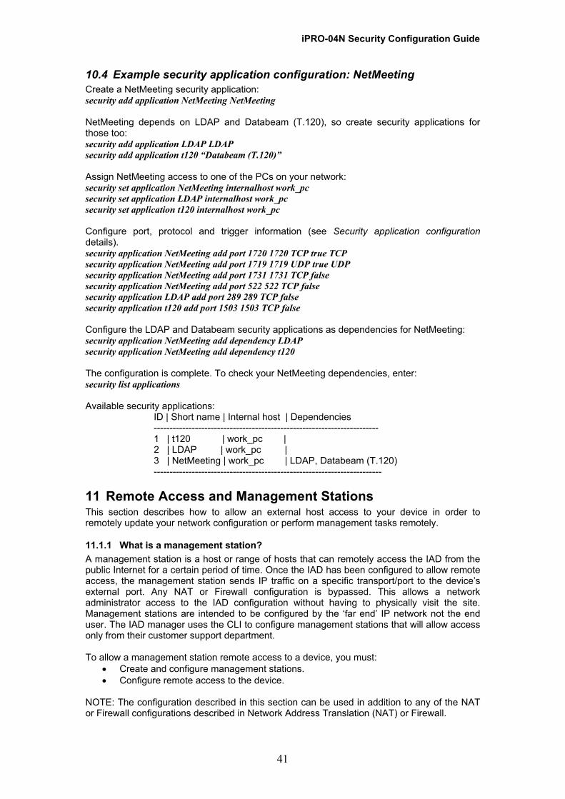
iPRO-04N Security Configuration Guide 10.4 Example security application configuration: NetMeeting Create a NetMeeting security application: security add application NetMeeting NetMeeting NetMeeting depends on LDAP and Databeam (T.120), so create security applications for those too: security add application LDAP LDAP security add application t120 “Databeam (T.120)” Assign NetMeeting access to one of the PCs on your network: security set application NetMeeting internalhost work_pc security set application LDAP internalhost work_pc security set application t120 internalhost work_pc Configure port, protocol and trigger information (see Security application configuration details). security application NetMeeting add port 1720 1720 TCP true TCP security application NetMeeting add port 1719 1719 UDP true UDP security application NetMeeting add port 1731 1731 TCP false security application NetMeeting add port 522 522 TCP false security application LDAP add port 289 289 TCP false security application t120 add port 1503 1503 TCP false Configure the LDAP and Databeam security applications as dependencies for NetMeeting: security application NetMeeting add dependency LDAP security application NetMeeting add dependency t120 The configuration is complete. To check your NetMeeting dependencies, enter: security list applications Available security applications:
ID | Short name | Internal host | Dependencies ----------------------------------------------------------------------- 1 | t120 | work_pc | 2 | LDAP | work_pc | 3 | NetMeeting | work_pc | LDAP, Databeam (T.120) ------------------------------------------------------------------------
11 Remote Access and Management Stations This section describes how to allow an external host access to your device in order to remotely update your network configuration or perform management tasks remotely.
11.1.1 What is a management station? A management station is a host or range of hosts that can remotely access the IAD from the public Internet for a certain period of time. Once the IAD has been configured to allow remote access, the management station sends IP traffic on a specific transport/port to the device’s external port. Any NAT or Firewall configuration is bypassed. This allows a network administrator access to the IAD configuration without having to physically visit the site. Management stations are intended to be configured by the ‘far end’ IP network not the end user. The IAD manager uses the CLI to configure management stations that will allow access only from their customer support department. To allow a management station remote access to a device, you must:
• Create and configure management stations. • Configure remote access to the device.
NOTE: The configuration described in this section can be used in addition to any of the NAT or Firewall configurations described in Network Address Translation (NAT) or Firewall.
41
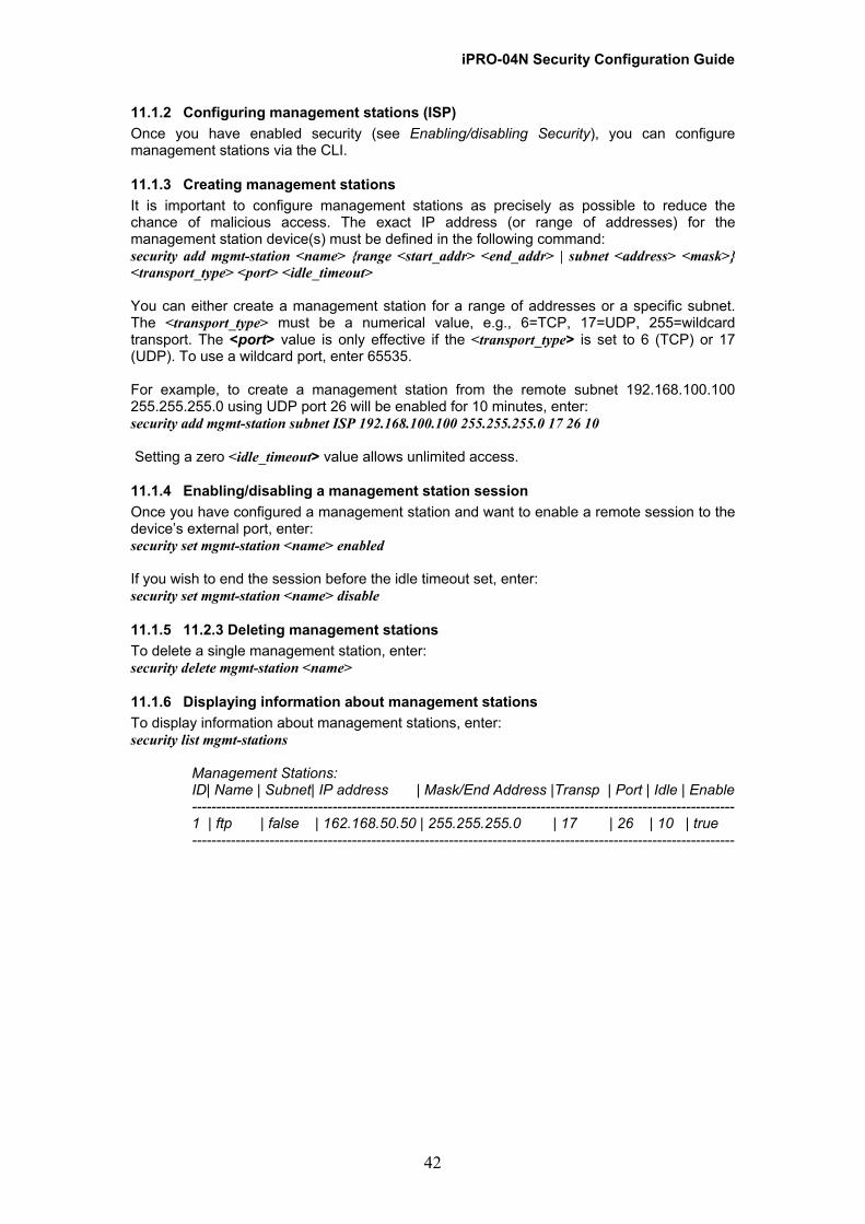
iPRO-04N Security Configuration Guide 11.1.2 Configuring management stations (ISP) Once you have enabled security (see Enabling/disabling Security), you can configure management stations via the CLI.
11.1.3 Creating management stations It is important to configure management stations as precisely as possible to reduce the chance of malicious access. The exact IP address (or range of addresses) for the management station device(s) must be defined in the following command: security add mgmt-station <name> {range <start_addr> <end_addr> | subnet <address> <mask>} <transport_type> <port> <idle_timeout> You can either create a management station for a range of addresses or a specific subnet. The <transport_type> must be a numerical value, e.g., 6=TCP, 17=UDP, 255=wildcard transport. The <port> value is only effective if the <transport_type> is set to 6 (TCP) or 17 (UDP). To use a wildcard port, enter 65535. For example, to create a management station from the remote subnet 192.168.100.100 255.255.255.0 using UDP port 26 will be enabled for 10 minutes, enter: security add mgmt-station subnet ISP 192.168.100.100 255.255.255.0 17 26 10 Setting a zero <idle_timeout> value allows unlimited access.
11.1.4 Enabling/disabling a management station session Once you have configured a management station and want to enable a remote session to the device’s external port, enter: security set mgmt-station <name> enabled If you wish to end the session before the idle timeout set, enter: security set mgmt-station <name> disable
11.1.5 11.2.3 Deleting management stations To delete a single management station, enter: security delete mgmt-station <name>
11.1.6 Displaying information about management stations To display information about management stations, enter: security list mgmt-stations
Management Stations: ID| Name | Subnet| IP address | Mask/End Address |Transp | Port | Idle | Enable ---------------------------------------------------------------------------------------------------------------- 1 | ftp | false | 162.168.50.50 | 255.255.255.0 | 17 | 26 | 10 | true ----------------------------------------------------------------------------------------------------------------
42
iPRO-04N Security Configuration Guide
12 Appendix A Troubleshooting Security A.1 General troubleshooting A.1.1 I’m using the Security package and keep getting ‘not enough resource’ messages. Why? This message is usually because too many sessions have been created. For example, an application like emule may cause this because it creates many sessions. Check the session log to see how many sessions are currently open. A.2 Firewall troubleshooting A.2.1 When I ping the external interface for the WAN side, I get no response. Why? Traffic received on the external interface that was destined for the external interface is handled by the filters for the external-internal policy. If you want the external interface to respond to pings, you must use the firewall add portfilter command to create a filter that allows pings (ICMP) to the external-internal policy. For example: firewall add portfilter ping ext-int icmp both A.2.2 I’ve created an inbound filter. When I try to add an outbound filter for the same protocol, I get an error message. Why? When you add an inbound filter, the protocol/port in the outbound direction is automatically blocked. You cannot create an outbound filter using the same protocol/portnumber as the existing inbound filter. If you want the filter to work in both directions, you need to delete the existing inbound-only filter and create a filter that allows traffic in both directions. For example: firewall add portfilter icmp int-ext icmp inbound firewall add portfilter icmp int-ext icmp outbound Unable to add port filter, entry already exists Error adding port filter icmp-out to policy firewall delete portfilter icmp-out int-ext firewall add portfilter icmp int-ext icmp both A.2.3 I started an http session then enabled the firewall with the security level set to none. I expected http traffic to be blocked but http data still flowed through the firewall. Even after I disabled the firewall, http data continued to flow through the firewall. Why? The Security package uses the concept of session tracking. A session begins as soon as the Security package is enabled, and the session stays open for as long as data continues to flow on it. A session will time out after the session expiry time Even though you enabled the Firewall with filters to block http, traffic was transported because a valid http session already existed. You need to close any existing http sessions before you enable the Firewall. Any http sessions should be started after the Firewall has been enabled. A.3 NAT troubleshooting A.3.1 Why doesn’t RIP work over my NAT-enabled interface? RIP is a routing protocol and routing protocols generally do not work over a NAT enabled interface. You should not be enabling RIP on a NAT gateway because all addresses behind the gateway are private and therefore should not be advertised. A.3.2 How do I use NAT with an unnumbered external IP interface? An unnumbered IP interface uses the IP address of another interface. If you want to use NAT with an unnumbered external interface, you need to set up a global pool on the external interface. See Configuring global pools. A.3.4 How do I know if NAT is working?
43
iPRO-04N Security Configuration Guide
44
You can test if NAT is working by placing a packet sniffer outside the router. The sniffer should show that the IP address of the internal interface has been translated to the IP address of the external interface. A.3.5 I enabled NAT between the external-internal interface, then I added a global pool. When I ping from the internal PC to the external PC, the addresses are not translated to the global pool address. Why? The nat enable command between the external-internal interface created one global IP address on the external interface. The global pool that you explicitly created using the nat add globalpool command means that two global pools exist. When you pinged from the internal PC using the ip ping command, the security software selected one of the global pools to use. In this case, the global pool selected was the one on the external interface created using the nat enable command, so the ping comes from the external IP address and not the global pool that was created later. To configure security so that the global pool created using the nat add globalpool command is the one selected, set up reserved mapping using the wildcard all. For example: nat add resvmap n1 external 192.168.101.1 10.1.1.1 all A.3.6 I created a resvmap to map http data to an inside interface. After I deleted the resvmap, the external host could still see the internal web site. Why? The Security package uses the concept of session tracking. A session begins as soon as the Security package is enabled, and the session stays open for as long as data continues to flow on it. A session will time out after the session expiry time. This is a compile-time setting. A session remains active even if configuration changes are made. If you want to stop access from the external host before the five minute expiry setting, disable then enable NAT between the two interfaces using the nat disable/enable command. A.4 Trigger troubleshooting A.4.1 I started a Quake II session then set up a Quake II trigger, but no data is being transmitted. Why? The Security package uses the concept of session tracking. A session begins as soon as the Security package is enabled, and the session stays open for as long as data continues to flow on it. A session will time out after the session expiry time. This is a compile-time setting. If you have already started a Quake II session then later added a trigger, the Quake II session does not know about the trigger and no data will be transmitted. You need to restart your Quake II session.