data sheet thermostatic expansion valves type t2 / te2 · data sheet thermostatic expansion valves,...
TRANSCRIPT

MAKING MODERN LIVING POSSIBLE
DKRCC.PD.AA0.A6.02 / 520H7000 1
Features Large temperature range Equally applicable to freezing, refrigeration and air conditioning applications.Interchangeable orifice assembly – easy storage – easy capacity matching – better service.Rated capacities from 0.96 to 20.5 kW (0.27 to 5.82 TR) for R407C.
Can be supplied with MOP (Max. Operating Pressure) Protects the compressor motor against excessive evaporating pressure during normal operation.Stainless steel bulb and Danfoss patented bulb strap Fast and easy to install. Good temperature transfer from pipe to bulb.Valves for special temperature ranges can be supplied.Design protected
Thermostatic expansion valves regulate the injection of refrigerant liquid into evaporators.
Injection is controlled by the refrigerant superheat.
Therefore the valves are especially suitable for liquid injection in ”dry“ evaporators where the superheat at the evaporator outlet is proportional to the evaporator load.
Data sheet
Thermostatic expansion valvesType T2 / TE2

Data sheet Thermostatic expansion valves, type T 2 and TE 2
MOP-pointsRefrigerant Range N
–40 °C - +10 °CRange NM
–40 °C - –5 °CRange NL
–40 °C - –15 °CRange B
–60 °C - –25 °C
MOP-point in evaporating temperature te and evaporating pressure pe 1)
+15 °C / +60 °F 0 °C / +32 °F –10 °C / +15 °F –20 °C / –4 °F
R22 100 psig/6.9 bar (abs) 60 psig/4.0 bar (abs) 35 psig/2.4 bar (abs) 20 psig/1.4 bar (abs)
R407C 95 psig/6.6 bar (abs)
R134a 55 psig/3.8 bar (abs) 30 psig/2.0 bar (abs) 15 psig/1.0 bar (abs)
R404A/R507 120 psig/8.3 bar (abs) 75 psig/5.2 bar (abs) 50 psig/3.4 bar (abs) 30 psig/2.1 bar (abs)
DKRCC.PD.AA0.A6.02 / 520H70002
Technical data Max. temperatureBulb, when valve is installed: 100 °CBulb, element not mounted: 60 °C
Min. temperatureT 2 - TE 2: –60 °C
Max. test pressurePT = 38 bar
Max. working pressurePS/MWP = 34 bar
1) Pe in bar gauge
SS = static superheatOS = opening superheatSH = SS + OS = total superheatQnom = rated capacityQmax = maximum capacity
Static superheat SS can be adjusted with setting spindle.
Superheat The standard superheat setting SS is 5 K for valves without MOP and 4 K for valves with MOP.The opening superheat OS is 6 K from when opening begins to where the valve gives its rated capacity Qnom.
ExampleStatic superheat SS = 5 KOpening superheat OS = 6 KTotal superheat SH = 5 + 6 = 11 K
Identification The thermostatic element has laser engraved data on top of the diaphragm. This engraving gives valve type (with code number), evaporating temperature range, MOP point, refrigerant, and max. working pressure. PS/MWP.
The code refers to the refrigerant for which the valve is designed:X = R22/R407C1) Z = R407CN = R134a S = R404A/ R507
Production place and dateN4511A = N = Nordborg, Denmark(BE = Wuqing, China)45 = week11 = 2011A = Monday
1) For R407C plants, please select valves from the dedicated R407C program
Orifice assembly for T 2 and TE 2The orifice assembly is marked with the orifice size (e.g. 06) and week stamp + last number in the year (e.g. 174). The orifice assembly number is also given on the lid of its plastic container.
Capillary tube label for T 2 and TE 2The label gives the orifice size (04) and consists of the lid of the orifice assembly plastic container. It can easily be fastened around the expansion valve capillary tube to clearly identify the valve size.
Orifice assembly and filter for flare x flare versionfor T 2 and TE 2
Capillary tube labelT 2 and TE 2

Data sheet Thermostatic expansion valves, type T 2 and TE 2
4 3
1
2
Dan
foss
68Z0
5.14
.20
T 2
DKRCC.PD.AA0.A6.02 / 520H70003
DesignFunction
GeneralT 2 and TE 2 valves have an interchangeable orifice assembly.
The orifice assembly is suitable for all versions of valve body and refrigerants and in all evaporating temperature ranges. The charge in the thermostatic element depends on the refrigerant and evaporating temperature range.The valves are available with internal (T2) or external (TE2) pressure equalization.
External pressure equalization should always be used on systems with liquid distributors.The bulb gives fast and precise reaction to temperature changes in the evaporator. The bulb is fixed with a Danfoss patented bulb strap for quick, easy and reliable connection. The valves are able to withstand the effects that normally occur with hot gas defrosting.
To ensure long operating life, the valve cone and seat are made of a special alloy with particularly good wear qualities.
1. Thermostatic element (diaphragm) 2. Interchangeable orifice assembly 3. Valve body 4. Superheat setting spindle (see instructions)

Data sheet Thermostatic expansion valves, type T 2 and TE 2
DKRCC.PD.AA0.A6.02 / 520H70004
T2/TE2 Thermostatic element with bulb strapFlare x flare
Capillary tube: 1.5 mRange N = -40 – +10 °CRange B = -60 – -25 °CRange NM = -40 – -5 °C MOP 0 °CRange NL = -40 – -15 °C MOP -10 °C
Refrigerant Type Range MOPPressure
equlizationFlare
Connection flare inlet × outlet Code no.
Multi pack[in.] [mm]
R22/R407C1)
TX 2 -40 – +10 °C – – 3/8 × 1/2 10×12 068Z3206
TX 2 -40 – +10 °C +15 °C – 3/8 × 1/2 10×12 068Z3208
TX 2 -40 – -5 °C 0 °C – 3/8 × 1/2 10×12 068Z3224
TX 2 -40 – -15 °C -10 °C – 3/8 × 1/2 10×12 068Z3226
TX 2 -60 – -25 °C – – 3/8 × 1/2 10×12 068Z3207
TX 2 -60 – -25 °C -20 °C – 3/8 × 1/2 10×12 068Z3228
TEX 2 -40 – +10 °C – ¼ in. 3/8 × 1/2 10×12 068Z3209
TEX 2 -40 – +10 °C +15 °C ¼ in. 3/8 × 1/2 10×12 068Z3211
TEX 2 -40 – -5 °C 0 °C ¼ in. 3/8 × 1/2 10×12 068Z3225
TEX 2 -40 – -15 °C -10 °C ¼ in. 3/8 × 1/2 10×12 068Z3227
TEX 2 -60 – -25 °C – ¼ in. 3/8 × 1/2 10×12 068Z3210
TEX 2 -60 – -25 °C -20 °C ¼ in. 3/8 × 1/2 10×12 068Z3229
R407C
TZ 2 -40 – +10 °C – – 3/8 × 1/2 10×12 068Z3496
TZ 2 -40 – +10 °C +15 °C – 3/8 × 1/2 10×12 068Z3516
TEZ 2 -40 – +10 °C – ¼ in. 3/8 × 1/2 10×12 068Z3501
TEZ 2 -40 – +10 °C +15 °C ¼ in. 3/8 × 1/2 10×12 068Z3517
R134a
TN 2 -40 – +10 °C – – 3/8 × 1/2 10×12 068Z3346
TN 2 -40 – +10 °C +15 °C – 3/8 × 1/2 10×12 068Z3347
TN 2 -40 – -5 °C 0 °C – 3/8 × 1/2 10×12 068Z3393
TN 2 -40 – -15 °C -10 °C – 3/8 × 1/2 10×12 068Z3369
TEN 2 -40 – +10 °C – ¼ in. 3/8 × 1/2 10×12 068Z3348
TEN 2 -40 – +10 °C +15 °C ¼ in. 3/8 × 1/2 10×12 068Z3349
TEN 2 -40 – -5 °C 0 °C ¼ in. 3/8 × 1/2 10×12 068Z3392
TEN 2 -40 – -15 °C -10 °C ¼ in. 3/8 × 1/2 10×12 068Z3370
R404A/R507
TS 2 -40 – +10 °C – – 3/8 × 1/2 10×12 068Z3400
TS 2 -40 – +10 °C +15 °C – 3/8 × 1/2 10×12 068Z3402
TS 2 -40 – -5 °C 0 °C – 3/8 × 1/2 10×12 068Z3406
TS 2 -40 – -15 °C -10 °C – 3/8 × 1/2 10×12 068Z3408
TS 2 -60 – -25 °C – – 3/8 × 1/2 10×12 068Z3401
TS 2 -60 – -25 °C -20 °C – 3/8 × 1/2 10×12 068Z3410
TES 2 -40 – +10 °C – ¼ in. 3/8 × 1/2 10×12 068Z3403
TES 2 -40 – +10 °C +15 °C ¼ in. 3/8 × 1/2 10×12 068Z3405
TES 2 -40 – -5 °C 0 °C ¼ in. 3/8 × 1/2 10×12 068Z3407
TES 2 -40 – -15 °C -10 °C ¼ in. 3/8 × 1/2 10×12 068Z3409
TES 2 -60 – -25 °C – ¼ in. 3/8 × 1/2 10×12 068Z3404
TES 2 -60 – -25 °C -20 °C ¼ in. 3/8 × 1/2 10×12 068Z3411
R407F/R407AT2 -40 – +10 °C – – 3/8 × 1/2 10×12 068Z3715
TE2 -40 – +10 °C – ¼ in. 3/8 × 1/2 10×12 068Z37141) For R407C plants. Please select valves from the dedicated R407C program
Technical data and ordering

Data sheet Thermostatic expansion valves, type T 2 and TE 2
DKRCC.PD.AA0.A6.02 / 520H70005
T2/TE2 Thermostatic element with bulb strapFlare x solder
Capillary tube: 1.5 mRange N = -40 – +10 °CRange NL = -40 – -15 °CRange B = -60 – -25 °C
Refrigerant Type Range MOPPressure
equalizationsolder
Connection inlet (Flare) × outlet (Solder) Code no.
Multi pack[in.] [mm]
R22/R407C 1)
TX 2 -40 – +10 °C – – 3/8 × 1/2 – 068Z3281TX 2 -40 – +10 °C – – – 10×12 068Z3302TX 2 -40 – +10 °C +15 °C – 3/8 × 1/2 – 068Z3287TX 2 -40 – +10 °C +15 °C – – 10×12 068Z3308TX 2 -40 – -15 °C -10 °C – – 10×12 068Z3366TX 2 -60 – -25 °C – – 3/8 × 1/2 – 068Z3357TX 2 -60 – -25 °C – – – 10×12 068Z3361TX 2 -60 – -25 °C -20 °C – 3/8 × 1/2 – 068Z3319
TEX 2 -40 – +10 °C – ¼ in. 3/8 × 1/2 – 068Z3284TEX 2 -40 – +10 °C – 6 mm – 10×12 068Z3305TEX 2 -40 – +10 °C +15 °C ¼ in. 3/8 × 1/2 – 068Z3290TEX 2 -40 – +10 °C +15 °C 6 mm – 10×12 068Z3311TEX 2 -40 – -15 °C -10 °C 6 mm – 10×12 068Z3367TEX 2 -60 – -25 °C – ¼ in. 3/8 × 1/2 – 068Z3359TEX 2 -60 – -25 °C – 6 mm – 10×12 068Z3363TEX 2 -60 – -25 °C -20 °C – 3/8 × 1/2 – 068Z3320
R407C
TZ 2 -40 – +10 °C – – – 10×12 068Z3502TZ 2 -40 – +10 °C +15 °C – 3/8 × 1/2 – 068Z3329TZ 2 -40 – +10 °C +15 °C – – 10×12 068Z3514
TEZ 2 -40 – +10 °C – ¼ in. 3/8 × 1/21/2 in. 068Z3446
TEZ 2 -40 – +10 °C – 6 mm – 10×12 068Z3503TEZ 2 -40 – +10 °C +15 °C ¼ in. 3/8 × 1/2 – 068Z3447TEZ 2 -40 – +10 °C +15 °C 6 mm – 10×12 068Z3515
R134a
TN 2 -40 – +10 °C – – 3/8 × 1/2 – 068Z3383TN 2 -40 – +10 °C – – – 10×12 068Z3384TN 2 -40 – +10 °C +15 °C – 3/8 × 1/2 – 068Z3387TN 2 -40 – +10 °C +15 °C – – 10×12 068Z3388
TEN 2 -40 – +10 °C – ¼ in. 3/8 × 1/2 – 068Z3385TEN 2 -40 – +10 °C – 6 mm – 10×12 068Z3386TEN 2 -40 – +10 °C +15 °C ¼ in. 3/8 × 1/2 – 068Z3389TEN 2 -40 – +10 °C +15 °C 6 mm – 10×12 068Z3390
R404A/R507
TS 2 -40 – +10 °C – – 3/8 × 1/2 – 068Z3414TS 2 -40 – +10 °C – – – 10×12 068Z3435TS 2 -40 – +10 °C +15 °C – 3/8 × 1/2 – 068Z3416TS 2 -40 – +10 °C +15 °C – – 10×12 068Z3423TS 2 -40 – -15 °C -10 °C – 3/8 × 1/2 – 068Z3429TS 2 -40 – -15 °C -10 °C – – 10×12 068Z3436TS 2 -60 – -25 °C – – 3/8 × 1/2 – 068Z3418TS 2 -60 – -25 °C – – – 10×12 068Z3425TS 2 -60 – -25 °C -20 °C – 3/8 × 1/2 – 068Z3420TS 2 -60 – -25 °C -20 °C – – 10×12 068Z3427
TES 2 -40 – +10 °C – ¼ in. 3/8 × 1/2 – 068Z3415TES 2 -40 – +10 °C – 6 mm – 10×12 068Z3422TES 2 -40 – +10 °C +15 °C 6 mm – 10×12 068Z3424TES 2 -40 – +10 °C +15 °C ¼ in. 3/8 × 1/2 – 068Z3417TES 2 -40 – -15 °C -10 °C ¼ in. 3/8 × 1/2 – 068Z3430TES 2 -40 – -15 °C -10 °C 6 mm – 10×12 068Z3437TES 2 -60 – -25 °C – ¼ in. 3/8 × 1/2 – 068Z3419TES 2 -60 – -25 °C – 6 mm – 10×12 068Z3426TES 2 -60 – -25 °C -20 °C ¼ in. 3/8 × 1/2 – 068Z3421TES 2 -60 – -25 °C -20 °C 6 mm – 10×12 068Z3428
R407F/ R407AT2 -40 – +10 °C – – 3/8 × 1/2 – 068Z3716
TE2 -40 – +10 °C – ¼ in. 3/8 × 1/2 – 068Z37131) For R407C plants, please select valves from the dedicated R407C program
Technical data and ordering
Data sheet Thermostatic expansion valves, type T 2 and TE 2
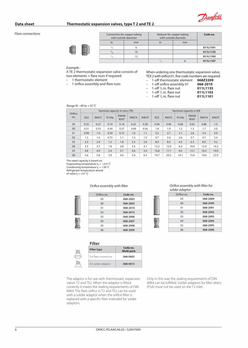
Connection for copper tubingwith outside diameter
Reducer for copper tubingwith outside diameter
Code no.
in. mm in. mm1/4 6 011L11013/8 10 011L11351/2 12 011L1103
1/4 6 011L1107
Range N: –40 to +10 °C
Orifice no.
Nominal capacity in tons (TR) Nominal capacity in kW
R22 R407C R134a R404AR507 R407A R407F R22 R407C R134a R404A
R507 R407A R407F
0X 0.25 0.27 0.19 0.18 0.25 0.28 0.90 0.96 0.68 0.65 0.88 1.0
00 0.51 0.53 0.34 0.37 0.49 0.56 1.8 1.9 1.2 1.3 1.7 2.0
01 0.99 1.0 0.59 0.75 1.0 1.1 3.5 3.7 2.1 2.6 3.4 3.9
02 1.3 1.4 0.73 1.1 1.3 1.5 4.7 5.0 2.6 3.7 4.7 5.4
03 2.3 2.4 1.2 1.8 2.3 2.6 8.0 8.5 4.3 6.3 8.0 9.2
04 3.5 3.7 1.8 2.8 3.5 4.1 12.2 12.9 6.4 10.0 12.4 14.3
05 4.8 4.9 2.4 3.7 4.6 5.4 16.8 17.1 8.4 13.1 16.3 19.0
06 5.6 5.8 2.9 4.4 5.6 6.5 19.7 20.5 10.1 15.6 19.6 22.9
Orifice assembly with filter forsolder adaptor
Orifice no. Code no.
0X 068-2089
00 068-2090
01 068-2091
02 068-2092
03 068-2093
04 068-2094
05 068-2095
06 068-2096
Orifice assembly with filter
Orifice no. Code no.
0X 068-2002
00 068-2003
01 068-2010
02 068-2015
03 068-2006
04 068-2007
05 068-2008
06 068-2009
DKRCC.PD.AA0.A6.02 / 520H70006
Flare connections
Example :A TE 2 thermostatic expansion valve consists of two elements + flare nuts if required:– 1 thermostatic element– 1 orifice assembly and flare nuts
When ordering one thermostatic expansion valve, TEX 2 with orifice 01, five code numbers are required:– 1-off thermostatic element 068Z3209– 1-off orifice assembly 01 068-2010– 1-off 3⁄8 in. flare nut 011L1135– 1-off 1⁄2 in. flare nut 011L1103– 1-off 1⁄4 in. flare nut 011L1101
The rated capacity is based on:Evaporating temperature te = +4.4 °CCondensing temperature tc = +38 °CRefrigerant temperature ahead of valve tl = +37 °C
Dan
foss
68Z6
2.11
FilterFilter type Code no.
Multi pack
For flare connection 068-0003
For solder adaptor 068-0015
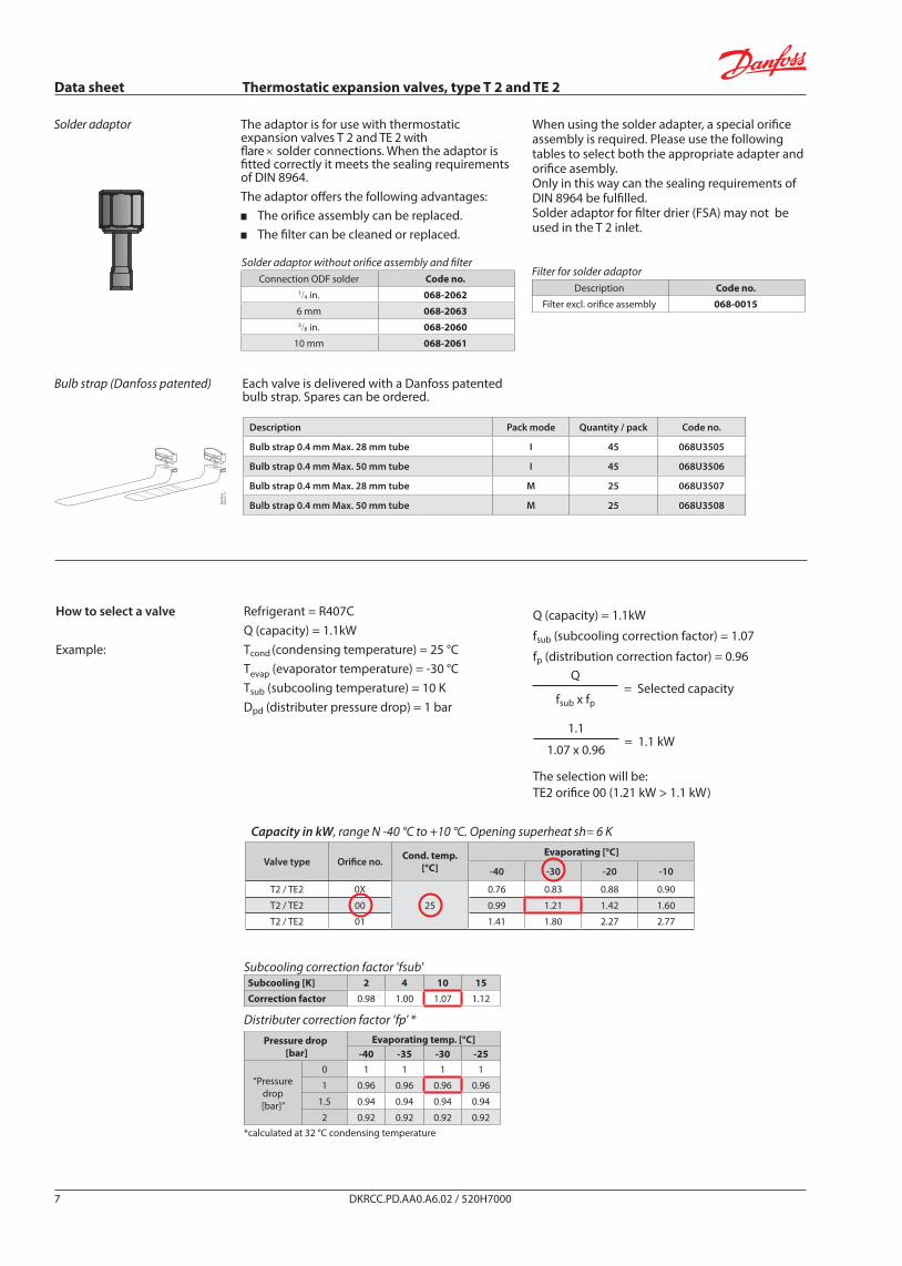
The adaptor is for use with thermostatic expansion valves T2 and TE2. When the adaptor is fitted correctly it meets the sealing requirements of DIN 8964. The flare orifice in T2 and TE2 can be used with a solder adaptor when the orifice filter is replaced with a specific filter intended for solder adaptors.
Only in this way the sealing requirements of DIN 8964 can be fulfilled. Solder adaptors for filter driers (FSA) must not be used on the T2 inlet.
Data sheet Thermostatic expansion valves, type T 2 and TE 2
Refrigerant = R407CQ (capacity) = 1.1kWTcond (condensing temperature) = 25 °CTevap (evaporator temperature) = -30 °CTsub (subcooling temperature) = 10 KDpd (distributer pressure drop) = 1 bar
Q (capacity) = 1.1kW
fsub (subcooling correction factor) = 1.07
fp (distribution correction factor) = 0.96Q
= Selected capacityfsub x fp
1.1
= 1.1 kW1.07 x 0.96
The selection will be:TE2 orifice 00 (1.21 kW > 1.1 kW)
How to select a valve
Example:
Capacity in kW, range N -40 °C to +10 °C. Opening superheat sh= 6 K
Valve type Orifice no. Cond. temp.[°C]
Evaporating [°C]
-40 -30 -20 -10
T2 / TE2 0X
25
0.76 0.83 0.88 0.90
T2 / TE2 00 0.99 1.21 1.42 1.60
T2 / TE2 01 1.41 1.80 2.27 2.77
Description Pack mode Quantity / pack Code no.
Bulb strap 0.4 mm Max. 28 mm tube I 45 068U3505
Bulb strap 0.4 mm Max. 50 mm tube I 45 068U3506
Bulb strap 0.4 mm Max. 28 mm tube M 25 068U3507
Bulb strap 0.4 mm Max. 50 mm tube M 25 068U3508
Solder adaptor without orifice assembly and filterConnection ODF solder Code no.
1/4 in. 068-2062
6 mm 068-20633/8 in. 068-2060
10 mm 068-2061
DKRCC.PD.AA0.A6.02 / 520H70007
Subcooling correction factor 'fsub'Subcooling [K] 2 4 10 15Correction factor 0.98 1.00 1.07 1.12
Distributer correction factor 'fp' *
Pressure drop [bar]
Evaporating temp. [°C]-40 -35 -30 -25
“Pressure drop [bar]”
0 1 1 1 1
1 0.96 0.96 0.96 0.96
1.5 0.94 0.94 0.94 0.94
2 0.92 0.92 0.92 0.92*calculated at 32 °C condensing temperature
Each valve is delivered with a Danfoss patented bulb strap. Spares can be ordered.
Bulb strap (Danfoss patented)
The adaptor is for use with thermostatic expansion valves T 2 and TE 2 with flare × solder connections. When the adaptor is fitted correctly it meets the sealing requirements of DIN 8964.The adaptor offers the following advantages:
The orifice assembly can be replaced.The filter can be cleaned or replaced.
When using the solder adapter, a special orifice assembly is required. Please use the following tables to select both the appropriate adapter and orifice asembly.Only in this way can the sealing requirements of DIN 8964 be fulfilled.Solder adaptor for filter drier (FSA) may not be used in the T 2 inlet.
Solder adaptor
Filter for solder adaptorDescription Code no.
Filter excl. orifice assembly 068-0015

Data sheet Thermostatic expansion valves, type T 2 and TE 2
Capacity in kW, range N -40 °C to +10 °C. Opening superheat sh= 6 K R22Valve type Orifice no. Cond. temp.
[°C]
Evaporating [°C]
-40 -30 -20 -10 0 10
Capacity [kW]
T2 / TE2 0X
25
0.75 0.82 0.86 0.86 0.81 0.68
T2 / TE2 00 0.95 1.18 1.39 1.53 1.55 1.37
T2 / TE2 01 1.32 1.72 2.18 2.63 2.91 2.78
T2 / TE2 02 1.49 1.98 2.57 3.24 3.82 3.88
T2 / TE2 03 2.49 3.32 4.32 5.43 6.40 6.57
T2 / TE2 04 3.59 4.79 6.35 8.16 9.72 9.88
T2 / TE2 05 4.69 6.25 8.30 10.80 13.10 13.50
T2 / TE2 06 5.53 7.36 9.73 12.70 15.40 16.00
Valve type Orifice no. Cond. temp.[°C]
Evaporating [°C]
-40 -30 -20 -10 0 10
Capacity [kW]
T2 / TE2 0X
35
0.78 0.86 0.91 0.93 0.92 0.85
T2 / TE2 00 0.99 1.23 1.47 1.67 1.77 1.72
T2 / TE2 01 1.37 1.80 2.31 2.86 3.33 3.50
T2 / TE2 02 1.56 2.08 2.74 3.54 4.38 4.92
T2 / TE2 03 2.62 3.51 4.62 5.96 7.39 8.35
T2 / TE2 04 3.85 5.12 6.83 8.98 11.20 12.70
T2 / TE2 05 5.03 6.68 8.93 11.90 15.30 17.50
T2 / TE2 06 5.89 7.82 10.40 13.90 17.90 20.70
Valve type Orifice no. Cond. temp.[°C]
Evaporating [°C]
-40 -30 -20 -10 0 10
Capacity [kW]
T2 / TE2 0X
45
0.80 0.88 0.94 0.97 0.98 0.95
T2 / TE2 00 1.01 1.26 1.52 1.75 1.90 1.94
T2 / TE2 01 1.41 1.85 2.39 3.00 3.59 3.96
T2 / TE2 02 1.61 2.14 2.84 3.72 4.74 5.60
T2 / TE2 03 2.71 3.64 4.82 6.32 8.08 9.63
T2 / TE2 04 4.06 5.37 7.14 9.47 12.20 14.50
T2 / TE2 05 5.30 7.01 9.37 12.60 16.70 20.30
T2 / TE2 06 6.19 8.18 10.90 14.70 19.50 24.00
Valve type Orifice no. Cond. temp.[°C]
Evaporating [°C]
-40 -30 -20 -10 0 10
Capacity [kW]
T2 / TE2 0X
55
0.79 0.88 0.94 0.98 1.00 0.99
T2 / TE2 00 1.01 1.26 1.53 1.77 1.95 2.04
T2 / TE2 01 1.42 1.87 2.42 3.06 3.71 4.19
T2 / TE2 02 1.63 2.18 2.89 3.81 4.92 5.95
T2 / TE2 03 2.76 3.70 4.93 6.51 8.46 10.30
T2 / TE2 04 4.23 5.53 7.32 9.68 12.50 15.30
T2 / TE2 05 5.52 7.24 9.64 13.00 17.30 21.70
T2 / TE2 06 6.42 8.43 11.20 15.10 20.30 25.80
Capacity
DKRCC.PD.AA0.A6.02 / 520H70008
Subcooling correction factor 'fsub'Subcooling [K] 2 4 10 15 20 25 30 35 40 45 50Correction factor 0.98 1.00 1.05 1.10 1.14 1.19 1.23 1.28 1.32 1.36 1.41
Distributer correction factor 'fp' *Pressure drop
[bar]Evaporating temp. [°C]
-40 -35 -30 -25 -20 -15 -10 -5 0 5 10 15
“Pressure drop [bar]”
0 1 1 1 1 1 1 1 1 1 1 1 1
1 0.96 0.95 0.95 0.95 0.95 0.95 0.94 0.94 0.93 0.92 0.91 0.89
1.5 0.93 0.93 0.93 0.93 0.92 0.92 0.91 0.91 0.90 0.88 0.86 0.82
2 0.91 0.91 0.90 0.90 0.90 0.89 0.88 0.87 0.86 0.84 0.81 0.76*calculated at 32 °C condensing temperature
Data sheet Thermostatic expansion valves, type T 2 and TE 2
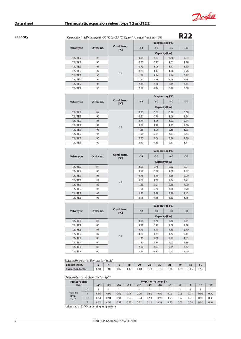
Capacity in kW, range B -60 °C to -25 °C. Opening superheat sh= 6 K R22Valve type Orifice no. Cond. temp.
[°C]
Evaporating [°C]
-60 -50 -40 -30
Capacity [kW]
T2 / TE2 0X
25
0.54 0.67 0.78 0.84
T2 / TE2 00 0.55 0.77 1.03 1.28
T2 / TE2 01 0.72 1.06 1.47 1.95
T2 / TE2 02 0.80 1.17 1.66 2.26
T2 / TE2 03 1.32 1.94 2.76 3.77
T2 / TE2 04 1.87 2.76 3.95 5.45
T2 / TE2 05 2.45 3.60 5.15 7.14
T2 / TE2 06 2.91 4.26 6.10 8.50
Valve type Orifice no. Cond. temp.[°C]
Evaporating [°C]
-60 -50 -40 -30
Capacity [kW]
T2 / TE2 0X
35
0.56 0.69 0.80 0.88
T2 / TE2 00 0.56 0.79 1.06 1.34
T2 / TE2 01 0.74 1.08 1.52 2.04
T2 / TE2 02 0.82 1.20 1.72 2.36
T2 / TE2 03 1.35 1.99 2.85 3.93
T2 / TE2 04 1.90 2.81 4.04 5.63
T2 / TE2 05 2.50 3.66 5.26 7.36
T2 / TE2 06 2.96 4.33 6.21 8.71
Valve type Orifice no. Cond. temp.[°C]
Evaporating [°C]
-60 -50 -40 -30
Capacity [kW]
T2 / TE2 0X
45
0.56 0.70 0.82 0.91
T2 / TE2 00 0.57 0.80 1.08 1.37
T2 / TE2 01 0.75 1.10 1.55 2.09
T2 / TE2 02 0.82 1.22 1.74 2.41
T2 / TE2 03 1.36 2.01 2.88 4.00
T2 / TE2 04 1.91 2.82 4.06 5.70
T2 / TE2 05 2.52 3.68 5.29 7.42
T2 / TE2 06 2.98 4.35 6.23 8.75
Valve type Orifice no. Cond. temp.[°C]
Evaporating [°C]
-60 -50 -40 -30
Capacity [kW]
T2 / TE2 0X
55
0.56 0.70 0.82 0.91
T2 / TE2 00 0.57 0.80 1.08 1.38
T2 / TE2 01 0.75 1.10 1.55 2.10
T2 / TE2 02 0.82 1.21 1.74 2.41
T2 / TE2 03 1.36 2.00 2.87 4.01
T2 / TE2 04 1.89 2.79 4.03 5.66
T2 / TE2 05 2.52 3.67 5.25 7.37
T2 / TE2 06 2.98 4.32 6.17 8.66
Capacity
DKRCC.PD.AA0.A6.02 / 520H70009
Subcooling correction factor 'fsub'Subcooling [K] 2 4 10 15 20 25 30 35 40 45 50Correction factor 0.98 1.00 1.07 1.12 1.18 1.23 1.28 1.34 1.39 1.45 1.50
Distributer correction factor 'fp' *Pressure drop
[bar]Evaporating temp. [°C]
-40 -35 -30 -25 -20 -15 -10 -5 0 5 10 15
“Pressure drop [bar]”
0 1 1 1 1 1 1 1 1 1 1 1 1
1 0.96 0.96 0.96 0.96 0.96 0.96 0.95 0.95 0.95 0.94 0.93 0.92
1.5 0.94 0.94 0.94 0.94 0.94 0.93 0.93 0.93 0.92 0.91 0.90 0.88
2 0.92 0.92 0.92 0.92 0.91 0.91 0.91 0.90 0.89 0.88 0.86 0.84*calculated at 32 °C condensing temperature
Data sheet Thermostatic expansion valves, type T 2 and TE 2
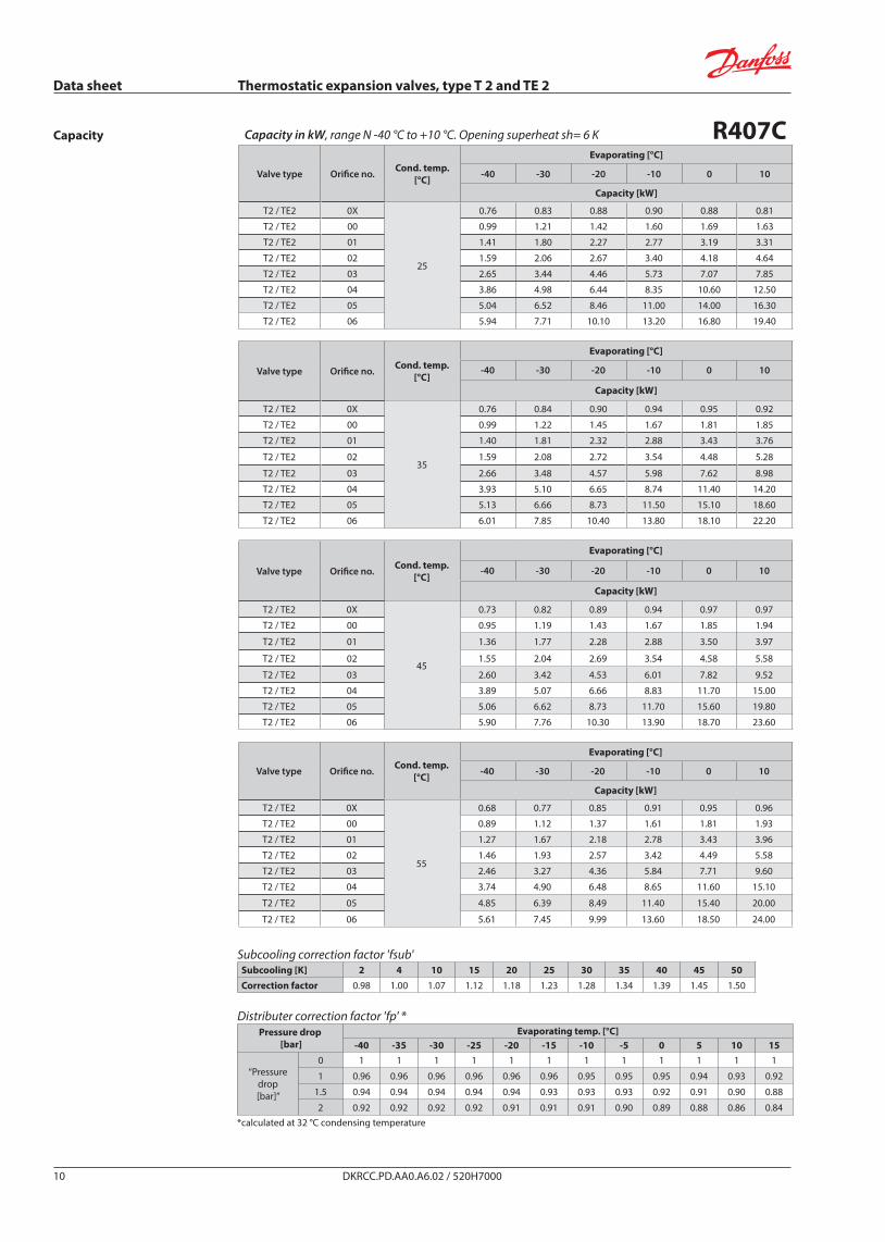
Capacity in kW, range N -40 °C to +10 °C. Opening superheat sh= 6 K R407CValve type Orifice no. Cond. temp.
[°C]
Evaporating [°C]
-40 -30 -20 -10 0 10
Capacity [kW]
T2 / TE2 0X
25
0.76 0.83 0.88 0.90 0.88 0.81
T2 / TE2 00 0.99 1.21 1.42 1.60 1.69 1.63
T2 / TE2 01 1.41 1.80 2.27 2.77 3.19 3.31
T2 / TE2 02 1.59 2.06 2.67 3.40 4.18 4.64
T2 / TE2 03 2.65 3.44 4.46 5.73 7.07 7.85
T2 / TE2 04 3.86 4.98 6.44 8.35 10.60 12.50
T2 / TE2 05 5.04 6.52 8.46 11.00 14.00 16.30
T2 / TE2 06 5.94 7.71 10.10 13.20 16.80 19.40
Valve type Orifice no. Cond. temp.[°C]
Evaporating [°C]
-40 -30 -20 -10 0 10
Capacity [kW]
T2 / TE2 0X
35
0.76 0.84 0.90 0.94 0.95 0.92
T2 / TE2 00 0.99 1.22 1.45 1.67 1.81 1.85
T2 / TE2 01 1.40 1.81 2.32 2.88 3.43 3.76
T2 / TE2 02 1.59 2.08 2.72 3.54 4.48 5.28
T2 / TE2 03 2.66 3.48 4.57 5.98 7.62 8.98
T2 / TE2 04 3.93 5.10 6.65 8.74 11.40 14.20
T2 / TE2 05 5.13 6.66 8.73 11.50 15.10 18.60
T2 / TE2 06 6.01 7.85 10.40 13.80 18.10 22.20
Valve type Orifice no. Cond. temp.[°C]
Evaporating [°C]
-40 -30 -20 -10 0 10
Capacity [kW]
T2 / TE2 0X
45
0.73 0.82 0.89 0.94 0.97 0.97
T2 / TE2 00 0.95 1.19 1.43 1.67 1.85 1.94
T2 / TE2 01 1.36 1.77 2.28 2.88 3.50 3.97
T2 / TE2 02 1.55 2.04 2.69 3.54 4.58 5.58
T2 / TE2 03 2.60 3.42 4.53 6.01 7.82 9.52
T2 / TE2 04 3.89 5.07 6.66 8.83 11.70 15.00
T2 / TE2 05 5.06 6.62 8.73 11.70 15.60 19.80
T2 / TE2 06 5.90 7.76 10.30 13.90 18.70 23.60
Valve type Orifice no. Cond. temp.[°C]
Evaporating [°C]
-40 -30 -20 -10 0 10
Capacity [kW]
T2 / TE2 0X
55
0.68 0.77 0.85 0.91 0.95 0.96
T2 / TE2 00 0.89 1.12 1.37 1.61 1.81 1.93
T2 / TE2 01 1.27 1.67 2.18 2.78 3.43 3.96
T2 / TE2 02 1.46 1.93 2.57 3.42 4.49 5.58
T2 / TE2 03 2.46 3.27 4.36 5.84 7.71 9.60
T2 / TE2 04 3.74 4.90 6.48 8.65 11.60 15.10
T2 / TE2 05 4.85 6.39 8.49 11.40 15.40 20.00
T2 / TE2 06 5.61 7.45 9.99 13.60 18.50 24.00
Capacity
DKRCC.PD.AA0.A6.02 / 520H700010
Subcooling correction factor 'fsub'Subcooling [K] 2 4 10 15 20 25 30 35 40 45 50Correction factor 0.98 1.00 1.07 1.12 1.18 1.23 1.28 1.34 1.39 1.45 1.50
Distributer correction factor 'fp' *Pressure drop
[bar]Evaporating temp. [°C]
-40 -35 -30 -25 -20 -15 -10 -5 0 5 10 15
“Pressure drop [bar]”
0 1 1 1 1 1 1 1 1 1 1 1 1
1 0.96 0.96 0.96 0.96 0.96 0.96 0.95 0.95 0.95 0.94 0.93 0.92
1.5 0.94 0.94 0.94 0.94 0.94 0.93 0.93 0.93 0.92 0.91 0.90 0.88
2 0.92 0.92 0.92 0.92 0.91 0.91 0.91 0.90 0.89 0.88 0.86 0.84*calculated at 32 °C condensing temperature

Data sheet Thermostatic expansion valves, type T 2 and TE 2
Capacity in kW, range N -40 °C to +10 °C. Opening superheat sh= 6 K R134aValve type Orifice no. Cond. temp.
[°C]
Evaporating [°C]
-40 -30 -20 -10 0 10
Capacity [kW]
T2 / TE2 0X
25
0.48 0.54 0.59 0.62 0.61 0.54
T2 / TE2 00 0.52 0.67 0.82 0.95 1.03 0.98
T2 / TE2 01 0.70 0.92 1.19 1.48 1.72 1.77
T2 / TE2 02 0.78 1.03 1.35 1.73 2.08 2.24
T2 / TE2 03 1.31 1.72 2.27 2.89 3.49 3.76
T2 / TE2 04 1.89 2.49 3.28 4.21 5.15 5.69
T2 / TE2 05 2.50 3.28 4.33 5.57 6.80 7.48
T2 / TE2 06 2.98 3.93 5.20 6.69 8.16 8.96
Valve type Orifice no. Cond. temp.[°C]
Evaporating [°C]
-40 -30 -20 -10 0 10
Capacity [kW]
T2 / TE2 0X
35
0.49 0.57 0.63 0.67 0.69 0.66
T2 / TE2 00 0.54 0.69 0.86 1.03 1.17 1.22
T2 / TE2 01 0.72 0.96 1.25 1.60 1.95 2.20
T2 / TE2 02 0.81 1.07 1.43 1.87 2.36 2.79
T2 / TE2 03 1.36 1.80 2.40 3.14 3.96 4.69
T2 / TE2 04 2.02 2.64 3.51 4.60 5.85 7.07
T2 / TE2 05 2.66 3.48 4.62 6.06 7.72 9.31
T2 / TE2 06 3.15 4.14 5.51 7.24 9.24 11.10
Valve type Orifice no. Cond. temp.[°C]
Evaporating [°C]
-40 -30 -20 -10 0 10
Capacity [kW]
T2 / TE2 0X
45
0.49 0.57 0.64 0.69 0.73 0.74
T2 / TE2 00 0.54 0.70 0.88 1.07 1.25 1.36
T2 / TE2 01 0.73 0.97 1.28 1.66 2.08 2.46
T2 / TE2 02 0.82 1.09 1.46 1.93 2.51 3.11
T2 / TE2 03 1.38 1.83 2.45 3.25 4.22 5.24
T2 / TE2 04 2.10 2.73 3.63 4.80 6.24 7.89
T2 / TE2 05 2.76 3.59 4.76 6.31 8.23 10.40
T2 / TE2 06 3.25 4.24 5.64 7.51 9.82 12.40
Valve type Orifice no. Cond. temp.[°C]
Evaporating [°C]
-40 -30 -20 -10 0 10
Capacity [kW]
T2 / TE2 0X
55
0.47 0.56 0.63 0.69 0.74 0.76
T2 / TE2 00 0.53 0.69 0.87 1.07 1.27 1.43
T2 / TE2 01 0.72 0.95 1.26 1.65 2.11 2.57
T2 / TE2 02 0.81 1.08 1.45 1.94 2.55 3.24
T2 / TE2 03 1.38 1.82 2.44 3.27 4.30 5.50
T2 / TE2 04 2.14 2.77 3.66 4.85 6.38 8.25
T2 / TE2 05 2.81 3.63 4.80 6.37 8.40 10.90
T2 / TE2 06 3.30 4.26 5.65 7.54 10.00 13.00
Capacity
DKRCC.PD.AA0.A6.02 / 520H700011
Subcooling correction factor 'fsub'Subcooling [K] 2 4 10 15 20 25 30 35 40 45 50Correction factor 0.98 1.00 1.07 1.12 1.18 1.23 1.29 1.34 1.40 1.45 1.50
Distributer correction factor 'fp' *Pressure drop
[bar]Evaporating temp. [°C]
-40 -35 -30 -25 -20 -15 -10 -5 0 5 10 15
“Pressure drop [bar]”
0 1 1 1 1 1 1 1 1 1 1 1 1
1 0.93 0.93 0.93 0.93 0.92 0.92 0.92 0.91 0.90 0.89 0.87 0.83
1.5 0.90 0.89 0.89 0.89 0.88 0.88 0.87 0.86 0.84 0.82 0.79 0.74
2 0.86 0.86 0.85 0.85 0.84 0.83 0.82 0.81 0.79 0.76 0.71 0.62*calculated at 32 °C condensing temperature
Data sheet Thermostatic expansion valves, type T 2 and TE 2
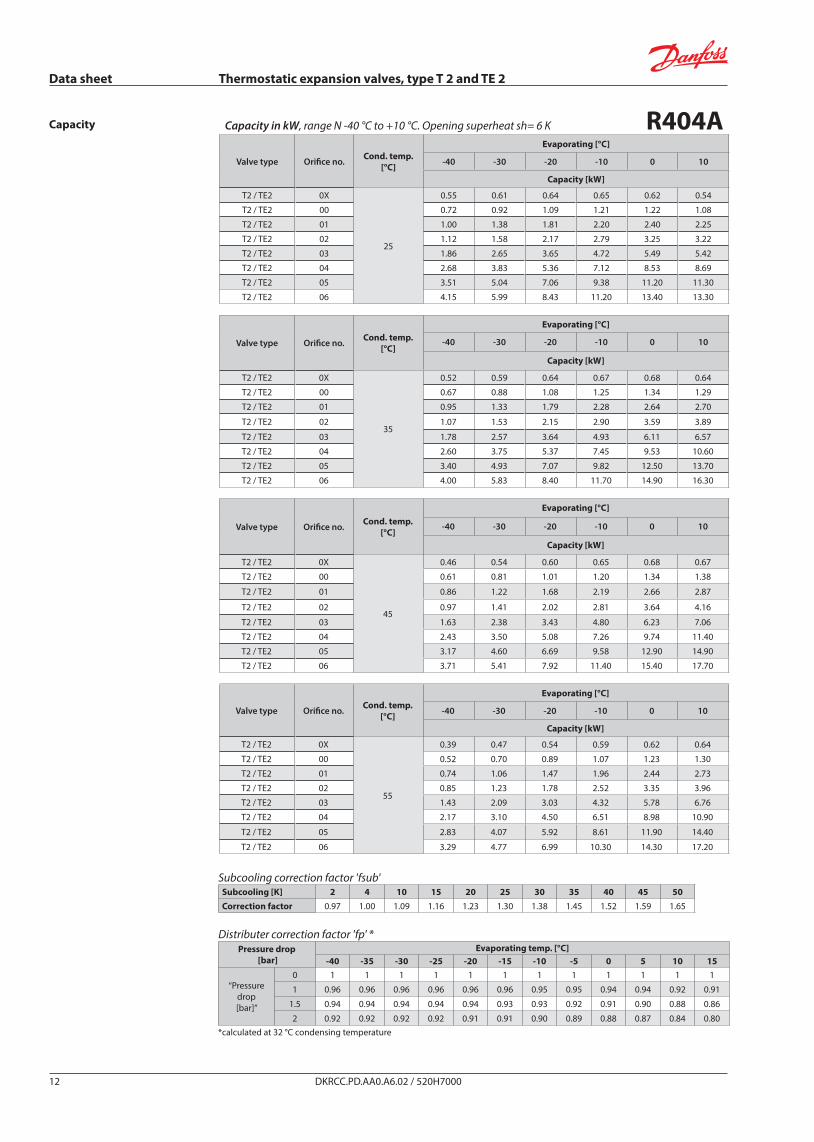
Capacity in kW, range N -40 °C to +10 °C. Opening superheat sh= 6 K R404AValve type Orifice no. Cond. temp.
[°C]
Evaporating [°C]
-40 -30 -20 -10 0 10
Capacity [kW]
T2 / TE2 0X
25
0.55 0.61 0.64 0.65 0.62 0.54
T2 / TE2 00 0.72 0.92 1.09 1.21 1.22 1.08
T2 / TE2 01 1.00 1.38 1.81 2.20 2.40 2.25
T2 / TE2 02 1.12 1.58 2.17 2.79 3.25 3.22
T2 / TE2 03 1.86 2.65 3.65 4.72 5.49 5.42
T2 / TE2 04 2.68 3.83 5.36 7.12 8.53 8.69
T2 / TE2 05 3.51 5.04 7.06 9.38 11.20 11.30
T2 / TE2 06 4.15 5.99 8.43 11.20 13.40 13.30
Valve type Orifice no. Cond. temp.[°C]
Evaporating [°C]
-40 -30 -20 -10 0 10
Capacity [kW]
T2 / TE2 0X
35
0.52 0.59 0.64 0.67 0.68 0.64
T2 / TE2 00 0.67 0.88 1.08 1.25 1.34 1.29
T2 / TE2 01 0.95 1.33 1.79 2.28 2.64 2.70
T2 / TE2 02 1.07 1.53 2.15 2.90 3.59 3.89
T2 / TE2 03 1.78 2.57 3.64 4.93 6.11 6.57
T2 / TE2 04 2.60 3.75 5.37 7.45 9.53 10.60
T2 / TE2 05 3.40 4.93 7.07 9.82 12.50 13.70
T2 / TE2 06 4.00 5.83 8.40 11.70 14.90 16.30
Valve type Orifice no. Cond. temp.[°C]
Evaporating [°C]
-40 -30 -20 -10 0 10
Capacity [kW]
T2 / TE2 0X
45
0.46 0.54 0.60 0.65 0.68 0.67
T2 / TE2 00 0.61 0.81 1.01 1.20 1.34 1.38
T2 / TE2 01 0.86 1.22 1.68 2.19 2.66 2.87
T2 / TE2 02 0.97 1.41 2.02 2.81 3.64 4.16
T2 / TE2 03 1.63 2.38 3.43 4.80 6.23 7.06
T2 / TE2 04 2.43 3.50 5.08 7.26 9.74 11.40
T2 / TE2 05 3.17 4.60 6.69 9.58 12.90 14.90
T2 / TE2 06 3.71 5.41 7.92 11.40 15.40 17.70
Valve type Orifice no. Cond. temp.[°C]
Evaporating [°C]
-40 -30 -20 -10 0 10
Capacity [kW]
T2 / TE2 0X
55
0.39 0.47 0.54 0.59 0.62 0.64
T2 / TE2 00 0.52 0.70 0.89 1.07 1.23 1.30
T2 / TE2 01 0.74 1.06 1.47 1.96 2.44 2.73
T2 / TE2 02 0.85 1.23 1.78 2.52 3.35 3.96
T2 / TE2 03 1.43 2.09 3.03 4.32 5.78 6.76
T2 / TE2 04 2.17 3.10 4.50 6.51 8.98 10.90
T2 / TE2 05 2.83 4.07 5.92 8.61 11.90 14.40
T2 / TE2 06 3.29 4.77 6.99 10.30 14.30 17.20
Capacity
DKRCC.PD.AA0.A6.02 / 520H700012
Subcooling correction factor 'fsub'Subcooling [K] 2 4 10 15 20 25 30 35 40 45 50Correction factor 0.97 1.00 1.09 1.16 1.23 1.30 1.38 1.45 1.52 1.59 1.65
Distributer correction factor 'fp' *Pressure drop
[bar]Evaporating temp. [°C]
-40 -35 -30 -25 -20 -15 -10 -5 0 5 10 15
“Pressure drop [bar]”
0 1 1 1 1 1 1 1 1 1 1 1 1
1 0.96 0.96 0.96 0.96 0.96 0.96 0.95 0.95 0.94 0.94 0.92 0.91
1.5 0.94 0.94 0.94 0.94 0.94 0.93 0.93 0.92 0.91 0.90 0.88 0.86
2 0.92 0.92 0.92 0.92 0.91 0.91 0.90 0.89 0.88 0.87 0.84 0.80*calculated at 32 °C condensing temperature

Data sheet Thermostatic expansion valves, type T 2 and TE 2
Capacity in kW, range B, -60 °C to -25 °C, opening superheat sh= 6 K R404AValve type Orifice no. Cond. temp.
[°C]
Evaporating [°C]
-60 -50 -40 -30
Capacity [kW]
T2 / TE2 0X
25
0.44 0.51 0.58 0.63
T2 / TE2 00 0.50 0.65 0.83 1.02
T2 / TE2 01 0.68 0.90 1.22 1.62
T2 / TE2 02 0.75 1.00 1.39 1.91
T2 / TE2 03 1.22 1.64 2.30 3.22
T2 / TE2 04 1.69 2.31 3.23 4.46
T2 / TE2 05 2.20 3.02 4.22 5.82
T2 / TE2 06 2.60 3.55 4.98 6.92
Valve type Orifice no. Cond. temp.[°C]
Evaporating [°C]
-60 -50 -40 -30
Capacity [kW]
T2 / TE2 0X
35
0.41 0.49 0.56 0.62
T2 / TE2 00 0.47 0.61 0.80 1.00
T2 / TE2 01 0.64 0.86 1.18 1.59
T2 / TE2 02 0.70 0.96 1.34 1.88
T2 / TE2 03 1.16 1.58 2.24 3.18
T2 / TE2 04 1.72 2.31 3.22 4.47
T2 / TE2 05 2.23 3.01 4.19 5.83
T2 / TE2 06 2.63 3.51 4.90 6.87
Valve type Orifice no. Cond. temp.[°C]
Evaporating [°C]
-60 -50 -40 -30
Capacity [kW]
T2 / TE2 0X
45
0.36 0.44 0.52 0.58
T2 / TE2 00 0.41 0.55 0.73 0.93
T2 / TE2 01 0.56 0.77 1.08 1.48
T2 / TE2 02 0.63 0.86 1.23 1.76
T2 / TE2 03 1.04 1.44 2.07 2.99
T2 / TE2 04 1.68 2.20 3.04 4.23
T2 / TE2 05 2.16 2.84 3.94 5.52
T2 / TE2 06 2.57 3.30 4.57 6.46
Valve type Orifice no. Cond. temp.[°C]
Evaporating [°C]
-60 -50 -40 -30
Capacity [kW]
T2 / TE2 0X
55
0.29 0.36 0.44 0.50
T2 / TE2 00 0.33 0.46 0.62 0.81
T2 / TE2 01 0.46 0.64 0.92 1.29
T2 / TE2 02 0.51 0.73 1.06 1.54
T2 / TE2 03 0.86 1.22 1.80 2.65
T2 / TE2 04 1.56 1.96 2.67 3.73
T2 / TE2 05 1.98 2.50 3.44 4.85
T2 / TE2 06 2.39 2.93 3.97 5.63
Capacity
DKRCC.PD.AA0.A6.02 / 520H700013
Subcooling correction factor 'fsub'Subcooling [K] 2 4 10 15 20 25 30 35 40 45 50Correction factor 0.97 1.00 1.10 1.19 1.27 1.35 1.43 1.52 1.60 1.68 1.76
Distributer correction factor 'fp' *Pressure drop
[bar]Evaporating temp. [°C]
-60 -55 -50 -45 -40 -35 -30 -25
“Pressure drop [bar]”
0 1 1 1 1 1 1 1 1
1 0.97 0.96 0.96 0.96 0.96 0.96 0.96 0.96
1.5 0.95 0.95 0.95 0.94 0.94 0.94 0.94 0.94
2 0.93 0.93 0.93 0.93 0.92 0.92 0.92 0.92*calculated at 32 °C condensing temperature
Data sheet Thermostatic expansion valves, type T 2 and TE 2
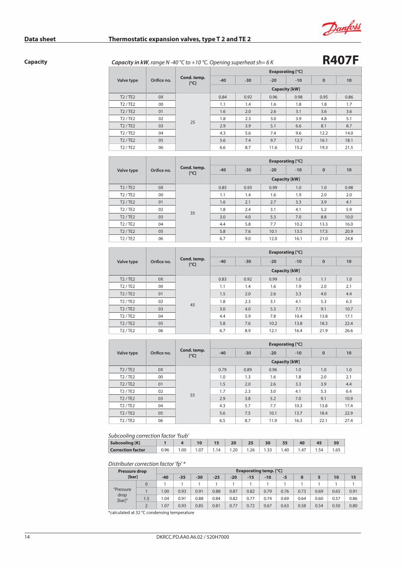
Capacity in kW, range N -40 °C to +10 °C. Opening superheat sh= 6 K R407FValve type Orifice no. Cond. temp.
[°C]
Evaporating [°C]
-40 -30 -20 -10 0 10
Capacity [kW]
T2 / TE2 0X
25
0.84 0.92 0.96 0.98 0.95 0.86
T2 / TE2 00 1.1 1.4 1.6 1.8 1.8 1.7
T2 / TE2 01 1.6 2.0 2.6 3.1 3.6 3.6
T2 / TE2 02 1.8 2.3 3.0 3.9 4.8 5.1
T2 / TE2 03 2.9 3.9 5.1 6.6 8.1 8.7
T2 / TE2 04 4.3 5.6 7.4 9.6 12.2 14.0
T2 / TE2 05 5.6 7.4 9.7 12.7 16.1 18.1
T2 / TE2 06 6.6 8.7 11.6 15.2 19.3 21.5
Valve type Orifice no. Cond. temp.[°C]
Evaporating [°C]
-40 -30 -20 -10 0 10
Capacity [kW]
T2 / TE2 0X
35
0.85 0.93 0.99 1.0 1.0 0.98
T2 / TE2 00 1.1 1.4 1.6 1.9 2.0 2.0
T2 / TE2 01 1.6 2.1 2.7 3.3 3.9 4.1
T2 / TE2 02 1.8 2.4 3.1 4.1 5.2 5.9
T2 / TE2 03 3.0 4.0 5.3 7.0 8.8 10.0
T2 / TE2 04 4.4 5.8 7.7 10.2 13.3 16.0
T2 / TE2 05 5.8 7.6 10.1 13.5 17.5 20.9
T2 / TE2 06 6.7 9.0 12.0 16.1 21.0 24.8
Valve type Orifice no. Cond. temp.[°C]
Evaporating [°C]
-40 -30 -20 -10 0 10
Capacity [kW]
T2 / TE2 0X
45
0.83 0.92 0.99 1.0 1.1 1.0
T2 / TE2 00 1.1 1.4 1.6 1.9 2.0 2.1
T2 / TE2 01 1.5 2.0 2.6 3.3 4.0 4.4
T2 / TE2 02 1.8 2.3 3.1 4.1 5.3 6.3
T2 / TE2 03 3.0 4.0 5.3 7.1 9.1 10.7
T2 / TE2 04 4.4 5.9 7.8 10.4 13.8 17.1
T2 / TE2 05 5.8 7.6 10.2 13.8 18.3 22.4
T2 / TE2 06 6.7 8.9 12.1 16.4 21.9 26.6
Valve type Orifice no. Cond. temp.[°C]
Evaporating [°C]
-40 -30 -20 -10 0 10
Capacity [kW]
T2 / TE2 0X
55
0.79 0.89 0.96 1.0 1.0 1.0
T2 / TE2 00 1.0 1.3 1.6 1.8 2.0 2.1
T2 / TE2 01 1.5 2.0 2.6 3.3 3.9 4.4
T2 / TE2 02 1.7 2.3 3.0 4.1 5.3 6.4
T2 / TE2 03 2.9 3.8 5.2 7.0 9.1 10.9
T2 / TE2 04 4.3 5.7 7.7 10.3 13.8 17.4
T2 / TE2 05 5.6 7.5 10.1 13.7 18.4 22.9
T2 / TE2 06 6.5 8.7 11.9 16.3 22.1 27.4
Capacity
DKRCC.PD.AA0.A6.02 / 520H700014
Subcooling correction factor 'fsub'Subcooling [K] 1 4 10 15 20 25 30 35 40 45 50Correction factor 0.96 1.00 1.07 1.14 1.20 1.26 1.33 1.40 1.47 1.54 1.65
Distributer correction factor 'fp' *Pressure drop
[bar]Evaporating temp. [°C]
-40 -35 -30 -25 -20 -15 -10 -5 0 5 10 15
“Pressure drop [bar]”
0 1 1 1 1 1 1 1 1 1 1 1 1
1 1.00 0.93 0.91 0.88 0.87 0.82 0.79 0.76 0.73 0.69 0.65 0.91
1.5 1.04 0.91 0.88 0.84 0.82 0.77 0.74 0.69 0.64 0.60 0.57 0.86
2 1.07 0.93 0.85 0.81 0.77 0.72 0.67 0.63 0.58 0.54 0.50 0.80*calculated at 32 °C condensing temperature

Data sheet Thermostatic expansion valves, type T 2 and TE 2
Capacity in kW, range N -40 °C to +10 °C. Opening superheat sh= 6 K R407AValve type Orifice no. Cond. temp.
[°C]
Evaporating [°C]
-40 -30 -20 -10 0 10
Capacity [kW]
T2 / TE2 0X
25
0.74 0.81 0.86 0.87 0.85 0.77
T2 / TE2 00 0.97 1.2 1.4 1.6 1.7 1.6
T2 / TE2 01 1.4 1.8 2.3 2.8 3.2 3.2
T2 / TE2 02 1.6 2.1 2.7 3.5 4.3 4.6
T2 / TE2 03 2.6 3.4 4.6 5.9 7.3 7.8
T2 / TE2 04 3.8 5.0 6.6 8.6 11.0 12.6
T2 / TE2 05 5.0 6.5 8.6 11.4 14.5 16.4
T2 / TE2 06 5.8 7.7 10.3 13.6 17.3 19.4
Valve type Orifice no. Cond. temp.[°C]
Evaporating [°C]
-40 -30 -20 -10 0 10
Capacity [kW]
T2 / TE2 0X
35
0.74 0.82 0.88 0.91 0.91 0.88
T2 / TE2 00 0.97 1.2 1.4 1.7 1.8 1.8
T2 / TE2 01 1.4 1.8 2.3 2.9 3.4 3.7
T2 / TE2 02 1.6 2.1 2.8 3.6 4.6 5.3
T2 / TE2 03 2.6 3.5 4.7 6.2 7.8 9.0
T2 / TE2 04 3.9 5.1 6.8 9.0 11.9 14.4
T2 / TE2 05 5.0 6.7 8.9 12.0 15.7 18.7
T2 / TE2 06 5.9 7.9 10.6 14.3 18.8 22.2
Valve type Orifice no. Cond. temp.[°C]
Evaporating [°C]
-40 -30 -20 -10 0 10
Capacity [kW]
T2 / TE2 0X
45
0.72 0.80 0.87 0.91 0.93 0.92
T2 / TE2 00 0.94 1.2 1.4 1.7 1.8 1.9
T2 / TE2 01 1.3 1.8 2.3 2.9 3.5 3.9
T2 / TE2 02 1.5 2.0 2.7 3.7 4.7 5.6
T2 / TE2 03 2.6 3.4 4.6 6.2 8.1 9.5
T2 / TE2 04 3.8 5.1 6.8 9.2 12.2 15.2
T2 / TE2 05 5.0 6.6 8.9 12.1 16.2 19.9
T2 / TE2 06 5.8 7.8 10.6 14.5 19.4 23.7
Valve type Orifice no. Cond. temp.[°C]
Evaporating [°C]
-40 -30 -20 -10 0 10
Capacity [kW]
T2 / TE2 0X
55
0.67 0.76 0.83 0.88 0.91 0.92
T2 / TE2 00 0.88 1.1 1.4 1.6 1.8 1.9
T2 / TE2 01 1.3 1.7 2.2 2.8 3.5 3.9
T2 / TE2 02 1.4 1.9 2.6 3.5 4.6 5.6
T2 / TE2 03 2.4 3.3 4.5 6.1 8.0 9.6
T2 / TE2 04 3.7 4.9 6.6 9.0 12.1 15.4
T2 / TE2 05 4.8 6.4 8.7 11.9 16.1 20.3
T2 / TE2 06 5.5 7.5 10.3 14.2 19.4 24.2
Capacity
DKRCC.PD.AA0.A6.02 / 520H700015
Subcooling correction factor 'fsub'Subcooling [K] 1 4 10 15 20 25 30 35 40 45 50Correction factor 0.96 1.00 1.08 1.14 1.21 1.28 1.35 1.42 1.50 1.57 1.65
Distributer correction factor 'fp' *Pressure drop
[bar]Evaporating temp. [°C]
-40 -35 -30 -25 -20 -15 -10 -5 0 5 10 15
“Pressure drop [bar]”
0 1 1 1 1 1 1 1 1 1 1 1 1
1 0.97 0.93 0.92 0.89 0.86 0.83 0.80 0.78 0.74 0.72 0.67 0.91
1.5 1.01 0.92 0.88 0.85 0.81 0.78 0.73 0.71 0.67 0.63 0.59 0.86
2 1.01 0.90 0.86 0.82 0.77 0.74 0.69 0.63 0.59 0.56 0.52 0.80*calculated at 32 °C condensing temperature

Data sheet Thermostatic expansion valves, type T 2 and TE 2
DKRCC.PD.AA0.A6.02 / 520H700016 DKRCC.PD.AA0.A6.02 / 520H7000 © Danfoss A/S (AG-SMC / sw), 01 - 2013
Dimensions and weights T 2 and TE 2
Flare × flareAll dimentions are in mm
All dimentions are in mmFlare × solder
Solder adaptor
OutletA
EqualizationB
Weight[kg / lb]
Flare × flare 1/2 ” flare 1/4 ” flare 0.3 / 0.7
Flare × solder1/2 ” solder
12 mm solder
1/4 ” solder 6 mm solder 0.3 / 0.7
Solder ODF Weight[kg / lb]in. mm
1/4 6 0.05 / 0.113/8 10 0.05 / 0.11