data buoy cooperation panel guide to data collection and
TRANSCRIPT

Intergovernmental Oceanographic World Commission of UNESCO Meteorological Organization
D A T A B U O Y C O O P E R A T I O N P A N E L
GUIDE TO DATA COLLECTION AND LOCATION SERVICES USING ARGOS
DBCP Technical Document No. 3
- 1 -

[this page left blank intentionally]
- 2 -
Intergovernmental Oceanographic World Commission of UNESCO Meteorological Organization
D A T A B U O Y C O - O P E R A T I O N P A N E L
GUIDE TO DATA COLLECTION AND LOCATION SERVICES USING ARGOS
DBCP Technical Document No. 3
REVISION 1
2011
- 3 -

CONTENTS
PREFACE......................................................................................................................................... 5
BACKGROUND TO THIS DOCUMENT........................................................................................ 5
1. INTRODUCTION ................................................................................................................... 6
1.1. OVERVIEW OF THE SYSTEM....................................................................................................... 6 1.2. ARGOS FOR METEOROLOGY AND OCEANOGRAPHY .................................................................... 7 1.3. GEOPHYSICAL VARIABLES....................................................................................................... 10 1.4. INTERNATIONAL COORDINATION THROUGH JCOMM – ARGO, DATA BUOY COOPERATION PANEL, SHIP OBSERVATIONS TEAM AND OCEANSITES ........................................................................ 12
2. DRIFTING BUOY HARDWARE ......................................................................................... 14
2.1. BUOY HULLS ........................................................................................................................... 14 2.2. SENSORS ................................................................................................................................. 14 2.3. DROGUES ................................................................................................................................ 16
3. THE ARGOS DATA COLLECTION AND LOCATION SYSTEM ..................................... 18
3.1. ARGOS PLATFORM TRANSMITTER TERMINALS (PTT) AND THE ARGOS-3 PLATFORM MESSAGING TRANSCEIVER (PMT) ........................................................................................................ 18 3.2. ARGOS SPACE SEGMENT .......................................................................................................... 21 3.3. ENHANCEMENTS WITH ARGOS-3 ............................................................................................. 24 3.4. TELEMETRY ACQUISITION ....................................................................................................... 25
4. ARGOS DATA PROCESSING ............................................................................................. 26
4.1. MESSAGE PROCESSING AND OBSERVATIONS............................................................................ 28 4.2. LOCATION PROCESSING ........................................................................................................... 30 4.3. ARGOS DATABASE................................................................................................................... 35
5. THE GTS PROCESSING SYSTEM...................................................................................... 36
5.1. SENSOR DATA PROCESSING ..................................................................................................... 36 5.2. QUALITY CONTROL................................................................................................................. 36 5.3. GTS DISTRIBUTION ................................................................................................................. 37 5.4. IDENTIFIER NUMBERS .............................................................................................................. 38
6. ON-LINE ACCESS TO ARGOS DATA................................................................................ 39
6.1. OVER THE GLOBAL TELECOMMUNICATION SYSTEM ............................................................... 39 6.2. OTHER ON-LINE AND OFF-LINE MODES .................................................................................... 39
7. QUALITY CONTROL .......................................................................................................... 40
8. BECOMING AN ARGOS SYSTEM USER........................................................................... 41
8.1. ESTABLISHING AN ARGOS PROGRAM....................................................................................... 41 8.2. FINANCIAL CONDITIONS .......................................................................................................... 42 8.3. MANAGING A PROGRAM .......................................................................................................... 43
9. GTS IRIDIUM PROCESSING AT CLS................................................................................ 44
ANNEX I: LIST OF PUBLICATIONS .......................................................................................... 45
ANNEX II: CONTACTS WITHIN THE DBCP............................................................................. 46
ANNEX III: CONTACTS FOR THE ARGOS SYSTEM ......................................................... 46
ANNEX IV: LIST OF ACRONYMS ........................................................................................ 49
- 4 -

PREFACE Thousands of ocean observing platforms worldwide are equipped with Argos transmitters, sending regular information via the Argos system to help scientists to understand the ocean environment, its impacts on the globe and predict climate change. More than 6,000 drifting buoys, profiling floats, moored buoys and fixed stations fitted with Argos transmitters measure ocean currents and send millions of measurements including atmospheric pressure, wind speed and direction, sea temperature and more, to monitor climate evolution. The utilization of these data buoys and many other remotely-located environmental observation systems depends critically on the data collection and location services provided by the Argos system. This system, which is flown on the NOAA (USA) Polar-orbiting Operational Environmental Satellites (POES) as well as the MetOp series of Satellites of EUMETSAT, is operated by CLS. It functions through the Argos Global Processing Centres in France and the USA, as well as through Local User Terminals (LUTs) in a number of countries.
BACKGROUND TO THIS DOCUMENT This report is an update to one which has been used extensively in the past and is a popular reference document for national Meteorological Services and all other users of the Argos system. The 1988 revised edition of the Guide to Data Collection and Location Services Using Service Argos was prepared by Dr. Glen Hamilton (USA), with substantial input being provided by the Technical Co-ordinator for the DBCP, Mr. David Meldrum and by the staff of CLS in Toulouse. The 1995 revised edition of the guide was prepared by the Technical Coordinator of the DBCP, Mr. Etienne Charpentier and by the staff of CLS in Toulouse with some input by Mr. Eric Meindl (USA).Their work is gratefully acknowledged and the thanks of WMO and IOC are extended to them for their time and efforts in support of this very valuable publication. The 1995 edition is basically to reflect recent improvements both in the Argos system and in the GTS data processing sub-system. This version has been updated in 2009, 2010, and 2011 using information from the CLS website and the Argos User’s Manual (http://www.cls.fr & http://www.argos-system.org/manual/) prepared by staff of CLS in Toulouse and compiled by the Technical Coordinator of the DBCP, Ms Hester Viola.
- 5 -

1. INTRODUCTION Argos is a global satellite-based location and data collection system dedicated to studying and protecting our planet's environment. It allows any mobile object equipped with a compatible transmitter to be located anywhere in the world. It also offers the possibility of collecting data from measurement sensors connected to this transmitter. The rules of the Argos system restrict its use to programs for studying and protecting the environment and protecting human life or programs of declared government interest. The Argos system results from Franco-American cooperation involving:
• CNES (French Space Agency),
• NOAA (National Oceanic and Atmospheric Administration), with support from NASA (National Aeronautics and Space Administration),
• CLS (Collecte Localisation Satellites), operator of the system. In 2006, EUMETSAT (European meteorological organization) joined the Operations Committee.
1.1. Overview of the System The Argos system comprises: - A set of user platforms, fixed or mobile, deployed at sea, on land or in the air and
transmitting independently and automatically to satellites in low polar orbit. The platform is the carrier complete with its sensors and Argos Transmitter (PTT or PMT).
- A full complement of sun-synchronous low polar orbit spacecraft (desirably 6 at any one
time maintained by NOAA and EUMETSAT), with instrument packages for Argos-2 and Argos-3+ that receive platform messages on a random access basis, then separate, time-code, format and retransmit the data to ground receiving stations. They can also send messages to the platform with two-way communications (PMT only)
- Ground stations which automatically transfer the messages to Argos Processing Centers.
The Processing Centers calculate the position of the transmitters and process the data measured by the sensors. Finally, the Processing Centers automatically deliver the results to the users. Any on e of these centres can take on the full operational workload if the other fails.
- Data access methods such as:
• secure connection to the ArgosWeb (www.argos-system.org) website,
• ArgosDirect automatic distribution (e-mail, ftp, fax or data transmission network, or CD-ROM),
• connection to ArgosWeb Service interface using a protocol based on SOAP (Simple Object Access Protocol) over HTTP.
• connection to ArgosServer transmission network (TELNET),
• ArgosShare allows users to share data with their colleagues and collaborators.
- 6 -

• ArgosMonitor monitors platform state, position and sensor data values, alerting users of any change in state by e-mail, SMS or fax.
• custom types of dispatch (archiving in a databank for up to twelve months, during which data can be sent on request).
1.2. Argos for meteorology and oceanography Argos has demonstrated its great potential for the collection of much needed observations from data sparse oceanic areas. Data collection platforms that utilize the Argos system for meteorological and oceanographic purposes can be categorized into three groups:
a) Moving surface platforms: drifting buoys, ships, ice buoys, marine animals; b) Fixed platforms: moored buoys and automatic weather stations; c) Sub-surface: profiling floats, marine mammals, ships based profiles, gliders.
The Argos system can automatically send data in real-time to the Global Telecommunication System (GTS) of the World Meteorological Organisation (WMO). The need for meteorological and oceanographic data from marine areas continues to increase. Many ocean observing platform operators conduct programmes with buoys, Argo floats, Ships and other platforms but not all of the data are disseminated onto the GTS. It is extremely important, and an ongoing challenge for the DBCP, to ensure that these data be made available to the worldwide community via the GTS. The Argos system has a fully integrated GTS processing chain (as of 2008) which allows data users to easily share their data on the GTS for any ocean platform, at no additional cost. Although drifting buoy technology was applied to oceanographic and meteorological problems prior to 1975, the launch of the NIMBUS satellite and, from 1978, the TIROS-N series satellites carrying the Argos system started an explosion of drifting buoy technology and applications in support of operational services and scientific experiments. The First GARP Global Experiment (FGGE) in the late 1970s was the first occasion to demonstrate the effectiveness of the Argos system for the global collection of meteorological data from drifting buoys. More than 300 drifters from Member countries were deployed in the southern hemisphere during the FGGE period. Sea-surface temperature and atmospheric pressure data from the buoys were collected by Argos and sent on to the GTS four times a day. The lifetime of the buoys proved to be longer than expected, some buoys transmitting valid data for over a year. Meteorological services then extensively deployed FGGE type meteorological buoys to measure atmospheric pressure, air temperature and sea surface temperature. Some of the buoys were equipped with reliable wind speed and wind direction sensors. Drifting buoys have a long history of use in oceanography, principally for the measurement of currents by following the motion of floating buoys attached to some form of sea anchor or drogue. Since 1988, thousands of Lagrangian drifters have been deployed in the world’s oceans as part of the the Surface Velocity Program (SVP) of the World Ocean Circulation Experiment (WOCE) and the Tropical Ocean and Global Atmosphere Program (TOGA) and since then as part of the Global Drifter Program (GDP). These buoys were standardized in 1991, with small spherical hull and floats and large Holey-Sock drogue centred at 15 meters below the surface. Over the years the buoy design has been improved and now they are very reliable, commercially produced and have half lifetimes greater than 450 days (with drogue still attached).
- 7 -

Buoys deployed primarily for oceanographic purposes may contribute useful meteorological data if equipped with suitable sensors and meteorological buoys may similarly provide oceanographic data. One community may be able to assist the other in the testing, deployment or tracking of buoys. This might take place on a local, national, regional or global scale. The DBCP is actively involved in such development and standardisation of hardware and bringing together the requirements of the two communities, among many other tasks. At its third session (Paris, October 1987) the DBCP adopted a recommendation urging greater co-operation between meteorologists and oceanographers in buoy instrumentation and deployments. Since then, cooperation between the two communities has increased steadily. Many regular operational meteorological buoys have been equipped with thermistor chains. In addition, the SVP Global Drifter Center (GDC) in the USA, operating from the Scripps Institution of Oceanography and NOAA, designed a low cost barometer drifter. In 1993 and 1994, under joint SVP/DBCP sponsorship and in cooperation between the GDC and meteorological services from Australia, Canada, France and the United Kingdom, more than 20 prototypes were deployed in the high sea and evaluated in an operational environment. The deployments demonstrated that the device could reliably meet both the meteorological and oceanographic communities’ requirements since it can accurately measure sea surface currents, sea surface temperature and atmospheric pressure. The Lagrangian Barometer Drifter, originally designed at the Scripps Institution of Oceanography for WOCE, is now commercially available at low cost and meets both oceanographic requirements (research: measurements of sea surface currents) and meteorological requirements (operational: air pressure). Until 1 November 1991, the WMO code format used for GTS distribution of drifting buoy data was FM 14-VII DRIBU. It was then replaced by FM 18-IX Ext. DRIFTER until 2 November 1994. Since then, the formal WMO code used for drifting buoys has been FM 18 BUOY (now FM 18-XII BUOY). The WMO is encouraging the migration of all data on the GTS to FM 94-XIV BUFR - Binary Universal Form for the Representation of Meteorological Data by 2012. Experimental transmission of Buoy data via the Argos system in BUFR started during 2003 and was validated for operational commencement by July 2003. All buoys which reported on the GTS in FM 18 BUOY format are now reporting in both formats, i.e. BUOY and BUFR. Buoy data will continue to be distributed in BUOY format until at least 2012 GTS bulletin headers used for BUFR reports have the following form: • "IOBXii LFVW" for the bulletins issued from the French Argos Global Processing Centre (FRGPC), Toulouse, France • "IOBXii KARS" for the bulletins issued from the US Argos Global Processing Centre (USGPC), Largo, USA Values for ii will remain the same as for the BUFR bulletin headers used for GTS distribution of the data in BUOY format. So for example data normally distributed in BUOY code under "SSVX02 KARS" will also be distributed in BUFR under "IOBX02 KARS". BUFR is basically a self defining binary code for exchanging meteorological data. A BUFR "message" is a contiguous binary stream composed of 6 sections. Section 0 contains the coded characters "BUFR" and Section 5 the coded characters "7777" indicating the beginning and the end of a BUFR message. Section 1, Identification Section, contains information about the contents of the data, such as type of data, time of data and whether or not the optional Section 2 is included in the message. Section 3 contains the description of the data that is represented in Section 4. Standard BUFR descriptors defined in BUFR tables B, C and D are used for that purpose. The buoy community has developed standard BUFR templates to report buoy data in BUFR.
- 8 -

Refer to the WMO Manual on Codes, Volume 1, International Codes, WMO No 306, Part B - Binary codes - for details. See : www.wmo.int Ice buoys have been used extensively in Arctic and Antarctic regions to track ice movement and are available commercially for deployment by ships or aircraft. Such buoys are equipped with low temperature electronics and lithium batteries that can operate at temperatures down to -50°C. In addition to the regularly-computed Argos locations the ice buoys can be equipped with satellite navigation receivers (e.g. Global Positioning System (GPS)) which can compute even more accurate positions for transmission through the Argos system. In 1991, an International Arctic Buoy Program (IABP) was established with the primary goal of maintaining an optimal array of ice buoys capable of measuring basic meteorological variables in the region for both operational and research purposes. In 1994, a World Climate Research Program (WCRP) International Program for Antarctic Buoys (IPAB) was created with similar goals in the Antarctic Sea Ice zone. The formal WMO code used for ice buoys is FM 18-XII BUOY and FM 94-XIV BUFR using templates agreed upon by the buoy community. Moored buoys are normally relatively large and expensive platforms. If a moored buoy comes loose from its tether, it represents a potential loss of costly equipment and a possible hazard to navigation. For these reasons the Argos system has been used for location determination for moored buoys (known as maintaining a watch circle). In addition, some Member countries use the Argos system for normal transmission of meteorological observations from moored buoys. The WMO code used for GTS distribution from the Argos system of moored buoy data is FM 18-XII BUOY and FM 94-XIV BUFR (as for drifting buoys). Automatic Weather Stations (AWS) are currently used in remote areas such as Greenland and Antarctica to collect meteorological data. In addition, some automatic land stations which normally report data via geostationary satellite are equipped with back up Argos reporting systems in the event that the primary system fails. The WMO code used for GTS distribution of AWS data from CLS/CLS America is FM 12-XIV SYNOP, this data will be sent in BUFR format by 2009. Sub-surface floats are autonomous free-drifting platforms gathering data at mid-depth and surfacing from time to time to transmit via Argos. Most sub-surface profiling floats are deployed in the high seas as part of the international Argo programme (www.argo.net), to collect temperature, salinity and current data. A broad-scale global network of profiling floats with 3° by 3° spacing has been implemented (beginning in late 1999) and will be maintained, as a major component of the ocean observing system. Argo reached its target of ~3000 floats delivering real-time data to researchers and operational centres worldwide, in 2007. The observations made from floats are always being extended for instance test are being undertaken for including acoustic wind and rain gauges, chemical or biological parameters. The mission parameters (such as time at depth, time on surface, drift and profile depth, vertical sampling) are pre-programmed for the entire mission and can vary to cater to regional needs. In general, floats drift at a depth of 1000m (to give a uniform velocity field) and profile to 2000m every 10 days so as to capture important variability. Argos system is used to transmit profiles (~100 levels) along with the locations.
- 9 -

Argo functions via national contributions, coordinated by an international Steering Team, and endorsed by the World Meteorological Organization and the Intergovernmental Oceanographic Commission of UNESCO. Argo data are freely available without restriction. A data system has been built by the Argo Data Management Team to efficiently distribute real time data, and delayed mode (with additional quality controls) from two Global Data Assembly Centres (FNMOC/USA and IFREMER/France), and onto the GTS of WMO. Standardized quality control procedures are used by all data providers. Data are distributed in controlled formats: - Sub-surface float data are disseminated onto the GTS principally in the FM 64 XI Ext TESAC format, this data will be sent via the Argos system in FM 94-XIV BUFR format by 2012. - NetCDF (4 files containing profile data, metadata, trajectory and technical description) for the Global Data Centres. Onboard Ships of Opportunity and Voluntary Observing Ships (VOS), since 1986, sub-surface temperature profiles measured by eXpendable BathyThermographs (XBTs) have been transmitted through dedicated Argos terminals then transferred onto the GTS using the code form FM 63-XI Ext. BATHY, this data will be sent in FM 94-XIV BUFR format by 2012.
1.3. Geophysical variables The variables measured by the data buoy network include one or more of the following elements: - Atmospheric pressure, - Atmospheric pressure tendency, - Wind speed, - Wind direction, - Air temperature, - Sea-surface temperature, - Sub-surface temperatures, - Sea surface salinity, - Sub-surface salinity, - Rainfall - Wave period and height - Relative Humidity.(Moorings only) - Down-welling Radiation (Moorings only) - Currents
Since the location of the drifting buoy is also determined in Argos processing, sea surface currents can be derived, provided that the buoy is a drogued lagrangian drifter.
measured with Doppler Current meter or Acoustic Doppler Current Profiler for moorings
Environmental observations required in support of meteorological and oceanographic services and research are discussed in relevant WMO and IOC publications (see Annex I). In these publications the relative priority of importance of measuring individual parameters is shown to depend to some extent on the type of user of the data. Clearly, however, atmospheric pressure and wind speed and direction are of utmost importance to weather forecasting and analysis and cannot be directly observed or measured by Satellite Remote Sensing. Sea-Surface Temperature (SST) is also of importance for weather analysis and forecasting and highly critical for fisheries, climate studies and other areas. SST data from drifting buoys are being used as ground truth
- 10 -

measurements for remote sensing applications. Air temperature is important for air/sea interaction and climate programmes. Observations of waves are important for all types of marine users. Current drift and sub-surface temperatures are very important for oceanographic applications. Interpreting buoy tracks used to be difficult. The lack of understanding regarding the effects of wind stress on drifting buoys and the currents of the uppermost few meters of water initially made many oceanographers cautious about directly relating buoy motions to ocean currents. Drogues substantially enhanced the ability of drifting buoys to represent ocean currents. Lagrangian drifters with high drag area ratios (e.g. >40) such as those developed for the WOCE/TOGA Surface Velocity Program (SVP) and used extensively today, measure sea surface currents with an accuracy of 2 cm/s. Using a correction formula, a wind correction will improve that accuracy to 1 cm/s if the wind is known to within 4 m/s. In addition, drogue lifetimes have been considerably increased. For example, Standard SVP Lagrangian Drifters equipped with Holey Sock drogues proved to have half lifetimes greater than 450 days with drogues still attached. Drogues on drifting buoys are also important for weather analysis and forecasting as they allow a longer residence time in remote ocean areas and reduce replacement costs. Measurements of surface (sea level) atmospheric pressure and SST have been routinely made by drifting buoys and are considered operationally proven. Winds are being measured on drifting buoys of some countries and are now considered reliable. Atmospheric pressure, SST and wind data from buoys are therefore routinely inserted in numerical weather prediction models. Air temperature measurements on drifting buoys can be useful for operational purposes, although the measurements are often made very close to the sea surface. Measurement of waves from drifting buoys is in the development stage and should be pursued. Measurement of sub-surface temperatures has proven feasible and has become operational, particularly in the tropics. Moored buoys measure all of these parameters reliably plus many others. The Global Tropical Moored Buoy Array is being implemented as an extension to the Tropical Atmosphere Ocean project, which has allowed the real time collection of many different meteorological and oceanographic (physical and biogeochemical) measurements to improve the detection and understanding of tropical cycles such as El Nino and La Nina in the Pacific. The Global Tropical Moored Buoy Array is a multi-national effort to provide data in real-time for climate research and forecasting. Major components include the TAO/TRITON array in the Pacific, PIRATA in the Atlantic and RAMA in the Indian Ocean. The major phenomena being studied using this array are:
• El Niño/Southern Oscillation (ENSO) in the Pacific
• The inter-hemispheric dipole mode, equatorial warm events and hurricane activity in the Atlantic
• The monsoons, the Indian Ocean Dipole and intra-seasonal variability in the Indian Ocean
- 11 -

1.4. International coordination through JCOMM – Argo, Data Buoy Cooperation Panel, Ship Observations Team and OceanSITES
Co-operation between the meteorological and oceanographic communities is an important factor for the promotion of ocean observing programmes. Meteorologists’ and oceanographers’ requirements are not mutually exclusive and they have much to gain by co-operation. Hardware developments aimed at one application may be beneficial to another. One community may be able to assist the other in the testing, deployment or tracking of buoys. This might take place on a local, national, regional or global scale. This sort of co-operation is a major goal of the Joint Technical Commission on Oceanography and Marine Meteorology (JCOMM) (http://www.jcomm.info). JCOMM is served by two technical coordinators within a centre, which is located in Toulouse France and is funded through voluntary contributions from Member States participating in the marine observing programme and panels such as DBCP and Argo. The centre is known as JCOMMOPS, the JCOMM in-situ observing platform support centre. (http://www.jcommops.org). Marine observations from in situ observing systems are paramount for generating good quality ocean products, such as ocean models. In situ observations can complement and provide a comparison point for other methods of observing the ocean. Observing systems need to meet the requirements set for ocean information products, therefore good international coordination is necessary to support all actors involved.
JCOMMOPS was established by the Joint WMO-IOC Technical Commission for Oceanography and Marine Meteorology (JCOMM) in 2001 based upon coordination facilities provided by the Data Buoy Cooperation Panel (including drifting and moored buoys), the Ship Observations Team (SOOP - XBT, TSG. ASAP - Atmospheric soundings from ships. VOS - Meteorological observations from ships ) and Argo profiling float programme. Synergy was therefore realised between these three global marine observational programmes, which can assist those in charge of implementing the National components of these programmes, through an integrated and international approach.
JCOMMOPS acts as a focal point for implementation and operation of relevant observing platforms. It provides support with programme planning, implementation and operations, including information on:
(i) observational data requirements, (ii) technology, instrumentation and costs, (iii) operational status of observing networks (e.g. identification of data sparse area) and (iv) deployment opportunities (by ship and air).
It maintains information on relevant data requirements for observations in support of GOOS, GCOS and the World Weather Watch of WMO as defined by the appropriate international scientific panels and JCOMM Expert Teams and Groups and routinely provides information on the functional status of the observing system. It also encourages platform operators to share data and distribute it in real-time and gives technical assistance with satellite data acquisition, automatic data processing and Global Telecommunication System (GTS) distribution of the data. JCOMMOPS also provides a mechanism for relaying quality information from data centres and users worldwide, back to national platform operators. It maintains information on relevant data requirements for observations in support of GOOS, GCOS and the World Weather Watch (WWW) of WMO as defined by the appropriate international scientific panels and JCOMM Expert Teams and Groups and routinely provides
- 12 -

information on the functional status of the observing system. It also encourages platform operators to share data and distribute it in real-time and gives technical assistance with satellite data acquisition, automatic data processing and Global Telecommunication System (GTS) distribution of the data. JCOMMOPS also provides a mechanism for relaying quality information from data centres and users worldwide, back to national platform operators. JCOMMOPS acts as a focal point for implementation and operation of relevant observing platforms. One of the technical coordinators works on the Argo Float programme and the Ship Observations Team and the other on the Data Buoy Cooperation Panel and OceanSITES. The Argos system serves many of the observing programs which come under JCOMM and CLS is actively involved in most of these and works closely with JCOMMOPS staff.
- 13 -

2. DRIFTING BUOY HARDWARE Drifting buoys have proven advantages as a sensor of choice for use in data-sparse ocean regions. Their small size makes deployment easy and inexpensive and allows for deployment from aircraft or ships. The basic hull, sensors and electronic configuration are simple and reliable and satisfactory performance has been obtained (following thorough design studies and testing) in rough and varied ocean conditions. The buoys are expendable, thereby avoiding the expense of recovery, maintenance, recalibration or refurbishing. A full description of drifting buoy hardware, as well as all other aspects of drifting buoys, is given in DBCP Technical Document 4 – SVP-B Design Manual.
2.1. Buoy hulls Buoy hull design depends mainly on the application. For real-time marine meteorological data acquisition it is important that the antenna be maintained above the water for optimum telemetry to the satellite. For this reason, most FGGE buoy hulls were of a simple spar and flotation collar configuration. Other design criteria include a low profile to minimize wind drag and low hull surface drag so the buoy can be used in a drogued configuration with minimal surface current effects. In the case of the SVP drifter the surface float is often submerged due to drag from the large current following drogue. Despite this undesirable feature, reliable communication is achieved and with the standardised SVP-barometer (SVP-B) drifter, surface atmospheric pressure measurements are possible. Buoy hulls are commonly constructed from a ABS plastic shell with a polyurethane filler to maintain buoyancy if the shell is penetrated. Power supplies have traditionally been provided by alkaline or lithium batteries. An important outcome of drifting buoy technology programmes has been the development of computer time-domain models to aid in the design of drifting buoy systems. With the model, the motions of a buoy hull can be simulated and the critical engineering parameters needed for design synthesis can be determined. The model can be used to predict the capability of a drifting buoy to measure the velocity of a parcel of water in which the buoy is embedded. The model can also be used to predict motions of buoys and forces within the buoy-tether-line-drogue system.
2.2. Sensors For buoys to contribute useful data to the Global Observing System (GOS) of the World Weather Watch (WWW) of WMO and to the World Climate Research Programme (WCRP), basic accuracy requirements relating to pressure, temperature and wind measurement should be met. Some of the requirements expressed in the WWW long-term plan for 1996 to 2005, are shown in Table 1, these have been revised since, but the basic aims remain the same for these variables.
- 14 -

Physical parameter Approximate range
Observational error (RMS)
Frequency of observations
Horizontal resolution
Surface atmospheric pressure
800 to 1050 hPa 0.2 to 1 hPa 1 to 24/day 250 km
Surface air temperature -50°C to 45°C 0.5°C 1 to 24/day 250 km
Surface wind vector 0 to 40 ms-1 1 to 2 ms-1 1 to 24/day 250 km
Sea surface temperature - 2°C to 35°C 0.5°C (ship) 0.2°C (buoy)
4/day 250 km
High Resolution SST (2008) - 2.0°C to 35.0°C 0.1°C (buoy) 4-24/day 5-10 km
Table 1 - Basic WWW Requirements.
The observational error (RMS) specified is linked to the total system accuracy of the buoy measurement system. The measurement accuracy should be maintained under the environmental operating conditions and lifetime of the system deployed. The individual contributor should allocate individual system component error sources to achieve the required system accuracy. Atmospheric Pressure: Measuring representative atmospheric pressure from a small drifting buoy in the open ocean is difficult. Error sources include: natural atmospheric pressure variation, wind interaction with the sensor, sensor error, data quantisation, sensor calibration and long-term drift, telemetry bit errors and the on-board selection of a measurement value characteristic of all values produced by the sensor during a particular time interval. Cost is also a significant consideration. Pressure sensors with inherently good long-term stability characteristics and good repeatability are expensive; however engineering advances have driven down the cost of barometers significantly. The limited power available on a small drifting buoy puts further constraints on the required operational characteristics of the sensor. Pressure measurement devices that have been employed in the past are aneroid cells, beam balance quartz crystal transducers and piezo-resistive transducers. Three air pressure sensors are now recommended although other sensors meeting the requirements (i.e. 1 hPa accuracy, less than 1hPa/year drift) could be chosen: Vaisala (e.g. PTB 101C) and Honeywell (PPT/HPB family) An important component of the measurement system, with regard to wind error, is the inlet or pressure port which allows the ambient pressure to be transmitted freely into the sensing element. The error or pressure change is related to the shape and configuration of the inlet and, for most configurations, the pressure error is related to the square of the wind velocity. Various schemes have been devised to correct this problem. Some pressure port designs have been tested in wind tunnels. During buoy developmental programmes problems have been encountered with water leakage through watertight seals and into barometer vents; water traps and drains and design changes were needed. This has been largely overcome in recent years. Air Pressure Tendency: This can be derived from latest and recorded Atmospheric Pressure measurements made at an interval of 3 hours. Computation is done onboard the buoy. Characteristics of the pressure tendency can also be computed and transmitted by the buoy.
- 15 -

Wind: Several countries have conducted development programmes in wind measurement from drifting buoys and various methods have been used. One approach is to measure the drag force on a sphere which is proportional to wind speed, another recent one is to acoustically detect the amount of turbulence or bubbles in the water which is proportional to the wind speed. The most conventional method would be to use cup or vane anemometers. The measurement of wind direction has concentrated on using a vane to point the buoy into the wind and use a compass to compute direction. The Argos system is capable of making an automatic geo-magnetic variation correction (using the current World Chart Model) on wind direction data to compensate for the bias due to the difference between true North and magnetic North. This correction depends on the buoy location and time of observation. Overall these tests have proven that it is difficult to measure wind from a small drifting buoy and the number of drifting buoys deployed with wind-measuring capability has dropped significantly since 2006. The number of Moored buoys measuring wind has increased in that time though, so overall more measurements of wind are being taken today than ever before. Air Temperature: Results of developmental tests have shown that air temperature can be measured satisfactorily using thermistors. A source of error is the heating effect produced when solar and infrared radiation strike the air temperature transducer. Various methods of constructing radiation shields have been devised. Sea Surface Temperature (SST): Measurements have routinely been provided by thermistors or resistance thermometers and reported temperature values have normally been within system specifications. Sub-surface Temperature: Measurements have been operationally collected from drifting buoys, usually to a depth of 150 m. Difficulties during deployment have brought to light the need for a self-contained deployment mechanism for these systems. Various cable designs have been tested and failure modes for sensors, wires and cables have been investigated. Sub-surface Temperature is routinely collected from many Moored Buoys, operationally using thermistor chains, to a depth of 750m. Sea Surface Salinity (SSS): Sensors are now being developed and tested on Lagrangian drifters. This is routinely collected on many Moored Buoys, sometimes to a depth of 750m. CO2 buoys: Several groups are currently testing the usefulness of drifting buoys for measuring carbon.
2.3. Drogues Confidence in the ability of drifting buoys to represent ocean currents is greatly enhanced by the addition of a sea anchor or drogue to increase the cross-sectional area of the buoy system at the depth at which the currents are to be measured. The most widely used form of drogue is now Holey-Sock drogues (a vertical cylinder made of fabric with open hoops at the end). TRISTAR (large semi-rigid, three axis symmetric drogue in the shape of a corner-radar reflector) designs are still being used. Older designs were parachute and window-blind drogues. Many other types of drogues are possible, e.g. various shapes made of rigid material and long lengths of rope weighted at the free end. Thermistor strings used to measure sub-surface temperature tend to act as drogues.
- 16 -
Buoy drift is due to the combination of wind drag and drag from the motion of the buoy, drogue and drogue line with respect to the water. In the simplest case, where the drogue is in the surface mixed layer, the current sensed by the buoy and by the drogue may be assumed to be the same. When the drogue is at a depth where the current is significantly different from that in the upper mixed layer the situation becomes much more complex. Differences in direction between the currents in the surface layer and those at the drogue depth may also lead to large errors in the apparent current at drogue depth. The most critical problem with drogues is separation from the buoy before the end of its operational life. In many cases it is not possible to unambiguously detect where in the buoy trajectory the drogue was lost. Several principles have been used in attempting to design a sensor which will indicate whether the drogue is still attached. The latest design records the portion of the time the buoy is submerged. In high seas, drifters with drogue detached are rarely submerged. New technologies have been developed and are being operationally tested to detect the presence of the drogue more easily. Strain gauge sensors have been recommended by the DBCP for the future, but this is still being tested by manufacturers for operational implementation. An important factor in drogue design for sea surface currents measurements is the drag area ratio. The drag area ratio is the drag coefficient of the drogue times the frontal area divided by the sum of the products of the drag coefficient and the largest projected frontal areas of floats and tethers. Normally drag area ratios larger than 40 are required for obtaining computed sea surface current accurate to 2 cm/s. For calibrated drifters a wind correction formula can improve that accuracy to 1 cm/s provided the wind field is known to within 4 m/s. (Source: Global Drifter Program)
- 17 -

3. THE ARGOS DATA COLLECTION AND LOCATION SYSTEM
3.1. Argos Platform Transmitter Terminals (PTT) and the Argos-3 Platform Messaging Transceiver (PMT)
Any platform used in conjunction with the Argos system, prior to 2008, carried an electronic transmitter termed a Platform Transmitter Terminal (PTT). A PTT includes an antenna, an RF modulator and power amplifier, message generation logic, a sensor interface unit, an ultra-stable oscillator and a power supply. Argos PTTs and PMTs must meet certain technical specifications and be approved by CLS. The first Argos-3 instrument, allowing two-way communication and 4.8 kbps high data rate channel, was launched on board the European Organization of the Exploitation of Meteorological Satellites (EUMETSAT) MetOp satellite in October 2006, the next NOAA N’ followed in early 2009, MetOp B was then planned for 2012. Currently satellites carrying Argos are planned for the next 20 years which guarantees a solid satellite link and coverage. As of 2009, operational tests of PMT commenced on ocean platforms using the Argos-3 system, which provides a greater volume of data in transmissions during each satellite pass, two-way communication functionality, platform remote control and re-programming and more efficient data transfer capabilities.
Table 2 - Evolution of Argos Instrument Capabilities
- 18 -

Argos-certified transmitters or transceivers are included within observational platforms. Each platform is characterized by an identification number specific to its transmission electronics. A platform transmits periodic messages characterized by the following parameters:
• transmission frequency (401.650 MHz ± 30 kHz), which must be stable as the location is computed on the basis of Doppler effect measurement in relation to this frequency,
• repetition period, which is the interval of time between two consecutive message dispatches, varying between 45 and 200 seconds according to the use of the platform, this is assigned by CLS exclusively based on the application of the transmitter
• platform identification number,
• all collected data. Transmitters are programmed to send messages to satellites at periodic intervals. Each message lasts 360 to 920 milliseconds. With Argos-3, transmitters can be programmed to transmit only when a satellite is in view. The transmitter message includes: a preliminary synchronization sequence, statement of message length, transmitter ID number, sensor data or user data (32 to 256 bits for Argos-2; 512 to 4608 bits for Argos-3) and a checksum. Radio frequency specifications
(a) Transmission frequency: All PTTs transmit on the same frequency band, from 401.650 ± .030 MHz. According to the ITU Radio Regulations this frequency falls in the 401-402 MHz band allocated to the Meteorological Aids Space Operation (space-to-earth). However it is understood that the PTT operator must obtain authority from his appropriate national authorities to transmit on this frequency.
(b) Transmission sequence: Each PTT transmits at regular intervals. The period currently ranges from 45 to 200 seconds for platforms depending on the type of application and the latitude of the PTT. For a given PTT the repetition period is fixed as allocated by CLS and must not be changed without authorization. The duration of a single transmission burst depends on the data message length but is always less than one second (360 to 920 milliseconds). This will vary for PMTs.
(c) Radiated power: The peak radiated power is less than 5 W which allows the use of low-power electrical sources like dry cells, batteries and even solar cells. Each PTT must also be equipped with a safety system which automatically switches off the PTT if it transmits continuously for more than one second.
(d) Modulation technique: The carrier is biphase-L-modulated by a 400 Hz PCM signal.
Oscillator stability The definition of PTT oscillator stability is frequency error divided by nominal carrier frequency (�f/f) and is characterised and evaluated as short-term, medium-term and long-term stability. Short-term stability: stability during the time to transmit a single message (normally between 360 and 920 milliseconds). The specification is in terms of a period of 100 milliseconds. If
- 19 -

short-term stability is worse than 10-8, the message will not be acquired by the Data Collection and Location System (DCLS), i.e. no data will be collected. For location-type PTTs, the stability must be better than 10-9; otherwise sensor data can be collected but location accuracy is poor. Medium-term stability: stability during a 10- to 15-minute satellite pass over a PTT, i.e. oscillator frequency drift. The results of simulated trials are summarized in Table 3 below. The table gives the theoretical effect on location accuracy due to oscillator frequency drift during the satellite pass. Medium-term stability Location accuracy Δf/f Hz/min meters 2x10⁻⁹ 0.04 <100
5x10⁻⁹ 0.10 200
10-8 0.20 400
2x10⁻⁸ 0.40 1,000
5x10⁻⁸ 1.00 2,000
10-7 2.00 4,000
2x10⁻⁷ 4.00 10,000
>2x10⁻⁷ calculation aborts
Table 3 - Location accuracy as a function of medium-term stability
Numerous tests show that the prime cause of poor medium-term stability is temperature variation during the satellite pass. The choice of oscillator thus depends on the location accuracy sought and on the platform environment. The temperature within, say, a buoy floating on the ocean surface is likely to be virtually constant. Thus, in such an application, a standard quality oscillator will almost certainly offer sufficient medium-term stability. Ultra-stable oscillators capable of accommodating steep temperature gradients are very expensive and often require large amounts of power for internal temperature regulation. In many cases, the required medium-term stability can be achieved using a standard oscillator inside a carefully insulated housing. Often this housing will take the form of a polystyrene or polyurethane box with a wall thickness of approximately 7 cm. Long term stability: stability during the period separating successive satellite passes, i.e. 100 minutes. If the previous transmission was received less than 12 hours before, a difference of more than 0.24 Hz/min is considered unacceptable. After 12 hours without reception, the long-term instability is automatically compensated by the location processing if it does not exceed 10- 6. However, if the long-term instability corresponds to a steady drift in the transmission frequency, then the operating limit will be determined by a ±4000 Hz tolerance. This has to be so since this tolerance was determined in accordance with the bandwidth specified for the onboard DCLS. The tolerance of ±4000 Hz can be broken down between the manufacturing tolerance and the ageing tolerance which depends on the PTT lifetime. Argos Data Collection and Location System (DCLS)
- 20 -
The onboard Argos DCLS receivers pick up the messages transmitted by platforms within the satellite coverage. Messages are separated in time through the asynchronization of transmissions and the use of different repetition periods. Messages are separated in frequency as a result of the different Doppler shifts in the carrier frequencies received from the various PTTs. Up to four simultaneous messages (eight after NOAA K) can be acquired by the Argos DCLS, provided they are separated in frequency. When a message is acquired the DCLS records the time of acquisition, measures the received carrier frequency and demodulates and records the PTT Identification (ID) code and the sensor data. These data are formatted and transmitted to the TIROS Information Processor (TIP). PTT certification To be compatible with the Argos onboard equipment and avoid interfering with other PTTs, each PTT design must be approved by CNES. For a newly-designed PTT the approval is based both on design analysis and on type certification tests. The type certification is requested by the PTT manufacturer and performed under CNES supervision in Toulouse (France). The manufacturer receives a type-certificate once his PTT has successfully passed the certification test. Once a PTT design has been type-certified, PTTs manufactured with the same design do not need further certification tests. All these production models must carry a label giving the type, the serial number and indicating that the type has been certified by CLS/CLS America. If any modification or design changes are made to the certified design it will be necessary to re-submit a prototype for testing and re-certification. A list of manufacturers supplying Argos-certified PTTs is available from CLS. For any new manufacturer intending to manufacture a newly-designed PTT, the detailed certification specifications must be requested from CLS. PMT Certification This work started in early 2005 with technical and marketing studies. The kernel of the product was clearly identified. It is made of a receiver, a transmitter, a relay to switch the unique antenna from reception to transmission and a controller to manage the satellite protocol and to support the communication with outside. A tender was issued and two manufacturers (Kenwood in Japan and ELTA in France) were selected in February 2006 to provide users with industrial PMTs at cost equal or lower than the current one-way PTTs. The first set of PMTs became available at the beginning of 2008.
3.2. Argos space segment The Argos system is evolving towards a two-way, interactive data collection system. This includes increasing the number of operational satellites (at least 6), increasing the data processing capability and efficiency, allowing downlink and uplink functionality and more flexibility.
The Argos instrument flies aboard POES (Polar Orbiting Environmental Satellites) satellites of the National Oceanic and Atmospheric Administration (NOAA) and MetOp, of the European Organization for the Exploitation of Meteorological Satellites (EUMETSAT). The first MetOp satellite was launched on 19 October 2006, the second flying on NOAA-N’ was launched in February 2009.
- 21 -

The next instruments will be carried on board the two MetOp satellites (planned for 2012 and 2016) and on SARAL (ISRO, India, planned for 2012). Cooperation projects with other space agencies are currently being studied.
Argos messages are received by the satellite then simultaneously: 1. stored on the onboard recorder and retransmitted to the ground each time the satellite passes
over one of the three main receiving stations: Wallops Island (Virginia, United States), Fairbanks (Alaska, United States), and Svalbard (Norway), or
2. retransmitted to the ground to regional reception stations in the satellites’ field of view.
The satellites are on a polar orbit at an altitude of 850 km: the satellites see the North and South Poles on each orbital revolution. The orbit planes revolve around the polar axis at the same speed as the Earth around the Sun, i.e. one revolution a year. Each orbital revolution transects the equatorial plane at fixed local solar times. Therefore, each satellite passes within visibility of any given transmitter at almost the same local time each day. The time taken to complete a revolution around the Earth is approximately 100 minutes.
At any given time, each satellite simultaneously "sees" all transmitters within an approximate 5000 kilometre diameter "footprint", or visibility circle. As the satellite proceeds in orbit, the visibility circle sweeps a 5000 kilometre swath around the Earth, covering both poles.
- 22 -

Due to the Earth's rotation, the swath shifts 25° west (2800 km at the Equator) around the polar axis at each revolution. This results in overlap between successive swaths. Since overlap increases with latitude, the number of daily passes over a transmitter also increases with latitude.
At the poles, the satellites see each transmitter on every pass, approximately 14 times per day per satellite. The Argos Web (http://www.argos-system.org/) allows prediction of satellite passes and transmission windows for any point on the globe and date/time plus predicts upcoming passes for any platform. Sensitivity to low-power signals The Argos instrument on-board existing NOAA satellites feature a receiver with sensitivity of -128 dB. Beginning with NOAA-K (1996), the instrument sensitivity will increase to -131 dB. This means that lower power signals can be received by the satellite, reducing transmitter power requirements. In theory, the power requirement will go down by approximately 50%, thus a 1 watt transmitter could be reduced to 500 milliwatts (all other conditions being equal). For some applications (such as Biology), where very low-powered transmitters are used, a special channel could be reserved from the expanded Argos bandwidth. To minimize interference from other transmitters, very low-power units would be programmed to broadcast on this part of the Argos band. In general, higher sensitivity will result in more messages being received at the satellite. It will also allow the spacecraft to receive messages for low-power transmitters more distant than is currently possible. The relationship between signal strength and PTT-to-spacecraft distance is a well known phenomenon. For very low-powered transmitters, messages sent at the beginning and end of each pass (low elevation passes) may be too low in power to be received. For these
- 23 -

PTTs, the stated 5,000 Km footprint is effectively reduced. Increasing sensitivity will allow more of these marginal messages to be received, effectively resulting in longer pass duration and better chances for successful location computation. The impacts of the higher sensitivity are broad in scope in that the general population of Argos transmitters will require less power. This transition should occur gradually as the existing inventory of transmitters is replaced. More immediate benefits will be gained by applications requiring very low power or transmitters in "marginal" situations. For these, the constraints presented by existing power requirements will be relaxed. Downlink Messaging Plans for future Argos instruments are to include a down-link messaging capability thereby establishing two-way communication. Down-link messaging will enable Users to send brief commands to their platforms. The commands could be used to simply turn transmitters on or off, or to perform more complicated tasks. For example, sensors could be controlled, measurement modes could be changed and transmitters could be programmed, ID numbers could be changed. Messages could be broadcast, for example housekeeping data such as orbit predictions sent to all platforms, messages sent to particular groups of platforms (group calls) The downlink signal can be used by the platforms to detect the arrival of the satellite. All messages to be forwarded to platforms would be sent through one of the Global Processing Centers. Messages would be uploaded to the next available satellite and retransmitted either immediately or at a designated time, depending on the message type. Users would submit their requests for a down-linked message much like current requests for changes to processing options.
3.3. Enhancements with Argos-3 With Argos-3 the following features have become available: - Two-way communication via a downlink with a new generation of Argos platforms — the
Platform Messaging Transceivers (PMTs). All downlink communication is managed by the Downlink Messaging Management Center (DMMC), operated by CLS for the French Space Agency, CNES, in Toulouse, France.
- A high speed 4.8 kbit/s uplink, allowing ten times more data to be transferred per satellite pass than before. Combined with the downlink capability, the high data rate link increases the amount of data collected.
- No redundancy in the messages sent like with the one-way Argos system (Argos-1, Argos-2) which required redundant messages to increase the probability of data being received by satellites error-free. With Argos-3, redundant messages are no longer necessary, since the downlink allows the Argos-3 instrument to send an “Acknowledgement” signal to the PMT once data has been received error-free. Once the PMT receives the “Acknowledgement,” it stops sending the message.
- Ability to equip all PMTs with satellite pass forecasting software and to calculate the exact time and duration of the next satellite pass, thanks to information communicated by system operators via the downlink. The result is that PMTs only transmit when a satellite is in view, reducing transmission time, conserving energy and extending platform lifetime.
- Users have the opportunity to send short messages to their platforms (up to 128 bits by 8 bit increments) via the Downlink Message Management Center (DMMC). Typical applications include switching a transmitter on or off, changing time or date configurations, modifying a
- 24 -
sensor sampling rate or any other possible remote command allowed by the platform. The DMMC will relay the command, allowing users to program their platforms remotely.
- The Argos-3 instrument — as well as all future two-way instruments — is completely compatible with existing platforms. It offers increased flexibility with improving data collection and location capability by "tuning" platform transmission and duty cycles.
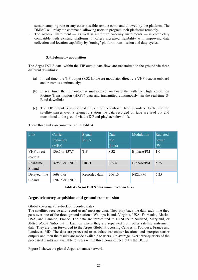
3.4. Telemetry acquisition The Argos DCLS data, within the TIP output data flow, are transmitted to the ground via three different downlinks:
(a) In real time, the TIP output (8.32 kbits/sec) modulates directly a VHF-beacon onboard and transmits continuously;
(b) In real time, the TIP output is multiplexed, on board the with the High Resolution
Picture Transmission (HRPT) data and transmitted continuously via the real-time S-Band downlink;
(c) The TIP output is also stored on one of the onboard tape recorders. Each time the
satellite passes over a telemetry station the data recorded on tape are read out and transmitted to the ground via the S-Band-playback downlink.
These three links are summarized in Table 4. Link Carrier
frequency (MHz)
Signal source
Data rate (kbps)
Modulation Radiated power (W)
VHF direct readout
136.7 or 137.7 TIP 8.32 Biphase/PM 1.0
Real-time, S-band
1698.0 or 1707.0 HRPT 665.4 Biphase/PM 5.25
Delayed time S-band
1698.0 or 1702.5 or 1707.0
Recorded data 2661.6 NRZ/PM 5.25
Table 4 - Argos DCLS data communication links
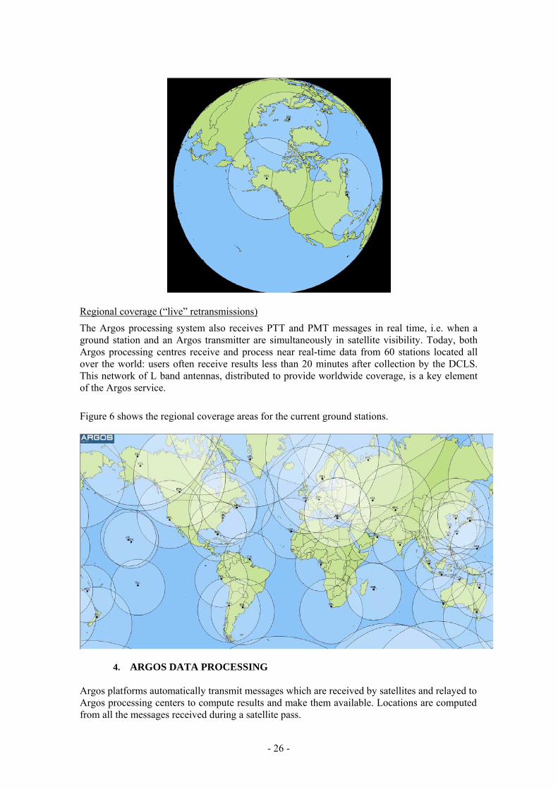
Argos telemetry acquisition and ground transmission Global coverage (playback of recorded data) The satellites receive and record users’ message data. They play back the data each time they pass over one of the three ground stations: Wallops Island, Virginia, USA; Fairbanks, Alaska, USA; and Lannion, France. The data are transmitted to NESDIS in Suitland, Maryland, or Météorologie Nationale in Lannion where they are separated from other satellite instrument data. They are then forwarded to the Argos Global Processing Centres in Toulouse, France and Landover, MD. The data are processed to calculate transmitter locations and interpret sensor outputs and then the results are made available to users. On average, over three-quarters of the processed results are available to users within three hours of receipt by the DCLS. Figure 5 shows the global Argos antennas network.
- 25 -
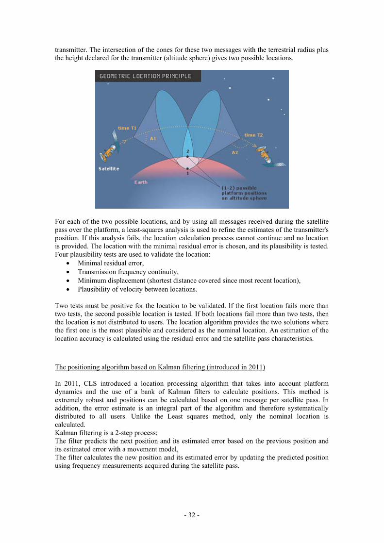
Regional coverage (“live” retransmissions) The Argos processing system also receives PTT and PMT messages in real time, i.e. when a ground station and an Argos transmitter are simultaneously in satellite visibility. Today, both Argos processing centres receive and process near real-time data from 60 stations located all over the world: users often receive results less than 20 minutes after collection by the DCLS. This network of L band antennas, distributed to provide worldwide coverage, is a key element of the Argos service. Figure 6 shows the regional coverage areas for the current ground stations.
4. ARGOS DATA PROCESSING Argos platforms automatically transmit messages which are received by satellites and relayed to Argos processing centers to compute results and make them available. Locations are computed from all the messages received during a satellite pass.
- 26 -

Two processing centers with redundant operation, one near Washington D.C. (United States) and the other in Toulouse, France, process all received data. The computers calculate locations and process the received data.
The following processing is carried out at the global processing centers:
• check of message quality, reception level, time-tagging, transmitter identification number, sensor message lengths and received frequency value (to compute the location);
• message time-tagging in coordinated universal time (UTC);
• message classification by platform and by chronological order;
• data processing. All these results are stored and made available to users. The following processing tasks are then performed:
(a) Decoding of the PTT messages and processing of the sensor data; (b) Computation of PTT locations from Doppler shifts and orbital data; (c) Storage of all these processing outputs in a database which is accessible on-line.
Data processing at the Argos Global Processing Centres does not presently include procedures for averaging data received from buoys. Sensor data processing on the buoys is therefore required. The physical parameters measured by the buoy system need to be averaged to minimize errors resulting from buoy motion and environmental variability. The desirable goal is at least a one-minute average on the atmospheric pressure and surface water temperature measurement. If digital averaging techniques are used, a minimum of ten data samples should be used to obtain the average during the measurement period. It is important to note that, sensor values are controlled, in addition to WMO quality controls procedures, by a checksum control test if present in the data format message or a two identical sensor values test (not necessarily consecutive; in addition, whole Argos messages don't have to be identical) from a PTT during a satellite overpass before those observations will be put on the GTS.
- 27 -

4.1. Message processing and observations
The above schema illustrates the different steps involved in collecting and processing in-situ data at CLS:
1. Data acquisition: The platform collects data and dates the observations.
2. Message building: The measurements are dated, encoded and recorded in messages.
3. Messages sent to satellites: Messages are then sent by the Argos transmitter (PTT) or modem (PMT) to the satellites.
4. Data received by satellites: The satellites receive the messages, date them and measure signal frequency.
5. Messages transmitted back to the ground: The satellites then retransmit to ground stations all received messages, along with the date they were received and frequency measurements.
6. Message processing: Argos centers calculate platform positions by processing the received frequency measurements (Doppler Effect), or by extracting the GPS positions contained in the messages. Messages are then decoded in accordance with user’s needs.
7. Observation processing: The observations made by the platform are extracted from messages, dated, given a geolocation and validated.
Since May 20, 2008, complete Observation processing (Step 7) has been available for all Argos platforms. User results are currently available in two formats:
• Message format: User results are grouped together by satellite pass, then distributed along with a location (corresponds to the location calculated for the satellite pass).
- 28 -

• Observation format: Physical data (sensor measurements) are dated and assigned a location based on the time the observation was made and the best corresponding location (calculated as close to the observation time as possible).
Multi-format data processing The Argos processing system can handle several message formats for one transmitter. A message format is a specific type of message sent by an Argos platform. Each format has a specific structure. The Argos processing system can now handle processing of a variety of formats for the same platform. Here is an example of how the processing system works for an Argos platform transmitting three different types of messages:
Three different types of messages from one platform are converted into physical values by the
Argos processing system. Standard sensor data processing There are several types of standard sensor data processing. For each individual sensor data set being processed, the user or the platform manufacturer has to define the processing option and parameters: Data decoding converts a raw binary value into a physical value. Main transfer functions are available and specific processing module (software module), subject to acceptance by Argos processing experts, could be developed by CLS.
Observation Processing The new capabilities of the Argos processing system make it possible for users to receive the decoded physical values measured by a platform’s different sensors. These resulting observations are time-stamped (marked with the date and time calculated or transmitted by the platform), then the dated observations are assigned a location, based on the closest corresponding Argos or GPS position.
- 29 -

Observation processing is performed independently of Message processing and therefore does not affect user’s results processed and distributed in Message format. As shown in the schema below, the observation calculation process does not interfere with the Message processing procedure. User results are still available in Message format via the usual Argos data distribution channels (ArgosDirect, ArgosServer, ArgosWeb…).
Another significant advantage of observations is a reduction in the amount of data distributed. This reduction is due to the quality-controls performed (checksum, compression index for sensor values,…) as well as to the suppression of redundant messages. To take advantage of Observation processing, users must provide the related data decoding and assembly parameters to their User Services Group, with a description for each different platform type (this information is generally available from the platform manufacturer). Observation processing is already available for meteorological platforms that distribute their data to the GTS.( see section 5.3 or the Argos Users Manual)
4.2. Location processing Argos platforms automatically transmit messages which are received by satellites and relayed to Argos processing centers to compute results and make them available. Locations are computed from all the messages received during a satellite pass. Argos system users have the advantage of two independent positioning modes:
• Argos location: Argos centers calculate a transmitter's location using the Doppler Effect on transmission frequency. Since 2011, Argos users must choose between two location processing algorithms:
Least squares analysis: Historically, Argos locations are calculated using a least-squares analysis
Kalman filtering: In 2011, this algorithm was introduced to provide more positions and better accuracy.
• GPS positioning: On request from the user, a specific processing module extracts the GPS positions included in the messages, validates them and distributes them in the same format as the Argos locations.
- 30 -

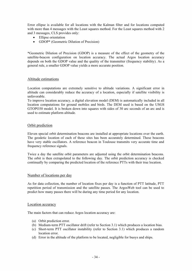
In both cases, the coordinates used are the latitude and longitude and the reference system is WGS 84 (World Geodetic System 1984). The Argos system calculates locations by measuring the Doppler Effect on transmission frequency. The Doppler Effect is the change in frequency of a sound wave or electromagnetic wave that occurs when the source of vibration and observer are moving relative to each other. The Doppler Effect The classic case is when an observer notices a change in the sound when a train approaches and moves away. Similarly, when the satellite approaches a transmitter, the frequency of the transmitted signal measured by the onboard receiver is higher than the actual transmitted frequency and lower when it moves away.
Each time the satellite instrument receives a message from a transmitter, it measures the frequency and time-tags the arrival. A major feature of the Doppler location is the existence of two possible positions of the platform that give exactly the same frequency measurements on board the satellite: the nominal ("true") location and the mirror ("virtual") location. They are symmetrical about the sub-satellite track and, unfortunately, they are not a priori distinguishable. Since 2011, users can choose between two location processing algorithms for Argos. Both techniques compute the Doppler frequency shift on the transmitters signal. The positioning algorithm based on Least squares analysis (unchanged since 2007) If four or more messages are received by the satellite, the location calculation process follows the following steps. An initial estimate of the platform position is computed from the first and last messages collected during a single satellite pass and the last computed frequency of the
- 31 -
transmitter. The intersection of the cones for these two messages with the terrestrial radius plus the height declared for the transmitter (altitude sphere) gives two possible locations.
For each of the two possible locations, and by using all messages received during the satellite pass over the platform, a least-squares analysis is used to refine the estimates of the transmitter's position. If this analysis fails, the location calculation process cannot continue and no location is provided. The location with the minimal residual error is chosen, and its plausibility is tested. Four plausibility tests are used to validate the location:
• Minimal residual error, • Transmission frequency continuity, • Minimum displacement (shortest distance covered since most recent location), • Plausibility of velocity between locations.
Two tests must be positive for the location to be validated. If the first location fails more than two tests, the second possible location is tested. If both locations fail more than two tests, then the location is not distributed to users. The location algorithm provides the two solutions where the first one is the most plausible and considered as the nominal location. An estimation of the location accuracy is calculated using the residual error and the satellite pass characteristics.
The positioning algorithm based on Kalman filtering (introduced in 2011) In 2011, CLS introduced a location processing algorithm that takes into account platform dynamics and the use of a bank of Kalman filters to calculate positions. This method is extremely robust and positions can be calculated based on one message per satellite pass. In addition, the error estimate is an integral part of the algorithm and therefore systematically distributed to all users. Unlike the Least squares method, only the nominal location is calculated. Kalman filtering is a 2-step process: The filter predicts the next position and its estimated error based on the previous position and its estimated error with a movement model, The filter calculates the new position and its estimated error by updating the predicted position using frequency measurements acquired during the satellite pass.
- 32 -

Three plausibility tests are used to validate the location:
• Coherency of measurements with the model used (in mathematical terms, we analyze the likelihood of the Kalman filter’s innovation
• Transmission frequency continuity, • Plausibility of velocity between locations.
All tests must be positive for the location to be validated. For all locations, an estimation of the accuracy is provided.
Error estimation Due to the satellite’s polar orbit, the Argos position error is better represented by an ellipse rather than by a circle. For those users who wish to use it, CLS provides the following values corresponding to the ellipse of error for all locations:
• Error radius • Length of the semi-major axis • Length of the semi-minor axis • Ellipse orientation (expressed as an angle with the North, going towards to the East) • GDOP* (Geometric Dilution of Precision)
- 33 -
Error ellipse is available for all locations with the Kalman filter and for locations computed with more than 4 messages with the Least squares method. For the Least squares method with 2 and 3 messages, CLS provides only:
• Ellipse orientation • GDOP* (Geometric Dilution of Precision)
*Geometric Dilution of Precision (GDOP) is a measure of the effect of the geometry of the satellite-beacon configuration on location accuracy. The actual Argos location accuracy depends on both the GDOP value and the quality of the transmitter (frequency stability). As a general rule, a smaller GDOP value yields a more accurate position.
Altitude estimations Location computations are extremely sensitive to altitude variations. A significant error in altitude can considerably reduce the accuracy of a location, especially if satellite visibility is unfavorable. To improve location accuracy, a digital elevation model (DEM) is automatically included in all location computations for ground mobiles and birds. The DEM used is based on the USGS GTOPO30 model. It is broken down into squares with sides of 30 arc seconds of an arc and is used to estimate platform altitude. Orbit prediction Eleven special orbit determination beacons are installed at appropriate locations over the earth. The geodetic location of each of these sites has been accurately determined. These beacons have very stable oscillators. A reference beacon in Toulouse transmits very accurate time and frequency reference signals. Twice a day the satellite orbit parameters are adjusted using the orbit determination beacons. The orbit is then extrapolated to the following day. The orbit prediction accuracy is checked continually by comparing the predicted location of the reference PTTs with their true location. Number of locations per day As for data collection, the number of location fixes per day is a function of PTT latitude, PTT repetition period of transmission and the satellite passes. The ArgosWeb tool can be used to predict how many passes there will be during any time period for any location. Location accuracy The main factors that can reduce Argos location accuracy are:
(a) Orbit prediction error. (b) Medium-term PTT oscillator drift (refer to Section 3.1) which produces a location bias. (c) Short-term PTT oscillator instability (refer to Section 3.1) which produces a random
location error. (d) Error in the altitude of the platform to be located, negligible for buoys and ships.
- 34 -

Location accuracy classes From the beginning of Argos service, locations have been classified according to the following criteria:
• type of location (Argos or GPS), • estimated error, • number of messages received during the pass.
Regardless of the number of messages received during a satellite pass, an estimated error is calculated. For classification purposes, the error is assumed to be isotropic and hence characterized by a single number called the radius of error. It corresponds to one standard deviation (sigma) of the estimated location error. The location class is attributed based on the radius of error. The location class and associated error is sufficient for many applications. Still, the location error is not strictly isotropic and hence is better approximated by an ellipse than by a circle.
Estimated error* Number of messages received per satellite pass
Class Type
Least Squares Kalman Filter Least Squares Kalman Filter
G GPS < 100m 1 message or more
3 Argos < 250m 4 messages or more
2 Argos 250m < < 500m 4 messages or more
1 Argos 500m < < 1500m 4 messages or more
0* Argos > 1500m 4 messages or more
A* Argos No accuracy estimation
Unbounded accuracy estimation
3 messages
B* Argos No accuracy estimation
Unbounded accuracy estimation
messages 1 or 2 messages
Table 6 - Argos Location Classes
* Class 0,A and B locations are available by request only.
4.3. Argos database The Argos Processing Centers performs sensor data processing and location processing in parallel. The output of these two operations is stored in a master data bank which contains all the data acquired over the last 2 years. The data are sorted by programme, PTT and date and are stored in a relational database (with redundancy between teh USA and France). The data are also available on line as raw data or observations.
- 35 -

5. THE GTS PROCESSING SYSTEM
A dedicated GTS processing chain operates at both French and the US Global Processing Centre (Toulouse and Largo, MD). Platform sensor data are decoded, processed in geophysical units, quality controlled, encoded in WMO code formats and disseminated onto the GTS in real time. These data are visible to operators using the Argos website http://www.argos-system.org . The Argos GTS processing used to be a separate sub-system but since 2008 it has been integrated fully into the Argos System, meaning that the raw data and the observations sent onto the GTS appear in the Argos system seamlessly. This is a very flexible system, hence data delivered to the owners of the stations and data disseminated on GTS can be processed in different ways. For example, owners can receive the raw data on line from an Argos centre and at the same time have geophysical units sent through for GTS distribution. The Global Telecommunication System (GTS), is a network run by the World Meteorological Organization (WMO), to facilitate data exchange between national weather centers. Data from a number of Argos programs are important for the GTS, namely because they can be fed into national weather centers' real-time weather forecasting models. Argos users can contribute by authorizing the distribution of their meteorological and oceanographic data to the GTS processing system, free of charge. Data are automatically quality-controlled and put into WMO formats in order to be posted on GTS. Nevertheless, posting data onto the GTS does not impact the structure or content of the initial Argos data. Therefore, users may request other formats than GTS formats for the data they receive. For example, the Argos processing center can apply different types of processing and calibration curves according to whether the data is to go onto the GTS or to the Principal Investigator (PI). The PI can receive the raw data. Similarly, file updates on GTS requirements/specifications (e.g. removing a transmitter, or removing or recalibrating a sensor) have no impact on a user's Argos requirements/specifications.
5.1. Sensor data processing The GTS processing system allow flexibly in processing sensor data. For example, sensor binary outputs can be placed in any order in the Argos message transmitted by the platforms. Sensor binary output is limited to 32 bits.
5.2. Quality Control Thanks to several automatic Quality Control (QC) checks, erroneous data are detected and not distributed on the GTS distribution. These QC tests, which can be turned off on request, are:
(a) Gross Error check. Sensor data are compared with constant limits.
(b) User Limits check. The limits are provided by the owner of the platform for each sensor on each platform;
(c) Sensor blockage test. Same sensor value reported consecutively a certain number of
times during a certain period (this test is normally used only for Air Pressure sensors); (d) All bits identical test. All the bits of the sensor binary output are ones or zeros (this test
is usually not used for Wind Speed, Wind Direction or Pressure Tendency);
- 36 -

(e) Compression Index by sensor. At least two identical sensor values for a satellite pass
must be received (values don't have to be consecutive); (f) Checksums. If the option is used, the sum encoded in the Argos message must still be
consistent upon reception at the Argos centre. If not consistent, the data are not distributed on the GTS.
In addition, the following procedures are applied:
(a) If GTS dissemination of the station location is required, only the location with the highest probability of being correct is transmitted;
(b) If GTS dissemination of the station location is required, when location processing is not performed during a satellite pass, the last known location is provided;
(c) For drifting buoys, data with location more than 48 hours old are not transmitted via the GTS (24 hours for ships, longer periods or no limit for other types of platforms).
DBCP Technical Document No. 2 provides more detail on these quality control procedures.
5.3. GTS distribution Sensor data measured at the same time for the same platform are grouped and encoded into single GTS reports (i.e. Observations or groups of observations). GTS reports encoded using the same WMO code are grouped into what are known as bulletins. Bulletins are transmitted directly from CLS to Météo-France, Toulouse and to the National Weather Service, Washington, D.C. for dissemination over the GTS. The following GTS code formats can be used for GTS distribution:
FM 18-XII BUOY Report of a buoy observation, FM 12-XIV SYNOP Report of surface observation from a land station, FM 13-XIV SHIP Report of surface observation from a sea station, FM 63-XI Ext. BATHY Report of a bathythermal observation, FM 64-XI TESAC Temperature, salinity and current report from a sea station, FM 94-XIV BUFR CLS has a fully functional BUFR encoding and decoding
utility to support this future data format for the GTS and the WIS (see Annex II for details) - using appropriate templates as developed by the user community
These codes are described in publication WMO-No. 306, Volume I and reproduced partially in Annex III. How to set up GTS distribution service Users can request that their data be distributed on the GTS by contacting User Services and filling out a GTS technical file. The user must also contact the DBCP in order to obtain a WMO number, essential for transmitting data via GTS. Deployers of drifting buoys are encouraged to make the data obtained from their buoys available to the global user community, both operational and research, by disseminating data over the GTS. Basic rules for contributing data to the GTS:
(a) The programme must have had prior Argos formal agreement and the sensor data must have meteorological or oceanographic value as defined below;
- 37 -

(b) The data must be capable of being transmitted in one of the valid WMO codes or BUFR formats,
(c) Programme owners must have contacted their National Weather Service and/or National Focal Point for drifting buoy programmes (see Annex II) so that national procedures for inserting data onto the GTS are followed. In particular, WMO identifiers have to be assigned to each platform in accordance with WMO rules (see http://www.jcommops.org/wmo_numbers.html);
(d) The platform owner/operator must pass these WMO identifiers to CLS, when the platforms have become operational, so that GTS transmission may commence;
(e) Necessary information for decoding the Argos messages and converting the sensor data into physical units must be provided to CLS (i.e. Argos message format, calibration curves). A GTS Technical file is available from the Argos User Offices.
(f) After deployment, deployers must carry out quality control of data obtained and if satisfactory:
(i) tell CLS when the buoys are to start transmitting operationally, (ii) ask CLS to transmit the data through the GTS;
(g) Inform the WMO Secretariat, through their National Focal Point, about the deployment date(s) and buoy characteristics.
5.4. Identifier numbers Individual drifting buoys and other platforms are identified by Argos identification numbers built into the Argos transmitters. In addition, when data from these platforms are intended for transmission through the GTS, another identifier called "WMO international buoy identifier number" - A1bwnbnbnb is used in place of the Argos identifier (see Annex II).
For the allocation of these identifiers deployers must receive their Argos identification numbers from CLS and the WMO number from their national Meteorological Service or National Focal Point for Buoy Programmes, or designated person for the country. See Annex IV for addresses and telephone numbers. Please contact the Technical Coordinator of the Data Buoy Cooperation Panel for details or assistance (contacts in Annex II). To suspend or cancel authorization at any time, the user should contact User Services.
- 38 -

6. ON-LINE ACCESS TO ARGOS DATA
6.1. Over the Global Telecommunication System This requires the data user to be connected in some way (generally via a National Meteorological or Hydrological Organisation) to a GTS downlink Node.
6.2. Other on-line and off-line modes Here are several ways to access Argos data:
ArgosWeb ArgosWeb, www.argos-system.org, is a secure website that allows users to consult their locations in map format or download all collected data.
ArgosServer ArgosServer allows users to remotely access their Argos data with TELNET.
ArgosWeb Service Argos Web Service interface allows users to remotely access their Argos data using a protocol based on SOAP (Simple Object Access Protocol) over HTTP.
ArgosDirect ArgosDirect automatically delivers data to users by e-mail, FTP or CD-ROM.
ArgosShare ArgosShare allows users to share data with their colleagues and collaborators.
ArgosMonitor ArgosMonitor monitors platform state, position, and sensor data values, alerting users of any change in state by e-mail, SMS or fax.
Subscription forms are available on http://www.argos-system.org/html/userarea/forms_en.html See the Argos Users Manual or contact the User Services for more information. Data Centers Alternatively data can be accessed via global data archives and data centres, for example: - Integrated Science Data Management (ISDM), Canada: www.meds-sdmm.dfo-mpo.gc.ca - National Oceanographic Data Center, USA: www.nodc.noaa.gov - Global Temperature-Salinity Profile Program http://www.nodc.noaa.gov/GTSPP/gtspp-
home.html - International Oceanographic Data and Information Exchange (IODE): http://www.iode.org/ - CORIOLIS France http://www.coriolis.eu.org/
- 39 -

7. QUALITY CONTROL The primary responsibility for data quality control lies with the owner of the platform from which the observation originates. In many cases this will be a national meteorological service, an oceanographic institute or a principle investigator for a particular research project (in this last case often acting on behalf of the legal owner). It is especially important that data entered on the GTS are quality controlled by the originator of the observation. To detect errors which may escape national quality control systems and errors introduced subsequently, national meteorological services should ensure that Regional Meteorological Centres (RMCs) and World Meteorological Centres (WMCs) also carry out appropriate quality control of observational data they receive. Drifting buoy deployers are requested to quality control the data from their buoys during the initial testing period (see Section 5.5). For operational drifting buoy data entered onto the GTS through the RTH Toulouse and NWSTG Washington, Météo France and the National Weather Service of the USA, respectively, are responsible for quality control. Drifting buoy data received through LUTs and entered operationally onto the GTS by the LUT operator should also undergo initial quality control by the relevant service or individual. Because of the global nature of meteorological data entered onto the GTS by CLS, special arrangements for quality control have been developed and implemented, by CLS and by the USA NOAA National Data Buoy Center (NDBC) for all systems NDBC operates and maintains. All Argos data disseminated on GTS automatically go through various dedicated Quality Control checks. Erroneous data are not distributed on the GTS. Refer to Section 5.2 for the list and description of these tests. At NDBC all GTS data, including those obtained via CLS, are further examined to detect anomalies in the time continuity of the sensor values and to make more subtle comparisons with other observational and archived data. In addition, deferred time Quality Control Guidelines were implemented by the DBCP in January 1992. Principal Meteorological or Oceanographic Centres (PMOC) responsible for Quality Control of GTS buoy data detect any buoys reporting erroneous or biased data onto the GTS. Hence, status change proposals are sent regularly via an Internet distribution system to cooperating individuals and relevant services, including, in particular, the Technical Co-ordinator of the DBCP. The Technical Co-ordinator of the DBCP can then contact the owner of the platforms and suggest the change. The QC Guidelines considerably shorten the time needed to fix problems. The following centres are presently contributing to the Quality Control Guidelines: - Météo France and E-SURFMAR participants - The Australian Bureau of Meteorology, - The European Centre for Medium-Range Weather Forecasts, - The Meteorological Service of New Zealand, Ltd., - The NOAA National Data Buoy Center and the National Center for Environmental
Prediciton - The United Kingdom Meteorological Office.
- 40 -

8. BECOMING AN ARGOS SYSTEM USER
8.1. Establishing an Argos program Filling out the SUA (System Use Agreement) form Argos is a location and data collection system designed for studying and protecting the environment. Use of the Argos system is subject to approval from the Operations Committee made up of representatives from the:
• French Space Agency (CNES),
• National Oceanic and Atmospheric Administration (NOAA),
• European Organization for Exploitation of Meteorological Satellites (Eumetsat). The objective of an Argos program must comply with the rules of use defined by the Operations Committee as referred to in the SUA, which can be downloaded from https://www.argos-system.org/html/userarea/forms_en.html. To open an Argos program simply fill out an SUA and send it duly signed to the CLS regional correspondent (office or branch) or, for North American users, to CLS America, who will submit it to the Operations Committee for approval. Once the SUA is approved by the Operations Committee, the corresponding Argos program can be opened. This agreement has a time limit and must be renewed periodically as specified in Article 4 of the SUA form.
Platform identification number request form (ID number) All SUA forms must be accompanied by an ID number request form. This form is also used to request any extra ID numbers. Platform characteristics and the required message processing are also specified on this form. Platform messages are processed and decoded in compliance with the information supplied for declaration in the system. For standard platforms, models predefined in cooperation with manufacturers are applied. Users encountering any difficulty in filling out this form may contact the platform manufacturer and obtain the information required for processing. For a non-standard platform model (generating specific messages requiring an interpretation method unknown to CLS), the user must ask the manufacturer to contact User Services to provide the definition of the associated processing. Filling out the service contract/order form Once the SUA is confirmed, the User Services sends a service contract/order form with the applicable price list. This contractual document recapitulates the subscribed services for processing and invoicing. It must be filled out and signed by the user then sent to the User Services so that the program can be created and the ID numbers assigned.
Any modification to the service contract/order form must be expressed in writing and sent to User Services for acknowledgement. Once the signed order form has been received, User Services sends a Program Overview informing users about their program, data access codes and the ID numbers assigned to their
- 41 -

platforms. Upon user request, the ID numbers can also be sent to the platform manufacturer so that they can be programmed as early as possible.
Users with several Argos programs may ask to keep the same data access codes (username/password pair) for all their programs or, if necessary, ask for separate access codes. See Annex III for contacts in Argos offices.
8.2. Financial conditions Argos Global Agreement The Argos system is operated on a cost-recovery basis with users contributing a fraction of the running costs proportional to the amount of the service required. Governments and other non-profit-making users may reduce their contribution by participating in the Argos Global Agreement as described below. The Argos Global Agreement (also named "Joint Tariff Agreement") is prepared every year (normally in late October), at a meeting convened by the WMO and the IOC. Individual agreements are concluded between CLS/CLS America and the participating countries. The agreement involves the payment of a fixed reduced cost covering all PTT usage up to a defined global maximum. All countries are encouraged to join the Global Agreement and take advantage of the preferential tariff arrangements. Countries are asked to notify CLS or CLS America of their estimated participation level before 1 March of every year. Each country interested in joining the Global Agreement must designate a national co-ordinator, named the "Representative Organization for a Country or countries (ROC)". The main tasks of the ROC, in relation to CLS/CLS America, are to:
(a) Provide CLS/CLS America with the list of programmes covered by the agreement and
update this list as appropriate. Authorized programmes are those funded entirely by non-profit-making institutions (such as government agencies).
(b) Negotiate with CLS/CLS America the minimum guaranteed Argos system utilization
corresponding to authorized programmes and pay for 70% of the total amount in advance;
Each programme authorized under this agreement must also comply with the general rules governing use of the system. The various "basic" or "value added" Argos services and the applicable prices are described in the price list. The price list is updated annually. Note that the GTS dissemination of data is included in the cost of the service. Information about specific tariffs can be found in the JTA annual session report published by WMO and IOC for actual conditions regarding a given year. See the WMO Publications page: http://www.wmo.int/pages/prog/amp/mmop/publications.html#NON_JCOMM
- 42 -

8.3. Managing a program
Before deploying the platforms, it is important to test them under conditions as similar as possible to those of their operating environment to check that they operate correctly.
It is also recommended to check that the following information has been sent to User Services:
• Description of Argos message processing, (especially for non-standard platforms),
• Coordinates and date of deployment,
• Programmed transmitter frequency, Mean altitude of the platform for users who do not want the Digital Elevation Model to be applied.
Modifying platform technical parameters User Services is the dedicated point of contact for any modification to programs, platforms or services. Modifications can only be taken into account if confirmed in writing.
Platform technical parameters, such as message format or maximum speed of movement, allow the corresponding processing to be optimized.
Turning in Identification Numbers
If a platform is no longer used, its ID number must be turned in for recycling and reassignment to a future program. This simply requires informing User Services once.
Invoicing
Argos services are billed monthly. The invoice is based on:
• requested and supplied services,
• the price list that applies.
Terminating a Program
To terminate a program, users must be certain that the platforms will no longer transmit and must turn in the corresponding ID numbers. They must then request permanent deletion by writing to their User Services.
However, if users wish to keep the program for a future project, the corresponding SUA must be renewed upon its expiration date, if necessary redefining the program objective. User Services is the dedicated point of contact for terminating a program. Termination can only be taken into account if confirmed in writing.
- 43 -

9. GTS IRIDIUM PROCESSING AT CLS CLS had implemented in 2008, an Iridium processing centre and set-up an operational link between the Iridium and the Argos processing systems. As a result, platforms transmitting through Iridium could now benefit from the entire Argos processing capabilities, including Observations - GTS processing and insertion. More information can be given to the interested users by contacting their Argos User Services.
- 44 -

ANNEX I: List of publications 1. Argos system users manual - http://www.argos-system.org/manual/ 2. JCOMM http://www.jcomm.info 3. WMO / JCOMM Publications
http://www.wmo.int/pages/prog/amp/mmop/publications.html 4. Intergovernmental Oceanographic Commission of UNESCO, http://www.ioc-unesco.org 5. Global Observing System (GOS) http://www.wmo.int/pages/prog/www/OSY/GOS.html
of the World Weather Watch (WWW) of WMO (www.wmo.int) and the World Climate Research Programme (WCRP)
6. WMO GTS codes for Ocean Observing platforms: http://www.wmo.int/pages/prog/amp/mmop/wmo-number-rules.html
7. Water-following characteristics of a mixed layer drifter, Pearn P. Niiler, Russ E. Davis and Henry J. White, June 1987, Deep-Sea Research, Vol. 34, No. 11, pp. 1867-1881, 1987.
8. DBCP Technical Document 2 http://www.wmo.int/pages/prog/amp/mmop/publications.html#DBCP
- 45 -

ANNEX II: Contacts within the DBCP (as of August 2011) Mr Al WALLACE (Chairperson) Director Weather and Environmental Operations 201-401 Burrard Street VANCOUVER, BC V6C 3S5 Canada Tel.: +1 604 664 9090 Fax: +1 604 664 9004 E-mail: [email protected] Ms Kelly STROKER (Technical Coordinator, DBCP) DBCP Technical coordinator and OceanSITES Project Office JCOMMOPS 8-10 rue Hermès Parc Technologique du Canal 31526 Ramonville St Agne France Tel: +33 5 61 39 47 82 Fax: +33 5 61 75 10 14 Email: [email protected] Dr Albert Fischer (IOC rep.) Programme Specialist, Technical Secretary of OOPC Intergovernmental Oceanographic Commission (IOC)/ UNESCO 1, rue Miollis 75732 PARIS CEDEX 15 France Tel.: +33 1 45 68 40 40 Fax: +33 1 45 68 58 13 E-mail: [email protected] Mr Etienne CHARPENTIER (WMO rep.) Observing and Information Systems Department Observing Systems Division World Meteorological Organization 7bis, avenue de la Paix Case Postale 2300 CH-1211 Genève 2 Switzerland Tel:+41 22 730 82 23 Fax: +41 22 730 81 28 Email: [email protected] Also see - National Focal Points for buoy programs - DBCP Executive Board
ANNEX III: Contacts for the Argos System
- 46 -

CLS France Fabienne Jacq CLS 8-10, rue Hermès Parc Technologique du Canal 31520 Ramonville Saint-Agne France Tel: +33 (0)5 61 39 47 20 Fax: +33 (0)5 61 39 47 97 E-mail: [email protected]
Subsidaries United States: Bill Woodward CLS America Inc. 4300 Forbes Blvd, Suite 110 Lanham, Maryland 20706 USA Tel: +1 301 925 4411 Fax: +1 301 925 8995 E-mail: [email protected]
Australia & South Pacific: Guan Oon Argos / Satellite IT Pty Ltd PO Box 3108 Domain Road LPO South Yarra, Victoria 3141 Australia Tel: +61 3 9863 9650 Fax: +61 3 9863 9675 E-mail: [email protected]
Peru: César Villarán CLS-Perú Jr Trinidad Moran 639, Lince Lima Peru Tel: +51 1 440 2717 Fax: +51 1 421 2433 E-mail: [email protected]
Southeast Asia: Philippe Courrouyan PT CLS Indonesia Adhi Graha, lt 17,suite 1701 Jl Jend Gatot Subroto, Kav 56 Kuningan Timur, Setiabudi Jakarta Selatan, 12950 Indonesia Tel: +62 21 526 42 66 Fax: +62 21 526 42 65 E-mail: [email protected]
Offices Chile: Christian Bull Cunlogan S.A. Almirante Señoret 70 of.74 Valparaíso Chile Tel: +56 32 2252843 Fax: +56 32 2257294 E-mail: [email protected]
Japan: Takashi Shibata Cubic-I Ltd Bluebell bldg.7F 2-15-9 Nishi-Gotanda Shinagawa-ku - Tokyo 141-0031 Japan Tel: +81 3 3779 5506 Fax: +81 3 3779 5783 E-mail: [email protected]
- 47 -

Korea: Sang Chul Kim KL Trading Room n°328, Obelisk Bldg. 492-4 Dapshimni-5 Dong, Dongdaemun-Gu 130-805 Seoul Korea Tel: +82 2 2215 7134/5 Fax: +82 2 2215 7136 E-mail: [email protected]
Russia: Alexandre Salman ES-PAS 15-73 Leningradskoe Chaussee 125171 Moscow Russia Tel: +7 499 150 0332 Fax: +7 499 150 0332 E-mail: [email protected]
- 48 -

ANNEX IV: List of Acronyms Argo Argo Profiling Float Pilot Programme ArgosDirect ArgosDirect automatically delivers data to users by e-mail, FTP or CD-ROM. ArgosMonitor ArgosMonitor monitors platform state, position, and sensor data values,
alerting users of any change in state by e-mail, SMS or fax. ArgosServer ArgosServer allows users to remotely access their Argos data with TELNET. ArgosShare ArgosShare allows users to share data with their colleagues and collaborators. ArgosWeb Service Argos Web Service interface allows users to remotely access their
Argos data using a protocol based on SOAP (Simple Object Access Protocol) over HTTP.
ArgosWeb ArgosWeb, www.argos-system.org, is a secure website that allows users to consult their locations in map format or download all collected data.
ASAP Automated Shipboard Aerological Programme BUFR Binary Universal Form for Representation of meteorological data CBS Commission for Basic Systems (WMO) CLS Collecte Localisation Satellites (France) CNES Centre national d'études spatiales (France) DBCP Data Buoy Co-operation Panel (WMO-IOC) DCLS Data Collection and Location System DCS Data Collection System DEM Digital Elevation Model DMMC Downlink Messaging Management Center ENSO El Niño Southern Oscillation E-SURFMAR Surface Marine programme of the Network of European Meteorological
Services, EUMETNET EUMETNET Network of European Meteorological Services EUMETSAT European Organization for the Exploitation of Meteorological Satellites FGGE First GARP Global Experiment FNMOC Fleet Numerical Meteorology and Oceanography Center (USA) FRGPC French Argos Global Processing Centre GARP Global Atmospheric Research Programme GCOS Global Climate Observing System (WMO, IOC, UNEP, ICSU) GDOP Geometric Dilution of Precision GDP Global Drifter Programme GEO Group on Earth Observations GEOSS Global Earth Observation System of Systems GOOS Global Ocean Observing System (IOC, WMO, UNEP, ICSU) GOS Global Observing System (WMO) GPS Global Positioning System GTS Global Telecommunication System (WWW) GTSPP Global Temperature-Salinity Profile Program HTTP Hypertext Transfer Protocol IABP International Arctic Buoy Programme IFREMER French Research Institute for Exploitation of the Sea IOC Intergovernmental Oceanographic Commission (of UNESCO) IODE International Oceanographic Data and Information Exchange IPAB WCRP-SCAR International Programme for Antarctic Buoys ISDM Integrated Science Data Management (Canada) ISO International Organization for Standardization ITU International Telecommunication Union JCOMM Joint WMO-IOC Technical Commission for Oceanography and Marine
Meteorology JCOMMOPS JCOMM in situ Observations Programme Support Centre
- 49 -

JTA Joint Tariff Agreement (Argos) LUT Local User Terminal (Argos) METOP Meteorological Operational satellites of the EUMETSAT Polar System (EPS) NASA National Aeronautics and Space Administration (USA) NDBC NOAA National Data Buoy Center (USA) NESDIS NOAA National Environmental Satellite Data and Information Service (USA) NetCDF Network Common Data Form NOAA National Oceanic and Atmospheric Administration (USA) NODC National Oceanographic Data Center (USA) NPOESS National Polar-orbiting Operational Environmental Satellite System (USA) OceanSITES OCEAN Sustained Interdisciplinary Timeseries Environment observation
System OPSCOMM Argos Operations Committee PIRATA Pilot Research Moored Array in the Tropical Atlantic PMOC Principal Meteorological or Oceanographic Centres PMT Platform Messaging Transceivers POES Polar Orbiting Environment Satellite PTT Platform Transmitter Terminal (Argos) QA Quality Assurance QC Quality Control QMF WMO Quality Management Framework RAMA Research Moored Array for African–Asian–Australian Monsoon Analysis and
Prediction RMC Regional Meteorological Centre RMS Root Mean Square RTH Regional Telecommunication Hub (WMO) SOOP Ship-of-Opportunity Programme SSS Sea Surface Salinity SST Sea Surface Temperature STIP Stored Tiros Information Processing SUA System Use Agreement SVP Surface Velocity Programme (of TOGA and WOCE, replaced by GDP) drifter SVP-B SVP Abarometer at a drifter TAO Tropical Atmosphere Ocean Array TC Technical Coordinator TELNET Telecommunication Network TIP Tiros Information Processing TIP Tropical Moored Buoys Implementation Panel TOGA Tropical Ocean and Global Atmosphere Programme TRITON Triangle Trans-Ocean buoy network TSG ThermoSalinoGraph UNESCO United Nations Educational, Scientific and Cultural Organization URL Uniform Resource Locator USA United States of America USGPC US Argos Global Processing Centre UTC Universal Time Coordinated VHF Very High Frequency VOS Voluntary Observing Ship (JCOMM) WCRP World Climate Research Programme WGS World Geodetic System WIS WMO Information System WMC World Meteorological Centre WMO World Meteorological Organization (UN) WOCE World Ocean Circulation Experiment
- 50 -

- 51 -
WWW World Weather Watch (WMO) XBT Expendable BathyThermograph
_________________