danfoss_fp715
DESCRIPTION
boiler manualTRANSCRIPT

FP715 Electronic 2-channel full programmer for heating & hot water
Installation & User Instructions
2
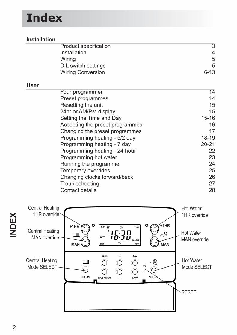
Index
Installation Product specifi cation 3 Installation 4 Wiring 5 DIL switch settings 5 Wiring Conversion 6-13
User Your programmer 14 Preset programmes 14 Resetting the unit 15 24hr or AM/PM display 15 Setting the Time and Day 15-16 Accepting the preset programmes 16 Changing the preset programmes 17 Programming heating - 5/2 day 18-19 Programming heating - 7 day 20-21 Programming heating - 24 hour 22 Programming hot water 23 Running the programme 24 Temporary overrides 25 Changing clocks forward/back 26 Troubleshooting 27 Contact details 28
Central Heating1HR override
Central HeatingMAN override
RESET
Central Heating Mode SELECT
+1HR
MAN
+1HR
MAN
Hot Water1HR override
Hot WaterMAN override
Hot WaterMode SELECT
IND
EX
3
Inst
alla
tion
& S
pecifi c
atio
n
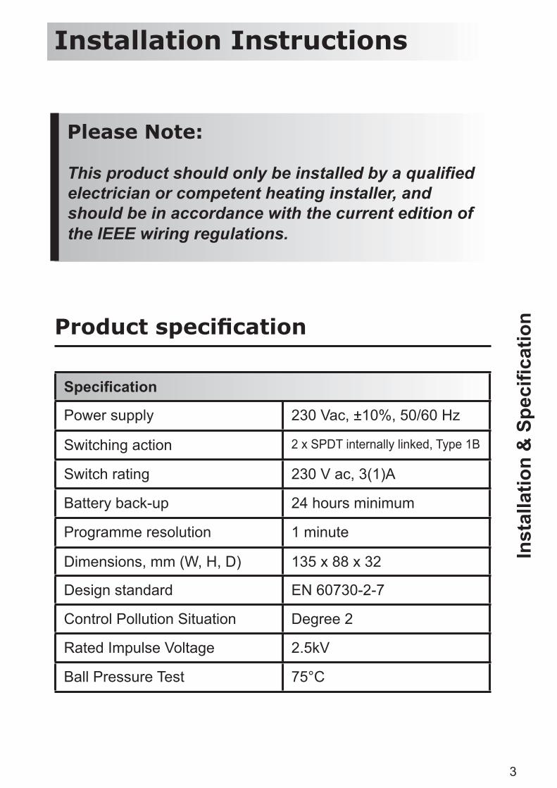
Please Note:
This product should only be installed by a qualifi ed electrician or competent heating installer, and should be in accordance with the current edition of the IEEE wiring regulations.
Specifi cation
Power supply 230 Vac, ±10%, 50/60 Hz
Switching action 2 x SPDT internally linked, Type 1B
Switch rating 230 V ac, 3(1)A
Battery back-up 24 hours minimum
Programme resolution 1 minute
Dimensions, mm (W, H, D) 135 x 88 x 32
Design standard EN 60730-2-7
Control Pollution Situation Degree 2
Rated Impulse Voltage 2.5kV
Ball Pressure Test 75°C
Product specifi cation
Installation Instructions
4
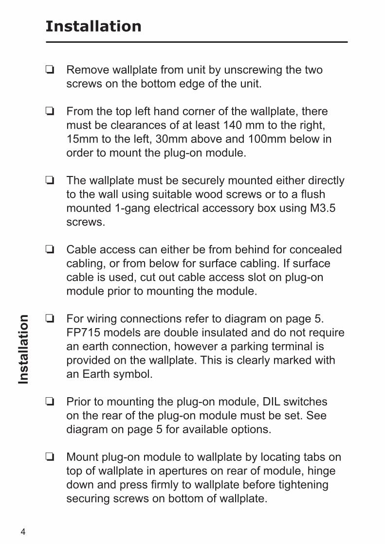
Installation
Remove wallplate from unit by unscrewing the two screws on the bottom edge of the unit.
From the top left hand corner of the wallplate, there must be clearances of at least 140 mm to the right, 15mm to the left, 30mm above and 100mm below in order to mount the plug-on module.
The wallplate must be securely mounted either directly to the wall using suitable wood screws or to a fl ush mounted 1-gang electrical accessory box using M3.5 screws.
Cable access can either be from behind for concealed cabling, or from below for surface cabling. If surface cable is used, cut out cable access slot on plug-on module prior to mounting the module.
For wiring connections refer to diagram on page 5. FP715 models are double insulated and do not require
an earth connection, however a parking terminal is provided on the wallplate. This is clearly marked with an Earth symbol.
Prior to mounting the plug-on module, DIL switches on the rear of the plug-on module must be set. See diagram on page 5 for available options.
Mount plug-on module to wallplate by locating tabs on top of wallplate in apertures on rear of module, hinge down and press fi rmly to wallplate before tightening securing screws on bottom of wallplate.
Inst
alla
tion

5
CP715 FP715 (3028 12/01)
2 O
N/O
FF
s
PU
MP
ED
7 D
AY
or
24 H
OU
R
24 H
OU
R
3 O
N/O
FF
s
GR
AV
ITY
5/2
DA
Y
7 D
AY
SW
.1
SW
.2
SW
.3
SW
.4
Wiri
ng &
DIL
sw
itch
setti
ngs
Wiring
Always switch off mains fi rst and never fi t programmer to a live wallplate.
For Wiring Conversion tables see - pages 6-13
Remember to tick the INSTALLER SETTING box on
the inside fl ap label to notify user in which
mode their unit is set (24hr, 5/2
day or 7 day).
DIL Switch Settings
Before mounting the unit, ensure the 4 DIL switches on the rear of the unit have been moved to the required settings
!INSTALLER SETTING24 Hour5+2 Day7 Day

6
WIRING CONVERSIONS Wiring conversions can be used when replacing the following programmers with the FP715. Some time controls are connected differently depending on the type of system they are controlling. Consult the column headed “NOTE
Table A
DANFOSS RANDALL FP715, CP715 (PUMPED)
MAINS DHW OFF
HTG OFF
DHW ON
N L 1 2 3
DANFOSS RANDALL 922/972 N L 1 4 3
DANFOSS RANDALL 4033 7 6 5 3 4
DANFOSS RANDALL SET 5 N L 3 6 1
HORSTMANN 423, AMETHYST 7 & 10 2,3 1 4 6 5
HORSTMANN 424 GEM 2,3 1,10 6 9 4
HORSTMANN LEUCITE 423 & 424 2 1 4 8 3
HORSTMANN 425 DIADEM N L 3 6 1
HORSTMANN 525 & 527 N L 3 6 1
HONEYWELL ST669 N L 7 4 6
HONEYWELL ST6300 & ST6400 N L 1 2 3
PEGLER SUNVIC SP50/SP100 N L 1 4 2
POTTERTON EP2000, EP3000 N L 1 2 3
RANDALL TSR3+3 3,6 7 2 5 1
RANDALL 3033 1,7 6 5 3 4
RANDALL 702 N L 4 2 3
SANGAMO FORM 1 410 & 414 4,5 6 2 7 1
SANGAMO S409/1 N,1,3 L - - 2

7
This conversion ...” to determine whether Table A (pages 6-9) or Table B (pages 10-13) should be used. If in any doubt, contact our Technical Services Department before proceeding with the replacement. *Any wires connected to switch COMMONS which are linked LIVE on existing wallplates must be transferred to the LIVE terminal on the new wallplate.
HTG ON
Wires other than links in these
terms got to LIVE
NOTEThis conversion applies only if....
An additional terminal block may be required where these discon-
nected leads (or pairs) should be terminated
4 L L A B C D
6 2 5 Programmed selectors UNLINKED
2 1 -
4 2 5
7 - - 8
7 5 8 Terminals 5,8 & 10 are LINKED
6 5 7 Terminals 5 & 7 are LINKED
4 2 5 Programme selectors UNLINKED
4 2 5 Programme selectors UNLINKED
3 8 5
4 - -
5 3 - S S
4 - 5 Programme selectors UNLINKED A B C D
4 - -
2 - -
1 6 5
8 3 -
5 - -
8
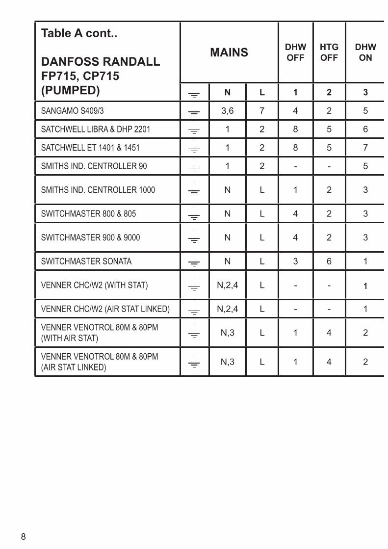
Table A cont..
DANFOSS RANDALL FP715, CP715 (PUMPED)
MAINS DHW OFF
HTG OFF
DHW ON
N L 1 2 3
SANGAMO S409/3 3,6 7 4 2 5
SATCHWELL LIBRA & DHP 2201 1 2 8 5 6
SATCHWELL ET 1401 & 1451 1 2 8 5 7
SMITHS IND. CENTROLLER 90 1 2 - - 5
SMITHS IND. CENTROLLER 1000 N L 1 2 3
SWITCHMASTER 800 & 805 N L 4 2 3
SWITCHMASTER 900 & 9000 N L 4 2 3
SWITCHMASTER SONATA N L 3 6 1
VENNER CHC/W2 (WITH STAT) N,2,4 L - - 1
VENNER CHC/W2 (AIR STAT LINKED) N,2,4 L - - 1
VENNER VENOTROL 80M & 80PM (WITH AIR STAT) N,3 L 1 4 2
VENNER VENOTROL 80M & 80PM (AIR STAT LINKED) N,3 L 1 4 2
9
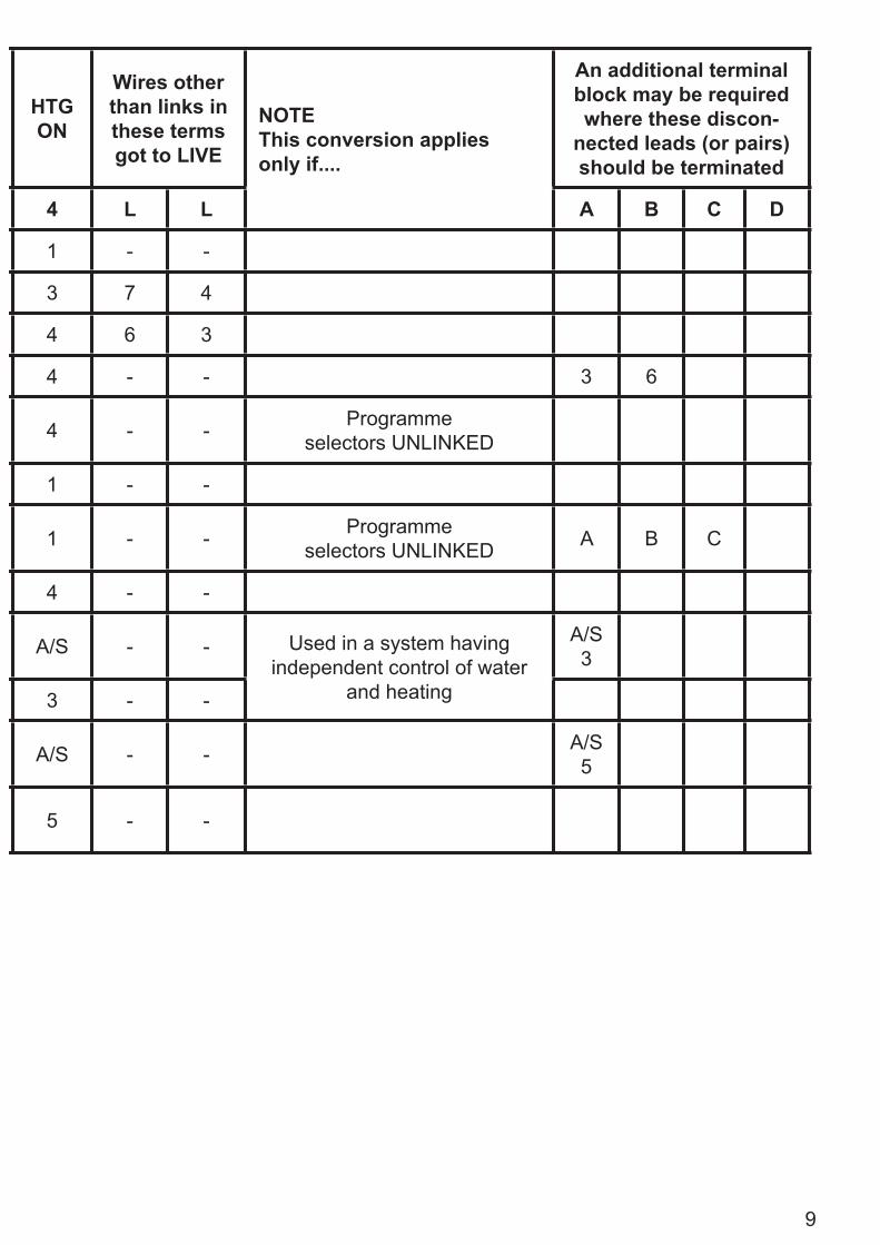
HTG ON
Wires other than links in these terms got to LIVE
NOTEThis conversion applies only if....
An additional terminal block may be required where these discon-
nected leads (or pairs) should be terminated
4 L L A B C D
1 - -
3 7 4
4 6 3
4 - - 3 6
4 - - Programme selectors UNLINKED
1 - -
1 - - Programme selectors UNLINKED A B C
4 - -
A/S - - Used in a system having independent control of water
and heating
A/S 3
3 - -
A/S - - A/S 5
5 - -
10
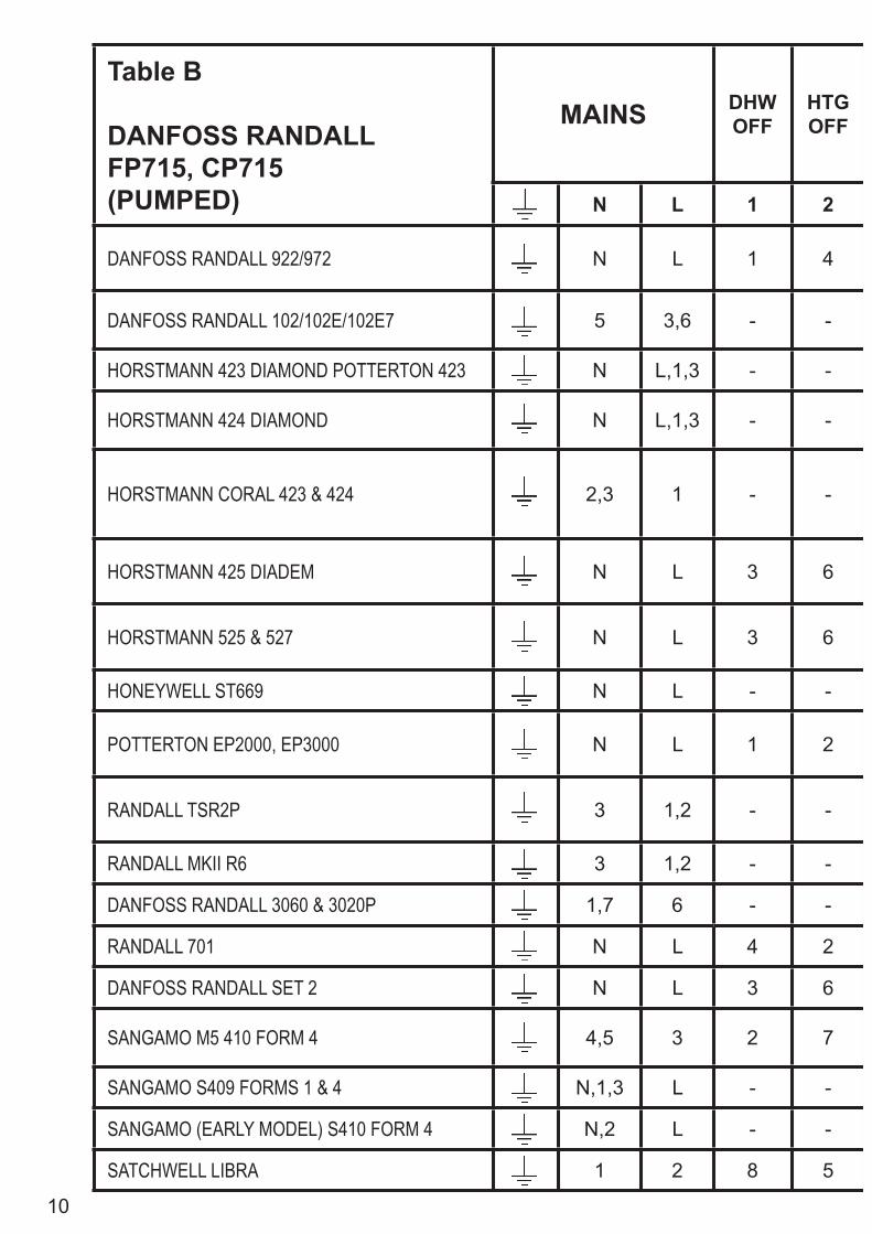
Table B
DANFOSS RANDALL FP715, CP715 (PUMPED)
MAINS DHW OFF
HTG OFF
N L 1 2
DANFOSS RANDALL 922/972 N L 1 4
DANFOSS RANDALL 102/102E/102E7 5 3,6 - -
HORSTMANN 423 DIAMOND POTTERTON 423 N L,1,3 - -
HORSTMANN 424 DIAMOND N L,1,3 - -
HORSTMANN CORAL 423 & 424 2,3 1 - -
HORSTMANN 425 DIADEM N L 3 6
HORSTMANN 525 & 527 N L 3 6
HONEYWELL ST669 N L - -
POTTERTON EP2000, EP3000 N L 1 2
RANDALL TSR2P 3 1,2 - -
RANDALL MKII R6 3 1,2 - -
DANFOSS RANDALL 3060 & 3020P 1,7 6 - -
RANDALL 701 N L 4 2
DANFOSS RANDALL SET 2 N L 3 6
SANGAMO M5 410 FORM 4 4,5 3 2 7
SANGAMO S409 FORMS 1 & 4 N,1,3 L - -
SANGAMO (EARLY MODEL) S410 FORM 4 N,2 L - -
SATCHWELL LIBRA 1 2 8 5

11
DHW ON
HTG ON
Wires other than links in these terms got to LIVE
NOTEThis conversion applies only if....
An additional terminal block may be required where these discon-
nected leads (or pairs) should be terminated
3 4 L L A B C D
3 6 2 5 Programmed selectors UNLINKED
1 2 - -
2 4 - - 5 6
2 4 - - 5
BOILER (8)
AIR STAT
(8)- - 4,7 5 6
1 4 2 5 Programme selectors UNLINKED
1 4 2 5 Programme selectors UNLINKED
8 7,3 6 5 ...set for gravity HW
3 4 - 5 Programme selectors UNLINKED A B C D
5,6 7 - - 1 & 2 are LINKED5 & 6 are LINKED 4
4 5 - - 6 7
4 2 - - 3 5
3 1 6 5
1,5 4 2 - With Links L-2 & 1-5
1,6 8 - - 1 & 6 are LINKED
2 5 - - 6,4
1,3 4 - - 1 & 3 are LINKED
6 3 7 4

12
Table B cont...
DANFOSS RANDALL FP715, CP715 (PUMPED)
MAINS DHW OFF
HTG OFF
N L 1 2
SMITHS IND. CENTROLLER 1000 N L - -
SMITHS IND. CENTROLLER 60 1 2 - -
SMITHS IND. CENTROLLER 10 N L - -
SMITHS IND. CENTROLLER 70 1 2 - -
SMITHS IND. CENTROLLER 1000 N L 1 2
SWITCHMASTER 320 & 350 N 4,L - -
SWITCHMASTER 400 N L - 4
SWITCHMASTER 600 N L - -
SWITCHMASTER 900 & 9000 N L 4 2
VENNER VENTROL N,A,M L,L,1 - -
VENNER VENOTROL 80 (AIR STAT) N,1,3,4 L - -
VENNER VENOTROL 80 (AIR STAT LINKED) N,13,4 L - -
VENNER CHC/W2 (WITH STAT) N,2,4 L - -
VENNER CHC/W2 (AIR STAT LINKED) N,2,4 L - -
VENNER VENOTROL 80P (WITH AIR STAT) N,1,3 L - 4
VENNER VENETROL 80P (AIR STAT LINKED) N,1,3 L - 4
13
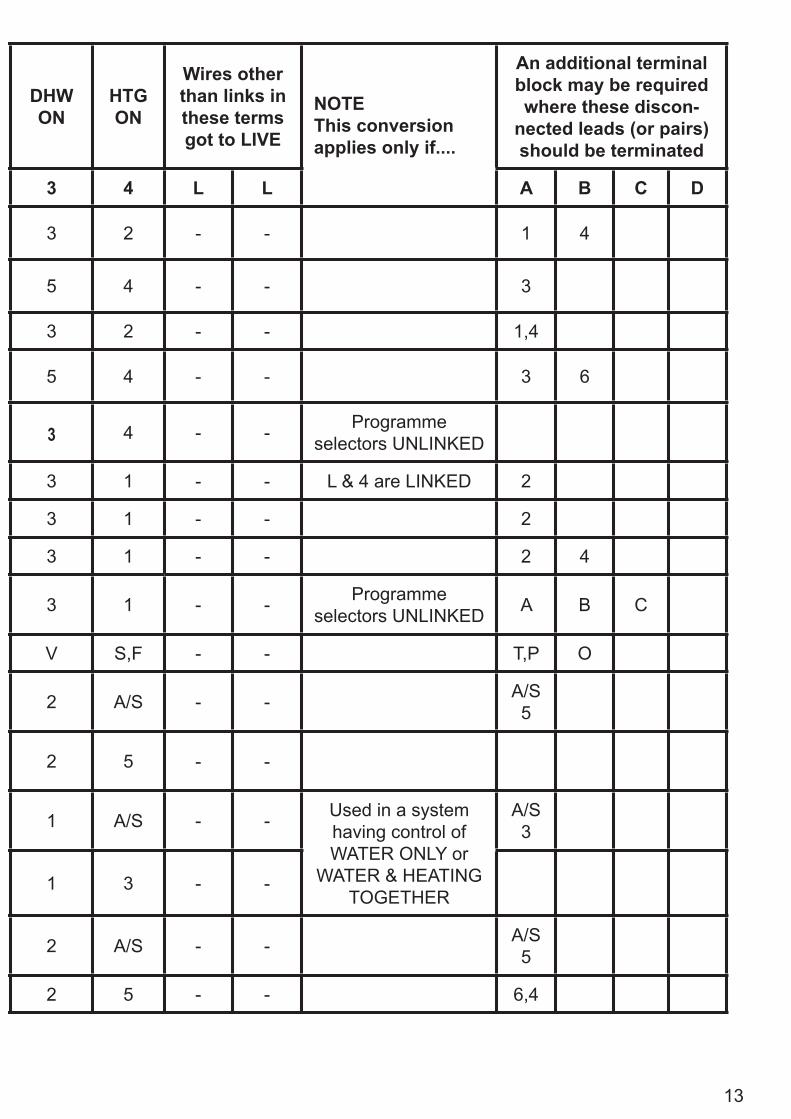
DHW ON
HTG ON
Wires other than links in these terms got to LIVE
NOTEThis conversion applies only if....
An additional terminal block may be required where these discon-
nected leads (or pairs) should be terminated
3 4 L L A B C D
3 2 - - 1 4
5 4 - - 3
3 2 - - 1,4
5 4 - - 3 6
3 4 - - Programme selectors UNLINKED
3 1 - - L & 4 are LINKED 2
3 1 - - 2
3 1 - - 2 4
3 1 - - Programme selectors UNLINKED A B C
V S,F - - T,P O
2 A/S - - A/S 5
2 5 - -
1 A/S - - Used in a system having control of WATER ONLY or
WATER & HEATING TOGETHER
A/S 3
1 3 - -
2 A/S - - A/S 5
2 5 - - 6,4

14
User Instructions
Your programmer
The FP715 allows you to switch your heating and hot water on and off at times that suit you.
You can programme up to 3 ON/OFF times per day for the heating and the hot water and the two systems can be operated independently.
Preset Programmes
Your FP715 comes ready programmed with a set of operating times which often suit most people.
If you want to change any of these settings, you can do so by following the instructions on pages 17-23. First, follow the steps on page 15-16 to set the correct time and date.
Ove
rvie
w &
Pre
set P
rogr
amm
es
Event No.Hot Water &
Heating Mon-Fri Sat-Sun**
1 1st ON 6:30 7:30
2 1st OFF 8:30 10:00
3* 2nd ON* 12:00* 12:00*
4* 2nd OFF* 12:00* 12:00*
5 3rd ON 17:00 17:00
6 3rd OFF 22:30 22:30
* Not applicable if unit set to 2 ON/OFFs per day by installer**Not applicable if unit set to 24 hour mode by installerSee page 17 for explanations of different settings

15
RES
ET, 2
4hr o
r AM
/PM
dis
play
, Set
ting
Tim
e
Before you start
This will reinstate the preset programmes and set the time to 12.00pm on Monday (MO)
Press and hold DAY & NEXT ON/OFF for 1.5 seconds to toggle between 24hr clock and AM/PM display, as required.
SETTING THE TIME
Press PROG once.
The words SET TIME will appear at the top of the display & the time will fl ash on and off.
Use the + and - buttons to set the correct time (press and hold to change in 10 min increments).
Setting the correct Time and Day
Choice of 24hr or AM/PM display
Open the fl ap on the front of the clock. Press the RESET button using a non-metallic object (e.g. pencil/matchstick) until you hear a click and the 2 red lights on the front of the unit fl ash once.
16
�
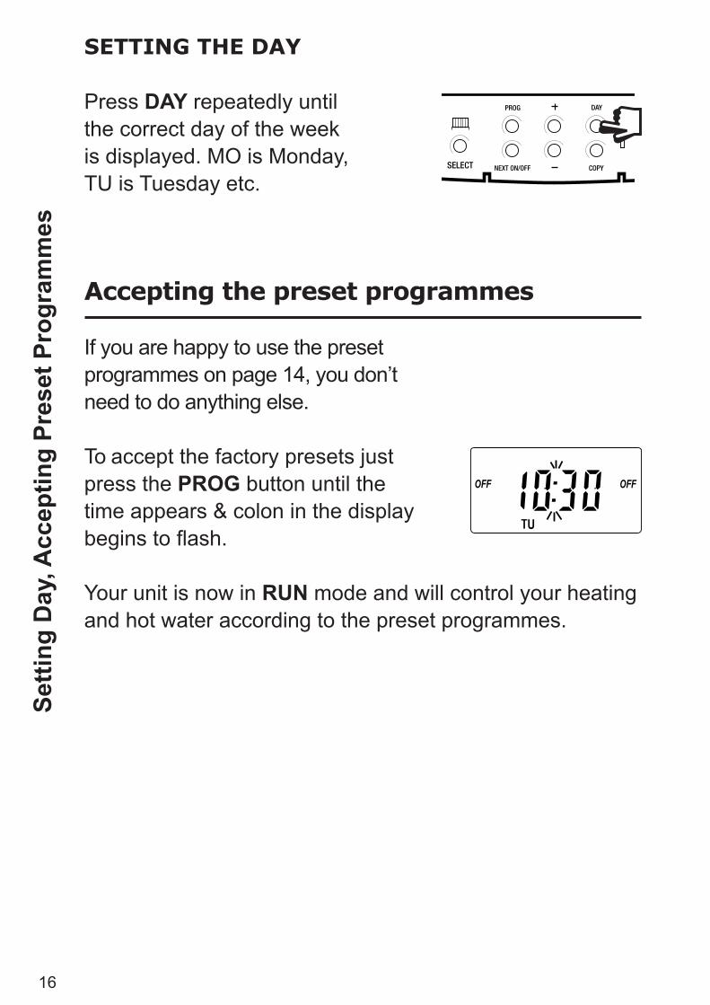
SETTING THE DAY
Press DAY repeatedly until the correct day of the week is displayed. MO is Monday, TU is Tuesday etc.
Accepting the preset programmes
If you are happy to use the preset programmes on page 14, you don’t need to do anything else.
To accept the factory presets just press the PROG button until the time appears & colon in the display begins to fl ash.
Your unit is now in RUN mode and will control your heating and hot water according to the preset programmes.
Setti
ng D
ay, A
ccep
ting
Pres
et P
rogr
amm
es
17
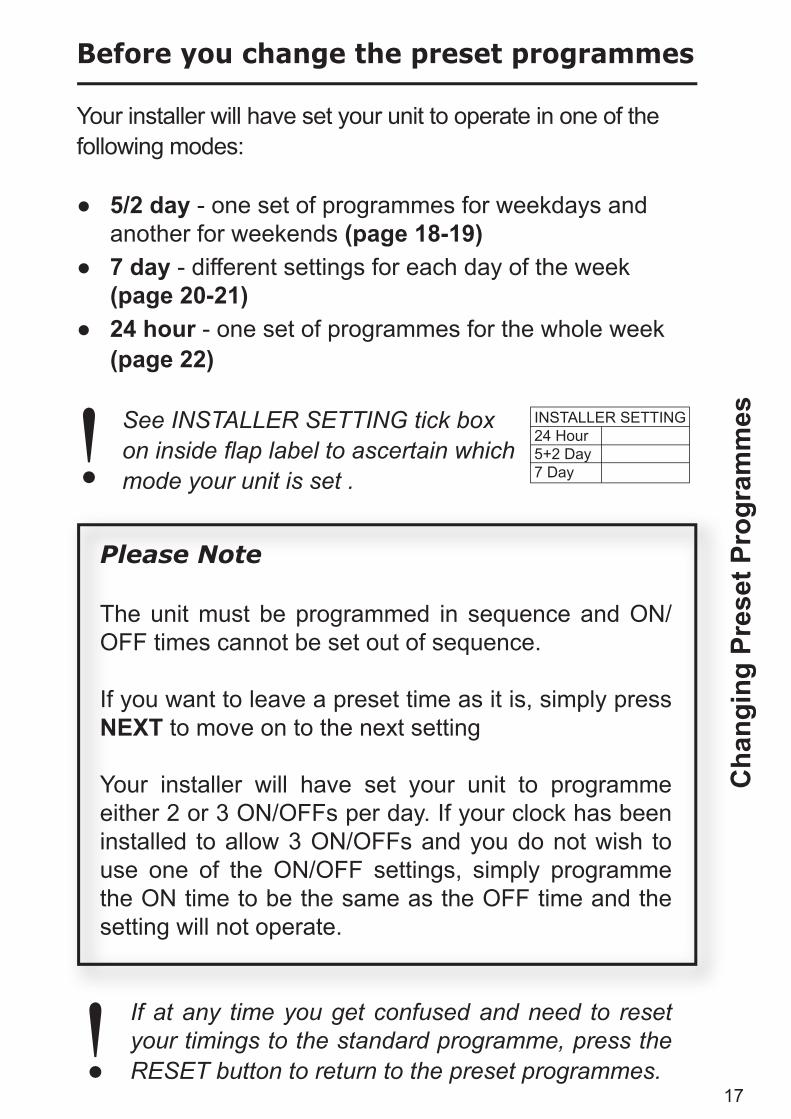
Before you change the preset programmes
Your installer will have set your unit to operate in one of the following modes:
● 5/2 day - one set of programmes for weekdays and another for weekends (page 18-19)
● 7 day - different settings for each day of the week (page 20-21)
● 24 hour - one set of programmes for the whole week (page 22)
See INSTALLER SETTING tick box on inside fl ap label to ascertain which mode your unit is set .
Cha
ngin
g Pr
eset
Pro
gram
mes
Please Note
The unit must be programmed in sequence and ON/OFF times cannot be set out of sequence. If you want to leave a preset time as it is, simply press NEXT to move on to the next setting
Your installer will have set your unit to programme either 2 or 3 ON/OFFs per day. If your clock has been installed to allow 3 ON/OFFs and you do not wish to use one of the ON/OFF settings, simply programme the ON time to be the same as the OFF time and the setting will not operate.
If at any time you get confused and need to reset your timings to the standard programme, press the RESET button to return to the preset programmes.!
INSTALLER SETTING24 Hour5+2 Day7 Day!

18
Programming the heating in 5/2 day mode
1. Press PROG until SET CH ON TIME appears at the top of the display and MOTUWETHFR appears at the bottom of the display.
Use the + and - buttons to set the time you would like your heating to fi rst come on in the morning (Event 1).
2. Press NEXT ON/OFF once only.
Use the + and - buttons to set the time you want your heating to go off (Event 2).
To move to the next setting, i.e. when you would like your heating to come on again (Event 3) press the NEXT ON/OFF button again.
3. Continue programming the central heating ON and OFF times for weekday Events 4, 5 & 6 as in Step 2.
Prog
ram
min
g he
atin
g - 5
/2 d
ay m
ode

19
4. Press the DAY button once and SASU will appear at the bottom of the display.
You can press COPY to keep the same settings for Saturday and Sunday as you have programmed for Monday to Friday.
Alternatively, programme new
ON/OFF times by pressing the NEXT ON/OFF button to move to the next setting and using the + and - buttons to set the time you want.
5. Press the PROG button to return the unit to RUN mode (time appears & colon in the display begins to fl ash)
6. Proceed to page 23. Pr
ogra
mm
ing
heat
ing
- 5/2
day
mod
e

20
1. Press PROG until SET CH ON TIME appears at the top of the display and MO appears at the bottom of the display.
Use the + and - buttons to
set the time you want your heating to fi rst come on in the morning (Event 1).
2. Press NEXT ON/OFF to move to Event 2.
Continue programming the central heating ON and OFF times in this way by using the + and - buttons to set the time you want and pressing the NEXT ON/OFF button to move to the next setting.
3. Press DAY button once
only. TU will appear at the bottom of the display.
Programming the heating in 7 day mode
Prog
ram
min
g he
atin
g - 7
day
mod
e

21
Continue programming the rest of the week by pressing:
a) NEXT ON/OFF button to move to the next setting,
b) + and - buttons to amend
the time
c) DAY to advance to the next day.
Alternatively press COPY to keep the same settings as the day before
4. Press the PROG button to return the unit to RUN mode (time appears & colon in the display begins to fl ash)
5. Proceed to page 23. Pr
ogra
mm
ing
heat
ing
- 7 d
ay m
ode

22
Prog
ram
min
g he
atin
g - 2
4 ho
ur m
ode
1. Press PROG until SET CH ON TIME appears at the top of the display.
Use the + and - buttons to set the time you want your heating to fi rst come on in the morning (Event 1).
2. Press NEXT ON/OFF to move to Event 2.
Continue programming the central heating ON and OFF times by pressing:
a) NEXT ON/OFF button to move to the next setting,
b) + and - buttons to amend
the time
3. Press the PROG button to return the unit to RUN mode (time appears & colon in the display begins to fl ash)
4. Proceed to page 23.
Programming the heating in 24 hour mode

23
Prog
ram
min
g ho
t wat
er
To set the hot water programme press the PROG button untilSET HW ON TIME appears on the display.
Set the hot water programme in the same way as the heating programme, using:
a) + and - buttons to alter the time
b) pressing the NEXT ON/OFF button to move to the next setting
c) pressing DAY to advance
through days of the week (7 day mode) or to advance
to Saturday and Sunday programming (5/2 day mode).
Finally press PROG to return the unit to run mode (time appears & colon in the display begins to fl ash).
Programming the hot water
24
���
��
������
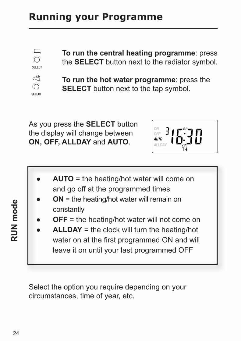
Running your Programme
To run the central heating programme: press the SELECT button next to the radiator symbol.
To run the hot water programme: press the SELECT button next to the tap symbol.
As you press the SELECT button the display will change between ON, OFF, ALLDAY and AUTO.
● AUTO = the heating/hot water will come on and go off at the programmed times● ON = the heating/hot water will remain on constantly● OFF = the heating/hot water will not come on● ALLDAY = the clock will turn the heating/hot water on at the fi rst programmed ON and will leave it on until your last programmed OFF
Select the option you require depending on your circumstances, time of year, etc.
RU
N m
ode

25
+1HR
MAN
+1HR
MAN
The grey buttons next to the radiator symbol are the Heating override buttons
The grey buttons next to the tap symbol are the Hot Water override buttons
+1HR = pressing this button when either system is in AUTO or ALLDAY mode will cause the heating/hot water to remain on for an extra hour. If it is pressed while the programme is OFF the heating/hot water will come on immediately for 1 hour then go off again.
MAN = pressing this button when either system is in
AUTO or ALLDAY mode will cause the heating/hot water to go OFF until the next programmed ON, or vice versa.
Temporary override buttons
Ove
rrid
e bu
ttons
Sometimes you may need to change the way you use your heating temporarily, i.e. due to unusually cold weather. The FP715 has two convenient overrides which can be selected without affecting the set programme.
+1HR
MAN
+1HR
MAN

26
Open the fl ap on the front of the unit to reveal the programming buttons.
To change from Summer to Winter (clocks back) -
press and hold - button
To change from Winter to Summer (clocks forward) -
press and hold + button
NOTE: After the fi rst time this change has been made this feature will only allow the clock to be changed in the opposite direction.
Changing clocks forward & back
!
Cha
ngin
g C
lock
s fo
rwar
d &
bac
k (S
umm
er/W
inte
r)
Take care when making this change for the fi rst time. If it is made in the wrong direction the unit will have to be reset
and any user-settings re-entered
(see pages 15-16 on how to Reset the unit and how to set the Time and Day).

27
�� ��� ����
����� ��� � �� ���� � �� � ��� ������� ������� �� ��� ��� ��� ���� ������� �� ���
�� ��� �� ����� � ��� ���� ������ ��! """ �� " ����� #��� �� #���� ���
"""""" $�� " ����� � ����� ��� ������
�� ��� ���� ��� �� � ����� ��� � �# %&'�! "" �� " �� � ���� �� %&'�
"""""" $�� " ����� �����
�� ��� ����� ��! """"" �� " ����� ��� ����� ��� ������
"""""" $�� " (��� ������ �� ��� �� )� �����
*�� ����� ���� �� ��+���� "" �� ����� ��! " �� " ����� ��� ���� ������
"""""" $�� " (��� ������ �� ��� �� )� �����
���� ��� ����� ���� ������ �� " ,�� ����� �����!" ��
"""""" $�� " (��� ������ �� ��� �� -& �����
��������� �� ����� .������ /������
0#�� ��� ���� ��� ���� ������1 ��� � ��� � �� ���� ��� ���� ���� ��� �� ��� �2�� �� ���������
�� ������
����� ��� � �� ���� � �� � ��� ���� ������� �� ��� ��� ��� ������� ������� �� ���
�� ��� �� ����� � ��� ������� ������ ��! "" �� " ����� #��� �� #���� ���
"""""" $�� " ����� ��� ��� ������
�� ����� ����� ��� ����� ���� ��� ����! "" �� " *�� ���� �� 3&'�
"""""" $�� " ����� �����
�� ��� ����� ��! """"" �� " ����� ����� ��� ������ �� ��� �� ��+�
"""""" $�� " 4������ � ������ �� ��� �� )� �����
*�� ����� ���� �� ��+���� �� ����� ��! "" �� " ����� ��� ���� ������
"""""" $�� " 4������ � ������ �� ��� �� )� �����
���� ��� ����� ���� ������ �� " ,�� ����� �����! " ��
"""""" $�� " 4������ � ������ �� ��� �� -& �����
��������� �� ����� .������ /������
0#�� ��� ������� ��� ���� ���� ��1 ��� � ��� � �� ���� ��� ���� ���� ��� �� ��� �2�� �� ���������
Fault Check List
Trou
bles
hoot
ing

Danfoss Randall LtdAmpthill RoadBedfordMK42 9ERTel: 01234 364621Fax: 01234 219705
Still having problems?
Call your local heating engineer:
Name:
Tel:
Visit our website:
www.danfoss-randall.co.uk
Email our technical department:
Call our technical department
0845 121 7505(8.45-5.15 Mon-Thurs, 8.45-4.45 Fri)
For a large print version of these instructions please contact the Marketing Services Department on 0845 121 7400.
Part No 38065 Issue 4 12/05