damage tolerance of cemented carbides under service-like
TRANSCRIPT
Damage tolerance of cemented carbides under service-like conditions
A dissertation submitted to partial fulfilment of the requirements for the degree of
Doctor of Philosophy by
José Maria Tarragó
Department of Materials Science and Metallurgical Engineering Doctorate program in Materials Science and Engineering
Universitat Politècnica de Catalunya – Barcelona Tech
Advisor: Luis Miguel Llanes
Barcelona, Spain September 2016

Cover photo: FESEM micrograph corresponding to unstable crack growth under monotonic loading for Co-base hardmetals. The image corresponds to a serial section obtained with the FIB/FESEM system. Back cover photo: FESEM micrograph corresponding to stable crack growth under cyclic loads for Co-base hardmetals. The image corresponds to a serial section obtained with the FIB/FESEM system.

Acta de qualificació de tesi doctoral Curs acadèmic:
Nom i cognoms
Programa de doctorat
Unitat estructural responsable del programa
Resolució del Tribunal Reunit el Tribunal designat a l'efecte, el doctorand / la doctoranda exposa el tema de la seva tesi doctoral titulada
“Damage tolerance of cemented carbides under service-like conditions”_________________________________
_________________________________________________________________________________________.
Acabada la lectura i després de donar resposta a les qüestions formulades pels membres titulars del tribunal,
aquest atorga la qualificació:
NO APTE APROVAT NOTABLE EXCEL·LENT
(Nom, cognoms i signatura) President/a
(Nom, cognoms i signatura) Secretari/ària
(Nom, cognoms i signatura) Vocal
(Nom, cognoms i signatura) Vocal
(Nom, cognoms i signatura) Vocal
______________________, _______ d'/de __________________ de _______________
El resultat de l’escrutini dels vots emesos pels membres titulars del tribunal, efectuat per l’Escola de Doctorat, a
instància de la Comissió de Doctorat de la UPC, atorga la MENCIÓ CUM LAUDE:
SÍ NO
(Nom, cognoms i signatura) President de la Comissió Permanent de l’Escola de Doctorat
(Nom, cognoms i signatura) Secretari de la Comissió Permanent de l’Escola de Doctorat
Barcelona, _______ d'/de ____________________ de _________


Damage tolerance of cemented carbides under service-like conditions III
Abstract
Cemented carbides, also referred to as hardmetals, are liquid-phase sintered composite materials
consisting of at least one hard and wear-resistant phase (WC in the majority of cases) embedded in a soft
and ductile metallic one from the iron group (being Co and its alloys the most widely used), acting as a
binder. Hardmetals exhibit an outstanding combination of hardness, wear resistance, strength and
toughness as a consequence of their fully interpenetrated two-phase structure. This unique combination of
properties has established cemented carbides at the forefront of a wide range of engineering and tooling
applications operating under extremely demanding service conditions. The key to success of cemented
carbides resides in their microstructure, which can be tailored to meet individual requirements for such a
range of applications; being the composition, content, size and distribution of the constituents the
principal microstructural parameters.
The current situation of hardmetal industry is strongly struggled by the high and volatile prices of
raw materials, owing that principal ore mines are located at places hardly accessible to the “industrial
world”. At this juncture, producers and end-users are deeply concerned in: (1) increasing the performance
and enhancing service-life and reliability of engineering products; (2) improving the efficiency of
recycling processes; and (3) replacing current constituents by alternative and less critical materials.
Within this context, premature and unexpected fracture, together with wear, is the main damage
phenomenon limiting the life in most cemented carbide applications. In the vast majority of cases such
ruptures stem from the combination of high monotonic and cyclic stresses, together with different
damage-related features associated with harsh service conditions, such as corrosion, impacts and thermal
shock. Therefore, relevant consideration of fracture toughness and fatigue resistance is required if
reliability (i.e. lower probability of premature and unexpected failures) and lifetime of hardmetal
engineering tools and components is to be increased. Following the above ideas, the purpose of this
thesis is to improve the performance and increase the reliability of cemented carbides in rupture-
limited applications on the basis of enhanced damage tolerance and reduced fatigue sensitivity
through an optimal microstructural design. Within this framework, this investigation is composed of
three main subjects covering different aspects related to the performance of hardmetals under service-like

IV Damage tolerance of cemented carbides under service-like conditions conditions. The first two sections are devoted to conduct a comprehensive study on the influence of the
microstructure on fracture and fatigue behaviour of hardmetals. The aim of the third section is to evaluate
microstructural effects on the tolerance of cemented carbides to service-like damage, induced either by
localised corrosion or thermal shock.
Main contribution to toughness in cemented carbides derives from plastic stretching of crack-
bridging ductile enclaves at the crack wake, referred to as the multiligament zone [1,2]. Hence, the
development of a multiligament zone implies the existence of a rising crack growth resistance (R-curve)
behaviour, the size of which is dependent on the width and strength of the ligaments; and thus, on the
microstructural arrangement. In toughened materials, damage tolerance is successfully promoted with the
development of R-curve behaviour. Therefore, higher reliability and strength enhancement can be
attained by building microstructures capable of developing toughening mechanisms so that strength
becomes less sensitive to flaw size [3]. The main advantage of such strategy is that it permits to allocate
appreciable service-damage without compromising the structural integrity of the component. In this
regard, the first section of this thesis is dedicated to carry out a detailed investigation of fracture
mechanics and mechanisms in cemented carbides, and to propose a relation to capture
microstructural effects on the R-curve characteristics of these materials. This section also includes a
study on the uniaxial compression behaviour of micropillars consisting of Co-binder ligaments
constrained by their surrounding WC carbides milled with focused ion beam (FIB). Main purpose of this
work is to bring insights on the mechanical deformation and failure behaviour of the constrained ductile
metallic ligaments and the carbide/binder interface as key features for determining effective toughening in
cemented carbides.
Strength reduction of hardmetals under the application of cyclic stresses is intimately related to the
inhibition of the crack-tip bridging mechanism [4]. For WC–Co cemented carbides, the degradation of
bridging ligaments is mainly associated with an accumulation of the fcc to hcp fatigue-induced
martensitic phase transformation [5]. However, this mechanism does not apply for Ni binders [6,7];
therefore, it remains unclear if effective fatigue susceptibility of Co-base hardmetals is comparable to that
of cemented carbides consisting of alternative binders. Moreover, hardmetals exhibit crack-deflection as
an additional toughening mechanism, but contrary to the case of crack-bridging, it is immune to fatigue
loads [8]. The effective action of this toughening mechanism is speculated to increase with rising carbide
mean grain size. Accordingly, it is also the goal of this thesis to assess the microstructural influence on
the effective toughening derived from crack-deflection in cemented carbides. Hence, the second part of
this thesis is devoted to study and understand the fatigue sensitivity of cemented carbides consisting
of binders with deformation mechanisms beyond phase transformation as well as medium/coarse
microstructures.

Damage tolerance of cemented carbides under service-like conditions V
As mentioned above, cemented carbides applications are generally subjected to harsh working
conditions. These derive in different damage mechanisms that limit their service-life. Within this context,
the third section of this thesis consists of a systematic study on the influence of the microstructure
on damage-related features induced by either thermal shock or corrosion, in order to set out
guidelines for optimal microstructural design. In doing so, (1) the structural integrity of damaged
cemented carbides is assessed on the basis of residual strength; (2) microstructural effects on damage
tolerance are captured by means of considering induced damage level as a critical parameter; and (3)
toughness and R-curve characteristics (previously determined) are assumed to be dominant properties for
enhanced performance. In addition, thermal shock resistance parameters for studied materials are
estimated and invoked as figures of merit for rationalizing structural design of cemented carbides
applications subjected to thermal shock.
Keywords: cemented carbides; alternative binders; fracture mechanics; fracture mechanisms; R-curve
behaviour; fatigue crack growth; fatigue life; fatigue mechanisms; crack-deflection; corrosion; thermal
shock; residual strength; damage tolerance; FIB/FESEM tomography; fractography

VI Damage tolerance of cemented carbides under service-like conditions

Damage tolerance of cemented carbides under service-like conditions VII
Preface
This dissertation includes the research work conducted by the author for obtaining the degree of
Doctor of Philosophy at the Universitat Politècnica de Catalunya – Barcelona Tech during the period
from the 5th of March 2012 to the 14th of September 2016. This Ph.D. thesis was carried out under the
supervision of Prof. Luis Miguel Llanes Pitarch at the Centre d'Integritat Estructural i Fiabilitat dels
Materials (CIEFMA) group from the Departament de Ciència dels Materials i Enginyeria Metal·lúrgica
(CMEM) of the Universitat Politècnica de Catalunya (UPC). The presented work is original, unless
otherwise detailed references are provided.
This Ph.D. thesis is presented as a compendium of published articles and contains eight chapters,
which are described hereafter. Chapter 1 describes the state of the art on cemented carbides and their
behaviour under service-like conditions. Chapter 2 summarizes the aims and scope of the thesis.
Experimental details are described in respective articles but some additional details on the microstructural
and mechanical characterization of studied materials as well as on the 3D FIB/FESEM tomography
technique are included in Chapter 3. In Chapter 4 the eight articles presented in this thesis are introduced
and classified in three main subject areas: (1) fracture behaviour of cemented carbides; (2) fatigue
mechanics and mechanisms of cemented carbides; and (3) structural integrity of cemented carbides
subjected to service-like damage induced either by corrosion or thermal shock. Full articles are included
in Chapters 5 to 7 according to their areas of study. Finally, the summary of the results, the conclusions
and the impact and future perspectives of the work are detailed in Chapter 8.

VIII Damage tolerance of cemented carbides under service-like conditions

Damage tolerance of cemented carbides under service-like conditions IX
List of publications
This Ph.D. thesis consists of a compendium of the articles presented in the following list. The term
IF refers to the impact factor, whereas Q indicates the quartile.
Article I. Tarragó JM, Jimenez-Piqué E, Turón-Viñas M, Rivero L, Al-Dawery I, Schneider L, Llanes L.
Fracture and fatigue behavior of cemented carbides: 3D Focused Ion Beam Tomography of crack-
microstructure interactions. International Journal of Powder Metallurgy 50, 1–10 (2014). IF 0.409, Q4
(58/74) in the category: “Metallurgy and Metallurgical Engineering”.
Article II. Tarragó JM, Roa JJ, Jiménez-Piqué E, Keown E, Fair J, Llanes L. Mechanical deformation of
WC–Co composite micropillars under uniaxial compression. International Journal of Refractory Metals
and Hard Materials 54, 70–74 (2016). DOI: 10.1016/j.ijrmhm.2015.07.015. IF 1.989, Q2 (86/260) in the
category: “Materials Science, Multidisciplinary” and Q1 (7/74) in the category: “Metallurgy and
Metallurgical Engineering”.
Article III. Tarragó JM, Jiménez-Piqué E, Schneider L, Casellas D, Torres Y, Llanes L. FIB/FESEM
experimental and analytical assessment of R-curve behavior of WC–Co cemented carbides. Materials
Science & Engineering A 645, 142–149 (2015). DOI: 10.1016/j.msea.2015.07.090. IF 2.567, Q1 (58/260)
in the category: “Materials Science, Multidisciplinary”, Q1 (5/74) in the category: “Metallurgy &
Metallurgical Engineering” and Q2 (36/80) in the category: “Nanoscience & Nanotechnology”.
Article IV. Tarragó JM, Coureaux D, Torres Y, Casellas D, Al-Dawery I, Schneider L and Llanes L,
Microstructural effects on the R-curve behavior of WC–Co cemented carbides, Materials & Design 97,
492–501 (2016). DOI: 10.1016/j.matdes.2016.02.115. IF 3.501, Q1 (43/260) in the category: “Materials
Science, Multidisciplinary”.

X Damage tolerance of cemented carbides under service-like conditions Article V. Tarragó JM, Ferrari C, Reig B, Coureaux D, Schneider L, Llanes L. Mechanics and
mechanisms of fatigue in a WC–Ni hardmetal and a comparative study with respect to WC–Co
hardmetals. International Journal of Fatigue 70, 252–257 (2015). DOI: 10.1016/j.ijfatigue.2014.09.011.
IF 2.275, Q1 (12/130) in the category: “Engineering, Mechanical” and Q2 (68/260) in the category:
“Materials Science, Multidisciplinary”.
Article VI. Tarragó JM, Roa JJ, Valle V, Marshall JM, Llanes L. Fracture and fatigue behavior of WC–
Co and WC–CoNi cemented carbides. International Journal of Refractory Metals and Hard Materials 49,
184–191 (2015). DOI: 10.1016/j.ijrmhm.2014.07.027. IF 1.989, Q2 (86/260) in the category: “Materials
Science, Multidisciplinary” and Q1 (7/74) in the category: “Metallurgy and Metallurgical Engineering”.
Article VII. Tarragó JM, Fargas G, Jimenez-Piqué E, Felip A, Isern L, Coureaux D, Roa JJ, Al-Dawery I,
Fair J, Llanes L. Corrosion damage in WC–Co cemented carbides: residual strength assessment and 3D
FIB-FESEM tomography characterisation. Powder Metallurgy 57, 324–330 (2014). DOI:
10.1179/1743290114Y.0000000115. IF 0.772, Q3 (38/74) in the category: “Metallurgy and Metallurgical
Engineering”.
Article VIII. Tarragó JM, Dorvlo S, Esteve J, Llanes L. Influence of the microstructure on the thermal
shock behavior of cemented carbides. Ceramics International 42, 12701–12708 (2016). DOI:
10.1016/j.ceramint.2016.05.024. IF 2.605, Q1 (4/26) in the category: “Materials Science, Ceramics”.

Damage tolerance of cemented carbides under service-like conditions XI
Contents
Abstract ....................................................................................................................................................... III
Preface ....................................................................................................................................................... VII
List of publications ......................................................................................................................................IX
Contents .......................................................................................................................................................XI
List of figures and tables ........................................................................................................................... XV
Figures ................................................................................................................................................... XV
Tables ................................................................................................................................................... XVI
Glossary of symbols and abbreviations .................................................................................................. XVII
Glossary of symbols ........................................................................................................................... XVII
Glossary of abbreviations ..................................................................................................................... XIX
Chapter 1. Introduction.................................................................................................................................. 1
1.1. Introduction to cemented carbides .................................................................................................... 1
1.1.1. History and current status of hardmetal industry ................................................................... 1
1.1.2. Structure of cemented carbides ............................................................................................. 4
1.1.3. Microstructure of WC–Co/Ni cemented carbides ................................................................. 7
1.1.4. Microstructure-property relations and applications ............................................................. 10
1.2. Fracture behaviour of cemented carbides ....................................................................................... 11
1.2.1. Fracture mechanics and mechanisms .................................................................................. 12
1.2.2. Fracture behaviour within the framework of Weibull statistics theory ............................... 16
1.3. Fatigue behaviour of cemented carbides ........................................................................................ 16
1.3.1. Strength degradation under the application of cyclic loads ................................................. 17
1.3.2. Fatigue crack growth behaviour .......................................................................................... 18
1.4. Service-like damage in cemented carbides ..................................................................................... 20
1.4.1. Corrosion behaviour ............................................................................................................ 21
1.4.2. Thermal shock resistance .................................................................................................... 23

XII Damage tolerance of cemented carbides under service-like conditions
1.5. Focused Ion Beam system .............................................................................................................. 25
1.5.1. 3D FIB/FESEM Tomography ............................................................................................. 25
Chapter 2. Aims and scope of the work ....................................................................................................... 27
2.1. Fracture behaviour of cemented carbides ....................................................................................... 27
2.2. Fatigue mechanics and mechanisms of cemented carbides ............................................................ 28
2.3. Damage tolerance of cemented carbides under service-like conditions: corrosion and thermal shock ........................................................................................................................................................ 29
Chapter 3. Experimental details .................................................................................................................. 31
3.1. Materials: nomenclature and microstructural characterization ....................................................... 31
3.2. Mechanical characterization ........................................................................................................... 32
3.3. 3D FIB/FESEM Tomography......................................................................................................... 33
Chapter 4. Articles presentation .................................................................................................................. 35
4.1. Fracture behaviour of cemented carbides ....................................................................................... 36
Article I. Fracture and fatigue behavior of cemented carbides: 3D Focused Ion Beam Tomography of crack-microstructure interactions ......................................................................... 37
Article II. Mechanical deformation of WC–Co composite micropillars under uniaxial compression .................................................................................................................................... 38
Article III. FIB/FESEM experimental and analytical assessment of R-curve behavior of WC–Co cemented carbides .......................................................................................................................... 39
Article VI. Microstructural effects on the R-curve behavior of WC–Co cemented carbides ......... 40
4.2. Fatigue mechanics and mechanisms in cemented carbides ............................................................ 41
Article V. Mechanics and mechanisms of fatigue in a WC–Ni hardmetal and a comparative study with respect to WC–Co hardmetals ................................................................................................ 42
Article VI. Fracture and fatigue behavior of WC–Co and WC–CoNi cemented carbides ............. 43
4.3. Structural integrity of cemented carbides subjected to service-like damage: corrosion and thermal shock ........................................................................................................................................................ 44
Article VII. Corrosion damage in WC–Co cemented carbides: residual strength assessment and 3D FIB-FESEM tomography characterisation ............................................................................... 45
Article VIII. Influence of the microstructure on the thermal shock behaviour of cemented carbides ........................................................................................................................................... 46
Chapter 5. Fracture behaviour of cemented carbides .................................................................................. 47
Article I. Fracture and fatigue behavior of cemented carbides: 3D Focused Ion Beam Tomography of crack-microstructure interactions ............................................................................................................ 49
Article II. Mechanical deformation of WC–Co composite micropillars under uniaxial compression .... 61
Article III. FIB/FESEM experimental and analytical assessment of R-curve behaviour of WC–Co cemented carbides ................................................................................................................................... 69
Article IV. Microstructural effects on the R-curve behaviour of WC–Co cemented carbides ................ 79

Damage tolerance of cemented carbides under service-like conditions XIII
Chapter 6. Fatigue mechanics and mechanisms in cemented carbides ....................................................... 91
Article V. Mechanics and mechanisms of fatigue in a WC–Ni hardmetal and a comparative study with respect to WC–Co hardmetals ................................................................................................................. 93
Article VI. Fracture and fatigue behavior of WC–Co and WC–CoNi cemented carbides .................... 101
Chapter 7. Structural integrity of cemented carbides subjected to service-like damage: corrosion and
thermal shock ............................................................................................................................................ 111
Article VII. Corrosion damage in WC–Co cemented carbides: residual strength assessment and 3D FIB-FESEM tomography characterisation ............................................................................................ 113
Article VIII. Influence of the microstructure on the thermal shock resistance of cemented carbides ... 123
Chapter 8. Results and conclusions ........................................................................................................... 133
8.1. Summary of the results and discussion ......................................................................................... 133
8.1.1. Fracture and fatigue processes in cemented carbides: crack-microstructure interactions . 133
8.1.2. Influence of the microstructure on the R-curve behaviour of cemented carbides: implications on strength and reliability ........................................................................................ 135
8.1.3. Response of WC–Co micropillars to uniaxial compression .............................................. 135
8.1.4. Fatigue sensitivity of hardmetals with Ni-containing binders ........................................... 136
8.1.5. Carbide mean grain size effects on crack-deflection ......................................................... 136
8.1.6. Damage tolerance of cemented carbides to localised corrosion: microstructural effects .. 137
8.1.7. Corrosion phenomena in cemented carbides ..................................................................... 137
8.1.8. Damage tolerance of cemented carbides to thermal shock: microstructural effects .......... 138
8.2. General conclusions ...................................................................................................................... 138
8.3. Impact and perspectives ............................................................................................................... 140
Acknowledgments ..................................................................................................................................... 143
Bibliography .............................................................................................................................................. 145
Annex 1. Microstructural influence on tolerance to corrosion-induced damage in hardmetals ................ 153
Annex 2. Additional Contributions ........................................................................................................... 171
Work presented in conferences ............................................................................................................. 171
Additional articles published in International Journals ......................................................................... 173

XIV Damage tolerance of cemented carbides under service-like conditions
Damage tolerance of cemented carbides under service-like conditions XV
List of figures and tables
Figures
Figure 1.1. Estimated worldwide production of hardmetals in the years from 1930 to 2011 [14,17].
Adapted image from [14]. ............................................................................................................................. 2
Figure 1.2. General application areas of cemented carbides by worldwide consumption and by turnover;
note the significant differences in share due to the strong differences in the degree of added value.
Adapted image from [18]. ............................................................................................................................. 3
Figure 1.3. (a) Example of the microstructure of a WC–10%wt.Co hardmetal and (b) vertical section of
the W–C–Co phase diagram calculated for a WC–10%wt.Co cemented carbide [23]. Image from [12]. ...... 4
Figure 1.4. (a) WC unit cell with unit lattice vectors: a1 = 1/3[2-1-10], a2 = 1/3[-12-10], and c = [0001].
Each tungsten atom is bounded to the six nearest carbon atoms forming two mirror-like triangular prisms
[25] and (b) schematic WC grain shape [26]. ................................................................................................ 5
Figure 1.5. Electron Backscattered Scanning Diffraction (EBSD) micrograph of (a) carbide and (b)
binder phases of a WC–11%wt.Co cemented carbide. Images from [27]. ...................................................... 6
Figure 1.6. Influence of the microstructure on the mechanical properties of cemented carbides: (a)
hardness, (b) wear resistance, (c) compressive strength and (d) fracture toughness of cemented carbides as
a function of the binder content for different carbide mean grain sizes. Image from [43]. ......................... 10
Figure 1.7. Application range of cemented carbides as a function of their WC grain size and cobalt
content. Image from [43]. ............................................................................................................................ 11
Figure 1.8. Nucleation, growth and coalescence of microcavities within the binder phase during crack
unstable propagation. Adapted image from [2]. .......................................................................................... 14
Figure 1.9. A schematic representation of crack-growth resistance curves for a material exhibiting a flat
and a rising R-curve. Image from [71]. ....................................................................................................... 15
Figure 1.10. (a) S–N curves for a representative hardmetal and cermet grades, and (b) correlation of the
slope of the S–N plots, as a measurement of fatigue sensitivity, with the mean free path of binder [85].
Images from [82]. ........................................................................................................................................ 18

XVI Damage tolerance of cemented carbides under service-like conditions Figure 1.11. Fatigue sensitivity and p/q ratio evolution as a function of the binder mean free path for
WC–Co cemented carbides [4]. Image from [82]. ...................................................................................... 20
Figure 1.12. Schematic presentation of the reactions taking place on the WC–Co surface. Image from
[108]. ........................................................................................................................................................... 21
Figure 1.13. Examples of full polarization scans measured for WC–6Co%wt. (square) and WC–
16.5Co%wt. (circles) cemented carbides. Image from [122]. ....................................................................... 22
Figure 8.1. FESEM micrographs corresponding to (a) unstable crack growth under monotonic loading
and (b) stable crack growth under cyclic loads for Co-base hardmetals. The top images correspond to
serial sections obtained by FIB/FESEM tomography whereas the bottom ones correspond to fractographic
micrographs. .............................................................................................................................................. 134
Tables
Table 1.1. Principal developments in the cemented carbide industry from the invention of the first WC–
Co tool [13,14,21,22]. .................................................................................................................................... 3
Table 1.2. Grain size classification of cemented carbides [12]. ................................................................... 8
Table 3.1. Specimen code, binder composition, additives, binder content, carbide mean grain size,
carbide contiguity and binder mean free path for the investigated cemented carbides. .............................. 32
Table 3.2. Hardness, flexural strength, Weibull characteristic strength, Weibull modulus and fracture
toughness values for the investigated cemented carbides. ........................................................................... 33
Table 4.1. Contribution statement of the author to the appended papers. Note that P.R. refers to “principal
role” and S.R. to “secondary role”. N/A= Not applicable. .......................................................................... 35

Damage tolerance of cemented carbides under service-like conditions XVII
Glossary of symbols and abbreviations
Glossary of symbols
a Crack length
ac Critical crack length
C Constant of proportionality on the Paris-Erdogan equation
CWC Contiguity of the carbide phase
dWC Carbide mean grain size
E Elastic modulus
HV30 Vickers hardness under the application of 30 kgf
KIc Plain strain fracture toughness
Kmax Maximum crack-tip stress intensity factor
Kmin Minimum crack-tip stress intensity factor
KR Crack-tip resistance stress intensity factor for crack propagation (R-curve)
Kt Critical crack-tip stress intensity factor required for crack initiation
Kth Fatigue crack growth threshold
m Weibull modulus
m’ Exponent of the Paris-Erdogan equation
N Number of cycles
NWC/binder Number of carbide/ binder interfaces
NWC/WC Number of carbide/carbide interfaces

XVIII Damage tolerance of cemented carbides under service-like conditions
p Exponent of the modified Paris-Erdogan equation corresponding to Kmax
Pf Probability of failure
q Exponent of the modified Paris-Erdogan equation corresponding to ΔK
R First Hasselman’s thermal shock resistance parameter referring to crack nucleation
r Load ratio
R’ Second Hasselman’s thermal shock resistance parameter referring to crack nucleation
R’’’’ Fourth Hasselman’s thermal shock resistance parameter referring to crack propagation
S Stress
S’ Shape factor
t Crack length normalising parameter for the description of R-curve behaviour
V Specimen volume
V0 Normalising volume
Vbinder Binder volume content
VWC Carbide volume content
Vwtbinder Binder weight content
α Carbide phase
αCTE Coefficient of thermal expansion
β Binder phase
Δa Subcritical crack growth under the application of monotonic loads
ΔK Stress intensity factor range
ΔTc Critical temperature difference
η Eta phase
λ Heat conductivity
λbinder Binder mean free path
ρc Composite density
ρWC Density of the carbide phase
σ0 Weibull characteristic strength
σapp Applied strength

Damage tolerance of cemented carbides under service-like conditions XIX
σf Fatigue limit
σr Fracture strength
υ Poisson ratio
Glossary of abbreviations
FIB Focused ion beam
SEM Scanning electron microscopy
FESEM Field emission scanning electron microscopy
fcc Face centred cubic
hcp Hexagonal close packed
PM Powder metallurgy
REACH European program for registration, evaluation, authorisation and restriction of chemical substances
NPT U.S. national toxicology program
EDM Electrical discharge machining
EBSD Electron backscatter diffraction
TEM Transmission electron microscopy
FCG Fatigue crack growth
SEPB Single edge pre-cracked beam

XX Damage tolerance of cemented carbides under service-like conditions

Damage tolerance of cemented carbides under service-like conditions 1
Chapter 1
Introduction
1.1. Introduction to cemented carbides
Cemented carbides, also called hardmetals, are a group of powder metallurgy (PM) liquid-phase-
sintered materials consisting of brittle refractory carbides of the transition metals (e.g. WC, TiC, TaC and
NbC) embedded in a metallic matrix that acts as a binder. The preferential choice for the binder is cobalt.
However, alternative binders, principally nickel and iron alloys, have also attracted considerable attention
as cobalt substitutes in certain applications. The key to success of cemented carbides resides in their
outstanding combination of strength, toughness and wear-resistance. Such remarkable mechanical
properties result from the extremely different properties of their two interpenetrating constitutive phases:
hard, brittle carbides and a soft, ductile metallic binder (e.g. Refs. [9–11]). As a consequence, they are
forefront materials in a wide range of extremely demanding applications, where high tribomechanical
performance and improved reliability are required, such as metal cutting, mining, rock drilling, metal
forming and wear parts [12].
1.1.1. History and current status of hardmetal industry
The starting point for the use of hardmetals in engineering applications dates from 1923, when Karl
Schröter successfully sintered for the first time a WC–Co hardmetal. Schröter’s main purpose was to
replace diamond in drawing dies to produce tungsten wires for incandescent lamps [13,14]. Three years
later, Krupp brought sintered carbides onto the market under the name of “WIDIA”. In short time
afterwards, cemented carbides started to replace high speed steels in cutting tools due to its superior hot
hardness and improved wear resistance [14,15]. This fact involved a drastically increase in cutting speeds,
resulting in important savings for machine tool industry. From that moment on, the field of application of
cemented carbides rapidly expanded; and in consequence worldwide hardmetal production has steady
increased during the last century, as can be seen in Figure 1.1 [14]. In 2008 world hardmetal production

2 Damage tolerance of cemented carbides under service-like conditions was about 60,000 tons and was estimated to be worth more than 10 billion euros [16]. Indeed, in 2011
worldwide tungsten consumption for cemented carbides reached 62,000 tons, which represent almost the
60% of worldwide tungsten consumption (including recycled material) [17]. Concretely, tungsten
consumption is growing extremely fast in China and nowadays it accounts for almost the 60% of world
consumption [17]. Stone working and machining of wood and plastics are the largest fields of application,
followed by metal cutting, wear applications and chipless forming. In contrast, metal cutting group
accounts for a 65% of the turnover (due to its high degree of innovation and added value), compared to
the other hardmetal sectors [18], as shown in Figure 1.2.
Figure 1.1. Estimated worldwide production of hardmetals in the years from 1930 to 2011 [14,17]. Adapted image from [14].
Since the discovery of the first WC–Co cemented carbide, performance enhancement has been
continuous and some of the most outstanding advances of the hardmetal industry are reflected in Table
1.1 [13]. Current developments in the field of hard materials are mainly related to the scarcity of raw
materials that results in high and volatile prices due that main ore mines are located in areas of difficult
access to the “industrial world” [16,17]. In addition, hardmetal industry has encountered an important
challenge from the health perspective. In fact, the European program for Registration, Evaluation,
Authorisation and Restriction of Chemical substances (REACH) [19] and the U.S. National Toxicology
Program (NTP) [20] have considered cobalt dust as a toxic and carcinogenic material [17]. Therefore,
significant efforts are being devoted to: minimize the use and/or replace raw materials, increase the
efficiency of recycling processes, and improve the performance and enhance the lifetime of cemented
carbide tools and components [17].
1
10
100
1000
10000
100000
Wor
ldw
ide
prod
uctio
n (to
ns)

Damage tolerance of cemented carbides under service-like conditions 3
Figure 1.2. General application areas of cemented carbides by worldwide consumption and by turnover; note the significant differences in share due to the strong differences in the degree of added value. Adapted image from [18].
Year Event
1923-1925 Invention of the first WC–Co tool
1929-1931 Development of WC–TiC–Co and WC–TaC(VC,NbC) –Co grades
1938 WC–Cr3C2–Co
1948-1970 Manufacturing of submicron WC–Co hardmetals
1965-1975 Hot Isostatic Pressing (HIP)
1965-1978 Application of CVD coatings on hardmetals tools like TiC, TiN and Al2O3
1969-1971 Thermochemical surface hardening
1970-1990 Powders recycled by the zinc process
1974-1977 Polycrystalline diamond on WC–base hardmetal
1981 Many thin coatings with AlON layers
1981-2015 Functionally graded cemented carbides
1983-1992 HIP sintering
1985 “CALPHAD” for phase diagram modifications
1990-2010 Fine-grained cemented carbides
1992-1995 Plasma CVD diamond coating
1993-1995 Coatings with complex carbonitrides
1994 Nanocrystalline cemented carbides
2012- Cemented carbides by additive manufacturing
Table 1.1. Principal developments in the cemented carbide industry from the invention of the first WC–Co tool [13,14,21,22].
0
10
20
30
40
50
60
70
Metal cutting Wear application
Stone working
Wood & plastic
Chipless forming
Wor
ldw
ide
cons
umpt
ion/
turn
over
(%
)
Consumption Turnover

4 Damage tolerance of cemented carbides under service-like conditions 1.1.2. Structure of cemented carbides
Tungsten carbide-cobalt (i.e. WC–Co) system is by far the most common hardmetal and its typical
microstructure is shown in Figure 1.3a. WC–Co is considered as a pseudo-binary section in a three
component system W, C and Co. However, if during the manufacturing process the carbon balance is not
properly controlled, additional and undesirable phases appear in the structure as can be seen in the vertical
section of the W–C–Co phase diagram calculated for a WC–10%wt.Co cemented carbide (Figure 1.3b)
[23]. Then, high C contents result in the presence of graphite, whereas low C contents lead to η-phase (i.e.
M6C or M12C, where M is generally ConWn) [24]. Therefore, the principal metallurgical phases found in
cemented carbides are the carbide (α) and binder (β) phases.
Figure 1.3. (a) Example of the microstructure of a WC–10%wt.Co hardmetal and (b) vertical section of the W–C–Co phase diagram calculated for a WC–10%wt.Co cemented carbide [23]. Image from [12].
Carbide phase
Generally the carbide phase represents between 65 and 97% in volume of the composite material.
In the W–C binary system there exist three different types of carbides: stoichiometric monocarbide WC,
subcarbide W2C and cubic substoichiometric γ–WC1-x. Nevertheless, tungsten monocarbide is the
principal hard phase existing in cemented carbides at room temperature. Tungsten carbide exhibits a
hexagonal close packed (hcp) structure and its lattice parameters are a = 0.2906 nm and c = 0.2837 nm
(Figure 1.4a) [9,25]. WC crystals basically grow on the prismatic and basal surfaces, and present three
different types of facets, one basal {0001} and two prismatic {1010} [9]. Consequently, they exhibit a
marked anisotropy. WC grains have a faceted structure and experiment a tendency to form an equilibrium
shape with truncated corners [9,16], as illustrated in the schematic representation of a WC grain shape
shown in Figure 1.4b [26].

Damage tolerance of cemented carbides under service-like conditions 5
Figure 1.4. (a) WC unit cell with unit lattice vectors: a1 = 1/3[2-1-10], a2 = 1/3[-12-10], and c = [0001]. Each tungsten atom is bounded to the six nearest carbon atoms forming two mirror-like triangular prisms [25] and (b) schematic WC grain shape [26].
In addition to WC, MC cubic carbide additions are frequently incorporated in certain applications
to enhance hardness and wear resistance at high temperatures, such as in cutting tools for high-speed
machining of steels [27]. Concretely, the metals of the IV (Ti, Zr, Hf) and V (V, Nb, Ta) groups are
widely considered because they form harder carbides than WC [9]. Among them, TiC is the most used,
due to its extremely hot hardness, and the main selection in industrial applications is based on WC–TiC
carbides with (Ta,Nb)C additions [27].
Binder phase
Despite of its relative expensive price, cobalt has been the traditional choice for the binder phase in
WC based cemented carbides. There are several reasons behind this choice. First, the especially
favourable chemical bonding between the WC–Co couple that leads to a very low interfacial energy,
nearly perfect wetting and a very good adhesion. That results in products with an outstanding compromise
between strength, hardness and toughness. Second, the sintering process is well-known and easily
controlled due to the temperature dependent solubility of W and C on cobalt. Third, the fact that cobalt is
a ferromagnetic binder that allows non-destructive quality control through the assessment of their
magnetic properties, i.e. coercitivity and magnetic saturation [9,12].
Cobalt has a hcp crystallographic structure as the most stable phase at room temperature [16].
However, in cemented carbides the high temperature face centred cubic (fcc) phase is partially stabilized
at room temperature. The relative amount of fcc/hcp phases is determined by the W and C content
dissolved in the binder, the cooling rate, the plastic strain induced after cooling and the size of the
physical domains [28]. Indeed, the fcc structure is frequently the predominant Co phase within the binder,
Basal plane
Prismatic planes
(a) (b)

6 Damage tolerance of cemented carbides under service-like conditions although some hcp lamellas are also often encountered within binder pools. The binder phase is fully
interconnected and Co grains tend to extend over much larger areas than the carbide mean grain size and
to enclose several WC particles (e.g. Figure 1.5) [29]. The size of the cobalt grains is significantly
influenced by the amount of W dissolved in the binder and by the microstructural parameters, i.e. carbide
mean grain size and binder content [27,29–31].
Figure 1.5. Electron Backscattered Scanning Diffraction (EBSD) micrograph of (a) carbide and (b) binder phases of a WC–11%wt.Co cemented carbide. Images from [27].
In certain applications Ni and Fe alloys are the preferential binder choice, instead of Co, aiming to
increase some specific properties. Concretely, nickel binder is selected in applications involving high
corrosive environments, whereas iron-based binders are rather used in small and specific niches of
application such as wood-working [12,32]. The special attention received by nickel as an alternative
binder to cobalt comes from its similarity in structure and properties, besides its good corrosion
resistance. Both, cobalt and nickel exhibit good wettability with WC, and fully dense hardmetals without
anomalous porosity can be produced [32]. The principal difference between them is the higher stacking-
fault energy of Ni that results in lower hardening rates [17]. Thus, hardness and strength of WC–Co
grades tend to be superior to those exhibited by WC–Ni ones. However, the mechanical properties of
WC–Ni hardmetals can be enhanced by using solid solution strengthening and dispersion hardening
techniques [12], with elements such as Cr [32] and Si [33]. Furthermore, Cr additions result in a large
increase of the corrosion resistance of WC–Ni hardmetals [34]. An additional inconvenience for the use
of Ni- and Fe-based hardmetals is the reduction of the size of the carbon window for avoiding graphite
and eta-phase, in comparison with that of the WC–Co system. It difficult carbon control for a proper
sintering process [12,32].
(a) (b)

Damage tolerance of cemented carbides under service-like conditions 7
1.1.3. Microstructure of WC–Co/Ni cemented carbides
Mechanical and tribological performance of cemented carbides is closely related to their particular
microstructure, being the content and physical dimensions of each constituent phase the most common
features for defining them (e.g. Refs. [10,35]). Thus, to understand the mechanical behaviour of cemented
carbides it is necessary to study the composition, distribution and size of each of the phases constituting
the material. Within this context, the principal parameters used to characterize the microstructure of
hardmetals are the average grain size of WC particles (dWC) and the binder volume content. However,
both parameters are frequently varied simultaneously, and correlation between property and
microstructure requires of additional two-phase normalizing parameters. Among them, the contiguity of
the carbide phase, CWC, and the binder mean free path, λbinder, clearly stand out (e.g. Refs. [9,10,13,27]).
The former describes the interface area fraction of WC carbides that is shared between them [36],
whereas the latter refers to the mean size of the metallic phase. In addition to these key parameters, there
are other microstructural aspects that strongly influence the properties of cemented carbides, such as the
binder chemical nature [12], the amount of W and C dissolved in the binder [28] and the shape [37] and
grain size distribution [38] of the carbides, to name a few. Although the influence of such variables on the
performance of hardmetals is widely recognized, normally they are not taken into account when analysing
mechanical property-microstructure relations [10].
1.1.3.1. Mean grain size of the carbide phase
The carbide mean grain size is a statistical concept which refers to the average size of the WC
particles that compose the hardmetal. WC carbides in hardmetals can have different sizes, going from
ultrafine up to extra coarse carbides (Table 1.2). The growth of these crystals in each grade depends upon
mean size and size distribution of the starting powders, milling and sintering conditions, and composition
of the binder [27]. It is interesting to remark that high carbon contents generally promote the growth of
tungsten carbides grains. Grain growth inhibitors, such as chromium carbide (Cr3C2) and vanadium
carbide (VC), are generally required in the finer microstructures to reduce grain growth and to keep a
narrow grain size distribution.

8 Damage tolerance of cemented carbides under service-like conditions
Grain size (μm) Designation
< 0,2 Nano 0.2 – 0.5 Ultrafine 0.5 – 0.8 Submicron 0.8 – 1.3 Fine 1.3 – 2.5 Medium 2.5 – 6 Coarse
> 6 Extra coarse
Table 1.2. Grain size classification of cemented carbides [12].
Binder content
As explained before, the relative content of each phase plays a major role in determining the
mechanical properties of cemented carbides. The binder content is usually given in weight percentage but
it can be easily converted to volume content by applying the following expression:
𝑉𝑉𝑏𝑏𝑏𝑏𝑏𝑏𝑏𝑏𝑒𝑒𝑒𝑒 =1 + 1−𝑉𝑉𝑏𝑏𝑏𝑏𝑏𝑏𝑏𝑏𝑏𝑏𝑏𝑏
𝑤𝑤𝑤𝑤
𝑉𝑉𝑏𝑏𝑏𝑏𝑏𝑏𝑏𝑏𝑏𝑏𝑏𝑏𝑤𝑤𝑤𝑤 𝜌𝜌𝑊𝑊𝑊𝑊
(𝜌𝜌𝑊𝑊𝑊𝑊 − 𝜌𝜌𝑐𝑐)
1 + 1−𝑉𝑉𝑏𝑏𝑏𝑏𝑏𝑏𝑏𝑏𝑏𝑏𝑏𝑏𝑤𝑤𝑤𝑤
𝑉𝑉𝑏𝑏𝑏𝑏𝑏𝑏𝑏𝑏𝑏𝑏𝑏𝑏𝑤𝑤𝑤𝑤
(1.1)
where Vbinder is the binder content in volume, Vwtbinder is the binder content in weight, ρWC is the tungsten
carbide density (15.65 g/cm3) and, ρc is the experimental density of the composite.
Carbide contiguity
The contiguity of the carbide phase is a key two-phase microstructural parameter that defines the
ratio between the grain boundary area occupied by WC/WC interfaces to the total interface area of
carbide grains [36]. Similar to grain size, contiguity can be also estimated using the linear intercept
method according to the following expression [9,10,39]:
𝐶𝐶𝑊𝑊𝑊𝑊 =2𝑁𝑁𝑊𝑊𝑊𝑊/𝑊𝑊𝑊𝑊
2𝑁𝑁𝑊𝑊𝑊𝑊/𝑊𝑊𝑊𝑊 + 𝑁𝑁𝑊𝑊𝑊𝑊/𝑏𝑏𝑏𝑏𝑏𝑏𝑏𝑏𝑒𝑒𝑒𝑒 (1.2)

Damage tolerance of cemented carbides under service-like conditions 9
where NWC/WC and NWC/Binder are the number of carbide/carbide and carbide/binder intercepted interfaces.
Roebuck and Bennett [39] studied the contiguity as a function of the binder content for a series of
hardmetals and proposed the following empirical relation:
𝐶𝐶𝑊𝑊𝑊𝑊(𝑉𝑉𝑏𝑏𝑏𝑏𝑏𝑏𝑏𝑏𝑒𝑒𝑒𝑒)𝑏𝑏 = 𝐷𝐷 (1.3)
where the best-fitting is obtained when n and D constants take values of 0.45 and 0.2, respectively.
However, they pointed out a significant dispersion of CWC values for each specific binder content,
associated with different mean sizes and distributions of the carbide phase and to the difficulty to properly
interpret all interfaces [10,38,39]. Furthermore, contiguity depends on additional factors such as the
carbide particle shape [37,40] or the manufacturing conditions, including sintering time and temperature
[41]. Within this context, the author of this thesis and co-authors proposed another empirical relation that
considers the simultaneous effect of binder content and carbide mean grain size for contiguity
determination in hardmetals based on an extensive data collection from open literature [42]. It is
described by the following equation:
𝐶𝐶𝑊𝑊𝑊𝑊 = 0.036 + 0.973 ∗ 𝑒𝑒𝑒𝑒𝑒𝑒 �−𝑑𝑑𝑊𝑊𝑊𝑊
3.901 � ∗ 𝑒𝑒𝑒𝑒𝑒𝑒 �
−𝑉𝑉𝑏𝑏𝑏𝑏𝑏𝑏𝑏𝑏𝑒𝑒𝑒𝑒0.249
� (1.4)
Binder mean free path
The binder mean free path is a measure of the mean distance between the aggregate carbide grains
within the binder material; in other words, it represents the size of the cobalt region in cemented carbides
[9]. It constitutes the most important parameter for the characterization of the geometry of the binder
phase. In composite materials with a homogeneous distribution of the phases, the equation to estimate the
binder mean free path size is given by the expression:
𝜆𝜆𝑏𝑏𝑏𝑏𝑏𝑏𝑏𝑏𝑒𝑒𝑒𝑒𝑉𝑉𝑏𝑏𝑏𝑏𝑏𝑏𝑏𝑏𝑒𝑒𝑒𝑒
=𝑑𝑑𝑊𝑊𝑊𝑊
𝑉𝑉𝑊𝑊𝑊𝑊 (1.5)
where VWC is the WC volume content. However, in structures with one predominant phase the mean free
path is given by the following equation [39]:
𝜆𝜆𝑏𝑏𝑏𝑏𝑏𝑏𝑏𝑏𝑒𝑒𝑒𝑒 =1
1 − 𝐶𝐶𝑊𝑊𝑊𝑊
𝑉𝑉𝑏𝑏𝑏𝑏𝑏𝑏𝑏𝑏𝑒𝑒𝑒𝑒𝑉𝑉𝑊𝑊𝑊𝑊
𝑑𝑑𝑊𝑊𝑊𝑊 (1.6)

10 Damage tolerance of cemented carbides under service-like conditions
The binder mean free path is the appropriate microstructural parameter to relate some specific
behaviour with respect to microstructure when both, grain size and binder content, are simultaneously
varied. It rises when increasing the carbide mean grain size and/or the volume fraction of the binder.
Thus, an increase of the binder mean free path implies a rise of the fracture toughness of the material at
the expense of a decrease in hardness [10].
1.1.4. Microstructure-property relations and applications
As already mentioned in previous paragraphs, the microstructure of cemented carbides plays a
major role in defining their mechanical properties. In general terms, it can be stated that high binder
contents and coarse grain sizes are the proper microstructural selection in applications requiring a high
relevance of toughness and enhanced damage tolerance; whereas low binder contents and fine grain sizes
are the best choice in those materials demanding wear resistance and high hardness levels. In Figure 1.6
the dependence of hardness, wear resistance, compressive strength and fracture toughness on binder
content is shown for different WC mean grain sizes [43].
Figure 1.6. Influence of the microstructure on the mechanical properties of cemented carbides: (a) hardness, (b) wear resistance, (c) compressive strength and (d) fracture toughness of cemented carbides as a function of the binder content for different carbide mean grain sizes. Image from [43].
(a) (b)
(c) (d)

Damage tolerance of cemented carbides under service-like conditions 11
Besides their outstanding combination of mechanical properties, cemented carbides exhibit
additional properties that made of them the best choice in a wide range of extremely demanding
applications. To name a few, hardmetals exhibit high stiffness and hot hardness values, are extremely
good thermal conductors and have a relevant resistance against impacts, thermal shock and corrosion
[44]. Accordingly, cemented carbides are forefront materials in the tooling industry and are used in a
large number of applications such as: metal cutting, plastic and metal forming, mining, rock drilling,
drawing dies, structural components and wear parts [12]. Within this context, the microstructure of
cemented carbides can be tailored to reach the best property compromise to maximise the performance
according to the in-service conditions to which they are subjected. The application range of cemented
carbides as a function of their microstructure is illustrated in Figure 1.7 [43].
Figure 1.7. Application range of cemented carbides as a function of their WC grain size and cobalt content. Image from [43].
1.2. Fracture behaviour of cemented carbides
Almost all engineering and tooling applications require hard (wear resistant) and tough (damage
tolerant) materials. However, in general these properties are mutually exclusive. Within this context, and
as already pointed out in the previous section, hard microstructures are characterized by large carbide
contents and small carbide mean grain sizes. Meanwhile, the opposite microstructural trend is found in
applications demanding high toughness levels [10,12]. Therefore, the majority of hardmetals applications

12 Damage tolerance of cemented carbides under service-like conditions are microstructurally designed to achieve the best compromise between both properties. Brittle fracture is
one of the most common failure mechanisms in the use of cemented carbides, particularly in the
implementation of them as either forming tools or structural components [11]. Indeed, such applications
are generally submitted to high mechanical forces and contact loads; and thus, are rather rupture-limited.
Premature and unexpected failures of components involves important costs, not only for the direct
expenses associated with the replacement of the failed piece but also for the downtime to either replace
the broken tool or set out the entire engineering system for which the failed component was a single
structural element. Thus, such applications require of a higher relevance of toughness for increasing their
reliability.
1.2.1. Fracture mechanics and mechanisms
Brittle fracture of cemented carbides, as for other ceramic materials, is governed by unstable
propagation of pre-existing flaws which may be processing-, shaping- or service- induced defects (e.g.
Refs. [10,45–50]). Therefore, linear elastic fracture mechanics (LEFM) theory has been widely
recognized as the theoretical mathematical framework to rationalize their fracture behaviour (e.g. Refs.
[45,51–53]). Through the simple application of the Irwin-Griffith criterion, LEFM failure criterion relates
the fracture strength (σr) with the critical flaw size (ac) and the plane strain fracture toughness of the
material (KIc) according to the expression [54]:
𝐾𝐾𝐼𝐼𝑐𝑐 = 𝑌𝑌𝜎𝜎𝑒𝑒�𝑎𝑎𝑐𝑐 (1.7)
where Y is a dimensionless crack/specimen geometric factor. Fracture toughness physically represents the
material’s resistance to fracture, and is measured as the critical value of the crack-driving force required
to propagate a pre-existing crack [55]. This model sustains a failure process consisting on crack initiation
from critical defects, and subsequent catastrophic failure without stable subcritical crack growth extension
(Δa) before fracture [11].
Within the above framework, hardmetal producers and end-users are concerned in the design of
materials combining high strength levels with enhanced reliabilities, especially in the application of
cemented carbides as structural components and forming tools [12]. Accordingly, two main strategies
may be followed to achieve this objective: flaw control and toughening [3]. On the one hand, the principal
purpose of the first approach is to homogenize the size of processing flaws and to minimize the presence
of large defects, as the strength of cemented carbides is strongly sensitive to them [11]. On the other hand,
the toughening approach attempts to design microstructures capable of providing sufficient fracture
resistance such that strength of the material becomes not affected by the size of their flaws. The latter has

Damage tolerance of cemented carbides under service-like conditions 13
the obvious benefit, over flaw control approach, of being able to tolerate appreciable processing flaws and
in-service damage without compromising the structural integrity of the material [3].
Toughening in materials can be developed in terms of intrinsic and extrinsic mechanisms [55].
Intrinsic toughening is the predominant mechanism in metallic materials and is mainly related to the
generation of a plastic zone ahead of the crack-tip. On the other hand, extrinsic toughening is given by
crack-tip shielding mechanisms, acting mostly behind the crack-tip to inhibit crack propagation. There
exist a large diversity of extrinsic toughening mechanisms, such as crack-bridging by unbroken fibres or
ductile phases in composite materials, transformation toughening, crack-deflection and oxide wedging,
among others [55]. Regarding cemented carbides, crack-bridging by strongly bonded metallic
reinforcements is the principal toughening mechanism [1,2,56–61], although crack-deflection also plays a
significant role [8]. As a consequence, the outstanding fracture toughness levels exhibited by hardmetals
are mainly associated with toughening derived from plastic stretching of crack-bridging ductile ligaments
[59–61]. Within this context, cracks propagate throughout the composite assembly, leaving isolated
metallic ligaments behind the crack-tip. As first described by Evans et al. [56], cracks open with
increasing applied load, and a multiligament zone develops at the crack wake [1,2,58]. For WC–Co
cemented carbides, this zone is reported to measure about five times the microstructural length scale (i.e.
the addition of carbide mean grain size and binder mean free path) and to consist of between 2 and 4
ligaments in the direction of crack propagation [1,2]. Accordingly, the energy required to plastically
deform the constrained ductile ligaments is the main contribution to toughness of these materials [1,2,56–
62]. The deformation behaviour of binder ligaments considerably differs to that of the bulk material, since
they are severely constrained by the surrounding carbides. Contrary to the behaviour of a tensile test bar,
in which the elongation in the direction of applied load is compensated with a contraction in the
perpendicular direction; lateral contraction of binder ligaments is impeded by the surrounding carbides,
and their elongation must be compensated with the formation of microcavities inside the ligament to
uphold volume constancy [1,2,62]. Using finite element calculations, it was demonstrated that binder sites
exposed to a high local plastic strain and stress triaxiality are critical zones for microvoid nucleation [62].
First void will be followed by others along the plane linking the adjacent cracks in the carbide phase, and
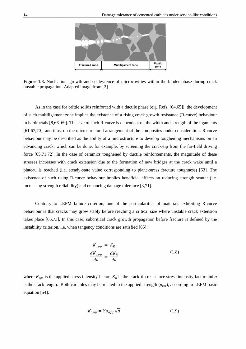
finally the ligament fractures by void growth and coalescence (Figure 1.8) [1,2,57,58,62,63]. Fracture
close to the carbide-binder interface proceeds in a similar manner to that in the binder, i.e. by nucleation,
growth and coalescence of microcavities. However, in this case shallow and closely spaced microvoids
are evidenced running parallel to the binder/carbide interface but within the metallic phase. Fischmeister
et al. [62] attributed the formation of such finer dimple structure to the fulfilment of high triaxiality
conditions in these regions.
14 Damage tolerance of cemented carbides under service-like conditions
Figure 1.8. Nucleation, growth and coalescence of microcavities within the binder phase during crack unstable propagation. Adapted image from [2].
As in the case for brittle solids reinforced with a ductile phase (e.g. Refs. [64,65]), the development
of such multiligament zone implies the existence of a rising crack growth resistance (R-curve) behaviour
in hardmetals [8,66–69]. The size of such R-curve is dependent on the width and strength of the ligaments
[61,67,70]; and thus, on the microstructural arrangement of the composites under consideration. R-curve
behaviour may be described as the ability of a microstructure to develop toughening mechanisms on an
advancing crack, which can be done, for example, by screening the crack-tip from the far-field driving
force [65,71,72]. In the case of ceramics toughened by ductile reinforcements, the magnitude of these
stresses increases with crack extension due to the formation of new bridges at the crack wake until a
plateau is reached (i.e. steady-state value corresponding to plane-stress fracture toughness) [63]. The
existence of such rising R-curve behaviour implies beneficial effects on reducing strength scatter (i.e.
increasing strength reliability) and enhancing damage tolerance [3,71].
Contrary to LEFM failure criterion, one of the particularities of materials exhibiting R-curve
behaviour is that cracks may grow stably before reaching a critical size where unstable crack extension
takes place [65,73]. In this case, subcritical crack growth propagation before fracture is defined by the
instability criterion, i.e. when tangency conditions are satisfied [65]:
𝐾𝐾𝑎𝑎𝑎𝑎𝑎𝑎 = 𝐾𝐾𝑅𝑅
𝑑𝑑𝐾𝐾𝑎𝑎𝑎𝑎𝑎𝑎𝑑𝑑𝑎𝑎
= 𝑑𝑑𝐾𝐾𝑅𝑅𝑑𝑑𝑎𝑎
(1.8)
where Kapp is the applied stress intensity factor, KR is the crack-tip resistance stress intensity factor and a
is the crack length. Both variables may be related to the applied strength (σapp), according to LEFM basic
equation [54]:
𝐾𝐾𝑎𝑎𝑎𝑎𝑎𝑎 = 𝑌𝑌𝜎𝜎𝑎𝑎𝑎𝑎𝑎𝑎√𝑎𝑎 (1.9)
Fractured zone PlasticzoneMultiligament zone
Damage tolerance of cemented carbides under service-like conditions 15
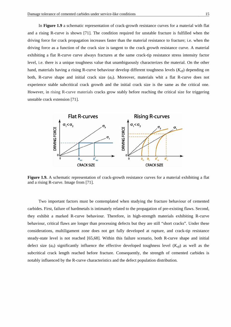
In Figure 1.9 a schematic representation of crack-growth resistance curves for a material with flat
and a rising R-curve is shown [71]. The condition required for unstable fracture is fulfilled when the
driving force for crack propagation increases faster than the material resistance to fracture; i.e. when the
driving force as a function of the crack size is tangent to the crack growth resistance curve. A material
exhibiting a flat R-curve curve always fractures at the same crack-tip resistance stress intensity factor
level, i.e. there is a unique toughness value that unambiguously characterizes the material. On the other
hand, materials having a rising R-curve behaviour develop different toughness levels (Keff) depending on
both, R-curve shape and initial crack size (a0). Moreover, materials whit a flat R-curve does not
experience stable subcritical crack growth and the initial crack size is the same as the critical one.
However, in rising R-curve materials cracks grow stably before reaching the critical size for triggering
unstable crack extension [71].
Figure 1.9. A schematic representation of crack-growth resistance curves for a material exhibiting a flat and a rising R-curve. Image from [71].
Two important factors must be contemplated when studying the fracture behaviour of cemented
carbides. First, failure of hardmetals is intimately related to the propagation of pre-existing flaws. Second,
they exhibit a marked R-curve behaviour. Therefore, in high-strength materials exhibiting R-curve
behaviour, critical flaws are longer than processing defects but they are still “short cracks”. Under these
considerations, multiligament zone does not get fully developed at rupture, and crack-tip resistance
steady-state level is not reached [65,68]. Within this failure scenario, both R-curve shape and initial
defect size (a0) significantly influence the effective developed toughness level (Keff) as well as the
subcritical crack length reached before fracture. Consequently, the strength of cemented carbides is
notably influenced by the R-curve characteristics and the defect population distribution.

16 Damage tolerance of cemented carbides under service-like conditions 1.2.2. Fracture behaviour within the framework of Weibull statistics theory
As previously commented, fracture behaviour of cemented carbides is of stochastic nature as it
originates from the propagation of pre-existing defects [15,45,46,74–76]. Therefore, the strength of
cemented carbides depends on the size, position, orientation and nature of the major flaw and exhibit
wide scatters, due to the variability associated with defects size probability distribution. Consequently,
strength is size-dependent as the probability of finding a major flaw increases when rising specimen size.
Therefore, probabilistic failure mechanics are essential for proper design with this brittle-like material
[73,77]. Within this context, Weibull statistics are claimed as the suitable approach to rationalize not only
the rupture strength of hardmetals, but also their strength scatter. The latter is a parameter of enormous
importance when designing with brittle materials [78].
This statistical approach is based on the theory of the weakest link, which establishes that the
component or sample breaks when the weakest element fails. The application of Weibull statistics to
rupture strength of materials describes the probability of failure (Pf) of specimens of a given volume, V,
subjected to a homogeneous applied tensile stress state, σapp, to cause fracture according to the expression
[79]:
𝑃𝑃𝑓𝑓(𝜎𝜎,𝑉𝑉) = 1 − 𝑒𝑒𝑒𝑒𝑒𝑒 �𝑉𝑉𝑉𝑉0�𝜎𝜎𝑎𝑎𝑎𝑎𝑎𝑎𝜎𝜎0
�𝑚𝑚� (1.10)
where V0 is a normalising volume, and m and σ0 are the Weibull modulus and characteristic strength,
respectively. The former describes the strength scatter (i.e. m rises when decreasing the strength scatter),
and the latter represents the stress state required for having a 63.3% probability of failure.
According to Weibull distribution standards [80], the range of failure probabilities covered by the
experimental assessment of the Weibull curve increases with the dimension of the sample (i.e. the number
of tested specimens). However, due to high specimen’s costs, the number of specimens is usually limited
and careful attention must be paid when extrapolating strength values to really low probabilities of failure
and/or to different effective loaded volumes [81].
1.3. Fatigue behaviour of cemented carbides
The great majority of hardmetals applications are subjected to cyclic and repetitive loads; and
consequently fatigue represents, together with wear and corrosion, one of the principal failure
mechanisms. In addition, similar to the case of brittle fracture, fatigue failures are generally premature

Damage tolerance of cemented carbides under service-like conditions 17
and unexpected. Therefore, they often require of an overall stop of the engineering system, bringing high
additional costs [82]. Hence, the resistance against fatigue becomes a critical design parameter in the
majority of cemented carbides applications. From the above information it is clear that an accurate
description and understanding of the fatigue behaviour of hardmetals is required if the performance of
engineering parts made of these materials are to be optimized. However, literature devoted to study the
influence of the microstructure on the fatigue behaviour of cemented carbides is rather scarce and almost
limited to the straight WC–Co system [82].
1.3.1. Strength degradation under the application of cyclic loads
Fatigue can be defined as a progressive and localized damage that occurs when a material is
subjected to cyclic loading. It involves initiation and evolution of cracks at loads that are too low to cause
failure under monotonic loading. The most common method for evaluating the fatigue behaviour of
structural materials is the applied stress–fatigue life approach (S–N curve), also known as the Whöler plot.
This curve consists on a graph where the cyclic stress (S) is plotted against the number of cycles to failure
(N), the latter in a logarithmic scale. This test methodology includes an interesting parameter, the
endurance limit, which refers to the maximum stress level for specimen survival under a given number of
cycles. Moreover, if for a given cycling stress state the material has an “infinite fatigue life”, usually in
the range between 106 to 108 cycles, the endurance limit can be also referred to as the fatigue limit (σf)
[82,83].
The susceptibility of cemented carbides to be degraded under the application of cyclic loads is a
fact known since 1941 [84]. However, the vast majority of published investigations devoted to study the
fatigue behaviour of hardmetals are concentrated from the 80s until now [82]. From them, it is
noteworthy the systematic and extensive investigation reported by Sockel’s group following the S–N
testing approach (e.g. Figure 1.10a) and complemented with a comprehensive study of fatigue
micromechanisms based on Scanning Electron Microscopy (SEM) and Transmission Electron
Microscopy (TEM) [5,85–91].
Hardmetals are extremely susceptible to the application of cyclic loads, and fatigue limit values up
to 30-40% of the corresponding bending strength have been reported [5,85,86,90,91]. This fatigue
susceptibility is mainly associated with the degradation of the metallic phase [5–7,85,86,89–91].
Therefore, a relevant influence of the microstructure on the susceptibility of cemented carbides to strength
degradation (i.e. fatigue sensitivity) is to be expected. In fact, binder content and composition are the
main parameters influencing fatigue response, even though the carbide mean grain size also plays a
significant role [86,90,91]. Sockel’s group investigated such fatigue susceptibility on the basis of the

18 Damage tolerance of cemented carbides under service-like conditions Whöler plots slope, which is merely indicative of the ratio between the monotonic strength and the fatigue
limit [5,85,86,90,91]. In such a way, they were able to determine an increase of fatigue sensitivity with
binder mean free path, as shown in Figure 1.10b [85]. They also discerned a significant influence of the
binder chemical nature on fatigue sensitivity, concluding that plain Co binder has a higher susceptibility
to be degraded under cyclic loads than NiCo, FeCoNi and FeNi binders [90,91]. As already pointed out
by Krawitz and co-workers [7], Co binder fatigue degradation was rationalized on the basis of the
accumulation of a fatigue-induced fcc to hcp phase transformation [5,90,91]. This deformation
micromechanism restricts significantly the ductility of the metallic binder, recognized as the main
toughening phase in cemented carbides [1,2,58,92]. However, the prevalence of this deformation
mechanism diminishes and/or disappears when replacing cobalt by alternative binders, such as Ni and Fe
[6,7,90,91].
Figure 1.10. (a) S–N curves for a representative hardmetal and cermet grades, and (b) correlation of the slope of the S–N plots, as a measurement of fatigue sensitivity, with the mean free path of binder [85]. Images from [82].
1.3.2. Fatigue crack growth behaviour
The above described S–N approach is the classic and most widely used method to study the fatigue
behaviour of structural materials. However fracture mechanics theory also offers an extensively accepted
framework to evaluate the fatigue response of materials. This approach is based on assessing the number
of loading cycles required to propagate the largest pre-existing flaw to failure [82]. Thus, it describes the
fatigue crack growth (FCG) rates as a function of the range (∆K) and/or the maximum (Kmax) stress
intensity factor. Although the S–N approach is simpler than the fracture mechanics one, the latter offers
three obvious benefits over the former: (1) it is invariably more conservative, as this theory is defect
tolerant and considers that the structures are inherently flawed; (2) it enables a quantitative evaluation of
the damaging effect of flaws or defects within the material; and (3) it provides a rational basis for quality
control of the product [82,83,93]. Thus, on the basis of the well-established assumption indicating that
(a) (b)

Damage tolerance of cemented carbides under service-like conditions 19
subcritical crack growth of pre-existing defects is the controlling stage for fatigue failure in cemented
carbides [5,85,86], the description of the FCG rates as a function of ∆K and/or Kmax appears as a suitable
methodology for evaluating the fatigue behaviour of these materials.
Nowadays it is fully accepted that the FCG behaviour of cemented carbides obeys a Paris-Erdogan
equation:
𝑑𝑑𝑎𝑎𝑑𝑑𝑁𝑁
= 𝐶𝐶∆𝐾𝐾𝑚𝑚′ (1.11)
where da/dN is the crack growth per cycle and C and m’ are microstructurally dependent constants.
However, contrary to the case of metals alloys having m’ values lying between 2 and 4 [94], cemented
carbides exhibit FCG rates with an extremely large powder-dependence on ∆K, as indicated by the high
m’ values within the 10 to 20 range [4,8,95–98].
Similar to the extensive investigation on hardmetals fatigue behaviour carried out by Sockel’s
group following the S–N approach, a large research program was conducted by Llanes group with the
purpose of acquiring a deep knowledge on FCG mechanics and mechanisms of cemented carbides
[4,8,97–99]. Within this context, special effort was devoted to evaluate the influence of the microstructure
on the relative dominance between the static and cyclic failure modes as well as on the fatigue sensitivity
of cemented carbides, this parameter being defined for pre-cracked specimens as the ratio between the
FCG threshold (Kth) and fracture toughness [82].
Research program conducted by Llanes’s group elucidated several aspects on the fatigue behaviour
of cemented carbides, the main being summarized hereafter. First, as already postulated by Fry and Garret
[96], a predominance of static over dynamic failure modes was evidenced, i.e. FCG rates were found to
exhibit a higher dependence on Kmax than on ΔK [4,97]. Furthermore, a modified Paris-Erdogan equation
of type da/dN= CKmaxpΔKq was proposed for assessing the relative dominance of Kmax over ΔK on the
basis of the p/q ratio. In doing so, a decreasing prevalence of static over dynamic failure modes was
discerned when increasing the binder mean free path (Figure 1.11) [4,82,97]. Second, a strong
microstructural influence on fatigue sensitivity of hardmetals, depending on the compromising role
played by the metallic binder as both toughening and fatigue susceptible agent, was evidenced (Figure
1.11) [4]. Third, Torres et al. proposed and validated the fatigue crack growth threshold as the effective
toughness under cyclic loading [97,98]. This was done on the basis of: (1) considering subcritical crack
growth of pre-existing flaws as the controlling stage for fatigue failure; and (2) assuming that fracture
behaviour of hardmetals can be successfully rationalized within fracture mechanics framework.

20 Damage tolerance of cemented carbides under service-like conditions Therefore, this methodology allowed correlating FCG and fatigue limits approaches, within an infinite
life framework. Fourth, in accordance with previous published data [96], mean stress effects (i.e.
associated with the applied load ratio, r = Kmin/Kmax) on the fatigue limit were discerned [97]. Hence,
mean stress effects may be described according to a Goodman-like curve whose slope corresponds to the
fatigue sensitivity under zero mean stress conditions (i.e. r = -1) [97].
1
Figure 1.11. Fatigue sensitivity and p/q ratio evolution as a function of the binder mean free path for WC–Co cemented carbides [4]. Image from [82].
1.4. Service-like damage in cemented carbides
Hardmetals are found at the forefront of a wide range of engineering products that operate under
harsh working conditions. Indeed, cemented carbides are the preferential choice in almost all the
applications where the best solution to wear, impact, corrosion and thermal shock is sought [12].
However, despite their outstanding combination of properties, hardmetals suffer from different in-service
degradation phenomena that seriously affect the performance and service-life of engineering structural
parts. Among them, corrosion and thermal shock are two of the principals and are found in a large
number of applications. The former is found in applications exposed to chemically aggressive media,
including a wide variety of corrosive environments, such as lubricants, chemical and petrochemical
products, and mine and sea waters, among others (e.g. Ref. [48,100–102]). Thus, areas of application
where corrosion resistance is one of the main criteria for the choice of a suitable grade include: wear
parts, particularly in the oil industry and for submarine applications; tools and die industry; and wood-
machining parts, to name a few [12]. Thermal shock, although receiving less attention than corrosion, is

Damage tolerance of cemented carbides under service-like conditions 21
also encountered in several applications. Hence, thermal cracking and thermal fatigue [12,13,82,103,104]
are recognized as common modes of failure of cemented carbide tools in different applications, such as:
intermittent cutting [104,105], rock drilling [100] and some wear parts [12].
1.4.1. Corrosion behaviour
In acidic and neutral pH solutions, hardmetal corrosion process consists on a galvanic couple where
the binder is selectively attacked due to its anodic role [106–108], whereas WC particles are cathodically
protected [108,109] (Figure 1.12). In addition, due to the larger surface area covered by ceramic
particles, corrosion in anodic sites gets enhanced [108]. The opposite trend is found in basic solutions,
where ceramic particles dissolve and the binder phase passivates [110,111]. Corrosion mechanisms in
cemented carbides are really complex and depend on a large number of factors such as surface state,
corrosive media, hardmetal microstructure and binder chemical nature. Furthermore, corrosion system is
in constant evolution due to the continuous changes produced by the cathodic and anodic reactions taking
place at the surface [108].
Figure 1.12. Schematic presentation of the reactions taking place on the WC–Co surface. Image from [108].
Since the metallic binder is the most susceptible phase to corrosion in acidic and neutral media,
major efforts for improving the corrosion resistance of hardmetals have been focused on mitigating the
dissolution of the binder phase. Within this context, the total or partial substitution of cobalt binder by
alternative alloys, which have inherently a higher corrosion-resistance, significantly improves the
corrosion performance of hardmetals in a large variety of neutral and acidic environments
[12,106,107,112–114]. Furthermore, alloying the metal binder with small additions of Cr, up to the

22 Damage tolerance of cemented carbides under service-like conditions solubility limit of the binder, dramatically decreases corrosion rates [12,107,109,112,114–116]. In fact,
Cr3C2 is frequently added in cemented carbides with grain-refining purposes [13,117–119]. During
sintering, main part of the chromium dissolves into the binder and that results in a beneficial effect
against corrosion due to the formation of a passivating Cr2O3 film at the binder surface [109,111,116].
Similar to chromium carbide, Mo2C is added for inhibiting grain growth and improving the wettability
between the binder-WC couple [120], but also rises corrosion resistance due to the formation of a
MoO3 layer that enhances pitting corrosion resistance [121].
The potential of the system plays a critical role in defining corrosion mechanisms of cemented
carbides. In acidic and neutral solutions, at low potentials the binder phase dissolves while the WC grains
remain catholically protected [108,122]. Anodic polarization curve exhibits a pseudopassive region at
intermediate potentials, due to the formation of a non-adhered layer at the surface consisting of corrosion
products that difficult the diffusion of cobalt ion [113,123]. In the third region, corresponding to high
applied potentials, the WC phase is oxidized [106–109,113,123] and a surface WO3 layer is formed
[113,123]. Further, during the anodic polarization, Co dissolves and forms an inner CoO layer and a
Co3-xO4 outer layer, whose composition depends on the pH and passivation potential [113]. An example
consisting of two polarization curves measured for two different WC–Co cemented carbides is shown in
Figure 1.13 [122].
Figure 1.13. Examples of full polarization scans measured for WC–6Co%wt. (square) and WC–16.5Co%wt. (circles) cemented carbides. Image from [122].
In-service performance of cemented carbides is not only dependent on their intrinsic mechanical
properties but also is highly influenced by their resistance to the aggressive medium to which are
exposed. Within this context, corrosion attack exposes WC grains, resulting in a noticeable increase of
wear rates. Accordingly, several studies have been focused on studying the synergic effects between

Damage tolerance of cemented carbides under service-like conditions 23
erosion/abrasion and corrosion on the wear rates of cemented carbides (e.g. Ref. [110,124–126]).
Furthermore, corrosion damage may also induce a detrimental effect on the fracture strength and fatigue
resistance of hardmetals, promoting a premature and un-expected failure [48,82,102,127]. However, to
the best knowledge of the authors, only two studies have been addressed to correlate strength reduction
and corrosion damage in cemented carbides. Both of them pointed out relevant strength degradation due
to the stress raising effects produced by localized corrosion damage in the form of pits [48,102]. Thus,
from a structural integrity perspective, it is essential to understand the detrimental impact that corrosion
damage may induce in the performance of cemented carbides components.
1.4.2. Thermal shock resistance
Despite the exceptional thermal conductivity and excellent fracture toughness of hardmetals in
comparison with ceramic materials, WC–Co cemented carbides are sensitive to thermal shock due to its
brittle-like nature behaviour [128,129]. Thus, sudden temperature changes may result in the apparition of
subcritical microcracks or even in the catastrophic failure of the structural component. However, studies
devoted to investigate the thermal shock resistance of hardmetals are relatively scarce [128–134], and
only a few of them correlate induced damage by thermal shock with resulting remnant properties
[128,130].
The measurement of the retained strength after a quench test is the most widely used method for
evaluating thermal shock resistance of ceramics. The test consists in determining the critical thermal
shock temperature differential (ΔTc) above which the residual strength is reduced up to values of 70% the
average strength measured at room temperature [135]. Within this context, when the microstructure plays
a critical role in defining thermal shock resistance, Hasselman theory is frequently invoked to rationalize
thermal shock behaviour. This theory consists of several parameters (i.e. R parameters) defining the
resistance of the material to either crack initiation or propagation due to thermal shock [136–139]. First
Hasselman thermal shock parameter (i.e. the R parameter) was described by Kingery [137] in the middle
50’s. However, it was not until a few years afterwards that Hasselman introduced the R’’’’ parameter
[138], and later on he proposed the unified thermal shock theory [139]. First Hasselman parameter is
defined as follows:
𝑅𝑅 =𝜎𝜎𝑒𝑒(1 − 𝜈𝜈)𝐸𝐸𝛼𝛼𝑊𝑊𝐶𝐶𝐶𝐶
(1.12)

24 Damage tolerance of cemented carbides under service-like conditions where ν is the Poisson ratio, E is the elastic modulus and αCTE is the coefficient of thermal expansion.
However, in the case of a poor surface heat transfer, the heat conductivity (λ) must be also considered. It
is reflected in the second Hasselman parameter (R’)
𝑅𝑅′ =𝜆𝜆𝜎𝜎𝑒𝑒(1 − 𝜈𝜈)𝐸𝐸𝛼𝛼𝑊𝑊𝐶𝐶𝐶𝐶
(1.13)
On the other hand, the R’’’’ parameter describes the condition necessary for the propagation of
thermal shock induced cracks, and is given by:
𝑅𝑅′′′′ =1
2(1 − 𝜈𝜈) �𝐾𝐾𝐼𝐼𝑐𝑐𝜎𝜎𝑒𝑒�2
(1.14)
Within this framework, Mai successfully rationalized thermal shock behaviour of cemented
carbides according to resistance parameters extracted from Hasselman’s theory for two tool carbides
[128]. In doing so, he suggested that the resistance to degradation of carbide tools under thermal shock
can be described and correlated according to two different parameters: λσr/Eα for crack initiation and
(KIc/σf)2 for crack propagation.
In addition to material properties and the critical temperature difference, there are several factors
that have a relevant influence on the performance of a body subjected to thermal shock. Buessem
proposed a classification of these factors in three groups defining different issues [136]: (1) thermal shock
conditions; (2) geometry of the solid body; and (3) material properties. The first group includes
temperature difference and heat transfer coefficient. The second one considers size and shape of the body.
Finally, the third group accounts for coefficient of thermal expansion, elastic properties, fracture strength
and fracture toughness [136,137]. The shape of the body is an extremely important aspect in determining
the critical temperature difference. In general, it is recommended to avoid corners and edges, since they
can act as thermal stress concentrators [137]. Hence, the critical temperature difference to crack a
specimen can be defined as the crack initiation resistance parameter, either R or R’, multiplied by a shape
factor (S’) (i.e. ΔTc = R·S’ or ΔTc = R’·S’) [137].
From a physical viewpoint, thermal shock damage in cemented carbides principally proceeds
through the nucleation of microcracks at the carbide/binder interface which tend to propagate avoiding
the hard phase [131,132,134]. This is due to the large difference between coefficients of thermal
expansion of WC and Co phases as well as to the high elastic modulus of the composite material. Thus,
severe temperature changes generate significant large thermal stresses that may induce the formation of

Damage tolerance of cemented carbides under service-like conditions 25
microcracks at the carbide/binder interface [131,132]. Maximum cooling tensile stresses are concentrated
at the surface [133,140], and the magnitude of these induced stresses is a direct function of: coefficient of
thermal expansion, elastic modulus and temperature difference [133].
1.5. Focused Ion Beam system
The commercial use of FIB systems started about 30 years ago for their use in the microelectronics
industry, but it was not until the early 90s that become popular in a broader range of Material Science
topics [141]. When equipped with an additional SEM column, it can be used for a large number of
applications including TEM foils preparation, micromachining of specimens, cross-section milling, atom
probe post preparation, and 3D FIB/FESEM tomography [141].
The operation principle of the FIB microscope consists of sputtering atoms onto a target material,
with a high energetic gallium ion beam. The ions are generated from a Ga liquid metal ion source
composed of a Ga reservoir mounted above of a tungsten needle. Ga source is heated up to its melting
point and then it flows to the tip of the needle. An intense electric field is produced at the source tip that
ionizes the gallium, draws the liquid metal into the fine tip, of about 2-5 nm in diameter, and extract ions
from that narrow tip. The Ga ions are accelerated down the column in an electrical field of about 30 KeV
and sputtered over the region of interest [141,142]. Initial FIB systems were equipped with a single beam
that was used for both imaging and preparing microstructural cross-sections. However, this system had
several limitations and nowadays a great number of FIB systems are equipped with an additional SEM
column, which allows an improved flexibility by using the FIB column preferentially to cross-section and
the SEM one to image [141].
1.5.1. 3D FIB/FESEM Tomography
Tomography is a method to obtain a three-dimensional (3D) image of the internal structures of a
solid object through the reconstruction of ‘slices’ (i.e. a tomographic image) of sequential cross sections.
This technique is used in a large number of sciences, such as medicine, biology and archaeology, besides
materials science. In recent years, this technique has received an increasing interest for the
characterization of materials, as it allows acquiring and analysing a large amount of microstructural data
that cannot be gathered using 2D imaging. Specifically, 3D tomography is really useful for studying
spatial distribution of phases, real feature shapes and sizes and feature connectivity [141]. Furthermore,
generated data can be exported to finite element analysis software’s to simulate real microstructures.

26 Damage tolerance of cemented carbides under service-like conditions
There exist several methods to generate 3D visualization currently used in material science, such as
serial sectioning, X-ray tomography, TEM-based tomography and atom probe tomography [141]. The
selection of the proper method depends on the desired spatial resolution and on the sample length scale
[143]. The tomographic technique of interest for this thesis consists of the combined use of focused ion
beam and field emission scanning electron microscopy techniques for reconstructing 3D volumes (i.e.
FIB/FESEM tomography).
FIB-based tomography is the appropriate technique to reconstruct volumes of several microns per
slide with submicron resolution. It has the advantage of requiring little sample preparation and a wide
range of materials can be employed. Generally the first step is to deposit a metal layer over the surface of
interest, normally platinum-based or tungsten-based, to protect it from damage during subsequent milling
and imaging, and also to minimize ‘curtaining’ effects. The next step consists of sputtering a trench
normal to the surface of the sample adjacent to the area of interest. Once the cross-section is prepared,
thin serial sections can be sputtered by FIB and subsequently imaged with the SEM. The process is
repeated several times until the volume of interest has been milled and imaged. General stack of images
contains between 100 and 300 micrographs that are finally aligned and treated for the 3D reconstruction.
This process is generally performed using a commercial software package, and can be tedious depending
on the time required to process and correct the images [141,142]. Once the 3D volume is reconstructed,
software packages allow visualizing particular cross-sections in different orientations and to obtain and
analyse a large amount of data on the reconstructed bulk [141].

Damage tolerance of cemented carbides under service-like conditions 27
Chapter 2
Aims and scope of the work
As previously commented, the industry of cemented carbides is immersed in a highly dynamic and
competitive marked, continuously seeking for more efficient products. In addition, there is a major
interest in replacing W and Co because they are classified as critical materials for the “industrial world”,
as well as due to the healthy issues related to Co powder [17]. Given this situation, a higher degree of
expertise is demanded for the development and suitable design of new hardmetal products with improved
performance, increased reliability and longer working-life. Thus, it is indispensable to acquire a deep
understanding of service degradation phenomena in cemented carbides in order to discern the key
microstructural aspects to consider for improving their behaviour. Within this context, the main target of
this Ph.D. thesis is to improve the performance and enhance the reliability of cemented carbides
tools and components in rupture-limited applications, on the basis of improved damage tolerance
and reduced fatigue sensitivity through an optimal microstructural design.
Following the above ideas, and taking into account that rupture-limited applications include cases
associated with variable combinations of stress state and operating environments, the objectives of this
thesis include the evaluation, analysis and understanding of microstructural effects on the fracture and
fatigue behaviour of cemented carbides, as well as the assessment of the evolution of microstructure-
property-performance interrelations of these materials when damage is induced during service, either by
localised corrosion or thermal shock.
2.1. Fracture behaviour of cemented carbides
A higher relevance of fracture toughness is required in order to increase damage tolerance and
reliability of cemented carbides. Main goal behind that is to diminish the sensitivity of these materials to
critical flaw size [3]. Main toughening mechanism in hardmetals derives from plastic stretching of crack-

28 Damage tolerance of cemented carbides under service-like conditions bridging ductile enclaves at the crack wake [1,2,59,61]. Hence, hardmetals exhibit a rising crack growth
resistance (R-curve) behaviour related to the development of an effective multiligament zone [67,68]. In
this regard, damage tolerance capability is intimately related to development of such R-curve behaviour,
which is dependent upon the width and strength of the metallic bridges; and therefore, on the
microstructural characteristics. Within this framework, the first objective of this Ph.D. thesis is to
document and analyse the toughening phenomenon in cemented carbides as the main foundation
for understanding their fracture mechanisms, with the purpose of proposing a model for the
description of their R-curve behaviour. As mentioned above, R-curve characteristics, which are
strongly influenced by the microstructure, greatly impact the strength and reliability of hardmetals.
Accordingly, the second objective is to assess microstructural effects on the R-curve behaviour of
hardmetals and to evaluate the implications of the crack-bridging toughening mechanism on the
strength and reliability of these materials. Both, the constrained binder and the WC/Co interface, play
a major role in defining effective toughening in cemented carbides. Within this context, it is also the
purpose of this thesis to assess the deformation mechanisms and failure strength of the constrained
ligaments and their interface through compression of micropillars consisting of Co-binder
ligaments constrained by their surrounding WC carbides.
2.2. Fatigue mechanics and mechanisms of cemented carbides
Although fatigue is recognized to play an active and relevant role as a service degradation
mechanism in most of cemented carbides applications, literature surveys devoted to investigate the
influence of the microstructure on the fatigue behaviour are relatively scarce and mainly focused to Co-
base cemented carbides [82]. Fatigue damage is principally associated with mechanisms occurring in the
metallic binder phase and mainly consists of preventing the formation of ductile enclaves at the crack
wake [4]. Thus, opposite to fracture toughness, fatigue threshold values are rather independent on the
binder content and therefore, straight WC–Co grades exhibit increasing fatigue sensitive as binder content
rises [4,91]. Fatigue damage accumulation in the cobalt binder is speculated on the basis of a martensitic
transformation from the fcc to the hcp phase as a consequence of high induced stresses and strains [5].
However, fatigue-induced damage mechanisms shift from the fcc to hcp phase transformation to slip and
twinning when modifying the binder chemical nature from cobalt to nickel; raising then queries on the
effective fatigue susceptibility of binders with distinct chemical nature [6,7]. Therefore, based on the
above comments and on the manifest interest of replacing cobalt by alternative binders [17], it is one of
the objectives of this thesis to investigate and understand the fatigue mechanics and mechanisms of
cemented carbides consisting of binders with non-transforming deformation mechanisms.
On the other hand, crack-deflection is an additional operative toughening mechanism in cemented
carbides. However, opposite to crack-bridging toughening mechanism, it is immune to fatigue loads [8].

Damage tolerance of cemented carbides under service-like conditions 29
Therefore, lower fatigue sensitive levels are expected for hardmetals exhibiting high crack-deflection
toughness enhancement. In this sense, coarse microstructures are envisaged to possess a more effective
action of this toughening mechanism. Within the above framework, it is also the purpose of this doctoral
thesis to evaluate the influence of the carbide mean grain size on the crack-deflection toughening
mechanism in cemented carbides.
2.3. Damage tolerance of cemented carbides under service-like conditions: corrosion and thermal shock
A large portion of hardmetal research is devoted to evaluate and analyse microstructure-property
relations. However, although it is a valid approach, it is strongly convenient for hardmetal industry to
move one step further towards the evaluation of how these microstructure-property relations evolve
through the service-life of hardmetal tools and components. In this regard, a change of perspective in the
direction of understanding the microstructure-property-performance interrelations in cemented carbides
would certainly enable major advances. In this sense, a successful approach was presented by Góez et al.
[50] on the basis of the assessment of the residual strength of hardmetals after the inducement of
controlled damage by means of spherical indentation (i.e. Hertzian contact). Following these ideas, this
thesis aims to investigate the relevance of the microstructure in the tolerance of cemented carbides to
damage induced by localised corrosion or thermal shock. These two service degradation phenomena are
found in a large number of cemented carbide applications [12]. Thus, a final goal of this thesis is to
conduct a systematic study on the influence of the microstructure on the tolerance of cemented
carbides to damage-related features induced either by localised corrosion or thermal shock. In both
cases, toughness and R-curve characteristics are assumed to be dominant properties for enhanced
performance and reliability.

30 Damage tolerance of cemented carbides under service-like conditions

Damage tolerance of cemented carbides under service-like conditions 31
Chapter 3
Experimental details
The experimental details of each part of this thesis are presented in the respective articles.
Nonetheless, some additional details are provided in this chapter for easier follow-up. Concretely, the
nomenclature and the experimental process followed to measure the microstructural parameters and the
“basic” mechanical properties of all cemented carbide grades studied and presented in the thesis are
summarized below. Furthermore, experimental details on the 3D FIB/FESEM reconstruction process are
also given.
3.1. Materials: nomenclature and microstructural characterization
In this Ph.D. thesis a total of 14 different hardmetal grades are investigated. All materials are
experimental grades supplied by Sandvik Hyperion. In order to select a criterion enabling a fast and easy
recognition of the microstructural characteristics, a nomenclature consisting of three different indexes is
proposed. The first index is composed by one or two digits that represent the binder weight content. The
second one refers to the chemical nature of the binder (i.e. Co, Ni or CoNi). Finally, the third index is
associated with the mean grain size of the carbide phase: UF for ultrafine, F for fine, M for medium and C
for coarse. Please note that in some articles if the grade is composed by plain Co, the second index is not
explicitly indicated.
The main microstructural parameters used in this investigation include: binder weight content
(Vwtbinder), binder composition, carbide mean grain size (dWC), carbide contiguity (CWC) and binder mean
free path (λbinder). Binder content values refer to the nominal composition, as given by the supplier.
Carbide mean grain size is measured following the linear intercept method in FESEM micrographs
acquired using a Jeol JSM-7001F unit [144]. Prior to the acquisition of the micrographs, samples were
mounted in Bakelite, then ground and diamond polished up to mirror-like surface finish following a 6, 3
and 1 μm sequence, with a final colloidal silica stage. The magnification of the micrographs was selected

32 Damage tolerance of cemented carbides under service-like conditions so that they contained around twenty carbides in the horizontal direction. Furthermore, in order to reduce
grain size uncertainty, at least 400 grains were measured for each investigated hardmetal grade. On the
other hand, two-phase parameters, CWC and λbinder, were estimated from best-fit empirical equations given
in literature [10,42,145]. Nomenclature and key microstructural parameters for the hardmetal grades
studied in this Ph.D. thesis are given in Table 3.1.
Specimen code
Binder Composition
Additives Vwt
binder
(%wt.)
dWC (µm)
CWC
λbinder
(µm)
3CoUF Co Cr3C2 3 0.37 ± 0.22 0.74 ± 0.04 0.09 ± 0.05
6CoUF Co Cr3C2 6 0.40 ± 0.21 0.61 ± 0.12 0.12 ± 0.06
10CoUF Co Cr3C2 10 0.39 ± 0.19 0.46 ± 0.06 0.16 ± 0.06
11CoM Co Cr3C2 11 1.12 ± 0.71 0.38 ± 0.07 0.42 ± 0.28
10CoC Co - 10 2.33 ± 1.38 0.31 ± 0.11 0.68 ± 0.48
15CoUF Co Cr3C2 15 0.47 ± 0.22 0.36 ± 0.02 0.24 ± 0.11
15CoM Co - 15 1.15 ± 0.92 0.30 ± 0.07 0.55 ± 0.46
15CoC Co - 15 1.70 ± 1.08 0.27 ± 0.07 0.77 ± 0.54
22CoM Co - 22 1.64 ± 0.75 0.19 ± 0.04 1.13 ± 0.56
9NiF Ni Cr3C2 9 0.83 ± 0.49 0.44 ± 0.08 0.29 ± 0.18
10CoNiM 8%wt.Co - 2%wt.Ni - 10 1.04 ± 0.83 0.41 ± 0.08 0.36 ± 0.29
10CoNiC 8%wt.Co - 2%wt.Ni - 10 1.44 ± 0.86 0.38 ± 0.08 0.47 ± 0.30
15CoNiM 12%wt.Co - 3%wt.Ni - 15 1.26 ± 0.81 0.29 ± 0.06 0.60 ± 0.40
15CoNiC 12%wt.Co - 3%wt.Ni - 15 1.50 ± 1.00 0.28 ± 0.07 0.68 ± 0.49
Table 3.1. Specimen code, binder composition, additives, binder content, carbide mean grain size, carbide contiguity and binder mean free path for the investigated cemented carbides.
3.2. Mechanical characterization
Mechanical characterization includes the assessment of hardness (HV30), flexural strength (σr),
Weibull characteristic strength (σ0) and modulus (m), and fracture toughness (KIc). Hardness was
measured using a Vickers diamond pyramidal indenter and applying a load of 294 N. In all the others
cases, testing was conducted using a four-point bending fully articulated test jig, with inner and outer
spans of 20 and 40 mm, respectively. Flexural strength tests were performed on an Instron 8511
servohydraulic machine at load rates of 100 N/s [146]. Bars of 45 mm x 3 mm x 4 mm (i.e. length x
thickness x width) dimensions were used as tested specimens, and the number of specimens broken varied
between 10 and 15 per grade. The surface subjected to the maximum tensile loads was polished to mirror-
like finish and the edges were chamfered to reduce their effect as stress raisers. Flexural strength results
were analysed using Weibull statistics and the Weibull characteristics strength and modulus assessed

Damage tolerance of cemented carbides under service-like conditions 33
[80]. Fracture toughness was determined using 45 mm x 5 mm x 10 mm single edge pre-cracked beam
(SEPB) specimens following the procedure proposed by Torres et al. [147]. In doing so, a notch was
introduced by electrical discharge machining (EDM) up to a length-to-specimen width ratio of 0.3, and a
sharp crack was generated from the notch tip by subjecting the specimens to cyclic compressive loads.
Then, the crack was propagated by applying tensile cyclic loads until reaching a crack length-to-specimen
width ratio of about 0.5. The sides of SEPB specimens were polished to follow stable crack growth using
a high-resolution laser scanning confocal microscopy. Fracture toughness was determined by testing
SEPB specimens to failure at stress-intensity factor load rates of about 2 MPa·m1/2/s. At least five samples
were tested per studied hardmetal grade [148]. Determined mechanical properties for the investigated
cemented carbides are given in Table 3.2.
Specimen code
HV30 (GPa)
σr (MPa)
σ0 (MPa)
Weibull modulus
KIc (MPa)
3CoUF 18.9 ± 0.8 2214 ± 313 2351 8 7.3 ± 0.7
6CoUF 16.9 ± 0.2 3287 ± 473 3506 7 8.4 ± 0.3
10CoUF 15.7 ± 0.6 3422 ± 512 3598 11 10.4 ± 0.3
11CoM 12.8 ± 0.2 3101 ± 102 3149 36 13.9 ± 0.3
10CoC 11.4 ± 0.2 2489 ± 85 2522 35 15.8 ± 0.3
15CoUF 13.2 ± 0.1 3869 ± 109 3919 42 11.3 ± 0.6
15CoM 11.2 ± 0.1 2912 ± 88 2912 39 15.2 ± 0.4
15CoC 10.2 ± 0.1 2570 ± 54 2570 54 17.0 ± 0.2
22CoM 7.7 ± 0.1 2431 ± 124 2487 24 19.4 ± 1.4
9NiF 13.2 ± 0.2 3080 ± 210 3175 17 11.5 ± 0.2
10CoNiM 12.3 ± 0.1 2720 ± 198 2823 23 14.2 ± 0.4
10CoNiC 11.6 ± 0.1 2534 ± 94 2576 32 15.3 ± 0.3
15CoNiM 10.2 ± 0.1 2634 ± 101 2814 33 15.8 ± 0.4
15CoNiC 9.45 ± 0.1 2716 ± 101 2726 31 17.3 ± 0.4
Table 3.2. Hardness, flexural strength, Weibull characteristic strength, Weibull modulus and fracture toughness values for the investigated cemented carbides.
3.3. 3D FIB/FESEM Tomography
Throughout this thesis several 3D FIB/FESEM tomographic reconstructions of different damage-
related features in cemented carbides are presented. In particular, this technique is implemented to
characterize fracture and fatigue phenomena and corrosion process in hardmetals. Within this context, an
explanation of the followed process is detailed hereafter.

34 Damage tolerance of cemented carbides under service-like conditions
The first step consists of selecting the region of interest with dimensions of about 15 µm x 15 µm
for the tomographic reconstruction. Before ion milling, a platinum thin protective layer was deposited
over the surface of interest to reduce milling damage and to avoid “curtaining” effects. This undesirable
effect is very common when milling materials containing several phases, especially when having pores or
void regions such as cracks. Two mark lines were milled, having an angle of 45º between them and
sharing one contact point at one of the square vertices of the platinum layer, in order to facilitate further
alignment of the micrographs. Subsequently, a U-shaped trench with one cross-sectional surface
(perpendicular to specimen surface) was sputtered by FIB. Normally high currents in the nA range are
used in this step to reduce milling times. Next step consists of the combined use of FIB and FESEM
systems to serial sectioning and imaging the surface of interest. At this stage much lower currents were
operated (i.e. in the range of pA) with the purpose of obtaining well-polished surfaces and to lessen
redeposition. Sections of about 20 nm in width were milled and more than 500 images were recorded per
tomography.
Once micrographs of interest are gathered, next step consists of carrying out the 3D reconstruction
of the volume of interest. Aiming to do so, the commercial software Avizo® was used in this
investigation. First, the images were aligned using the line marks on the top of the micrographs (coming
from the ones milled in the platinum layer). Then, the region of interest was selected and cropped.
Subsequently, a series of image filters were applied to the images, in order to differentiate grey levels
associated with each phase. In some cases, particularly when having curtaining effects, this process was
not straightforward and some manual corrections were required. Finally the 3D volume was
reconstructed.

Damage tolerance of cemented carbides under service-like conditions 35
Chapter 4
Articles presentation
This Ph.D. thesis is divided in three sections covering: (1) fracture and (2) fatigue behaviour of
hardmetals, and (3) tolerance of these materials to damage-related features, induced either by thermal
shock or corrosion. First section consists of four published articles, referred to as Articles I, II, III and
IV. The second chapter is composed of two additional papers, Articles V and VI. Finally, the third part
contains two papers, Articles VII and VIII. An additional contribution to the third section is included in
Annex I. The contribution made by the author of this thesis to these papers is detailed in Table 4.1.
Paper Design and planning
Literature survey Experiments 3D
Reconstruction Data collection
and analysis Writing
I S.R. P.R. P.R. S.R. P.R. P.R.
II P.R. P.R. S.R. N/A P.R. P.R.
III P.R. P.R. P.R. N/A P.R. P.R.
IV P.R. P.R. P.R. N/A P.R. P.R.
V S.R. P.R. P.R. N/A P.R. P.R.
VI P.R. P.R. P.R. N/A P.R. P.R.
VII S.R. P.R. S.R. S.R. P.R. P.R.
VIII P.R. P.R. P.R. N/A P.R. P.R.
Table 4.1. Contribution statement of the author to the appended papers. Note that P.R. refers to “principal role” and S.R. to “secondary role”. N/A= Not applicable.

36 Damage tolerance of cemented carbides under service-like conditions 4.1. Fracture behaviour of cemented carbides
The primary objective of this section is the acquisition of a deep knowledge of the fracture
mechanics and mechanisms in cemented carbides. Main outcome of this study is to discern the critical
role played by the microstructure in defining the fracture strength and reliability of these materials. In
doing so, special attention is devoted to reveal key microstructural features of cemented carbides for
optimizing their fracture behaviour by means of enhanced crack growth resistance (R-curve) behaviour.
This section is composed of four published articles.
Article I carries out a comprehensive study of the toughening and fatigue micromechanisms
operative in WC–Co hardmetals when subjected to monotonic (toughness) and cyclic (fatigue) loading
conditions. Here, crack-microstructure interactions at the crack-tip of stably grown and arrested cracks,
propagated under the application of monotonic and cyclic loads, are analysed by means of 3D
FIB/FESEM serial sectioning and imaging technique. Following the above investigation, main purpose of
Article II is to bring new insights on mechanical deformation and failure behaviour of hardmetals
through the compression of micropillars consisting of Co-binder ligaments constrained by their
surrounding WC carbides. In this study particular focus is placed on documenting and analysing
deformation mechanisms and failure strength of the ductile binder (i.e. yield strength and constraining
degree of the soft phase) and the WC/Co interface, as key features for determining effective toughening in
cemented carbides. On the other hand, in Article III the micrographs gathered in Article I of crack–
microstructure interaction in cracks arrested after stable extension under monotonic loading (i.e.
multiligament zone) are analytically assessed, and a model for the description of R-curve behaviour of
hardmetals is proposed. Finally, Article IV evaluates the influence of microstructure on the R-curve
behaviour of cemented carbides; and in turn, addresses the impact of R-curve characteristics on the
strength and reliability of these materials.
Damage tolerance of cemented carbides under service-like conditions 37
Article I. Fracture and fatigue behavior of cemented carbides: 3D Focused Ion Beam Tomography of crack-microstructure interactions
Reference: J.M. Tarragó, E. Jimenez-Piqué, M. Turón-Viñas, L. Rivero, I. Al-Dawery, L.
Schneider, L. Llanes, Int. J. Powder Metall. 50 (2014) 1–10. “Best paper award in the 2014 World
Tungsten, Refractory & Hardmaterials Conference”
This work provides a significant contribution to the understanding of fracture and fatigue failure
processes in cemented carbides. It includes a 3D characterization of crack-microstructure interaction in
the process zone (i.e. crack-tip) of stably propagated and arrested cracks, under the application of
monotonic and cyclic loads. This investigation stands out the critical role played by the constrained
binder as both the toughening and fatigue susceptible agent. Hence, unequivocal proof of the
multiligament zone as main foundation for understanding toughness and R-curve behaviour in cemented
carbides is provided. In addition, clear evidence of fracture and fatigue mechanisms within the binder
metallic phase are given, and the differences between both failure mechanisms are analysed and
discussed.

38 Damage tolerance of cemented carbides under service-like conditions Article II. Mechanical deformation of WC–Co composite micropillars under uniaxial compression
Reference: J.M. Tarragó, J.J. Roa, E. Jiménez-Piqué, E. Keown, J. Fair, L. Llanes, Int. J. Refract.
Met. Hard Mater. 54 (2016) 70–74.
The effective strength and ductility of the constrained binder together with the interface properties
between carbide and binder are critical features for rationalizing microstructural effects on toughening
and fatigue sensitivity of cemented carbides. Within this context, the compression behaviour of
micropillars consisting of a binder ligament constrained by the surrounding carbides is assessed, with the
purpose of gaining a deeper understanding of such features. In doing so, micropillars are machined using
FIB milling and uniaxially compressed ex-situ using a nanoindenter equipped with a diamond flat punch.
Following the compression tests, deformation and failure micromechanisms are examined by FESEM and
FIB cross-sectioning. Experimental results indicate that boundaries between either carbide and binder or
carbide crystals are preferential sites for irreversible deformation and failure phenomena. Moreover,
plasticity is mostly evidenced within the softer metallic binder in the regions adjacent to carbide-binder
interface, where maximum triaxiality stress conditions prevail. Stress-strain curves are analysed and
several strain bursts are evidenced at different stress levels, revealing different damage mechanisms on
the basis of different crystal orientation and local phase assemblage. Furthermore, this investigation
provides a new insight into the microstructural design of ductile metal reinforced ceramic-base
composites, on the basis of micropillar compression tests as a valid and effective experimental procedure
for the evaluation of mechanical response of these materials at the microscopic level.

Damage tolerance of cemented carbides under service-like conditions 39
Article III. FIB/FESEM experimental and analytical assessment of R-curve behavior of WC–Co cemented carbides
Reference: J.M. Tarragó, E. Jiménez-Piqué, L. Schneider, D. Casellas, Y. Torres, L. Llanes, Mater.
Sci. Eng. A 645 (2015) 142–149.
The principal objectives of this work are to analyse the toughening mechanics and mechanisms of
cemented carbides and to propose a model for the description of their R-curve behaviour. In doing so, the
R-curve behaviour of a WC–11%wt.Co cemented carbide is assessed by critical analysis of the
FIB/FESEM micrographs gathered in Article I, containing evidence of crack-microstructure interaction
at the wake of stably grown cracks under monotonic loading. Experimental results point out that
cemented carbides exhibit a steep but short R-curve behaviour, due to the large stresses supported by the
highly constrained and strongly bonded bridging ligaments. Relevant strength and reliability
enhancements can be attributed to this toughening scenario.

40 Damage tolerance of cemented carbides under service-like conditions Article VI. Microstructural effects on the R-curve behavior of WC–Co cemented carbides
Reference: J.M. Tarragó, D. Coureaux, Y. Torres, D. Casellas, I. Al-Dawery, L. Schneider and L.
Llanes, Microstructural effects on the R-curve behavior of WC–Co cemented carbides, Mater. Des. 97
(2016) 492–501.
This article addresses an investigation on the microstructural effects on the R-curve characteristics
of cemented carbides. Special attention is paid to evaluate the influence of the crack-bridging mechanism
on the strength and reliability of hardmetals. To this end, the model proposed in Article III for R-curve
description is implemented for rationalizing the fracture behaviour of WC–Co cemented carbides with
different microstructural arrangements. Strength and reliability enhancements are discussed on the basis
of the effective developed toughness and the subcritical crack extension reached before unstable growth is
triggered. Both phenomena are considered to be dependent on microstructural length scale and initial flaw
size.

Damage tolerance of cemented carbides under service-like conditions 41
4.2. Fatigue mechanics and mechanisms in cemented carbides
The vast majority of hardmetal tools and components are subjected to repeated loads, and fatigue is
recognized as one of the most common failure mechanism in their industrial application [82]. Due to its
metallic nature, the binder is the principal fatigue susceptible agent in hardmetals and fatigue
phenomenon is mainly based on the inhibition or degradation of the crack-bridging toughening
mechanism. Therefore, fatigue response of hardmetals is highly sensitive to their microstructural
characteristics, especially to the binder content and chemical nature. Within this context, this chapter
covers to main topics: (1) acquisition of a deeper knowledge on the fatigue micromechanisms of
hardmetals (Article I) and, (2) evaluation of the influence of the microstructure, including the binder
chemical nature and carbide mean grain size, on the FCG behaviour and fatigue sensitivity of cemented
carbides (Articles V and VI).
As explained previously, Article I is addressed to investigate the toughening and fatigue
micromechanisms of cemented carbides through the implementation of the 3D FIB/FESEM tomographic
technique. On the other hand, Articles V and VI are focused to study the fatigue mechanics and
mechanisms of hardmetals with Ni-containing binders, and to compare them with respect to WC–Co
hardmetals. Indeed, hardmetal producers are devoting great efforts in replacing Co binder by alternative
binders [17]. Main reasons behind such trend include: (1) health issues related with cobalt powder
[19,20], (2) high and fluctuating prices of Co due to its scarcity related to the difficult access to the ore
mines, and (3) intention of improving the performance of cemented carbides under certain harsh work
conditions such as corrosive environments. Among possible Co substitutes, nickel has received the most
attention as an alternative binder because of its similarity in structure and properties, besides its good
corrosion resistance. Article V includes a detailed study of the fatigue behaviour of a fine grain-sized
WC–Ni cemented carbide, and results are compared to that expected for a WC–Co hardmetal with alike
microstructural parameters. On the other hand, Article VI consists of a systematic study on the influence
of the mean carbide grain size and the binder chemical nature (i.e. Co vs. CoNi) on the FCG behaviour of
cemented carbides.

42 Damage tolerance of cemented carbides under service-like conditions Article V. Mechanics and mechanisms of fatigue in a WC–Ni hardmetal and a comparative study with respect to WC–Co hardmetals
Reference: J.M. Tarragó, C. Ferrari, B. Reig, D. Coureaux, L. Schneider, L. Llanes, Mechanics
and mechanisms of fatigue in a WC–Ni hardmetal and a comparative study with respect to WC–Co
hardmetals, Int. J. Fatigue. 70 (2015) 252–257.
As mentioned in the introduction, fatigue degradation of Co-base cemented carbides has been
frequently rationalized on the basis of a cyclic-induced accumulation phase transformation within the Co
binder [5,90,91]. It raises then queries on the effective fatigue susceptibility of binders with distinct
chemical nature (e.g. Ni-containing ones). Accordingly, in this paper the fatigue behaviour of a WC–Ni
hardmetal consisting of a binder with non-transforming deformation mechanisms (i.e. slip and twinning
[6,7]) is evaluated. In doing so, the FCG behaviour and fatigue life limit (stair-case method) values are
assessed. Fatigue sensitivity is also addressed and found to be similar to that speculated for a Co based
grade with similar microstructural characteristics. Up to the knowledge of the authors, this is the first
paper on the open literature about fatigue strength and fatigue crack growth behaviour of WC–Ni
cemented carbides. This investigation also includes a detailed inspection of fatigue micromechanisms
within the binder, where step-like crystallographic features similar to that evidenced in WC–Co
hardmetals are discerned. Such fatigue failure mode is postulated to be a direct consequence of
comparable size length scales of microstructure and cyclic plastic zone in front of the crack-tip. Hence,
the finding of both similar fatigue fractographic faceted features and fatigue sensitivity for Ni- and Co-
base hardmetals call into question the speculated role played by the fcc to hcp martensitic phase
transformation as a critical fatigue micromechanism in Co-base hardmetals.

Damage tolerance of cemented carbides under service-like conditions 43
Article VI. Fracture and fatigue behavior of WC–Co and WC–CoNi cemented carbides
Reference: J.M. Tarragó, J.J. Roa, V. Valle, J.M. Marshall, L. Llanes, Fracture and fatigue
behavior of WC–Co and WC–CoNi cemented carbides, Int. J. Refract. Met. Hard Mater. 49 (2015) 184–
191.
The main purpose of this work is to evaluate the fatigue behaviour of Ni-containing binder
hardmetals (concretely 74 %wt. Co and 26 %wt. Ni), and to compare such behaviour with the one exhibited
by cemented carbides containing plain Co as a binder. Furthermore, in this paper the influence of the
binder content and the carbide mean grain size on the fatigue response is assessed. Therefore, the
experimental protocol followed in this investigation is broadly equivalent to that pursued in Article V.
Results indicate a negligible influence of the binder chemical nature on the FCG behaviour and fatigue
sensitivity of studied cemented carbides. On the other hand, the FCG threshold is found to linearly
increase when rising carbide mean grain size, due to a more effective action of the crack-deflection
mechanism. Similar faceted fatigue features were evidenced for Co and CoNi binders.

44 Damage tolerance of cemented carbides under service-like conditions 4.3. Structural integrity of cemented carbides subjected to service-like damage:
corrosion and thermal shock
As previously commented, cemented carbides tools and components suffer from several damage-
related features induced during service, such as occasional hard body impacts, contact-related
degradation, thermal shock or corrosion. Such damage, when combined with the high monotonic and
cyclic loads to which engineering parts are generally subjected, limits the service life and may induce
premature and unexpected failures. Generally, in-service real degradation is not merely associated with a
unique type of damage, but rather consists on a synergic action among several types of them. However, in
order to understand the real operational degradation conditions, it is first necessary to isolate individual
elements and to acquire a deep knowledge on the effective action of each one of them. Within this
context, the main purpose of this chapter is to study the corrosion and thermal shock damage related
features in cemented carbides, and to evaluate the critical role played by the microstructure in tolerating
such damage. In doing so, microstructural effects are assessed on the basis of their resistance to damage,
the latter as given by either microcracking induced by thermal shock [134] or pits formed due to localized
corrosive attack [48,102]. With that purpose, damage tolerance is accounted by using residual strength as
a critical "limit state" parameter according to the induced damage level. In both cases, toughness and R-
curve characteristics are assumed to be dominant properties for enhanced performance and reliability.
This chapter consists of two papers, one of them devoted to study corrosion damage in cemented
carbides (Article VII), and a second one committed to the thermal shock behaviour of hardmetals
(Article VIII). An additional contribution to investigate the influence of the microstructure on the
corrosion damage in hardmetals is given in Annex I. Article VII studies the corrosion behaviour of an
ultrafine-sized WC–Co cemented carbide immersed in a synthetic mine water solution. The paper
includes a detailed characterization of corrosion damage by means of the 3D FIB/FESEM technique.
Moreover, the effect of corrosion damage on the structural integrity is assessed through the measurement
of residual strength. Also, a detailed FESEM inspection is conducted to discern critical corrosion pits that
promote failure. In Article VIII the influence of the microstructure on the thermal shock behaviour of
hardmetals is assessed. In doing so, the samples are subjected to single and repetitive sudden temperature
changes, and the induced damage is evaluated by measuring the retained strength. Attained results are
correlated with those estimated from Hasselman parameters for describing crack initiation and
propagation in structural materials when subjected to thermal shock [138,139]. In addition, a detailed
fractographic inspection is carried out to discern possible damage induced by thermal shock.

Damage tolerance of cemented carbides under service-like conditions 45
Article VII. Corrosion damage in WC–Co cemented carbides: residual strength assessment and 3D FIB-FESEM tomography characterisation
Reference: J.M. Tarragó, G. Fargas, E. Jimenez-Piqué, A. Felip, L. Isern, D. Coureaux, J.J. Roa, I.
Al-Dawery, J. Fair, L. Llanes, Corrosion damage in WC–Co cemented carbides: residual strength
assessment and 3D FIB-FESEM tomography characterisation, Powder Metall. 57 (2014) 324–330.
“Keynote paper award in the Euro PM 2014 Congress & Exhibition”
This work investigates the corrosion damage resulting after immersion of a WC–15%wt.Co
hardmetal in a synthetic mine water solution. It includes a detailed characterization of induced damage
carried out by means of a 3D FIB/FESEM tomographic reconstruction. In addition, damage tolerance to
corrosion is assessed by measuring residual strength according to the induced damage level, the latter
given by the immersion time in the corrosive media. A strong strength reduction with exposure time is
evidenced, directly associated with localised corrosion damage, i.e. corrosion pits acting as stress raisers,
concentrated in the binder phase. Moreover, a detailed description of corrosion process is provided in
accordance with the information gathered from the tomographic reconstruction. This is the first
contribution employing the 3D FIB/FESEM technique to study corrosion phenomena in cemented
carbides. As a consequence, it represents the first step to further and wider research employing similar
techniques [149].

46 Damage tolerance of cemented carbides under service-like conditions Article VIII. Influence of the microstructure on the thermal shock behaviour of cemented carbides
Reference: J.M. Tarragó, S. Dorvlo, J. Esteve and L. Llanes, Influence of the microstructure on the
thermal shock behavior of cemented carbides, Ceramics International 42 (2016) 12701–12708.
It is the purpose of this work to evaluate microstructural effects on the thermal shock resistance
(i.e. through the measurement of the residual strength) of cemented carbides when subjected to single and
repetitive abrupt temperature changes. It is also the aim of this investigation to rationalize the thermal
shock behaviour of hardmetals on the basis of Hasselman’s parameters for quantifying their resistance to
either crack initiation or propagation induced by thermal shock. Results reveal that harder cemented
carbides tend to exhibit a higher resistance to thermal shock damage nucleation, but a lower damage
tolerance to repeated thermal shocks than tougher hardmetals, and vice versa. These trends are in
agreement with Hasselman’s parameters for quantifying the resistance to either crack initiation or
propagation induced by thermal shock. Furthermore, thermal shock damage is associated with subcritical
growth of the intrinsic flaws resulting from localised microcracking in the vicinity of pre-existing defects.

Damage tolerance of cemented carbides under service-like conditions 47
Chapter 5
Fracture behaviour of cemented carbides
48 Damage tolerance of cemented carbides under service-like conditions
Damage tolerance of cemented carbides under service-like conditions 49
Article I Fracture and fatigue behavior of cemented carbides: 3D Focused Ion Beam Tomography of crack-microstructure interactions
Tarragó JM, Jimenez-Piqué E, Turón-Viñas M, Rivero L, Al-Dawery I, Schneider L,
Llanes L
International Journal of Powder Metallurgy 50, 1–10 (2014)
ATTENTION ¡ Pages 50 to 60 of the thesis are available at the editor’s web
https://www.mpif.org/apmi/journal.asp
Damage tolerance of cemented carbides under service-like conditions 61
Article II Mechanical deformation of WC–Co composite micropillars under uniaxial compression
Tarragó JM, Roa JJ, Jiménez-Piqué E, Keown E, Fair J, Llanes L
International Journal of Refractory Metals and Hard Materials 54, 70–74 (2016)
ATTENTION ¡ Pages 62 to 68 of the thesis are available at the editor’s web http://www.sciencedirect.com/science/article/pii/S0263436815300883

Damage tolerance of cemented carbides under service-like conditions 69
Article III FIB/FESEM experimental and analytical assessment of R- curve behaviour of WC–Co cemented carbides
Tarragó JM, Jiménez-Piqué E, Schneider L, Casellas D, Torres Y, Llanes L
Materials Science & Engineering A 645, 142–149 (2015)
ATTENTION ¡ Pages 70 to 78 of the thesis are available at the editor’s web http://www.sciencedirect.com/science/article/pii/S0921509315302422

Damage tolerance of cemented carbides under service-like conditions 79
Article IV Microstructural effects on the R-curve behaviour of WC–Co cemented carbides
Tarragó JM, Coureaux D, Torres Y, Casellas D, Al-Dawery I, Schneider L and Llanes L
Materials & Design 97, 492–501 (2016)
ATTENTION ¡ Pages 80 to 90 of the thesis are available at the editor’s web http://www.sciencedirect.com/science/article/pii/S0264127516302593
Damage tolerance of cemented carbides under service-like conditions 91
Chapter 6
Fatigue mechanics and mechanisms in cemented carbides

92 Damage tolerance of cemented carbides under service-like conditions

Damage tolerance of cemented carbides under service-like conditions 93
Article V Mechanics and mechanisms of fatigue in a WC–Ni hardmetal and a comparative study with respect to WC–Co hardmetals
Tarragó JM, Ferrari C, Reig B, Coureaux D, Schneider L, Llanes L
International Journal of Fatigue 70, 252–257 (2015)
ATTENTION ¡ Pages 94 to 100 of the thesis are available at the editor’s web http://www.sciencedirect.com/science/article/pii/S0142112314002394

Damage tolerance of cemented carbides under service-like conditions 101
Article VI Fracture and fatigue behavior of WC–Co and WC–CoNi cemented carbides
Tarragó JM, Roa JJ, Valle V, Marshall JM, Llanes L
International Journal of Refractory Metals and Hard Materials 49, 184–191 (2015)
ATTENTION ¡ Pages 102 to 110 of the thesis are available at the editor’s web
http://www.sciencedirect.com/science/article/pii/S0263436814001723

Damage tolerance of cemented carbides under service-like conditions 111
Chapter 7
Structural integrity of cemented carbides subjected to service-like damage: corrosion and thermal shock

112 Damage tolerance of cemented carbides under service-like conditions

Damage tolerance of cemented carbides under service-like conditions 113
Article VII Corrosion damage in WC–Co cemented carbides: residual strength assessment and 3D FIB-FESEM tomography characterisation
Tarragó JM, Fargas G, Jimenez-Piqué E, Felip A, Isern L, Coureaux D, Roa JJ, Al-
Dawery I, Fair J, Llanes L
Powder Metallurgy 57, 324–330 (2014)
ATTENTION ¡ Pages 114 to 122 of the thesis are available at the editor’s web
http://www.tandfonline.com/doi/abs/10.1179/1743290114Y.0000000115

Damage tolerance of cemented carbides under service-like conditions 123
Article VIII Influence of the microstructure on the thermal shock resistance of cemented carbides
Tarragó JM, Dorvlo S, Esteve J, Llanes L
Ceramics International 42, 12701–12708 (2016).
ATTENTION ¡ Pages 124 to 132 of the thesis are available at the editor’s web
http://www.sciencedirect.com/science/article/pii/S0272884216306149

Damage tolerance of cemented carbides under service-like conditions 133
Chapter 8
Results and conclusions
8.1. Summary of the results and discussion
This thesis is devoted to study the influence of the microstructure on the mechanical response of
hardmetals, including tolerance to service-like induced damage. It has been structured in three main
sections related to relevant service degradation phenomena in cemented carbide: fracture, fatigue and
damage tolerance to corrosion and thermal shock. In this chapter, the main findings of the research work
are outlined.
8.1.1. Fracture and fatigue processes in cemented carbides: crack-microstructure interactions
This thesis includes a detailed characterization of fracture process in cemented carbides when
subjected to monotonic and cyclic loads by means of fractographic inspection and 3D FIB/FESEM
tomography. This subject is discussed in several of the presented papers, concretely in Articles I, III, IV,
V and VI. In line with previous investigations, clear differences have been discerned between the
fractographic aspects related to crack growth under monotonic (fracture) and cyclic (fatigue) loads. While
in the former the binder exhibits a ductile fracture mechanism consisting of well-defined dimples, in the
latter “step-like” fatigue damage features are discerned within the binder, indicative of a crystallographic
fracture mode (Figure 8.1). Furthermore, tomographic reconstructions of crack-microstructure
interactions of both processes have been carried out, allowing a comprehensive visualization and
description of these phenomena.
On the one hand, stable crack growth under monotonic loads in cemented carbides can be described
as follows: initially crack starts propagating through the carbide phase; and therefore, binder bridges are
formed at the crack wake which hamper crack-opening and propagation. As crack opens, ductile enclaves
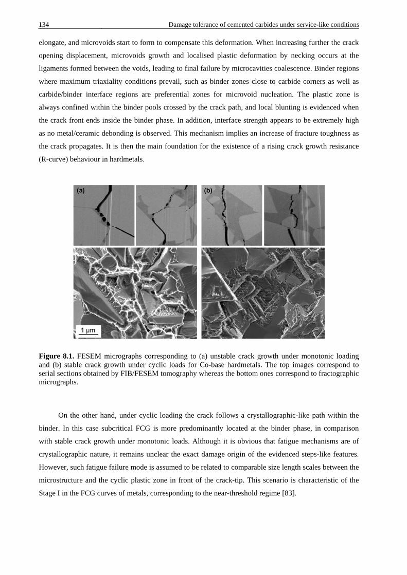
134 Damage tolerance of cemented carbides under service-like conditions elongate, and microvoids start to form to compensate this deformation. When increasing further the crack
opening displacement, microvoids growth and localised plastic deformation by necking occurs at the
ligaments formed between the voids, leading to final failure by microcavities coalescence. Binder regions
where maximum triaxiality conditions prevail, such as binder zones close to carbide corners as well as
carbide/binder interface regions are preferential zones for microvoid nucleation. The plastic zone is
always confined within the binder pools crossed by the crack path, and local blunting is evidenced when
the crack front ends inside the binder phase. In addition, interface strength appears to be extremely high
as no metal/ceramic debonding is observed. This mechanism implies an increase of fracture toughness as
the crack propagates. It is then the main foundation for the existence of a rising crack growth resistance
(R-curve) behaviour in hardmetals.
Figure 8.1. FESEM micrographs corresponding to (a) unstable crack growth under monotonic loading and (b) stable crack growth under cyclic loads for Co-base hardmetals. The top images correspond to serial sections obtained by FIB/FESEM tomography whereas the bottom ones correspond to fractographic micrographs.
On the other hand, under cyclic loading the crack follows a crystallographic-like path within the
binder. In this case subcritical FCG is more predominantly located at the binder phase, in comparison
with stable crack growth under monotonic loads. Although it is obvious that fatigue mechanisms are of
crystallographic nature, it remains unclear the exact damage origin of the evidenced steps-like features.
However, such fatigue failure mode is assumed to be related to comparable size length scales between the
microstructure and the cyclic plastic zone in front of the crack-tip. This scenario is characteristic of the
Stage I in the FCG curves of metals, corresponding to the near-threshold regime [83].

Damage tolerance of cemented carbides under service-like conditions 135
8.1.2. Influence of the microstructure on the R-curve behaviour of cemented carbides: implications on strength and reliability
One of the main purposes of this thesis is to propose an analytical model for the description of the
R-curve behaviour of hardmetals, capable of capturing microstructural effects. In doing so, in Article III
the R-curve behaviour of a Co based cemented carbide is assessed by critical analysis of FIB/FESEM
micrographs of crack-microstructure interactions taken place at the wake of stably grown cracks (e.g.
Figure 8.1a). Hence, R-curve behaviour of cemented carbides can be represented according to the
following equation:
𝐾𝐾𝑅𝑅 = 𝐾𝐾𝐼𝐼𝑐𝑐 − (𝐾𝐾𝐼𝐼𝑐𝑐 − 𝐾𝐾𝑡𝑡)𝑒𝑒𝑒𝑒𝑒𝑒 �−𝛥𝛥𝑎𝑎𝑡𝑡� (8.1)
where KR is the crack-tip resistance stress intensity factor, Kt is the critical crack-tip stress intensity
factor required for crack initiation, Δa is the subcritical crack growth, and t is a crack length normalizing
parameter assumed to be proportional to the microstructural size. According to this equation, cemented
carbides exhibit a steep but short R-curve behaviour associated with the large stresses imparted by the
highly constrained and strongly bonded bridging ligaments.
Moreover, microstructural effects on R-curve behaviour of cemented carbides and their impact on
the strength and reliability of these materials are investigated and discussed in Article IV. In doing so, R-
curve characteristics of cemented carbides are found to be strongly influenced by the microstructure. In
this regard, R-curves decrease in length but become steeper when diminishing the microstructural size.
This trend is related to a decrease of the width and an increase of the unitary strength (due to a rise of the
constraint level exerted by the carbides on the metal phase) of the metallic bridges as the binder mean free
path decreases. It is important to highlight the substantial impact of the R-curve characteristics on the
strength and reliability of cemented carbides. Hence, the fracture strength is not only found to be
dependent on the fracture toughness and the starting initial flaw size, but also notably influenced by the
effectively developed toughness level and the subcritical crack extension reached before unstable growth.
Furthermore, stable crack extension before failure results in a size homogenization of existing defects,
and consequently in an enhanced reliability.
8.1.3. Response of WC–Co micropillars to uniaxial compression
In Article II the response to uniaxial compression of WC–Co composite micropillars (of about 3
μm in diameter) consisting of Co binder regions surrounded by the contiguous ceramic particles is

136 Damage tolerance of cemented carbides under service-like conditions assessed. Main purpose behind it is to acquire a deeper knowledge on the deformation behaviour and
fracture process of the ductile metallic ligaments and the binder/carbide interface.
Compression curves (stress-strain relationships) are characterised by several pop-in events (strain
bursts) with stress values from 0.6 up to 3.1 GPa, and probably related to the activation of
shearing/cracking events. Very interesting, these stress values range between the flow stresses expected
for an unconstrained cobalt binder-like alloy and a highly constrained metallic binder. The large stress
difference evidenced between strain bursts arises on the basis of different crystal orientation and local
phase assemblage, the latter directly related to constraining degree within tested micropillars.
The fractographic inspection reveals that the boundaries, either between WC and Co or between
WC particles, are the weakest points for failure phenomena and microcrack nucleation. On the other
hand, although some signs of plasticity are evidenced in the WC phase, the biggest concentration of
plastic deformation is accumulated by the binder phase. In accordance to the observations done in Article
I, deformation within the binder tends to settle in regions close to the carbide-binder interface or at
carbides angularities, where triaxiality stress conditions reach their maximum values.
8.1.4. Fatigue sensitivity of hardmetals with Ni-containing binders
The FCG behaviour and fatigue sensitivity of a Ni-base and a series of CoNi-base hardmetals are
investigated in Articles V and VI, respectively. Results point out that cemented carbides with similar
microstructural characteristics (i.e. carbide size and binder content) exhibit similar fatigue behaviour and
fatigue sensitivity values regardless of the binder chemical nature. Therefore, for the studied materials
there exists a negligible influence of the binder chemical nature for studied hardmetals on the degradation
susceptibility of the toughening crack-bridging mechanism when subjected to fatigue loads. This fact, in
addition to the similar crystallographic fatigue failure scenario evidenced for Co- and Ni-containing
hardmetals, questions the effective action of the fcc to hcp martensitic phase transformation found in
WC–Co hardmetals as the main fatigue micromechanism.
8.1.5. Carbide mean grain size effects on crack-deflection
As previously commented, crack-deflection is an additional toughening mechanism in cemented
carbides. However, contrary to the case of crack-bridging, it is immune to fatigue loads. The effective
action of this mechanism increases for coarser microstructures and accordingly, a linear rise of the FCG
threshold with the carbide mean grain size is established in Article VI. This relation comprises carbide
mean grain sizes from 0.2 up to 4 μm, and is as follows:

Damage tolerance of cemented carbides under service-like conditions 137
𝐾𝐾𝑡𝑡ℎ = 5.75 + 1.27𝑑𝑑𝑊𝑊𝑊𝑊 (8.2)
Therefore, coarse-grained hardmetals are expected to exhibit lower fatigue sensitive values than
fine-grained ones with similar binder mean free path values.
8.1.6. Damage tolerance of cemented carbides to localised corrosion: microstructural effects
In Article VII a testing protocol for inducing controlled corrosion damage in cemented carbides is
presented. In doing so, samples are immersed in an aerated synthetic mine water solution for different
corrosion times, and tolerance to induced damage is assessed by measuring residual strength. Finally, a
detailed fractographic inspection is carried out with the purpose of identifying critical corrosion damage
that promoted failure. In Annex I the testing protocol described in Article VII is implemented in a set of
hardmetal grades having different microstructural characteristics (i.e. carbide mean grain size and binder
content). Results reveal that corrosion damage may result in relevant strength degradation in cemented
carbides on the basis of stress raising effects associated with the formation of surface corrosion pits. Thus,
as immersion time increases strength gradually decreases. However, relative changes in residual strength
become less pronounced with exposure time. Interesting, medium-sized grades exhibit much higher
damage tolerance to corrosion damage than ultrafine ones. This behaviour can be attributed to two main
factors. First, different corrosion pits geometries are evidenced between medium- and ultrafine-sized
hardmetals. In this regard, medium-sized hardmetals show semi-elliptical corrosion pits, whereas ultrafine
grades exhibit very sharp corrosion pits at the corrosion front. Second, the higher damage tolerance levels
expected for medium-sized grades as related to their higher toughness levels.
8.1.7. Corrosion phenomena in cemented carbides
A detailed description of corrosion process in cemented carbides is provided in Article VII and
Annex I through the characterization of corrosion damage-microstructure interactions by means of the 3D
FIB/FESEM serial sectioning and imaging technique. Based on the observation an analysis of gathered
micrographs, corrosion damage evolution may be described as follows: initially corrosion proceeds
through the nucleation of microcracks at the centre of binder pools, related to stress corrosion cracking
effects. Then, as corrosion time increases these microcracks tend to expand in radial directions towards
the binder/carbide interface, resulting in vast binder leaching which finally leaves an unsupported WC
grain skeleton at the surface.
138 Damage tolerance of cemented carbides under service-like conditions 8.1.8. Damage tolerance of cemented carbides to thermal shock: microstructural
effects
The influence of the microstructure on the thermal shock resistance of cemented carbides is studied
in Article VIII, through the assessment of the residual strength of hardmetal beams after being subjected
to single and repetitive severe temperature changes by water quenching. Attained results evidence that the
inducement of thermal shock damage may result in relevant strength degradation. Thermal shock damage
is speculated to be related to the nucleation of microcracks at the carbide-binder interfaces in the vicinity
of pre-existing flaws. Therefore, microcracking promotes a subcritical growth of intrinsic defects, and
consequently a strength reduction. Harder cemented carbides grades are found to exhibit a higher
resistance to the nucleation of thermal shock induced-damage. However, they also present a lower
resistance to the propagation of such damage, as compared to tougher hardmetals. These trends are in
agreement with those expected from the relative difference between their initiation (R) and propagation
(R’’’’) Hasselman’s parameters. Hence, in Article VIII thermal shock indexes are invoked, in terms of
strength- and toughness-controlled scenarios, as figures of merit for structural design with these materials.
Finally, an improved thermal shock resistance when increasing carbide mean grain size is also evidenced,
as related to higher thermal conductivity as well as enhanced damage tolerance (i.e. due to a more
prominent R-curve behaviour).
8.2. General conclusions • Unequivocal proof of the development of a multiligament zone consisting of ductile metallic enclaves
at the crack wake is provided. This toughening mechanism is the main foundation for understanding
toughness and R-curve behaviour of cemented carbides.
• A model for the description of the R-curve behaviour of hardmetals is proposed. This relation captures
microstructural effects on the R-curve characteristics of these materials. On the basis of this model, a
strong microstructural influence on the R-curve behaviour of cemented carbides is documented. It is
related to the width and strength of the ductile ligaments, the latter directly associated with the
effective constraint level exerted by the surrounding carbides over the ductile phase.
• R-curve characteristics have a relevant impact on the strength and reliability of cemented carbides. On
the one hand, fracture strength of hardmetals is substantially affected by the effectively developed
toughness level and the subcritical crack growth triggered before unstable fracture. On the other hand,
crack-bridging toughening mechanism has a beneficial effect on the reliability of hardmetals, due to

Damage tolerance of cemented carbides under service-like conditions 139
size homogenization of existing flaws, as related to stable crack extension before failure.
Consequently, the existence of such R-curve behaviour also promotes enhanced damage tolerance.
• WC–Co composite micropillars consisting of few Co binder regions surrounded by hard particles have
been successfully tested under uniaxial compression. Experimental results indicate that the interfaces
between carbide particles and between binder and carbide phases are the principal points for
irreversible deformation and failure phenomena. Stress-strain curves reveal several strain bursts at
strength values comprised between the flow stress values expected for an unconstrained Co-binder like
alloy and a highly constrained binder region in bulk WC–Co composites. This high strength scatter is
rationalised on the basis of different crystal orientation and local phase assemblage.
• Strength degradation of cemented carbides under the application of cyclic loads is principally related
to the inhibition of the crack-bridging toughening mechanism. Thus, the metallic phase is the fatigue
susceptible agent in hardmetals.
• Stable crack growth under cyclic loads follows a crystallographic path through the metallic binder.
This damage mode is speculated to be a direct consequence of the comparable size length scales for
the microstructure and the cyclic plastic zone at the crack-tip front.
• Co, CoNi and Ni binders exhibit a similar mechanical degradation as toughening agents in cemented
carbides when subjected to cyclic loads, regardless the fact that they have different damage
micromechanisms. Accordingly, Co-, CoNi- and Ni-base cemented carbides show similar fatigue
sensitivity trends.
• Crack-deflection is an additional toughening mechanism in cemented carbides immune to fatigue
loads. The effectiveness of this mechanism increases for coarser microstructures. Consequently, the
FCG threshold linearly rises with carbide mean grain size, and as a result fatigue sensitivity decreases.
• Both, localised corrosion and thermal shock damage may result in relevant strength degradation in
cemented carbides. Within this context, the microstructure plays a principal role in defining the
effective tolerance to the induced damage level.
• Strength loss associated with corrosion damage is rationalised on the basis of stress raising effects
related to corrosion pits. Semi-elliptical and sharp angular corrosion pits were identified as critical
corrosion damage for medium- and ultrafine-sized hardmetals, respectively. The latter have more

140 Damage tolerance of cemented carbides under service-like conditions
pronounced stress rising effects; and consequently, ultrafine graded cemented carbides exhibit higher
strength losses when subjected to corrosion damage.
• Thermal shock strength reduction in cemented carbides is speculated to be associated with subcritical
crack growth of pre-existing flaws, as related to localised microcracking. Harder cemented carbides
grades tend to exhibit superior resistance to thermal shock damage nucleation but lower resistance to
the propagation of such damage than tougher hardmetals. Within this context, thermal shock indexes
in terms of strength- and toughness-controlled scenarios are invoked as figures of merit for the
structural design with these materials.
8.3. Impact and perspectives One of the main outcomes of this Ph.D. thesis comes from the realisation of the requirement for
hardmetal community to gain a deeper understanding of the role of the microstructure on the evolution of
material properties and performance when inducing damage during real service-life of tools and
components. Accordingly, the basic approach based on the evaluation of microstructure-property relations
should advance towards a more realistic and application based concept. It includes the assessment of the
evolution of microstructure-property-performance interrelations as material degrades due to the harsh
working conditions to which it is subjected. Although a decisive step forward in this direction is
presented in this thesis, further and wider research should be addressed to this purpose with the aim of
covering new materials and service-like conditions. Within this context, one step further in the near future
should also include the consideration of the synergic effects between different damage mechanisms.
Following above comments, it should be underlined the breakthrough presented in this thesis
concerning the acquisition of a deep knowledge on the crack-bridging toughening mechanism in
cemented carbides, as the main foundation for understanding the fracture behaviour and damage tolerance
of these materials. In this regard, the model proposed for the description of the R-curve behaviour of
hardmetals according to their microstructural characteristics could certainly have a great impact for the
proper structural design with these materials. However, this advance only represents a closer
approximation to reality, and future efforts should be devoted to study the effects of the geometry of
critical defects on their effective action as stress raisers. That would allow rationalising the fracture
behaviour of cemented carbides on the basis of a simultaneous consideration of (1) their R-curve
characteristics, and (2) the stress raising effects associated with flaw geometry.
This Ph.D. thesis also emphasises the importance of understanding microstructure-damage relations
in hardmetals in order to set up the basis for an improved microstructural design which minimises the

Damage tolerance of cemented carbides under service-like conditions 141
adverse effects of damage-related features on the performance of engineering components. In this regard,
this work provides a detailed description of microstructure-damage interactions under the consideration of
monotonic (fracture) and cyclic (fatigue) loads as well as corrosion and thermal shock damage. Within
this context, it would be of real interest to explore other types of damage-related features and material
configurations by employing similar techniques.
There exists a growing interest on the hardmetal community to move from cobalt to alternative
binders. Nickel has attracted considerable attention as Co substitute and therefore the efforts dedicated in
this thesis to investigate the fatigue and thermal shock behaviour of cemented carbides with Ni-containing
binders would certainly be of interest to this research community. Future research should be addressed to
evaluate new binder alloys that could potentially improve the performance and life-time of hardmetal
tools and components.

142 Damage tolerance of cemented carbides under service-like conditions

Damage tolerance of cemented carbides under service-like conditions 143
Acknowledgments I would like to thank to all the people that in different ways have contributed and paid interest to the work
I have been carrying out during my last four years. It has been a great life experience, during which I have
had the opportunity to make really good friends and live unforgettable experiences. I’m fortunate of
having such incredible family, friends and colleagues. Especially, I would like to thank:
• My supervisor Luis Miguel Llanes Pitarch who gave me the opportunity to pursuit this Ph.D. I
have learned a lot from him during all these years. His support, enthusiasm, leadership and
encouragement have truly been a driving force. Even if he was extremely busy, he always found a
moment to give me advice. He gave me an excellent introduction to the art of enjoying research.
• My colleagues for all the good moments and discussions that we shared during the last years.
Special attention is given to Astrid, Carlos, Daniela, David, Erik, Erica, Giuseppe, Ina, Jing,
Joana, Miquel, Mireia, Natalia, Quentin, Roberta, Romain, Sara and Yassine. I will miss our long
coffees and Jungle Speed plays!!!
• All the members of the CIEFMA group. Above all I would like to thank Gemma Fargas, Emilio
Jiménez and Joan Josep Roa for all the fruitful collaborations and discussion we had during this
time.
• All the members of the Sandvik Hyperion R&D group for the good moments and fruitful
discussions that we always had during my visits. I sincerely appreciate the help received from my
Sandvik co-advisors, Ihsan Al-Dawery and Ludvig Schneider.
• Isaac Lopez and Trifon Trifonov for their immeasurable support with the SEM and FIB
equipment.
• My family and friends, for all their love and support.
This work was financially supported by the Spanish Ministerio de Economía y Competitividad (Grant MAT2012-34602 and MAT2015- 70780). Additionally, I would like to acknowledge the Ph.D. scholarship received from the collaborative Industry-University program between Sandvik Hyperion and Universitat Politècnica de Catalunya.

144 Damage tolerance of cemented carbides under service-like conditions

Damage tolerance of cemented carbides under service-like conditions 145
Bibliography
[1] L.S. Sigl, H.E. Exner, Experimental study of the mechanics of fracture in WC–Co alloys, Metall.
Trans. A. 18A (1987) 1299–1308.
[2] L.S. Sigl, H.F. Fischmeister, On the fracture toughness of cemented carbides, Acta Metall. 36 (1988) 887–897.
[3] A.G. Evans, Perspective on the development of high-toughness ceramics, J. Am. Ceram. Soc. 73 (1990) 187–206.
[4] L. Llanes, Y. Torres, M. Anglada, On the fatigue crack growth behavior of WC–Co cemented carbides: kinetics description, microstructural effects and fatigue sensitivity, Acta Mater. 50 (2002) 2381–2393.
[5] U. Schleinkofer, H.G. Sockel, K. Gorting, W. Heinrich, Microstructural processes during subcritical crack growth in hard metals and cermets under cyclic loads, Mater. Sci. Eng. A. 209 (1996) 103–110.
[6] E.F. Drake, A.D. Krawitz, Fatigue damage in a WC–Nickel cemented carbide composite, Metall. Mater. Trans. A. 12A (1981) 505–513.
[7] C.H. Vasel, A.D. Krawitz, E.F. Drake, E.A. Kenik, Binder deformation in WC–(Co, Ni) cemented carbide composites, Metall. Mater. Trans. A. 16A (1985) 2309–2317.
[8] Y. Torres, J.M. Tarragó, D. Coureaux, E. Tarrés, B. Roebuck, P. Chan, M. James, B. Liang, M. Tillman, R.K. Viswanadham, K.P. Mingard, A. Mestra, L. Llanes, Fracture and fatigue of rock bit cemented carbides: Mechanics and mechanisms of crack growth resistance under monotonic and cyclic loading, Int. J. Refract. Met. Hard Mater. 45 (2014) 179–188.
[9] H.E. Exner, Physical and chemical nature of cemented carbides, Int. Met. Rev. 24 (1979) 149–173.
[10] B. Roebuck, E.A. Almond, Deformation and fracture processes and the physical metallurgy of WC–Co hardmetals, Int. Mater. Rev. 33 (1988) 90–110.
[11] A.V. Shatov, S.S. Ponomarev, S.A. Firstov, Fracture and strength of hardmetals at room temperature, in: V.K. Sarin, D. Mari, L. Llanes (Eds.), Comprehensive Hard Materials, Elsevier, UK, 2014: pp. 301–343.
[12] L. Prakash, Fundamentals and general applications of hardmetals, in: V.K. Sarin, D. Mari, L. Llanes (Eds.), Comprehensive Hard Materials, Elsevier, UK, 2014: pp. 29–90.
[13] G.S. Upadhyaya, Cemented tungsten carbides: production, properties, and testing, Noyes Publications, New Jersey, USA, 1998.
[14] P. Ettmayer, H. Kolaska, H.M. Ortner, History of hardmetals, in: V.K. Sarin, D. Mari, L. Llanes (Eds.), Comprehensive Hard Materials, Elsevier, UK, 2014: pp. 3–27.

146 Damage tolerance of cemented carbides under service-like conditions [15] H.F. Fischmeister, Development and present status of the science and technology of hard
materials, in: R.K. Viswanatham, D.J. Rowcliffe, J. Gurland (Eds.), Proceedings of the 1st International Conference on the Science of Hard Materials, Plenum Press, New York, 1983: pp. 1–45.
[16] C.M. Fernandes, A.M.R. Senos, Cemented carbide phase diagrams: A review, Int. J. Refract. Met. Hard Mater. 29 (2011) 405–418.
[17] S. Norgren, J. García, A. Blomqvist, L. Yin, Trends in the P/M hard metal industry, Int. J. Refract. Met. Hard Mater. 48 (2015) 31–45.
[18] W. Schubert, E. Lassner, W. Böhlke, Cemented carbides - A success story, Tungsten. (2010).
[19] Registration, Evaluation, Authorisation and Restriction of Chemicals (REACH), http://ec.europa.eu/environment/chemicals/reach/reach_en.htm (accessed January 5, 2016).
[20] National Toxicology Program (NTP), http://ntp.niehs.nih.gov/ (accessed January 12, 2016).
[21] K. Brookes, There’s more to hard materials than tungsten carbide alone, Met. Powder Rep. 66 (2011) 36–45.
[22] K.J.A. Brookes, 3D-printing style additive manufacturing for commercial hardmetals, Met. Powder Rep. 70 (2015) 137–140.
[23] A Petersson, Cemented carbide sintering: constitutive relations and microstructural evolution. PhD Thesis, Stockholm: Royal Institute of Technology, 2004.
[24] B. Roebuck, M.G. Gee, E.G. Bennett, R. Morrell, Mechanical tests for hardmetals. NPL report, Teddington, UK, 1999.
[25] S. Lay, HRTEM investigation of dislocation interactions in WC, Int. J. Refract. Met. Hard Mater. 41 (2013) 416–421.
[26] A. Duszová, R. Halgaš, M. Bľanda, P. Hvizdoš, F. Lofaj, J. Dusza, J. Morgiel, Nanoindentation of WC–Co hardmetals, J. Eur. Ceram. Soc. 33 (2013) 2227–2232.
[27] S. Lay, J.-M. Missiaen, Microstructure and morphology of hardmetals, in: V.K. Sarin, D. Mari, L. Llanes (Eds.), Comprehensive Hard Materials, Elsevier, UK, 2014: pp. 91–120.
[28] B. Roebuck, E.A. Almond, The influence of composition, phase transformation and varying the relative F.C.C. and H.C.P. phase contents on the properties of dilute Co-W-C Alloys, Mater. Sci. Eng. 66 (1984) 179–194.
[29] K.P. Mingard, B. Roebuck, J. Marshall, G. Sweetman, Some aspects of the structure of cobalt and nickel binder phases in hardmetals, Acta Mater. 59 (2011) 2277–2290.
[30] V. Bounhoure, S. Lay, M. Loubradou, J.-M. Missiaen, Special WC/Co orientation relationships at basal facets of WC grains in WC–Co alloys, J. Mater. Sci. 43 (2007) 892–899.
[31] J. Weidow, H.-O. Andrén, Binder phase grain size in WC–Co-based cemented carbides, Scr. Mater. 63 (2010) 1165–1168.
[32] V.A. Tracey, Nickel in hardmetals, Int. J. Refract. Met. Hard Mater. 11 (1992) 137–149.
[33] E.O. Correa, J.N. Santos, A.N. Klein, Microstructure and mechanical properties of WC Ni–Si based cemented carbides developed by powder metallurgy, Int. J. Refract. Met. Hard Mater. 28 (2010) 572–575.
[34] K. Shi, K. Zhou, Z. Li, X. Zan, S. Xu, Z. Min, Effect of adding method of Cr on microstructure and properties of WC–9Ni–2Cr cemented carbides, Int. J. Refract. Met. Hard Mater. 38 (2013) 1–6.
[35] Z.Z. Fang, Correlation of transverse rupture strength of WC–Co with hardness, Int. J. Refract. Met. Hard Mater. 23 (2005) 119–127.
Damage tolerance of cemented carbides under service-like conditions 147
[36] J. Gurland, The measurement of grain contiguity in two-phase alloys, Trans AIME. 212 (1958) 452–455.
[37] A.V. Shatov, S.A. Firstov, I.V. Shatova, The shape of WC crystals in cemented carbides, Mater. Sci. Eng. A. 242 (1998) 7–14.
[38] V.T. Golovchan, N. V Litoshenko, On the contiguity of carbide phase in WC–Co hardmetals, Int. J. Refract. Met. Hard Mater. 21 (2003) 241–244.
[39] B. Roebuck, E.G. Bennett, Phase size distribution in WC-Co hardmetal, Metallography. 19 (1986) 27–47.
[40] A.V. Shatov, S.S. Ponomarev, S.A. Firstov, R. Warren, The contiguity of carbide crystals of different shapes in cemented carbides, Int. J. Refract. Met. Hard Mater. 24 (2006) 61–74.
[41] J.W. Lee, D. Jaffrey, J.D. Browne, Influence of process variables on sintering of WC–25 wt%Co, Powder Metall. 23 (1980) 57–64.
[42] J.M. Tarragó, D. Coureaux, Y. Torres, F. Wu, I. Al-Dawery, L. Llanes, Implementation of an effective time-saving two-stage methodology for microstructural characterization of cemented carbides, Int. J. Refract. Met. Hard Mater. 55 (2016) 80–86.
[43] Sandvik new developments and applications, http://www2.sandvik.com/SANDVIK/0130/Internet/SE03460.NSF/Index/4321fa9f60f7f648c125721300411c4c/$FILE/CCRD.pdf. (accessed October 30, 2015).
[44] Z.Z. Fang, M.C. Koopman, H. Wang, Cemented tungsten carbide hardmetal-an introduction, in: V.K. Sarin, D. Mari, L. Llanes (Eds.), Comprehensive Hard Materials, Elsevier, UK, 2014: pp. 123–137.
[45] P. Kenny, The application of fracture mechanics to cemented tungsten carbides, Powder Metall. 14 (1971) 22–38.
[46] H. Suzuki, K. Hayashi, The strength of WC–Co cemented carbide in relation to structural defects, Trans. Japan Inst. Met. 16 (1975) 353–360.
[47] B. Casas, X. Ramis, M. Anglada, J.M. Salla, L. Llanes, Oxidation-induced strength degradation of WC–Co hardmetals, Int. J. Refract. Met. Hard Mater. 19 (2001) 6–12.
[48] V.A. Pugsley, G. Korn, S. Luyckx, H.G. Sockel, W. Heinrich, M. Wolf, H. Feld, R. Schulte, The influence of a corrosive wood-cutting environment on the mechanical properties of hardmetal tools, Int. J. Refract. Met. Hard Mater. 19 (2001) 311–318.
[49] B. Casas, Y. Torres, L. Llanes, Fracture and fatigue behavior of electrical-discharge machined cemented carbides, Int. J. Refract. Met. Hard Mater. 24 (2006) 162–167.
[50] A. Góez, D. Coureaux, A. Ingebrand, B. Reig, E. Tarrés, A. Mestra, A. Mateo, E. Jiménez-Piqué, L. Llanes, Contact damage and residual strength in hardmetals, Int. J. Refract. Met. Hard Mater. 30 (2012) 121–127.
[51] J.-L. Chermant, A. Deschanvres, A. Iost, R. Meyer, Tenacite de WC–Co 15 %, Mater. Res. Bull. 8 (1973) 925–934.
[52] H.E. Exner, A. Walter, R. Pabst, Zur ermittlung und darstellung der Fehlerverteilungen von spröden werkstoffen, Mater. Sci. Eng. 16 (1974) 231–238.
[53] N. Ingleström, H. Nordberg, The fracture toughness of cemented carbides, Eng. Fract. Mech. 6 (1974) 597–607.
[54] G.R. Irwin, Fracture, in: Handbuch Der Physics, Springer-Verlag, Berlin, 1958.
[55] R.O. Ritchie, The conflicts between strength and toughness, Nat. Mater. 10 (2011) 817–822.

148 Damage tolerance of cemented carbides under service-like conditions [56] A.G. Evans, A.H. Heuer, D.L. Porter, The fracture toughness of ceramics, in: D.M.R. Taplin (Ed.),
Proceedings of the 4th International Conference in Fracture, Pergamon, Waterloo, Canada, 1977: pp. 529–556.
[57] R.K. Viswanadham, T.S. Sun, E.F. Drake, J. Peck, Quantitative fractography of WC-Co cermets by Auger spectroscopy, J. Mater. Sci. 16 (1981) 1029–1038.
[58] V.D. Krstic, On the fracture of brittle-matrix/ductile-particle composites, Philos. Mag. A. 48 (1983) 695–708.
[59] A.G. Evans, R.M. McMeeking, On the toughening of ceramics by strong reinforcements, Acta Metall. 34 (1986) 2435–2441.
[60] L.S. Sigl, P.A. Mataga, B.J. Dalgleish, R.M. McMeeking, A.G. Evans, On the toughness of brittle materials reinforced with a ductile phase, Acta Metall. 36 (1988) 945–953.
[61] M.F. Ashby, F.J. Blunt, M. Bannister, Flow characteriztics of highly constrained metal wires, Acta Metall. 37 (1989) 1847–1857.
[62] H.F. Fischmeister, S. Schmauder, L.S. Sigl, Finite element modelling of crack propagation in WC–Co hard metals, Mater. Sci. Eng. A. 105/106 (1988) 305–311.
[63] C. McVeigh, W.K. Liu, Multiresolution modeling of ductile reinforced brittle composites, J. Mech. Phys. Solids. 57 (2009) 244–267.
[64] O. Raddatz, G.A. Schneider, N. Claussen, Modelling of R-curve behavior in ceramic/metal composites, Acta Metall. 46 (1998) 6381–6395.
[65] D. Munz, What can we learn from R-curve measurements?, J. Am. Ceram. Soc. 90 (2007) 1–15.
[66] H.G. Schmid, The mechanisms of fracture of WC–11wt%Co between 20oC and 1000oC, Mater. Forum. 10 (1987) 184–197.
[67] P.A. Mataga, Deformation of crack-bridging ductile reinforcements in toughened brittle materials, Acta Metall. 37 (1989) 3349–3359.
[68] Y. Torres, D. Casellas, M. Anglada, L. Llanes, Fracture behavior of hardmetals: implementation of flaw configuration modeling and R-Curve concepts, in: H. Danninger, R. Ratzi (Eds.), Proceedings of the EuroPM 2004, EPMA, Vienna, Austria, 2004: pp. 551–556.
[69] Y. Torres, R. Bermejo, L. Llanes, M. Anglada, Influence of notch radius and R-curve behaviour on the fracture toughness evaluation of WC–Co cemented carbides, Eng. Fract. Mech. 75 (2008) 4422–4430.
[70] G.R. Odette, B.L. Chao, J.W. Sheckherd, G.E. Lucas, Ductile phase toughening mechanisms in a TiAl-TiNb laminate composite, Acta Metall. Mater. 40 (1992) 2381–2389.
[71] R.O. Ritchie, K.J. Koester, S. Ionova, W. Yao, N.E. Lane, J.W. Ager, Measurement of the toughness of bone: a tutorial with special reference to small animal studies, Bone. 43 (2008) 798–812.
[72] M.E. Launey, R.O. Ritchie, On the fracture toughness of advanced materials, Adv. Mater. 21 (2009) 2103–2110.
[73] D. Rubes, B. Smoljan, R. Danzer, Main features of designing with brittle materials, J. Mater. Eng. Perform. 12 (2003) 220–228.
[74] E.A. Almond, B. Roebuck, Defect-initiated fracture and the bend strength of WC–Co hardmetals, Met. Sci. 11 (1977) 458–461.
[75] T. Klünsner, S. Wurster, P. Supancic, R. Ebner, M. Jenko, J. Glätzle, A. Püschel, R. Pippan, Effect of specimen size on the tensile strength of WC–Co hard metal, Acta Mater. 59 (2011) 4244–4252.
[76] Y. Torres, R. Bermejo, F.J. Gotor, E. Chicardi, L. Llanes, Analysis on the mechanical strength of WC-Co cemented carbides under uniaxial and biaxial bending, Mater. Des. 55 (2014) 851–856.

Damage tolerance of cemented carbides under service-like conditions 149
[77] R. Danzer, T. Lube, P. Supancic, R. Damani, Fracture of ceramics, Adv. Eng. Mater. 10 (2008) 275–298.
[78] W. Weibull, A statistical distribution function of wide applicability, J. Appl. Mech. 18 (1951) 293–297.
[79] J.B. Wachtman, Mechanical properties of ceramics, 2nd ed., John Wiley & Sons, New York, 1996.
[80] ASTM C 1239-00: Standard practice for reporting uniaxial strength data and estimating Weibull distribution parameters for advanced ceramics, USA, 2000.
[81] R. Danzer, P. Supancic, J. Pascual, T. Lube, Fracture statistics of ceramics – Weibull statistics and deviations from Weibull statistics, Eng. Fract. Mech. 74 (2007) 2919–2932.
[82] L. Llanes, M. Anglada, Y. Torres, Fatigue of cemented carbides, in: V.K. Sarin, D. Mari, L. Llanes (Eds.), Comprehensive Hard Materials, Elsevier, UK, 2014: pp. 345–362.
[83] S. Suresh, Fatigue of materials, 2nd ed., Cambridge University press, New York, 1998.
[84] W. Dawihl, Die wissenschaftlichen und technischen grudlagen der pulvermetallurgic und ihrer anwendungsbereiche, Stahl U. Eisen. 61 (1941) 909–919.
[85] U. Schleinkofer, H.G. Sockel, K. Gorting, W. Heinrich, Fatigue of hard metals and cermets, Mater. Sci. Eng. A. 209 (1996) 313–317.
[86] U. Schleinkofer, H.G. Sockel, K. Görting, W. Heinrich, Fatigue of hard metals and cermets - new results and a better understanding, Int. J. Refract. Met. Hard Mater. 15 (1997) 103–112.
[87] P. Schlund, P. Kindermann, H.-G. Sockel, U. Schleinkofer, W. Heinrich, K. Görting, Mechanical behaviour of PVD- and CVD-coated hard metals under cyclic loads, Int. J. Refract. Met. Hard Mater. 17 (1999) 193–199.
[88] P. Kindermann, P. Schlund, H.-G. Sockel, M. Herr, W. Heinrich, K. Görting, U. Schleinkofer, High-temperature fatigue of cemented carbides under cyclic loads, Int. J. Refract. Met. Hard Mater. 17 (1999) 55–68.
[89] G. Erling, S. Kursawe, S. Luyck, H.G. Sockel, Stable and unstable fracture surface features in WC–Co, J. Mater. Sci. Lett. 19 (2000) 437–438.
[90] S. Kursawe, P. Pott, H.G. Sockel, W. Heinrich, M. Wolf, On the influence of binder content and binder composition on the mechanical properties of hardmetals, Int. J. Refract. Met. Hard Mater. 19 (2001) 335–340.
[91] T. Sailer, M. Herr, H.-G. Sockel, R. Schulte, H. Feld, L.J. Prakash, Microstructure and mechanical properties of ultrafine-grained hardmetals, Int. J. Refract. Met. Hard Mater. 19 (2001) 553–559.
[92] R.K. Viswanadham, T.S. Sun, E.F. Drake, A. Peck, J. Peck, Quantitative fractography of WC–Co cermets by Auger spectroscopy, J. Mater. Sci. 16 (1981) 1029–1038.
[93] R. V Marrey, R. Burgermeister, R.B. Grishaber, R.O. Ritchie, Fatigue and life prediction for cobalt-chromium stents: A fracture mechanics analysis, Biomaterials. 27 (2006) 1988–2000.
[94] R.O. Ritchie, Mechanisms of fatigue-crack propagation in ductile and brittle solids, Int. J. Fract. 100 (1999) 55–83.
[95] E.A. Almond, B. Roebuck, Fatigue-crack growth in WC–Co hardmetals, Met. Technol. 2 (1980) 83–85.
[96] P.R. Fry, G.G. Garret, Fatigue crack growth behaviour of tungsten carbide-cobalt hardmetals, J. Mater. Sci. 23 (1988) 2325–2338.
[97] Y. Torres, M. Anglada, L. Llanes, Fatigue mechanics of WC–Co cemented carbides, Int. J. Refract. Met. Hard Mater. 19 (2001) 341–348.

150 Damage tolerance of cemented carbides under service-like conditions [98] Y. Torres, M. Anglada, L. Llanes, Fatigue limit - fatigue crack growth threshold correlation for
hardmetals: influence of microstructure, in: A.F. Blom (Ed.), Proceedings of the 8th International Fatigue Congress, EMAS, Stockholm, 2002.
[99] Y. Torres, V.K. Sarin, M. Anglada, L. Llanes, Loading mode effects on the fracture toughness and fatigue crack growth resistance of WC–Co cemented carbides, Scr. Mater. 52 (2005) 1087–1091.
[100] U. Beste, T. Hartzell, H. Engqvist, N. Axén, Surface damage on cemented carbide rock-drill buttons, Wear. 249 (2001) 324–329.
[101] R. Lu, L. Minarro, Y.-Y. Su, R.M. Shemenski, Failure mechanism of cemented tungsten carbide dies in wet drawing process of steel cord filament, Int. J. Refract. Met. Hard Mater. 26 (2008) 589–600.
[102] V.A. Pugsley, H.-G. Sockel, Corrosion fatigue of cemented carbide cutting tool materials, Mater. Sci. Eng. A. 366 (2004) 87–95.
[103] M. Lagerquist, A study of the thermal fatigue crack propagation in WC–Co cemented carbide, Powder Metall. 18 (1975) 75–87.
[104] H. Chandrasekaran, Fracture of carbide tools in intermittent cutting, in: R.K. Viswanadham, D.J. Rowcliffe, J. Gurland (Eds.), Proceedings of the 1st International Conference on the Science of Hard Materials, Plenum Press, New York, 1983: pp. 735–755.
[105] A.C.A. Melo, J.C.G. Milan, M.B. Silva, A.R. Machado, Some observations on wear and damages in cemented carbide tools, J. Brazilian Soc. Mech. Sci. Eng. 28 (2006) 269–277.
[106] W.J. Tomlinson, C.R. Linzell, Anodic polarisation and corrosion of cemented carbides with cobalt and nickel binders, J. Mater. Sci. 23 (1988) 914–918.
[107] A.M.M. Human, H.E.E. Exner, The relationship between electrochemical behaviour and in-service corrosion of WC based cemented carbides, Int. J. Refract. Met. Hard Mater. 15 (1997) 65–71.
[108] S. Hochstrasser(-Kurz), Y. Mueller, C. Latkoczy, S. Virtanen, P. Schmutz, Analytical characterization of the corrosion mechanisms of WC–Co by electrochemical methods and inductively coupled plasma mass spectroscopy, Corros. Sci. 49 (2007) 2002–2020.
[109] W.J. Tomlinson, N.J. Ayerst, Anodic polarization and corrosion of WC–Co hardmetals containing small amounts of Cr3C2 and/or VC, J. Mater. Sci. 24 (1989) 2348–2352.
[110] H. Engqvist, U. Beste, N. Axén, The influence of pH on sliding wear of WC-based materials, Int. J. Refract. Met. Hard Mater. 18 (2000) 103–109.
[111] F.J.J. Kellner, H. Hildebrand, S. Virtanen, Effect of WC grain size on the corrosion behavior of WC–Co based hardmetals in alkaline solutions, Int. J. Refract. Met. Hard Mater. 27 (2009) 806–812.
[112] A.M. Human, I.T. Northrop, S. Luyckx, M.N. James, A comparaison between cemented carbides containing Cobalt- and Nickel-based binders, J. Hard Mater. 2 (1991) 245–256.
[113] H. Scholl, B. Hofman, A. Rauscher, Anodic polarization of cemented carbides of the type [(WC,M): M = Fe, Ni or Co] in sulphuric acid solution, Electrochim. Acta. 37 (1992) 447–452.
[114] B. Bozzini, G.P. De Gaudenzi, M. Serra, A. Fanigliulo, F. Bogani, Corrosion behaviour of WC–Co based hardmetal in neutral chloride and acid sulphate media, Mater. Corros. 53 (2002) 328–334.
[115] F.J.J. Kellner, M.S. Killian, G. Yang, E. Spiecker, S. Virtanen, TEM and ToF-SIMS studies on the corrosion behavior of vanadium and chromium containing WC–Co hard metals in alkaline solutions, Int. J. Refract. Met. Hard Mater. 29 (2011) 376–383.
[116] S. Sutthiruangwong, G. Mori, R. Kösters, Passivity and pseudopassivity of cemented carbides, Int. J. Refract. Met. Hard Mater. 23 (2005) 129–136.

Damage tolerance of cemented carbides under service-like conditions 151
[117] A. Bock, W.D. Schubert, B. Lux, Inhibition of grain growth on submicron cemented carbides, Powder Met. 24 (1992) 20–26.
[118] B. Wittmann, W.-D. Schubert, B. Lux, WC grain growth and grain growth inhibition in nickel and iron binder hardmetals, Int. J. Refract. Met. Hard Mater. 20 (2002) 51–60.
[119] C.W. Morton, D.J. Wills, K. Stjernberg, The temperature ranges for maximum effectiveness of grain growth inhibitors in WC–Co alloys, Int. J. Refract. Met. Hard Mater. 23 (2005) 287–293.
[120] Z. Guo, J. Xiong, M. Yang, X. Song, C. Jiang, Effect of Mo2C on the microstructure and properties of WC–TiC–Ni cemented carbide, Int. J. Refract. Met. Hard Mater. 26 (2008) 601–605.
[121] Q. Zhang, N. Lin, Y. He, Effects of Mo additions on the corrosion behavior of WC–TiC–Ni hardmetals in acidic solutions, Int. J. Refract. Met. Hard Mater. 38 (2013) 15–25.
[122] A.M. Human, H.E. Exner, Electrochemical behaviour of tungsten-carbide hardmetals, Mater. Sci. Eng. A. 209 (1996) 180–191.
[123] S. Sutthiruangwong, G. Mori, Corrosion properties of Co-based cemented carbides in acidic solutions, Int. J. Refract. Met. Hard Mater. 21 (2003) 135–145.
[124] E.J. Wentzel, C. Allen, Erosion-corrosion resistance of tungsten carbide hard metals with different binder compositions, Wear. 181-183 (1995) 63–69.
[125] A.J. Gant, M.G. Gee, A.T. May, The evaluation of tribo-corrosion synergy for WC–Co hardmetals in low stress abrasion, Wear. 256 (2004) 500–516.
[126] M.R. Thakare, J.A. Wharton, R.J.K. Wood, C. Menger, Exposure effects of alkaline drilling fluid on the microscale abrasion–corrosion of WC-based hardmetals, Wear. 263 (2007) 125–136.
[127] W.J. Tomlinson, I.D. Molyneux, Corrosion, erosion-corrosion, and the flexural strength of WC–Co hardmetals, J. Mater. Sci. 26 (1991) 1605–1608.
[128] Y.W. Mai, Thermal-shock resistance and fracture-strength behavior of two tool carbides, J. Am. Ceram. Soc. 59 (1976) 1–4.
[129] C.W. Merten, Response of a WC–Co alloy to thermal shock, in: R.K. Viswanadham, D.J. Rowcliffe, J. Gurland (Eds.), Proceedings of the 1st International Conference on the Science of Hard Materials, Plenum Press, New York, 1983: pp. 757–774.
[130] D. Hand, J.J. Mecholsky, Strength and toughness degradation of a tungsten carbide-cobalt due to thermal shock, J. Am. Ceram. Soc. 73 (1990) 3692–3695.
[131] S. Ishihara, T. Goshima, K. Miyao, T. Yoshimoto, S. Takehana, Study on the thermal shock behavior of cermets and cemented carbides, Japan Soc. Mech. Eng. Solid Mech. Mater. Eng. 34 (1991) 490–495.
[132] S. Ishihara, T. Goshima, K. Nomura, T. Yoshimoto, Crack propagation behavior of cermets and cemented carbides under repeated thermal shocks by the improved quench test, J. Mater. Sci. 34 (1999) 629–636.
[133] T. Yoshimoto, S. Ishihara, T. Goshima, A.J. McEvily, T. Ishizaki, An improved method for the determination of the maximum thermal stress induced during a quench test, Scr. Mater. 41 (1999) 553–559.
[134] S. Ishihara, H. Shibata, T. Goshima, A.J. McEvily, Thermal shock induced microcracking of cermets and cemented carbides, Scr. Mater. 52 (2005) 559–563.
[135] ASTM C1525 - 04: Standard test method for determination of thermal shock resistance for advanced ceramics by water quenching, USA, 2014.
[136] W.R. Buessem, Thermal shock testing, J. Am. Ceram. Soc. 38 (1955) 15–17.
[137] W.D. Kingery, Factors affecting thermal stress resistance, J. Am. Ceram. Soc. 38 (1955) 3–15.

152 Damage tolerance of cemented carbides under service-like conditions [138] D.P. Hasselman, Elastic energy at fracture and surface energy as design criteria for thermal shock,
J. Am. Ceram. Soc. 46 (1963) 535–540.
[139] D.P. Hasselman, Unified theory of thermal shock fracture initiation and crack propagation in brittle ceramics, J. Am. Ceram. Soc. 52 (1969) 600–604.
[140] Z.-H. Jin, Y.-W. Mai, Effects of damage on thermal shock strength behavior of ceramics, J. Am. Ceram. Soc. 78 (1995) 1873–1881.
[141] P.R. Munroe, The application of focused ion beam microscopy in the material sciences, Mater. Charact. 60 (2009) 2–13.
[142] R. Wirth, Focused Ion Beam (FIB) combined with SEM and TEM: Advanced analytical tools for studies of chemical composition, microstructure and crystal structure in geomaterials on a nanometre scale, Chem. Geol. 261 (2009) 217–229.
[143] N. Yao, Focused Ion Beam systems: basics and applications, Cambridge University Press, Cambridge, 2007.
[144] ISO 4499 - 2 Hardmetals. Metallographic determination of microstructure. Part 2: Measurement of WC grain size, Switzerland, 2008.
[145] D. Coureaux, Comportamiento mecánico de carburos cementados WC–Co: Influencia de la microestructura en la resistencia a la fractura, la sensibilidad a la fatiga y la tolerancia al daño inducido bajo solicitaciones de contacto. PhD Thesis, Universitat Politècnica de Catalunya, 2012.
[146] ASTM C1161 - 02c: Standard test method for flexural strength of advanced ceramics at ambient temperatures, USA, 2008.
[147] Y. Torres, D. Casellas, M. Anglada, L. Llanes, Fracture toughness evaluation of hardmetals: influence of testing procedure, Int. J. Refract. Met. Hard Mater. 19 (2001) 27–34.
[148] ASTM E399 - 09: Standard test method for linear-elastic plane-strain fracture toughness KIc of metallic materials, USA, 2009.
[149] K.J.A. Brookes, Corrosion damage in WC/Co, Met. Powder Rep. 70 (2015) 82–87.
Damage tolerance of cemented carbides under service-like conditions 153
Annex I
Microstructural influence on tolerance to corrosion-induced damage in hardmetals
1. Introduction
Cemented carbides, also referred to as hardmetals, are a group of ceramic-metal composite
materials that exhibit an outstanding combination of hardness, wear resistance and toughness [1–3]. Their
unique combination of properties has made of them the preferential choice in a large number of industrial
applications demanding high performance under harsh working conditions, e.g. cutting and forming tools,
mining bits and mechanical seals [4,5]. Hardmetals composite nature consists of hard and brittle ceramic
particles (generally WC) embedded into a ductile metallic matrix forming two interpenetrating networks.
The preferential choice for the ductile binder is Co but binders of different chemical nature (e.g. Ni,
CoNi) are used in applications demanding enhanced performance under certain severe working
conditions, such as corrosive environments and high temperatures [6].
Cemented carbides tools and components are frequently exposed to chemically aggressive media
including a large variety of corrosive environments, such as lubricants, chemical and petrochemical
products as well as mine- and sea- water (e.g. Refs. [7–10]). Therefore, it is of crucial importance to
improve the corrosion resistance of cemented carbides in order to increase their service life and to prevent
premature failure of tools and components. In acidic and neutral pH solutions, hardmetals corrosion
process consists on a galvanic couple where the binder is selectively attacked due to its anodic role [11–
14], whereas WC particles are cathodically protected [13]. In addition, due to the larger surface area
covered by ceramic particles, corrosion in the anodic sites gets enhanced [13]. The opposite trend is found
in basic solutions, where ceramic particles dissolve and the binder phase passivates [15,16]. Corrosion
mechanisms in cemented carbides are really complex and depend on a large number of factors such as
surface state, corrosive medium, hardmetal microstructure and binder chemical nature. Furthermore,
corrosion system is in constant evolution due to the continuous changes produced by the cathodic and
anodic reactions taking place at the surface [13].

154 Damage tolerance of cemented carbides under service-like conditions
In-service performance of cemented carbides is not only dependent on their intrinsic mechanical
properties but also is highly influenced by their resistance to the aggressive medium to which they are
exposed. Within this context, corrosion attack exposes WC grains, resulting in a noticeable increase of
wear rates. Accordingly, several studies have been focused on studying the synergic effects between
erosion/abrasion and corrosion on the wear rates of cemented carbides (e.g. Refs. [15–19]). Cemented
carbides exhibit brittle fracture behaviour related to the propagation of pre-existing flaws which may be
processing-, shaping- or service- induced defects (e.g. Refs. [2,8,20–24]). Therefore, corrosion damage
may also induce a detrimental effect on the strength and fatigue resistance of hardmetals due to the
formation of corrosion pits with pronounced stress rising effects [8,9,25–27]. Thus, localized corrosion
damage may have a critical role as a critical flaw, promoting a premature and un-expected failure
[8,9,25,27]. However, to the best knowledge of the authors, only two studies have been addressed to
correlate strength reduction and corrosion damage in cemented carbides, and both of them point out
relevant strength degradation due to the stress rising effects produced by localized corrosion damage
[8,27]. Thus, from a structural integrity perspective, it is essential to understand the detrimental impact
that corrosion damage may induce in the performance of cemented carbides components.
The combined use of Focused Ion Beam (FIB) and Field Emission Scanning Electron Microscopy
(FESEM) has been proved as an extremely useful technique for characterizing microstructure [28,29] and
damage phenomena [19,27,28,30–32] in cemented carbides. Following the above ideas, the aim of this
investigation is two-fold: (1) to provide a thorough characterization of corrosion damage in cemented
carbides immersed in a mine water solution, and (2) to study the detrimental effects of corrosion as a
degrading factor of their mechanical performance. Within this purpose, the corrosion behaviour of five
WC-Co cemented carbide grades having different microstructural characteristics was first investigated by
means of electrochemical measurements. Then, retained strength after the inducement of corrosion
damage was assessed and a corresponding fractographic analysis was conducted. Finally, a detailed
characterization of corrosion damage-microstructure interactions in cemented carbides was done from
tomographic reconstructions obtained by means of 3D FIB/FESEM serial sectioning and imaging.
2. Materials and experimental aspects
Carbide mean grain size (dWC) and the binder content (%wt.), are the principal parameters involved
in the definition of the microstructural assemblage of WC-Co hardmetals. Thus, in order to investigate the
influence of the microstructure on the corrosion damage of cemented carbides, five experimental WC-Co
hardmetal grades having different combinations of binder content and mean grain size were studied. All
materials were supplied by Sandvik Hyperion. Main microstructural characteristics, including specimen
designations, binder content, carbide mean grain size, contiguity (CWC) and binder mean free path (λCo)
are detailed in Table 1. Mean grain size was measured following the linear intercept method, using field

Damage tolerance of cemented carbides under service-like conditions 155
emission scanning electron microscopy (FESEM) micrographs. On the other hand, carbide contiguity and
binder mean free path were deduced following empirical relationships given in the literature [2,33]. A
small amount of Cr3C2 (i.e. around a 5%wt. of the binder content) was added to the composition of 11M,
15UF, 10UF and 3UF grades as a grain growth inhibitor.
Specimen Code
Binder content (%wt.)
dWC
(μm) CWC λbinder
(μm) 15M 15 1.15 ± 0.92 0.30 ± 0.07 0.55 ± 0.46
11M* 11 1.12 ± 0.71 0.38 ± 0.07 0.42 ± 0.28 15UF* 15 0.47 ± 0.22 0.36 ± 0.02 0.24 ± 0.11 10UF* 10 0.39 ± 0.19 0.46 ± 0.06 0.16 ± 0.06 3UF* 3 0.37 ± 0.09 0.59 ± 0.12 0.08 ± 0.03
Table 1. Nomenclature and microstructural parameters for investigated cemented carbides. *Presence of Cr3C2 in the composition as a grain growth inhibitor.
Corrosion behaviour was first studied on the basis of electrochemical response of the grades under
consideration. Corrosive media consisted on synthetic mine water solution (SMW) (pH = 6.3) containing
dissolved salts whose composition is detailed in Table 2 [12,34]. The potentiodynamic polarization
technique was applied to study the corrosion resistance of the investigated cemented carbides in the
aerated SMW solution at room temperature. The electrochemical tests were carried out using a standard
three electrode system in which the test specimen was the working electrode, a platinum plate was the
counter electrode and a silver/silver chloride electrode was used as the reference electrode. After
immersion in the electrolyte, the open circuit potential was stabilized during 30 minutes. Subsequently,
the sample was polarized into the cathodic region at -500 mV. Then, the potential was increased towards
the anodic region with a scan rate of 600 mV/h in the positive direction up to 500 mV.
Compound Concentration
(mg/L) CaCl2 1058
Na2SO4 1237 MgSO4 199 NaCl 1380
Table 2. Synthetic mine water solution composition [11].
Different levels of corrosion damage were induced through simple immersion of specimens in the
stirred synthetic mine water corrosive media. Weight loss was measured after immersion tests performed
from 24 to 360 h. Before and after immersion tests, the specimens were first hand-cleaned by using soapy

156 Damage tolerance of cemented carbides under service-like conditions water and then ultrasonically cleaned for 15 min in ethanol, subsequently dried with a pure air, and
weighted in an electronic balance having a resolution of ± 0.1 mg. Corrosion rates were estimated using
the following equation:
𝐶𝐶𝐶𝐶𝐶𝐶𝐶𝐶𝐶𝐶𝐶𝐶𝐶𝐶𝐶𝐶𝐶𝐶 𝐶𝐶𝑎𝑎𝑟𝑟𝑒𝑒 (𝑚𝑚𝑚𝑚 𝑦𝑦𝑒𝑒𝑎𝑎𝐶𝐶⁄ ) = 87.6 �𝑤𝑤𝐴𝐴𝜌𝜌𝑟𝑟
� (1)
where w is the weight loss in mg; A is the surface area of the specimen in cm2; ρ is the density of the
material in g/cm3; and t is the corrosion time in hours.
After immersion tests, retained flexural strength (σr) was assessed. At least three samples were
tested per investigated material and corrosion time. Flexural strength was determined by subjecting 4 mm
x 3 mm x 45 mm specimens to failure using a four-point bending fully articulated test jig with inner and
outer spans of 20 and 40 mm, respectively. Subsequently, a detailed FESEM fractographic inspection was
conducted with the purpose of characterizing corrosion damage as well as to discern critical failure sites.
Strength data was also assessed for non-corroded specimens (reference) and at least 15 samples were
tested per studied grade. Here, the surface which was later subjected to the maximum tensile load was
polished to mirror-like finish and the edges were chamfered to reduce their effect as stress raisers. Besides
fracture strength, each grade was mechanically characterized in terms of hardness and fracture toughness.
Hardness (HV30) was measured using a Vickers indenter and applying a load of 294N. Fracture
toughness (KIc) was determined using 5 mm x 10 mm x 45 mm single edge pre-cracked beam (SEPB)
specimens and details on the procedure may be found elsewhere [35]. In this case, five samples were
tested per material.
Figure 1. FESEM micrograph corresponding to the selected region of interest for 3D reconstruction on the 15M hardmetal corroded for 7 days.
2 μm

Damage tolerance of cemented carbides under service-like conditions 157
One of the main goals of this investigation is to conduct a detailed characterization of corrosion
damage in cemented carbides by performing a 3D reconstruction of corrosion damage-microstructure
interactions. In doing so, the serial sectioning and imaging technique was implemented in a FIB/FESEM
(Zeiss Neon 40) equipment. Two samples were selected for the tomographic reconstruction,
corresponding to the 15M grade immersed in the synthetic mine water solution for 7 and 15 days.
Initially, an inspection of the corroded surface was carried out in order to select a small area of interest (of
about 12 μm x 12 μm) for the reconstruction (e.g. Figure 1). Before ion milling, a thin protective
platinum layer was deposited on the area of interest. Then, a U-shaped trench with one cross-sectional
surface (perpendicular to specimen surface) was produced by FIB (Figure 2). Subsequently, a series of
micrographs were obtained by periodic removal of the material by FIB, within the U-shaped crater
parallel to the cross-sectional surface. An example of obtained micrographs is shown for both, 7 and 15
days, in Figure 3. A total volume of about 12 µm × 12 µm × 10 µm was ion milled and around 600
images were obtained with a span of about 20 nm between them. The 3D reconstruction of the images
was carried out using the commercial Avizo software. Obtained micrographs were aligned and a series of
image processing techniques were implemented in order to correct, equalize, and differentiate the grey
levels associated with each phase (WC, cobalt, corroded cobalt and microcracks). The next step consisted
of segmenting these phases to finally reconstruct the 3D volume.
Figure 2. FESEM image of the trench generated by FIB, previous to sequential milling around the region of interest for the 15M hardmetal corroded for 7 days.
5 μm

158 Damage tolerance of cemented carbides under service-like conditions
Figure 3. Micrographs showing corrosion damage–microstructure interactions on serial sections obtained by means of FIB/FESEM after being filtered.
3. Results and discussion 3.1. Corrosion behaviour
The measured corrosion rates for the studied materials are shown in Figure 4. It can be observed
that the investigated 15M hardmetal grade exhibit much higher corrosion rates than the other studied
materials. Indeed, during sintering chromium dissolves into the binder and that result in a beneficial effect
against corrosion [36,37]. TEM analysis performed by Suttihiruangwong et al. demonstrated the
formation of a passivating Co-based chromium oxide layer film at the binder surface which strongly
decreased the rate of dissolution of the binder, and hence the improved corrosion resistance of Cr-
containing cemented carbides [37]. On the other hand, the other materials showed similar corrosion rates.
A small decrease of corrosion rates with grain size was evidenced when comparing 11M and 10UF
grades. Contradictory results may be found in literature regarding the effect of grain size on the corrosion
resistance of hardmetals [12,36]. On one hand Human and Exner [12] documented, on the basis of
electrochemical measurements, that the WC mean size does not have a significant effect on the corrosion
rates of cemented carbides. On the other hand, Tomlinson and Ayerst pointed out an increase of corrosion
rates with grain size [36]. As discussed below, this slightly decrease in corrosion rates observed for the
ultrafine grades may be related to the pseudopassive behaviour evidenced for these materials. As
expected, a decrease of the corrosion rates when decreasing the binder content was also evidenced. This
decrease is related to a lower binder surface area exposed to the corrosive media, even though the
decrease of the metallic phase surface area enhances the galvanic couple effect between WC and Co
phases [13].

Damage tolerance of cemented carbides under service-like conditions 159
Figure 4. Corrosion rates as a function of immersion time for the studied cemented carbides.
The electrochemical parameters measured for the studied cemented carbides are listed in Table 3.
They include corrosion potential (Ecorr), corrosion current density (icorr), critical current density (ic) and
minimum current density in pseudopassive region (ipp). As an example, the potentiodynamic polarisation
curves obtained for the 15M and 15UF grades are shown in Figure 5. It can be observed that the presence
of chromium in the binder leads to lower values of the corrosion current density, as evidenced when
comparing 11M and 15M grades [38]. Very interesting, pseudopassivation phenomenon was only
discerned for the ultrafine grades. This is particularly clear in Figure 5, where a continuous anodic
dissolution is observed for the 15M hardmetal, while the current density for the 15UF grade drops to
lower values after achieving the critical current density. In agreement with previous results [39],
pseudopassivation phenomenon is a consequence of a limitation of the cobalt diffusion that causes a
decrease of the current flow. After the dissolution of the cobalt present at the surface, the current flow is
limited because cobalt has to diffuse throughout the remaining porous tungsten carbide skeleton. Thus,
when the binder mean free path gets shorter, as it is the case for the ultrafine grades, cobalt diffusion gets
lessened. On the other hand, 15M did not show a pseudopassivation phenomenon. In addition, it is
interesting to notice that ultrafine grades exhibit less negative Ecorr, i.e. more noble values, than medium
ones for similar binder contents (see Table 3), which yields lower corrosion current densities.

160 Damage tolerance of cemented carbides under service-like conditions
Specimen code Ecorr (mV) icorr (µA/cm2) ic (mA/cm2) ipp (mA/cm2) 15M -287 6.23 3.72 - 11M -291 2.87 3.51 - 15UF -274 3.64 0.56 0.23 10UF -264 2.41 0.40 0.18 3UF -268 1.13 0.51 0.16
Table 3. Electrochemical parameters of the studied cemented carbides. They include corrosion potential (Ecorr), corrosion current density (icorr), critical current density (ic) and minimum current density in pseudopassive region (ipp).
Figure 5. Potentiodynamic polarisation of 15M and 15UF alloys in synthetic mine water.
3.2. Residual strength of corroded hardmetals
The mechanical characterization of investigated materials prior to immersion tests includes the
assessment of their hardness, fracture toughness, flexural strength and Weibull modulus. Obtained results
are listed in Table 4. As expected, hardness rises and fracture toughness decreases when the binder mean
free path gets shorter [2]. The tougher grades exhibited extremely high Weibull modulus values, whereas
the higher strength scatters were measured for the harder hardmetals.
-600 -450 -300 -150 0 150 300 450 600
1E-5
1E-4
1E-3
0,01
0,1
1
10
100
Curre
nt d
ensit
y (m
A/cm
2 )
E Ag/AgCl (mV)
15M 15UF
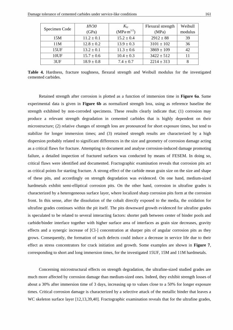
Damage tolerance of cemented carbides under service-like conditions 161
Specimen Code HV30 (GPa)
KIc (MPa·m1/2)
Flexural strength (MPa)
Weibull modulus
15M 11.2 ± 0.1 15.2 ± 0.4 2912 ± 88 39 11M 12.8 ± 0.2 13.9 ± 0.3 3101 ± 102 36 15UF 13.2 ± 0.1 11.3 ± 0.6 3869 ± 109 42 10UF 15.7 ± 0.6 10.4 ± 0.3 3422 ± 512 11 3UF 18.9 ± 0.8 7.4 ± 0.7 2214 ± 313 8
Table 4. Hardness, fracture toughness, flexural strength and Weibull modulus for the investigated cemented carbides.
Retained strength after corrosion is plotted as a function of immersion time in Figure 6a. Same
experimental data is given in Figure 6b as normalized strength loss, using as reference baseline the
strength exhibited by non-corroded specimens. These results clearly indicate that; (1) corrosion may
produce a relevant strength degradation in cemented carbides that is highly dependent on their
microstructure; (2) relative changes of strength loss are pronounced for short exposure times, but tend to
stabilize for longer immersion times; and (3) retained strength results are characterized by a high
dispersion probably related to significant differences in the size and geometry of corrosion damage acting
as a critical flaws for fracture. Attempting to document and analyse corrosion-induced damage promoting
failure, a detailed inspection of fractured surfaces was conducted by means of FESEM. In doing so,
critical flaws were identified and documented. Fractographic examination reveals that corrosion pits act
as critical points for starting fracture. A strong effect of the carbide mean grain size on the size and shape
of these pits, and accordingly on strength degradation was evidenced. On one hand, medium-sized
hardmetals exhibit semi-elliptical corrosion pits. On the other hand, corrosion in ultrafine grades is
characterized by a heterogeneous surface layer, where localized sharp corrosion pits form at the corrosion
front. In this sense, after the dissolution of the cobalt directly exposed to the media, the oxidation for
ultrafine grades continues within the pit itself. The pits downward growth evidenced for ultrafine grades
is speculated to be related to several interacting factors: shorter path between center of binder pools and
carbide/binder interface together with higher surface area of interfaces as grain size decreases, gravity
effects and a synergic increase of [Cl-] concentration at sharper pits of angular corrosion pits as they
grows. Consequently, the formation of such defects could induce a decrease in service life due to their
effect as stress concentrators for crack initiation and growth. Some examples are shown in Figure 7,
corresponding to short and long immersion times, for the investigated 15UF, 15M and 11M hardmetals.
Concerning microstructural effects on strength degradation, the ultrafine-sized studied grades are
much more affected by corrosion damage than medium-sized ones. Indeed, they exhibit strength losses of
about a 30% after immersion time of 3 days, increasing up to values close to a 50% for longer exposure
times. Critical corrosion damage is characterized by a selective attack of the metallic binder that leaves a
WC skeleton surface layer [12,13,39,40]. Fractographic examination reveals that for the ultrafine grades,

162 Damage tolerance of cemented carbides under service-like conditions depth of the corrosion front increases as immersion time into the corrosive media gets longer.
Nonetheless, the corrosion front is not homogeneous and localized corrosion pits at the interface between
the corrosion front and the un-corroded surface were discerned. Clear examples of such phenomena are
given in Figure 7. The formation of these corrosion features is of crucial importance for determining
effective strength degradation, as they act as preferential sites for crack nucleation and extension [8].
However, as immersion time increases, the ratio between the pit depth and the thickness of the damaged
layer decreases. As a consequence, the stress concentration role played by corrosion pits gets
geometrically lessened. This fact explains the lower relative changes observed in retained strength for
long exposure times.
Figure 6. (a) Retained strength and (b) normalized retained strength as a function of corrosion time in the stirred corrosive media for the materials here studied. Strength of non-corroded specimens is used as reference baseline.
Corrosion damage is less critical for the 15M investigated grade and its strength is retained up to
80% level for long immersion times. Two aspects should be considered for explaining the differences
found between 15UF and 15M specimens. First, for similar binder content, the medium-sized grade is
tougher, and thus a higher damage-tolerance level is to be expected [24,41,42]. Hence, as binder mean
free path increases, and likewise fracture toughness, damage mode shifts from fracture to deformation
controlled, increasing the tolerance to presence of critical damage [24]. Second, the geometry of corrosion
induced critical damage is significantly different for both materials, as it is clearly evidenced in Figure 7.
In the case of the 15M hardmetal, critical corrosion damage consists of surface semi-elliptical corrosion
pits. The depth of these pits slowly growths as immersion time increases. However, this is not the case for
their length, which increases with corrosion time. Thus, as exposure time gets longer, the ellipse
eccentricity of corrosion induced pits increases. It should be noted that this fact relates to the stabilization
of the residual strength of the 15M grade for long immersion times. In agreement with previous

Damage tolerance of cemented carbides under service-like conditions 163
experiments carried out in acidic solutions, binder surface area distribution plays a decisive role on the
corrosion behavior of cemented carbides [39]. For hardmetals with large binder mean free paths corrosion
develops homogenously at the surface. On the other hand, corrosion becomes localized when the exposed
area to corrosive media is reduced (i.e. ultrafine cemented carbides).
Figure 7. Critical corrosion damage promoting failure for different corrosion times the 15UF, 15M and 11M investigated WC-Co cemented carbides.
The strength of the 11M grade is barely reduced due to corrosion damage. In fact, identified critical
flaws for short exposure times were mainly not corrosion-related, but rather pre-existing flaws inherent to

164 Damage tolerance of cemented carbides under service-like conditions the manufacturing process (Figure 7). Therefore, in such cases corrosion pits were less critical than pre-
existing manufacturing defects and the strength was evidently retained. For longer corrosion times, semi-
elliptical corrosion flaws were discerned (Figure 7). Thus, it could be concluded that 11M hardmetal
exhibits the best compromise between corrosion resistance and damage tolerance.
3.3. 3D FIB/FESEM characterization of corrosion-induced damage
A detailed characterization of corrosion damage was conducted by means of the FESEM/FIB
technique for the 15M hardmetal after being immersed for 7 (168h) and 15 (360h) days in the corrosive
medium. Examples of obtained micrographs after the application of image processing techniques showing
corrosion damage-microstructure interactions are shown in Figure 3 for both investigated conditions. In
Figure 8 such phases were segmented and appear as yellow (WC carbides), blue (cobalt), green (corroded
cobalt) and red (microcracks). The whole 3D reconstructed volume for both analysed conditions is shown
in Figure 9. In addition, an illustrative video detailing the 3D FIB/FESEM reconstruction, segmentation
and analysis process is provided. To access to the video component, simply click the image visible below
(online version only). From the observation of these figures and the video, corrosion damage may be
described by a selective attack of the metallic binder consisting on the nucleation of microcracks,
probably associated with binder dissolution [12,13,39,40] and the formation of new cobalt phases
[9,15,39]. As immersion time increases, corrosion damage evolves form microcrack formation to vast
binder leaching, the latter resulting then in unsupported carbide grains throughout the affected surface
(see Figure 10).
Figure 8. Filtered and segmented FESEM micrographs attained by FIB tomography, four phases were identified: WC carbides (yellow), metallic binder (blue), attacked cobalt (green) and microcracks (red).

Damage tolerance of cemented carbides under service-like conditions 165
Figure 9. 3D reconstructed image describing corrosion damage-microstructure interactions for the 15M hardmetal here studied (after 7 and 15 days of exposure time).
The direct inspection of transversal cut micrographs indicates that corrosion process is mainly the
result of selective dissolution of metallic binder, which initially is located at the centre of the binder pools
and growth towards the carbide/binder interface. Thus, corrosion induced microcracks were mostly
observed in the core of binder pools rather than at binder/carbide interfaces (e.g. Figure 10). With the
purpose of obtaining a qualitative estimation of this fact, and in order to study the evolution of corrosion
damage-microstructure interactions as immersion time gets longer, the Rc index was proposed:
𝑅𝑅𝑐𝑐 =𝐴𝐴𝑚𝑚/𝑊𝑊𝐶𝐶
𝐴𝐴𝑚𝑚/𝑊𝑊𝑊𝑊 (2)
where Am/Co and Am/WC are the contact areas between the microcracks and the cobalt binder (Figure 10b)
and the WC phase (Figure 10c), respectively. Therefore, Rc index takes high values if the microcracks are
mainly concentrated at the binder pools centres without direct contact with the WC skeleton. Current
estimates yield Rc values of 74 and 16 for 7 and 15 immersion days, respectively. As expected, high Rc
values were obtained, confirming above presented ideas. Interesting, Rc decreases as immersion time gets
longer for the 15M hardmetal, indicating that corrosion damage nucleates at the binder pool cores but
expands in the radial direction as corrosion time increases. It validates the above presented ideas.

166 Damage tolerance of cemented carbides under service-like conditions
Figure 10. (a) Micrograph detailing the formation of microcracks within the binder; images illustrating (b) microcracks/binder and (c) microcracks/carbides contact areas.
From the observation of obtained micrographs, and according to previous investigations (e.g. Ref.
[13,40]), it is evident that the binder phase controls the corrosion behaviour of WC-Co composites. It is
therefore reasonable to assume the binder itself, the corroded binder and the microcrack ‘phases’ as the
pertinent features for describing corrosion damage–microstructure interactions in hardmetals. With this
purpose, a study of the relative distribution and interconnectivity degree of those phases was attempted by
means of the image analysis technique of skeletonization. This process involves the simplification of the
phase of interest by transforming it in filaments whose diameter and colour are related to its local size. In
this study, local regions corresponding to large volumes occupied at the small length scale are
characterized by thick ligaments coloured in red. Conversely, if presence of the phase at the local level
becomes scarcer, cords become thinner and blue. This enables the assessment of certain distribution
properties such as the interconnectivity degree and the length and local thickness of each phase. The
skeleton of the binder, the attacked binder (i.e. corresponding to the addition of the corroded binder and
the corrosion-induced microcracked phases) and of the corrosion-induced microcracked phases is shown
in Figure 11. A first observation reveals a long range and fully interconnected cobalt binder, whereas the
microcracked phase forms short range and locally interconnected networks. These results indicate that the
binder phase is composed by a single group (i.e. the cobalt phase is fully interconnected), suggesting that
WC and binder phases form two networks that are fully interconnected. This perfectly interpenetrated
structure is attributable to the very low interfacial energy, excellent wetting and very good adhesion for
the WC and Co couple, and is the main reason for explaining the outstanding fracture toughness levels
exhibited by cemented carbides [42,43].

Damage tolerance of cemented carbides under service-like conditions 167
Figure 11. Skeletonization of the binder, attacked binder and microcrack phases for the reconstructed volumes corresponding to the 15M samples immersed for 7 (a) and 15 (b) days.
4. Conclusions
In this study the influence of microstructure on the tolerance to damage induced by corrosion in
WC-Co cemented carbides has been investigated. Corrosion media used was an agitated mine water
solution, and damage tolerance was assessed on the basis of the retained strength after corrosion
exposure. The investigation also included a characterization of corrosion damage-microstructure
interactions by means of the 3D FIB/FESEM technique. Based on obtained results, the following
conclusions may be drawn:
1. Strong microstructural effects on the corrosion behaviour of cemented carbides when immersed in
a synthetic mine water solution were evidenced. A pseudopassive behaviour was determined for
ultrafine grades which slightly decreases corrosion rates due to a limitation of the diffusion of
cobalt from the surface. Medium grain sized hardmetals do not exhibit this pseudopassive regime.
2. Corrosion damage may result in relevant strength degradation in cemented carbides. However,
relative changes in residual strength become less pronounced with exposure time, as corrosion
damage gets homogenized. Within this context, the microstructure plays a principal role in defining
the effective tolerance to the induced damage level.
168 Damage tolerance of cemented carbides under service-like conditions 3. Strength loss associated with corrosion damage is rationalized on the basis of stress raising effects
related to corrosion pits. Semi-elliptical and sharp angular corrosion pits were identified as critical
corrosion damage for medium- and ultrafine-sized hardmetals, respectively. The latter have much
more pronounced stress rising effects and consequently, ultrafine graded cemented carbides exhibit
higher strength losses in the presence of corrosion damage.
4. 3D FIB/FESEM tomography reveals localized corrosion pits with variable and partial
interconnectivity (as a function of depth). Corrosion damage starts at the center of the binder pools
by microcracking. Microcracks growth with exposure time in radial directions resulting in
pronounced binder removal, which finally leaves a WC skeleton.
Bibliography
[1] H.E. Exner, Physical and chemical nature of cemented carbides, Int. Met. Rev. 24 (1979) 149–173.
[2] B. Roebuck, E.A. Almond, Deformation and fracture processes and the physical metallurgy of WC–Co hardmetals, Int. Mater. Rev. 33 (1988) 90–110.
[3] G.S. Upadhyaya, Materials science of cemented carbides - an overview, Mater. Des. 22 (2001) 483–489.
[4] G.S. Upadhyaya, Cemented tungsten carbides: production, properties, and testing, Noyes Publications, New Jersey, USA, 1998.
[5] L. Prakash, Fundamentals and general applications of hardmetals, in: V.K. Sarin, D. Mari, L. Llanes (Eds.), Compr. Hard Mater., Elsevier, UK, 2014: pp. 29–90.
[6] V.A. Tracey, Nickel in hardmetals, Int. J. Refract. Met. Hard Mater. 11 (1992) 137–149.
[7] U. Beste, T. Hartzell, H. Engqvist, N. Axén, Surface damage on cemented carbide rock-drill buttons, Wear. 249 (2001) 324–329.
[8] V.A. Pugsley, G. Korn, S. Luyckx, H.G. Sockel, W. Heinrich, M. Wolf, H. Feld, R. Schulte, The influence of a corrosive wood-cutting environment on the mechanical properties of hardmetal tools, Int. J. Refract. Met. Hard Mater. 19 (2001) 311–318.
[9] V.A. Pugsley, H.-G. Sockel, Corrosion fatigue of cemented carbide cutting tool materials, Mater. Sci. Eng. A. 366 (2004) 87–95.
[10] R. Lu, L. Minarro, Y.-Y. Su, R.M. Shemenski, Failure mechanism of cemented tungsten carbide dies in wet drawing process of steel cord filament, Int. J. Refract. Met. Hard Mater. 26 (2008) 589–600.
[11] W.J. Tomlinson, C.R. Linzell, Anodic polarisation and corrosion of cemented carbides with cobalt
Damage tolerance of cemented carbides under service-like conditions 169
and nickel binders, J. Mater. Sci. 23 (1988) 914–918.
[12] A.M.M. Human, H.E. Exner, The relationship between electrochemical behaviour and in-service corrosion of WC based cemented carbides, Int. J. Refract. Met. Hard Mater. 15 (1997) 65–71.
[13] S. Hochstrasser(-Kurz), Y. Mueller, C. Latkoczy, S. Virtanen, P. Schmutz, Analytical characterization of the corrosion mechanisms of WC–Co by electrochemical methods and inductively coupled plasma mass spectroscopy, Corros. Sci. 49 (2007) 2002–2020.
[14] D.S. Konadu, J. van der Merwe, J.H. Potgieter, S. Potgieter-Vermaak, C.N. Machio, The corrosion behaviour of WC-VC-Co hardmetals in acidic media, Corros. Sci. 52 (2010) 3118–3125.
[15] H. Engqvist, U. Beste, N. Axén, The influence of pH on sliding wear of WC-based materials, Int. J. Refract. Met. Hard Mater. 18 (2000) 103–109.
[16] F.J.J. Kellner, H. Hildebrand, S. Virtanen, Effect of WC grain size on the corrosion behavior of WC–Co based hardmetals in alkaline solutions, Int. J. Refract. Met. Hard Mater. 27 (2009) 806–812.
[17] A.J. Gant, M.G. Gee, A.T. May, The evaluation of tribo-corrosion synergy for WC–Co hardmetals in low stress abrasion, Wear. 256 (2004) 500–516.
[18] M.R. Thakare, J.A. Wharton, R.J.K. Wood, C. Menger, Exposure effects of alkaline drilling fluid on the microscale abrasion–corrosion of WC-based hardmetals, Wear. 263 (2007) 125–136.
[19] A.J. Gant, M.G. Gee, D.D. Gohil, H.G. Jones, L.P. Orkney, Use of FIB/SEM to assess the tribo-corrosion of WC/Co hardmetals in model single point abrasion experiments, Tribol. Int. 68 (2013) 56–66.
[20] P. Kenny, The application of fracture mechanics to cemented tungsten carbides., Powder Metall. 14 (1971) 22–38.
[21] H. Suzuki, K. Hayashi, The strength of WC–Co cemented carbide in relation to structural defects, Trans. Japan Inst. Met. 16 (1975) 353–360.
[22] B. Casas, X. Ramis, M. Anglada, J.M. Salla, L. Llanes, Oxidation-induced strength degradation of WC–Co hardmetals, Int. J. Refract. Met. Hard Mater. 19 (2001) 6–12.
[23] B. Casas, Y. Torres, L. Llanes, Fracture and fatigue behavior of electrical-discharge machined cemented carbides, Int. J. Refract. Met. Hard Mater. 24 (2006) 162–167.
[24] A. Góez, D. Coureaux, A. Ingebrand, B. Reig, E. Tarrés, A. Mestra, A. Mateo, E. Jiménez-Piqué, L. Llanes, Contact damage and residual strength in hardmetals, Int. J. Refract. Met. Hard Mater. 30 (2012) 121–127.
[25] W.J. Tomlinson, I.D. Molyneux, Corrosion, erosion-corrosion, and the flexural strength of WC–Co hardmetals, J. Mater. Sci. 26 (1991) 1605–1608.
[26] W.J. Przybylowicz, S.B. Luyckx, J.I.W. Watterson, Proton microprobe investigation of the causes of pitting in cemented tungsten carbide, Nucl. Instruments Methods Phys. Res. Sect. B Beam Interact. with Mater. Atoms. 79 (1993) 428–431.
[27] J.M. Tarragó, G. Fargas, E. Jimenez-Piqué, A. Felip, L. Isern, D. Coureaux, J.J. Roa, I. Al-Dawery, J. Fair, L. Llanes, Corrosion damage in WC–Co cemented carbides: residual strength assessment and 3D FIB-FESEM tomography characterisation, Powder Metall. 57 (2014) 324–330.
170 Damage tolerance of cemented carbides under service-like conditions [28] K.P. Mingard, H.G. Jones, M.G. Gee, B. Roebuck, A. Gholinia, B. Winiarski, P. Withers, 3D
Imaging of structures in bulk and surface modified WC-Co hardmetals, in: Proceedings Euro PM 2012, EPMA, Basel, 2012: pp. 155–160.
[29] I. Borgh, P. Hedström, J. Odqvist, A. Borgenstam, J. Ågren, A. Gholinia, B. Winiarski, P. Withers, G.E. Thompson, K.P. Mingard, M.G. Gee, On the three-dimensional structure of WC grains in cemented carbides, Acta Mater. 61 (2013) 4726–4733.
[30] J.M. Cairney, P.R. Munroe, J.H. Schneibel, Examination of fracture surfaces using focused ion beam milling, Scr. Mater. 42 (2000) 473–478.
[31] U. Beste, E. Coronel, S. Jacobson, Wear induced material modifications of cemented carbide rock drill buttons, Int. J. Refract. Met. Hard Mater. 24 (2006) 168–176.
[32] J.M. Tarragó, E. Jimenez-Piqué, M. Turón-Viñas, L. Rivero, I. Al-Dawery, L. Schneider, L. Llanes, Fracture and fatigue behavior of cemented carbides: 3D Focused Ion Beam Tomography of crack-microstructure interactions, Int. J. Powder Metall. 50 (2014) 1–10.
[33] J.M. Tarragó, D. Coureaux, Y. Torres, F. Wu, I. Al-Dawery, L. Llanes, Implementation of an effective time-saving two-stage methodology for microstructural characterization of cemented carbides, Int. J. Refract. Met. Hard Mater. 55 (2016) 80–86.
[34] C.N. Machio, D.S. Konadu, J.H. Potgieter, S. Potgieter-Vermaak, J. Van der Merwe, Corrosion of WC-VC-Co Hardmetal in Neutral Chloride Containing Media, ISRN Corros. 2013 (2013) 506759.
[35] Y. Torres, D. Casellas, M. Anglada, L. Llanes, Fracture toughness evaluation of hardmetals: influence of testing procedure, Int. J. Refract. Met. Hard Mater. 19 (2001) 27–34.
[36] W.J. Tomlinson, N.J. Ayerst, Anodic polarization and corrosion of WC–Co hardmetals containing small amounts of Cr3C2 and/or VC, J. Mater. Sci. 24 (1989) 2348–2352.
[37] S. Sutthiruangwong, G. Mori, R. Kösters, Passivity and pseudopassivity of cemented carbides, Int. J. Refract. Met. Hard Mater. 23 (2005) 129–136.
[38] G. Mori, H. Zitter, A. Lackner, M. Schretter, Influencing the corrosion resistance of cemented carbides by addition of Cr3C2, TiC and TaC, in: G. Kneringer, P. Rödhammer, H. Wildner (Eds.), Proceedings of the 15th international Plansee seminar, 2001: pp. 222–236.
[39] S. Sutthiruangwong, G. Mori, Corrosion properties of Co-based cemented carbides in acidic solutions, Int. J. Refract. Met. Hard Mater. 21 (2003) 135–145.
[40] S. Hochstrasser-Kurz, D. Reiss, T. Suter, C. Latkoczy, D. Günther, S. Virtanen, P.J. Uggowitzer, P. Schmutz, ICP-MS, SKPFM, XPS, and microcapillary investigation of the local corrosion mechanisms of WC–Co hardmetal, J. Electrochem. Soc. 155 (2008) 415–426.
[41] Y. Torres, R. Bermejo, F.J. Gotor, E. Chicardi, L. Llanes, Analysis on the mechanical strength of WC-Co cemented carbides under uniaxial and biaxial bending, Mater. Des. 55 (2014) 851–856.
[42] J.M. Tarragó, D. Coureaux, Y. Torres, D. Casellas, I. Al-Dawery, L. Schneider, L. Llanes, Microstructural effects on the R-curve behavior of WC-Co cemented carbides, Mater. Des. 97 (2016) 492–501.
[43] L.S. Sigl, H.E. Exner, Experimental study of the mechanics of fracture in WC–Co alloys, Metall. Trans. A. 18A (1987) 1299–1308.

Damage tolerance of cemented carbides under service-like conditions 171
Annex II
Additional Contributions
Work presented in conferences
Oral contributions
• Roa JJ, Jimenez-Pique E, Tarragó JM and Llanes L. Micromechanics of WC–Co composites. In: 9th
European Solid Mechanics Conference, Madrid, Spain, 6-10 July 2015.
• Tarragó JM, Schneider L, Al-Dawery I and Llanes L. Microstructural influence on the fatigue
behaviour of cemented carbides. In: V Congreso Nacional de Pulvimetalurgia, Girona, Spain, 1-3 July
2015.
• Tarragó JM, Fargas G, Jiménez-Piqué E, Felip A, Isern L, Coureaux D, Al-Dawery I, Fair J and
Llanes L. Corrosion damage in WC–Co cemented carbides: Residual strength assessment and 3D
FIB-FESEM tomography characterization. In: EuroPM2014, Salzburg, Austria, 21-24 September
2014. (Keynote paper)
• Tarragó JM, Serra I, Al-Dawery I and Llanes L. Residual strength of WC–Co cemented carbides
after being subjected to abrupt temperature changes. In: CIEC14, 14th European Inter-regional
Conference on Ceramics, Stuttgart, Germany, 8-10 September 2014.
• Jiménez-Piqué E, Tarragó JM, Turón-Viñas M, Fargas G, Al-Dawery L, Schneider L and Llanes L.
Characterization by 3D SEM/FIB tomography of cracks and damage in hardmetals. In: 2nd
International Conference on 3D Material Science, Annecy, France, 29 June – 3 July 2014.

172 Damage tolerance of cemented carbides under service-like conditions • Roa JJ, Verge C, Jimenez-Pique E, Tarragó JM and Llanes L. Anisotropía plástica y mecanismos de
deformación activados mediante nanoindentación en granos de WC. In: XIII Congreso Nacional de
Materiales, Barcelona, Spain, 18-20 June 2014.
• Tarragó JM, Jiménez-Piqué E, Turón-Viñas M, Rivero L, Schneider L and Llanes L. Fracture and
Fatigue Behavior of Cemented Carbides: 3-D FIB Tomography of Crack-Microstructure Interactions.
In: World Congress on Powder Metallurgy & Particulate Materials, Orlando, USA, 18-22 May 2014.
(Best paper award)
• Tarragó JM, Roa JJ, Valle V, Marshall JM and Llanes L. Fracture and fatigue behavior of WC–Co
and WC–CoNi cemented carbides. In: 10th International Conference on the Science of Hard Materials,
Cancun, México, 10-14 March 2014.
• Roa JJ, Jimenez-Pique E, Tarragó JM, Zivcec M, Broeckmann C and Llanes L. Study by AFM and
EBSD of plastic deformation mechanisms induced by nanoindentation in a hardmetal binder-like
cobalt alloy. In: Proceedings of the IV Conference on Nanomechanical Testing in Materials Research
and Development, Olhao, Portugal, 6-11 October 2013.
• Tarragó JM, Jiménez-Piqué E, Turón M, Rivero L, Schneider L and Llanes L. Toughening and
fatigue micromechanisms in hardmetals: SEM/FIB tomography characterization. In: 18th Plansee
Seminar, Reutte, Austria, 3-7 June 2013.
Poster contributions
• Tarragó JM, Dorvlo S, Al-Dawery I and Llanes L. Strength degradation of cemented carbides due to
thermal shock. In: EuroPM2015, Reims, France, 4-7 October 2015.
• Tarragó JM, Rizki Z, Schneider L and Llanes L. Application of image processing and analysis
techniques for microstructural characterization of cemented carbides. In: EuroPM2013, Gothenburg,
Sweden, 15-18 September 2013.
• Tarragó JM, Ferrari C, Reig B, Coureaux D, Schneider L and Llanes L. Fatigue behavior of a WC-Ni
Cemented Carbide. In: 18th Plansee Seminar, Reutte, Austria, 3-7 June 2013.
Damage tolerance of cemented carbides under service-like conditions 173
• Tarragó JM, Jimenez-Pique E and Llanes L. 3-D Characterization by SEM/FIB tomography of
multiligament zones at the crack tip of cemented carbides. In: 7th EEIGM International Conference on
Advanced Materials Research, Luleå, Sweden, 21-22 March 2013.
• Tarragó JM, Mir J, Mestra A, Heredero F, Martínez R, Rodríguez R and Llanes L. Surface damage
on PVD TiN and CrN coatings under monotonic and cyclic spherical indentation. In: CIEC13, 13th
European Inter-regional Conference on Ceramics, Barcelona, Spain, 12-14 September 2012.
Additional articles published in International Journals
• Tarragó JM, Torres Y, Coureaux D, Wu F, Al-Dawery I and Llanes L. Implementation of an effective
time-saving two-stage methodology for microstructural characterization of cemented carbides.
International Journal of Refractory Metals and Hard Materials 55, (2016) 80–86.
• Roa JJ, Jiménez-Piqué E, Tarragó JM, Zivcec M, Broeckmann C and Llanes L. Intrinsic hardness of
constitutive phases in WC–Co composites: Nanoindentation testing, statistical analysis, WC crystal
orientation effects and flow stress for the constrained metallic binder. Journal of the European
Ceramic Society 35 [13], (2015) 3419–3429.
• Roa JJ, Jiménez-Piqué E, Tarragó JM, Zivcec M, Broeckmann C and Llanes L. Berkovich
nanoindentation and deformation mechanisms in a hardmetal binder-like cobalt alloy. Materials
Science Engineering A 621, (2014) 28–32.
• Torres Y, Tarragó JM, Coureaux D, Tarrés E, Roebuck B, Chan P, James M, Liang B, Tillman M,
Viswanadham RK, Mingard KP, Mestra A and Llanes L. Mechanics and mechanisms of crack growth
resistance under monotonic and cyclic loading. International Journal of Refractory Metals and Hard
Materials 45, (2014) 179–88.

174 Damage tolerance of cemented carbides under service-like conditions