damage detection of multi-girder bridge superstructure
TRANSCRIPT

Journal of Theoretical and Applied Vibration and Acoustics 5(1) 21-42 (2019)
I S A V
Journal of Theoretical and Applied
Vibration and Acoustics
journal homepage: http://tava.isav.ir
Damage detection of multi-girder bridge superstructure based on
the modal strain approaches
Neda Baghieea*
, Mohamad Reza Esfahanib, Kazem Moslem
c,
a Assistant Professor, Civil Engineering Department, Quchan University of Technology, Quchan, Iran
b Professor, Civil Engineering Department, Ferdowsi University of Mashhad, Mashhad, Iran
c Assistant Professor- Retired, Civil Engineering Department, Ferdowsi University of Mashhad,
Mashhad, Iran
A R T I C L E I N F O
A B S T R A C T
Article history:
Received 25 November 2018
Received in revised form
5 December 2018
Accepted 23 May 2019
Available online 30 May 2019
The research described in this paper focuses on the application of modal
strain techniques on a multi-girder bridge superstructure with the objectives
of identifying the presence of damage and detecting false damage diagnosis
for such structures. The case study is a one-third scale model of a slab-on-
girder composite bridge superstructure, comprised of a steel-free concrete
deck with FRP rebars supported by four steel girders, similar to North
Perimeter Red River Bridge in Winnipeg, Manitoba. The modal test data of
the slab-on-girder specimen are analyzed by two mathematical methods and
Mindlin approach. The Mindlin approach uses a small number of sensors
and only the fundamental mode of vibration to obtain the modal strains. The
unit-area normalization method produces a more precise damage
patternbased on the Mindlin approach than the widely used unit-norm
method and is thus a superior method for locating damage in multi-girder
bridge structures. A new method is proposed to distinguish the false damage
diagnosis that is common in multi-girder systems. Based on the invariant
stress resultant theory and direct stiffness assumptions, a level III damage
detection process is applied successfully to indicate damage localization and
severity estimation of the damaged girder.
© 2019 Iranian Society of Acoustics and Vibration, All rights reserved.
Keywords:
Damage,
FRC deck,
Invariant stress,
Modal strains,
Spurious diagnosis.
1. Introduction
Damage identification of superstructures is a very important issue for engineering research. This
identification is based on utilizing the structural vibration characteristics for damage localization
* Corresponding author:
E-mail address: [email protected] (N. Baghiee)
http://dx.doi.org/10.22064/tava.2019.97819.1123

N. Baghiee et al. / Journal of Theoretical and Applied Vibration and Acoustics 5(1) 21-42(2019)
22
and severity estimation. However, the damage at the early stage may not change the vibration
characteristics significantly. For eliminating the sensitivity problems of modal parameters to the
damage, several alternative methods have been proposed. Rytter[1] classified systematically the
existing damage detection methodologies in four general categories: (1) level I: detection of
damage; (2) level II: localization of damage; (3) level III: assessment of the severity of damage;
and (4) level IV: performance evaluation. Damage detection methods can be further classified as
model based and non-model based [2]. In model based methods, the structure should be modeled
by finite element analysis.
Among the non-model based methods, it is well recognized the methods that utilize the mode
shapes are more efficient in damage identification[3-5]. For this purpose, the methods such as
strain mode shapes have been proposed [6, 7]. Pandey et al.[8], showed that damage occurred in
the structure, led to local changes in the shape of mode shape curvature. Salawu and Williams [9]
evaluated the performance of some procedures for locating damage using mode shape
curvatures. Mode shape curvatures that introduced as modal strains are widely used in damage
identification methods[4]. Wahab and DeRoeck[10], investigated the curvature damage factor in
a prestressed concrete bridge. The strain based approaches require the direct measurement of
dynamic strains or computing the second derivatives of measured modal displacements. In these
methods, the noise induced in the measurement causes errors in the numerical computation of the
curvatures. In addition, some numerical methods for obtaining modal curvatures lead to
inaccurate results. Maeck and De Roeck[11] and Maeck [2], proposed an optimization method
for calculating the curvatures and removing the noise from experimental data. Due to its
similarity to Mindlin element theory, the Maeck method was recognized as Mindlin approach
[2]. By using Mindlin approach, the modal strains are obtained with good accuracy and the
boundary conditions can be imposed. Most strain based methods fall in level I and level II
categories. However, some new studies have developed level III & IV methods [12]. The
invariant stress resultants (ISR) method is one of the newly developed level III non-model based
damage identification methods. The ISR method was first established by Dincal and Stubbs [12]
as a strain based approach to identify damages in Euler- Bernoulli beam structures. Dincal and
Stubbs [13] demonstrated the ability of ISR method for level III damage identification of I40
bridge. Dincal and Stubbs[14] developed ISR method for damage evaluation of Timoshenko
beams. The ISR equations can be applied for both static and dynamic systems [15]. Zhang et. al.
[16] constitute the ISR equations in the case of dynamic loading, utilizing the vibration theory.
The authors of the present paper use the principles of the ISR method and direct stiffness
assumptions, to study level III damage identification of a specific type of structures, i.e. multi-
girder composite bridge superstructure.
In recent years, some research programs have focused on damage identification of composite
structural systems that are widely used in bridge construction and long- span floors [17]. Morassi
and Rocchetto[18] and Dilena and Morassi[19] conducted experimental and numerical studies on
damaged composite beams and showed that the sensitivity of flexural modes are more than other
modes for identifying damage. According to Dilena and Morassi[20], an Euler–Bernoulli model
of composite beam can precisely characterize the vibration response of damaged composite
beams. For stud damage identification in composite decks, Liu and De Roeck[21] developed a
damage detection method utilizing the local modal curvature and the wavelet transform. Shih et
al. [22] developed a multi-criteria procedure based on the changes of natural frequencies, modal
flexibility and the modal strain energy for damage detection in slab–girder structures. To

N. Baghiee et al. / Journal of Theoretical and Applied Vibration and Acoustics 5(1) 21-42(2019)
23
evaluate the condition of shear connectors, Xia et al. [23] proposed an efficient damage index.
This index that was obtained by the differences between frequency-response functions on the
slab and the correlated points on the girder, was able to detect all the damages successfully
without any data from the intact structure [23].
Although many efforts have been directed toward the health monitoring of steel–concrete
composite systems, various aspects of the subject are still not fully understood. However the
relatively large scatter observed in the research studies indicates that some ambiguity such as
normalization schemes and spurious modal strains have an important influence on the results of
damage diagnosis. The objectives of this study include a) examine and assess the effects of unit-
norm and unit-area normalization schemes on accuracy of Mindlin modal strains on steel girders
of a composite system, b) synthesis of modal strain energy methods for true damage diagnosis of
steel girders, and c) suggesting an approach based on the modal strains for level III damage
identification of steel–concrete composite systems.
To accomplish these objectives, this paper investigates the efficiency of Mindlin approach for
damage detection of bridge girders by two different normalization methods, namely unit-norm
and unit-area normalization methods. The vibration characteristics of a one-third scale model of
a composite bridge superstructure are studied. The bridge model comprised of a steel-free
concrete deck with FRP rebars supported by four steel girders, similar to North Perimeter Red
River Bridge in Winnipeg, Manitoba[24].The influence of the normalization methods on the
damage patterns of the model predicted by Mindlin approach is studied and discussed. Some
spurious modal strain variations are observed in undamaged girders that introduce the possibility
of a false diagnosis of damage at bridge superstructure. By using relative changes of the total
modal strain energy, the spurious modal strain changes are identified and the damaged girder is
recognized. Finally, the structural damage is localized and quantified by using the ISR relations
accompanying direct stiffness assumptions. The results of this study indicate that the proposed
process provides a realistic estimate of damage location and severity.
2. Theoretical background
The results of experimental studies and numerical simulation of damaged composite beams
demonstrate that flexural modes are more sensitive than other modes for damage identification
[18, 19]. Therefore, Euler–Bernoulli model of composite beams can characterize the measured
vibration response of composite beams precisely with either high or middle levels of damage
[19]. In this Section, by utilizing the fundamental flexural vibration mode of girders and Euler–
Bernoulli model, the mathematical basis of this research are presented and discussed.
2.1. Mode Shape Normalization
In modal analysis the scaling procedure that applied for mode shape normalization has a
significant influence on predicting structural damage patterns[24, 25] . To study the effects of the
scaling methods for damage identification, the unit-area normalization method is selected and
compared with the unit-norm method. The unit-norm normalization is a common method which
is derived from mass-normalized modal displacements as the following:

N. Baghiee et al. / Journal of Theoretical and Applied Vibration and Acoustics 5(1) 21-42(2019)
24
[∑
]
⁄ (1)
where 0 is the ith element of the normalized mode shape vector with n elements; and 0 is the
ith element of the primary mode shape vector 0. This scheme assumes the uniform mass
distribution for the structure. This assumption, is suitable for prismatic beam-like structures [24].
Another global-based normalization method, the newly developed unit-area method, provides a
unique definition of mode shape [24]. This method is also well-suited for use in damage
identification methods in the early stages. It is similar to the normalization method developed by
Huth et al.[25]. The unit-area normalized mode shapes are obtained by Eq. (2):
(2)
where i is the ith element of the normalized mode shape vector with n elements; and 0i
represents the ith element of the primary mode shape vector 0. The area surrounded by the
graph of the magnitude of the mode shape is indicated by Area(0) in Eq. (3).
∫ | |
(3)
The mode shape function 0(x) is obtained by fitting a natural cubic spline interpolation function
to the modal displacements at measurement points in distance x along each girder line. This
interpolation creates a piece-wise cubic polynomial with continuous first and second derivatives
at sensor locations and zero curvature at the supports[24]. The measurement line should be first
scaled equal to one. Thus, the range of integration in Eq. (3) is represented from 0 to 1.
2.2. Mindlin Modal Strains
Modal curvatures or modal strains are effective for damage detection and localization and this
has made the method one of the most practical tools being widely used. The most appealing
features of modal strains methods consist of high damage sensitivity and immediate damage
localization[4]. By using the central difference method, the modal curvatures can be obtained
[26]. When the quality of measurements is low, the false damage indications are observed [27].
Furthermore, the environmental or boundary conditions are very influential in the accuracy of
modal curvature calculations. By applying some smoothing techniques such as b-spline and
global smoothing (polynomial), the modal strains become better and more accurate. However,
these techniques are not able to impose boundary conditions. To overcome these problems,
Maeck [2] developed the smoothing technique based on constrained optimization and penalty
factors. This method named mixed approach, can remove the measurement errors and impose the
boundary conditions.
The procedure of the mixed approach for obtaining optimum modal displacements and
curvatures is similar to the finite element method that defines the number of nodes and elements
for the structure. For each element, the linear shape functions Ni are used. The elements have two
N. Baghiee et al. / Journal of Theoretical and Applied Vibration and Acoustics 5(1) 21-42(2019)
25
end nodes with three degrees of freedom including: the modal vertical displacement, , the
modal rotation, , and the modal curvature, . The nodal degrees of freedom are approximately
independent. It resembles the Mindlin plate elements that rotations are independent of the
deflections. Due to this resemblance, this method is called the Mindlin approach [2]. In Mindlin's
approach, the modal curvatures and torsion rates are obtained by the objective function
presented in Eq. (4) [2, 28].
𝜋 ∫
∫( (
))
∫( (
))
(4)
In Eq. (4), and Le denote the measured mode shape and the element length respectively. Two
dimensionless penalty factors and are added to enforce the constraint conditions. The desired
displacements, rotations, and curvatures are achieved by solving the equation system that is
obtained by deriving the objective function with respect to the unknown degrees of freedom.
The values of the penalty factors are chosen to avoid the locking of the equation system [2, 29].
By utilizing Mindlin modal strains and basic relationship for beam-like structures (Eq.(5)),
Maeck[2] elaborated direct stiffness calculation technique (DSC) to assess the localized damage.
(5)
According to Eq. (5), the modal curvature ((x)) in each section is equal to the modal inertia
bending moment M(x) in that section divided by the corresponding bending stiffness (EI). In the
DSC method, for each bending vibration mode, the modal inertia forces and modal curvatures
are calculated to estimate the bending stiffness along the beam.
2.3. Modal Strain Energy
Modal strain energy has received so much attention during the last two decades. Stubbs et al.[30]
were the pioneer researchers who applied the concept of strain energy to detect the structural
damage of steel bridges. Later, Stubbs et al. [31] and Topole and Stubbs [32] investigated the
feasibility of this method by considering a few modal parameters. This method was appropriate
for beam-like structures. Later, Shi et al.[33] proposed a new algorithm based on the change of
modal strain energy in each structural element due to the damage. Shi et al.[34] modified their
proposed algorithm to reduce the truncation error in computation, avoid the finite element errors
and improve its convergence rate. Because of the model-based characteristics of Shi et al.
algorithm[34], it is time time- consuming and not suitable for every practical case.
In this paper, the non-model-based modal strain energy concepts are applied to steel bridge
girders and flexural vibration modes of the girders are considered. The Bernoulli–Euler modal
strain energy equation is used. Considering a three-dimensional beam of length L, the strain
energy is represented by [35]:

N. Baghiee et al. / Journal of Theoretical and Applied Vibration and Acoustics 5(1) 21-42(2019)
26
∫ [ (
)
(
)
(
)
(
)
]
(6)
where u, w and v are, respectively, the displacements in the x, y and z directions. In Eq. (6) ψ is a
rotational displacement about x-axis. EIz and EIy represent, respectively, the flexural rigidities
about z and y axes. EA and GJx are the longitudinal and the torsional rigidities. In this study that
the flexural rigidity about z-axis is considered, the only first term of Eq. (6) is used and EIz is
replaced by EI as the following:
∫ [ (
)
]
(7)
The modal strain energies associated with mode shape i, before and after damage are given by
Eqs. (8) and (9):
∫ [ (
)
]
(8)
∫ [ (
)
]
(9)
In these equations, asterisks identify the stiffness, the strain energy and the ith eigenvector of the
damaged structure. Using the generalized mean value theorem, when f is continuous and g non-
negative and integrable, one can write:
[ ] ∫
∫
(10)
Assuming that EI is essentially constant over the length of the beam for both undamaged and
damaged modes and using Eq. (10), then Eqs. (8) and (9) can be rearranged to:
∫ [(
)
]
(11)
∫[(
)
]
(12)
Considering ( ), the relative modal strain energy change before and after damage states can
be obtained by Eq. (13):

N. Baghiee et al. / Journal of Theoretical and Applied Vibration and Acoustics 5(1) 21-42(2019)
27
∫ [(
)
]
∫ [(
)
]
∫ [(
)
]
(13)
A reduction in stiffness associated with damage will lead to an increase in curvature. Therefore,
due to the extent of damage, the value of ΔUi in Eq. (13) increases. In multi-girder systems,
spurious changes in curvatures are observed but don’t lead to an increase in ΔUi. In these cases,
the structure becomes stiffer and the change of relative modal strain energy decreases.
Assuming that the beam is divided into N elements, the strain energy of an element j for a given
mode shape i may be expressed by [35]:
∫ [ (
)
]
(14)
with aj and aj1+ denote the start and end points of the element j. The fractional strain energy Fij,
i.e., the ratio of the element strain energy to the beam strain energy can be defined as:
⁄ (15)
In the presence of small damages, a first-order approximation can be drawn [35, 36]:
Fij* = Fij + higher-order terms (16)
Substituting Eqs. (10), (11), (12) and (14) into Eq. (15) and employing Eq. (16), lead to [35]:
∫ ⁄
∫ ⁄
∫ ⁄
∫ ⁄
(17)
∫
⁄
∫ ⁄
∫ ⁄
∫ ⁄
(18)
∫ ⁄
∫ ⁄
∫ ⁄
∫ ⁄
(19)
By utilizing the mean value of modal strain energies of n mode shapes, Eq. (19) can be
represented as Eq. (20), where j is modal strain energy damage index of the beam[35].
∑
∫ ⁄
∫ ⁄
∫ ⁄
∫ ⁄
(20)

N. Baghiee et al. / Journal of Theoretical and Applied Vibration and Acoustics 5(1) 21-42(2019)
28
The j damage index can be normalized to obtain the generalized and independent damage index
according to Eq. (21)[35]:
( ) ⁄ (21)
where, zj is the standardized damage index for jth element, is the mean of j’s and is the
standard deviation of j’s. Next, the element is assigned to a damage class via a statistical-
pattern-recognition technique or classification algorithm. The damage locations in the structure
can be determined by utilizing various classification algorithms such as Bayes’ rule, nearest
distance or hypothesis testing[36, 37]. Hypothesis tests are advantageous because they present a
rigorous and standardized approach for making decisions[38].
A statistical hypothesis test is a method of statistical inference. Commonly, two statistical data
sets are compared by hypothesis test [39, 40]. In damage detection problems, the null hypothesis
(H0) and alternative hypothesis (H1) are defined. H0 corresponds to element j of the structure that
is not damaged and H1 corresponds to element j of the structure that is damaged. The decisions
for damage occurrence are made based on z, a threshold level of damage and can be considered
as a discriminating level [37]. The symbol denotes the significance level. By comparing the
normalized damage index zj to z, the damaged elements are determined. The decision rules are
defined as follows:
Choose H1 when zj z; Choose Ho when zj < z
in which z = a number that reflects the level of significance of the test with the desired
confidence level. The decision is made based on the criterion or level of significance for
assigning the location of damage[37]. The typical values for the level of significance in damage
localization are between 0.05 and .01 with corresponding to z scores.
2.4. Dynamic invariant stress analysis
The invariant stress analysis is a new damage identification method based on the moment-
curvature relations. The idea emanated from the invariant stress resultants (ISR) theory. The
(ISR) theory, assumes that the resultant internal force distribution in a structural member is not
influenced by the occurrence of damage[12]. The structure under consideration must be
subjected to the identical loading before and after damage. The ISR theory always satisfies the
conditions of statically determinate structures and it is approximately satisfactory for statically
indeterminate structures which damaged slightly [12, 13]. The equations of ISR method were
developed by assuming that the initial and final systems are subjected to the same dynamic
external loading [15, 16]. The dynamic ISR method is a Level III damage evaluation
methodology that simultaneously identifies the location, the extent, and the severity of stiffness
damage [16].

N. Baghiee et al. / Journal of Theoretical and Applied Vibration and Acoustics 5(1) 21-42(2019)
29
Internal forces and modal displacements of a beam
sub-element in DSC method [2]
Beam sub-elements and nodes in ISR
method [12]
i+2
i-1
i+2 i i+1 EI
*
j-1 EI
*
j EI
*
j+1
Damaged Beam
Undamaged Beam
i i+1 EIj-1 EI
j EI
j+1 i-1
i+2
Fig 1. Beam sub-elements and internal forces in DSC and ISR methods
The objectives of this research are to utilize the basic theory of the ISR method by direct
stiffness assumptions and apply it to the specific type of structures (multi-girder bridge
superstructure). As illustrated in Sec. 2.2 of this paper, Maeck [2] developed DSC technique to
calculate the modal curvatures without direct numerical derivation from the modal
displacements. The resulting modal curvatures were named Mindlin modal strains. The modal
strains combined with modal internal forces, lead directly to an estimation of stiffness decrease
in the structure [28, 29]. The DSC method uses the experimental mode shapes for deriving the
stiffness. If the mass distribution is assumed to be known, the advantage is that no numerical
model is needed to obtain the stiffness distribution for a statically determinant structure[2] . The
bending stiffness EI in each section is obtained by calculating the modal internal forces (Eq.(5)).
As shown in Fig. (1), for calculation of the internal forces, the inertia forces must be determined.
The inertia forces are derived by using eigenfrequencies and eigenmodes of the beam structure.
If the element grid is dense, inertia forces calculated by lumped mass matrix assumption, are
enough accurate. In DSC method, for each bending mode, the internal forces of the beam sub-
elements due to the inertial load can be calculated[2]. According to Fig. (1), the modal internal
forces including shear forces Vi, bending moments Mi and torsional moments Ti are obtained by
equilibrium equations. In these calculations, the contribution of rotational inertia turned out to be
negligible for the lower modes when a reasonably dense grid is used. In large bridge structures,
the lower vibration modes are employed for damage detection and for low levels of damage, the
inertia loads of lower modes after small damage remain roughly constant. In this paper, the
experimental case study is a large and heavy structure and removing a splice plate does not affect
its mass and fundamental frequency considerably. Therefore, the change in internal bending
moment Mi of fundamental mode before and after damage can be ignored. This provides the
feasibility of the application of the ISR equations in the DSC modal space. Furthermore, the ISR
equations can also be utilized when the external loads of the system remain the same before and
after damage [15, 16].

N. Baghiee et al. / Journal of Theoretical and Applied Vibration and Acoustics 5(1) 21-42(2019)
30
Figure (1) shows sub-elements of a beam with NE elements and NN nodes. For arranging the
ISR system of equations, the moment curvature relations of the Euler–Bernoulli beam theory
should be applied at node i (x=li) as the followings[12]:
= (22)
According to the Fourier convergence theorem [41], although the curvature is not continuous at x
= li, its value converges to i. The moment curvature relations can be written as Eq. (23).
,
( ) (23)
If the internal forces of the beam don not change due to the damage, Eqs. (24) are satisfied,
where the asterisks denote the damaged beam.
=
,
(24)
From Eqs. (22), (23) and (24), one can conclude the relationship between beam element stiffness
and curvatures [12]:
(
)
,
(25)
Defining the damage ratio , Eq. (25) can be expressed as[12]:
( ) ,
(26)
Equation (26) has a recursive scheme that can be used for obtaining the relation between the
damage indices for the jth and (j + 1)th beam elements at the (i + 1)th node. Therefore, for a
beam with NN nodes and NE sub-elements, linear equations are written in the form of Eq.(27).
Vector contains the unknown damage ratios. Matrix A(NN - 2) (NE) includes the measured
curvatures for the undamaged beam and vector B(NN - 2) 1 includes the measured curvatures for
the damaged beam [12, 13].
(27)
A system of undetermined linear equations is obtained by this process. Moore–Penrose pseudo-
inverse and singular value decomposition (SVD) is utilized to achieve the generalized inverse of
the matrix built by rearranging the system of linear equations. The unknown element damage
ratios, (i.e., vector ), are acquired by solving these equations. The predicted severity for
the jth damaged element is expressed in terms of the damage indicator j [12,13]:
=
(28)
N. Baghiee et al. / Journal of Theoretical and Applied Vibration and Acoustics 5(1) 21-42(2019)
31
These equations constitute the level III explicit damage identification method. This non-model
based damage detection technique together with the DSC assumptions can be used for damage
detection of multi-girder superstructures.
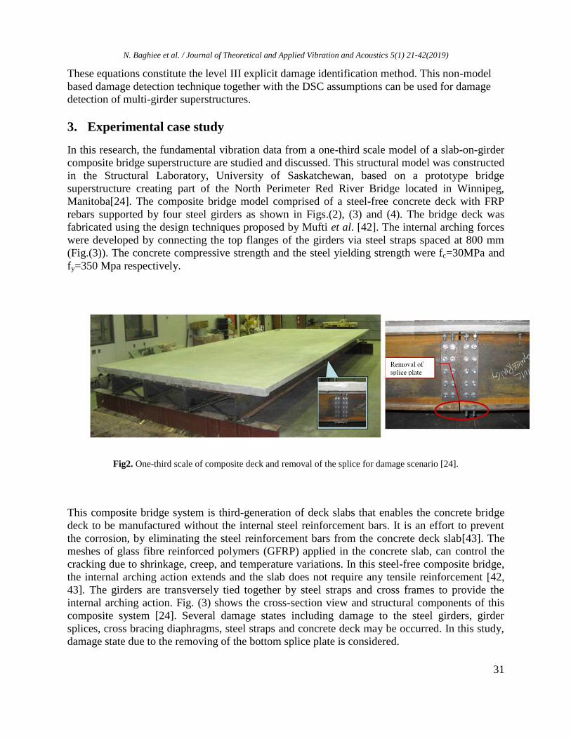
3. Experimental case study
In this research, the fundamental vibration data from a one-third scale model of a slab-on-girder
composite bridge superstructure are studied and discussed. This structural model was constructed
in the Structural Laboratory, University of Saskatchewan, based on a prototype bridge
superstructure creating part of the North Perimeter Red River Bridge located in Winnipeg,
Manitoba[24]. The composite bridge model comprised of a steel-free concrete deck with FRP
rebars supported by four steel girders as shown in Figs.(2), (3) and (4). The bridge deck was
fabricated using the design techniques proposed by Mufti et al. [42]. The internal arching forces
were developed by connecting the top flanges of the girders via steel straps spaced at 800 mm
(Fig.(3)). The concrete compressive strength and the steel yielding strength were fc=30MPa and
fy=350 Mpa respectively.
Fig2. One-third scale of composite deck and removal of the splice for damage scenario [24].
This composite bridge system is third-generation of deck slabs that enables the concrete bridge
deck to be manufactured without the internal steel reinforcement bars. It is an effort to prevent
the corrosion, by eliminating the steel reinforcement bars from the concrete deck slab[43]. The
meshes of glass fibre reinforced polymers (GFRP) applied in the concrete slab, can control the
cracking due to shrinkage, creep, and temperature variations. In this steel-free composite bridge,
the internal arching action extends and the slab does not require any tensile reinforcement [42,
43]. The girders are transversely tied together by steel straps and cross frames to provide the
internal arching action. Fig. (3) shows the cross-section view and structural components of this
composite system [24]. Several damage states including damage to the steel girders, girder
splices, cross bracing diaphragms, steel straps and concrete deck may be occurred. In this study,
damage state due to the removing of the bottom splice plate is considered.

N. Baghiee et al. / Journal of Theoretical and Applied Vibration and Acoustics 5(1) 21-42(2019)
32
Damage Location
SP-X4.0Y2,7
Fig 3. Cross-section of the bridge model deck (dimensions in mm) [24].
The forced vibration tests performed by Wang [24] were conducted in a suitable and controlled
laboratory environmental condition. Wang [24] used 28 accelerometer locations to achieve the
vibration characteristics of the composite deck (seven accelerometers with the same spacing
along each of four girder lines). The harmonic loads for exciting the bridge laboratory model
were provided by a hydraulic shaker with different frequencies to reach the calibration
measurements efficiently [24].
To introduce the sequential damage scenarios in well-controlled and more facilitate condition,
several bolted joints were applied. According to Figs. (2) and (4) a splice plate was applied at the
mid-span of Girder 4. The damage location at x=4.0 m and y=2.7 m, denoted as SP-X4.0Y2.7 in
Fig. (4). In this damaging scenario, the bottom splice plate was removed at mid-span of Girder
and the flexural rigidity reduced at the location [24].
The experimental data were processed by Wang [24] and the vibration characteristics of the
composite deck were obtained using commercial software package SPICE (or MACEC) [44]. In
SPICE software, both the Pick Picking method (PP) and the Stochastic Subspace Identification
method (SSI) were implemented to obtain the modal properties [44, 45]. The vibration data
analysis showed that SSI modal identifications yields more reliable results than the PP method
[24].
Fig 4. Plan of the composite deck, locations of acceleration measurement points and the location of damage to the
steel Girder 4 (dimensions in mm) [24].

N. Baghiee et al. / Journal of Theoretical and Applied Vibration and Acoustics 5(1) 21-42(2019)
33
The natural frequencies of the system from the harmonic excitation test are presented in Table 1.
The natural frequencies decreased as damage was introduced to the structural elements. Damage
is associated with a decrease in the eigenfrequencies, an increase in damping values and
alteration of the modes of vibration. Changes in eigenfrequencies have shown little promise in
detecting the presence of damage.
Table 1. Fundamental frequency of composite bridge superstructure [24]
Fundamental frequency before damage 12.70 Hz
Fundamental frequency after removal the girder splice 12.63 Hz
The experimental dynamic tests and damage scenario of the composite bridge superstructure
were simulated by commercial finite element analysis software ANSYS [24]. This simulation,
provided the composite action for concrete deck and steel girders. The lateral displacements of
the girders were restrained by 2-node linear truss elements as shown in Fig. (3).Wang [24]
calibrated the finite element model to the eigenfrequencies and eigenmodes of the undamaged
laboratory vibration data. After calibrating the finite element model, the damage state to steel
girder splice was introduced into the simulated model. The relative change in the vertical flexural
stiffness was obtained by utilizing an individual vertical load at the damage location and
calculating the correlated displacement. The results of finite element analysis showed a reduction
of 7.76% in the vertical flexural stiffness due to the damage condition shown in Figs. (2) and (4)
[24].
4. Analytical study
In this section, the fundamental vibration characteristics of the experimental case study are
analyzed. For the large bridge structure under consideration, the sensitivity of higher modes to
the damage is less than the first vibration mode [46]. The simply supports of the bridge model
consist of the hinge and roller that were applied for two ends of the girders [24]. Several features
of the non-model based damage detection process of this composite structure including effects of
normalization methods, modal strains calculation, spurious diagnosis, damage localization, and
severity estimation are studied and discussed.
4.1. Modal displacements and curvatures
Experimental mode shapes are modal displacements in the modal space. With the aim of damage
identification based on the modal displacements, the mode shapes should be normalized
consistently to accentuate the local changes due to the damage. It has been observed that the
efficiency of the identification process, strongly depends on the special mode shape
normalization methods[47]. In the present study, two normalization methods namely unit-norm
and unit-area normalization are utilized. By using Eqs. (2) and (3), the unit-area normalized
fundamental mode shapes along each girder line are obtained. Fig. (5), shows that the mode
shape amplitudes obtained by the two normalization methods are significantly different. The
resulting changes in mode shape patterns due to damage are shown in Fig. (6).

N. Baghiee et al. / Journal of Theoretical and Applied Vibration and Acoustics 5(1) 21-42(2019)
34
Girder 1 Girder 2 Girder 3 Girder 4
unit-area normalization unit-norm normalization
Fig5.Comparision of two normalization methods for the fundamental vibration mode of the bridge Girders.
Fig 6. Changes in fundamental modal displacement due to the damage

N. Baghiee et al. / Journal of Theoretical and Applied Vibration and Acoustics 5(1) 21-42(2019)
35
Before Damage After removing the splice plate of the girder4
According to Fig. (6), the unit-area normalization along each girder line can magnify the local
changes that became narrow near the feasible damaged regions. On the other hand, plots for unit-
norm normalization shows a smooth and nearly symmetric mode shape change along all girder
lines. In these smooth plots, the largest positive peak corresponds well to the real location of
damage at mid-span of Girder 4. In the unit-area normalization graphs, the convexity at the
damaged region in Girder Line 4 is obvious and the damage is localized more precisely. Another
large convexity also observed in Girder Line 1, which indicates the possible false damage
diagnosis [24]. Furthermore, the changes of modal displacements along Girder lines 2 and 3 are
slight, indicating the healthy state of these girders.
Fig 7. Mindlin modal strain (curvature) of the fundamental vibration modes of the composite bridge girders with
different normalization methods
Mode shapes or modal displacement changes are not sensitive enough to the damage location,
while the modal strains or modal curvatures changes are more susceptible to the damage
location. The calculation of modal strains may be influenced by large mathematical errors.
Numerical simulations and experiments proved that the Mindlin technique performs well for
modal strain calculation and stiffness determination of beam-like structures[2, 48]. The
efficiency of the Mindlin approach for damage detection of concrete beams was investigated by

N. Baghiee et al. / Journal of Theoretical and Applied Vibration and Acoustics 5(1) 21-42(2019)
36
the authors in the dynamic structural laboratory at Ferdowsi University of Mashhad [48]. A
comparison of the results between these studies shows that the effects of normalization methods
are more pronounced for multiple girder structures than a simple beam specimen. In this Section,
Mindlin approach presented in Section 2.2 is used to calculate the modal strains of the girders.
As shown in Fig. (4), the arrangement of measurement points in the experiment is very coarse
and thus the modal strains cannot be obtained with reasonable accuracy. To overcome this
problem, by using cubic Spline interpolation functions, the measurement points are increased
from 9 to 41 points and the modal strains of each girder are obtained by Mindlin approach. In
this study optimum values of two penalty terms and (Eq. (4)), are found for the fundamental
mode shapes of the girders to minimize the median of relative errors. The optimum values
calculated for and are 100 and 300 respectively.
Mindlin modal strains were obtained for the previously mentioned normalization methods. The
performances of the unit-norm and unit-area normalization methods are shown in Fig. (7). In the
damage scenario, the splice plate in the mid-span of the Girder4 was removed and other girders
were in the healthy state. A reduction of stiffness associated with damage will lead to an increase
in curvature. From Fig. (7), appears that by using the unit-area normalization method a more
consistent mode shape is obtained and the modal strain changes are more pronounced than the
widely used unit-norm method. All the absolute values corresponding to the unit-area
normalization are greater than those of the unit-norm normalization. Although the shape of the
unit-norm normalization strain plots are similar to those obtained by unit-area normalization, the
resulting modal strain values are very small. Since the largest peak in the damage state in the
unit-area normalization graphs, corresponds well to the real location of damage at the middle
span of Girder 4, one concludes that the damage can successfully be located. A large convexity is
also observed in the middle of Girder4, which makes damage localization relatively explicit. The
peak of convexity in Girder4 coincides well with the damage location. However, some large
modal strain variations based on the unit-area normalization also exist along Girder Line 1.
These variations that have no significant trends to a special location, introduce the possibility of
a false diagnosis of damage in Girder 1. This spurious diagnosis which also observed in
numerical studies is common for multi-girder systems [24, 49]. As observed in Fig. (7), the
amplitudes of modal strains change slightly along Girder lines 2 and 3 after damage. These slight
changes may depend on the sensor placement and experimental uncertainties and not due to
damage in Girder lines 2 and 3.
These observations reveal the better performance of the unit-area normalization method in
damage detection procedures. In the following, the modal strains obtained from unit-area
normalized mode shapes are employed to locate damage and distinguish between correct and
false diagnoses.
4.2. Spurious damage identification
A common nature of spurious (non-physical) damage identification that arise in multi-girder
composite systems is the fluctuations of modal displacements and modal strain diagrams [24,
49]. It is shown that these fluctuations may result in false alarms during the damage detection
process. The authors observed that damage detection results of several classic and new
methodologies utilizing the modal data of the multi-girder bridge led to the false alarms in Girder

N. Baghiee et al. / Journal of Theoretical and Applied Vibration and Acoustics 5(1) 21-42(2019)
37
1. Therefore these spurious modal displacements should be discriminated between the modal
data.
In the present study, by inspiration of spurious displacement and strains concepts in structural
analysis, these non-physical phenomena are identified. Eq. (13) was introduced in Section 2.3 to
clarify the false alarms from the exact ones (level I damage identification). It is a strain-based
formula obtained by the aim of a generalized mean value theorem and gives the relative modal
strain energy changes (ΔUi). In multi-girder systems, spurious changes in curvatures are
observed but don’t lead to an increase in ΔUi. In these cases, the structure becomes stiffer and
the change of relative modal strain energy decreases.
For the case study of this article, the ΔUi values of bridge girders have been calculated by Eq.
(13) and Mindlin modal strains obtained from the unit area normalized fundamental mode shape.
Table 2 shows that the relative modal strain energy change in Girder 1 is negative. Thus, it is a
false diagnosis. The ΔUi values for Girder 2 and 3 are very small that explains undamaged states.
In Girder 4 the ΔUi value is positive and damage has been occurred.
Table 2. The relative modal strain energy changes (ΔUi ) values of girders
of composite bridge superstructure
Girders Girder 1 Girder 2 Girder3 Girder4
ΔUi -0.21932 -0.067241 0.083321 0.31708
Strain energy changes 22% decrease Small changes Small changes 32% increase
Damage diagnosis Spurious No damage No damage Damage occurrence
4.3. Damage localization and severity estimation
In the previous section the damage occurrence in Girder 4 was distinguished from false alarms.
However, the location of damage in Girder 4 has not yet been determined. For damage
localization of Girder 4, the beam is divided into 40 elements and the strain energy changes of
each element are calculated by Eq. (14). The candidate damage elements can be identified by j
index in Eq. (20). According to statistical approaches, the damaged elements are assumed as
random variables j for jth element. The damage location is identified by the hypothesis test.
Before employing the hypothesis test, the damage indices are standardized using Eq. (21). The
decision-making criterion for assigning the location of the damage is based on the Hypothesis
testing and damage threshold value. In this study, the threshold value of z is selected to achieve
the appropriate confidence level. This criterion corresponds to a one-tailed test at a significance
level of 0.023 (97.7% confidence level)[50] .The z score (z) associated with this significance
level equals 2. If zj < z null Hypothesis (H0) is chosen. When zj > z, the element is damaged and
the alternate Hypothesis is chosen.

N. Baghiee et al. / Journal of Theoretical and Applied Vibration and Acoustics 5(1) 21-42(2019)
38
Damage location
Threshold
level z=2
Fig 8. Damage location of Girder 4 by the normalized strain energy index
The results of modal strain energy analysis are shown in Fig. (8) for Girder4. As observed in Fig.
(8), the damage location is well determined by normalized damage index. In the mid-span of
Girder 4, the normalized damage index values are greater than threshold level (z=2). It well
coincides with the actual location of the removed splice plate in Girder4. Using the Hypothesis
test, a damage index for each degree of freedom of the Girders is obtained. Due to the
uncertainties inherent in the practical dynamic tests such as fabrication process and some over
design members, the fundamental vibration mode is not entirely symmetric [24]. These
asymmetries in the mode shapes affect significantly on the modal strains. As a result, the
diagram of modal strain energy index became unsymmetrical.
Fig 9. Damage localization and severity estimation of Girder 4 by applying ISR method and DCS
Damage location
Damage severity 10%
N. Baghiee et al. / Journal of Theoretical and Applied Vibration and Acoustics 5(1) 21-42(2019)
39
ΔUi>0
Fundamental
vibration modes
of girder lines
Unit-area
normalization
Calculating the Mindlin
modal strains by DSC
assumptions
Relative modal strain
energy changes before
and after damage (ΔUi)
No damage
Arranging the ISR
equations by DSC
assumptions
Damage
localization and
severity estimation
No Yes No
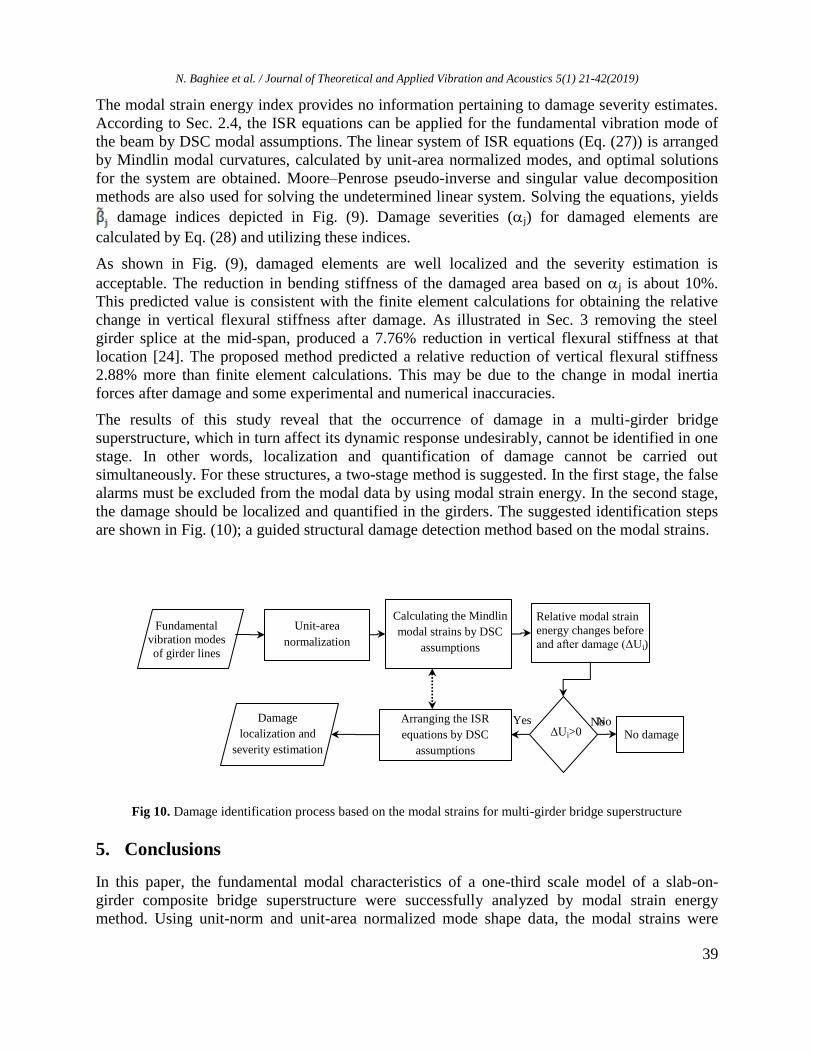
The modal strain energy index provides no information pertaining to damage severity estimates.
According to Sec. 2.4, the ISR equations can be applied for the fundamental vibration mode of
the beam by DSC modal assumptions. The linear system of ISR equations (Eq. (27)) is arranged
by Mindlin modal curvatures, calculated by unit-area normalized modes, and optimal solutions
for the system are obtained. Moore–Penrose pseudo-inverse and singular value decomposition
methods are also used for solving the undetermined linear system. Solving the equations, yields
damage indices depicted in Fig. (9). Damage severities (j) for damaged elements are
calculated by Eq. (28) and utilizing these indices.
As shown in Fig. (9), damaged elements are well localized and the severity estimation is
acceptable. The reduction in bending stiffness of the damaged area based on j is about 10%.
This predicted value is consistent with the finite element calculations for obtaining the relative
change in vertical flexural stiffness after damage. As illustrated in Sec. 3 removing the steel
girder splice at the mid-span, produced a 7.76% reduction in vertical flexural stiffness at that
location [24]. The proposed method predicted a relative reduction of vertical flexural stiffness
2.88% more than finite element calculations. This may be due to the change in modal inertia
forces after damage and some experimental and numerical inaccuracies.
The results of this study reveal that the occurrence of damage in a multi-girder bridge
superstructure, which in turn affect its dynamic response undesirably, cannot be identified in one
stage. In other words, localization and quantification of damage cannot be carried out
simultaneously. For these structures, a two-stage method is suggested. In the first stage, the false
alarms must be excluded from the modal data by using modal strain energy. In the second stage,
the damage should be localized and quantified in the girders. The suggested identification steps
are shown in Fig. (10); a guided structural damage detection method based on the modal strains.
Fig 10. Damage identification process based on the modal strains for multi-girder bridge superstructure
5. Conclusions
In this paper, the fundamental modal characteristics of a one-third scale model of a slab-on-
girder composite bridge superstructure were successfully analyzed by modal strain energy
method. Using unit-norm and unit-area normalized mode shape data, the modal strains were
N. Baghiee et al. / Journal of Theoretical and Applied Vibration and Acoustics 5(1) 21-42(2019)
40
calculated by Mindlin's approach. In this process, the effects of two normalization methods on
damage detection of the scaled bridge were studied and discussed. Finally, a new damage
identification approach was proposed. The following conclusions are drawn:
Assessments of damage patterns show the drawbacks of a widely used unit-norm
normalization method in the damage identification process. The drawbacks consist of
smooth and wide spread changes of the mode shapes with no clear trends to the damage
location and very small values of modal strains.
The Mindlin approach is sensitive to the normalization methods. The Mindlin modal
strains obtained from the unit-area normalization method produce more pronounced
damage patterns. The values of these modal strains are approximately eight times greater
than those obtained by the unit-norm method. The accuracy of Mindlin damage pattern
based on the unit-area normalization is about 85 percent for a multi-girder bridge
structure.
The spurious diagnosis that is common in multiple girder systems was studied by modal
strain approach. The false detection is distinguished from the exact ones by the use of
relative total modal strain energy changes in the post and pre-damaged states. The
negative values of relative total modal strain energy changes demonstrated the spurious
diagnosis.
The structural damage is localized and quantified by using the ISR equations
accompanying direct stiffness assumptions. The results of the level III damage detection
process indicate that the process provides an excellent assessment of damage location and
severity of the damage. The bending stiffness of the damaged area is estimated to be
reduced by 10%, which is 2.88% more than a finite element analysis. This may be due to
the change in modal inertia forces after damage and some experimental and numerical
uncertainties.
References
[1] A. Rytter, Vibrational based inspection of civil engineering structures, in, Dept. of Building Technology and
Structural Engineering, Aalborg University, 1993.
[2] J. Maeck, Damage assessment of civil engineering structures by vibration monitoring, in: Department of Civil
Engineering, K.U.Leuven, Belgium (2003).
[3] M. Cao, L. Ye, L. Zhou, Z. Su, R. Bai, Sensitivity of fundamental mode shape and static deflection for damage
identification in cantilever beams, Mechanical Systems and Signal Processing, 25 (2011) 630-643.
[4] Y.Y. Li, Hypersensitivity of strain-based indicators for structural damage identification: A review, Mechanical
Systems and Signal Processing, 24 (2010) 653-664.
[5] J. Moughty, J. Casas, A state of the art review of modal-based damage detection in bridges: development,
challenges, and solutions, Applied Sciences, 7 (2017) 510-534
[6] D. Anastasopoulos, M. De Smedt, L. Vandewalle, G. De Roeck, E.P.B. Reynders, Damage identification using
modal strains identified from operational fiber-optic Bragg grating data, Structural Health Monitoring, 17 (2018)
1441-1459.
[7] J. Ciambella, A. Pau, F. Vestroni, Modal curvature-based damage localization in weakly damaged continuous
beams, Mechanical Systems and Signal Processing, 121 (2019) 171-182.
[8] A.K. Pandey, M. Biswas, M.M. Samman, Damage detection from changes in curvature mode shapes, Journal of
sound and vibration, 145 (1991) 321-332.
[9] O.S. Salawu, C. Williams, Bridge assessment using forced-vibration testing, Journal of structural engineering,
121 (1995) 161-173.
N. Baghiee et al. / Journal of Theoretical and Applied Vibration and Acoustics 5(1) 21-42(2019)
41
[10] M.M. Wahab, G. De .Roeck, Damage detection in bridges using modal curvatures: application to a real damage
scenario, Journal of Sound and vibration, 226 (1999) 217-235.
[11] J. Maeck, G. De Roeck, Dynamic bending and torsion stiffness derivation from modal curvatures and torsion
rates, Journal of Sound and Vibration, 225 (1999) 153-170.
[12] S. Dincal, N. Stubbs, Nondestructive damage detection in Euler–Bernoulli beams using nodal curvatures—Part
I: Theory and numerical verification, Structural Control and Health Monitoring, 21 (2014) 303-316.
[13] S. Dincal, N. Stubbs, Nondestructive damage detection in Euler–Bernoulli beams using nodal curvatures—Part
II: Field measurements, Structural Control and Health Monitoring, 21 (2014) 331-341.
[14] S. Dincal, N. Stubbs, Damage evaluation of Timoshenko beams using invariant stress resultants, Engineering
Structures, 56 (2013) 2052-2064.
[15] J. Zhang, Non-Destructive Evaluation Method Based On Dynamic Invariant Stress Resultants, in: M.Sc. thesis,
Texas A&M University, 2015.
[16] J. Zhang, R. Barroso, S. Hurlebaus, N. Stubbs, Non-Destructive Evaluation Method Based On Dynamic
Invariant Stress Resultants, in, 6th International Conference on Experimental Vibration Analysis for Civil
Engineering Structures, EDP Sciences, 2015.
[17] Y. Wang, H. Hao, Damage identification of slab–girder structures: experimental studies, Journal of civil
structural health monitoring, 3 (2013) 93-103.
[18] A. Morassi, L. Rocchetto, A damage analysis of steel-concrete composite beams via dynamic methods: Part I.
Experimental results, Modal Analysis, 9 (2003) 507-527.
[19] M. Dilena, A. Morassi, A damage analysis of steel-concrete composite beams via dynamic methods: Part II.
Analytical models and damage detection, Modal Analysis, 9 (2003) 529-565.
[20] M. Dilena, A. Morassi, Vibrations of steel–concrete composite beams with partially degraded connection and
applications to damage detection, Journal of Sound and Vibration, 320 (2009) 101-124.
[21] K. Liu, G. De Roeck, Damage detection of shear connectors in composite bridges, Structural Health
Monitoring, 8 (2009) 345-356.
[22] H.W. Shih, D.P. Thambiratnam, T.H.T. Chan, Damage detection in slab‐on‐girder bridges using vibration
characteristics, Structural Control and Health Monitoring, 20 (2013) 1271-1290.
[23] Y. Xia, H. Hao, A.J. Deeks, Dynamic assessment of shear connectors in slab–girder bridges, Engineering
Structures, 29 (2007) 1475-1486.
[24] Y. Wang, Vibration-Based Damage Detection on a Multi-Girder Bridge Superstructure, in, University of
Saskatchewan, 2011.
[25] O. Huth, G. Feltrin, J. Maeck, N. Kilic, M. Motavalli, Damage identification using modal data: Experiences on
a prestressed concrete bridge, Journal of Structural Engineering, 131 (2005) 1898-1910.
[26] C.P. Ratcliffe, Damage detection using a modified Laplacian operator on mode shape data, Journal of Sound
and Vibration, 204 (1997) 505-517.
[27] Y.K. Ho, D.J. Ewins, On the structural damage identification with mode shapes, in: International conference
on system identification and structural health monitoring, 2000, pp. 677-686.
[28] Y. Yang, H. Liu, K.M. Mosalam, S. Huang, An improved direct stiffness calculation method for damage
detection of beam structures, Structural Control and Health Monitoring, 20 (2013) 835-851.
[29] Y. Yang, K.M. Mosalam, G. Liu, X. Wang, Damage Detection Using Improved Direct Stiffness Calculations—
A Case Study, International Journal of Structural Stability and Dynamics, 16 (2016) 1640002.
[30] N. Stubbs, J.T. Kim, K. Topole, An efficient and robust algorithm for damage localization in offshore
platforms, in: Proceedings of the ASCE 10th structures congress, 1992, pp. 543-546.
[31] N. Stubbs, J.T. Kim, C.R. Farrar, Field verification of a nondestructive damage localization and severity
estimation algorithm, in: Proceedings-SPIE the international society for optical engineering, SPIE International
Society for Optical, 1995, pp. 210-218.
[32] K. Topole, N. Stubbs, Non‐destructive damage evaluation of a structure from limited modal parameters,
Earthquake engineering & structural dynamics, 24 (1995) 1427-1436.
[33] Z.Y. Shi, S.S. Law, L.M. Zhang, Structural damage detection from modal strain energy change, Journal of
engineering mechanics, 126 (2000) 1216-1223.
[34] Z.Y. Shi, S.S. Law, L.M. Zhang, Improved damage quantification from elemental modal strain energy change,
Journal of engineering mechanics, 128 (2002) 521-529.
[35] A. Alvandi, C. Cremona, Assessment of vibration-based damage identification techniques, Journal of sound and
vibration, 292 (2006) 179-202.

N. Baghiee et al. / Journal of Theoretical and Applied Vibration and Acoustics 5(1) 21-42(2019)
42
[36] P. Cornwell, S.W. Doebling, C.R. Farrar, Application of the strain energy damage detection method to plate-
like structures, Journal of sound and vibration, 224 (1999) 359-374.
[37] S. Choi, S. Park, N. Stubbs, Nondestructive damage detection in structures using changes in compliance,
International Journal of Solids and Structures, 42 (2005) 4494-4513.
[38] J.D. Gibson, J.L. Melsa, Introduction to nonparametric detection with applications, Academic Press, 1976.
[39] A.J. Reiff, M. Sanayei, R.M. Vogel, Statistical bridge damage detection using girder distribution factors,
Engineering Structures, 109 (2016) 139-151.
[40] R.L. Ott, An introduction to statistical methods and data analysis, Wadsworth Inc, USA, 1993.
[41] E. Kreyszig, Advanced Engineering Mathematics, 8-th edition, in, John Wiley & Sons, 1999.
[42] A.A. Mufti, L.G. Jaeger, B. Bakht, L.D. Wegner, Experimental investigation of fibre-reinforced concrete deck
slabs without internal steel reinforcement, Canadian Journal of Civil Engineering, 20 (1993) 398-406.
[43] A.H. Salem, M.A. El-Aghoury, E.Y. Sayed-Ahmed, T.S. Moustafa, Composite steel-free deck bridges:
Numerical modelling and pilot parametric study, Canadian Journal of Civil Engineering, 29 (2002) 662-678.
[44] B. Van den Branden, B. Peeters, G. De Roeck, Introduction to MACEC v2. 0: Modal analysis on civil
engineering constructions, User Guide and Case Studies, Katholieke Universiteit Leuven, (1999).
[45] P. Van Overschee, B. De Moor, Subspace identification for linear systems: Theory—Implementation—
Applications, Kluwer Academic Publishers. Dordrecht, the Netherlands 1996.
[46] Z. Zhou, Vibration-based damage detection of simple bridge superstructures, in Department of Civil and
Geological Engineering, University of Saskatchewan, Saskatoon, 2006.
[47] S. Beskhyroun, L.D. Wegner, B.F. Sparling, New methodology for the application of vibration‐based damage
detection techniques, Structural Control and Health Monitoring, 19 (2012) 632-649.
[48] N. Baghiee, M.R. Esfahani, K. Moslem, Studies on damage and FRP strengthening of reinforced concrete
beams by vibration monitoring, Engineering Structures, 31 (2009) 875-893.
[49] A.B. Siddique, Structural health monitoring of Attridge Drive overpass, in, University of Saskatchewan, 2008.
[50] J.T. Kim, N. Stubbs, Model-uncertainty impact and damage-detection accuracy in plate girder, Journal of
Structural Engineering, 121 (1995) 1409-1417.